Embed Size (px)
Citation preview
1
PL100Pump for LPG DispensersOperation and Maintenance Manual
M-287Rev. E

2
Table of Contents
Principle of Operation 3PL100 Features 3Motor Features 3Installing the PL100 4Inlet Piping Requirements: 4Outlet Piping Requirements: 4Bypass System Requirements: 4Motor Installation 5Operation of Your PL100 Pump 6Filling New Cylinders and Tanks 6Preventative Maintenance 6Repair Service 6Extended Storage Procedures 6Seal Replacement Instructions 7Parts Detail 10Specifications 11Performance 11Dimensions 11Troubleshooting Guide 12
3
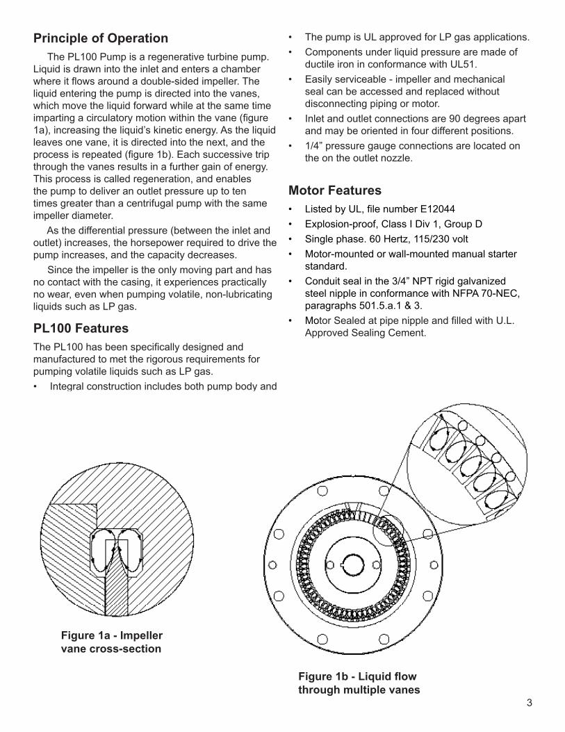
Principle of Operation The PL100 Pump is a regenerative turbine pump. Liquid is drawn into the inlet and enters a chamber where it flows around a double-sided impeller. The liquid entering the pump is directed into the vanes, which move the liquid forward while at the same time imparting a circulatory motion within the vane (figure 1a), increasing the liquid’s kinetic energy. As the liquid leaves one vane, it is directed into the next, and the process is repeated (figure 1b). Each successive trip through the vanes results in a further gain of energy. This process is called regeneration, and enables the pump to deliver an outlet pressure up to ten times greater than a centrifugal pump with the same impeller diameter. As the differential pressure (between the inlet and outlet) increases, the horsepower required to drive the pump increases, and the capacity decreases. Since the impeller is the only moving part and has no contact with the casing, it experiences practically no wear, even when pumping volatile, non-lubricating liquids such as LP gas.
PL100 Features The PL100 has been specifically designed and manufactured to met the rigorous requirements for pumping volatile liquids such as LP gas.• Integral construction includes both pump body and
motor.
• The pump is UL approved for LP gas applications.• Components under liquid pressure are made of
ductile iron in conformance with UL51.• Easily serviceable - impeller and mechanical
seal can be accessed and replaced without disconnecting piping or motor.
• Inlet and outlet connections are 90 degrees apart and may be oriented in four different positions.
• 1/4” pressure gauge connections are located on the on the outlet nozzle.
Motor Features• Listed by UL, file number E12044• Explosion-proof, Class I Div 1, Group D• Single phase. 60 Hertz, 115/230 volt• Motor-mounted or wall-mounted manual starter
standard. • Conduit seal in the 3/4” NPT rigid galvanized
steel nipple in conformance with NFPA 70-NEC, paragraphs 501.5.a.1 & 3.
• Motor Sealed at pipe nipple and filled with U.L. Approved Sealing Cement.
Figure 1a - Impeller vane cross-section
Figure1b-Liquidflowthrough multiple vanes

4
Installing the PL100 Proper installation is critical when pumping volatile liquids. The following installation procedures have been thoroughly tested and should be followed as closely as possible to ensure peak performance and reliability. Specific installations may require slight variations in the piping design, but the fundamental principles must be observed. If it is necessary to reorient the pump nozzles, the pump cover, impeller, and mechanical seal must be removed, followed by the four nuts securing the housing to the motor. The housing can then be pulled off the studs and reoriented. Reassemble in the reverse order. It is critical that the pump not be allowed to run dry. Damage to the seal could be caused by product vaporization due to the inlet being restricted by an inadequate pipe size, restricted strainer, or improper location relative to the tank. Locate the pump as close to the storage tank as possible. The total length of the inlet tubing, from the pump to the tank, must not exceed 12 feet. Always locate the pump as low as possible below the level of the tank so that the product is gravity-fed to the pump location. (Liquefied gases can vaporize when drawn into a pump by suction.) The pump inlet should be at least 2 feet below the bottom of the tank, but 4 feet would be optimum.
Inlet Piping Requirements:1. The tank excess flow valve should have a flow
rate of 1.5 to 2 times the flow rate of the pump at operating conditions.
2. The tank shutoff valve should be an angle valve or a free flow type — not a standard globe valve.
3. A Y-type strainer with 1/16” mesh screen, must be used on the inlet line.
4. A section of flexible hose should be used at the inlet and outlet to eliminate strain from the fixed piping.
5. Unions must be installed near the pump inlet and outlet nozzles.
6. Inlet piping must be adequate to ensure a constant supply of liquid. Never use an inlet line of smaller diameter than the pump inlet. The same size line may be used for shorter runs, but for longer runs the line should be larger than the pump inlet.
7. Always use an eccentric reducer (not a concentric reducer) to reduce the inlet line size in the horizontal section of the inlet piping. The reducer should be installed flat side up to prevent vapor build-up.
8. The inlet line must be level or slope downward to the pump.
Outlet Piping Requirements:1. A pressure gauge is critical for monitoring the
pump’s performance. Install the gauge in the opening on the outlet nozzle or in the outlet piping close to the pump.
2. A hydrostatic relief valve must be installed between any two valves that can be closed.
3. If the length of the outlet piping exceeds 50 feet, install a check valve near the pump outlet.
4. The outlet piping size is 1 inch length, and restrictions produce different pressure drop that effects flow rate.
Bypass System Requirements:1. The pump bypass system is required to vent
vapors and to act as a differential relief valve to insure proper pump operation.
2. The line must rise uninterrupted from the pump to the tank.
3. Always pipe the by-pass valve back to a port in the storage tank’s vapor section, never back into the inlet piping of the pump.
4. Connect the bypass line using an excess flow valve or a vapor return valve (not a filler valve or back check valve) to allow for proper vapor return.
5. Avoid creating low spots in the by-pass line which can trap vapor and affect pump priming.
5
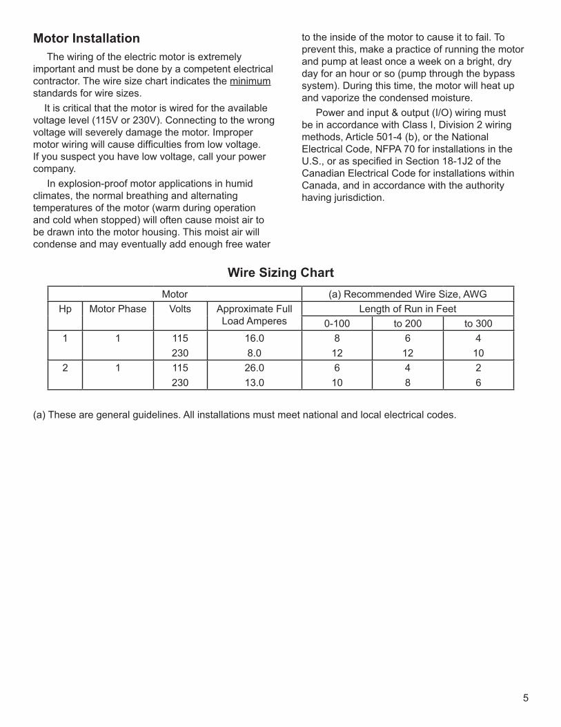
Motor Installation The wiring of the electric motor is extremely important and must be done by a competent electrical contractor. The wire size chart indicates the minimum standards for wire sizes. It is critical that the motor is wired for the available voltage level (115V or 230V). Connecting to the wrong voltage will severely damage the motor. Improper motor wiring will cause difficulties from low voltage. If you suspect you have low voltage, call your power company. In explosion-proof motor applications in humid climates, the normal breathing and alternating temperatures of the motor (warm during operation and cold when stopped) will often cause moist air to be drawn into the motor housing. This moist air will condense and may eventually add enough free water
Wire Sizing ChartMotor (a) Recommended Wire Size, AWG
Hp Motor Phase Volts Approximate Full Load Amperes
Length of Run in Feet0-100 to 200 to 300
1 1 115230
16.08.0
812
612
410
2 1 115230
26.013.0
610
48
26
to the inside of the motor to cause it to fail. To prevent this, make a practice of running the motor and pump at least once a week on a bright, dry day for an hour or so (pump through the bypass system). During this time, the motor will heat up and vaporize the condensed moisture. Power and input & output (I/O) wiring must be in accordance with Class I, Division 2 wiring methods, Article 501-4 (b), or the National Electrical Code, NFPA 70 for installations in the U.S., or as specified in Section 18-1J2 of the Canadian Electrical Code for installations within Canada, and in accordance with the authority having jurisdiction.
(a) These are general guidelines. All installations must meet national and local electrical codes.
6
Impeller Replacement Replacement is a matter of removing the cover and removing the old impeller from the shaft. If the old impeller is tight on the shaft, threaded bolt holes are provided in the impeller to use for pulling. The new impeller must be a good slip fit on the shaft; it should ”float” on the shaft, so it may be necessary to sand the shaft lightly to get the proper fit.
Impeller and Seal ReplacementSeal replacement instructions begin on the next page. They can also be referenced in M-287-1
Extended Storage1. Fill or thoroughly flush the pump with a light
rust-inhibiting oil. (If the pump is flushed with oil, placing some desiccant packets inside the pump will provide added protection.)
2. Piping and tanks not in service should also be protected, as the rust that forms can destroy the pump’s seals almost immediately after startup.
3. Plug all pump openings. 4. Store in a dry location. 5. Before placing the pump back into service,
drain the oil and remove any desiccant packets.
OperationThe following steps should be performed for the initial pumping operation:1. Close shutoff valve on the end of the delivery
hose.2. Open the storage tank bottom shutoff valve.3. Open the storage tank shutoff valve of the
bypass system.4. Check the motor for the proper voltage. (See
instructions under driver installation.)5. Start the pump and circulate liquid through the
bypass system.6. Adjust the bypass valve by turning the adjusting
screw out until the pump pressure gauge shows nearly the same pressure it did before you started the pump. Screw the adjusting screw in until the pressure gauge indicates the pump is providing sufficient pressure to meet system differentia pressure requirements (typically 50 to 60 psi above tank vapor pressure).
Filling New Cylinders and Tanks All new containers must be purged of air before filling with LPG to ensure ease of filling and consistency of gas supply from the container.
Preventative MaintenanceLubrication This model is equipped with lifetime lubricated bearings.
Repair Service After a long service life, repairs are limited to replacing the impeller or mechanical seal. The only wearing part influencing the pumping action is the impeller, so we suggest the pump be given an “efficiency” test before any attempt is made to repair it. The trouble may lie in the piping system rather than in the pump. lf the pump will still produce as much differential pressure when circulating through the bypass system as it did when new, you may be sure your problem is elsewhere. If the pump does not produce as much pressure as it did originally, remove the cover and inspect the impeller. If the Impeller is badly damaged, it must be replaced.
7
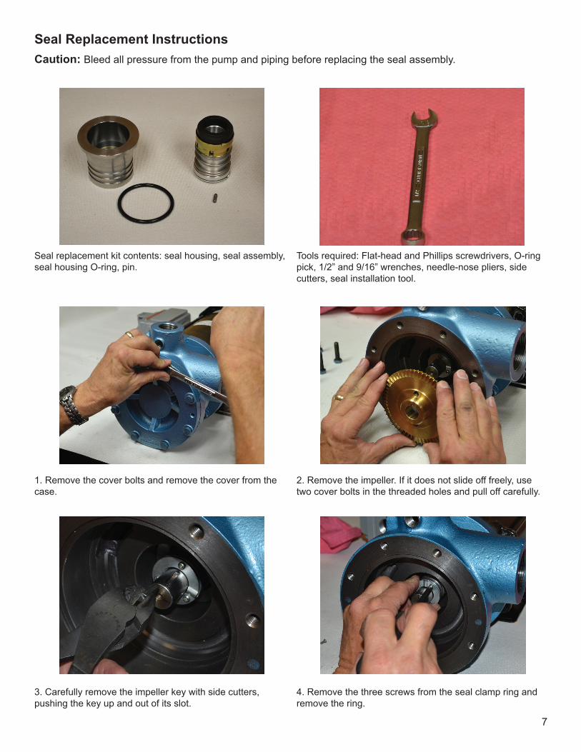
Seal Replacement InstructionsCaution: Bleed all pressure from the pump and piping before replacing the seal assembly.
1. Remove the cover bolts and remove the cover from the case.
4. Remove the three screws from the seal clamp ring and remove the ring.
3. Carefully remove the impeller key with side cutters, pushing the key up and out of its slot.
2. Remove the impeller. If it does not slide off freely, use two cover bolts in the threaded holes and pull off carefully.
Tools required: Flat-head and Phillips screwdrivers, O-ring pick, 1/2” and 9/16” wrenches, needle-nose pliers, side cutters, seal installation tool.
Seal replacement kit contents: seal housing, seal assembly, seal housing O-ring, pin.
8
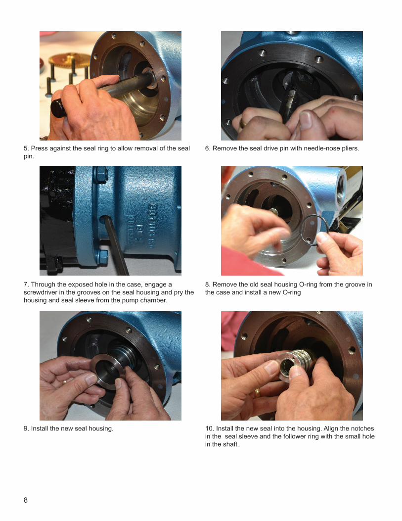
5. Press against the seal ring to allow removal of the seal pin.
6. Remove the seal drive pin with needle-nose pliers.
7. Through the exposed hole in the case, engage a screwdriver in the grooves on the seal housing and pry the housing and seal sleeve from the pump chamber.
8. Remove the old seal housing O-ring from the groove in the case and install a new O-ring
9. Install the new seal housing. 10. Install the new seal into the housing. Align the notches in the seal sleeve and the follower ring with the small hole in the shaft.

9
11. Push back the seal sleeve and the follower ring. Using needle-nose pliers, drop a new drive pin into the hole in the shaft.
12. Reinstall the seal clamp ring.
13. Use the side cutter to install a new impeller key into the keyway slot. The impeller must slide over the shaft and key freely.
14. Replace the impeller, making sure that it slides freely over the shaft and key.
15. Replace the pump cover O-ring. 16. Replace the cover and cover bolts.

10
Ref. No.
Part No. Description Qty.1 HP
Qty.2 HP
1 601103-001 1 13 601168-000 Seal assembly 1 14 601104-001 Cover 1 15 601170-001 Housing O-ring 1 16 601167-00X Case clearance
shimAs req.
As req.
7 601177-001 Case O-ring 1 1
ConstructionPart Material, StandardCase, cover Ductile iron ASTM A536Impeller BronzeImpeller key SteelSeal seat Steelseal rotor CarbonSeal metal parts SteelSeal sleeve AluminumSeal follower AluminumSeal housing SteelO-rings Buna-NBearings Ball
Parts Detail
Ref. No.
Part No. Description 1 HPQty.
2HPQty.
9 008325-014 SCR 3/8-16 X I S.H.C.S.
1 1
10 601172-001 Hex head cap screw 8 811 601173-001 Pipe plug, 3/4” NPT 1 112 601174-001 Pipe plug, 1/4” NPT 1 1
13A 601174-001 Motor 1 hp 114 601176-001 Woodruff key 1 115 601105-001 Impeller 1 1
13B 601174-002 Motor 2 HP 1
11
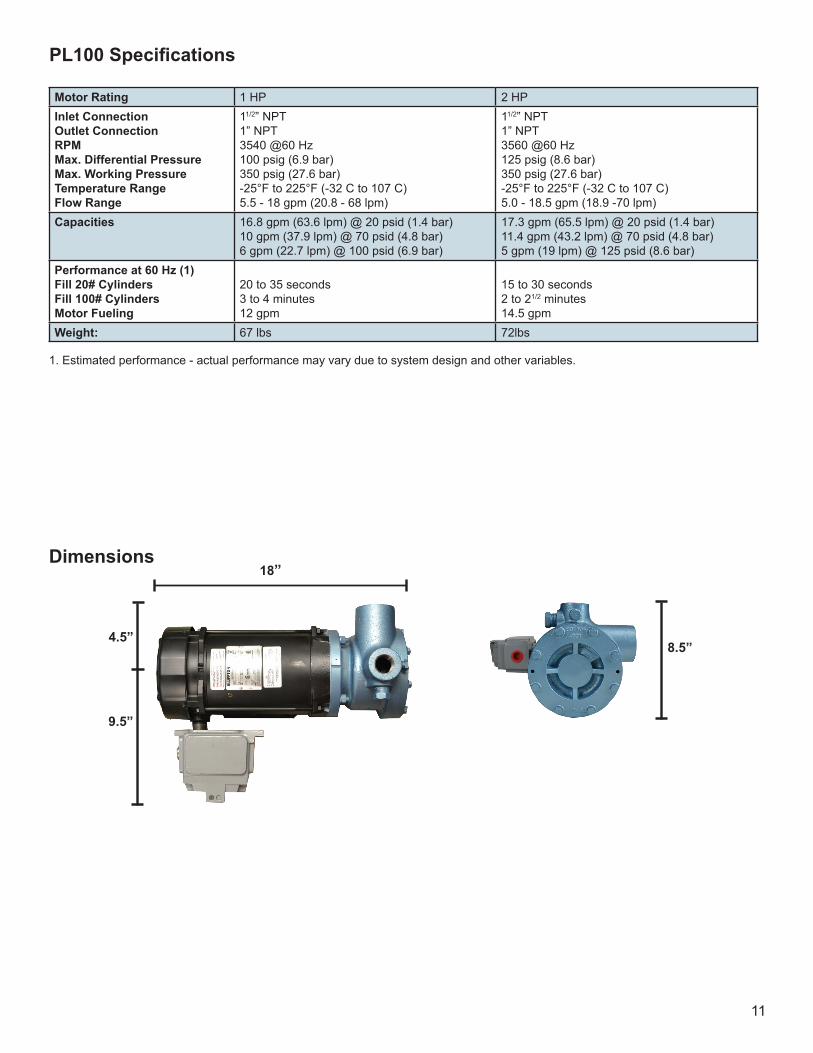
Dimensions18”
9.5”
4.5”8.5”
Motor Rating 1 HP 2 HPInlet ConnectionOutlet ConnectionRPMMax. Differential PressureMax. Working PressureTemperature RangeFlow Range
11/2” NPT1” NPT3540 @60 Hz100 psig (6.9 bar)350 psig (27.6 bar)-25°F to 225°F (-32 C to 107 C)5.5 - 18 gpm (20.8 - 68 lpm)
11/2” NPT1” NPT3560 @60 Hz125 psig (8.6 bar)350 psig (27.6 bar)-25°F to 225°F (-32 C to 107 C)5.0 - 18.5 gpm (18.9 -70 lpm)
Capacities 16.8 gpm (63.6 lpm) @ 20 psid (1.4 bar)10 gpm (37.9 lpm) @ 70 psid (4.8 bar)6 gpm (22.7 lpm) @ 100 psid (6.9 bar)
17.3 gpm (65.5 lpm) @ 20 psid (1.4 bar)11.4 gpm (43.2 lpm) @ 70 psid (4.8 bar)5 gpm (19 lpm) @ 125 psid (8.6 bar)
Performance at 60 Hz (1)Fill 20# CylindersFill 100# CylindersMotor Fueling
20 to 35 seconds3 to 4 minutes12 gpm
15 to 30 seconds2 to 21/2 minutes14.5 gpm
Weight: 67 lbs 72lbs
PL100Specifications
1. Estimated performance - actual performance may vary due to system design and other variables.
12
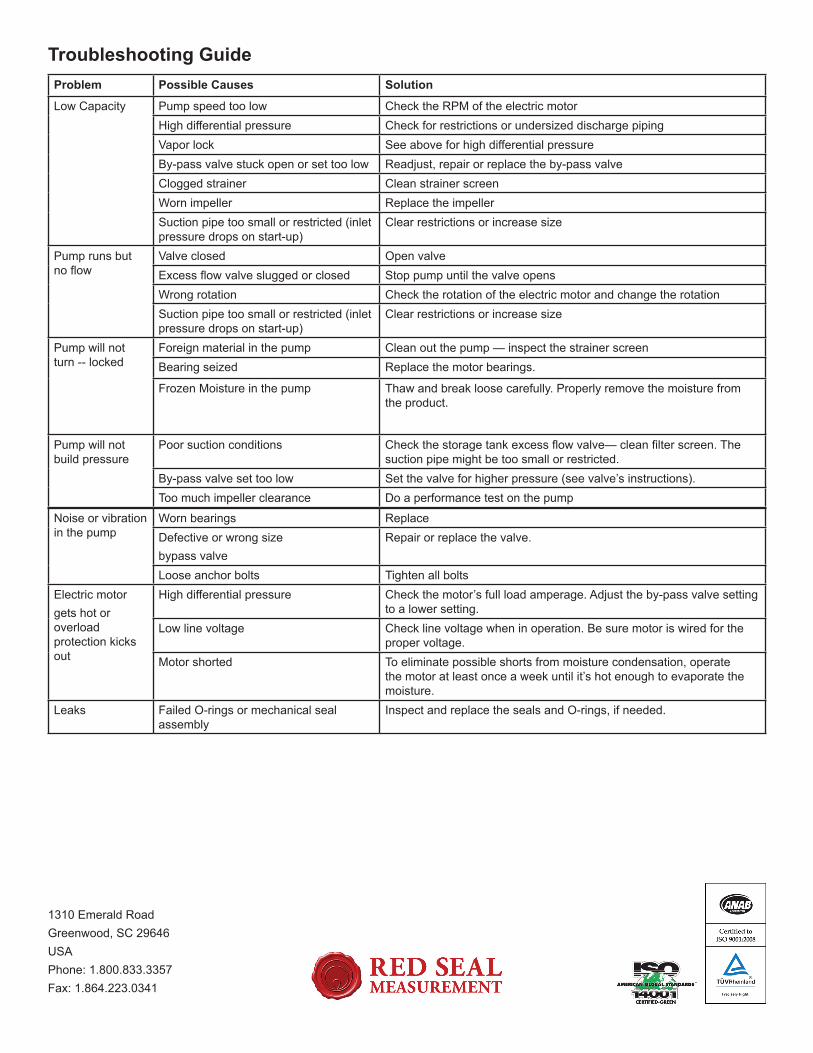
Troubleshooting GuideProblem Possible Causes Solution
Low Capacity Pump speed too low Check the RPM of the electric motorHigh differential pressure Check for restrictions or undersized discharge pipingVapor lock See above for high differential pressureBy-pass valve stuck open or set too low Readjust, repair or replace the by-pass valveClogged strainer Clean strainer screenWorn impeller Replace the impellerSuction pipe too small or restricted (inlet pressure drops on start-up)
Clear restrictions or increase size
Pump runs but no flow
Valve closed Open valveExcess flow valve slugged or closed Stop pump until the valve opensWrong rotation Check the rotation of the electric motor and change the rotationSuction pipe too small or restricted (inlet pressure drops on start-up)
Clear restrictions or increase size
Pump will not turn -- locked
Foreign material in the pump Clean out the pump — inspect the strainer screenBearing seized Replace the motor bearings.
Frozen Moisture in the pump Thaw and break loose carefully. Properly remove the moisture from the product.
Pump will not build pressure
Poor suction conditions Check the storage tank excess flow valve— clean filter screen. The suction pipe might be too small or restricted.
By-pass valve set too low Set the valve for higher pressure (see valve’s instructions).Too much impeller clearance Do a performance test on the pump
Noise or vibration in the pump
Worn bearings ReplaceDefective or wrong sizebypass valve
Repair or replace the valve.
Loose anchor bolts Tighten all boltsElectric motorgets hot or overload protection kicks out
High differential pressure Check the motor’s full load amperage. Adjust the by-pass valve setting to a lower setting.
Low line voltage Check line voltage when in operation. Be sure motor is wired for the proper voltage.
Motor shorted To eliminate possible shorts from moisture condensation, operate the motor at least once a week until it’s hot enough to evaporate the moisture.
Leaks Failed O-rings or mechanical seal assembly
Inspect and replace the seals and O-rings, if needed.
1310 Emerald RoadGreenwood, SC 29646USAPhone: 1.800.833.3357Fax: 1.864.223.0341