Embed Size (px)
Citation preview
M-100 ApplianceHardware Reference Guide
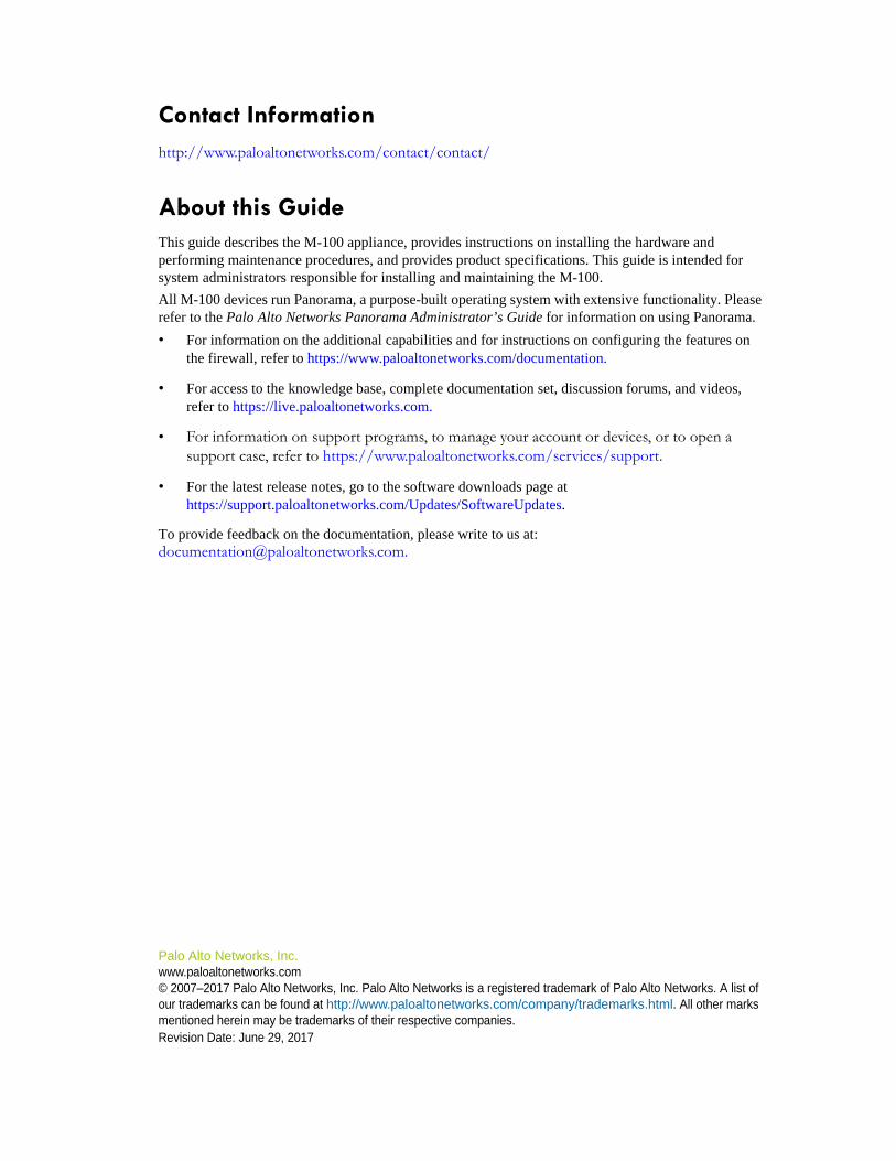
Contact Informationhttp://www.paloaltonetworks.com/contact/contact/
About this GuideThis guide describes the M-100 appliance, provides instructions on installing the hardware and performing maintenance procedures, and provides product specifications. This guide is intended for system administrators responsible for installing and maintaining the M-100.
All M-100 devices run Panorama, a purpose-built operating system with extensive functionality. Please refer to the Palo Alto Networks Panorama Administrator’s Guide for information on using Panorama.
• For information on the additional capabilities and for instructions on configuring the features on the firewall, refer to https://www.paloaltonetworks.com/documentation.
• For access to the knowledge base, complete documentation set, discussion forums, and videos, refer to https://live.paloaltonetworks.com.
• For information on support programs, to manage your account or devices, or to open a support case, refer to https://www.paloaltonetworks.com/services/support.
• For the latest release notes, go to the software downloads page athttps://support.paloaltonetworks.com/Updates/SoftwareUpdates.
To provide feedback on the documentation, please write to us at: [email protected].
Palo Alto Networks, Inc.www.paloaltonetworks.com© 2007–2017 Palo Alto Networks, Inc. Palo Alto Networks is a registered trademark of Palo Alto Networks. A list of our trademarks can be found at http://www.paloaltonetworks.com/company/trademarks.html. All other marks mentioned herein may be trademarks of their respective companies.Revision Date: June 29, 2017
Palo Alto Networks Table of Contents • 3
June 29, 2017 - Palo Alto Networks COMPANY CONFIDENTIAL
Chapter 1 Overview . . . . . . . . . . . . . . . . . . . . . . . . . . . . . . . . . . . . . . . . . . . . . . . . . . 5
Front Panel . . . . . . . . . . . . . . . . . . . . . . . . . . . . . . . . . . . . . . . . . . . . . . . . . . 6Back Panel . . . . . . . . . . . . . . . . . . . . . . . . . . . . . . . . . . . . . . . . . . . . . . . . . . 8
Chapter 2 Installing the Hardware . . . . . . . . . . . . . . . . . . . . . . . . . . . . . . . . . . . . . . . 9
Tamper Proof Statement. . . . . . . . . . . . . . . . . . . . . . . . . . . . . . . . . . . . . . . . 9Before You Begin . . . . . . . . . . . . . . . . . . . . . . . . . . . . . . . . . . . . . . . . . . . . . 9Equipment Rack Installation. . . . . . . . . . . . . . . . . . . . . . . . . . . . . . . . . . . . . . 10
Connecting Cables to the Device . . . . . . . . . . . . . . . . . . . . . . . . . . . . . . . . . 15
Connecting Power . . . . . . . . . . . . . . . . . . . . . . . . . . . . . . . . . . . . . . . . . . . . . 16
Chapter 3 Service the Hardware. . . . . . . . . . . . . . . . . . . . . . . . . . . . . . . . . . . . . . . . 17
Cautions and Warnings . . . . . . . . . . . . . . . . . . . . . . . . . . . . . . . . . . . . . . . . 17
Replace an M-100 Appliance Disk Drive . . . . . . . . . . . . . . . . . . . . . . . . . . . 18
Interpreting the Port LEDs . . . . . . . . . . . . . . . . . . . . . . . . . . . . . . . . . . . . . . . 22
Chapter 4 Specifications . . . . . . . . . . . . . . . . . . . . . . . . . . . . . . . . . . . . . . . . . . . . . . 23
Physical Specifications . . . . . . . . . . . . . . . . . . . . . . . . . . . . . . . . . . . . . . . . . 23
Interface Specifications. . . . . . . . . . . . . . . . . . . . . . . . . . . . . . . . . . . . . . . . . 24
Electrical Specifications . . . . . . . . . . . . . . . . . . . . . . . . . . . . . . . . . . . . . . . . . 24
Environmental Specifications . . . . . . . . . . . . . . . . . . . . . . . . . . . . . . . . . . . . . 24
Chapter 5 Compliance Statements . . . . . . . . . . . . . . . . . . . . . . . . . . . . . . . . . . . . . . 25
VCCI Statement. . . . . . . . . . . . . . . . . . . . . . . . . . . . . . . . . . . . . . . . . . . . . . . 25
BSMI Statement. . . . . . . . . . . . . . . . . . . . . . . . . . . . . . . . . . . . . . . . . . . . . . . 26
Table of Contents
4 • Table of Contents Palo Alto Networks
Appendix A General Safety Information. . . . . . . . . . . . . . . . . . . . . . . . . . . . . . . . . . . . 27
Other Regulatory Information. . . . . . . . . . . . . . . . . . . . . . . . . . . . . . . . . . . . 29
Palo Alto Networks Overview • 5
Chapter 1 Overview
The Palo Alto Networks M-100 appliance is a multi-function appliance that you can configure for one of the following two modes:
• Panorama mode—Performs both central management and log collection for Palo Alto Networks firewalls. This is the default mode.
• Log Collector mode—Functions as a dedicated Log Collector, which either an M-100 or M-500 appliance in Panorama mode or a Panorama virtual appliance can manage.
Use the following topics to learn about the front and back panel components.
• “Front Panel” in the next section
• “Back Panel” on page 8
Note: The minimum Panorama version that you can install on a M-500 appliance is 7.0.
Front Panel
6 • Overview Palo Alto Networks
Front Panel
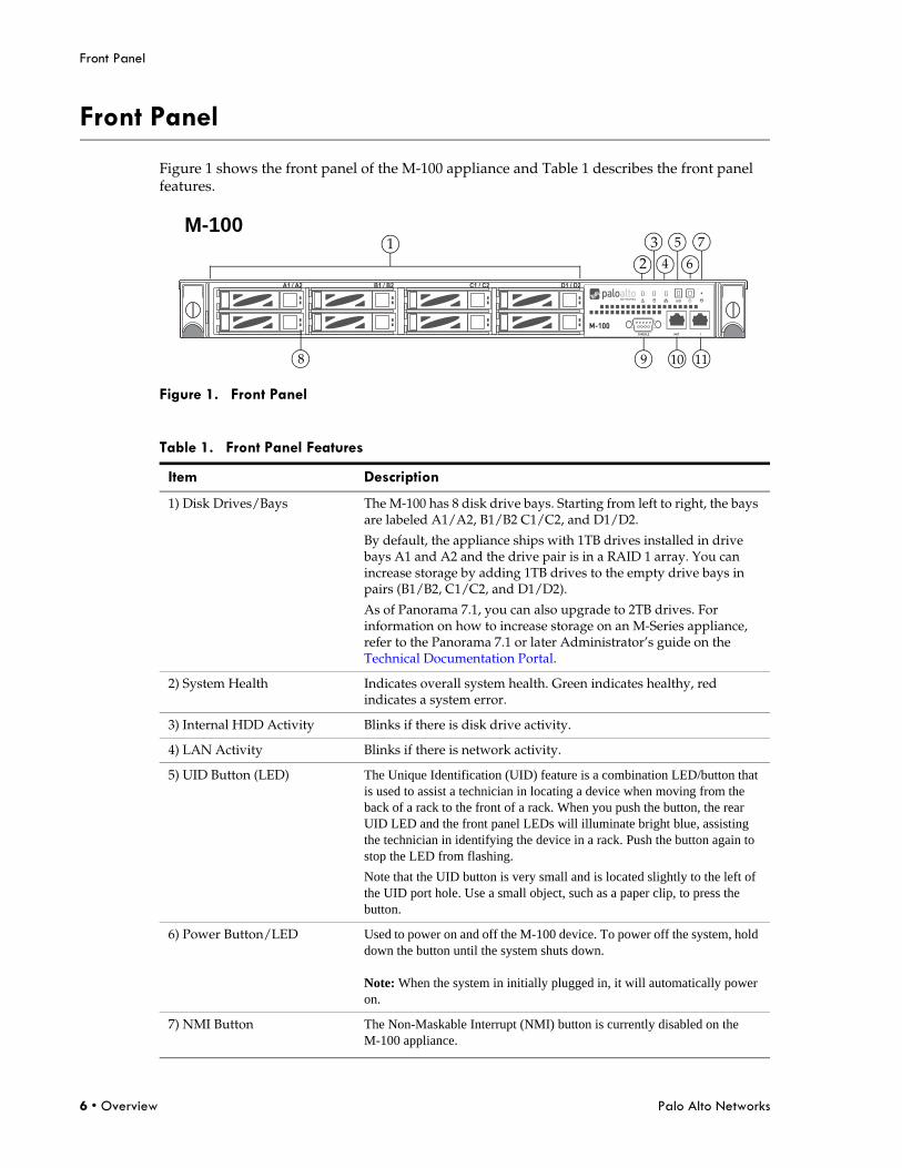
Figure 1 shows the front panel of the M-100 appliance and Table 1 describes the front panel features.
Figure 1. Front Panel
Table 1. Front Panel Features
Item Description
1) Disk Drives/Bays The M-100 has 8 disk drive bays. Starting from left to right, the bays are labeled A1/A2, B1/B2 C1/C2, and D1/D2.
By default, the appliance ships with 1TB drives installed in drive bays A1 and A2 and the drive pair is in a RAID 1 array. You can increase storage by adding 1TB drives to the empty drive bays in pairs (B1/B2, C1/C2, and D1/D2).
As of Panorama 7.1, you can also upgrade to 2TB drives. For information on how to increase storage on an M-Series appliance, refer to the Panorama 7.1 or later Administrator’s guide on the Technical Documentation Portal.
2) System Health Indicates overall system health. Green indicates healthy, red indicates a system error.
3) Internal HDD Activity Blinks if there is disk drive activity.
4) LAN Activity Blinks if there is network activity.
5) UID Button (LED) The Unique Identification (UID) feature is a combination LED/button that is used to assist a technician in locating a device when moving from the back of a rack to the front of a rack. When you push the button, the rear UID LED and the front panel LEDs will illuminate bright blue, assisting the technician in identifying the device in a rack. Push the button again to stop the LED from flashing.
Note that the UID button is very small and is located slightly to the left of the UID port hole. Use a small object, such as a paper clip, to press the button.
6) Power Button/LED Used to power on and off the M-100 device. To power off the system, hold down the button until the system shuts down. Note: When the system in initially plugged in, it will automatically power on.
7) NMI Button The Non-Maskable Interrupt (NMI) button is currently disabled on the M-100 appliance.
D1 / D2C1 / C2B1 / B2A1 / A2
12
34
5
6
7
8 9 10
M-100
11
Palo Alto Networks Overview • 7
Front Panel
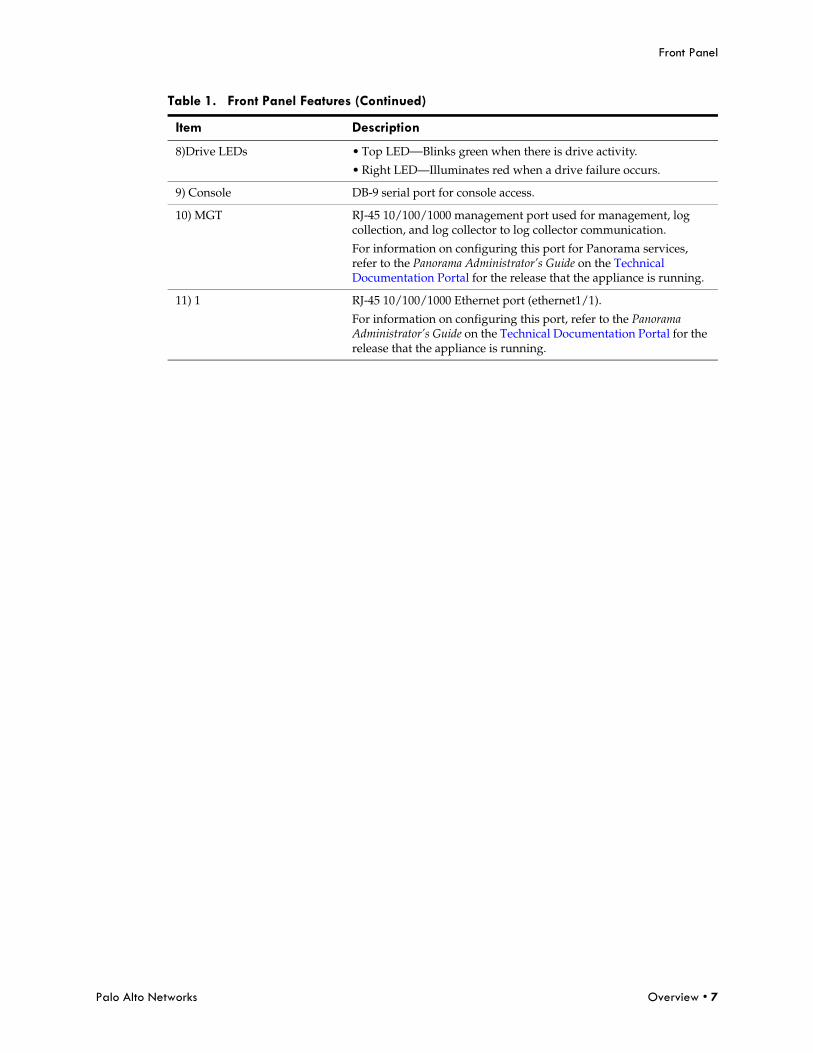
8)Drive LEDs • Top LED—Blinks green when there is drive activity.
• Right LED—Illuminates red when a drive failure occurs.
9) Console DB-9 serial port for console access.
10) MGT RJ-45 10/100/1000 management port used for management, log collection, and log collector to log collector communication.
For information on configuring this port for Panorama services, refer to the Panorama Administrator’s Guide on the Technical Documentation Portal for the release that the appliance is running.
11) 1 RJ-45 10/100/1000 Ethernet port (ethernet1/1).
For information on configuring this port, refer to the Panorama Administrator’s Guide on the Technical Documentation Portal for the release that the appliance is running.
Table 1. Front Panel Features (Continued)
Item Description
Back Panel
8 • Overview Palo Alto Networks
Back Panel
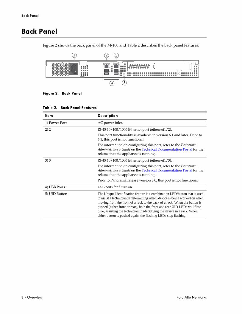
Figure 2 shows the back panel of the M-100 and Table 2 describes the back panel features.
Figure 2. Back Panel
Table 2. Back Panel Features
Item Description
1) Power Port AC power inlet.
2) 2 RJ-45 10/100/1000 Ethernet port (ethernet1/2).
This port functionality is available in version 6.1 and later. Prior to 6.1, this port is not functional.
For information on configuring this port, refer to the Panorama Administrator’s Guide on the Technical Documentation Portal for the release that the appliance is running.
3) 3 RJ-45 10/100/1000 Ethernet port (ethernet1/3).
For information on configuring this port, refer to the Panorama Administrator’s Guide on the Technical Documentation Portal for the release that the appliance is running.
Prior to Panorama release version 8.0, this port is not functional.
4) USB Ports USB ports for future use.
5) UID Button The Unique Identification feature is a combination LED/button that is used to assist a technician in determining which device is being worked on when moving from the front of a rack to the back of a rack. When the button is pushed (either front or rear), both the front and rear UID LEDs will flash blue, assisting the technician in identifying the device in a rack. When either button is pushed again, the flashing LEDs stop flashing.
UID
1 2 3
4 5
Palo Alto Networks Installing the Hardware • 9
Tamper Proof Statement
Chapter 2 Installing the Hardware
This chapter describes how to install the M-100. For more information, refer to the following topics:
• “Tamper Proof Statement” on page 9
• “Before You Begin” in the next section
• “Equipment Rack Installation” on page 10
• “Connecting Cables to the Device” on page 15
• “Connecting Power” on page 16
Tamper Proof Statement
To ensure that products purchased from Palo Alto Networks have not been tampered with during shipping, verify the following upon receipt of each product:
• The tracking number provided to you electronically when ordering the product matches the tracking number that is physically labeled on the box.
• The integrity of the tamper-proof tape used to seal the box is not compromised.
• The integrity of the warranty label on the appliance is not compromised.
Before You Begin
• It is recommended that two people be available to mount the M-100 in a 19-inch rack.
• Have a Phillips head screwdriver available and a small pliers or nut wrench.
• Verify that the intended location has adequate air circulation and meets the temperature requirements. Refer “Environmental Specifications” on page 24.
• Unpack the device.
• Verify that power is not connected to the appliance.
• Allow clear space on both sides of the appliance.
Equipment Rack Installation
10 • Installing the Hardware Palo Alto Networks
Equipment Rack Installation
The M-100 rack mount kit is ordered separately and can be used to mount the M-100 on a 2-post or 4-post 19” rack.
The following safety guidelines apply to rack installation:
• Elevated ambient operating temperature—If the M-100 is installed in a closed or multi-unit rack assembly, the ambient operating temperature of the rack environment may be greater than the ambient room temperature. Verify that the ambient temperature of the rack assembly meets the maximum rated ambient temperature requirements listed in “Environmental Specifications” on page 24.
• Reduced air flow—Ensure that the airflow required for safe device operation is not compromised by the rack installation.
• Mechanical loading—Ensure that the rack-mounted device does not cause hazardous conditions due to uneven mechanical loading.
• Circuit overloading—Ensure that the circuit that supplies power to the device is sufficiently rated to avoid circuit overloading or excess load on supply wiring. Refer to “Electrical Specifications” on page 24.
• Reliable earthing—Maintain reliable earthing of rack mounted equipment. Pay special attention to supply connections other than direct connections to the branch circuit (such as the use of power strips).
To install the M-100 in a grounded 19-inch rack:
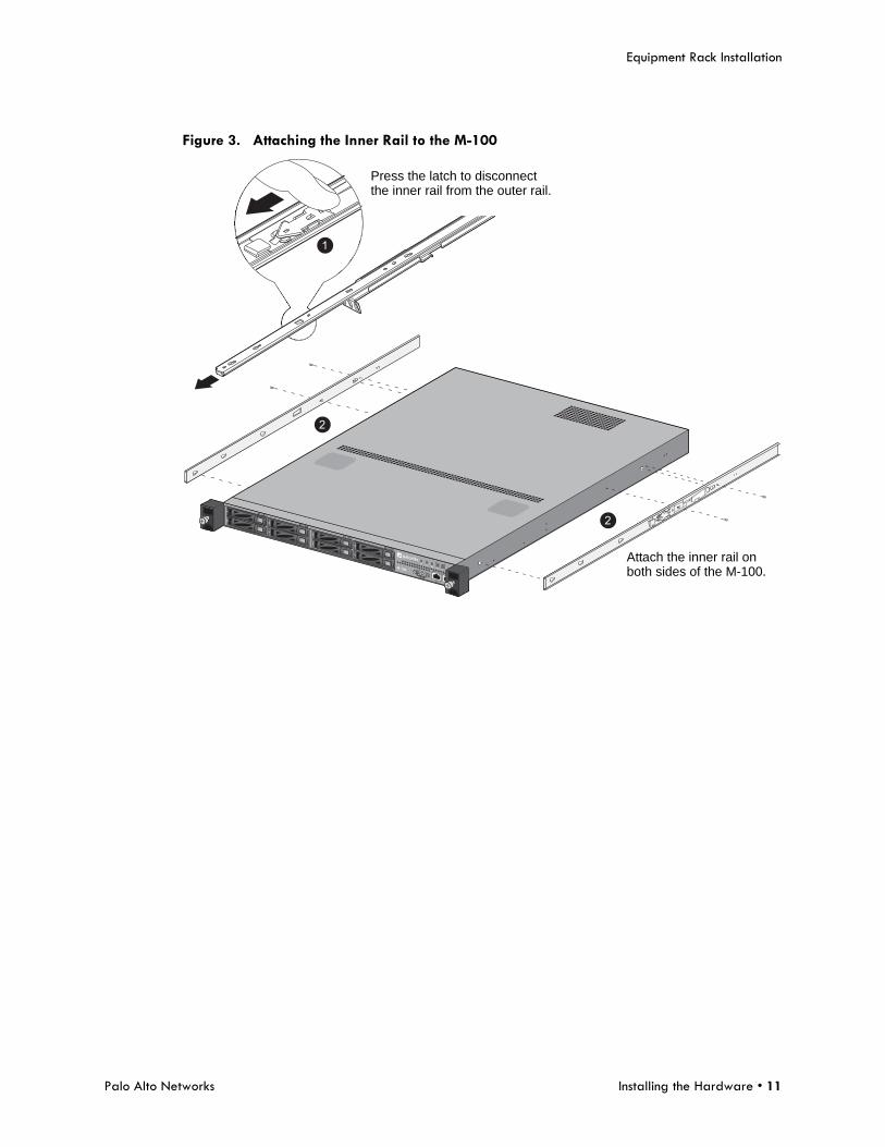
1. Unpack the rail kit and then remove the inner rail from the outer rail and attached the inner rail to both sides of the M-100. To do this, place the inner rail over the mounting posts and then slide forward to lock in place. Simultaneously press the inner rail release latches to allow the inner rail to slide out of the outer rail. The mounting screw holes are now exposed so you can use the provided screws to secure the inner rail to the M-100 as shown in Figure 3.
Palo Alto Networks Installing the Hardware • 11
Equipment Rack Installation
Figure 3. Attaching the Inner Rail to the M-100
1
2
2
Attach the inner rail onboth sides of the M-100.
Press the latch to disconnectthe inner rail from the outer rail.
Equipment Rack Installation
12 • Installing the Hardware Palo Alto Networks
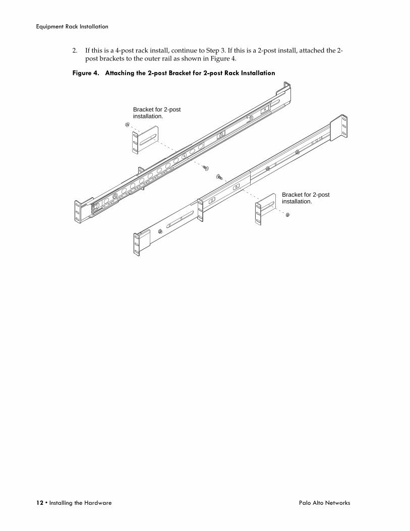
2. If this is a 4-post rack install, continue to Step 3. If this is a 2-post install, attached the 2-post brackets to the outer rail as shown in Figure 4.
Figure 4. Attaching the 2-post Bracket for 2-post Rack Installation
Bracket for 2-postinstallation.
Bracket for 2-postinstallation.
Palo Alto Networks Installing the Hardware • 13
Equipment Rack Installation
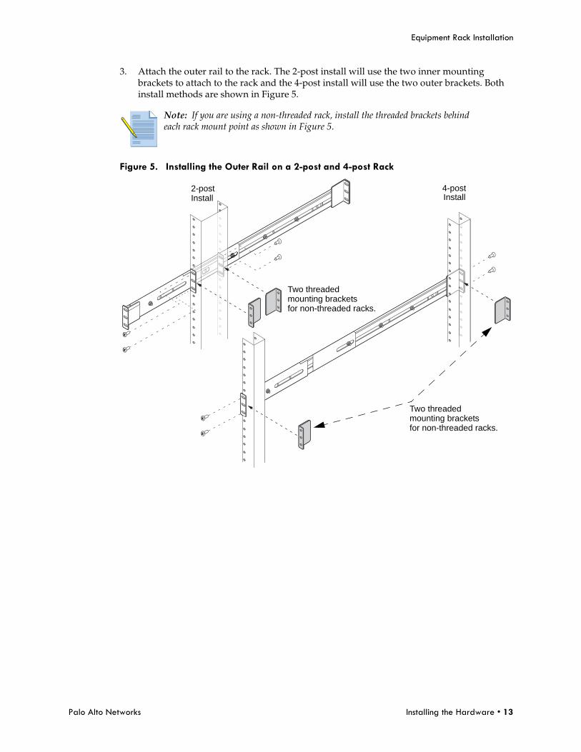
3. Attach the outer rail to the rack. The 2-post install will use the two inner mounting brackets to attach to the rack and the 4-post install will use the two outer brackets. Both install methods are shown in Figure 5.
Figure 5. Installing the Outer Rail on a 2-post and 4-post Rack
Note: If you are using a non-threaded rack, install the threaded brackets behind each rack mount point as shown in Figure 5.
2-post
Two threaded
4-postInstall
mounting bracketsfor non-threaded racks.
Install
Two threadedmounting bracketsfor non-threaded racks.
Equipment Rack Installation
14 • Installing the Hardware Palo Alto Networks
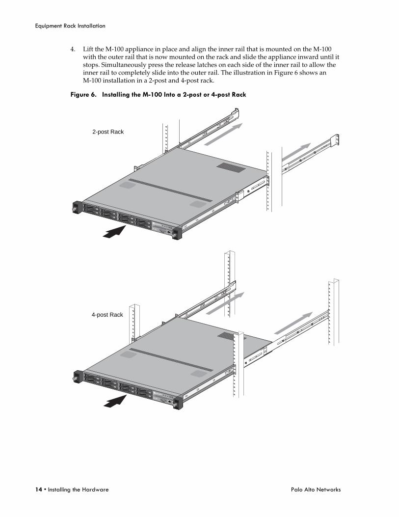
4. Lift the M-100 appliance in place and align the inner rail that is mounted on the M-100 with the outer rail that is now mounted on the rack and slide the appliance inward until it stops. Simultaneously press the release latches on each side of the inner rail to allow the inner rail to completely slide into the outer rail. The illustration in Figure 6 shows an M-100 installation in a 2-post and 4-post rack.
Figure 6. Installing the M-100 Into a 2-post or 4-post Rack
2-post Rack
4-post Rack
Palo Alto Networks Installing the Hardware • 15
Connecting Cables to the Device
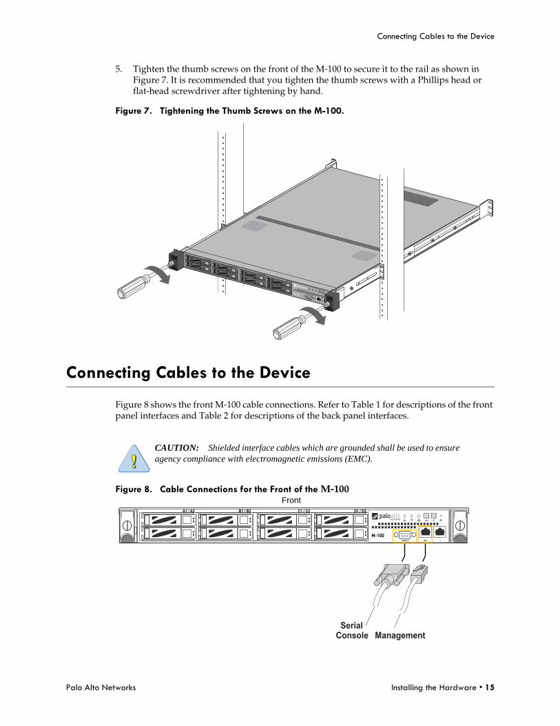
5. Tighten the thumb screws on the front of the M-100 to secure it to the rail as shown in Figure 7. It is recommended that you tighten the thumb screws with a Phillips head or flat-head screwdriver after tightening by hand.
Figure 7. Tightening the Thumb Screws on the M-100.
Connecting Cables to the Device
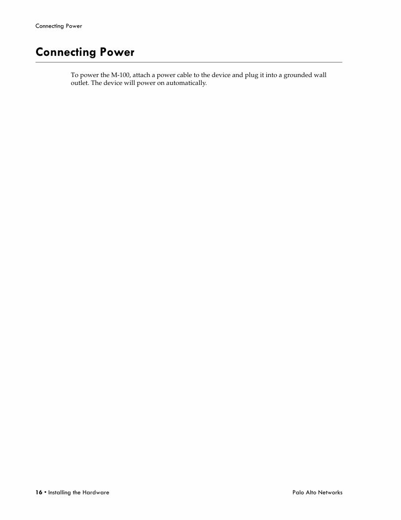
Figure 8 shows the front M-100 cable connections. Refer to Table 1 for descriptions of the front panel interfaces and Table 2 for descriptions of the back panel interfaces.
Figure 8. Cable Connections for the Front of the M-100
CAUTION: Shielded interface cables which are grounded shall be used to ensure agency compliance with electromagnetic emissions (EMC).
D1 / D2C1 / C2B1 / B2A1 / A2
ManagementConsoleSerial
Front
Connecting Power
16 • Installing the Hardware Palo Alto Networks
Connecting Power
To power the M-100, attach a power cable to the device and plug it into a grounded wall outlet. The device will power on automatically.
Palo Alto Networks Service the Hardware • 17
Cautions and Warnings
Chapter 3 Service the Hardware
This chapter describes how to replace disk drives, interpret LEDs, and troubleshoot hardware problems. For more information, refer to the following topics:
• “Cautions and Warnings” in the next section
• “Replace an M-100 Appliance Disk Drive” on page 18
• “Interpreting the Port LEDs” on page 22
Cautions and Warnings
CAUTION: Disconnect all power cords before servicing the M-100.
WARNING: Risk of explosion if battery is replaced by an incorrect type. Dispose of used batteries according to the battery manufacturer’s instructions.
WARNING: Removal of the equipment’s top cover is to be done only by Palo Alto Networks trained service person(s).
Replace an M-100 Appliance Disk Drive
18 • Service the Hardware Palo Alto Networks
Replace an M-100 Appliance Disk Drive
The M-100 appliance has eight drive bays and each drive pair (A1 and A2 for example) is in an independent RAID 1 array. This redundant configuration ensures that there is no service interruption or loss of log data if a disk drive fails.
1. Place an anti-static wrist strap around your wrist and connect it to ground.
2. Identify the failed drive and note the drive model by running the following operational command and viewing the status and model fields:admin@M-100> show system raid detailFor example, the following output shows that disk drive A2 failed and the drive model is ST91000640NS.Disk Pair A Available Status clean, degraded Disk id A1 Present model : ST91000640NS size : 953869 MB status : active sync Disk id A2 Present model : ST91000640NS size : 953869 MB status : failed
3. Remove the failed drive from the RAID 1 array. In this example, run the following command to remove drive A2 from the array:admin@M-100> request system raid remove A2
CAUTION: Do not attempt to replace a drive with a third-party drive. Also, do not mix drive models within a RAID 1 array (for example, the drive model must be the same for both drives in the A1/A2 RAID 1 array). You can, however, mix drive models in different RAID 1 arrays. For example, the drives in the A1/A2 array can both be model ST91000640NS and the drives in the B1/B2 array can both be model ST1000NX0423.
Palo Alto Networks Service the Hardware • 19
Replace an M-100 Appliance Disk Drive
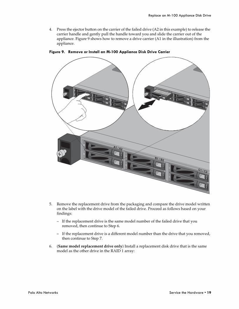
4. Press the ejector button on the carrier of the failed drive (A2 in this example) to release the carrier handle and gently pull the handle toward you and slide the carrier out of the appliance. Figure 9 shows how to remove a drive carrier (A1 in the illustration) from the appliance.
Figure 9. Remove or Install an M-100 Appliance Disk Drive Carrier
5. Remove the replacement drive from the packaging and compare the drive model written on the label with the drive model of the failed drive. Proceed as follows based on your findings:
– If the replacement drive is the same model number of the failed drive that you removed, then continue to Step 6.
– If the replacement drive is a different model number than the drive that you removed, then continue to Step 7.
6. (Same model replacement drive only) Install a replacement disk drive that is the same model as the other drive in the RAID 1 array:
Replace an M-100 Appliance Disk Drive
20 • Service the Hardware Palo Alto Networks
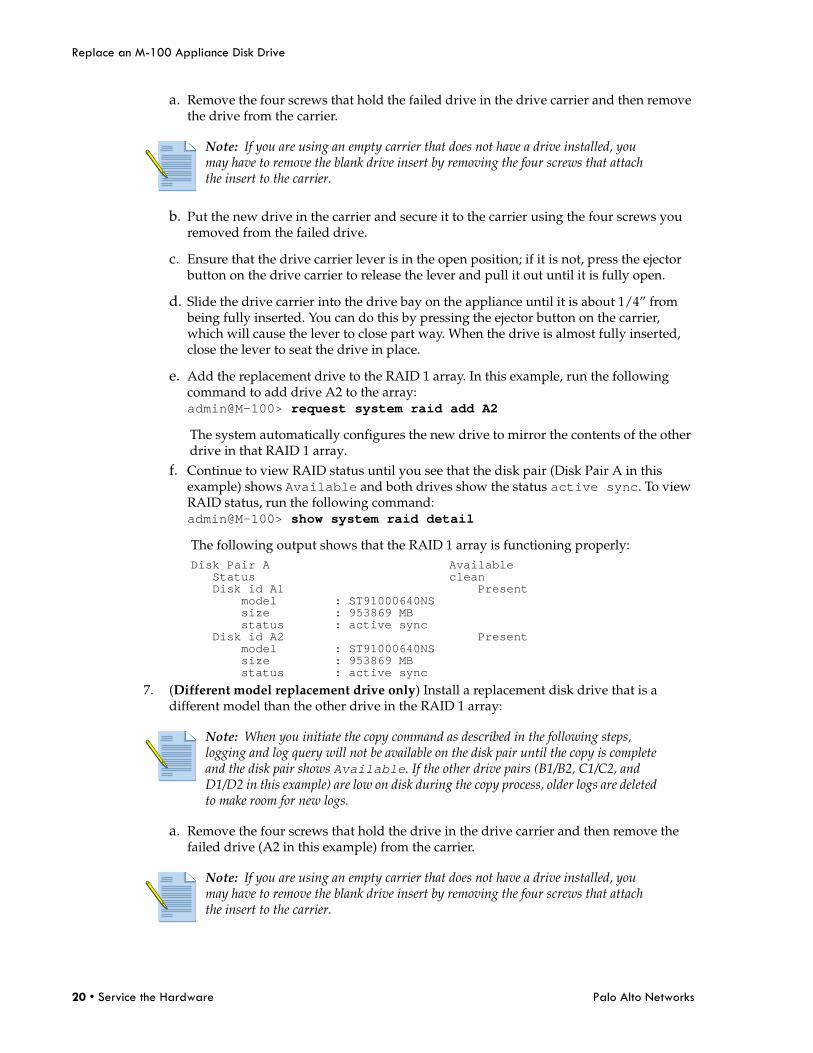
a. Remove the four screws that hold the failed drive in the drive carrier and then remove the drive from the carrier.
b. Put the new drive in the carrier and secure it to the carrier using the four screws you removed from the failed drive.
c. Ensure that the drive carrier lever is in the open position; if it is not, press the ejector button on the drive carrier to release the lever and pull it out until it is fully open.
d. Slide the drive carrier into the drive bay on the appliance until it is about 1/4” from being fully inserted. You can do this by pressing the ejector button on the carrier, which will cause the lever to close part way. When the drive is almost fully inserted, close the lever to seat the drive in place.
e. Add the replacement drive to the RAID 1 array. In this example, run the following command to add drive A2 to the array:admin@M-100> request system raid add A2The system automatically configures the new drive to mirror the contents of the other drive in that RAID 1 array.
f. Continue to view RAID status until you see that the disk pair (Disk Pair A in this example) shows Available and both drives show the status active sync. To view RAID status, run the following command:admin@M-100> show system raid detailThe following output shows that the RAID 1 array is functioning properly:Disk Pair A Available Status clean Disk id A1 Present model : ST91000640NS size : 953869 MB status : active sync Disk id A2 Present model : ST91000640NS size : 953869 MB status : active sync
7. (Different model replacement drive only) Install a replacement disk drive that is a different model than the other drive in the RAID 1 array:
a. Remove the four screws that hold the drive in the drive carrier and then remove the failed drive (A2 in this example) from the carrier.
Note: If you are using an empty carrier that does not have a drive installed, you may have to remove the blank drive insert by removing the four screws that attach the insert to the carrier.
Note: When you initiate the copy command as described in the following steps, logging and log query will not be available on the disk pair until the copy is complete and the disk pair shows Available. If the other drive pairs (B1/B2, C1/C2, and D1/D2 in this example) are low on disk during the copy process, older logs are deleted to make room for new logs.
Note: If you are using an empty carrier that does not have a drive installed, you may have to remove the blank drive insert by removing the four screws that attach the insert to the carrier.
Palo Alto Networks Service the Hardware • 21
Replace an M-100 Appliance Disk Drive
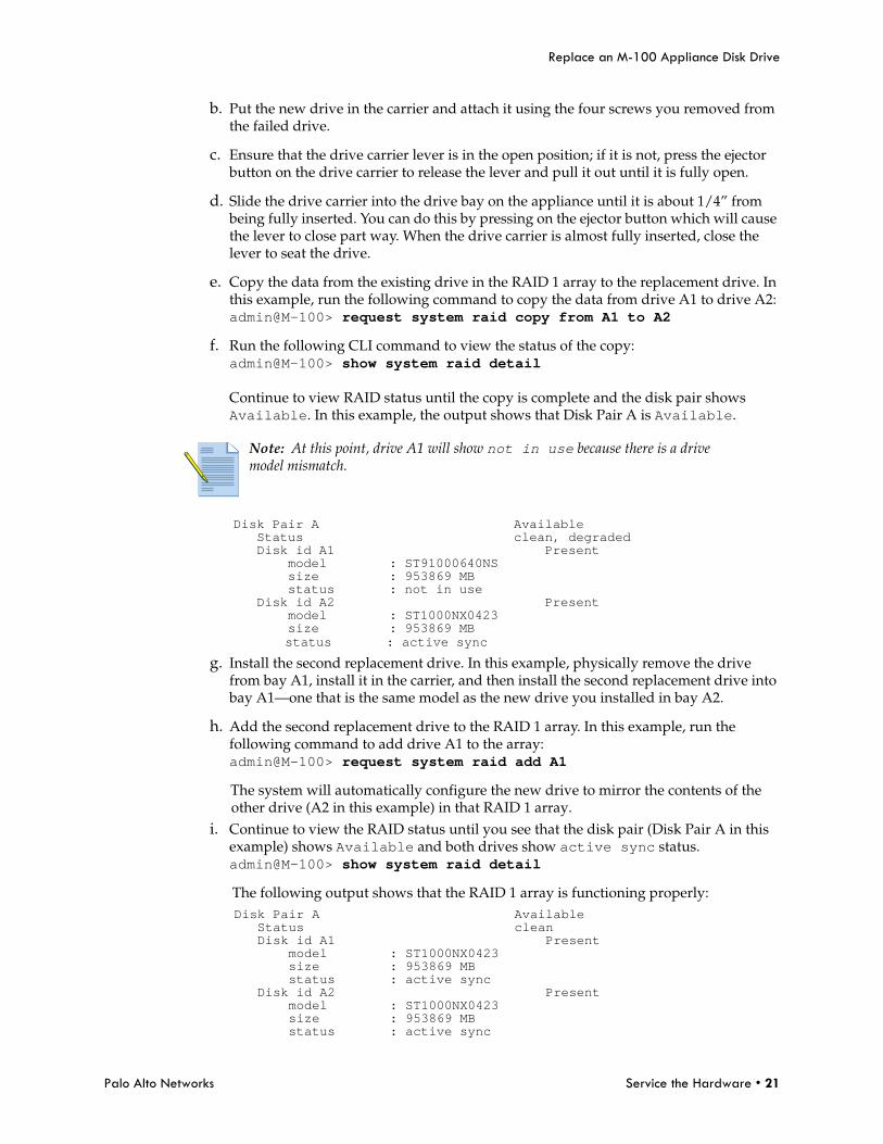
b. Put the new drive in the carrier and attach it using the four screws you removed from the failed drive.
c. Ensure that the drive carrier lever is in the open position; if it is not, press the ejector button on the drive carrier to release the lever and pull it out until it is fully open.
d. Slide the drive carrier into the drive bay on the appliance until it is about 1/4” from being fully inserted. You can do this by pressing on the ejector button which will cause the lever to close part way. When the drive carrier is almost fully inserted, close the lever to seat the drive.
e. Copy the data from the existing drive in the RAID 1 array to the replacement drive. In this example, run the following command to copy the data from drive A1 to drive A2:admin@M-100> request system raid copy from A1 to A2
f. Run the following CLI command to view the status of the copy:admin@M-100> show system raid detailContinue to view RAID status until the copy is complete and the disk pair shows Available. In this example, the output shows that Disk Pair A is Available.
Disk Pair A Available Status clean, degraded Disk id A1 Present model : ST91000640NS size : 953869 MB status : not in use Disk id A2 Present model : ST1000NX0423 size : 953869 MB status : active sync
g. Install the second replacement drive. In this example, physically remove the drive from bay A1, install it in the carrier, and then install the second replacement drive into bay A1—one that is the same model as the new drive you installed in bay A2.
h. Add the second replacement drive to the RAID 1 array. In this example, run the following command to add drive A1 to the array:admin@M-100> request system raid add A1The system will automatically configure the new drive to mirror the contents of the other drive (A2 in this example) in that RAID 1 array.
i. Continue to view the RAID status until you see that the disk pair (Disk Pair A in this example) shows Available and both drives show active sync status.admin@M-100> show system raid detailThe following output shows that the RAID 1 array is functioning properly:Disk Pair A Available Status clean Disk id A1 Present model : ST1000NX0423 size : 953869 MB status : active sync Disk id A2 Present model : ST1000NX0423 size : 953869 MB status : active sync
Note: At this point, drive A1 will show not in use because there is a drive model mismatch.
Interpreting the Port LEDs
22 • Service the Hardware Palo Alto Networks
Interpreting the Port LEDs
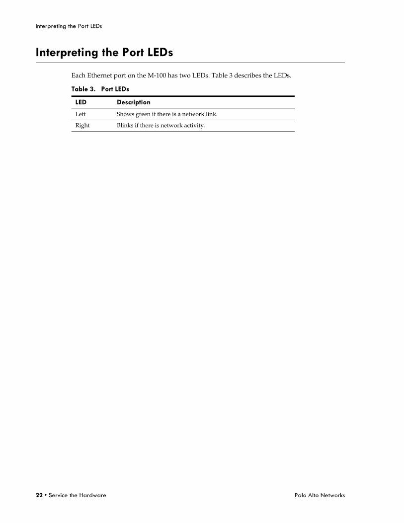
Each Ethernet port on the M-100 has two LEDs. Table 3 describes the LEDs.
Table 3. Port LEDs
LED Description
Left Shows green if there is a network link.
Right Blinks if there is network activity.
Palo Alto Networks Specifications • 23
Physical Specifications
Chapter 4 Specifications
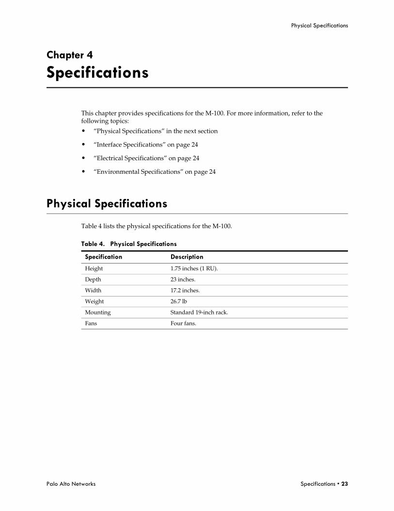
This chapter provides specifications for the M-100. For more information, refer to the following topics:
• “Physical Specifications” in the next section
• “Interface Specifications” on page 24
• “Electrical Specifications” on page 24
• “Environmental Specifications” on page 24
Physical Specifications
Table 4 lists the physical specifications for the M-100.
Table 4. Physical Specifications
Specification Description
Height 1.75 inches (1 RU).
Depth 23 inches.
Width 17.2 inches.
Weight 26.7 lb
Mounting Standard 19-inch rack.
Fans Four fans.
Interface Specifications
24 • Specifications Palo Alto Networks
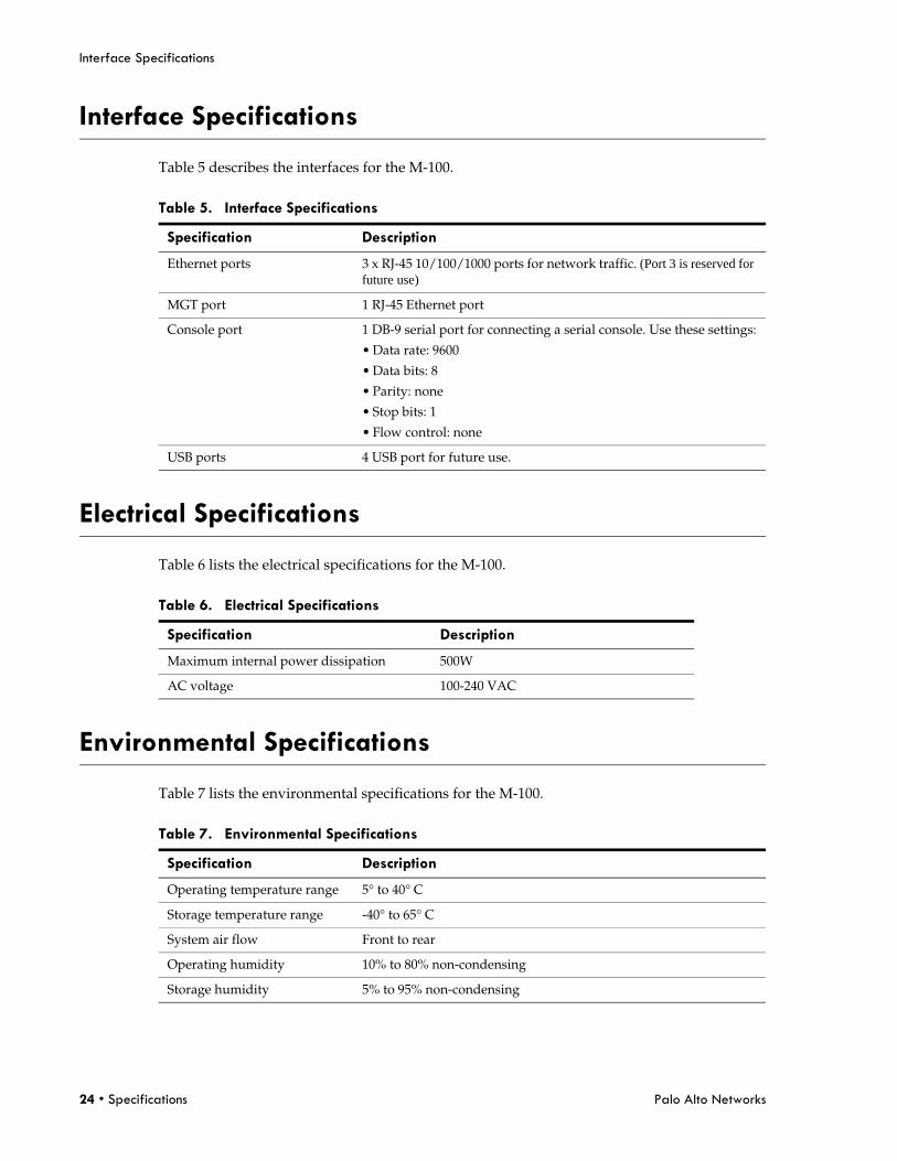
Interface Specifications
Table 5 describes the interfaces for the M-100.
Electrical Specifications
Table 6 lists the electrical specifications for the M-100.
Environmental Specifications
Table 7 lists the environmental specifications for the M-100.
Table 5. Interface Specifications
Specification Description
Ethernet ports 3 x RJ-45 10/100/1000 ports for network traffic. (Port 3 is reserved for future use)
MGT port 1 RJ-45 Ethernet port
Console port 1 DB-9 serial port for connecting a serial console. Use these settings:
• Data rate: 9600
• Data bits: 8
• Parity: none
• Stop bits: 1
• Flow control: none
USB ports 4 USB port for future use.
Table 6. Electrical Specifications
Specification Description
Maximum internal power dissipation 500W
AC voltage 100-240 VAC
Table 7. Environmental Specifications
Specification Description
Operating temperature range 5° to 40° C
Storage temperature range -40° to 65° C
System air flow Front to rear
Operating humidity 10% to 80% non-condensing
Storage humidity 5% to 95% non-condensing
Palo Alto Networks Compliance Statements • 25
VCCI Statement
Chapter 5 Compliance Statements
This topic lists the M-100 appliance hardware compliance statements.
• “VCCI Statement” on page 25
• “BSMI Statement” on page 26
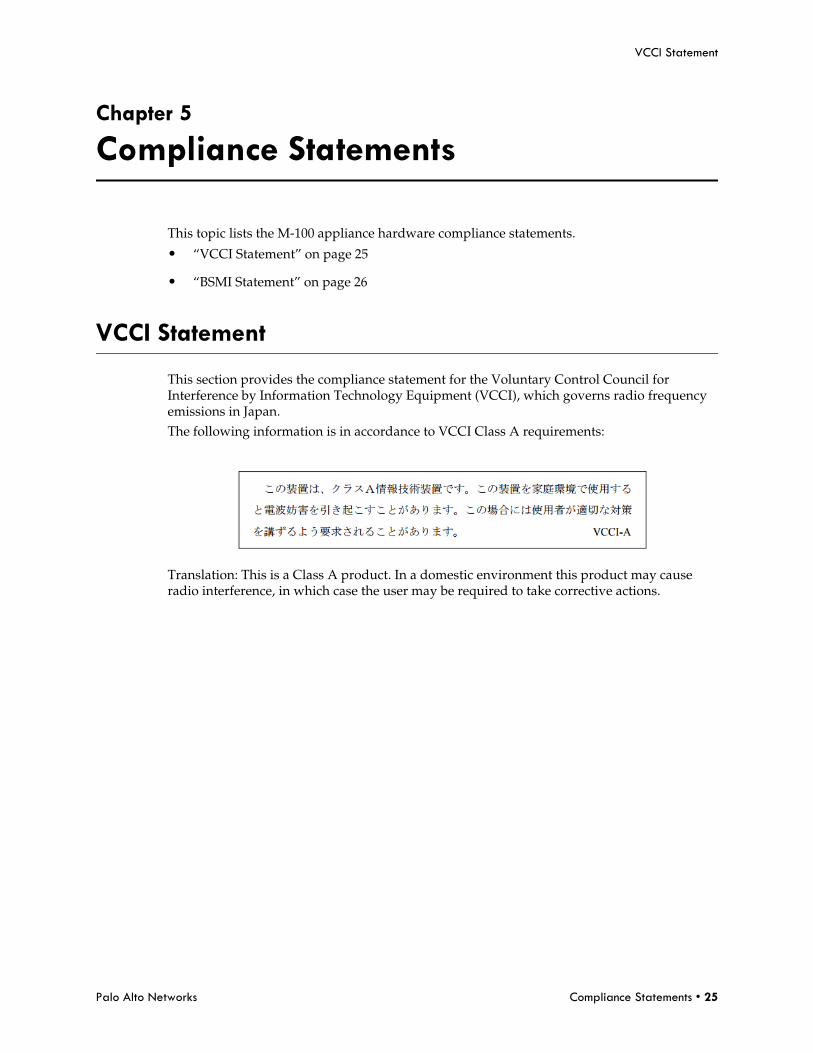
VCCI Statement
This section provides the compliance statement for the Voluntary Control Council for Interference by Information Technology Equipment (VCCI), which governs radio frequency emissions in Japan. The following information is in accordance to VCCI Class A requirements:
Translation: This is a Class A product. In a domestic environment this product may cause radio interference, in which case the user may be required to take corrective actions.
BSMI Statement
26 • Compliance Statements Palo Alto Networks
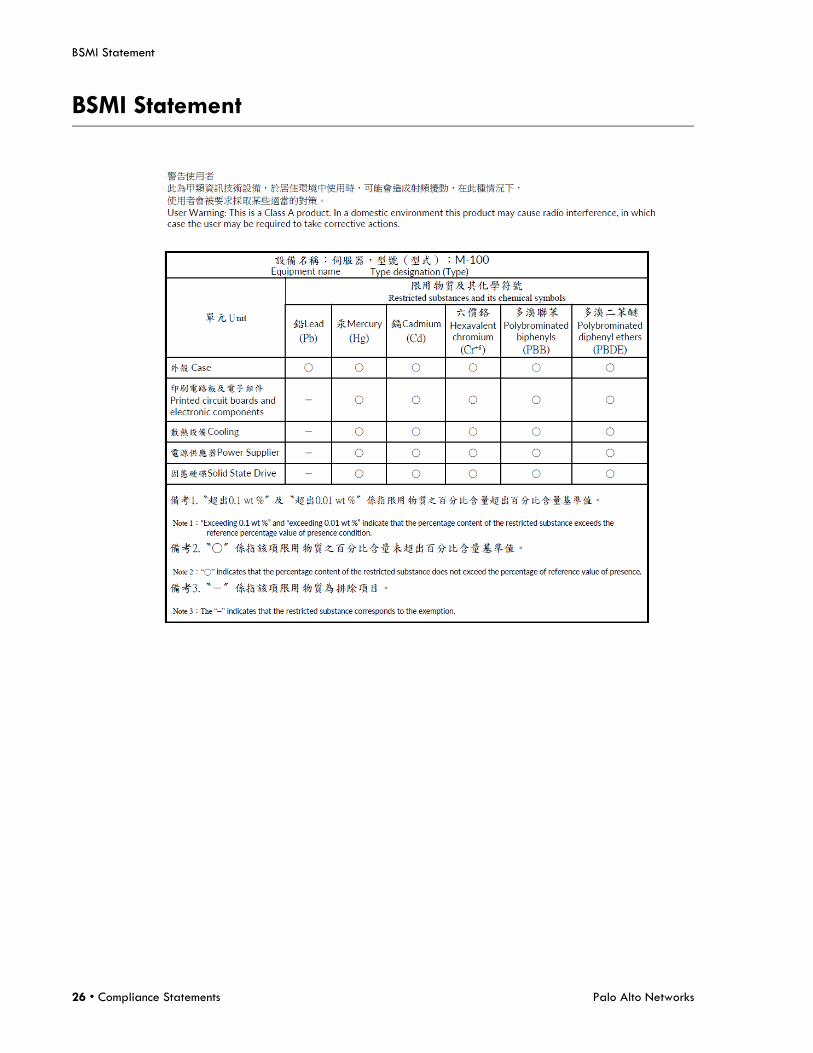
BSMI Statement
Palo Alto Networks • 27
Appendix A General Safety Information
1. The M-100 should not be used in a home, school or other public area where the general population would have access to it.
2. The manufacturer specifies that the thumbscrew should be tightened with a screwdriver. Use of a thumbscrew is not to compromise the basic principles of safety.
• Do not use damaged equipment, including exposed, frayed or damaged power cords. Use only the approved power cable that is rated for the equipment. The voltage and current rating of the cable should be greater than the ratings marked on the equipment.
• Plug the power cables into properly grounded electrical outlets. Do not use adapter plugs or remove the grounding prong from a cable.
• Observe extension cable and power strip ratings to ensure that the total ampere rating of all equipment plugged into the extension cable or power strip does not exceed 80 percent of the ampere ratings limit for the extension cable or power strip.
• The power supplies in the M-100 may produce high voltages and potential energy hazards. By opening the cover of the M-100 you may be exposed to a risk of electric shock. The components inside the M-100 housing should only be serviced by Palo Alto Networks.
• The M-100 should not be operated with the cover removed.
• Components inside the M-100 housing may become extremely hot during normal operation. These components include the memory and CPU modules. Allow sufficient time for components to cool before handling.
• The M-100 should not be operated in environments that can get wet. Protect the M-100 at all times from liquid intrusion.
• If your M-100 gets wet, turn off the AC power at the circuit breaker before attempting to remove the power cables from the electrical outlet. Then disconnect power to the equipment and to any attached devices.
CAUTION
Please Note the Following:
WARNING
To prevent the potential for personal injury, property damage, or death, please observe the following instructions:
28 • Palo Alto Networks
• Avoid obstructing the air vents on the M-100 or pushing objects into the openings. This could lead to fire or electric shock.
• Follow installation instructions carefully.
• Do not attempt to service the equipment yourself.
• You should operate this equipment from the type of external power source indicated on the electrical ratings label.
• Wait 30 seconds after turning off the equipment before removing a component from the system or disconnecting a peripheral device from the M-100.
• Always leave at least 4 inches (10.2cm) of physical clearance on all vented sides of the M-100. This permits the airflow required for proper ventilation.
• Avoid placing equipment too close together such that it is subject to re-circulated (pre-heated) air. Avoid placing equipment too close to an appliance or exhaust vent.
• Ensure that cables are connected to the M-100 without stress and that nothing rests on the cables.
• If the equipment is located in a rack, move it with caution. Ensure that all casters and/or stabilizers are firmly connected. While moving the equipment, avoid uneven surfaces and sudden stops.
• Do not place other equipment, monitors, or other devices on top of the M-100.
• To protect the M-100 from fluctuations in electrical power, use a surge suppressor, line conditioner or uninterruptible power supply (UPS).
• Slide rail mounted equipment is not to be used as a shelf or a work space.
• Elevated Operating Ambient – If the M-100 is installed in a closed or multi-unit rack assembly, the operating ambient temperature in the rack environment may be greater than the room ambient temperature. Therefore, consideration should be given to the maximum operating temperature specified in “Environmental Specifications” on page 24.
• Reduced Air Flow – Installation of the M-100 in a rack should be such that the amount of air flow required for safe operation is not compromised.
• Mechanical Loading – Mounting of the M-100 in the rack should not create a hazardous condition from uneven mechanical loading.
• Circuit Overloading – Connection of the equipment to the supply circuit should not create an overloaded situation. Pay close attention to equipment nameplate ratings.
CAUTION
To prevent hardware damage or loss of data, observe the following precautions:
CAUTION
Please observe the following additional precautions for rack-mounted systems:
Palo Alto Networks • 29
Other Regulatory Information
• Reliable Grounding – Devices mounted in racks should be grounded properly. If using power strips to connect the M-100 to the supply circuit, make certain that the power strips are also grounded properly.
• It is your responsibility to ensure that the rack and the provided rail system are compatible with each other before installing the M-100.
• Install the front and side stabilizers on the rack prior to installing equipment. Failure to install stabilizers may cause a rack to tip over.
• Load racks from the bottom up, loading the heaviest items near the bottom of the rack.
• Do not stand or step on components in the rack.
• Grounding techniques may vary. However, a positive connection to a safety (earth) ground is required.
• Make the ground connection first and disconnect it last to prevent hazards.
• Never defeat the ground conductor or operate the equipment in the absence of a suitably installed ground conductor.
• If the system is installed in a rack, ensure that the system chassis is securely grounded to the rack cabinet frame. Do not connect power to the system until grounding cables are connected.
Other Regulatory Information
Export Regulations
Customer acknowledges that these Products, which may include technology and software, are subject to the customs and export control laws and regulations of the United States (“U.S.”) and may also be subject to the customs and export laws and regulations of the country in which the Products are manufactured and/or received. Customer agrees to abide by those laws and regulations. Further, under U.S. law, the Products may not be sold, leased or otherwise transferred to restricted end-users or to restricted countries. In addition, the Products may not be sold leased or otherwise transferred to, or utilized by an end-user engaged in activities related to weapons of mass destruction, including without limitation, activities related to the design, development, production or use of nuclear weapons, materials or facilities, missiles or the support of missile projects, and chemical or biological weapons.
WARNING
Grounding Instructions for Qualified Electricians Only:

30 • Palo Alto Networks