Embed Size (px)
Citation preview
AutoCAD®Lynn Allen’s Tips and Tricks for Using AutoCAD 2011
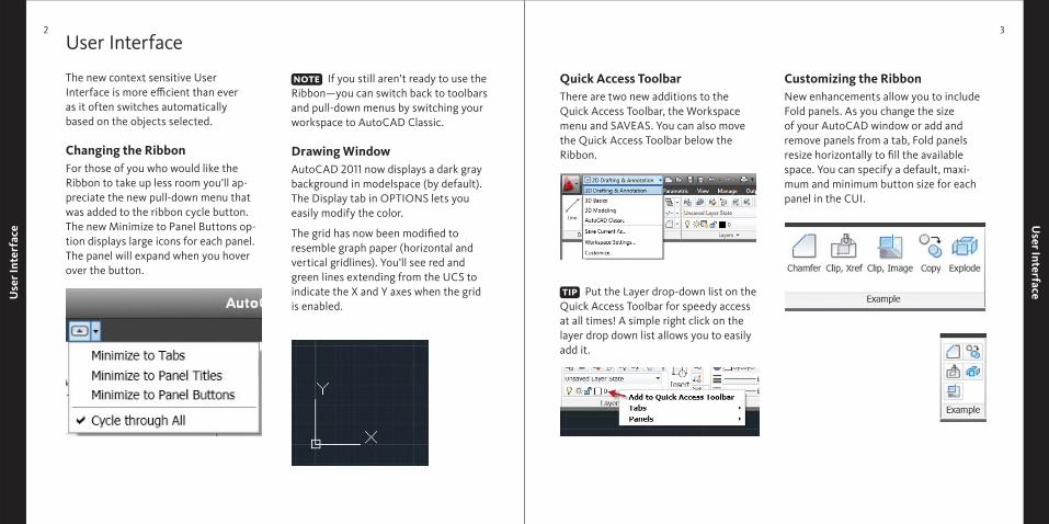
Customizing the RibbonNew enhancements allow you to include Fold panels. As you change the size of your AutoCAD window or add and remove panels from a tab, Fold panels resize horizontally to fi ll the available space. You can specify a default, maxi-mum and minimum button size for each panel in the CUI.
User InterfaceUse
r Int
erfa
ce2 3
User Interface
The new context sensitive User Interface is more effi cient than ever as it often switches automatically based on the objects selected.
Changing the RibbonFor those of you who would like the Ribbon to take up less room you’ll ap-preciate the new pull-down menu that was added to the ribbon cycle button. The new Minimize to Panel Buttons op-tion displays large icons for each panel. The panel will expand when you hover over the button.
If you still aren’t ready to use the Ribbon—you can switch back to toolbars and pull-down menus by switching your workspace to AutoCAD Classic.
Drawing WindowAutoCAD 2011 now displays a dark gray background in modelspace (by default). The Display tab in OPTIONS lets you easily modify the color.
The grid has now been modifi ed to resemble graph paper (horizontal and vertical gridlines). You’ll see red and green lines extending from the UCS to indicate the X and Y axes when the grid is enabled.
Quick Access ToolbarThere are two new additions to the Quick Access Toolbar, the Workspace menu and SAVEAS. You can also move the Quick Access Toolbar below the Ribbon.
Put the Layer drop-down list on the Quick Access Toolbar for speedy access at all times! A simple right click on the layer drop down list allows you to easily add it.
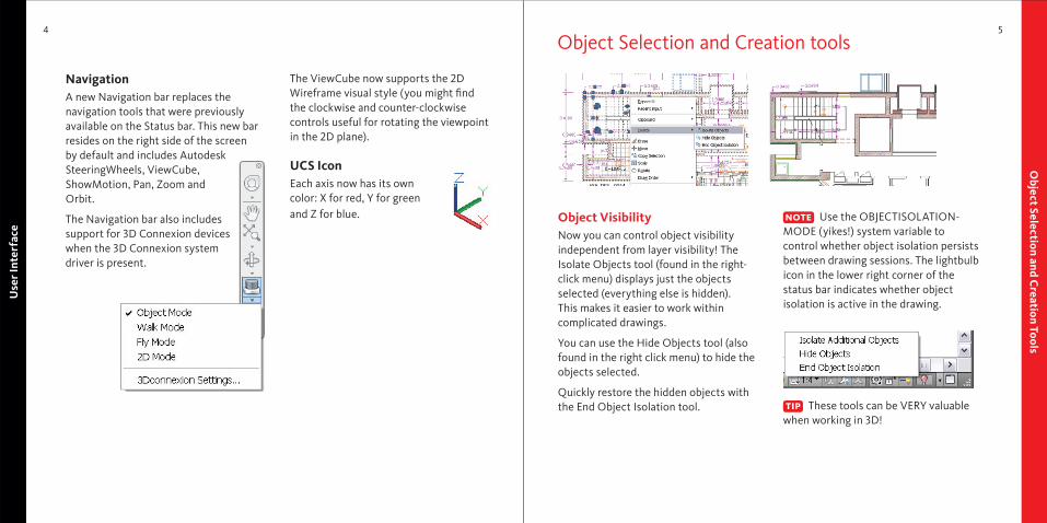
The ViewCube now supports the 2D Wireframe visual style (you might fi nd the clockwise and counter-clockwise controls useful for rotating the viewpoint in the 2D plane).
UCS IconEach axis now has its own color: X for red, Y for green and Z for blue.
Use
r Int
erfa
ce4
Object Selection and C
reation Tools5
NavigationA new Navigation bar replaces the navigation tools that were previously available on the Status bar. This new bar resides on the right side of the screen by default and includes Autodesk SteeringWheels, ViewCube, ShowMotion, Pan, Zoom and Orbit.
The Navigation bar also includes support for 3D Connexion devices when the 3D Connexion system driver is present.
Object VisibilityNow you can control object visibility independent from layer visibility! The Isolate Objects tool (found in the right-click menu) displays just the objects selected (everything else is hidden). This makes it easier to work within complicated drawings.
You can use the Hide Objects tool (also found in the right click menu) to hide the objects selected.
Quickly restore the hidden objects with the End Object Isolation tool.
Use the OBJECTISOLATION-MODE (yikes!) system variable to control whether object isolation persists between drawing sessions. The lightbulb icon in the lower right corner of the status bar indicates whether object isolation is active in the drawing.
These tools can be VERY valuable when working in 3D!
Object Selection and Creation tools
Object Selection and C
reation Tools7
Obj
ect S
elec
tion
and
Cre
atio
n To
ols
6
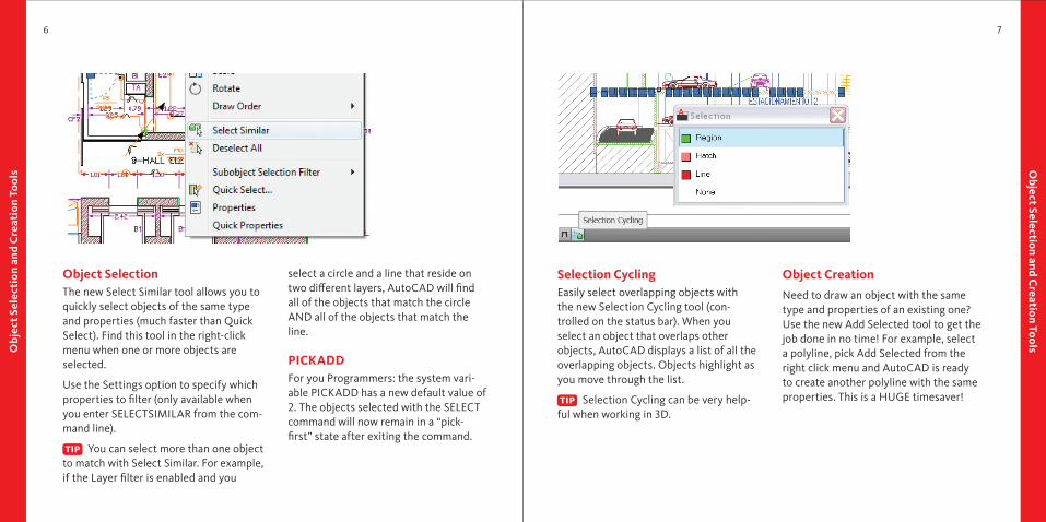
Object SelectionThe new Select Similar tool allows you to quickly select objects of the same type and properties (much faster than Quick Select). Find this tool in the right-click menu when one or more objects are selected.
Use the Settings option to specify which properties to fi lter (only available when you enter SELECTSIMILAR from the com-mand line).
You can select more than one object to match with Select Similar. For example, if the Layer fi lter is enabled and you
select a circle and a line that reside on two diff erent layers, AutoCAD will fi nd all of the objects that match the circle AND all of the objects that match the line.
PICKADDFor you Programmers: the system vari-able PICKADD has a new default value of 2. The objects selected with the SELECT command will now remain in a “pick-fi rst” state after exiting the command.
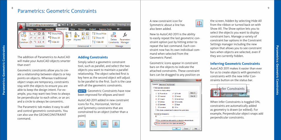
Selection CyclingEasily select overlapping objects with the new Selection Cycling tool (con-trolled on the status bar). When you select an object that overlaps other objects, AutoCAD displays a list of all the overlapping objects. Objects highlight as you move through the list.
Selection Cycling can be very help-ful when working in 3D.
Object Creation
Need to draw an object with the same type and properties of an existing one? Use the new Add Selected tool to get the job done in no time! For example, select a polyline, pick Add Selected from the right click menu and AutoCAD is ready to create another polyline with the same properties. This is a HUGE timesaver!
8
Param
etrics: Geom
etric Constraints
9
The addition of Parametrics to AutoCAD will make your AutoCAD objects smarter than ever!
Geometric constraints allow you to cre-ate a relationship between objects or key points on objects. Whereas traditional object snaps are temporary, constraints stay with the objects to ensure you are able to keep the design intent. For ex-ample, you may want two lines to always be perpendicular to each other, or an arc and a circle to always be concentric.
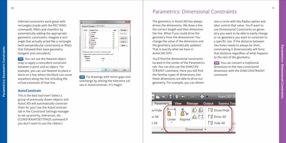
The Parametric tab makes it easy to add and control geometric constraints. You can also use the GEOMCONSTRAINT command.
Adding Constraints Simply select a geometric constraint tool, such as parallel, and select the two objects you want to maintain a parallel relationship. The object selected fi rst is key here as the second object will adjust to be parallel to the fi rst. Such is the case with all the geometric constraints.
Geometric Constraints have now been improved for ellipses and text!
AutoCAD 2011 added in new constraint icons for Fix, Horizontal, Vertical and Symmetry constraints that are constrained to an object (rather than a point)
Parametrics: Geometric Constraints
A new constraint icon for Symmetric about a line has also been added.
New to AutoCAD 2011 is the ability to easily repeat the last geometric con-straint option just by hitting enter to repeat the last command. Each con-straint now has its own individual com-mand when selected from the Geometric Panel.
Geometric icons appear in constraint bars on the objects to indicate the attached constraints. These constraint bars can be dragged to any position on
the screen, hidden by selecting Hide All from the ribbon or turned back on with Show All. The Show option lets you to select the objects you want to display constraint bars. Manage a variety of constraint bar options in the Constraint Settings manager including the new option that allows you to see constraint bars when objects are selected, even if they are currently hidden.
Inferring Geometric ConstraintsAutoCAD 2011 makes it easier than ever for us to create objects with geometric constraints with the new Infer Con-straints button on the status bar.
When Infer Constraints is toggled ON, constraints are automatically added as geometry is drawn (or edited). For example, Perpendicular object snaps add perpendicular constraints.
Par
amet
rics
: Geo
met
ric
Con
stra
ints
Par
amet
rics
: Geo
met
ric
Con
stra
ints
10
Param
etrics: Dim
ensional Constraints
11
Inferred constraints work great with rectangles (made with the RECTANG command), fi llets and chamfers by automatically adding the appropriate geometric constraints. Imagine a rect-angle that actually acted like a rectangle (with perpendicular constraints) or fi llets that followed their base geometry (tangent and coincident).
You can use the Nearest object snap to apply a coincident constraint between a point and an object. For example, you can use Nearest to place a block on a line where the block can move anywhere along the line including the virtual extension of that line.
AutoConstrain This is the best tool ever! Select a group of previously drawn objects and AutoCAD will automatically constrain them for you! Use the AutoConstrain tab in the Constraint Settings manager to set up priority, tolerances, etc. (CONSTRAINTSETTINGS command if you don’t want to use the ribbon.)
Fix drawings with minor gaps and overhangs by setting the tolerance val-ues in AutoConstrain. It’s magic!
Parametrics: Dimensional Constraints
The geometry in AutoCAD has always driven the dimensions. We draw a line the correct length and then dimension the line. What if you could drive the geometry from the dimensions? You change the value of the dimension and the geometry automatically updates! That is exactly what we have in AutoCAD 2011.
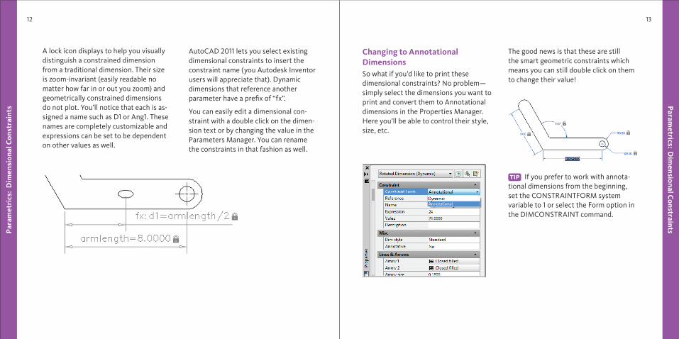
You’ll fi nd the dimensional constraints located in the center of the Parametrics tab. You can also use the DIMCON-STRAINT command. Here you will fi nd the familiar types of dimensions, but these dimensions are able to drive our geometry. For example, you can dimen-
sion a circle with the Radius option and later control that value. You’ll want to use Dimensional Constraints on geom-etry you want to be able to easily change or on geometry you want to constrain to a specifi c size. If the distance between two holes needs to always be 3mm, constraining it dimensionally will force that distance regardless of what happens to the rest of the geometry.
You can convert a traditional dimension to the new constrained dimension with the DIMCONSTRAINT command.
Param
etrics: Dim
ensional Constraints
13
Par
amet
rics
: D
imen
sion
al C
onst
rain
ts
12
A lock icon displays to help you visually distinguish a constrained dimension from a traditional dimension. Their size is zoom-invariant (easily readable no matter how far in or out you zoom) and geometrically constrained dimensions do not plot. You’ll notice that each is as-signed a name such as D1 or Ang1. These names are completely customizable and expressions can be set to be dependent on other values as well.
AutoCAD 2011 lets you select existing dimensional constraints to insert the constraint name (you Autodesk Inventor users will appreciate that). Dynamic dimensions that reference another parameter have a prefi x of “fx”.
You can easily edit a dimensional con-straint with a double click on the dimen-sion text or by changing the value in the Parameters Manager. You can rename the constraints in that fashion as well.
Changing to Annotational DimensionsSo what if you’d like to print these dimensional constraints? No problem— simply select the dimensions you want to print and convert them to Annotational dimensions in the Properties Manager. Here you’ll be able to control their style, size, etc.
The good news is that these are still the smart geometric constraints which means you can still double click on them to change their value!
If you prefer to work with annota-tional dimensions from the beginning, set the CONSTRAINTFORM system variable to 1 or select the Form option in the DIMCONSTRAINT command.
Param
etrics: Dynam
ic Blocks
15
Par
amet
rics
: D
imen
sion
al C
onst
rain
ts
14
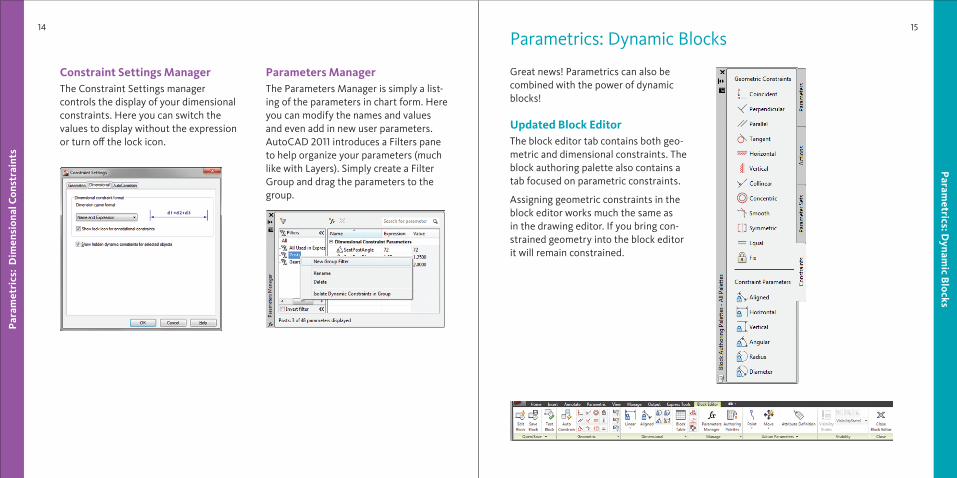
Constraint Settings ManagerThe Constraint Settings manager controls the display of your dimensional constraints. Here you can switch the values to display without the expression or turn off the lock icon.
Parameters ManagerThe Parameters Manager is simply a list-ing of the parameters in chart form. Here you can modify the names and values and even add in new user parameters. AutoCAD 2011 introduces a Filters pane to help organize your parameters (much like with Layers). Simply create a Filter Group and drag the parameters to the group.
Great news! Parametrics can also be combined with the power of dynamic blocks!
Updated Block Editor The block editor tab contains both geo-metric and dimensional constraints. The block authoring palette also contains a tab focused on parametric constraints.
Assigning geometric constraints in the block editor works much the same as in the drawing editor. If you bring con-strained geometry into the block editor it will remain constrained.
Parametrics: Dynamic Blocks
Param
etrics: Dynam
ic Blocks
17
Par
amet
rics
: Dyn
amic
Blo
cks
16
Dimensional ConstraintsDimensional Constraint parameters can be added to dynamic block geometry. Their name is in turn exposed as a prop-erty for the block, much like the stan-dard dynamic block parameters. When attaching Dimensional Constraints to block geometry, you can also control the number of grips available to the user for editing purposes.
Be sure your constraints are con-tained in the block defi nition, not added after the fact for the best results.
Be sure to stick to the Block Editor ribbon when attaching dimensional constraints. (Don’t grab them from the Parametrics tab!)
Construction Geometry You can create construction geometry that displays in the block editor but not on the inserted block. The BCONSTRUCTION tool makes it easy to convert existing geometry to construction geometry which displays in a gray dashed linetype.
Test Blocks
No longer do you need to exit the block editor to test your blocks! The Test Block tool lets you try your block without re-quiring you to save changes and exit the block editor (which will save you plenty of time!).
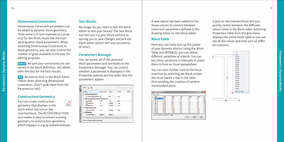
Parameters Manager You can access all of the assorted block parameters and attributes in the Parameters Manager. You can control whether a parameter is displayed in the Properties palette and the order that the parameters appear.
A new option has been added to the Show column to convert between constraint parameters defi ned in the drawing editor vs. the block editor.
Block Table
Here you can really kick up the power of your dynamic blocks! Using the Block Table tool (BTABLE), you can defi ne diff erent variations of a block. You can key these variations in manually or paste them in from an Excel spreadsheet.
You can even further control the block insertion by selecting the Block proper-ties must match a row in the table thus avoiding the creation of random nonstandard parts.
A grip on the inserted block lets you quickly switch between the diff erent values listed in the Block table. Selecting Properties Table from the grip menu displays the entire block table so you can see all the values and even sort on diff er-ent columns.
Powerful Tim
e Savers19
Par
amet
rics
: Dyn
amic
Blo
cks
18
Block Editor SettingsYou can control all the settings for the block editor environment in the Block Editor Settings dialog—including colors, sizes and alignment options.
Mixing the new geometric and dimensional constraints with the traditional parameters and actions can lead to varied results and is not recom-mended.
Powerful Time Savers
There are plenty of great timesaver tools inside of AutoCAD 2011—many wishes have been granted!
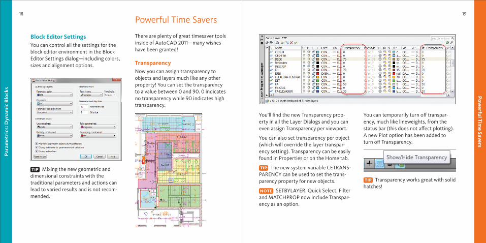
TransparencyNow you can assign transparency to objects and layers much like any other property! You can set the transparency to a value between 0 and 90. 0 indicates no transparency while 90 indicates high transparency.
You’ll fi nd the new Transparency prop-erty in all the Layer Dialogs and you can even assign Transparency per viewport.
You can also set transparency per object (which will override the layer transpar-ency setting). Transparency can be easily found in Properties or on the Home tab.
The new system variable CETRANS-PARENCY can be used to set the trans-parency property for new objects.
SETBYLAYER, Quick Select, Filter and MATCHPROP now include Transpar-ency as an option.
You can temporarily turn off transpar-ency, much like lineweights, from the status bar (this does not aff ect plotting). A new Plot option has been added to turn off Transparency.
Transparency works great with solid hatches!
Powerful Tim
e Savers21
Pow
erfu
l Tim
e Sa
vers
20
PolylinesPolylines have extra grips to make edit-ing much easier. New secondary grips are located at the midpoint of each segment. Hovering over a grip provides several valuable editing options such as stretch, add or remove vertex and Convert to Arc/Line.
Splines
AutoCAD 2011 lets you defi ne a spline using fi t point or control vertices (CV).
When drawing a fi t spline, you can specify start and end tangencies, toler-ance (how close the spline is to the fi t point) and knot parameterization (which controls the shape of the curve as it passes through the fi t point)
You can control the Degree of a CV spline (the number of bends—from 1 to 3—that the spline can take overall).
Use the intuitive grip menu to further control splines.
Use a CV spline if you plan on creat-ing 3D NURBS surfaces for best results.
SPLINEDIT has been updated to include more Edit Vertex options like add kinks or elevate order.
Spline to PLINE The Convert to Polyline option in the SPLINEDIT command lets you quickly make the conversion. You will be prompted for a precision value between 0 and 99 with the higher value being more accurate.
Too high a value could impact performance.
You can also select a spline object in the PEDIT command and convert it to a pline. The new system variable PLINECONVERTMODE controls whether straight segments (0) or arcs (1) are used.
JOIN CommandYou can now join lines, arc and polylines to 3D polylines or splines as long as they are contiguous. Just be sure to select the most complex object fi rst (3D polyline or spline). You can also join a helix to a spline.
Scale ListsYou can now create a Default Scale List (Options command, User Preferences tab) that automatically displays across all of your drawings.
Missing SHX and Font FilesYou can now ignore missing SHX fi les when opening a drawing without specifying a replacement (although text using the missing SHX fi les will not be displayed).
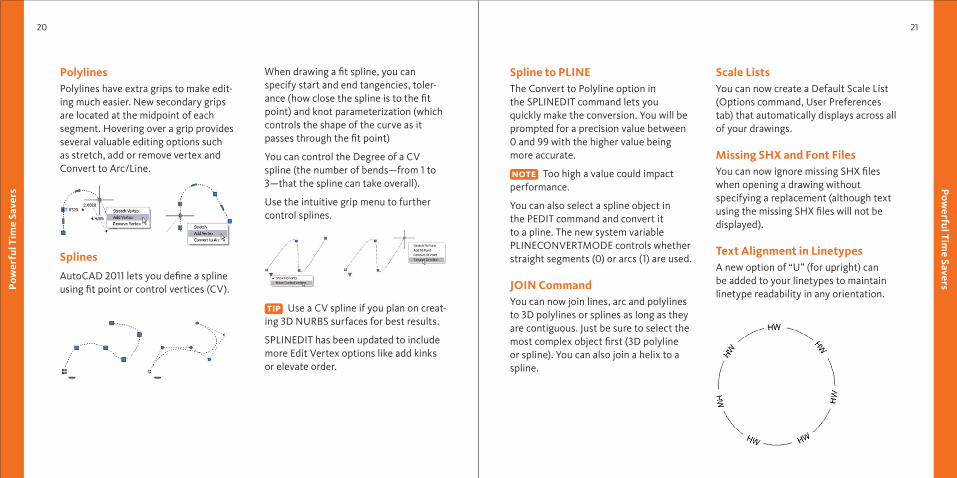
Text Alignment in LinetypesA new option of “U” (for upright) can be added to your linetypes to maintain linetype readability in any orientation.
Improvem
ents to Everyday Com
mands
23
Impr
ovem
ents
to E
very
day
Com
man
ds
22
Select ColorYou can access the Select Color dialog box directly from the Layer drop-down list by selecting a color swatch. If the layer has a viewport color override it now has a white border. It’s also much easier to tell which color you are looking at in the Select Color dialog with the new black border and arrow!
External ReferencesThe External References palette now in-cludes an option to detach data extrac-tion tables from a drawing. You’ll also fi nd that the corresponding reference highlights in the External References palette when selected.
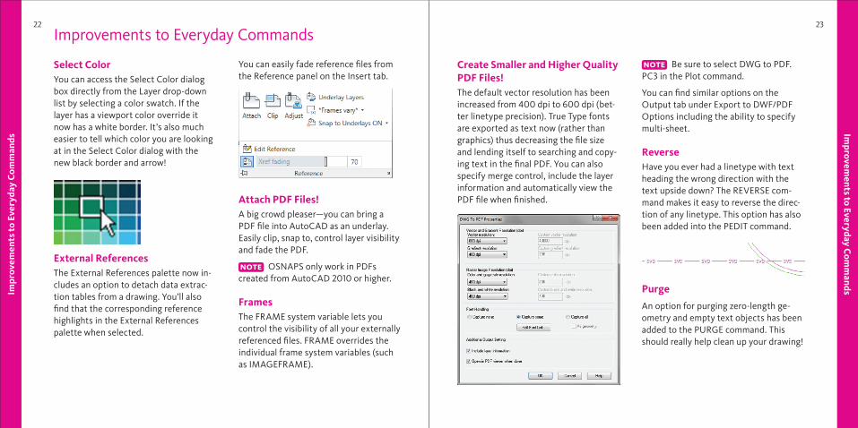
You can easily fade reference fi les from the Reference panel on the Insert tab.
Attach PDF Files!A big crowd pleaser—you can bring a PDF fi le into AutoCAD as an underlay. Easily clip, snap to, control layer visibility and fade the PDF.
OSNAPS only work in PDFs created from AutoCAD 2010 or higher.
FramesThe FRAME system variable lets you control the visibility of all your externally referenced fi les. FRAME overrides the individual frame system variables (such as IMAGEFRAME).
Create Smaller and Higher Quality PDF Files!The default vector resolution has been increased from 400 dpi to 600 dpi (bet-ter linetype precision). True Type fonts are exported as text now (rather than graphics) thus decreasing the fi le size and lending itself to searching and copy-ing text in the fi nal PDF. You can also specify merge control, include the layer information and automatically view the PDF fi le when fi nished.
Be sure to select DWG to PDF.PC3 in the Plot command.
You can fi nd similar options on the Output tab under Export to DWF/PDF Options including the ability to specify multi-sheet.
Reverse Have you ever had a linetype with text heading the wrong direction with the text upside down? The REVERSE com-mand makes it easy to reverse the direc-tion of any linetype. This option has also been added into the PEDIT command.
Purge
An option for purging zero-length ge-ometry and empty text objects has been added to the PURGE command. This should really help clean up your drawing!
Improvements to Everyday Commands
Impr
ovem
ents
to E
very
day
Com
man
ds
24
Measuring Tools
25
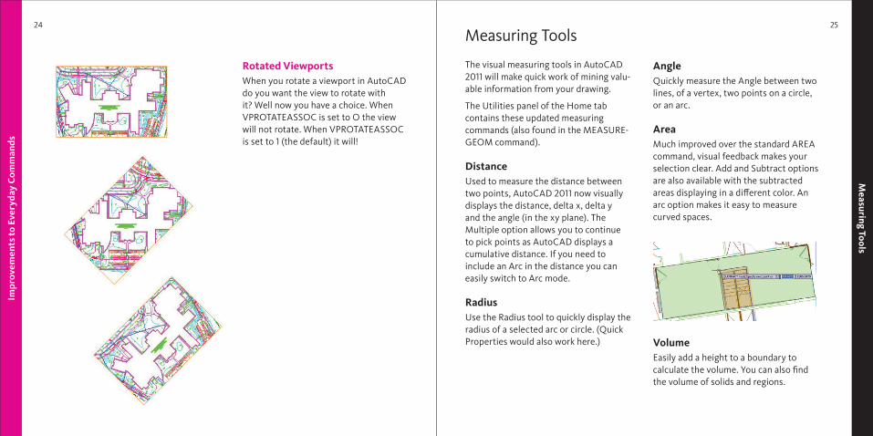
Rotated Viewports When you rotate a viewport in AutoCAD do you want the view to rotate with it? Well now you have a choice. When VPROTATEASSOC is set to O the view will not rotate. When VPROTATEASSOC is set to 1 (the default) it will!
Measuring Tools
The visual measuring tools in AutoCAD 2011 will make quick work of mining valu-able information from your drawing.
The Utilities panel of the Home tab contains these updated measuring commands (also found in the MEASURE-GEOM command).
Distance Used to measure the distance between two points, AutoCAD 2011 now visually displays the distance, delta x, delta y and the angle (in the xy plane). The Multiple option allows you to continue to pick points as AutoCAD displays a cumulative distance. If you need to include an Arc in the distance you can easily switch to Arc mode.
Radius Use the Radius tool to quickly display the radius of a selected arc or circle. (Quick Properties would also work here.)
Angle Quickly measure the Angle between two lines, of a vertex, two points on a circle, or an arc.
Area Much improved over the standard AREA command, visual feedback makes your selection clear. Add and Subtract options are also available with the subtracted areas displaying in a diff erent color. An arc option makes it easy to measure curved spaces.
VolumeEasily add a height to a boundary to calculate the volume. You can also fi nd the volume of solids and regions.
Hat
ches
and
Gra
dien
ts
26
Hatches and G
radients 27
Hatches and Gradients
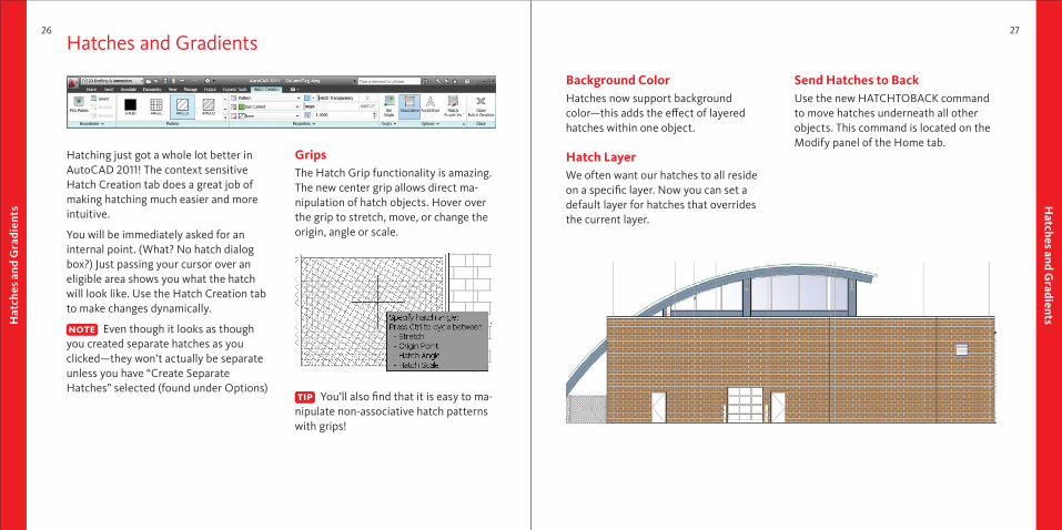
Hatching just got a whole lot better in AutoCAD 2011! The context sensitive Hatch Creation tab does a great job of making hatching much easier and more intuitive.
You will be immediately asked for an internal point. (What? No hatch dialog box?) Just passing your cursor over an eligible area shows you what the hatch will look like. Use the Hatch Creation tab to make changes dynamically.
Even though it looks as though you created separate hatches as you clicked—they won’t actually be separate unless you have “Create Separate Hatches” selected (found under Options)
GripsThe Hatch Grip functionality is amazing. The new center grip allows direct ma-nipulation of hatch objects. Hover over the grip to stretch, move, or change the origin, angle or scale.
You’ll also fi nd that it is easy to ma-nipulate non-associative hatch patterns with grips!
Background ColorHatches now support background color—this adds the eff ect of layered hatches within one object.
Hatch LayerWe often want our hatches to all reside on a specifi c layer. Now you can set a default layer for hatches that overrides the current layer.
Send Hatches to BackUse the new HATCHTOBACK command to move hatches underneath all other objects. This command is located on the Modify panel of the Home tab.
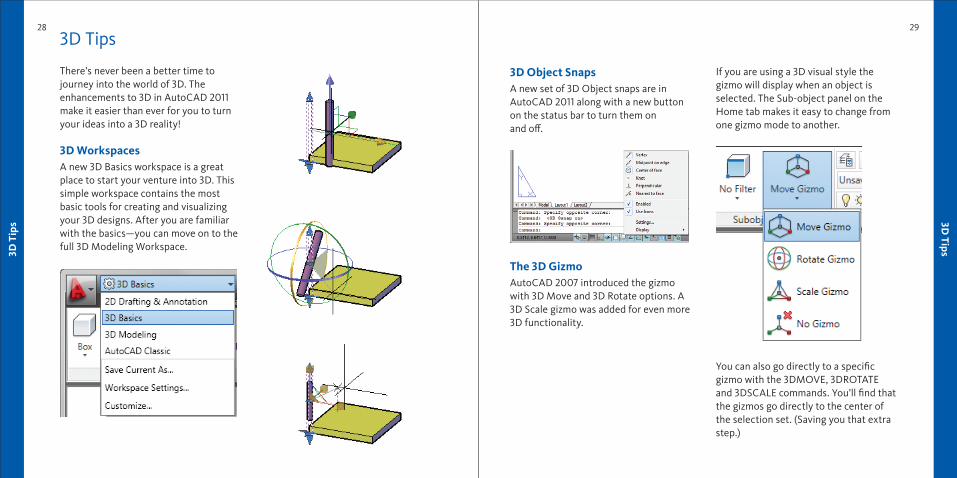
3D Object SnapsA new set of 3D Object snaps are in AutoCAD 2011 along with a new button on the status bar to turn them on and off .
The 3D Gizmo AutoCAD 2007 introduced the gizmo with 3D Move and 3D Rotate options. A 3D Scale gizmo was added for even more 3D functionality.
If you are using a 3D visual style the gizmo will display when an object is selected. The Sub-object panel on the Home tab makes it easy to change from one gizmo mode to another.
You can also go directly to a specifi c gizmo with the 3DMOVE, 3DROTATE and 3DSCALE commands. You’ll fi nd that the gizmos go directly to the center of the selection set. (Saving you that extra step.)
3D T
ips
28
3D Tips
29
3D Tips
There’s never been a better time to journey into the world of 3D. The enhancements to 3D in AutoCAD 2011 make it easier than ever for you to turn your ideas into a 3D reality!
3D WorkspacesA new 3D Basics workspace is a great place to start your venture into 3D. This simple workspace contains the most basic tools for creating and visualizing your 3D designs. After you are familiar with the basics—you can move on to the full 3D Modeling Workspace.
3D T
ips
30
Surface Modeling
31
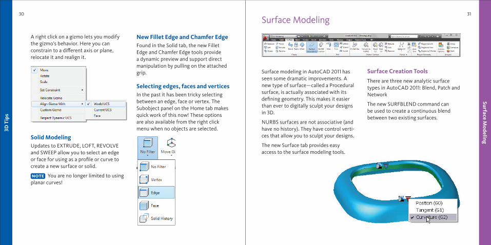
A right click on a gizmo lets you modify the gizmo’s behavior. Here you can constrain to a diff erent axis or plane, relocate it and realign it.
Solid ModelingUpdates to EXTRUDE, LOFT, REVOLVE and SWEEP allow you to select an edge or face for using as a profi le or curve to create a new surface or solid.
You are no longer limited to using planar curves!
New Fillet Edge and Chamfer EdgeFound in the Solid tab, the new Fillet Edge and Chamfer Edge tools provide a dynamic preview and support direct manipulation by pulling on the attached grip.
Selecting edges, faces and vertices In the past it has been tricky selecting between an edge, face or vertex. The Subobject panel on the Home tab makes quick work of this now! These options are also available from the right click menu when no objects are selected.
Surface Modeling
Surface modeling in AutoCAD 2011 has seen some dramatic improvements. A new type of surface—called a Procedural surface, is actually associated with its defi ning geometry. This makes it easier than ever to digitally sculpt your designs in 3D.
NURBS surfaces are not associative (and have no history). They have control verti-ces that allow you to sculpt your designs.
The new Surface tab provides easyaccess to the surface modeling tools.
Surface Creation Tools
There are three new analytic surface types in AutoCAD 2011: Blend, Patch and Network
The new SURFBLEND command can be used to create a continuous blend between two existing surfaces.
32
Surface Modeling
33
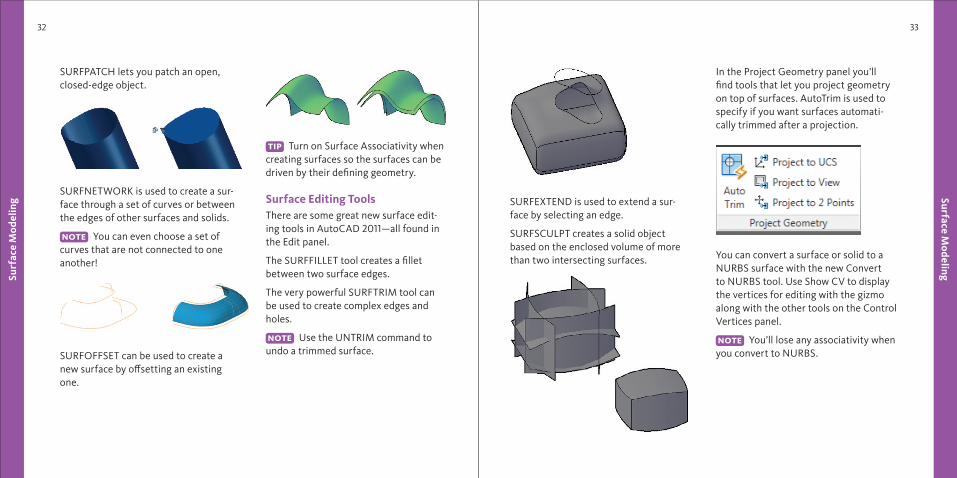
SURFPATCH lets you patch an open, closed-edge object.
SURFNETWORK is used to create a sur-face through a set of curves or between the edges of other surfaces and solids.
You can even choose a set of curves that are not connected to one another!
SURFOFFSET can be used to create a new surface by off setting an existing one.
Turn on Surface Associativity when creating surfaces so the surfaces can be driven by their defi ning geometry.
Surface Editing ToolsThere are some great new surface edit-ing tools in AutoCAD 2011—all found in the Edit panel.
The SURFFILLET tool creates a fi llet between two surface edges.
The very powerful SURFTRIM tool can be used to create complex edges and holes.
Use the UNTRIM command to undo a trimmed surface.
Surf
ace
Mod
elin
g SURFEXTEND is used to extend a sur-face by selecting an edge.
SURFSCULPT creates a solid object based on the enclosed volume of more than two intersecting surfaces.
In the Project Geometry panel you’ll fi nd tools that let you project geometry on top of surfaces. AutoTrim is used to specify if you want surfaces automati-cally trimmed after a projection.
You can convert a surface or solid to a NURBS surface with the new Convert to NURBS tool. Use Show CV to display the vertices for editing with the gizmo along with the other tools on the Control Vertices panel.
You’ll lose any associativity when you convert to NURBS.
34
Mesh M
odeling35
Analysis ToolsA new set of analysis tools have been added into AutoCAD 2011 to help you validate the continuity, curvature and draft angles of surfaces.
Zebra: Maps stripes onto surfaces and meshes for analysis. The more the stripes line up, the higher the continuity between surfaces.
Curvature: Displays a color gradient that indicates high and low areas of curvature along with unacceptable sudden changes such as bumps, dents and ripples.
Draft Angle: Displays a color gradient indicating if there is adequate draft angle between the part and the mold.
3D Printing Use the 3DPrint command to send your 3D AutoCAD drawings to a STL sup-ported 3D printing vendor. A friendly utility will walk you through the steps needed to ensure your model is 3DPrint ready. After selecting the solid objects you want to print you will fi nd yourself in the Send to 3D Print Service dialog. Here you’ll fi nd a preview pane and scale controls (with a helpful fi nished output size). A fi nal OK will send you to a site with possible 3D Printing vendors.
Surf
aceM
odel
ing
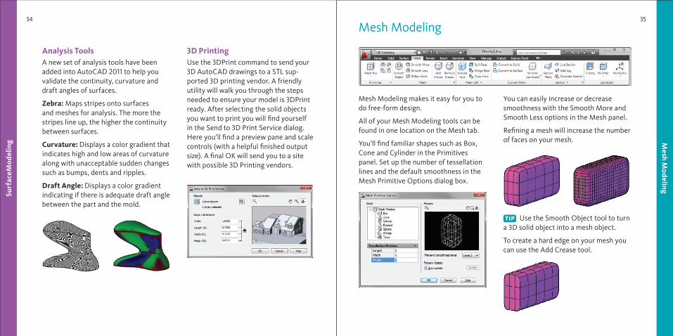
Mesh Modeling
Mesh Modeling makes it easy for you to do free-form design.
All of your Mesh Modeling tools can be found in one location on the Mesh tab.
You’ll fi nd familiar shapes such as Box, Cone and Cylinder in the Primitives panel. Set up the number of tessellation lines and the default smoothness in the Mesh Primitive Options dialog box.
You can easily increase or decrease smoothness with the Smooth More and Smooth Less options in the Mesh panel.
Refi ning a mesh will increase the number of faces on your mesh.
Use the Smooth Object tool to turn a 3D solid object into a mesh object.
To create a hard edge on your mesh you can use the Add Crease tool.
Materials
36 37
Mes
h M
odel
ing
You can split or extrude a face in the Mesh Edit panel.
The biggest bonus? You can convert the watertight meshes (no gaps) to solids. These and more conversion tools are available in the Convert Mesh panel.
Merge Mesh ToolThe new Merge Mesh tool is used to merge two or more adjacent faces into a single face.
The Close Hole tool creates a mesh face between open edges.
Use the Collapse Face or Edge tool to force vertices of surrounding mesh faces to converge.
Use the Spin Triangle Face tool to rotate the edges that join two triangular mesh faces together.
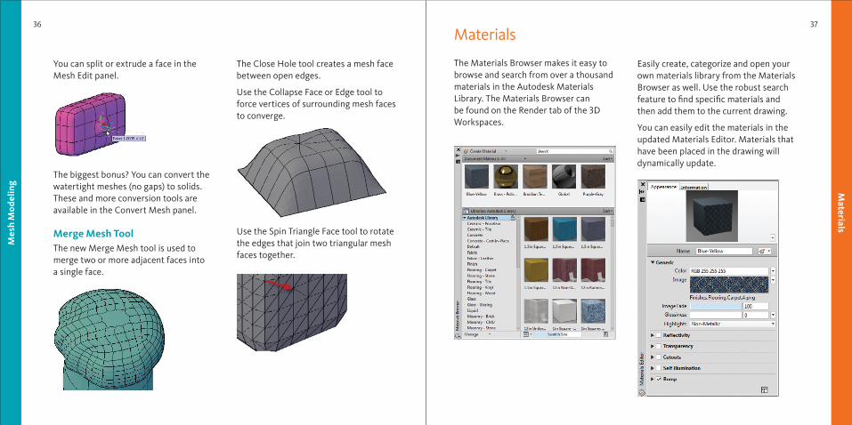
Materials
The Materials Browser makes it easy to browse and search from over a thousand materials in the Autodesk Materials Library. The Materials Browser can be found on the Render tab of the 3D Workspaces.
Easily create, categorize and open your own materials library from the Materials Browser as well. Use the robust search feature to fi nd specifi c materials and then add them to the current drawing.
You can easily edit the materials in the updated Materials Editor. Materials that have been placed in the drawing will dynamically update.
38
Added Extras
39
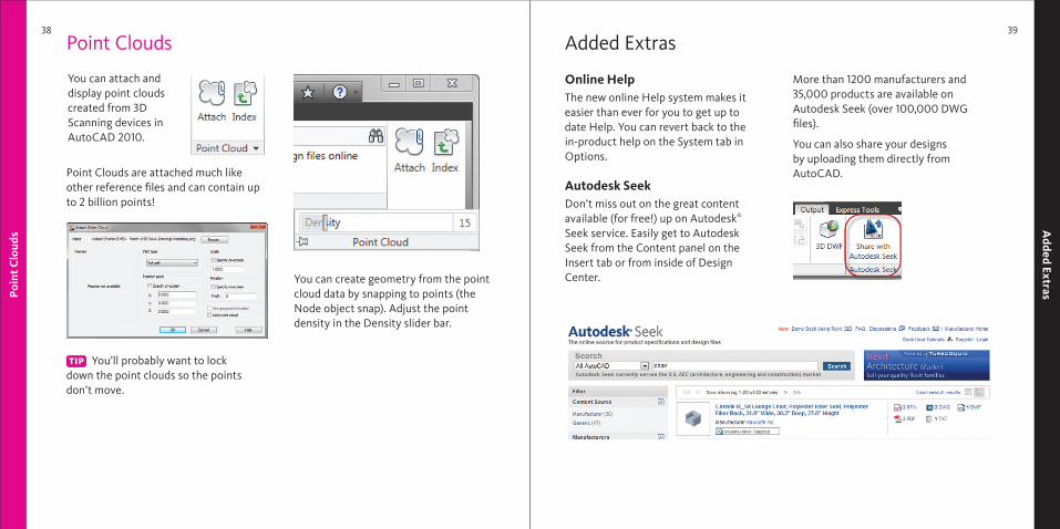
Point Clouds
You can attach and display point clouds created from 3D Scanning devices in AutoCAD 2010.
Point Clouds are attached much like other reference fi les and can contain up to 2 billion points!
You’ll probably want to lock down the point clouds so the points don’t move.
You can create geometry from the point cloud data by snapping to points (the Node object snap). Adjust the point density in the Density slider bar.
Poi
nt C
loud
s
Added Extras
Online HelpThe new online Help system makes it easier than ever for you to get up to date Help. You can revert back to the in-product help on the System tab in Options.
Autodesk SeekDon’t miss out on the great content available (for free!) up on Autodesk® Seek service. Easily get to Autodesk Seek from the Content panel on the Insert tab or from inside of Design Center.
More than 1200 manufacturers and 35,000 products are available on Autodesk Seek (over 100,000 DWG fi les).
You can also share your designsby uploading them directly from AutoCAD.
Lynn Allen, Cadalyst columnist and worldwide Autodesk Technical Evangelist, speaks to more than 30,000 users each year. For the past fi fteen years she has written a monthly column in Cadalyst magazine called “Circles and Lines” and is the voice behind Cadalyst’s “Tips and Tricks Tuesdays”. Lynn started using AutoCAD® software with Release 1.4, over 20 years ago, and got her start by teaching at the corpo-rate and collegiate level for 12 years. A sought-after public speaker with a unique comedic style, Lynn has served as the Autodesk University emcee for ten years and is always one of the highest rated speakers. Her latest book is entitled AutoCAD Professional Tips and Techniques.
Autodesk, AutoCAD, DWF, DWG, SteeringWheels, and ViewCube are reg-istered trademarks or trademarks of Autodesk, Inc., and/or its subsidiaries and/or affi liates in the USA and/or other countries. All other brand names, product names, or trademarks belong to their respective holders. Autodesk reserves the right to alter product off erings and specifi cations at any time without notice, and is not responsible for typographical or graphical errors that may appear in this document.
© 2010 Autodesk, Inc. All rights reserved.