Embed Size (px)
Citation preview

L y c o m i n g F l y e r ��
Lycoming Flyer
O P E R A T I O N S
�� L y c o m i n g F l y e r
Most people seem to operate on the philosophy that they can best get their money’s worth from any mechanical device by treating it with great care. This is probably true, but in many cases, it is necessary to interpret what great care really means. This is par-ticularly applicable when considering the break-in of a modern, reciprocating aircraft engine. Aircraft owners frequently ask about the proper procedures for run-in of a new or rebuilt engine so they can carefully complete the required steps. Many of these recommended break-in procedures also apply to engines which have been overhauled or had a cylinder replaced.
The first careful consideration for engine run-in is the oil to be used. The latest revision of Lycoming Service Instruction 1014 should be consulted for this information. The basic rule which applies to most normally aspirated Lycoming piston engines is simple: use straight mineral oil of the proper viscosity for the first fifty hours or until oil consumption stabilizes. Then switch to ashless dispersant (AD) oil.
The exceptions to the basic rule above are the O-320-H and the O/LO-360-E series. These engines may be operated using either straight mineral oil or ashless dispersant oil; however, if the engine is delivered with ashless dispersant oil installed, it must remain on ashless dispersant oil. The Lycoming oil additive P/N LW-16702 must be added to the O-320-H and O/LO-360-E engines at airframe installation, and every 50 hours thereafter or at every oil change. An FAA-approved lubricating oil that contains, in the proper amount, an oil additive equivalent to LW-16702 will meet the requirements for the additive as stated in Lycoming Service Instruction No. 1014M.
All Lycoming turbocharged engines must be broken in with ash-less dispersant oil only.
When taking delivery of a new aircraft, there is another point which must be emphasized. Some aircraft manufacturers add approved preservative lubricating oil to protect new engines from rust and corrosion at the time the aircraft leaves the factory. This preservative oil must be removed by the end of the first 25 hours of operation.
Each new or rebuilt engine is given a production test run at the factory before the engine is delivered to an aircraft manufacturer or customer. After installation in the aircraft, the engine is run again during the test flights. These test runs will ensure that the engine is operating normally and will provide an opportunity to locate small oil leaks or other minor discrepancies. In addition, these test runs do the initial seating of the piston rings. The rest of the break-in is the responsibility of the pilot who flies the aircraft during the next 50 hours.
A new, rebuilt or overhauled engine should receive the same start, warm-up and preflight checks as any other engine. There are some aircraft owners and pilots who would prefer to use low power settings for cruise during the break-in period. This is not recommended. A good break-in requires that the piston rings expand sufficiently to seat with the cylinder walls. This seating of the ring with the cylinder wall will only occur when pressures
inside the cylinder are great enough to cause expansion of the piston rings. Pressures in the cylinder only become great enough for a good break-in when power settings above 65% are used.
Full power for takeoff and climb during the break-in period is not harmful; it is beneficial, although engine temperatures should be monitored closely to ensure that overheating does not occur. Cruise power settings above 65%, and preferably in the 70% to 75% of rated power range, should be used to achieve a good engine break-in.
Remember that if the new or rebuilt engine is normally aspi-rated (non-turbocharged), it will be necessary to cruise at lower altitudes to obtain the required cruise power levels. Density altitudes in excess of 8000 feet (5000 feet is recommended) will not allow the engine to develop sufficient cruise power for a good break-in.
For those who still think that running the engine hard during break-in falls into the category of cruel and unusual punishment, there is one more argument for high power settings during engine break-in. The use of low power settings does not expand the piston rings enough, and a film of oil is left on the cylinder walls. The high temperatures in the combustion chamber will oxidize this oil film so that it creates a condition commonly known as glazing of the cylinder walls. When this happens, the ring break-in process stops, and excessive oil consumption frequently occurs. The bad news is that extensive glazing can only be corrected by removing the cylinders and rehoning the walls. This is expensive, and it is an expense that can be avoided by proper break-in procedures.
To summarize, there are just a few items to remember about engine break-in:
1. If a preservative oil has been added by the aircraft manufac-turer, drain it no later than the first 25 hours of operation;
2. Follow the engine manufacturer’s recommendation regarding the oil to be used for break-in and the period between changes;
3. Run the engine at high cruise power levels for best piston ring/cylinder wall mating;
4. Continue break-in operation for 50 hours or until oil consump-tion stabilizes. These simple procedures should eliminate the possibility of cylinder wall glazing and should prepare the engine for a long and satisfactory service life.
A direct reprint of Service Instruction 1094D
Revision “D” to Service Instruction No. 1094 supersedes all previous recommendations and should be used for engine leaning during normal flight operations. All leaning recommen-dations are based on calibrated instrumentation.
Lycoming strongly recommends that all engine instrumentation be calibrated annually. All instrumentation for manifold pressure, engine RPM, oil temperature, cylinder head temperature, exhaust
L y c o m i n g F l y e r ��
gas temperature and turbine inlet temperature in the aircraft should be included in this annual calibration.
Regardless of the fuel metering device, fuel management of normally aspirated engines is primarily dependant on the instru-mentation available. The method is the same for both fixed- and controllable- pitch propellers.
Lycoming recommendations for leaning turbocharged engines in this Service Instruction refer to Lycoming-supplied turbocharged engines. For aftermarket turbocharger installations, contact the STC holder for proper leaning instructions.
CHT (cylinder head temperature) and TIT (turbine inlet tempera-ture) probes are required for leaning turbocharged engines. Refer to the latest edition of Service Instruction No. 1422 for proper TIT probe locations and depth.
A. GENERAL RULES
1. Without exception, observe the red-line temperature limits during takeoff, climb and high-performance cruise power operation.
a. Cylinder head temperature — maximum limit listed in the Lycoming Operator’s Manual.
b. Oil temperature limit — maximum limit listed in the Lycoming Operator’s Manual.
c. TIT - maximum allowable limit specified in the Lycoming Operator’s Manual.
2. Whenever mixture is adjusted, rich or lean, it should be done slowly.
3. Always return mixture slowly to full before increasing power setting.4. At all times, caution must be taken not to shock-cool the cylinders. The maximum recommended temperature change should not exceed 50˚ F per minute.
B. LEANING THE NORMALLY ASPIRATED ENGINES
1. Use full-rich mixture during takeoff or climb. Careful obser-vation of engine temperature instruments should be practiced to ensure the limits specified in Lycoming Operator’s Manual are never exceeded. Refer to the aircraft POH (Pilot’s Operating Handbook) or AFM (Aircraft Flight Manual) for more specific instructions.
2. For 5,000 feet density altitude and above, or high ambient temperatures, roughness or reduction of power may occur at full rich mixture. The mixture may be adjusted to obtain smooth engine operation. For fixed-pitch propellers, lean to maximum RPM at full throttle prior to takeoff where airports are at 5,000-feet density altitude or higher. Limit operation at full throttle on the ground to a minimum. For direct-drive and for normally aspirated engines with a prop governor, but without fuel flow or EGT, set throttle at full power and lean mixture at maximum RPM with smooth operation of the engine as a deciding factor.
3. For cruise powers where best power mixture is allowed, slowly lean the mixture from full rich to maximum power. Best power mixture operation provides the most miles per hour for a given power setting. For engines equipped with fixed-pitch
propellers, gradually lean the mixture until either the tachometer or the airspeed indicator reading peaks. For engines equipped with controllable pitch propellers, lean until a slight increase of airspeed is noted.
4. For a given power setting, best economy mixture provides the most miles per gallon. Slowly lean the mixture until engine opera-tion becomes rough or until engine power rapidly diminishes as noted by an undesirable decrease in airspeed. When either condi-tion occurs, enrich the mixture sufficiently to obtain an evenly firing engine or to regain most of the lost airspeed or engine RPM. Some engine power and airspeed must be sacrificed to gain a best economy mixture setting.
NOTE — When leaned, engine roughness is caused by mis-firing due to a lean fuel/air mixture which will not support combustion. Roughness is eliminated by enriching slightly until the engine is smooth.
5. The exhaust gas temperature (EGT) offers little improvement in leaning the float-type carburetor over the procedures outlined above because of imperfect mixture distribution. However, if the EGT probe is installed, lean the mixture to 100˚ F on the rich side of peak EGT for best power operation. For best economy cruise, operate at peak EGT. If roughness is encountered, enrich the mixture slightly for smooth engine operation.
6. When installing an EGT probe, the probe must be installed in the leanest cylinder. Contact the airframe or kit manufacturer for the correct location. In experimental or custom applications, multiple probe instrumentation is required, and several power settings should be checked in order to determine the leanest cylinder for the specific application.
7. During normal operation, maintain the following recommended temperature limits:
a. Cylinder head temperature — limit listed in the Lycoming Operator’s Manual.
b. Oil temperature — limit listed in the Lycoming Operator’s Manual.
8. For maximum service life, maintain the following rec-ommended limits for continuous cruise operation:
a. Engine power setting — 65% of rated or less.
b. Cylinder head temperatures — 400˚ F. or below.
c. Oil temperature — 165˚ F. — 220˚ F.
C. LEANING THE TURBOCHARGED LYCOMING POWER PLANT
1. The cylinder head temperature (CHT) and turbine inlet tem-perature (TIT) gages are required instruments for leaning with turbocharging by Lycoming. EGT probes on individual cylinders should not be used for leaning.
2. During manual leaning, the maximum allowable TIT for a particular engine must not be exceeded. Check the POH/AFM or the Lycoming Operator’s Manual to determine these temperatures and fuel-flow limits.
�8 L y c o m i n g F l y e r
3. Maintaining engine temperature limits may require adjust-ments to fuel flow, cowl flaps or airspeed for cooling.
4. All normal takeoffs, with turbocharged power plants, must be at full-rich mixture regardless of airport elevation.
5. If manual leaning of the mixture is permitted at takeoff, climb power or high-performance cruise, it will be specified in the POH/AFM and will list required ranges for fuel flow, power set-tings and temperature limitations.
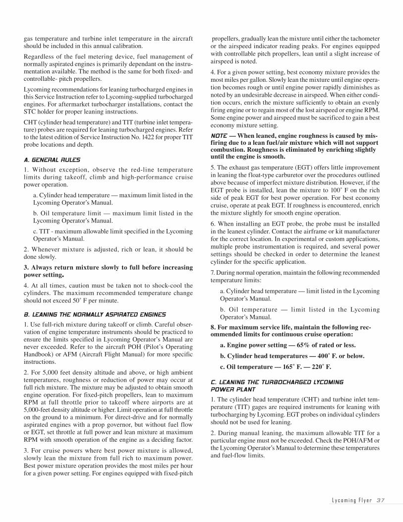
6. Leaning to best economy mixture.
a. Set manifold pressure and RPM for the desired cruise power setting per the aircraft POH/AFM.
b. Lean slowly in small steps, while monitoring instrumen-tation, to peak TIT or maximum allowable TIT, whichever occurs first.
7. Leaning to best power mixture.
Before leaning to best power mixture, it is necessary to establish a TIT reference point. This is accomplished as follows:
a. Set manifold pressure and RPM for the highest cruise power setting where leaning to best economy is permitted per the aircraft POH/AFM.
b. Lean slowly in small steps until peak TIT or max-imum allowable TIT is reached. Record peak TIT as a reference point.
c. Deduct 125˚ F. from this reference, and thus establish the TIT temperature for best power-mixture operation.
d. Return the mixture to full-rich, and adjust manifold pres-sure and RPM for the desired cruise conditions.
e. Lean mixture to the TIT temperature for best power/mixture operation established in step c.
8. During normal operation, maintain the following limits:
a. Engine power setting — rating listed in the Lycoming Operator’s Manual.
b. Cylinder head temperature — limit listed in the Lycoming Operator’s Manual.
c. Oil temperature — limit listed in the Lycoming Operator’s Manual.
d. Turbine inlet temperature — limit listed in the Lycoming Operator’s Manual.
9. For maximum service life, maintain the following recom-mended limits for continuous operation.
a. Engine power setting — 65% of rated or less.
b. Cylinder head temperatures — 400˚ F. or below.
c. Oil temperature — 165˚ F. — 220˚ F.
d. Turbine inlet temperature — maintain 100˚ F. on rich side of maximum allowable.
D. LEANING THE SUPERCHARGED LYCOMING POWER PLANTS
1. All takeoffs with supercharged power plants must be at full-rich mixture regardless of the airport elevation.
2. If manual leaning of the mixture is permitted at climb power, it will be specified in the POH/AFM and will list required ranges for fuel flow, power settings and temperature limitations.
3. Recommended standard cruise power for the supercharged engine is 65%. At 65% power or less, this type of engine may be leaned as desired as long as the engine operates smoothly, and temperatures and pressures are within manufacturer’s prescribed limits.
4. The exhaust gas temperature (EGT) gage is a helpful instru-ment for leaning the supercharged engine at cruise power with a manual mixture control.
L y c o m i n g F l y e r �9
This Article Now Incorporates Material From “A Special On Fuel Management” Which Has Been Eliminated
Various Lycoming Flyer articles have emphasized proper leaning at the manufacturer’s recommended cruise power. Before delving into the savings to be obtained by leaning, it may be appropriate to again review those factors that affect leaning at cruise.
First, we must know that cruise power for Lycoming normally aspirated engines is generally considered to be 55% to 75% of the maximum power for which the engine is rated. At these power set-tings, the engine may be leaned at any altitude. There has been confusion about the reference to not leaning below 5000-feet den-sity altitude. Remember that this reference only applies to those power settings above the cruise range — those normally used for takeoff and climb. Once cruise power has been set, leaning to best economy should be standard procedure as damage to the engine will not occur from leaning at cruise power settings.
In this article, we will expand our discussion of leaning and explain (1) how it saves dollars, and (2) how it aids safe flight. In a practical approach to our subject, let’s look closely at the chart printed below:
Leaning the normally aspirated, direct-drive Lycoming engine at cruise vs. full rich at 4,000-feet density altitude, 75% power.
Engine Model Airplane Model
300 HP Piper Cherokee 300
Full Best Economy Hours Hours
Rich (Peak EGT) Rich Lean
19+ gals. 15.6 gals. 4.2 hrs. 5.1 hrs.
Engine Model Airplane Model
250 HP Piper Aztec
Full Best Economy Hours Hours
Rich (Peak EGT) Rich Lean
16.2 gals. 13.6 gals. 4.3 hrs. 5.1 hrs.
Engine Model Airplane Model
180 HP Cessna Cardinal
Full Best Economy Hours Hours
Rich (Peak EGT) Rich Lean
11.9 gals .9.7 gals. 4.1 hrs. 5.1 hrs.
To put the cost of operating at a full-rich mixture setting during cruise flight into perspective, let us assume that the cost of avia-tion gasoline is $4.00 per gallon. In each case, it is only neces-sary to multiply the difference in gallons burned at “Full Rich” vs. “Best Economy” times the fuel price. The number obtained will be the amount saved each hour of flight by operating at best economy during cruise. Using the examples above, these are the savings for each of those aircraft and engines:
Aircraft Fuel-burn difference Fuel-cost savings
Cherokee 300 3.4 gallons X $4.00 = $13.60 per hr.
Aztec 5.2 gallons X $4.00 = $20.80 per hr.
Cardinal 2.2 gallons X $4.00 = $8.80 per hr.
While we are on a discussion of unnecessary costs of operation, another important factor is the damage often done to engine accessories by operating at full rich at cruise power. Engines operating at full rich in cruise tend to be rough, resulting in shaking engine accessories and engine mounts, thereby consid-erably reducing their life and often resulting in expensive early replacement. A properly leaned engine at cruise power is a smooth engine — and will save money.
In earlier issues of the Flyer, we have been telling all concerned about the benefits to the spark plug of proper leaning at cruise power. That information can be repeated in this discussion, because it helps to illustrate our point on saving dollars. Proper leaning at cruise helps prevent spark plug fouling. The mainte-nance cost to remove and clean spark plugs can be reduced by good leaning techniques. Frequent cleaning of spark plugs reduces their life and requires early replacement. Furthermore, badly fouled spark plugs could also become a safety-of-flight problem.
For a very interesting safety-of-flight item, let’s look at the chart again. Notice the difference in hours of flight at full rich vs. lean at cruise. In the illustration of the 180 HP engine, there is one full additional hour of flight when properly leaned. The other engines provide nearly an additional hour of flight time when leaned to best economy during cruise. Efficient fuel management is a very real safety-of -flight fact.
These are some of the more important facts that illustrate how proper leaning at cruise power aids safe flight — and saves dollars.
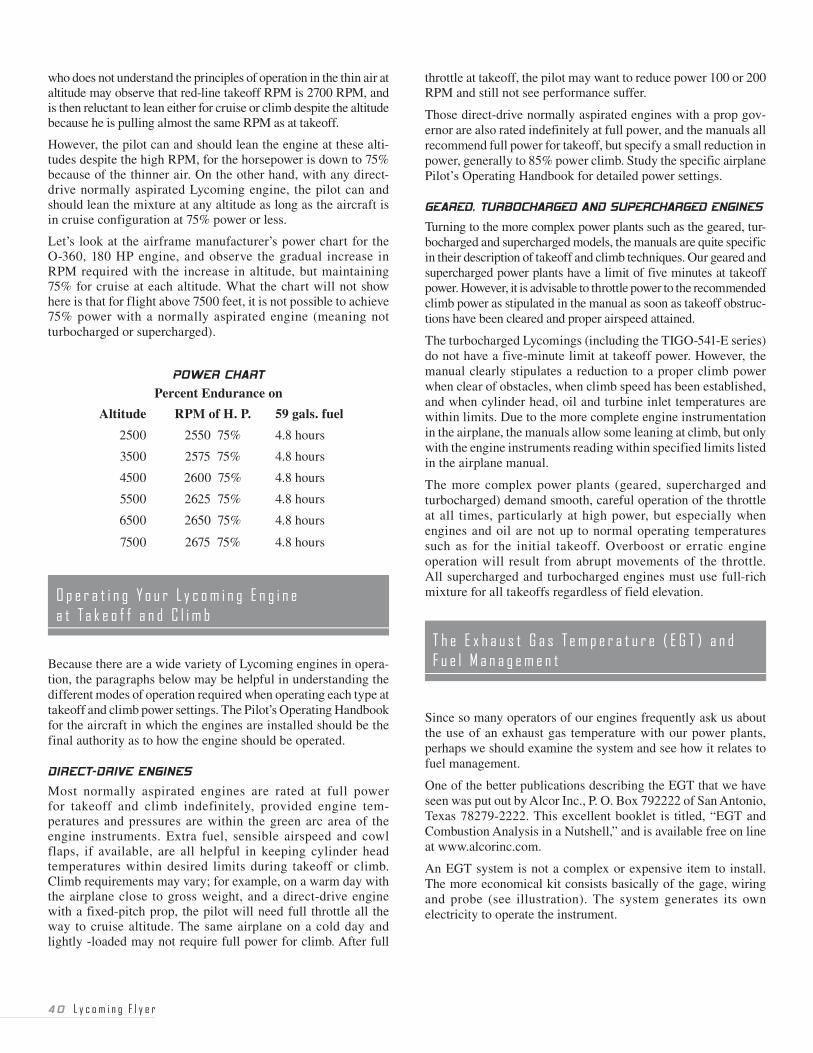
Some pilots have demonstrated a lack of understanding with regard to the operation of the direct-drive, fixed-pitch, normally aspirated power plants. When a power chart is provided, it will indicate that as the airplane is flown at different altitudes above sea level, it is neces-sary to use a higher RPM for adequate cruise performance with an increase in altitude. A typical example might be the O-360, 180 HP Lycoming power plant. The power chart by the airframe manufac-turer for this fixed-landing gear aircraft lists 75% power at 7,500 feet at 2675 RPM (no manifold pressure gage in their airplane). The pilot
�0 L y c o m i n g F l y e r
who does not understand the principles of operation in the thin air at altitude may observe that red-line takeoff RPM is 2700 RPM, and is then reluctant to lean either for cruise or climb despite the altitude because he is pulling almost the same RPM as at takeoff.
However, the pilot can and should lean the engine at these alti-tudes despite the high RPM, for the horsepower is down to 75% because of the thinner air. On the other hand, with any direct-drive normally aspirated Lycoming engine, the pilot can and should lean the mixture at any altitude as long as the aircraft is in cruise configuration at 75% power or less.
Let’s look at the airframe manufacturer’s power chart for the O-360, 180 HP engine, and observe the gradual increase in RPM required with the increase in altitude, but maintaining 75% for cruise at each altitude. What the chart will not show here is that for flight above 7500 feet, it is not possible to achieve 75% power with a normally aspirated engine (meaning not turbocharged or supercharged).
POWER CHART
Percent Endurance on
Altitude RPM of H. P. 59 gals. fuel
2500 2550 75% 4.8 hours
3500 2575 75% 4.8 hours
4500 2600 75% 4.8 hours
5500 2625 75% 4.8 hours
6500 2650 75% 4.8 hours
7500 2675 75% 4.8 hours
Because there are a wide variety of Lycoming engines in opera-tion, the paragraphs below may be helpful in understanding the different modes of operation required when operating each type at takeoff and climb power settings. The Pilot’s Operating Handbook for the aircraft in which the engines are installed should be the final authority as to how the engine should be operated.
DIRECT-DRIVE ENGINES
Most normally aspirated engines are rated at full power for takeoff and climb indefinitely, provided engine tem-peratures and pressures are within the green arc area of the engine instruments. Extra fuel, sensible airspeed and cowl flaps, if available, are all helpful in keeping cylinder head temperatures within desired limits during takeoff or climb. Climb requirements may vary; for example, on a warm day with the airplane close to gross weight, and a direct-drive engine with a fixed-pitch prop, the pilot will need full throttle all the way to cruise altitude. The same airplane on a cold day and lightly -loaded may not require full power for climb. After full
throttle at takeoff, the pilot may want to reduce power 100 or 200 RPM and still not see performance suffer.
Those direct-drive normally aspirated engines with a prop gov-ernor are also rated indefinitely at full power, and the manuals all recommend full power for takeoff, but specify a small reduction in power, generally to 85% power climb. Study the specific airplane Pilot’s Operating Handbook for detailed power settings.
GEARED, TURBOCHARGED AND SUPERCHARGED ENGINES
Turning to the more complex power plants such as the geared, tur-bocharged and supercharged models, the manuals are quite specific in their description of takeoff and climb techniques. Our geared and supercharged power plants have a limit of five minutes at takeoff power. However, it is advisable to throttle power to the recommended climb power as stipulated in the manual as soon as takeoff obstruc-tions have been cleared and proper airspeed attained.
The turbocharged Lycomings (including the TIGO-541-E series) do not have a five-minute limit at takeoff power. However, the manual clearly stipulates a reduction to a proper climb power when clear of obstacles, when climb speed has been established, and when cylinder head, oil and turbine inlet temperatures are within limits. Due to the more complete engine instrumentation in the airplane, the manuals allow some leaning at climb, but only with the engine instruments reading within specified limits listed in the airplane manual.
The more complex power plants (geared, supercharged and turbocharged) demand smooth, careful operation of the throttle at all times, particularly at high power, but especially when engines and oil are not up to normal operating temperatures such as for the initial takeoff. Overboost or erratic engine operation will result from abrupt movements of the throttle. All supercharged and turbocharged engines must use full-rich mixture for all takeoffs regardless of field elevation.
Since so many operators of our engines frequently ask us about the use of an exhaust gas temperature with our power plants, perhaps we should examine the system and see how it relates to fuel management.
One of the better publications describing the EGT that we have seen was put out by Alcor Inc., P. O. Box 792222 of San Antonio, Texas 78279-2222. This excellent booklet is titled, “EGT and Combustion Analysis in a Nutshell,” and is available free on line at www.alcorinc.com.
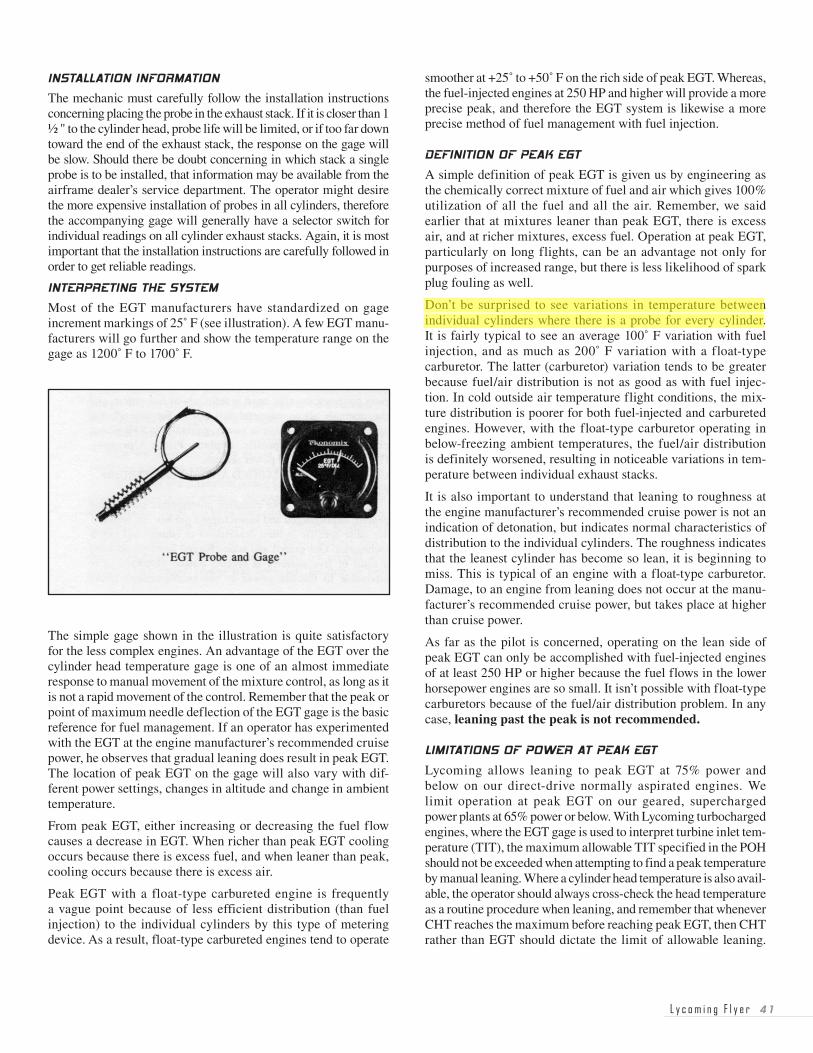
An EGT system is not a complex or expensive item to install. The more economical kit consists basically of the gage, wiring and probe (see illustration). The system generates its own electricity to operate the instrument.
L y c o m i n g F l y e r � �
INSTALLATION INFORMATION
The mechanic must carefully follow the installation instructions concerning placing the probe in the exhaust stack. If it is closer than 1 ½ " to the cylinder head, probe life will be limited, or if too far down toward the end of the exhaust stack, the response on the gage will be slow. Should there be doubt concerning in which stack a single probe is to be installed, that information may be available from the airframe dealer’s service department. The operator might desire the more expensive installation of probes in all cylinders, therefore the accompanying gage will generally have a selector switch for individual readings on all cylinder exhaust stacks. Again, it is most important that the installation instructions are carefully followed in order to get reliable readings.
INTERPRETING THE SYSTEM
Most of the EGT manufacturers have standardized on gage increment markings of 25˚ F (see illustration). A few EGT manu-facturers will go further and show the temperature range on the gage as 1200˚ F to 1700˚ F.
The simple gage shown in the illustration is quite satisfactory for the less complex engines. An advantage of the EGT over the cylinder head temperature gage is one of an almost immediate response to manual movement of the mixture control, as long as it is not a rapid movement of the control. Remember that the peak or point of maximum needle deflection of the EGT gage is the basic reference for fuel management. If an operator has experimented with the EGT at the engine manufacturer’s recommended cruise power, he observes that gradual leaning does result in peak EGT. The location of peak EGT on the gage will also vary with dif-ferent power settings, changes in altitude and change in ambient temperature.
From peak EGT, either increasing or decreasing the fuel flow causes a decrease in EGT. When richer than peak EGT cooling occurs because there is excess fuel, and when leaner than peak, cooling occurs because there is excess air.
Peak EGT with a float-type carbureted engine is frequently a vague point because of less efficient distribution (than fuel injection) to the individual cylinders by this type of metering device. As a result, float-type carbureted engines tend to operate
smoother at +25˚ to +50˚ F on the rich side of peak EGT. Whereas, the fuel-injected engines at 250 HP and higher will provide a more precise peak, and therefore the EGT system is likewise a more precise method of fuel management with fuel injection.
DEFINITION OF PEAK EGT
A simple definition of peak EGT is given us by engineering as the chemically correct mixture of fuel and air which gives 100% utilization of all the fuel and all the air. Remember, we said earlier that at mixtures leaner than peak EGT, there is excess air, and at richer mixtures, excess fuel. Operation at peak EGT, particularly on long flights, can be an advantage not only for purposes of increased range, but there is less likelihood of spark plug fouling as well.
Don’t be surprised to see variations in temperature between individual cylinders where there is a probe for every cylinder. It is fairly typical to see an average 100˚ F variation with fuel injection, and as much as 200˚ F variation with a float-type carburetor. The latter (carburetor) variation tends to be greater because fuel/air distribution is not as good as with fuel injec-tion. In cold outside air temperature flight conditions, the mix-ture distribution is poorer for both fuel-injected and carbureted engines. However, with the float-type carburetor operating in below-freezing ambient temperatures, the fuel/air distribution is definitely worsened, resulting in noticeable variations in tem-perature between individual exhaust stacks.
It is also important to understand that leaning to roughness at the engine manufacturer’s recommended cruise power is not an indication of detonation, but indicates normal characteristics of distribution to the individual cylinders. The roughness indicates that the leanest cylinder has become so lean, it is beginning to miss. This is typical of an engine with a float-type carburetor. Damage, to an engine from leaning does not occur at the manu-facturer’s recommended cruise power, but takes place at higher than cruise power.
As far as the pilot is concerned, operating on the lean side of peak EGT can only be accomplished with fuel-injected engines of at least 250 HP or higher because the fuel flows in the lower horsepower engines are so small. It isn’t possible with float-type carburetors because of the fuel/air distribution problem. In any case, leaning past the peak is not recommended.
LIMITATIONS OF POWER AT PEAK EGT
Lycoming allows leaning to peak EGT at 75% power and below on our direct-drive normally aspirated engines. We limit operation at peak EGT on our geared, supercharged power plants at 65% power or below. With Lycoming turbocharged engines, where the EGT gage is used to interpret turbine inlet tem-perature (TIT), the maximum allowable TIT specified in the POH should not be exceeded when attempting to find a peak temperature by manual leaning. Where a cylinder head temperature is also avail-able, the operator should always cross-check the head temperature as a routine procedure when leaning, and remember that whenever CHT reaches the maximum before reaching peak EGT, then CHT rather than EGT should dictate the limit of allowable leaning.
�� L y c o m i n g F l y e r
BEST ECONOMY MIXTURE
Best economy mixture as it relates to the EGT system begins at peak. For all practical purposes with Lycoming engines, peak EGT is right at the edge of best economy mixture, and is our only practical point of reference in the best economy mixture range. At the manufacturer’s recommended cruise power, peak EGT causes a slight loss of horsepower usually reflected in two or three miles per hour of airspeed. If the pilot attempts to go leaner than peak EGT (with fuel injection only), the power decreases rapidly as fuel flow decreases.
BEST POWER MIXTURE
Best power mixture, or sometimes termed maximum power range, as depicted on the EGT gage, is in the range of plus 100˚ F on the rich side of peak. Best power mixture will provide fastest indicated airspeed for a cruise power setting, although it is generally not considered a practical economic mixture for cruise purposes. However, best power mixture generally provides a safe amount of fuel for a power setting higher than the engine manufacturer’s recommended cruise, except that needed for takeoff power.
Again, we repeat that maximum leaning (peak EGT) does not damage an engine at the engine manufacturer’s recom-mended cruise power. Damage is caused by maximum leaning at higher than recommended cruise power where the manuals do not spell it out or allow it, and when the aircraft does not have a complete set of reliable engine instruments to protect the power plants. Excessive leaning under the latter high power conditions can cause detonation and/or preignition and possible engine failure.
If we were to sum up the major advantages of an EGT to the operator, they are as follows:
1. Saves fuel — an economy aid.
2. Aids proper mixture control — more precise fuel management.
3. Helps increase range.
4. Detects some types of engine troubles.
5. Aids peak engine performance at cruise.
6. Helps prevent spark plug fouling.
7. Fits any General Aviation piston aircraft engine.
Although use of the EGT has the advantages listed above, from a pilot’s point of view, there are also some possible disadvantages. Poor mixture distribution to the cylinders (particularly in car-bureted engines) is the primary reason for these disadvantages. The EGT probe is to be installed in the leanest cylinder, but this changes with altitude and power setting, therefore making it very difficult, or perhaps impossible, to choose a best cylinder for probe installation. Without an EGT installation, the pilot can easily lean using the leanest cylinder of a carbureted engine by simply leaning to find engine roughness from the first indica-tion of “lean misfire,” and then richening the mixture to smooth engine operation.
The pilot must also realize that even with a fuel-injected engine, there will be variations in fuel flow. Utilizing an EGT with probes in each exhaust stack (sometimes called a combustion analyzer) will show these variations. Trying to interpret the variations in temperature shown for each cylinder has caused some pilots to suspect problems with their engine when it has been operating normally. Sometimes too much knowledge can be a problem.
Finally, the EGT system must be in perfect working order to give accurate readings. The probes in the exhaust system will deteriorate with age and continuous use. This often causes the gage to read a temperature that is not accurate, and therefore a peak reading that is not reached soon enough. This results in overleaning to the lean side of peak where operation is not recom-mended. Frequent maintenance to ensure that temperature probes are in good condition will reduce the possibility of inaccuracies, but the pilot cannot determine the accuracy of this rather critical reading during operation.
The exhaust gas temperature system, when well maintained and thoroughly understood, can be an aid in proper leaning at cruise power with fuel-injected power plants. It is hoped that this infor-mation will help the operators of Lycoming engines achieve the best possible engine efficiency through use of the EGT system.
Pilots frequently ask us for information and guidance concerning landings and takeoffs from high-elevation airports. Our reference point in this discussion will be based on density altitude. The discussion also requires that we treat separately operation of normally aspirated, turbocharged and supercharged engines at high-elevation airports.
NORMALLY ASPIRATED
The normally aspirated engine performs and reacts to density altitude. As an example, this type of power plant at takeoff from an airport with an indicated altitude of 3,000 feet, but with an ambient temperature at 85˚ F, would have a density altitude of more than 5,000 feet. The engine would lack some 20 to 25% of its power and also probably run rough because of a rich mixture on the ground at full rich. Therefore, the typical normally aspirated direct-drive engine requires the mixture be leaned on the ground for efficient takeoff performance where airports are 5,000 feet (density altitude) or higher. The over-rich condition is something the pilot can compensate for by leaning. However, the higher-density altitude with its thinner air cannot be compensated for with a normally aspirated engine unless a supercharger or turbocharger unit is added to the power plant. Thus, at density altitudes of 5,000 - 6,000 feet, the pilot of a nor-mally aspirated engine has available to him approximately 75% of the engine power, and must plan his takeoff accordingly after setting the mixture.
L y c o m i n g F l y e r ��
PROCEDURE FOR LEANING
1. The fixed-pitch propeller — lean to maximum RPM at full throttle prior to takeoff where airports are 5,000 feet density altitude or higher. Limit operation at full throttle on the ground to a minimum time.
2. The direct-drive normally aspirated engine with a prop gov-ernor but without a fuel-flow gage, set throttle at full power and lean mixture at maximum RPM with smooth operation of the engine as a deciding factor.
3. With fuel injection, if the power plant has a marked fuel-flow gage, then set mixture in accordance with instructions on the fuel-flow gage and/or in accordance with the airplane Pilot’s Operating Handbook.
4. Pressure carburetor — All Lycoming engines equipped with Bendix PS carburetors have an automatic mixture control which does not require leaning for takeoff.
5. Turbocharged and supercharged engines — All takeoffs must be at full-rich mixture, because the engine is brought back to sea level horsepower which does not permit leaning.
DESCENT
Regardless of the field elevation where the pilot intends to land, the descent from cruise altitude to traffic pattern altitude should be made with the engine leaned for smooth engine operation. Low elevation fields (below 5,000 feet density altitude) will require that the mixture be moved to full rich in the “before landing checklist.” Landing at airports above 5,000 feet density altitude, the mixture must be leaned to smooth engine operation during traffic pattern flight and landing; otherwise, the engine may stop on the runway because of excessive richness.
TO INCREASE POWER — first, enrich mixture, increase RPM, then follow with throttle.
TO DECREASE POWER — first, reduce throttle, reduce RPM, and then adjust mixture.
INCREASING POWER — enrich mixture first to ensure pro-tecting the engine against damage from higher power when previously leaned out for a lower power setting.
Next, increase RPM because in some models the engine and propeller would have undesirable pressure and stresses with a high manifold pressure and lower RPM.
Then, follow with the appropriate manifold pressure, now that the mixture and RPM have been correctly set to accommodate the increased throttle.
DECREASING POWER — Most models of our engines require the basic procedure for decrease of power by retarding throttle, followed by RPM. However, we do have an excep-
tion in several older models of our geared normally aspirated power plants, such as the GO-480 and GO-435 series. In the climb configuration, we recommended full throttle throughout the climb for internal fuel cooling with RPM reductions ini-tially to 3000 RPM and then 2750 RPM for prolonged climb. Turbocharged and supercharged engines require careful applica-tion of the basic power sequences as outlined in the beginning. It is also possible to create an overboost condition on these engines by going to takeoff manifold pressure at cruise RPM, such as might take place in an unexpected go-around. The stresses and pressures on prop and engine would create a threat to both.
A letter received here at the factory asked a question we have heard quite often:
“Is it a fact, or is it fiction, that engines with constant speed props should not use power settings where inches of mer-cury exceed RPM in hundreds? I am referring, of course, to non-turbocharged engines in general .”
The answer to this question is easily found in cruise power charts of the airframe Pilot’s Operating Handbook. Whatever the combinations of RPM and MP listed in the charts — they have been flight tested and approved by the airframe and power plant engineers. Therefore, if there are power settings such as 2100 RPM and 24" MP in the power chart, they are approved for use.
The confusion over so-called “squared” power settings (i.e., 2400 x 24" MP), appears to have been a carry-over from some models of the old radial engines which were vulnerable to excessive bearing wear where an MP higher than “squared” was used. More pressure on the bearings with the higher than “squared” MP was the cause of their problem. However, changes in design, metals and lubricants permit changes in operation in the more modern flat-opposed power plants.
Let’s look at the power charts in a couple of the Pilot’s Operating Handbooks of two different aircraft manufacturers, but where both are using the four-cylinder 200 HP Lycoming engine.
Cessna’s Model 177 RG, using the Lycoming IO-360-A1B6D, in the cruise range at 6,000 feet, lists a cruise power-setting range at that altitude of anywhere from 2100 RPM to 2500 RPM with variations all the way from 18" MP to 24" MP. They list a recom-mended power-setting for 66% power at 2100 RPM at 24" MP.
The Piper Arrow, powered by the Lycoming IO-360-C series engine, lists the following cruise power settings at 6,000 feet in their chart at 65% power at full throttle (about 23" MP) x 2100 RPM.
�� L y c o m i n g F l y e r
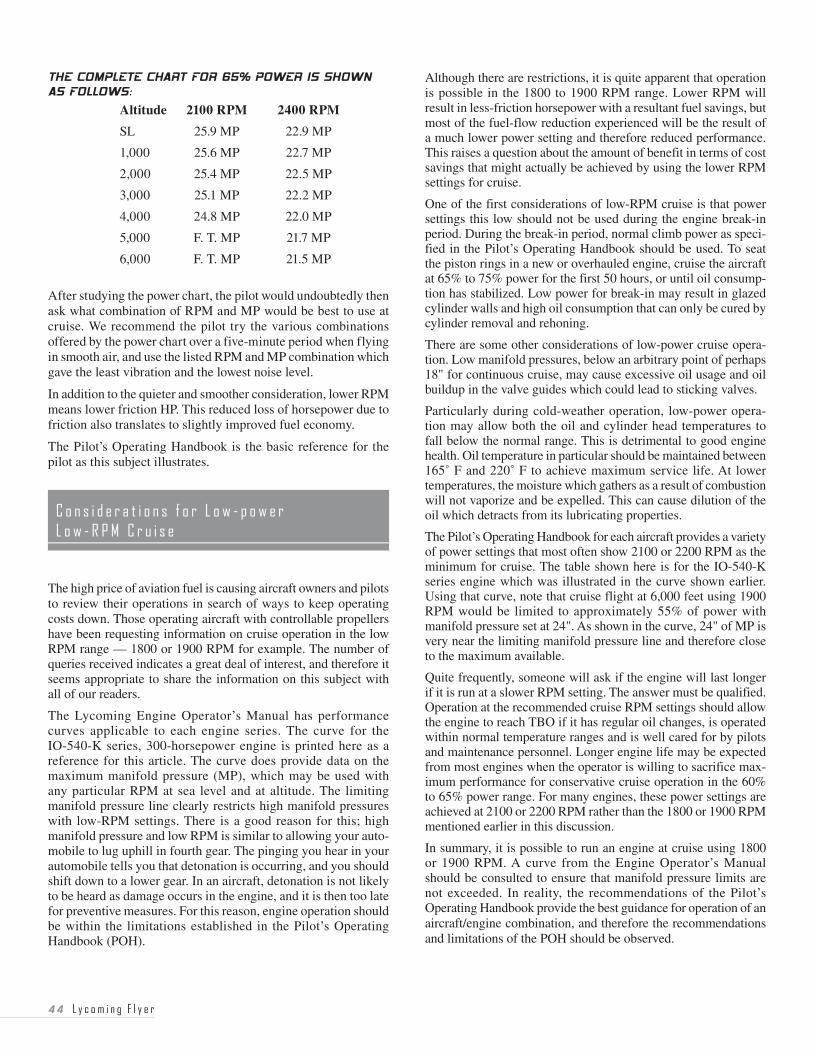
THE COMPLETE CHART FOR ��% POWER IS SHOWN AS FOLLOWS:
Altitude 2100 RPM 2400 RPM
SL 25.9 MP 22.9 MP
1,000 25.6 MP 22.7 MP
2,000 25.4 MP 22.5 MP
3,000 25.1 MP 22.2 MP
4,000 24.8 MP 22.0 MP
5,000 F. T. MP 21.7 MP
6,000 F. T. MP 21.5 MP
After studying the power chart, the pilot would undoubtedly then ask what combination of RPM and MP would be best to use at cruise. We recommend the pilot try the various combinations offered by the power chart over a five-minute period when flying in smooth air, and use the listed RPM and MP combination which gave the least vibration and the lowest noise level.
In addition to the quieter and smoother consideration, lower RPM means lower friction HP. This reduced loss of horsepower due to friction also translates to slightly improved fuel economy.
The Pilot’s Operating Handbook is the basic reference for the pilot as this subject illustrates.
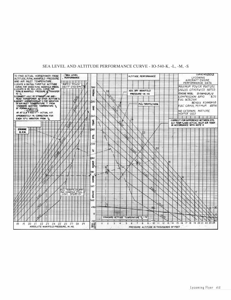
The high price of aviation fuel is causing aircraft owners and pilots to review their operations in search of ways to keep operating costs down. Those operating aircraft with controllable propellers have been requesting information on cruise operation in the low RPM range — 1800 or 1900 RPM for example. The number of queries received indicates a great deal of interest, and therefore it seems appropriate to share the information on this subject with all of our readers.
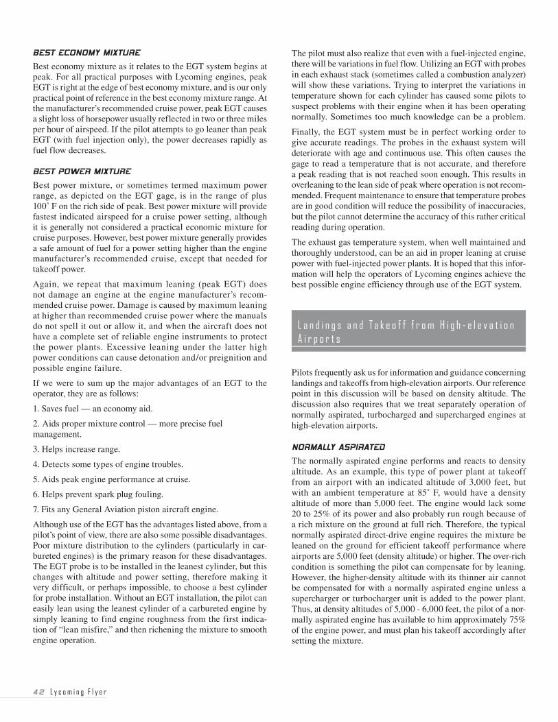
The Lycoming Engine Operator’s Manual has performance curves applicable to each engine series. The curve for the IO-540-K series, 300-horsepower engine is printed here as a reference for this article. The curve does provide data on the maximum manifold pressure (MP), which may be used with any particular RPM at sea level and at altitude. The limiting manifold pressure line clearly restricts high manifold pressures with low-RPM settings. There is a good reason for this; high manifold pressure and low RPM is similar to allowing your auto-mobile to lug uphill in fourth gear. The pinging you hear in your automobile tells you that detonation is occurring, and you should shift down to a lower gear. In an aircraft, detonation is not likely to be heard as damage occurs in the engine, and it is then too late for preventive measures. For this reason, engine operation should be within the limitations established in the Pilot’s Operating Handbook (POH).
Although there are restrictions, it is quite apparent that operation is possible in the 1800 to 1900 RPM range. Lower RPM will result in less-friction horsepower with a resultant fuel savings, but most of the fuel-flow reduction experienced will be the result of a much lower power setting and therefore reduced performance. This raises a question about the amount of benefit in terms of cost savings that might actually be achieved by using the lower RPM settings for cruise.
One of the first considerations of low-RPM cruise is that power settings this low should not be used during the engine break-in period. During the break-in period, normal climb power as speci-fied in the Pilot’s Operating Handbook should be used. To seat the piston rings in a new or overhauled engine, cruise the aircraft at 65% to 75% power for the first 50 hours, or until oil consump-tion has stabilized. Low power for break-in may result in glazed cylinder walls and high oil consumption that can only be cured by cylinder removal and rehoning.
There are some other considerations of low-power cruise opera-tion. Low manifold pressures, below an arbitrary point of perhaps 18" for continuous cruise, may cause excessive oil usage and oil buildup in the valve guides which could lead to sticking valves.
Particularly during cold-weather operation, low-power opera-tion may allow both the oil and cylinder head temperatures to fall below the normal range. This is detrimental to good engine health. Oil temperature in particular should be maintained between 165˚ F and 220˚ F to achieve maximum service life. At lower temperatures, the moisture which gathers as a result of combustion will not vaporize and be expelled. This can cause dilution of the oil which detracts from its lubricating properties.
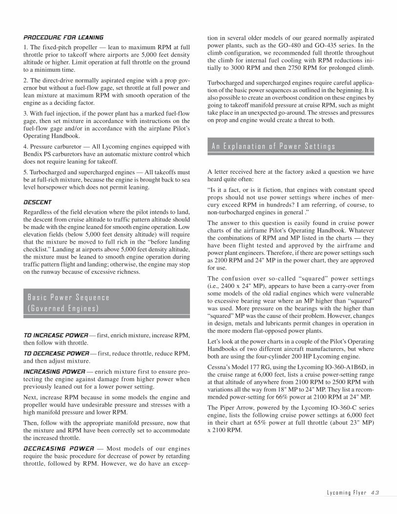
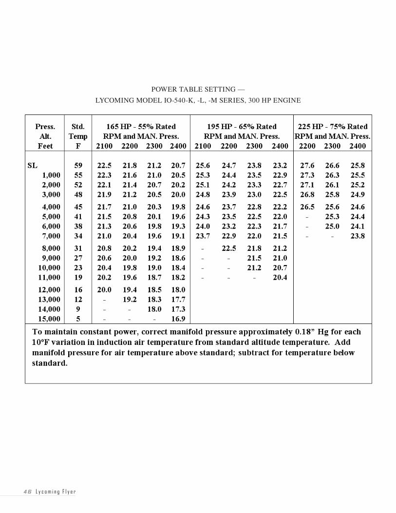
The Pilot’s Operating Handbook for each aircraft provides a variety of power settings that most often show 2100 or 2200 RPM as the minimum for cruise. The table shown here is for the IO-540-K series engine which was illustrated in the curve shown earlier. Using that curve, note that cruise flight at 6,000 feet using 1900 RPM would be limited to approximately 55% of power with manifold pressure set at 24". As shown in the curve, 24" of MP is very near the limiting manifold pressure line and therefore close to the maximum available.
Quite frequently, someone will ask if the engine will last longer if it is run at a slower RPM setting. The answer must be qualified. Operation at the recommended cruise RPM settings should allow the engine to reach TBO if it has regular oil changes, is operated within normal temperature ranges and is well cared for by pilots and maintenance personnel. Longer engine life may be expected from most engines when the operator is willing to sacrifice max-imum performance for conservative cruise operation in the 60% to 65% power range. For many engines, these power settings are achieved at 2100 or 2200 RPM rather than the 1800 or 1900 RPM mentioned earlier in this discussion.
In summary, it is possible to run an engine at cruise using 1800 or 1900 RPM. A curve from the Engine Operator’s Manual should be consulted to ensure that manifold pressure limits are not exceeded. In reality, the recommendations of the Pilot’s Operating Handbook provide the best guidance for operation of an aircraft/engine combination, and therefore the recommendations and limitations of the POH should be observed.
L y c o m i n g F l y e r ��
SEA LEVEL AND ALTITUDE PERFORMANCE CURVE - IO-540-K, -L, -M, -S
�� L y c o m i n g F l y e r
POWER TABLE SETTING —
LYCOMING MODEL IO-540-K, -L, -M SERIES, 300 HP ENGINE
L y c o m i n g F l y e r ��
The gasoline engine operates on a fuel/air mixture that is ignited by the spark plugs. Engines do not run when any of these ele-ments are missing. Pilots know positively that they must refuel the aircraft on a regular basis if they want to fly without incident, but the possibility of losing the air part of the fuel/air mixture is not always considered and understood as well as it should be. Perhaps the personal experience of several individuals, and some facts about induction-system icing can be used to help Flyer readers avoid an accident caused by lack of air for their engines.
Remember that any material that reduces or cuts off the flow of air in the induction system has the potential to cause a loss of power. A material failure of the air filter is one problem which is reported all too often. The filter is very necessary to keep dirt out of the engine; it must be inspected frequently and should be changed on some regular schedule. A filter which is several years old and has filtered the air during hundreds of hours of operation may be tired. One pilot reported that on turn-up of the engine before takeoff, he could not get the static RPM that his engine and fixed-pitch propeller should have produced. He wisely elected to return to the line and have the engine inspected. The air filter had pulled loose from its supporting frame and was lodged in the intake system where it was cutting off the air supply.
If this incident had occurred in flight, the engine would possibly not have been producing enough power to maintain altitude. Depending on the particular airframe, there are some options which might be utilized to regain some of the lost power. An alternate air system or carburetor heat system is designed into the induction system primarily to combat induction icing, but use of these systems may possibly help when intake air is blocked by other foreign materials. In some cases, just leaning the mixture may help to regain a little of the lost power.
Several years ago, there was a reported loss of engine power in heavy rain. In that case, a paper air filter was being used. When saturated with water, the paper filter element became swollen so that airflow was impeded. In this case, the use of carburetor heat to bypass the filter and releaning to achieve a better fuel/air mixture were successful tactics that kept the aircraft flying until a safe, on-airport landing could be made. We should keep in mind that it is not the ingestion of water through the engine that causes a serious loss of power; it is the reduced airflow.
Some pilots believe that fuel-injected engines are immune to induction icing. This is not so. Although the pilot flying with a fuel-injected engine does not have the same threat of icing at the venturi as those with a carburetor, rain, snow, slush and cold temperatures may cause a blockage (impact ice) to air flow in other parts of the induction system.
As an example, the pilot of a fuel-injected single reported flying at 11,000 feet in light drizzle. The temperature was slightly above
freezing and water readily ran off the windscreen. Although this would seem to be a no-problem situation, the engine started to lose power. After consideration of the available options, the manual alternate air system was activated. The engine immedi-ately regained power, and flight was continued to the home-base destination. After landing, the aircraft was taken into the hanger for examination. It was found that the air filter was covered with a layer of ice that had cut off the airflow. This is not an isolated or unusual case. When water is near freezing, movement of the water molecules may sometimes cause instantaneous freezing. This glazing over of the air filter is a known phenomena which pilots should expect and be ready to cope with. Again, bypassing the blockage of impact ice by use of alternate air proved to be a successful tactic for this pilot.
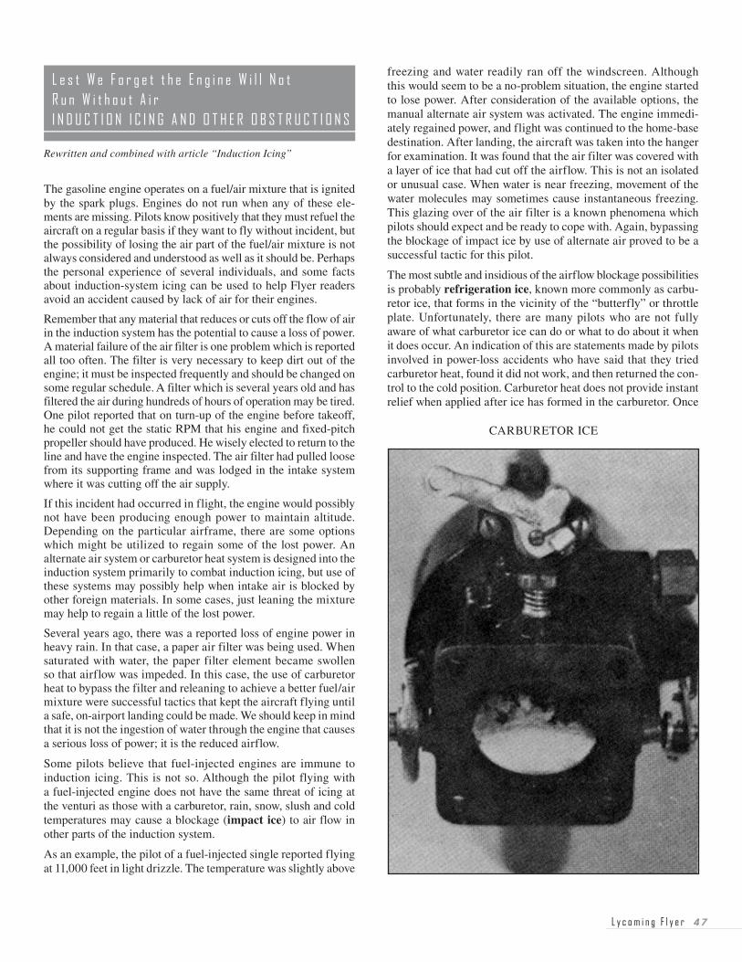
The most subtle and insidious of the airflow blockage possibilities is probably refrigeration ice, known more commonly as carbu-retor ice, that forms in the vicinity of the “butterfly” or throttle plate. Unfortunately, there are many pilots who are not fully aware of what carburetor ice can do or what to do about it when it does occur. An indication of this are statements made by pilots involved in power-loss accidents who have said that they tried carburetor heat, found it did not work, and then returned the con-trol to the cold position. Carburetor heat does not provide instant relief when applied after ice has formed in the carburetor. Once
Rewritten and combined with article “Induction Icing”
CARBURETOR ICE
�8 L y c o m i n g F l y e r
heat is applied, it should be left on until engine power returns. Left uncorrected, ice accumulation in the carburetor may cause complete engine stoppage.
Every pilot who flies an aircraft powered by a carbureted engine should be thoroughly educated about carburetor ice. They should know that under moist conditions (a relative humidity of 50% to 60% is moist enough), carburetor ice can form with any outside air temperature from 20˚ to 90˚ F. It is most likely in the 30˚ to 60˚ F range. Temperatures in the carburetor can drop 60˚ to 70˚ F (refrigerator effect) as a result of fuel vaporization and the carburetor venturi effect. It also happens that carburetor ice forms more readily when the engine is operated in the lower power range. It will form while taxiing, and this makes it very important to check engine power before takeoff and to remove the ice if necessary. Care should be taken to avoid dusty or dirty conditions when utilizing carburetor heat on the ground.
Next, it is imperative that the pilot recognize carburetor ice when it forms during flight. The loss of power that occurs will cause a reduction of RPM when flying with a fixed-pitch propeller, and a loss of manifold pressure when a controllable-pitch propeller is used. In either case, a loss of altitude or airspeed will occur. These symptoms may sometimes be accompanied by vibration or engine roughness. In any case, it is a good idea to consider carburetor ice as the cause of any unexplained power loss during cruise flight.
Once a power loss is noticed by the pilot, immediate action should be taken to eliminate ice which has already formed in the carburetor, and to prevent further ice formation. This is accomplished by applying full carburetor heat which will initially cause a further loss of power (perhaps as much as 15%) and pos-sibly, engine roughness. The additional power loss is caused by the heated air that is being directed into the induction system. Heated air makes the mixture richer and also melts the ice which then goes through the engine as water. The throttle may be advanced and the mixture may be leaned to help get some of the lost power back, but immediately after the application of carbu-retor heat, the pilot must be patient and keep the airplane flying until the ice has completely melted and normal power returns. How long this will take depends on the severity of the icing, but the pilot should expect a delay of 30 seconds to several minutes. Under the circumstances, this period of time will be stressful and always seems longer than it really is, but the knowledgeable pilot will not retreat from use of carburetor heat. Carburetor heat should remain in the hot position until power returns.
In conditions where carburetor ice is likely to form, the pilot may use heat during cruise to prevent the formation of ice in the carburetor. It is also appropriate to use full carburetor heat, if needed, to prevent icing when operating at low power for instrument approaches, or for flight in the traffic pattern. Unless the aircraft is equipped with a carburetor air temperature (CAT) gage, and very few general aviation aircraft are, use of full carburetor heat is recommended. An unknown amount of partial heat can actually cause induction ice in the float-type carburetor. This may occur when moisture in crystal form in the incoming air that would ordinarily pass through the induction
system without any problem is melted by the partial heat. This moisture then freezes when it comes in contact with the cold metal of the throttle plate.
Whenever carburetor heat is used in the landing configuration, and a go-around or touch-and-go takes place, there are some important steps for the pilot to remember. The throttle must be advanced, and the carburetor heat lever placed in the cold posi-tion. The order in which these steps are accomplished is not too important, but both must be done. Leaving the carburetor heat on during a go-around will result in a loss of power that could be critical at low altitude and low airspeed.
Do not use carburetor heat for takeoff or climb with a Lycoming engine as it is not necessary, and it may bring on detonation and possible engine damage. An exception to this rule might be justified in extremely cold-weather conditions such as those found in the Arctic, and these conditions require a special knowl-edge to accommodate operation under such extreme conditions.
A review of the material discussed in this article should help pilots cope with reduction of engine power when it is caused by loss of intake air for combustion. A thorough understanding of the air intake system and the knowledge to competently deal with induc-tion icing are essential to safe flight in general aviation aircraft. Pilots are encouraged to enhance the safety of their flying by knowing what to expect and what steps to take when the airflow to the engine is cut off for any reason.
A note that came in the mail from a Flyer reader included a suggestion that went something like this, “How about an article dealing more extensively with the cold-start problem?” This suggestion was a good one as it provided an opportunity to share information about a variety of cold-weather considerations to help get the engine started and to keep it operating during cold-weather conditions.
Although the suggestion made in the first paragraph was aimed at helping with cold-weather starting, this article has been expanded to include tips and information on preflight, starting, in-flight safety and engine operational considerations. Keep in mind that this material deals with normal cold-weather operation experi-enced at temperatures to -25˚ F, and not the extremely low tem-peratures that may be found in Arctic regions. Operation in those regions may require more specialized knowledge.
Let’s start with the general health of the engine. When attempting a start under adverse conditions, it is imperative that the engine be well maintained and in excellent operating condition. Spark plugs and magneto points should be properly gapped and ready to function effectively. In addition to the ignition system, the proper functioning of other systems such as induction, priming, exhaust and carburetor heat can have an effect on the starting and operation of the engine.
L y c o m i n g F l y e r �9
Regular maintenance should include having the heating system checked for leaks. This cold-weather tip is worthy of a sepa-rate little sentence all its own — remember, you can’t smell carbon monoxide.
In cold weather, preheat is another factor that must be consid-ered prior to starting the engine. There are specific guidelines in Lycoming service instructions which establish when preheat should be used, but how much, or the method of preheat is generally left to the good judgment of the pilot or maintenance person doing the preheating. Use of the heated dip stick is not recommended by Lycoming, although most other methods are considered to be satisfactory. For most Lycoming models, preheat should be applied anytime temperatures are at 10˚ F or lower. The exception to this rule is the 76 series models that include the O-320-H, and the O/LO-360-E. These engines should be preheated when temperatures are below 20˚ F. It is recommended that these guidelines be followed even when multi-viscosity oil is being used. In addition to hard starting, failure to preheat the entire engine and oil supply system as recommended may result in minor amounts of abnormal wear to internal engine parts, and eventually to reduced engine performance and shortened TBO time.
Water is one of the most likely contaminants of aviation gaso-line. The engine will not run on water, and although we may get away with small amounts of moisture in the fuel during warm weather, flight into freezing temperatures makes any amount of moisture in the fuel system very critical. Even a tiny bubble of moisture may freeze in the fuel line and totally cut off the flow of fuel. Two steps should be taken to avoid this problem. First, avoid water contamination if possible. Keep fuel tanks full to prevent condensation, and be sure fuel caps do not allow leakage if the aircraft is parked outside in rain or snow. Second, look for contamination before every flight by religiously draining fuel tanks and sumps.
If flight is planned for bad weather, the preflight inspection should include observation of the relief opening in the engine breather tube so that any freezing of moisture at the end of the breather will not result in a loss of engine oil. (See “The Whistle Slot” in this book.)
Once on board the aircraft, check the fuel-selector valve for freedom of movement. It may be frozen fast (this has happened), and you’d better find out while still on the ground.
Most of the time, we think of starting any engine as a very simple process. Just engage the starter, and listen for the engine to start purring. Unfortunately, when the weather turns cold, it is not always that simple. When dealing with a reciprocating aircraft engine, it may be essential to get a start on the first try in order to avoid icing over the spark plugs and making an immediate start impossible. In order to achieve a start on the first try, there are a number of factors to be considered. Those factors will be discussed in the following paragraphs.
Although it might be good procedure to use an external power source for starting during very cold weather, most of us expect our battery to do the job. We should remember that the battery is handicapped by cold weather. Particularly when a single-viscosity oil is being used, the colder the temperature, the more cranking
energy required. Combine this with reduced battery output at lower temperatures, and it can be a serious handicap.
While on the subject of batteries, remember that freezing tem-peratures provide a perfect opportunity to destroy an aircraft bat-tery. The battery with a full charge survives nicely, but one that is discharged will freeze. Once this happens, the problem can only be remedied by replacing the battery, so it is very worthwhile to take preventive measures. Should the battery be run down during an attempt to start, do not leave it; get it charged immediately. And finally, be absolutely certain that the master switch is always OFF while the aircraft is parked between flights. If left on, the battery will discharge and freeze. These rather minor mistakes can be quite expensive.
Oil is another factor to be considered in the cold-weather starting process. All oils are affected by temperature and tend to thicken as the temperature drops. The engine may be reluctant to turn over when the oil is stiff; a summer weight oil is not suitable in cold weather. It is also the condition which brings out the primary advantage of multiviscosity oils and of preheating. Because multi-viscosity oils are thinner (lower viscosity), they allow the engine to be turned over more easily. The easier and quicker oil flow also promotes faster lubrication of internal engine parts when the engine does start. Since the proper oil viscosity is so important in all aspects of engine starting and operation, the recommendations of oil grade vs. temperature range shown in Lycoming Service Instruction No. 1014 should be followed.
Probably the most important factor in starting an engine is achieving a fuel/air mixture that is satisfactory for combus-tion. Since the engine usually starts very easily, many pilots are unaware of or ignore the change of starting procedure needed to successfully start under varying temperature conditions. In warm weather, the air is less dense, and therefore must be mixed with a lesser amount of fuel than in cold weather. In addition to this, in warm weather, the fuel will vaporize readily and make starting easier. Simply stated, as temperatures go down it becomes more and more important that we have a plan for priming that will achieve the correct fuel/air mixture.
When priming a carbureted engine, the pilot’s plan must consider the temperature, the number of cylinders which have priming lines installed, and the number of strokes of the primer needed to produce the correct fuel/air mixture. The primer lines are ordered or installed by the airframe manufacturer and not all aircraft are configured the same. Some aircraft have actually been produced with only one cylinder being primed, and these engines are extremely hard to start in cold weather. The number of cylinders that are primed must be considered since the total fuel delivered by the primer will be divided and sent to these cylinders. As the air becomes colder and denser, the amount of prime used must be increased, but the number of strokes to be used should be planned as a result of some trial and error experimentation for each aircraft a pilot flies. When the cor-rect number of primer strokes for each temperature range has been established, the engine will usually start very quickly. We may find that an engine starts easily when one stroke of the primer is used in the 60˚ range, two strokes in the 50˚ range, three strokes in the 40˚ range, etc. This is an example of the
�0 L y c o m i n g F l y e r
trial and error we might use to establish the number of primer strokes to use under any particular temperature condition.
While discussing the priming of an engine, there have been situ-ations where primer lines become clogged. This makes engine starting difficult and negates any trial and error experimentation that may have been done. When maintenance is done on an aircraft before the start of winter, it may be wise to have those primer lines checked to ensure that fuel will flow through them.
The amount of fuel needed to achieve the correct fuel/air mixture for starting a fuel-injected engine is controlled by timing rather than number of primer strokes. With the electric fuel pump on, moving the mixture control to the rich position allows fuel to flow to the cylinders. For cold-weather starting, it may be neces-sary to keep the mixture control in rich somewhat longer than in warm weather.
The fuel part of the fuel/air mixture may be the part we have the most control over during the engine start, but keep in mind that the amount of throttle opening does have an effect on the air that is pumped through the engine. Just as we compensate for cold/dense air by adding more fuel for start, it may also be appropriate to reduce the air part of the mixture when the tem-perature is very cold. For example, if the throttle is normally set open one-half inch for warm weather starting, it may be helpful to reduce this to one-quarter inch in cold weather. Again, it will require some experimentation to determine what is needed to achieve the correct fuel/air mixture for any particular aircraft at any temperature range.
When an engine does not start easily, it can be frustrating. Of course, this can occur at any time of the year, and it is very tempting to just keep grinding away with the starter in an attempt to get it going. Should this happen to you, RELAX. Take care of that starter, or it may fail. The general rule for starters is that they should only be operated for short periods, and then allowed to cool. If engine start has not occurred after three 10-second periods of operation with a pause between each, a five-minute cooling off period is required. Without this time limit for operation and an adequate cooling off period, the starter will overheat and is likely to be damaged or to fail completely.
The previous paragraphs have addressed several issues that relate to the cold-weather preflight and the cold-weather start. There are other cold-weather items that should be considered in the operation of the engine.
Assuming the engine has kicked off, check for an indication of oil pressure. Learn the characteristics relative to response of oil pressure indications of your aircraft/engine combina-tion. On most single-engine aircraft, an almost immediate response is noted. On twin-engine aircraft, the response may be much slower. On some twins, the oil pressure may go up, and during warm-up, may drop again for a short period of time, then again rise to normal. All cases mentioned may be normal, but the important thing is to know what to expect from your aircraft/engine combination.
After start, do not idle engine below 1000 RPM. It’s not good practice to idle engines below 1000 RPM at any time. This is particularly true during cold weather to prevent lead fouling of spark plugs. (Exception — Piper Pressurized Navajo)
Now, here’s a tip for novice pilots. When setting up for cruise configuration, be precise, read your instruments and remember what you read. Example: If you decide on 22" of manifold pres-sure, set it right on 22. If the RPM is to be 2350, make it 2350. Select an altitude. Trim the aircraft to hold that selected altitude. Note airspeed. Now, if anything changes, barring turbulent air, it has to be a change in power. Perhaps it is carburetor or induction-air icing. Suppose you picked up a bit of carburetor ice, and the engine suffers a slight power loss. There will be a slight drop in manifold pressure, a loss in airspeed, and the aircraft will want to lose altitude, and if you hold altitude, you’ll find back pressure on the wheel is required. Therefore, even though you didn’t discover the power loss through instrument scanning, you’ll get a warning through the “heavy” wheel or stick.
During flight in very low temperatures, exercise constant speed props about every 30 minutes to help prevent congealing of oil in the prop dome.
Should one engine of a twin, for any reason, indicate the prop must be feathered, don’t tarry too long with reduced power in very cold weather. At reduced power, the oil may congeal making feathering an impossibility.
A tip for every pilot, don’t run one set of fuel tanks nearly dry before switching tanks. Switch with plenty of fuel remaining in the tanks first used. This is “money in the bank,” should you find the selector valve frozen.
Although carburetor ice is not necessarily a wintertime phenomena, a check of carburetor heat should be made during the engine run-up. Generally speaking, we can say that carburetor heat should never be used for takeoff, but there is one exception. This exception occurs when operating in temperatures so cold that application of carburetor heat produces a rise in RPM. Most pilots will never find themselves in circumstances which require use of carburetor heat for takeoff and climb; those who fly carbureted engines will almost certainly have occasion to use carburetor heat during cruise or let down. Use of the full-hot or full-cold position is recommended. An intermediate setting should only be selected if the aircraft is equipped with a carburetor air temperature (CAT) gage.
Engine operating temperature is another item that is not usu-ally given enough consideration in cold weather. We usually are very cautious about high oil temperature which we know is detrimental to good engine health, while a low oil temperature is easier to accept. The desired oil temperature range for Lycoming engines is from 165˚ to 220˚ F. If the aircraft has a winteriza-tion kit, it should be installed when operating in outside air temperatures (OAT) that are below the 40˚ to 45˚ F range. If no winterization kit is supplied and the engine is not equipped with a thermostatic bypass valve, it may be necessary to improvise a means of blocking off a portion of the airflow to the oil cooler. Keeping the oil temperature above the minimum recommended temperature is a factor in engine longevity. Low operating temperatures do not vaporize the moisture that collects in the oil as the engine breathes damp air for normal combustion. When minimum recommended oil temperatures are not maintained, oil should be changed more frequently than the normally rec-ommended 50-hour change cycle. This is necessary in order to eliminate the moisture that collects and contaminates the oil.
L y c o m i n g F l y e r � �
And finally, power-off letdowns should be avoided. This is especially applicable to cold-weather operations when shock-cooling of the cylinder heads is likely. It is recommended that cylinder head temperature change not exceed 50˚ F. per minute. Plan ahead, reduce power gradually and maintain some power throughout the descent. Also keep the fuel/air mixture leaned out during the descent. If an exhaust gas temperature gage is installed with a normally aspirated engine, keep it peaked to ensure the greatest possible engine heat for the power setting selected; for a turbocharged installation, lean to peak during descent unless otherwise specified in the Pilot’s Operating Handbook, or under conditions where the limiting turbine inlet temperature would be exceeded.
Exposure to snow, frost and cold weather while flying requires the consideration of many factors, both airframe and engine related. This discussion deals with issues relating to the engine. While there may be other issues, those items which are asked about most frequently have been discussed. Safer flying and longer engine life could result from careful consideration of the material addressed.
The fatal crash of a light twin in which a flight instructor and an applicant for a multiengine rating were killed prompted the NTSB to issue an urgent warning to all pilots simulating an engine-out condition on multiengine airplanes. The Board’s investigation revealed that some flight instructors do use the fuel selector or the mixture control to shut down an engine to test a multiengine applicant. Although this is a recommended procedure, the urgent warning was aimed at flight instructors who were using this pro-cedure at altitudes too low for continued safe flight.
The NTSB observed that use of such procedures at traffic pattern altitudes may not permit instructors enough time to overcome possible errors on the part of the applicant. The recommenda-tion by the NTSB means that all simulated engine-out operation at the lower altitudes should be accomplished by retarding the throttle, and this should be done slowly and carefully to avoid engine damage or failure.
Many flight instructors down through the years used the tech-nique of abruptly cutting an engine with a multiengine can-didate to test his emotional reaction and judgment with this extreme technique. Big radial piston engines with short, stubby crankshafts could tolerate the abrupt technique. However, flat-opposed piston engines with their long crankshafts and attached counterweights could not as readily take the abuse of suddenly snapping a throttle shut, particularly at takeoff or climb power. Use of the latter technique would tend to detune crankshaft counterweights and could possibly result in a nasty engine failure.
Since it was common technique by flight instructors to termi-nate power abruptly to simulate an engine power loss, we had to protect the engine. As a result, we published in our Engine Operator’s Manual and in Service Bulletin No. 245, the recom-mendation that if the power was abruptly terminated, it must be accomplished with the mixture control. Of course, this was intended for the higher altitudes where a complete engine shut-down could be conducted safely. The student was to iden-tify the dead engine by retarding that throttle to about 12" MP to simulate zero thrust, or similar to having the prop feathered. At that point, the instructor could immediately return the mixture to an engine-operating condition, and power would be available if needed.
In our publications, we then explained the reason for using the mix-ture to abruptly terminate power. By putting the mixture control in idle cutoff position with the throttle in a normal open or operating position, the pilot merely cut off the fuel, but allowed the air to con-tinue to fill the cylinders with resulting normal compression forces that are sufficient to cushion the deceleration of the engine and prevent the detuning of the crankshaft counterweights.
However, any practice of simulated engine-out condition at low altitudes should be best accomplished by a slow retardation of the throttle in accordance with the NTSB recommendation. This careful technique will protect the engine, and at the same time, provide for instant power if it is needed.
Although the smal ler four-cyl inder engines of the low-compression, low-horsepower variety do not generally use a cylinder head temperature gage, the higher powered, more complex power plants require a cylinder head temperature gage in order to prevent unwitting abuse by the pilot.
If head temperatures are higher than normal during flight, it should not be ignored, because there is some reason for it. It may be caused by hot ambient temperatures, a lean fuel metering device at higher than cruise power, bad baffles or leaking cowling, or malfunctioning of the ignition system. Even old and tired engine mounts that allow the engine to sag slightly may cause a change in the airflow pattern and an abnormal increase in CHT. It is also possible that a mechanical problem may be developing in the engine.
When higher than normal cylinder head temperatures are showing on the gage, the pilot should take steps to bring the temperatures down to the normal operating range in order to keep the remaining flight safe. Head temperatures may be reduced by:
1. Enriching the mixture
2. Adjusting cowl flaps
3. Reducing power
4. Any combination of the above
�� L y c o m i n g F l y e r
We suggest that in order to help the mechanic diagnose the problem, the pilot or some member of the crew should make a written record of the engine instrument readings during the above flight condition and present it to the maintenance people.
A first step in diagnosing abnormal cylinder head temperatures would be ensuring that the gages are providing accurate readings. If they are, the mechanic can then proceed to check engine baffles that may have deteriorated, proper flow of the fuel metering device, and then other more time-consuming checks for ignition or mechanical malfunction.
The cylinder head temperature gage (CHT) helps the pilot pro-tect his engine against the threat of excessive heat. Most General Aviation aircraft take the CHT off the hottest single cylinder of the four- six- or eight-cylinder power plants determined by extensive flight tests. Optional installations offer readings from all cylinders. In Lycoming engines, all cylinders are drilled to accommodate a CHT bayonet-type thermocouple.
Some operators in the field have been using a spark plug gasket-type installation in order to get cylinder head tem-perature readings. Lycoming Engineering does not currently approve this method of determining CHT. Not only is the method less accurate than the recommended thermocouple type, but the temperature readings differ noticeably from the approved installations.
Minimum in-flight CHT should be 150˚ F (65˚ C), and maximum in most direct-drive normally aspirated Lycoming engines is 500˚ F (260˚ C). Some of our higher-powered more complex engines have a maximum limit of 475˚ F (245˚ C). Although these are minimum and maximum limits, the pilot should operate his or her engine at more reasonable temperatures in order to achieve the expected overhaul life of the power plant. In our many years of building engines, the engines have benefited during continuous operation by keeping CHT below 400˚ F in order to achieve best life and wear of the power plant. In general, it would be normal during all-year operations, in climb and cruise to see head tem-peratures in the range of 350˚ F to 435˚ F.
If an engine has bayonet probes in all cylinders, it is not unusual to see variations in CHT readings on fuel-injected engines of 100˚ F between cylinders, and as much as 150˚ F on engines with float-type carburetors. With the latter, an important cause of the variation is the kind of distribution of fuel and air to the individual cylinders. Other influences on CHT are such items as cylinder baffles, cowling, cowling flaps, location of engine accessories and, of course, manual control of fuel mixture.
It is very important that the CHT probes be checked on a regular basis. When these bayonet probes deteriorate, they tend to give readings that are less than the actual temperature of the cylinder head. This can result in operation above the recommended max-imum temperature without the pilot even knowing it.
Operators frequently ask about the difference between the CHT and EGT (exhaust gas temperature) systems, and their meaning to the pilot during operation of the engine or engines. The EGT probe is installed in a different location from the CHT, or about four inches from the cylinder head down the exhaust stack. Although the EGT has some troubleshooting ability, it is pri-marily a fuel-management instrument. On the other hand, the CHT is an engine instrument designed to protect the power plant against its enemy, excessive heat.
The present-day piston engine instruments used in the typical general aviation airplane are not precision laboratory instru-ments. We exclude the turbine and jet-powered aircraft from this discussion and will consider only piston engines, recognizing that the more expensive pressurized twin-engine models may also be exceptions.
Nevertheless, the purpose of this brief presentation is a practical approach to interpreting the readings of your engine instruments in accomplishing a safe and efficient flight. If, for example, you were to observe an irregular reading of one engine instrument, it calls for a cross-check on all other instruments, and not relying on one instrument as a basis for a decision affecting flight.
Since the engine is dependent on fuel, we consider the gasoline gage as a related engine instrument. If pilots are going to attempt to stretch their flight range close to limits, they should be aware of the errors in the gages vs. the actual usable fuel. Some modern single-engine aircraft have had the gas gage show several gallons remaining, when in reality, the tank was empty. Others have indicated a specific number of gallons when filled, but actually the tank held several gallons less than indicated.
Therefore, in planning for each flight, remember that general aviation engine instruments are not precision laboratory types, so cross-check, and give yourself an extra margin for safety.
An important part of the engine-starting procedure is the priming technique. Of course, the Pilot’s Operating Handbook will specify the steps in starting a specific model engine. However, some of the pilot handbooks may not explain why certain procedures are used in the starting process.
Priming can be best accomplished with an engine priming system, as opposed to use of the throttle. The primer pumps extra fuel directly into the cylinder intake port or induction system. Some float-type and pressure carburetors also provide a supplemental source of priming. Lycoming engines of more than 118 HP have a throttle pump which can be used for priming under moderate ambient temperature conditions while turning the engine with the starter.
L y c o m i n g F l y e r ��
Pilots should, however, be advised that excessive throttle priming can cause flooding of the carburetor and airbox, and result in a fire in the induction system or on the outside where the fuel drains overboard. If the operator floods the engine by pumping the throttle and has a fire, it is possible to handle such a fire in the early stages by continuing to turn the engine with the starter, thereby sucking the fire back into the engine. Furthermore, if there is any fire on the outside of the engine, if the engine starts, there is a good chance it will blow out the external fire.
If there is flooding of the engine without a fire, the operator should open the throttle full and close the mixture; (see Operator’s Handbook on mixture) turn the engine over several times with the starter to clear it; then begin again with a normal start routine.
Most Lycoming fuel-injected engines are simply primed by turning the fuel boost pump on, opening the mixture briefly to full rich, and cracking the throttle. Any pumping of the throttle is ineffective until the engine begins to fire.
FUEL CONTAMINATION — Water (says the FAA) is the principal contamination of aviation fuel. For a safe flight, carefully drain fuel sumps at each preflight.
As an engine manufacturer, we are frequently asked about the proper use of the fuel boost pump with our power plants. Although we can’t pretend to be an expert on the fuel boost pump itself, we have some positive recommendations concerning its use with our engines. Where a boost pump is provided by the airframe manufacturer, and the airframe Pilot’s Operating Handbook has a limited treatment of the use of the fuel boost pump, perhaps this discussion can provide the necessary fuel boost pump information for the pilot in order to operate his or her engine as safely as possible.
It is necessary to supply the engine with a steady, uninterrupted flow of fuel for all operating conditions. Entrapped air, tempera-ture changes, pressure drops, agitation in the fuel lines and other factors affect the release of air and vapor from the fuel system. Under some circumstances where an engine-mounted fuel pump is provided, it may not be able to pump a continuous fuel supply free of excessive vapor.
An effective continuous fuel supply is provided by use of the fuel boost pump. As a general recommendation, the fuel boost pump should be used with Lycoming engines in all conditions where there is any possibility of excessive vapor formation, or when a temporary cessation of fuel flow would introduce undesirable hazards. The conditions under which Lycoming recommends operation of the fuel boost pump are as follows:
1. Every takeoff.
2. Climb after takeoff unless Pilot’s Operating Handbook says it is not necessary.
3. When switching fuel selectors from one separate fuel tank to another, the fuel boost pump should be “on” in the new tank until the operator is assured there will be no interruption of the fuel flow.
4. Every landing approach.
5. Any time the fuel pressure is fluctuating, and the engine is affected by the fluctuation.
6. Hot weather, hot engine ground operation where fuel vapor problems cause erratic engine operation.
7. Some General Aviation aircraft require the use of the fuel boost pump during high-altitude flight. This will be spelled out in the Pilot’s Operating Handbook.
8. If the engine-mounted fuel pump fails.
If the fuel boost pump is used during ground operation, don’t fail to check the condition of the engine-mounted fuel pump before takeoff by turning the boost pump off briefly, and then back “on” for takeoff. If the engine-mounted pump has failed, it would be safer to know that on the ground rather than in the air when the fuel boost pump is turned “off.”
When in doubt, do the safest thing and use the fuel boost pump with Lycoming engines. Don’t be “stingy” with the boost pump. In most cases, they last the overhaul life of the engine, and are then exchanged or overhauled themselves. AS A REMINDER, the airframe Pilot’s Operating Handbook is the authority if boost pump information is spelled out in it.
Sudden cooling is detrimental to the good health of the piston aircraft engine. Lycoming Service Instruction 1094D recommends a maximum temperature change of 50˚ F per minute to avoid shock-cooling of the cylinders.
Operations that tend to induce rapid engine cooldown are often associated with a fast letdown and return to the field after dropping parachutists or a glider tow. There are occasions when Air Traffic Control also calls for fast descents that may lead to sudden cooling.
The engine problems that may be expected when pilots consis-tently make fast letdowns with little or no power include:
1. Excessively worn ring grooves accompanied by broken rings.
2. Cracked cylinder heads.
3. Warped exhaust valves.
4. Bent pushrods.
5. Spark plug fouling.
Generally speaking, pilots hold the key to dodging these prob-lems. They must avoid fast letdowns with very low power (high-cruise RPM and low manifold pressure), along with rich
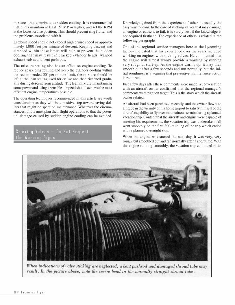
�� L y c o m i n g F l y e r
mixtures that contribute to sudden cooling. It is recommended that pilots maintain at least 15" MP or higher, and set the RPM at the lowest cruise position. This should prevent ring flutter and the problems associated with it.
Letdown speed should not exceed high cruise speed or approxi-mately 1,000 feet per minute of descent. Keeping descent and airspeed within these limits will help to prevent the sudden cooling that may result in cracked cylinder heads, warped exhaust valves and bent pushrods.
The mixture setting also has an effect on engine cooling. To reduce spark plug fouling and keep the cylinder cooling within the recommended 50˚ per-minute limit, the mixture should be left at the lean setting used for cruise and then richened gradu-ally during descent from altitude. The lean mixture, maintaining some power and using a sensible airspeed should achieve the most efficient engine temperatures possible.
The operating techniques recommended in this article are worth consideration as they will be a positive step toward saving dol-lars that might be spent on maintenance. Whatever the circum-stances, pilots must plan their flight operations so that the poten-tial damage caused by sudden engine cooling can be avoided.
Knowledge gained from the experience of others is usually the easy way to learn. In the case of sticking valves that may damage an engine or cause it to fail, it is surely best if the knowledge is not acquired firsthand. The experience of others is related in the following paragraphs.
One of the regional service managers here at the Lycoming factory indicated that his experience over the years included working on engines with sticking valves. He commented that the engine will almost always provide a warning by running very rough at start-up. As the engine warms up, it may then smooth out after a few seconds and run normally, but the ini-tial roughness is a warning that preventive maintenance action is required.
Just a few days after these comments were made, a conversation with an aircraft owner confirmed that the regional manager’s comments were right on target. This is the story which the aircraft owner related.
An aircraft had been purchased recently, and the owner flew it to altitude in the vicinity of his home airport to satisfy himself of the aircraft capability to fly over mountainous terrain during a planned vacation trip. Content that the aircraft and engine were capable of meeting his requirements, the vacation trip was undertaken. All went smoothly on the first 300-mile leg of the trip which ended with a planned overnight stop.
When the engine was started the next day, it was very, very rough, but smoothed out and ran normally after a short time. With the engine running smoothly, the vacation trip continued to its
L y c o m i n g F l y e r ��
destination. The aircraft was then tied down and not operated until it was time for the return trip — a period of about one week.
As the engine was started for the return trip, it again gave indica-tions that a valve was momentarily sticking ... it ran very rough for several seconds, but then smoothed out. With the engine running smoothly again, the return trip was started. After one to two hours of flight at altitude, over mountainous terrain, the engine ran very rough again for a short period of time, and then smoothed out. The pilot decided to land at the nearest airport.
Examination of the engine revealed a considerable amount of oil leakage. The cause — a valve which had stuck solidly and caused the pushrod to bend. This bending ruptured the pushrod shroud tube and allowed oil to escape. This is a classic example of the damage that sticking valves can cause.
The lesson to be learned is quite simple. Do not neglect the warning signs. Perhaps the experience related here will allow others to recognize a rough-running engine at start-up as a pos-sible indication of sticking valves. The next step is to take imme-diate action to prevent damage.
Although there may be an occasional exception, it is almost always an exhaust valve that sticks. To prevent further valve sticking and to reduce the possibility of damage, all exhaust valve guides should be cleaned of any carbon, varnish or other contamination buildup. This is accomplished by reaming the guides to their original size as specified in Lycoming Publication SSP 1776, Table of Limits. The latest revision of Lycoming Service Instruction 1425 provides recommendations to reduce the possibility of valve sticking. In particular, Part III of the instruction gives a procedure for reaming valve guides that can be accomplished without removing the engine from the aircraft or the cylinders from the engine.
Considering that the properly timed sequence of valve opening and closing is essential to efficient and reliable engine operation. Anytime those valves stick for any reason, it is a serious problem. Therefore, the purpose of this article is to provide our readers with some insight into this problem along with methods to help avoid it.
The space between the continuously moving valve stem and its stationary valve guide is extremely critical. Note that the amount of clearance can be affected by high temperatures, engine clean-liness and extended periods of engine inactivity. Changes in valve-to-guide clearance can occur during the course of engine operation. In other words, a sticking or broken valve may not be the fault of the engine. It is possible to promote valve sticking, and there are actions that can be taken to reduce or eliminate the possibility of this phenomena. These actions will affect engine cooling, fuel management and internal engine cleanliness.
Engine cleanliness is a primary consideration that is affected by many maintenance and operational procedures. Proper filter maintenance is one such item. The induction air filter is the first
line of defense in keeping dirt and abrasives from entering the engine. To prevent dirt from entering the engine, the filter must form a good seal with the filter holder, and the induction system should be free of air leaks. The air filter should be cleaned or changed on a regular basis. In extremely dusty conditions, a filter change could be necessary as frequently as every few hours of operation.
The second line of defense against dirt and abrasives is the full-flow oil filter that is standard with most Lycoming engines now being produced. Older engines were manufactured with a pressure screen, but may be converted to a full-flow filter for more effective cleaning of the oil. Lycoming Service Publication SSP-885-2 provides information and instructions needed for this conversion.
Another contributor to a variety of engine problems, including valve sticking, is frequent long periods of inactivity. An engine should be flown regularly to stay in tiptop condition. The oil in the sump collects residue from combustion such as moisture, acid and lead sludge. Flying the aircraft tends to heat the oil enough to vaporize the moisture and help eliminate some of these contaminants, but an engine that is not flown will col-lect moisture, acids and gums which may contribute to corro-sion and to valve-train problems. In addition to frequent flight, these contaminants are also eliminated from the engine by changing the oil. Lycoming Service Bulletin No. 480 makes these recommendations for engines operating under normal (non-dusty) conditions:
a. 50-hour interval oil change and filter replacement for all engines using a full-flow filtration system.
b. 25-hour interval oil change and screen cleaning for all engines employing a pressure-screen system.
c. A total of four months maximum between oil changes for either of the systems discussed under a. and b., even if the engine is not flown.
Reports from aircraft owners continue to indicate that trouble-free operation through TBO is most often obtained with engines subjected to frequent oil change intervals. Absurd as it may seem, an engine which does not fly regularly should have the oil changed at more frequent flight time intervals than one that does fly regularly.
Preventing a buildup of contaminants is just as important as eliminating those that do form. Avoiding long periods of ground operation is a vital step since moisture can enter the breather, but will not vaporize when the oil is not heated to normal oper-ating temperatures. Ground running also involves a slightly rich mixture which contributes to the formation of lead sludge in the oil. During flight, the deposit of lead sludge in the oil can be minimized by proper leaning.
Although some excess fuel is required for engine cooling during high-power operation, proper leaning at cruise-power settings will promote complete burning of the fuel and, therefore, a minimum of lead sludge deposited in the oil. This is important since lead sludge is not filtered out, but is removed by changing the oil. The airframe manufacturer’s recommendations and limitations for leaning should be observed, but it may be beneficial to be aware
�� L y c o m i n g F l y e r
that when permitted by the Pilot’s Operating Handbook, leaning to peak EGT at cruise-power settings will produce complete burning of the fuel/air mixture for best economy and reduction of combustion-related contaminants.
Having touched on fuel management and maintenance items required to keep an engine clean internally, the final factor affecting potential valve sticking is engine operating tempera-ture. Some operating procedures already discussed also have an effect on engine temperature. Prolonged engine ground run-up at high-power settings, for example, can cause engine overheating or hot spots since cooling airflow is not always adequate when the aircraft is stationary.
Since proper engine operating temperatures fall within a min-imum and maximum range, it is important to consider all aspects. It must be emphasized that baffles designed to direct cooling air over the cylinders must be maintained in good condition. They play an extremely important role. If these baffles deteriorate or are installed so that cooling air is not adequately contained and directed, hot spots which promote a lead or carbon buildup may occur. During hot weather in particular, those baffles or ducts that direct cooling air through the oil cooler must also be maintained in good condition.
The pilot, as well as maintenance personnel, will play an impor-tant role in ensuring that engine operating temperatures do not promote valve sticking. As mentioned earlier, ground running far in excess of the time necessary for engine warm-up should be avoided. Also to be considered is continuous operation at very low aircraft speeds that may not generate the most efficient flow of cooling air over the engine. This lack of effective cooling air may cause some areas of the engine to be excessively hot, and therefore have an effect on any contaminants that are in the oil. The formation of deposits is promoted, with the exhaust valve guide area the most likely to be affected. The result of these deposits may be a stuck or sticking valve.
The other end of the spectrum controllable by the pilot is exces-sively rapid cooldown of an engine that has been running at normal operating temperatures. Lycoming engines are made with various metals that expand and contract at different rates when exposed to heat or cold. It is poor technique to “chop” the power from cruise or higher power settings to idle and then start a rapid letdown which develops excessive cooling airflow over the engine. It is always best to reduce power in increments so that engine temperature changes will occur gradually. It is also beneficial to continue the engine cooling process after landing by ensuring that several minutes of engine operation at 800 to 1200 RPM are allowed before shutdown. At large airports, this is usually accomplished by the time taxi to the parking area is completed. At airports where clearing the runway puts the aircraft in the parking area, a short period of additional operation in the 800 to 1200 RPM range prior to engine shutdown will allow temperatures to stabilize.
A logical question after this long series of things to do and things not to do might be this, “Is there any way to tell if a valve is sticking before serious damage occurs?” There are sometimes warning signs that should be investigated. Although there may be other causes, an intermittent hesitation or miss in the engine
may be an indication that carbon or other similar contaminants have built up inside the valve guide causing the valve stem to drag instead of moving freely. These contaminants should be removed by reaming the guide to the size specified in the Lycoming Table of Limits (SSP 1776). The procedure to be used when reaming to remove valve guide deposit buildup is found in Lycoming Service Instruction 1425. Known as “the old rope trick” to many A&P mechanics, this valve guide reaming pro-cedure restores valve stem to guide running clearance and can be accomplished without removing the engine from the aircraft.
To summarize, procedures to reduce valve sticking will also reduce the probability of additional engine damage which may cause loss of power and the need for costly repairs. These proce-dures may be reduced to relatively simple terms: The maintenance and operational procedures necessary to avoid sticking valves are those that keep the engine clean internally and which cause it to run within proper operating temperature ranges. The items discussed above should serve as a guide for A&P mechanics and for pilots.
These are some of the more common questions asked at our service hanger:
QUESTION: Do your new, rebuilt or overhauled engines require a break-in period that consists of cruise at low-power settings?
ANSWER: Definitely not. Fly them as you would a high-time engine. In fact, so-called “slow” flying may have harmful effects. The rings may not seat properly resulting in higher than normal oil consumption.
QUESTION: At what rate of oil consumption does continued operation of the engine become a hazard?
ANSWER: Generally speaking, when the oil consumption reaches one quart per hour, corrective action should be taken. However, maximum permissible for each particular engine is listed in the engine operator’s manual.
QUESTION: What are the dangers of operating an engine with high oil consumption?
ANSWER: When excessive amounts of oil get past the rings, there is danger of the ring sticking or breaking with a dramatic rise in oil consumption. Then oil soaked carbon forms at a fast rate. At the same time, the presence of oil in the combus-tion chamber has the effect of lowering the octane rating of the fuel. Operating temperatures go up. We have now set up conditions inviting detonation and/or preignition.
QUESTION: If I can’t get aviation fuel, may I use automotive fuel if octane rating is equal or higher?
ANSWER: No. As an engine manufacturer, even the use of automotive fuel where an STC has been issued is considered risky and is not recommended. There are 4 or 5 good reasons
L y c o m i n g F l y e r ��
and all are important. They can be summed up in three words — potential engine failure.
QUESTION: What is the most common cause of premature engine wear?
ANSWER: Dirt in the air entering the engine through the carburetor or injector due to worn-out air filter, torn induction hoses or broken air boxes, and then being carried through the engine by the oil.
QUESTION: Does the spacer between the propeller and the engine serve any purpose other than streamlining the nacelle?
ANSWER: Yes. In many cases, moving the propeller forward, which increases the clearance between propeller and cowl, increases propeller efficiency and reduces nacelle vibration.
QUESTION: In some cases, we note a minor discrepancy between the engine operator’s manual and the airplane Pilot’s Operating Handbook. Which one should be followed?
ANSWER: The airframe Pilot’s Operating Handbook. For various reasons, after the engine is installed in the airframe, operational techniques may be altered or certain restrictions may be placed on the engine. A simple example would be a placard restricting continuous operation in a certain RPM range.
QUESTION: I fly an aircraft equipped with a fixed-pitch propeller. During cruise, I’m told to keep increasing the RPM as my cruising altitude is increased. Since I fly pretty high, in order to hold 65% power, I find the RPM is mostly at 2550 to 2600. Won’t this high RPM reduce the engine life?
ANSWER: No. The higher RPM won’t harm the engine or reduce service life. Remember, you are increasing the RPM only to hold the same power you had at a lower altitude at say, 2350 RPM.
QUESTION: Is there really any difference between good automotive oil and aviation oil?
ANSWER: Yes, indeed there is! Don’t ever use automotive oil in your aircraft engine. These oils are now blended for use with unleaded fuels, and the additives in auto oil cause problems in an aircraft engine that operates at much higher temperatures than the automobile engine. We have encoun-tered engines with holes burned in pistons due to the use of automotive oils that have an ash deposit causing preignition. It seems awfully hard to convince people who have had great success with the oil used in their car that it may not be used in their aircraft engine.
NOTE — Since we have had several questions on fuels and oils, it might be well to mention that we can’t think of a quicker way to void your engine warranty than by using anything other than the recommended and FAA-approved aviation fuels and oils.
QUESTION: What are some common causes of excessive oil consumption other than the burning of oil due to high engine time?
ANSWER: Building up of crankcase pressure due to “blow-by” caused by ring wear may result in oil being blown out of the breather. The same thing can result from broken piston rings. Oil
may be pumped overboard due to a faulty vacuum pump or faulty automotive-type fuel pump.
QUESTION: My dealer advised me to use straight mineral oil in my new engine until it’s “broken in.” How do I know when it’s “broken in”?
ANSWER: When oil consumption has stabilized. Example: After continued checking of oil consumption, you have deter-mined the engine is consistently using one quart in a known number of hours. This period should not exceed 50 hours of operation.
QUESTION: I have problems with lead fouling of spark plugs. What can I, as a pilot, do about it?
ANSWER: Several things. See that you have the correct spark plugs that are recommended by the engine manu-facturer’s charts, not oddballs recommended by some well-meaning friend. Avoid prolonged idling on the ground. Avoid power-off descents. Lean out at cruise and even on short cross-country flights. Rotate plugs from bottom to top every 50 hours — or 25 if necessary.
Combined with “Turbocharging — A Brief Refresher”
Turbocharging has been a part of everyday operations for some pilots and A & P mechanics for many years. The science of adding a turbocharger to an aircraft engine and making that system pro-vide a bonus in operating capability has been well established. The purpose of this combined and rewritten article is to share our experience and give a thorough rundown of what the General Aviation pilot should know about turbocharged flat-opposed piston engines. Through a sound basic knowledge, the pilot can realize more efficient use of his or her turbocharged engine.
WHY TURBOCHARGE?
Experience has taught us that flying high and fast is most desirable on cross-country flights, and the small, lightweight and relatively inexpensive turbocharger makes this possible. Turbocharging the flat-opposed cylinder aviation engine has also allowed cabin pressurization in general aviation aircraft.
The turbocharger has made it possible to climb above most of the undesirable flying weather instead of banging through the poor visibilities, bumpy air, icing and slower speeds of the altitudes below 10,000 feet. The rare loss of an engine in a twin will not necessarily result in the airplane being forced to descend into the weather, but will mean merely slower flight while still maintaining the desired, safe altitude with the turbocharger helping the engine to produce the needed power.
With greater flexibility in choice of altitude, it is possible to take better advantage of favorable winds and avoid turbulence.
Much safer flight for general aviation aircraft is now possible over high mountains.
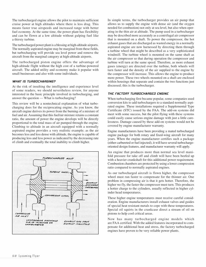
�8 L y c o m i n g F l y e r
The turbocharged engine allows the pilot to maintain sufficient cruise power at high altitudes where there is less drag. This means faster true airspeeds and increased range with better fuel economy. At the same time, the power plant has flexibility and can be flown at a low altitude without gulping fuel like a thirsty turbine.
The turbocharged power plant is a blessing at high-altitude airports. The normally aspirated engine may be marginal from these fields, but turbocharging will provide sea level power and remove the aircraft from the marginal category at high-altitude airports.
The turbocharged piston engine offers the advantage of high-altitude flight without the high cost of a turbine-powered aircraft. The added utility and economy make it popular with small businesses and also with some individuals.
WHAT IS TURBOCHARGING?
At the risk of insulting the intelligence and experience level of some readers, we should nevertheless review, for anyone interested in the basic principle involved in turbocharging, and answer the question — What is turbocharging?
This review will be a nontechnical explanation of what turbo-charging does for the reciprocating engine. As you know, the aircraft engine derives its power from the burning of a mixture of fuel and air. Assuming that this fuel/air mixture retains a constant ratio, the amount of power the engine develops will be directly proportional to the total mass of air pumped through the engine. Climbing to altitude in an aircraft equipped with a normally aspirated engine provides a very realistic example; as the air becomes less and less dense with altitude, the engine is capable of producing less and less power as indicated by the decreasing rate of climb and eventually the total inability to climb higher.
In simple terms, the turbocharger provides an air pump that allows us to supply the engine with dense air (and the oxygen needed for combustion) not only at sea level, but also when oper-ating in the thin air at altitude. The pump used in a turbocharger may be described more accurately as a centrifugal air compressor that is mounted on a shaft. To power the compressor, the hot exhaust gases that are discharged as wasted energy in a normally aspirated engine are now harnessed by directing them through a turbine wheel that might be described as a very sophisticated windmill. The turbine wheel is mounted on the same shaft as the air compressor so that during operation the compressor and turbine will turn at the same speed. Therefore, as more exhaust gases (energy) are directed over the turbine, both wheels will turn faster and the density of the air supplied to the engine by the compressor will increase. This allows the engine to produce more power. These two wheels mounted on a shaft are enclosed within housings that separate and contain the two functions just discussed; this is the turbocharger.
THE FACTORY TURBOCHARGED ENGINE
When turbocharging first became popular, some companies used conversion kits to add turbochargers to a standard normally aspi-rated engine. These installations required a Supplemental Type Certificate (STC) issued by the FAA. The add-on systems did meet with some success, but the pilot flying with these systems could easily cause serious engine damage with just a little care-lessness. Damage caused by these add-on systems would not be covered by engine manufacturer warranty.
Engine manufacturers have been providing a mated turbocharged engine package for both rotary and fixed-wing aircraft for many years. When the engine manufacturer certifies such a package (either carbureted or fuel injected), it will have several turbocharge-oriented design features, and manufacturer warranty will apply.
An engine that produces more than normal sea level mani-fold pressure for take off and climb will have been beefed up with a heavier crankshaft for this additional power requirement. Combustion chambers are protected by using a lower compression ratio compared to normally aspirated engines.
As our turbocharged aircraft is flown higher, the compressor wheel must run faster to compensate for the thinner air. One problem in compressing air is that it gets hotter. Therefore, the higher we fly, the faster the compressor must turn. This produces a hotter charge to the cylinders, usually reflected in higher cyl-inder head temperatures.
These higher engine temperatures must receive careful consid-eration. Engine manufacturers install exhaust valves and guides of special heat resistant metals to cope with these temperatures. Special oil squirts in the crankcase direct a stream of oil on pistons to help cool critical areas.
Now has many turbocharged engine models which are FAA certified. With the added features incorporated to com-pensate for additional heat and stress, the factory turbocharged engines have proven to be very reliable power plants.
L y c o m i n g F l y e r �9
CONTROLLING TURBOCHARGER SPEED
Turbochargers in use today may run at speeds up to 110,000 RPM.
Since the speed at which a turbocharger must operate is dependent upon the power desired from the engine and the density of the air at the altitude at which the aircraft is flying, it is necessary to provide the pilot with the capability of adjusting turbocharger speed. This is accomplished by controlling the amount of exhaust gas that is directed to the turbine side of the turbocharger. In those cases where air of increased density is not needed from the turbo-charger (low altitude or low power required), a wastegate in the exhaust system is allowed to remain open, and the exhaust gas is vented around the turbine wheel and through the wastegate to the atmosphere, very much like the normally aspirated engine. As the demand for dense air increases, the wastegate can be closed to a position that will force the proper amount of exhaust gas into the turbine and therefore speed up the compressor to meet the cur-rent demand for denser air. Adjusting turbocharger speed to meet changing power requirements is a matter of providing necessary controls over the wastegate, and therefore the flow of exhaust gas.
AUTOMATIC VS. MANUAL CONTROLS
Control of the wastegate for factory-installed turbochargers is accomplished by two basic methods. These are manual control or automatic control. Manual control is also divided into two types; the fixed-bleed system and the throttle/wastegate interconnect.
Those engines utilizing manual control over the wastegate require much more pilot attention than installations with automatic control. Pilot workload is reduced with a turbocharger that utilizes an automatically controlled wastegate unit.
The automatic controller adjusts for temperature or pressure or both, depending on the various applications, and permits the turbocharger to be controlled by normal throttle movements. The automatic control feature is normally set at the factory and should not be tampered with in the field.
OPERATION
Both the mechanic and the pilot must know how to operate the specific turbocharged system he works on or flies, so this infor-mation is not intended as a substitute for the Engine Operator’s Manual or the Pilot’s Operating Handbook. The treatment here is more general. But we can augment those basic references with explanations from the pilot’s point of view.
The most practical consideration of operation is to treat the auto-matic and manual systems separately. However, before we do that, there are a few basic handling or operational requirements that apply to both systems.
1. The throttle or throttles must be operated smoothly or the engines will surge, which is hard on the turbocharger and the engine. Those pilots trying a turbocharged installation for the first time should be aware of throttle sensitivity and the need for very smooth throttle movements. In case of the manual systems, the turbocharger requires time to follow throttle movement since it may operate at speeds up to 110,000 RPM. The automatic control systems experience this same phenomena and, in addi-
tion, all elements of the control system must stabilize following any movement of the throttle. Good advice is “Move the throttle controls slowly and wait.”
2. This advice is also good when leaning the mixture since the mixture setting has a great effect on engine operating tempera-tures. The operating temperatures of a turbocharged engine will be somewhat higher than those of a similar normally aspirated engine because the intake air is heated as it is compressed; this is particularly true at higher altitudes where the compressor must work very hard to supply dense air to the engine. Cylinder head temperatures may average 30˚ F higher at altitude, and smooth, steady operation of the mixture control will ensure that turbine inlet temperature (TIT) limitations are not exceeded.
3. Power sequence is very important with the turbocharged engine.
To increase power — Enrich mixture, increase RPM, then MP
To decrease power — Decrease MP, then RPM
4. High-altitude flights mean higher turbine speeds and hotter cylinder head temperatures. Observe these temperatures, and stay within the limits prescribed for best engine life.
5. Cruise control at altitude is in accordance with the specific instructions in the airplane Pilot’s Operating Handbook.
6. Turbocharged power plants require 100 octane aviation grade fuel as a minimum.
THE MANUALLY CONTROLLED TURBOCHARGER
The simplest form of manual control is the fixed-bleed system. It does not incorporate a wastegate, but allows some exhaust gas to continuously escape through an orifice of predetermined size. Size of the orifice establishes the critical altitude of the engine. The remainder of the exhaust gas is used to turn the turbocharger mechanism anytime the engine is running. In this system, engine power is adjusted by the position of the throttle plate in the carburetor or fuel injector, and the amount of exhaust gas available to turn the turbocharger is a result of the power developed at any particular throttle setting.
Lycoming developed a second manual system to be used primarily in single-engine installations. The throttle/wastegate interconnect system uses positioning of the cockpit throttle control to actuate both the throttle plate and the turbocharger wastegate. The design of this mechanism causes a programmed movement of the throttle plate and wastegate; the throttle plate starts to move toward the full-open position before movement of the wastegate affects any change in the exhaust bleed which will cause turbocharger speed to increase. At the fully advanced position of the throttle control, the throttle plate is at full open and the wastegate is closed to its maximum design limit.
A pressure relief valve is normally included in the factory developed system of each manually controlled turbocharger installation. The purpose of this valve is protection of the engine in case of inadvertent excessive throttle opening (overboost) by the pilot. With a manually controlled turbocharger system, the pilot is the controller, and must limit throttle movement to keep manifold pressure within the limit specified for the engine.
�0 L y c o m i n g F l y e r
The pilot should carefully read the Pilot’s Operating Handbook on this equipment, and also get a good checkout by a competent pilot qualified in the aircraft. Pilot technique cautions against sudden movements of the throttle, and recommends instead slow deliberate movements. For takeoff, this requires very smooth application of the throttle until manifold pressure indicates about two inches below the maximum for which the engine is rated. As the turbocharger speed builds up, the manifold pressure will increase slightly to the maximum limit. During climb at a fixed-throttle condition, manifold pressure will decrease at the rate of approximately one inch for each thousand feet. As engine power deteriorates, the pilot slowly advances the throttle to maintain the desired manifold pressure until the full-throttle position is reached at the critical altitude.
The pilot should be alert to the reaction of the manifold pressure in this type of engine when leaning at cruise power. At a fixed RPM and throttle setting, the manifold pressure will increase as the mixture is leaned to Best Power, and decrease when further leaned to Best Economy. The recommended procedure is that at the completion of the leaning procedure, if the manifold pres-sure is more than one inch from the beginning MP value, it is recommended that the mixture be returned to full rich and the MP adjusted accordingly so that the leaning procedure produces the desired manifold pressure.
THE AUTOMATICALLY CONTROLLED SYSTEMS
Owners of engines that call for more than field-level manifold pressure to produce rated power should know that the turbo-charger is operating at all times when the engine is running. These engines usually have turbochargers that are controlled by automatic systems.
The automatic systems used to control turbocharger operation utilize devices that sense differences of air pressure at var-ious points in the induction system, and utilize any changes to adjust the oil pressure that controls the position of the wastegate. Not all of these systems are exactly the same and, therefore, it is very important that the pilot understand exactly what manifold pressures to expect when full throttle is applied for takeoff.
Engines such as the Lycoming TIO-541 and TIGO-541 have controller systems that are set to provide red-line manifold pres-sures when the throttle is full open for takeoff. Other engines, many of those in the Lycoming TIO-540 series, utilize a density controller that will maintain a set power output at full throttle regardless of variations in altitude and in temperatures above or below standard; as a result, manifold pressures at full throttle may indicate several inches above or below that specified for standard day conditions.
Although the systems with controllers automatically protect against overboost at all normal RPM and MP settings, it is pos-sible to overboost a turbocharged engine nevertheless. Any sudden straight-arming of the throttles, particularly on cold engines, can cause an overboost condition that would exceed the red-line. But overboost can also take place even though the red-line MP has not been exceeded. This occurs where the pilot may have a low RPM and very high MP. An example of this has been observed when the pilot has let down with low RPM, then on the final approach
executed a go-around without first advancing RPM. Thus he could be pulling maximum manifold pressure (to red-line) at low RPM. This would produce a definite overboost condition, with resulting heavy detonation and undesirable compressor surge.
The engine manufacturers have service bulletins and service instructions for reference if this should happen. A severe over-boost could require a major overhaul of the engine and replace-ment of the crankshaft.
Of course, the nice feature of the automatic system for the busy pilot during climb is that once the throttles are set, there is a minimum of adjustment required. Cruise handling is similar to the other systems described earlier. During letdown, there is no worry about high MP because the pilot merely retards his throttles, and the automatic system does the work for him.
Since the turbocharger is operating during takeoff, all takeoffs at any altitude require full-rich mixture because the turbocharger provides full-rated horsepower, and full-rich mixture is required for that amount of power.
MAINTENANCE
Maintenance for all the turbo systems covered here is rela-tively simple. The daily preflight merely calls for a visual inspection prior to the first flight. Look at turbo mountings and connections for security, lubricant leakage or air leakage. There are the usual 50- and 100-hour inspections that are brief in what they recommend. Mechanics should not tinker with the system unless they have been specifically schooled. A very important requirement is the necessity to avoid dropping any loose items in the induction system. They will be sucked up and go through the turbine wheel damaging it and also possibly damaging the engine as well. This could become very costly.
Any overboosting should be entered in the logbook by the pilot. The mechanic must then refer to the manufacturer’s service publication for the necessary action to take. When the engine is exchanged or overhauled, the turbocharger should also be exchanged or overhauled.
SUMMARY
Turbocharging the flat-opposed cylinder piston engine was an innovation that improved and expanded the utility of the General Aviation airplane. Combining cabin pressurization and engine turbocharging from the same compressor included as part of the engine package, provides simplicity, which leads to low cost and light weight. The turbocharged piston engine had a great impact on the helicopter industry, particularly for use in mountainous areas. Altitude test flights and field experi-ence have indicated excellent fuel economy and range with the accompanying higher true airspeeds.
The turbocharger has been quite compatible with Lycoming piston engines. We have tried to give information on all aspects of turbocharging in an effort to aid pilot understanding of the subject. There is no substitute for a good checkout by an experienced pilot; and for specific knowledge about your aircraft, be sure to read the airplane Pilot’s Operating Handbook. Give the power plant and turbo the maintenance
L y c o m i n g F l y e r � �
they require and the careful operation they deserve, and they will give you performance with a long and satisfactory life.
Airline deregulation has caused changes. Many aircraft powered by Lycoming reciprocating engines are being used in the com-muter market. These aircraft operate under Part 135 of the Federal Air Regulations and generally have a regular schedule which must be maintained day after day. The engines of these aircraft, like those operated for individual or corporate transportation, are expected to reach the manufacturer’s recommended TBO when operated and maintained as specified in the Pilot’s Operating Handbook (POH) and appropriate maintenance publications.
Many commercial operators have requested assistance and advice on the subject of operating and maintaining their engines in a manner that will assist in meeting regular schedules and achieving recommended engine TBO. In response to these requests, a series of operating tips has been developed to emphasize that a slightly more conservative and cautious mode of operation will help to increase expected engine life. These tips are directed specifically at TI0-540-J series engines, but they may be applied to other Lycoming engines as well.
Individual or corporate operators may also find these tips beneficial for ensuring long, reliable engine operational life. Considering this, it seems appropriate to print these suggested operating tips for the benefit of all Lycoming TIO-540-J series engine owners and operators. These tips are applicable where maximum engine service life rather than maximum aircraft performance is the primary consideration.
“Tips from Fred” were outlined in a memo which is reprinted below:
�. INTRODUCTION:
This memo was originally directed at Part 135 Commuter usage, but any operator of Lycoming turbocharged engines where long engine service life is a major consideration may benefit. Power settings and procedures within the normal range, but more conservative than the maximum allowable limits specified in the Pilot’s Operating Handbook (POH), may be helpful in achieving this extended engine life. The following suggestions deal with the engine areas that lead to the necessity of overhaul by attempting to minimize wear rates and potential cylinder prob-lems, and to maximize turbo system and wastegate life through changes in operational procedures. Economic or performance considerations may require deviation from ideal recommendations with the possible attending loss of some of the maximum possible engine service life.
�. GROUND OPERATION:
a. In extremely cold weather (20˚ F and colder), engine and/or oil preheating should be utilized to minimize acceler-ated cold wear rates during the engine warm-up period.
b. Avoid rapid acceleration after any cold start-up, and make every effort to maintain a constant speed of about 1000 RPM for several minutes during the initial warm-up period.
c. Adhere to the lubricating oil recommendations for the average ambient air temperature, as listed in the latest revi-sion of Lycoming Service Instruction No. 1014. Note that SAE 15W-50 or 20W-50 all-temperature oil (MIL-L-22851 Spec) is approved for use in TI0-540 series engines.
d. Oil temperature indications should register on the aircraft gage before takeoff is attempted so that problems associated with unusually high oil pressure will be minimized.
e. All power settings must always be accomplished slowly and smoothly to minimize possible damage to the crankshaft dynamic counterweight system.
f. Taxi at the minimum power setting required to get the job done.
�. TAKEOFF:
a. Part throttle takeoffs should be avoided. The fuel injector metering jet is a two-hole unit, which is interconnected with the throttle. The secondary jet is fully opened only at full-throttle conditions. The richer fuel flow supplements engine cooling and deters engine damaging detonation. The turbocharger control system automatically seeks to maintain a constant density air charge at the fuel injector entrance. The density controller setting should be checked routinely with a temperature probe in accordance with Lycoming Curve Number 13225-C, as described in detail in the latest revision of Lycoming Service Instruction No. 1187. It is normal for the takeoff manifold pressure level to vary sig-nificantly as daily ambient ground level temperature changes. Never attempt to set rated manifold pressure based upon ambient temperature comparison and interpolation with the various rated power levels shown on Lycoming Curve Number 3216-C. That curve is intended only as an explanatory curve and should not be used for setting manifold pressure at rated conditions below crit-ical altitude. Items such as a dirty air filter, alternate air door not completely shut, loose rag or similar foreign object blocking the air filter will affect the rated manifold pressure level. The correct density setting can only be obtained by monitoring compressor discharge temperature and manifold pressure simultaneously.
b. The RPM should be at 2575 RPM for takeoff, and a full-rich mixture must be utilized.
�. CLIMB:
Climb should be accomplished with engine cooling in mind. Cowl flaps should always be open for climb. A higher than normal climb speed of 140 MPH is recommended to aid cooling. Maximum normal operating power of 2400 RPM, 40" Hg manifold pressure with partial leaning, in accordance with the POH, is permissible where terrain or conditions permit. A conservative climb power setting of 2400 RPM, 35" Hg manifold pressure is also recom-mended while maintaining cylinder head temperature as cool as 400˚ F by manual leaning. For maximum engine service life, an exhaust gas temperature of 1,400˚ F should not be exceeded.
�� L y c o m i n g F l y e r
�. CRUISE:
Conservative cruise power settings will also increase engine service life. A power setting of 2200 RPM and 31" Hg mani-fold pressure is recommended for all cruise flight. A maximum 1,450˚ F exhaust gas temperature and maximum cylinder head temperature of 420˚ F is recommended. Slight enrichment or cowl flap opening should be utilized if the cylinder head temperature level cannot be maintained. The preceding conditions correspond to a power setting of about 63% at standard conditions and approximately best power mixture strength. It may be necessary to increase the cruise manifold pressure setting on a hot day and to decrease the cruise manifold pressure on a cold day. As a rule of thumb, modify manifold pressure by 1% for each 10˚ F variation from standard altitude conditions. Note that this cruise power setting is not recommended for new engines or engines in service following cylinder replacement or top overhaul of one or more cylinders. Under those circumstances, to assure the proper ring seating, cruise should be at 65% to 75% power for the first 50 hours of operation, or until oil consumption has stabilized.
�. DESCENT:
Rapid cooldown during initial descent can damage the engine. Gradual cooldown is preferable. The descent power reduction should be accomplished in several steps. Ideally, the descent should begin by nosing the aircraft over slightly while engine power and mixture remain at the cruise set-ting. The added speed will initiate a gradual cooldown. When the CHT has stabilized, reduce the manifold pressure to 25" Hg, and relean the mixture to maintain 1,350˚ F exhaust gas temperature, which will prevent rapid cooldown. After a period of at least one minute, a further reduction of man-ifold pressure to 20" Hg and 2000 RPM can be made, if necessary. Again, mixture should be leaned to maintain 1,350˚ F exhaust gas temperature. Cowl flaps should not be used as an aid in slowing the aircraft during descent. Descent power settings at greater than 20" Hg manifold pressure should be utilized for the greatest possible time to avoid accelerated piston ring wear.
�. LANDING:
a. Following landing, the minimum necessary taxi power will aid in engine cooldown. Extending the ground-idle cooling period reduces turbocharger temperature and reduces the tendency of turbo coking following hot engine shutdown. Ideally, a five-minute minimum cooling period is desirable. Following landing, opting for the second turn-off can aid the cooldown.
b. Higher than required power settings for ground operation increase the possibility of dirt ingestion into the engine.
Some General Aviation pilots may not be aware of the number of detrimental influences on their aircraft engines which can be
identified as thieves of engine power, and how they can create unsafe flight conditions. As an example, in most instances, the moderate engine power loss that occurs from attempting a takeoff at sea level where a pilot has inadvertently left the carburetor heat in full-hot position from the previous landing may cause a scare but not necessarily an accident. But move the situation to a 5,000 feet or higher (density altitude) small airport, again forget there is full carburetor heat, add a rich carburetor condition, and the sum total of these combined power thieves add up to a takeoff or go-around accident. Similarly, a review of accidents over the years shows that in most cases it has rarely been one factor responsible for a crash, but rather one small item, added to another small item, added to a third; all of these small items finally add up to a total beyond the ability of the pilot to cope. This is how accidents happen. So let’s identify several of these power thieves in an effort to make flight as safe as we can.
PREVENT POWER LOSS ON TAKEOFF WITH DIRECT-DRIVE ENGINES IN COLD WEATHER
In cool or cold weather, pilots should take extra care prior to attempting to takeoff with a cold engine and cold oil, and thereby prevent a temporary power loss during a critical part of the takeoff. Cold or heavy oil can and quite often does affect normal operation of the hydraulic lifters. Remember that aviation lubri-cants are heavier when cold than the commonly used automotive engine oils and require a little more time in warm-up to obtain normal flow in order to function properly throughout the air-cooled aircraft engine.
To prevent possible power loss, a proper warm-up should be con-ducted. The engine is usually warm enough for pre-flight ground check in above-freezing temperatures after 2 to 3 minutes running at 1000 to 1200 RPM. Below freezing temperatures, the warm-up period should be longer. With turbocharged power plants, cold oil and cold engines require a longer warm-up period to assure proper controller operation and to prevent manifold pressure overboost.
After the above recommended warm-up period in cool or cold weather, including magneto and runup check, if the oil pressure is consistently over maximum red-line, have a knowledgeable mechanic adjust oil pressure so that it does not exceed red-line at takeoff or climb powers, and yet it is within the recommended green arc area at cruise. Cold weather usually requires a longer warm-up period.
Another cause of power loss under these temperature and flight conditions has been the use of a heavier-weight viscosity of oil than recommended for the ambient temperature flight condition. A heavier-weight oil than recommended in cool or cold weather will help prevent the normal operation of the hydraulic lifters and thereby cause a loss of power.
Thus, to prevent power loss on takeoff with direct-drive engines, select the proper weight of oil for your engine for cold weather operation Make a careful run-up prior to takeoff with cold oil and a cold engine and observe engine instruments. Extend your warm-up period in cold weather until oil pressure is within rec-ommended limits, or consult a mechanic concerning a compro-mise adjustment. If in doubt about power output, a brief smooth full-throttle check is recommended.
L y c o m i n g F l y e r ��
CARBURETOR HEAT OR ALTERNATE AIR HEAT AS POWER THIEVES
In the opening paragraph, carburetor heat was used as an example of a cause of power loss, but many pilots aren’t sure they under-stand the reason for it. Flight tests conducted with a precision torque meter installed have measured fairly accurately a loss of as much as 15% of engine power when full alternate air or carburetor heat have been applied. As a specific explanation, there is a small power loss when we use heat because the pilot has switched from the direct, colder ram air to an indirect carburetor heat muff, or a similar indirect source of warm air with an alternate warm air source from inside the cowling. This accounts for an average 3% power drop because of the loss of ram air. The major portion of the engine power loss is caused by the carburetor heat or alternate air heat. Aircraft engines are checked for their horsepower output at a corrected standard temperature of 59˚ F. Engineering has provided a simple rule of thumb for the effect of heat on power, i.e., for every 10˚ F of heat above the standard 59˚ F, there is a 1% power loss. Since the average heat source on an engine provides at least 100˚ F of heat above standard, this heat condition causes an average power loss of 10%. Our measurable total power loss at sea level with standard conditions is already up to 13%.
When warm air is used by the pilot, the mixture becomes richer, and the engine may roughen with another slight power loss as a result. In addition, the higher the altitude with its less-dense air, the greater the enriching effect because the fuel-metering device will become richer at altitude and the engine less efficient. Thus, there will be another small, difficult to measure, power loss to be added to the 13% loss already accumulated.
With full carburetor heat applied, most float-type carburetors react very sluggishly or inefficiently on a straight-arm throttle technique during a touch-and-go landing or an aborted landing. In some cases, the float-type carburetor may refuse to accept the throttle when it is applied in this manner. A gradual, steady application of the throttle is always the best approach.
We should also remind the pilot that when using carburetor heat or alternate air heat at cruise power, to adjust the mixture lean, otherwise the mixture will be rich. If the heat causes an undesir-able power loss at cruise, and there is throttle available, the pilot may bring the manifold pressure up at least to the power reading before application of heat; and if additional power is needed and available, add a maximum of two inches of MP, or 100 RPM (fixed-pitch prop) above the previous power, and then adjust the mixture. It is possible to compensate for the horsepower loss due to heat by means of the latter technique if throttle or RPM are available.
EFFECTS ON POWER AT A HIGH-ALTITUDE AIRPORT ON A HOT DAY
To fly safely at a high-altitude airport (5,000 ft. density alti-tude and above) on a warm weather day, we must consider the aerodynamic loss of efficiency on the airplane and propeller under these conditions, and the power loss effect on the engine. A good “rule of thumb” for the pilot to remember is — for each thousand feet above sea level, the takeoff run increases approximately 25%. In the case of normally aspirated engines (not turbocharged or supercharged), at an altitude of 10,000 feet, about one-half of available engine horsepower is lost.
We can create a practical flight problem for the pilot who is faced with a high-elevation field takeoff. At Denver, Colorado, where the field elevation indicated on the airplane altimeter is 5,000 ft., the pilot should consult the density altitude chart for takeoff and must know that the published performance cri-teria of an aircraft is generally based on standard atmospheric conditions (temperature 59˚ F, pressure 29.92" of mercury at sea level). In checking the density chart and applying the ambient temperature of a summer day of 80˚ F, the careful pilot will note that the density altitude is actually 7,500 feet, and the takeoff distance at this density altitude will be 2.3 times the sea level takeoff roll shown in the Pilot’s Operating Handbook.
The same pilot flying to Laramie, Wyoming, for the next landing and subsequent takeoff, might meet the following typical flight conditions.
The field elevation is 7,276 feet, and with an ambient temperature of 60˚ F, the actual density altitude will be 9,300 feet, with a takeoff roll 2.9 times the sea level takeoff. Furthermore, the pilot must remember — the higher the ambient temperature indicates, the higher the density altitude becomes. At this elevation, the pilot of normally aspirated aircraft engines should consider takeoffs in the cool temperatures of early morning or evening hours, rather than during the hot hours of the day.
Summing up the specific flight condition just discussed, the pilot must remember — when the temperature becomes higher than standard (59˚ F), the density of the air is reduced and aerodynamically affects overall airplane performance. The horsepower output of the engine is decreased because its fuel air mixture intake is reduced. The propeller develops less thrust because the blades are less efficient. The wings develop less lift because the less dense atmosphere exerts less force on the wings as airfoils. As a result, the takeoff distance is increased and the climb performance reduced.
In order to cope with high-elevation airport takeoffs with nor-mally aspirated engines, whenever the density altitude is 5,000 feet or higher, the pilot must compensate on the ground before takeoff. With a direct-drive engine and a fixed-pitch propeller, run the engine up to takeoff RPM and lean the mixture until a maximum RPM is noted; leave mixture at that position and accomplish the takeoff. If the engine has a governor, run it up to takeoff RPM, and then lean until the engine smooths out and gives the indication of maximum power. At 5,000 ft. density altitude or higher, the available horsepower has been reduced so that leaning as described will not damage a healthy engine. If an EGT system is available, lean to +100˚ F on the rich side of peak EGT on a direct-drive normally aspirated Lycoming engine.
All turbocharged or supercharged engines must use full rich for takeoff at any elevation airport. This includes either manually operated turbos or the automatic type.
IGNITION SYSTEM POWER ROBBERS
There are several possibilities whereby the ignition system can be the cause of power loss in the engine. There is a power loss of approximately 3% with a single dead magneto or running on one mag. In fixed-wing aircraft, if the pilot lost a magneto in flight
�� L y c o m i n g F l y e r
it might not be a serious situation to complete the flight safely provided other power robbers didn’t begin to add to the problem. But in the case of the rotary-wing aircraft, it could be serious during takeoff, hover, or landing because there are the regular inroads on power — such as operation of the tail rotor, the cooling fan, the alternator, the transmission and also power loss from any excessive rotor blade trim tab position beyond the manufacturer’s recommendation. Therefore, magneto maintenance really is a critical item on rotor-wing aircraft.
Other power loss influences in the ignition system include worn or fouled spark plugs that tend to provide a weak spark. Likewise, deteriorated magneto points will have some power loss influence. We have also learned the difficult way that old, worn or cracked (insulation) ignition harnesses can cause a loss of power, particu-larly at altitude. If this is suspected, it can be checked by means of a harness tester.
We know that magneto timing, either early or late, has a detrimental influence on power. Sound maintenance can eliminate these problems. But coming back to spark plugs, the correct plug is most important for efficient engine operation, and Lycoming Service Instruction 1042 is the official reference source. Maintenance must also be careful that long-reach plugs are used only in those cylinders designated by an area of yellow paint in the fin area between the spark plug and rocker box. Cylinders designed for short-reach plugs may be either gray, blue or unpainted in this area. If the wrong length plug is used in the cylinder, it will cause a loss of power and perhaps preignition or detonation.
Champion Spark Plug Company published a bulletin warning that one dirty harness terminal (cigarette) or contaminated plug barrel can rob an aircraft engine of two horsepower during takeoff. When dirt and moisture are allowed to accumulate on the cigarette or spark plug barrel insulator, connector well flashover can occur resulting in plug misfire. The high-voltage current will take the easy path to ground rather than spark between the firing-end electrode gap. Cigarettes, harness terminals, seals and spark plug barrels should be kept clean and dry. When ciga-rettes are clean, do not touch them as the moisture on fingers is enough to contaminate them again. Replacing these parts and pieces at reasonable periods is inexpensive insurance against power thieves. When the latter are at work, sharp performance and economy are lost.
INDUCTION SYSTEM LEAKS
If the intake pipes are loose at either end, leakage that leans the mixture will take place and cause a power loss. It could be critical in the takeoff or climb power ranges. In most engines, the leakage can be detected by observing fuel dye evidence at the leakage area. Any time this condition is discovered, it must be remedied before the aircraft is flown again.
In those engines using a carburetor, we have observed power loss effects from worn air boxes where the carburetor heat flapper valve in the air box remains partly open. When the outside air temperature is above 59˚ F, this malfunction can create a sneaky power loss, particularly at higher than cruise power.
BLOW-BY AND COMPRESSION LOSS
Another power loss condition is that of blow-by — or oil blowing by the piston rings and getting into the combustion chamber in more than desirable amounts. It occurs with broken or worn piston rings, scored cylinder walls and bell-mouthed exhaust valve guides. Oil in the combustion chamber fouls spark plugs and reduces their efficiency. It also lowers the octane rating of the fuel and causes a loss of power, particularly at takeoff or climb. If the engine is not close to its normal overhaul life, then a top overhaul would be in order if more than one cylinder showed this condition.
Power loss from valve leakage may not be noticeable to the pilot while in flight. If an exhaust valve becomes burned and deteriorated at the edge of the head, it may cause an engine miss in flight. But leaking intake valves are difficult to detect during flight. The latter either get irregularly seated and cause a compression loss, or they can also cause a loss if they get tuliped from preignition. A good differential compression check will pick up most of these discrepancies except for some occasions of broken rings. However, any oil in the combustion chamber from broken rings would, in addition, call for a visual inspection with a borescope or a gooseneck light.
SUMMARY:
We can’t list all the many power-robbing factors here, but we have tried to list the important ones, along with recommendations on how to cope with them. Again, we want to remind all concerned of the dangerous difference between an engine problem where both spark plugs fail to fire in a cylinder, which is immediately obvious, as compared with the small power loss problem that is not as obvious. The power thieves take power away in small quantities per cylinder until several of them happen to occur at the same time, reaching serious proportions and a definite unsafe flight condition. Be aware — don’t become a victim of power thieves!
The FAA has published a pamphlet entitled “Wet Air” that enlightens the pilot concerning this potential danger to engine power. Scientists state that we can dismiss any appreciable effect of dampness in the air on the efficiency of the wing in lifting and the propeller in thrusting. But they say the effect of water vapor or high humidity on engine power output can be significant, and should be taken into consideration when planning takeoffs in muggy or highly humid weather.
The pamphlet explains the power loss by pointing out that with water vapor present, there is less air entering the engine. Secondly, this creates an excessive enrichment because the fuel amount is the same, but the amount of air is less. Furthermore, the water vapor slows the burning which slightly affects power, but offers no cooling value to the engine.
FAA recommends a rough rule of thumb is to keep high-moisture content in mind, and suggests the pilot consult his Pilot’s Operator Handbook for takeoff distances, and add another 10% for the possible
L y c o m i n g F l y e r ��
effects of engine power loss due to water vapor on a muggy day. The pilot can easily identify a high water vapor condition by the muggy, hot, sticky feeling in this kind of weather. The higher the ambient temperature, the greater the water vapor content in the air, i.e., at 96˚ F, the water vapor content will be eight times as great as at 42˚ F. The write-up also states that the effect of water vapor on supercharged, fuel-injected piston engines is substantially the same as the effect on other piston engines. “Fuel-injection systems meter fuel on the basis of a given volume of gas entering the combustion chamber, whether the gas is air or water vapor, just as the carburetor does. It cannot discriminate between combustibles and noncombustibles.”
Pilots should be alert to the effect of wet air on the performance of their engine.
We have firm evidence that engines not flown frequently may not achieve the normal expected overhaul life. Engines flown only occasionally deteriorate much more rapidly than those that fly consistently. Pilots have asked, “What really happens to an engine when it’s flown only one or two times per month?” An aircraft engine flown this infrequently usually accumulates rust and corrosion internally. This rust and corrosion is often found when an engine is torn down. Some operators are running the engines on the ground in an attempt to prevent rust between infrequent flights. This may harm rather than help the engine if the oil temperature is not brought up to approximately 165˚ F, because water and acids from combustion will accumulate in the engine oil. The one best way to get oil temperature to 165˚ F is to fly the aircraft. During flight, the oil normally gets hot enough to vaporize the water and most acids and eliminate them from the oil. If the engine is merely ground run, the water accumulated in the oil will gradually turn to acid, which is also undesirable. Prolonged ground running in an attempt to bring oil temperature up is not recommended because of inadequate cooling that may result in hot spots in the cylinders, baked and deteriorated ignition harness and brittle oil seals which cause oil leaks. Pulling on engine through by hand if it has not been run for a week or more is NOT recommended, and can result in increased wear. Refer to Lycoming Service Letter L180. If the engine is flown so infrequently that it does not accumulate the operating hours recommended for an oil change (25 hours for a pressure-screen system and 50 hours for a full-flow filter system), then the oil should be changed at four-month intervals to eliminate water and acids.
Tale Number One — “The most likely time for an engine failure to occur is at the first power reduction after take-off.”
Every individual who pilots an aircraft has probably heard this
statement at some time. Is it a true statement? We will venture a guess and say that perhaps it may have been at some time in the distant past.
Several years ago, this question was asked of me and it led to questioning some FAA employees and a number of other pilots about where the justification for this statement might be found. After several weeks of poking into this subject, it was finally necessary to conclude that we could find no justification — that it was simply an “Old Wives’ Tale.”
A letter which recently came from a Flyer reader takes this one step further. First, it appears that there are many who continue to repeat this tale. This caused our reader to delve into the subject a little deeper — perhaps a little more scientifically than I did. Our reader studied a computer readout which had data on incidents of engine failure over a recent three-year period. Based on the material in that report, this reader concluded that engine failures during takeoff are quite rare, and that failures during cruise are far more common. This does seem logical since the engines of fixed-wing aircraft run a majority of their operating life in the cruise-power range.
Our reader also had a very believable theory about how this tale may have gotten started. He wrote, “It seems likely to me that this idea got started when twin-engine flight instructors would simulate an engine out during takeoff — right about the time the student put his hand on the prop control to reduce power. Gradually, the idea was propagated that this was the most likely time for an engine failure, when in reality it was a likely time for an instructor to simulate a failure.”
From these two searches for justification — with none being found in either case, I believe it is fair to conclude that “the idea of an engine failure being most likely to occur at the first power reduction after takeoff” is, in fact, an old wives’ tale. For the sake of safety, lets stop repeating this false tale and start promoting the idea that we should be ready to deal with power failure at any time.
A second old wives’ tale is still being promoted by some indi-viduals. This tale involves the constant-speed propeller and goes like this: “The RPM in hundreds should not be exceeded by the manifold pressure in inches of mercury.” Referred to as a “squared power setting” (i.e., 2400 RPM x 24" of MP), it appears that this tale may be the result of a carryover from some models of the old radial engines which were vulnerable to bearing wear at high power settings. Changes in engine design, along with improved metals and lubricants, permit changes in the operation of modern flat, opposed-cylinder power plants.
Any pilot who believes that squared power settings continue to be necessary should be urged to read and understand the information in the Pilot’s Operating Handbook (POH). While there are limits to the power which should be taken from most engines, particu-larly those which are turbocharged, the combinations of RPM and MP listed in the power charts of the POH have been flight tested and approved by the airframe and power plant engineers. For example, if the POH chart lists 2200 RPM and 26" of MP as an approved power setting, pilots should not be apprehensive about using that setting if it meets their needs.
�� L y c o m i n g F l y e r
Isn’t it strange that some bits of information come to be believed by large segments of a population even when they are untrue? The two issues discussed above are good examples. Will it ever be possible to get all of our fellow pilots to reject the two false ideas outlined here? Let’s keep trying.
Spark plug fouling in your aircraft engine may be a problem. Lycoming Service Letter L192 provides information that may be very helpful in reducing spark plug fouling. To aid our readers, the entire text of the latest revision to Service Letter L192 is printed here:
“In many cases, spark plug fouling resulting from the tetraethyl lead (TEL) in aviation fuels can be reduced or eliminated by proper operating techniques.
“The problem of lead fouling arises when low engine-operating temperatures coupled with a rich mixture prevent the complete vaporization of the TEL. Under these conditions, lead deposits can form in the spark plug electrodes, causing misfiring. By establishing and maintaining proper engine-operating tempera-tures, the TEL can be kept properly vaporized and pass out the exhaust system.
“However, the Champion Spark Plug Company has designed a spark plug which will reduce or eliminate the effects of lead fouling. The spark plug REM-37-BY can be used in the following engines: O-235; O-320; IO-320-B, -F, AIO-320; LIO-320-B; IO-320-A, -D, -E; AEIO-320; HIO-360-B; HO-360; O-360-A, -C, -E, -F; IO-360-B, -E, -F; AEIO-360-B, -H; O-360-B, -D; IVO-360; VO-360-A, B.
“For operators experiencing lead fouling, the following operating recommendations are made:
1. By use of the spark plug recommendation charts, be certain the proper plugs are installed. Do not simply replace the same part number of those removed. A previous mechanic may have installed the wrong plugs. Reference latest edition of Service Instruction No. 1042.
2. Rotate top and bottom spark plugs every 25 to 50 hours. Top plugs scavenge better than the bottom ones.
3. Proper adjustment of the idle speed (600 to 650 RPM) fuel mixture, and maintenance of the induction air system, will ensure smooth engine operation and eliminate excessively rich fuel/air mixtures at idle speeds. This will minimize the separation of the non-volatile components of the high-leaded aviation fuels greatly retarding the deposition rate.
4. The engine should be operated at engine speeds between 1000 and 1200 RPM after starting and during the initial warm-up period. Avoid prolonged closed-throttle, idle-engine speed opera-tion (when possible). At engine speeds from 1000 to 1200 RPM, the spark plug core temperatures are hot enough to activate the lead scavenging agents contained in the fuel which retards the formation of the lead salt deposits on the spark plugs and exhaust
valve stems. Avoid rapid engine-speed changes after start-up, and use only the power settings required to taxi.
5. After a flooded start, slowly run the engine to high power to burn off harmful lead deposits, then return the engine to normal power.
6. Keep engine operating temperatures in the normal operating range. Too many people think the lower the temperatures, the better. Keep cylinder head temperatures in normal operating range by use of normal power and proper leaning. Use oil cooler baffles to keep oil temperature up in winter.
7. Use normal recommended leaning techniques at cruise condi-tions regardless of altitude and relean the mixture with application of alternate air or carburetor heat. If aircraft is used as a trainer, schedule cross-country operation whenever possible.
8. Rapid engine cooldown from low-power altitude changes, low-power landing approach and/or engine shutdown too soon after landing or ground runs should be avoided.
9. Prior to engine shutdown, the engine speed should be main-tained between 1000 and 1200 RPM until the operating tem-peratures have stabilized. At this time, the engine speed should be increased to approximately 1800 RPM for 15 to 20 seconds, then reduced to 1000 to 1200 RPM and shut down immediately using the mixture control.”
Paul McBride, a former Lycoming employee widely known as “Mr. Lycoming,” likes to tell the story of the Mooney owner whose preowned Lycoming IO-360-powered single wouldn’t get up to the specified maximum RPM setting of 2700. After an adjustment at a shop, the engine did obtain 2700 RPM on the gage, but the power plant failed in flight shortly thereafter.
After a safe emergency landing, Canadian authorities took over and found that a connecting rod had failed. Contributing to the failure was a manifold pressure gage that was reading two inches low — not an unusual error, according to McBride — but more importantly, the tachometer that was reading 500 RPM too low. The error meant that the engine had been turning at 3200 RPM, a factor that ultimately led to the failure.
The point of McBride’s story is not to try to assign blame, but to accent the dangers of having blind faith in the accuracy of engine instruments. Many owners have such faith: McBride recalls seeing engines that had been overhauled three or more times, with owners reinstalling the original engine instruments each time. Lycoming “strongly” recommends getting engine instruments calibrated annually (see SI 1094D, Fuel Mixture Leaning Procedures, and SSP 400, Operating Recommendations for the TIO-540-AE2A engine). It’s important to note that engine gages are not considered part of the engine proper. In fact, FAA-
L y c o m i n g F l y e r ��
approved data covering the verification and calibration of the instrumentation is the responsibility of the airframe manufac-turer, not the engine maker.
In between overhauls, it’s up to the pilot in command or the maintenance shop to spot calibration errors. Aviation maintenance technicians, as part of a 100-hr. or annual inspection, should scan the gages for proper operation during a pre-inspection run-up. If there’s a problem, gages and/or sensor units would likely be swapped out or sent out to an avionics shop or repair facility for recalibration or fixes. Once the system is returned, Lycoming recommends that the gage, sensor and interconnect wiring be calibrated by a qualified technician or agency before flight.
Of the typical engine instruments — tachometers, oil tempera-ture gages, oil pressure gages, cylinder head temperature gages, exhaust gas temperature, manifold pressure gages and turbine inlet temperature probes for turbocharged engines — tachometers are the most notorious for being out of calibra-tion, says McBride. Calibration errors as small as 5% or 10% in RPM reading “will greatly increase the load on the propeller and the engine bearings during operation,” he says. Even off-the-shelf instruments are not beyond reproach. McBride says one maintenance facility owner told him that he’d once tested five tachometers off the shelf and found that each was indicating about 150 RPM low. That’s an error of more than 5% of the cruise RPM of many engines.
An instrument expert with Keystone Instruments in Lock Haven, Pennsylvania, says an installation error as innocuous as cutting a tachometer cable ¼-inch too long can cause the instru-ment to read 500 to 600 RPM fast; worse yet, using the wrong cable can damage the tach. Usually though, he says problems arise when the inside of the gage gets dirty and needs to be cleaned. Either way, operators are required to send gages to an authorized maintenance facility for repairs or recalibration, according to Keystone.
Figuring out whether gages are calibrated correctly in the field is sometimes obvious, sometimes not — a la the Mooney mishap. An oil temperature gage, for instance, should read the ambient temperature before the engine is started. Manifold pressure, too, should match the ambient pressure before start.
Some gages can be operationally verified on the cheap by a local maintenance shop. Ben Visser, an aviation columnist and former Shell Oil chemist, recommends checking oil temperature gages by placing the sending unit in a pan of oil sitting on a hot plate. Using a thermometer, Visser says to heat the oil to 180˚ F then to mark the gage with a permanent marker, regardless of whether the gage has temperatures printed on the face.
Why 180˚? Visser explains that the peak oil temperature in a normally aspirated engine is typically 50˚ F higher than the tem-perature of the oil in the sump, the location of the sensor. The peak temperature in a turbocharged engine is about 70 to 75˚ F hotter than the indicated temperature. He says the typical “green band” on an oil temperature gage ranges from 120˚ F to 245˚ F.
By calibrating the gage and operating near the 180˚ point in cruise, Visser says the oil temperature at the hottest point in the engine will exceed 212˚ F, boiling off any water that has accu-
mulated in the oil. By consistently operating below the boiling point, Visser says water and acid can build up in the crankcase, leading to rust and corrosion and reduced engine life. Keystone sometimes checks its oil temperature gages by immersing the sending units in boiling water to verify the gage reads 212˚ F.
The arrival of solid-state integrated avionics and liquid-crystal displays for the cockpit, while eliminating the ability to strike a line on a gage face, will undoubtedly boost reliability and read-ability of engine gages. Popular systems like Blue Mountain Avionics’ EFIS/One “glass” cockpit for experimental aircraft allows an operator to display as many as 16 different engine gages on-screen, whether the input from each is voltage, differ-ential voltage, resistance or thermocouple. Calibrating the unit is relatively simple, too — it has a special screen that allows the operator to view and modify the setup and calibration information for each sensor.
The flow of oil through a Lycoming reciprocating aircraft engine is known to be a necessary function during the operation of the engine. Pilots are often not at all concerned about how this func-tion occurs, as long as the oil pressure and oil temperature indica-tors show a proper reading. A & P mechanics, on the other hand, often need to know how the system works and what parts control the flow of oil during various phases of operation. Because of the large number of calls concerning this subject, which are received by Lycoming Service Specialists, we can be sure that there are many who do not have a good understanding of the oil system.
It is not surprising that many A & P mechanics do not have a firm grasp on the operation of the oil system. There is room for confusion since there are two basic systems and several variations on each of these.
Except for the screens, filter and oilcooler, the flow of oil through the engine is completely pre-determined by the designed engine-running clearances and by the passages which are drilled in the crankcase and accessory housing during engine manufac-ture. This flow of oil serves three purposes. First, it lubricates, but cooling the engine by carrying away the heat generated by combustion is a second purpose, which is often just as important. Many engines, particularly those which are turbocharged, have oil squirts in each cylinder which are designed to direct cooling oil on the back side of the piston. And finally, the oil cleans the engine by picking up dirt and depositing it in the screens or filter, or by keeping that dirt in suspension until the oil is changed.
The oil which has done its lubricating, cooling and cleaning flows by gravity back to the oil sump. From the sump, the oil pump pulls the oil through the suction screen. This screen will filter out large particles of carbon, dirt or metal. The pump then forces the oil through one of the two basic systems. In each of the two basic systems, there is a valve which forces the oil through the oil cooler when the valve is seated, or allows
�8 L y c o m i n g F l y e r
the oil to bypass the cooler when the valve is open. Lycoming engines were originally equipped with a bypass valve which was controlled by a spring. Referred to as a spring and plunger type, it functioned as a result of the amount of pressure in the oil system. The spring-controlled bypass system was superseded by a system controlled by a Thermostatic Oil Cooler Bypass which reacts to oil temperature changes.
Operation of the spring-controlled bypass system is the result of thick oil which causes an increase in differential pressure across the bypass valve and causes the bypass valve to be open, thus bypassing the oil cooler. As the oil warms up, oil viscosity and pressure in the system are reduced, allowing the bypass valve to close and forcing oil flow through the oil cooler. Although the bypass valve helps the engine to warm up more quickly by routing cold oil around the oil cooler, its primary function is for system safety; should the oil cooler become plugged for any reason, system pressure will rise and the differential pres-sure across the bypass valve will again cause the valve to open. This by-passes the oil cooler and prevents a possible rupture of the cooler and loss of the oil.
The Thermostatic Oil Cooler Bypass Valve was designed to provide better control of the engine oil temperature while also maintaining the safety of the oil system by bypassing oil around an oil cooler which is plugged for any reason. The thermostatic oil cooler bypass valve may be used on engines which use the pressure-screen system and on engines which have a full-flow oil filter. For most engine models, an oil filter also requires an oil filter adapter. While the oil is cold, this system allows oil to flow through the oil filter without passing through the oil cooler. As oil temperature rises to approximately 180˚ F, the valve closes and forces the oil to pass through the oil cooler. The oil then returns to the accessory housing where it is routed through the oil filter adapter, the filter and then again through the filter adapter, acces-sory housing and finally into the crankcase.
The oil filter is another part of the system where blockage could cause serious problems. For this reason, an oil filter bypass is built into the oil filter adapter, or in the case of engines utilizing a dual magneto, into the accessory housing. These bypass valves are built-in safety features which activate as a result of excessive pressure in the oil filter. The oil filter bypass is not adjustable.
Oil enters the crankcase of most Lycoming engines near the top of the right rear cylinder where it passes through the pressure-relief valve. There are three types of pressure-relief valve. With either the short or long dome valve, pressure is adjusted by removing the dome and adding or deleting washers which are located under the controlling spring. There is also a third style of pressure-relief valve which may be adjusted with the twist of a wrench or screwdriver.
An individual looking for the pressure-screen housing may not find exactly what he or she is looking for since there are two
possible variations. The housing for the pressure screen may have one hole facing the rear of the engine. This housing is used on engines incorporating a spring and plunger to control oil flow, and the single hole will be used for oil temperature probe. Another style of pressure-screen housing has two holes facing the rear of the engine. The small hole is used for oil temperature bulb connection, and a Thermostatic Oil Cooler Bypass Valve is installed in the large hole.
Even more attention to detail may be required when an oil filter is installed. The pressure-screen housing must be removed and oil-filter adapter installed in its place. With the oil-filter adapter installed, either a spring-controlled bypass valve installed in the accessory housing just above the adapter, or a thermostatic bypass valve installed in the bottom of the adapter may be used to control oil flow to the oil cooler. Because of the better oil-temperature control, use of the thermostatic oil cooler bypass valve is preferred by Lycoming. For engines shipped from the fac-tory with an oil filter, and requiring an oil cooler in the aircraft installation, it is standard procedure for Lycoming to supply a thermostatic bypass valve. The hole in the accessory housing which is provided for a spring-controlled bypass valve is capped with a plug. A hole on the top of the adapter is provided for the oil temperature bulb.
A possible variation to the flow of oil which may be found with a Lycoming engine. Some airframe manufacturers have utilized small engine models without an oil cooler. At the request of these airframe manufacturers, these engines are not machined to accommodate an oil cooler. Individuals who acquire these engines for use in their home-built aircraft may need an oil cooler to keep temperatures within operating limits. This can be accomplished by utilizing an adapter – Lycoming part number 62418. Utilization of this adapter will allow the engine to be used and the oil to be cooled, but there are limita-tions. An oil filter cannot be installed, and only the one-hole pressure-screen housing can be used. This limits the system to use as a spring-controlled oil cooler bypass valve which is installed in the adapter.
There are several bits of information which may be helpful to those who have now acquired a better understanding of the Lycoming engine oil system. Lycoming Service Instruction 1008B gives instructions for installation of a Thermostatic Oil Cooler Bypass Valve on engines which have a pressure-screen housing and no filter. Special Service Publication (SSP) 885-2 gives instruction for the installation of engine-mounted oil filter kits. And finally, a kit (Number 05K21437) for a remotely mounted oil filter has been developed.
The Service Specialists at the Lycoming factory receive many calls about the oil system and its many possible variations. The material presented here is intended to help answer many of those questions.
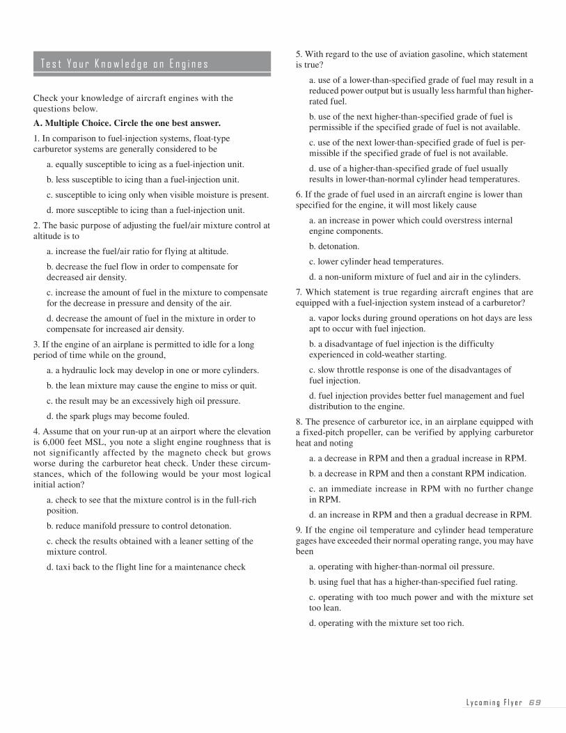
L y c o m i n g F l y e r �9
Check your knowledge of aircraft engines with the questions below.
A. Multiple Choice. Circle the one best answer.
1. In comparison to fuel-injection systems, float-type carburetor systems are generally considered to be
a. equally susceptible to icing as a fuel-injection unit.
b. less susceptible to icing than a fuel-injection unit.
c. susceptible to icing only when visible moisture is present.
d. more susceptible to icing than a fuel-injection unit.
2. The basic purpose of adjusting the fuel/air mixture control at altitude is to
a. increase the fuel/air ratio for flying at altitude.
b. decrease the fuel flow in order to compensate for decreased air density.
c. increase the amount of fuel in the mixture to compensate for the decrease in pressure and density of the air.
d. decrease the amount of fuel in the mixture in order to compensate for increased air density.
3. If the engine of an airplane is permitted to idle for a long period of time while on the ground,
a. a hydraulic lock may develop in one or more cylinders.
b. the lean mixture may cause the engine to miss or quit.
c. the result may be an excessively high oil pressure.
d. the spark plugs may become fouled.
4. Assume that on your run-up at an airport where the elevation is 6,000 feet MSL, you note a slight engine roughness that is not significantly affected by the magneto check but grows worse during the carburetor heat check. Under these circum-stances, which of the following would be your most logical initial action?
a. check to see that the mixture control is in the full-rich position.
b. reduce manifold pressure to control detonation.
c. check the results obtained with a leaner setting of the mixture control.
d. taxi back to the flight line for a maintenance check
5. With regard to the use of aviation gasoline, which statement is true?
a. use of a lower-than-specified grade of fuel may result in a reduced power output but is usually less harmful than higher-rated fuel.
b. use of the next higher-than-specified grade of fuel is permissible if the specified grade of fuel is not available.
c. use of the next lower-than-specified grade of fuel is per-missible if the specified grade of fuel is not available.
d. use of a higher-than-specified grade of fuel usually results in lower-than-normal cylinder head temperatures.
6. If the grade of fuel used in an aircraft engine is lower than specified for the engine, it will most likely cause
a. an increase in power which could overstress internal engine components.
b. detonation.
c. lower cylinder head temperatures.
d. a non-uniform mixture of fuel and air in the cylinders.
7. Which statement is true regarding aircraft engines that are equipped with a fuel-injection system instead of a carburetor?
a. vapor locks during ground operations on hot days are less apt to occur with fuel injection.
b. a disadvantage of fuel injection is the difficulty experienced in cold-weather starting.
c. slow throttle response is one of the disadvantages of fuel injection.
d. fuel injection provides better fuel management and fuel distribution to the engine.
8. The presence of carburetor ice, in an airplane equipped with a fixed-pitch propeller, can be verified by applying carburetor heat and noting
a. a decrease in RPM and then a gradual increase in RPM.
b. a decrease in RPM and then a constant RPM indication.
c. an immediate increase in RPM with no further change in RPM.
d. an increase in RPM and then a gradual decrease in RPM.
9. If the engine oil temperature and cylinder head temperature gages have exceeded their normal operating range, you may have been
a. operating with higher-than-normal oil pressure.
b. using fuel that has a higher-than-specified fuel rating.
c. operating with too much power and with the mixture set too lean.
d. operating with the mixture set too rich.
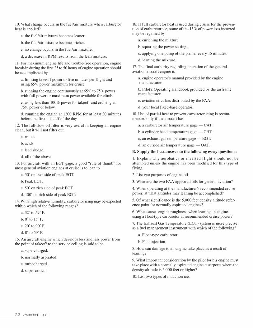
�0 L y c o m i n g F l y e r
10. What change occurs in the fuel/air mixture when carburetor heat is applied?
a. the fuel/air mixture becomes leaner.
b. the fuel/air mixture becomes richer.
c. no change occurs in the fuel/air mixture.
d. a decrease in RPM results from the lean mixture.
11. For maximum engine life and trouble-free operation, engine break-in during the first 25 to 50 hours of engine operation should be accomplished by
a. limiting takeoff power to five minutes per flight and using 65% power maximum for cruise.
b. running the engine continuously at 65% to 75% power with full power or maximum power available for climb.
c. using less than 100% power for takeoff and cruising at 75% power or below.
d. running the engine at 1200 RPM for at least 20 minutes before the first take off of the day.
12. The full-flow oil filter is very useful in keeping an engine clean, but it will not filter out
a. water.
b. acids.
c. lead sludge.
d. all of the above.
13. For aircraft with an EGT gage, a good “rule of thumb” for most general aviation engines at cruise is to lean to
a. 50˚ on lean side of peak EGT.
b. Peak EGT.
c. 50˚ on rich side of peak EGT.
d. 100˚ on rich side of peak EGT.
14. With high relative humidity, carburetor icing may be expected within which of the following ranges?
a. 32˚ to 59˚ F.
b. 0˚ to 15˚ F.
c. 20˚ to 90˚ F.
d. 0˚ to 59˚ F.
15. An aircraft engine which develops less and less power from the point of takeoff to the service ceiling is said to be
a. supercharged.
b. normally aspirated.
c. turbocharged.
d. super critical.
16. If full carburetor heat is used during cruise for the preven-tion of carburetor ice, some of the 15% of power loss incurred may be regained by
a. enriching the mixture.
b. squaring the power setting.
c. applying one pump of the primer every 15 minutes.
d. leaning the mixture.
17. The final authority regarding operation of the general aviation aircraft engine is
a. engine operator’s manual provided by the engine manufacturer.
b. Pilot’s Operating Handbook provided by the airframe manufacturer.
c. aviation circulars distributed by the FAA.
d. your local fixed-base operator.
18. Use of partial heat to prevent carburetor icing is recom-mended only if the aircraft has
a. a carburetor air temperature gage — CAT.
b. a cylinder head temperature gage — CHT.
c. an exhaust gas temperature gage — EGT.
d. an outside air temperature gage — OAT.
B. Supply the best answer to the following essay questions:
1. Explain why aerobatics or inverted flight should not be attempted unless the engine has been modified for this type of flying.
2. List two purposes of engine oil.
3. What are the two FAA-approved oils for general aviation?
4. When operating at the manufacturer’s recommended cruise power, at what altitudes may leaning be accomplished?
5. Of what significance is the 5,000 feet density altitude refer-ence point for normally aspirated engines?
6. What causes engine roughness when leaning an engine using a float-type carburetor at recommended cruise power?
7. The Exhaust Gas Temperature (EGT) system is more precise as a fuel management instrument with which of the following?
a. Float-type carburetor.
b. Fuel injection.
8. How can damage to an engine take place as a result of leaning?
9. What important consideration by the pilot for his engine must take place with a normally aspirated engine at airports where the density altitude is 5,000 feet or higher?
10. List two types of induction ice.
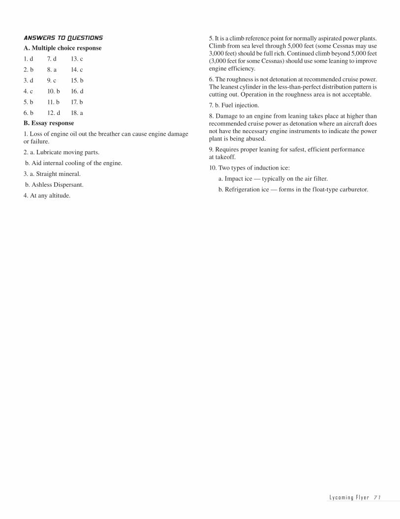
L y c o m i n g F l y e r � �
ANSWERS TO QUESTIONS
A. Multiple choice response
1. d 7. d 13. c
2. b 8. a 14. c
3. d 9. c 15. b
4. c 10. b 16. d
5. b 11. b 17. b
6. b 12. d 18. a
B. Essay response
1. Loss of engine oil out the breather can cause engine damage or failure.
2. a. Lubricate moving parts.
b. Aid internal cooling of the engine.
3. a. Straight mineral.
b. Ashless Dispersant.
4. At any altitude.
5. It is a climb reference point for normally aspirated power plants. Climb from sea level through 5,000 feet (some Cessnas may use 3,000 feet) should be full rich. Continued climb beyond 5,000 feet (3,000 feet for some Cessnas) should use some leaning to improve engine efficiency.
6. The roughness is not detonation at recommended cruise power. The leanest cylinder in the less-than-perfect distribution pattern is cutting out. Operation in the roughness area is not acceptable.
7. b. Fuel injection.
8. Damage to an engine from leaning takes place at higher than recommended cruise power as detonation where an aircraft does not have the necessary engine instruments to indicate the power plant is being abused.
9. Requires proper leaning for safest, efficient performance at takeoff.
10. Two types of induction ice:
a. Impact ice — typically on the air filter.
b. Refrigeration ice — forms in the float-type carburetor.

�� L y c o m i n g F l y e r
NOTES