Embed Size (px)
Citation preview
LY SeriesHYUNDAI WIA CNC Turning Center with Y-Axis

The CNC Turning Center LY Series, designed by Hyundai WIA with years of expertise and the latest technology, is designed to maximize productivity by enhancing rigidity and accuracy of machining.
Technical Leader
Main6″ Main8″ Main10″ Sub5″ Sub6″ VDI30 VDI40
Spindle Turret
● ● ● ●
● ● ● ●
● ● ● ●
● ● ● ●
● ● ● ●
● ● ● ●
MODEL
L150Y
L150SY
L200Y
L200SY
L250Y
L250SY
Y-Axis TailStock
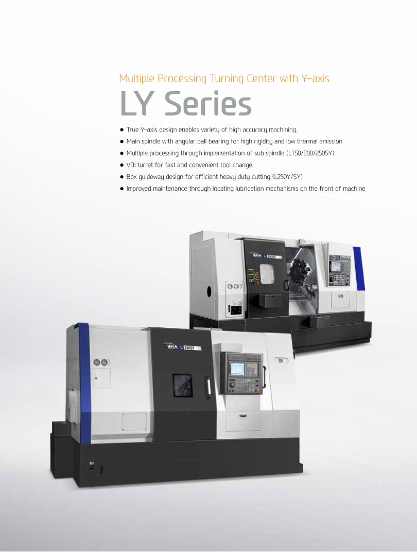
Multiple Processing Turning Center with Y-axis
LY Series● True Y-axis design enables variety of high accuracy machining.
● Main spindle with angular ball bearing for high rigidity and low thermal emission
● Multiple processing through implementation of sub spindle (L150/200/250SY)
● VDI turret for fast and convenient tool change.
● Box guideway design for efficient heavy duty cutting (L250Y/SY)
● Improved maintenance through locating lubrication mechanisms on the front of machine

01 L150/200SY Basic FeaturesHigh productivity Y-axis CNC turning center
LY Series
Main SpindleHeat produced by the main spindle is blocked by applying a symmetric one-piece base and an insulation plate. This enables maintenance of high accuracy even during a long period of machining.
5″ Sub Spindle5" sub spindle joined with Y-axis allows variety of complex machining leading to enhanced productivity.
Ball ScrewIn order to eliminate thermal growth and increase accuracy, all axes are driven by high precision double anchored ballscrews.
The double anchored and pretensioned design provides outstanding positioning and repeatability with minimal thermal growth. Ball screws are connected directly to the servo motor to eliminate backlash.
04
02
03
01 Roller Type LM GuideTo minimize non-cutting time, L150/200SY Series is designed with roller type LM guides which is superior in acc/deceleration.
❖ Y-Axis : Ball Type LM Guide
VDI TurretThe VDI turret secures tools with a single bolt, allowing quick and easy change of tools.

04+
05
LY
Ser
ieS
Y-Ax
is T
ur
nin
g C
enTe
rH
Yun
DAi
WiA
MAC
Hin
e TO
OL
Basic Features
01
03
0402
◉ Rapid Traverse Rate (X/Y/Z/ZB axis)
L150Y | L200Y : 36/10/36 m/min (1,417/393.7/1,417 m/min)
L150SY | L200SY : 36/10/36/30 m/min (1,417/393.7/1,417/1,181 m/min)
◉ Mill Turret (L150SY) : VDI 30◉ Mill Turret (L200SY) : VDI 40
◉ Travel(X/Y/Z/ZB axis)
L150Y | L200Y : 220/80(±40)/550 mm (8.6″/3.1″(±1.6″)/21.6″) L150SY | L200SY : 220/80(±40)/550/750 mm (8.6″/3.1″(±1.6″)/21.6″/29.5″)
◉ Spindle Speed L150SY : Main 6,000 r/min, Sub 6,000 r/min L200Y : 4,000 [4,000] r/min L200SY : Main 4,000, Sub 6,000 r/min
◉ Spindle Motor (Max/Cont.) L150SY : Main 11/7.5 kW, Sub 3.7/2.2 kW (Main 14.7/10 HP, Sub 4.9/2.9 HP)| L200Y : 15/11 [22/18.5] kW (20.1/14.7 [29.5/24.8] HP) L200SY : Main 15/11 kW, Sub 3.7/2.2 kW ( Main 20.1/14.7 HP, Sub 4.9/2.9 HP)
◉ SpindleTorque (Max/Cont.) L150SY : Main 70/47.7 N.m (51.6/35.2 lbf.ft), Sub 26.2/14 N.m (19.3/10.3 lbf.ft) L200Y : 286.6/210.2 [252/211.9] N.m (211.4/155 [185.9/156.3] lbf.ft) L200SY : Main 286.6/210.2 N.m (211.4/155 lbf.ft), Sub 26.2/14 N.m (19.3/10.3 lbf.ft)
Reduction of non-cutting time
[SIEMENS]

Main SpindleHeat produced by the main spindle is blocked by applying a symmetric one-piece base and an insulation plate. This enables maintenance of high accuracy even during a long period of machining.
6″ Sub Spindle6" sub spindle joined with Y-axis allows variety of complex machining leading to enhanced productivity.
Ball ScrewIn order to eliminate thermal growth and increase accuracy, all axes are driven by high precision double anchored ballscrews.
The double anchored and pretensioned design provides outstanding positioning and repeatability with minimal thermal growth. Ball screws are connected directly to the servo motor to eliminate backlash.
04
02
03
Box GuidewayL250SY Series X/Z-axis is designed with box guideways to reduce vibration during operation.Box guideway enables high precision heavy duty cutting.
(❖ Y-Axis : LM Guide)
02 L250SY Basic FeaturesHigh productivity Y-axis CNC turning center
LY Series
01
VDI TurretThe VDI turret secures tools with a single bolt, allowing quick and easy change of tools.

01
03
04
02
◉ Rapid Traverse Rate (X/Y/Z/ZB axis) L250Y : 20/10/24 m/min (787.4/393.7/944.9 ipm) L250SY : 20/10/24/20 m/min (787.4/393.7/944.9/787.4 ipm)
◉ Travel(X/Y/Z/ZB axis) L250Y : 230/110(±55)/675 mm (9″/4.3″(±2.2″)/26.5″) L250SY : 230/110(±55)/675/700 mm (9″/4.3″(±2.2″)/26.5″/27.5″)
◉ Spindle Speed : Main 3,500 [3,500], Sub 6,000 [6,000] r/min
◉ Spindle Motor (Max/Cont.) : Main 22/18.5 [22.2/18.5] kW (29.5/24.8 [29.7/24.8 HP]), Sub 7.5/5.5 [8.4/7] kW (10/7.4 [11.2/9.4] HP)
◉ SpindleTorque (Max/Cont.) : Main 238.2/200.3 [240.2/200.1] N.m (175.7/147.7 [177.2/147.6] lbf.ft), Sub 60/35 [66.8/55.7] N.m (44.2/25.8 [49.3/41.1] lbf.ft)
Powerful & High Precision Cutting Capability
06+
07
LY
Ser
ieS
Y-Ax
is T
ur
nin
g C
enTe
rH
Yun
DAi
WiA
MAC
Hin
e TO
OL
Basic Features
◉ Mill Turret : VDI 40
[SIEMENS]

03 High Precision SpindleLong Lasting High Accuracy & Excellent PerformanceCNC Turning CenterLY Series
Main SpindleThe spindle with high torque and precision provides minimized thermal displacement and high accuracy even during long time processing.

08+
09
LY
Ser
ieS
Y-Ax
is T
ur
nin
g C
enTe
rH
Yun
DAi
WiA
MAC
Hin
e TO
OL
Sub SpindleL150SY/200SY/250SY also feature sub spindles for multiple processing, enabling various processing needs with C-axis control.
Symmetrical Heat Behavior Structure HeadstockRigidity is significantly improvedby enlarging spindle diameter and thickness. Also accuracy is increased due to the use of highly reliable bearings.
This improves durability and provides a high quality surface finish oon every machined parts.
C-Axis ControlC-axis control of main and sub spindle allows machining of various products. Especially with the use of live tools on the Y-axis.
Spindle
0.001°
The standard equipped tail stock can be controlled with M-code or a button on the control panel.
To support the workpiece even more, L250Y is designed with a quill type tail stock.
Tail Stock
◉ Taper
L150Y/200Y : MT#4 (One Touch Type) L250Y : MT#5 (Quill Type)
◉ Quill Dia. L150Y/200Y : Ø56 (2.2″) L250Y : Ø100 (3.9″)
◉ L150SY/200SY : 5″◉ L250SY : 6″
Conveniently saving workpiece setup timeOnce the processing on the main spindle is completed, the sub spindle rotates at the same rate the main spindle and the workpiece is handed over to the sub spindle.
Once the workpiece is secured in the sub spindle back side processing is possible. This enhanced productivity by saving workpiece setup time.

FANUC
0
11[14.7]
7.5[10]
1,500
70[51.6]
47.7[35.2]
6,000
17.5[12.9] 12[8.8]
11kW[14.7HP] (30min)
70N∙m[51.6lbf∙ft] (30min)
47.7N∙m[35.2lbf∙ft] (Cont.)
7.5kW[10HP] (Cont.)
Power(kW[HP]) Torque(N∙m[lbf∙ft]) Power(kW[HP]) Torque(N∙m[lbf∙ft])
Power(kW[HP]) Torque(N∙m[lbf∙ft])
Power(kW[HP]) Torque(N∙m[lbf∙ft]) Power(kW[HP]) Torque(N∙m[lbf∙ft])
Spindle Speed (r/min)
L150Y/SY Main Sp.
0
15[20]
11[14.7]
500
286.6[211.4]
210.2[155]
4,000
35.8[26.4]26.3[19.4]
15kW[20HP] (30min)
286.6N∙m[211.4lbf∙ft] (30min)
210.2N∙m[155lbf∙ft] (Cont.)
11kW[14.7HP] (Cont.)
Spindle Speed (r/min)
L200Y/SY Main Sp.
0
22[29.5]
18.5[24.8]
1,500
238.2[175.7]
200.3[147.7]
6,000
60[44.2]50.5[37.2]
22kW[29.5HP] (30min)
238.2N∙m[175.7lbf∙ft] (30min)
200.3N∙m[147.7lbf∙ft] (Cont.)
18.5kW[24.8HP] (Cont.)
Spindle Speed (r/min)
L250Y/SY Main Sp.
Spindle Speed (r/min)
0
3.7[5]
2.2[3]
1,500
23.5[17.3]
14[10.3]
6,000
5.9[4.3]3.5[2.6]
3.7kW[5HP] (30min)
23.5N∙m[17.3lbf∙ft] (30min)
14N∙m[10.3lbf∙ft] (Cont.)
2.2kW[3HP] (Cont.)
L150Y/SY L200Y/SY Sub Sp.
Spindle Speed (r/min)
0
7.5[10]
5.5[7.4]
1,500
60[44.3]
35[25.8]
6,000
11.9[8.8]8.7[6.4]
7.5kW[10HP] (30min)
60N∙m[44.3lbf∙ft] (30min)
35N∙m[25.8lbf∙ft] (Cont.)
5.5kW[7.4HP] (Cont.)
L250Y/SY Sub Sp.

0
22.2[29.8]
18.5[24.8]
882
240.2[177.2]
200.1[147.6]
3,500
60.5[44.6]50.5[37.2]
22.2kW[29.8HP] (30min)
240.2N∙m[177.2lbf∙ft] (S6-60%)
200.1N∙m[lbf∙ft] (Cont.)
18.5kW[24.8HP] (Cont.)
Power(kW[HP]) Torque(N∙m[lbf∙ft])
Spindle Speed (r/min)
L250Y/SY Main Sp.
0
8.4[11.3]
7[9.4]
1,200 3,600
66.8[49.3]
55.7[41]
6,000
7.8[5.7]6.5[4.8]
8.4kW[11.3HP] (30min)
66.8N∙m[49.3lbf∙ft] (S6-60%)
55.7N∙m[41lbf∙ft] (Cont.)
7kW[9.4HP] (Cont.)
Power(kW[HP]) Torque(N∙m[lbf∙ft])
Spindle Speed (r/min)
L250Y/SY Sub Sp.
0
22[29.5]
18.5[24.8]
833 3,333
252[185.9]
211.9[156.3]
4,000
22kW[29.5HP] (30min)252N∙m[185.9lbf∙ft] (S6-60%)
211.9N∙m[156.3lbf∙ft] (Cont.)18.5kW[24.8HP] (Cont.)
Power(kW[HP]) Torque(N∙m[lbf∙ft])
Spindle Speed (r/min)
L200Y Main Sp.
1PH8 Spindle Motor
10+
11
LY
Ser
ieS
Y-Ax
is T
ur
nin
g C
enTe
rH
Yun
DAi
WiA
MAC
Hin
e TO
OL
Spindle
Machining ability
❖ The above results might be different by types of processing circumstances.
L250SY
Turning 〈Material〈JIS〉:S45C(Carbon steel〉
Processing diameterSide cutting depthSpindle rpmForwarding speedChip discharge
Ø108 6 mm498 r/mim0.3 mm/rev216 cc/min
Main Spindle (O.D)
Turning 〈Material〈JIS〉:S45C(Carbon steel〉
Processing diameterSide cutting depthSpindle rpmForwarding speedChip discharge
Ø943 mm407 r/mim0.2 mm/rev72 cc/min
Sub Spindle (O.D)
Drilling 〈Material〈JIS〉:S45C(Carbon steel〉
Spindle rpmForwarding speedDrill diameterProcessing depthChip discharge
500 r/mim0.05 mm/revØ2010 mm10 cc/min
End Mill
The 1PH8 Series Motor is a high quality and performance motor with the characteristics of maximum concentricity of 10㎛ and short driving time.

04 Y-Axis FunctionHigh speed, High Accuracy, Highly Reliable VDI Turret LY Series
True Y-axis DesignThe VDI turret's true Y-axis design provides accurate positioning.
True Y-axis control and VDI turret allows multi-tasking with single chucking. Also, the compact design provides more flexibility when installing, while maintaining the same machining capability.
Y-Axis
X-Axis

12+
13
LY
Ser
ieS
Y-Ax
is T
ur
nin
g C
enTe
rH
Yun
DAi
WiA
MAC
Hin
e TO
OL
Y-Axis
Mill Tool HolderMachining capability has increased with the addition of straight milling head tool holder, which can machine workpieces from the side, and angular milling head tool holder, which can perform I.D. operations.
A wide variety of additional tool holders for driling and tapping can further enhance machining operations.
The 12 station VDI turret is designed with 3 piece curvic couplings to reduce vibration during heavy duty cutting, which lengthens tool life.
Y-Axis Machining
L250SY Series
L150/200SY Series
Mill Turret (VDI)Angular Milling HeadStraight Milling Head
Side milling Off-center grooving Off-center drilling
◉ Speed : 4,000 rpm
◉ Output (Max.) : 5.5 kW (7.4 HP)
◉ Collet size :Ø20 (0.8″) (ER32)
◉ Live Tool Type : VDI 40
◉ Speed : 4,000 rpm
◉ Output (Max.) : 2.7 kW (3.6 HP)
◉ Collet size : Ø20 (0.8″) (ER32)
◉ Live Tool Type : VDI 30/VDI 40
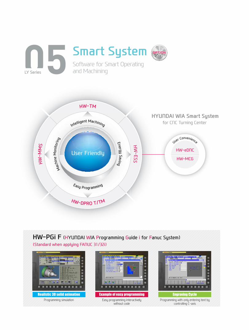
05 Smart SystemSoftware for Smart Operating and MachiningLY Series
Machine Monitoring
Energy SavingIntelligent Machining
Easy Programming
HW-MMS HW
-ESS
HW-DPRO T/TM
User Friendly
HW-TM
HYUNDAI WIA Smart System for CNC Turning Center
User Convenience
HW-eDNC
HW-MCG
HW-PGi F (HYUNDAI WIA Programming Guide i for Fanuc System)(Standard when applying FANUC 31/32i)
Realistic 3D solid animationProgramming simulation
Example of easy programmingEasy programming interactively
without code
Engraving CycleProgramming with only entering text by
controlling C-axis

Faster processing and enhanced accuracy in are possiblethrough the HYUNDAI WIA Smart System. The user friendly software and equipment monitoring of the Smart System maximizes productivity.
HW-TMHYUNDAIWIAToolMonitoring
A tool monitoring software which analyzes the load of the spindle motor to determine and monitor possible damage of tools.
HW-MMSHYUNDAIWIAMachineMonitoringSystem
This software is for remote control monitoring of equipment status (mobile, PC.) It checks and manages the state of multiple machines and the progress of processing on a real time basis.
HW-ESSHYUNDAIWIAEnergySavingSystem
An environmental friendly software that reduces the unnecessarily wasted standby power waiting for an operation.
HW-eDNCHYUNDAIWIAethernetDirectNumericalControl
This software allows transmition of NC data between PC and a machine's CNC. The processing programs can be managed on the PC through the ethernet or serial communication.
HW-MCGHYUNDAIWIAMachineGuidance
Software that offers operation, maintenance, management monitoring and various user friendly features.
USB Port(OnlyHANDAIWIAFANUCSeries)Convenience is increased when inputting and outputting program. The USB port is available in addition to the former input output methods such as CF memort card and LAN.
14+
15
LY
Ser
ieS
Y-Ax
is T
ur
nin
g C
enTe
rH
Yun
DAi
WiA
MAC
Hin
e TO
OL
HYUNDAI WIA Smart System
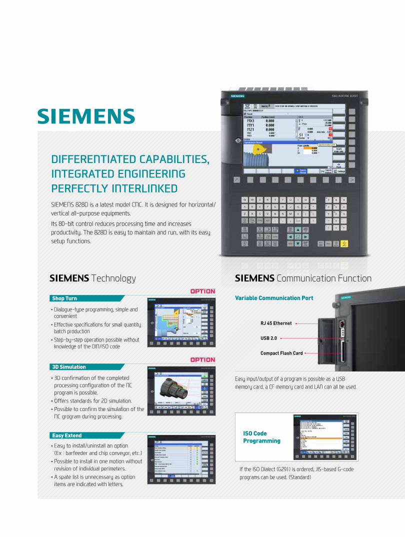
DIFFERENTIATED CAPABILITIES, INTEGRATED ENGINEERING PERFECTLY INTERLINKEDSIEMENS 828D is a latest model CNC. It is designed for horizontal/vertical all-purpose equipments.
Its 80-bit control reduces processing time and increases productivity. The 828D is easy to maintain and run, with its easy setup functions.
• Dialogue-type programming, simple and convenient
• Effective specifications for small quantity batch production
• Step-by-step operation possible without knowledge of the DIN/ISO code
Shop Turn
• 3D confirmation of the completed processing configuration of the NC program is possible.
•Offers standards for 2D simulation.• Possible to confirm the simulation of the
NC grogram during processing.
3D Simulation
• Easy to install/uninstall an option (Ex : barfeeder and chip conveyor, etc.)
• Possible to install in one motion without revision of individual perimeters.
• A spate list is unnecessary as option items are indicated with letters.
Easy Extend
Easy input/output of a program is possible as a USB memory card, a CF memory card and LAN can all be used.
RJ 45 Ethernet
USB 2.0
Compact Flash Card
Variable Communication Port
If the ISO Dialect (G291) is ordered, JIS-based G-code programs can be used. (Standard)
SIEMENS Technology SIEMENS Communication Function
ISO CodeProgramming
16+
17
LY
Ser
ies
Y-Ax
is C
nC
Tur
ning
Cen
ter
HYu
nD
Ai W
iAM
ACH
ine
TOO
L
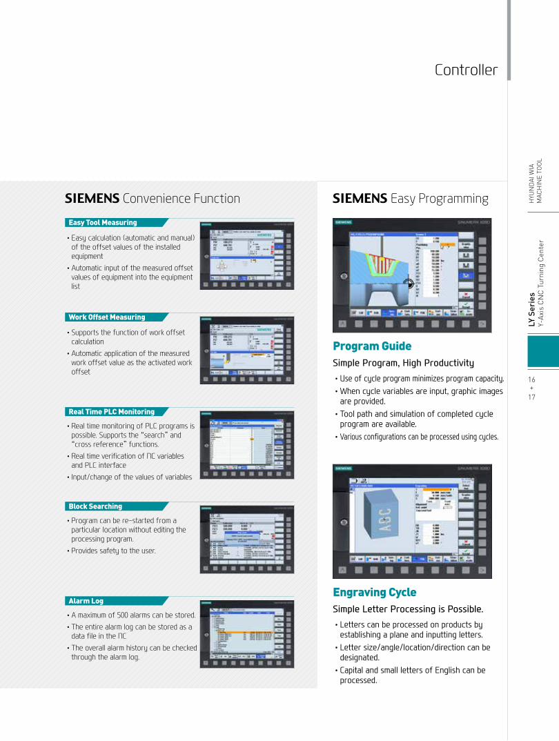
SIEMENS Convenience Function SIEMENS Easy Programming
• Easy calculation (automatic and manual) of the offset values of the installed equipment
• Automatic input of the measured offset values of equipment into the equipment list
Easy Tool Measuring
• Supports the function of work offset calculation
• Automatic application of the measured work offset value as the activated work offset
Work Offset Measuring
• Real time monitoring of PLC programs is possible. Supports the “search” and “cross reference” functions.
• Real time verification of NC variables and PLC interface
• Input/change of the values of variables
Real Time PLC Monitoring
• Program can be re-started from a particular location without editing the processing program.
• Provides safety to the user.
Block Searching
• A maximum of 500 alarms can be stored. • The entire alarm log can be stored as a
data file in the NC • The overall alarm history can be checked
through the alarm log.
Alarm Log
•Useofcycleprogramminimizesprogramcapacity.•Whencyclevariablesareinput,graphicimagesareprovided.•Toolpathandsimulationofcompletedcycleprogramareavailable.•Variousconfigurationscanbeprocessedusingcycles.
•Letterscanbeprocessedonproductsbyestablishingaplaneandinputtingletters.•Lettersize/angle/location/directioncanbedesignated.•CapitalandsmalllettersofEnglishcanbeprocessed.
Program Guide Simple Program, High Productivity
Engraving CycleSimple Letter Processing is Possible.
Controller

06LY Series
User ConvenienceVarious Devices for User Convenience
Automatic Q-Setter
Quick and accurate tool calibration can be done by contacting the tool tip with the sensor. This process is done easily with the use of M-Code and the calibration process takes roughly 30 seconds.
Precision Device
Z-Axis Linear ScaleLinear scale increases positioning accuracy and reduces thermal displacement, this ensures high quality end product manufacturing.
Environment Device
Automation System
Mist CollectorMist Collector reduces the amount of smoke and oil mist in the air. This helps build a safe and comfortable working environment and improve durability.
Parts CatcherParts catcher collects machined products without the need to open the door. This option can increase productivity especially in automation system.
Oil SkimmerAn oil skimmer can increase coolant and tool life by removing tramp oil contaminants.

Bar Feeder System
Parts ConveyorThe parts conveyor transfers the finished workpiece unloaded by the parts catcher for user convenience.
Long Type 3m (118.1″)
Max load processing capa. Ø42 (1.7″)
Shot Type 1.5m (59.1″)
Max load processing capa. Ø65 (2.6″)
Bar Feeder Bar feeder system enables automation which leads to efficiency improvement.
Round Bar Material
Bar Feeder Machining Parts Catcher Parts Conveyor
Bar Feeder Machining Process
LY
Ser
ieS
Y-Ax
is T
ur
nin
g C
enTe
rH
Yun
DAi
WiA
MAC
Hin
e TO
OL
Optional
18+
19

SPECIFICATIONS
Standard & Optional
Main SpindleHollow Chuck 3 Jaw
Main SpindleSolid Chuck 3 Jaw
Sub SpindleHollow Chuck 3 JawSub SpindleSolid Chuck 3 JawStandard Soft Jaw (1set)Chuck Clamp Foot Switch2 Steps Hyd, Pressure DeviceSpindle Inside Stopper5° IndexCs-Axis (0.001°)2 Steps Chuck Foot SwitchChuck Open/Close Confirmation DeviceSub Spindle Foot SwitchTurretTool HolderMill TurretStraight Milling Head
Angular Milling Head
SUB Angular Milling HeadStraight Milling HeadAngular Milling HeadSUB Angular Milling HeadBoring SleeveDrill SocketU-Drill HolderU-Drill Holder SleeveSwivel HeadTail Stock & Steady RestOne Touch Tail StockQuill Type Tail StockBuilt-In Tail StockProgramable Tail StockManual Type Hyd. Steady RestStandard Live CenterHigh Precesion Live Center2 Steps Tail Stock Pressure SystemTail Stock Foot SwitchQuill Forward/Reverse Confirmation DeviceCoolant & Air BlowStandard Coolant (Nozzle)Chuck Coolant (Upper Chuck)Gun CoolantThrough Spindle Coolant (Only for Special Chuck)Chuck Air Blow (Upper Chuck)Sub Spindle Air BlowTail Stock Air Blow (Upper Tail Stock)Turret Air BlowAir GunThrough Spindle Air Blow (Only for Special Chuck)
High Pressure Coolant
Power Coolant System (For Automation)Coolant ChillerChip Disposal
Coolant Tank
Chip Conveyor Hinge(Tank Position/Chip Disposal) ScraperSpecial Chip Conveyor (Drum Filter)
Chip Wagon
6″8″10″12″6″8″10″12″5″6″5″6″
RadialCollet Type,2eaCollet Type,2eaCollet Type,1eaCollet Type,1eaAdapter TypeAdapter TypeAdapter Type
1.5Bar (21.7psi)6Bar (87psi)14.5Bar (210.2psi)20Bar (290psi)
220ℓ(58.1 gal)250ℓ(66 gal)Front (Right)Rear (Rear)
Standard (180ℓ[47.5 gal])Swing (200ℓ[52.8 gal])Large Swing (290ℓ[76.6 gal])Large Size (330ℓ[87.2 gal])Customized
Spindle
● : Standard ○ : Option ☆ : Prior Consultation - : Non applicable
L150Y/SY L200Y/SY L250Y/SY ● - - ○ ● - - ○ ● - - ○ ○ - - ○ ○ - - ○ ○ - - ○ SY ● SY ● - - - SY ● SY● SY● - - - SY ● ● ● ● ● ● ● ○ ○ ○ ☆ ☆ ☆ ☆ ☆ ☆ ● ● ● ○ ○ ○ ○(CE:●) ○(CE:●) ○(CE:●) SY ● SY ● SY ● ● ● ● ● ● ● ● ● ● Y ● Y ● Y ● SY ● SY ● SY ● SY ● SY ● SY ● ○ ○ ○ ○ ○ ○ ○ ○ ○ ● ● ● ● ● ● ○ ○ ○ ○ ○ ○ ☆ ☆ ☆ Y ● Y ● - - - Y ● - - Y○ - - Y○ - - Y☆ Y ● Y ● Y ● Y ○ Y ○ Y ○ Y ☆ Y ☆ Y ☆ Y ● Y ● Y ● - - Y ○ ● ● ● ○ ○ ○ ○ ○ ○ ☆ ☆ ☆ ○ ○ ○ SY ○ SY ○ SY ○ Y ○ Y ○ Y ○ ☆ ☆ ☆ ○ ○ ○ ☆ ☆ ☆ - - ● ● ● ○ ○ ○ ○ - - ○ ☆ ☆ ☆ ☆ ☆ ☆ - - ● ● ● - ○ ○ ○ ○ ○ - ☆ ☆ ☆ ○ ○ ○ ○ ○ ○ ○ ○ ○ ○ ○ ○ ☆ ☆ ☆
L150Y/SY L200Y/SY L250Y/SY ● ● ● ● ● ● ○(CE:●) ○(CE:●) ○(CE:●) ● ● ● ☆ ☆ ☆
● ● ● ○ ○ ○ ○ ○ ○ ○ ○ ○ ○ ○ ○ - ●/- ● ○ ○ ○ - ●/- ● ○ ○ ○ ○ ○ ○ ○ ○ ○ ○ ○ ○ ○ ○ ○ ○ ○ ○ ○ ○ ○ - ○/- ○ ☆ ☆ ☆ ○ Y○ - - SY○ - - - Y ○ - - SY ○ ○ ○ ○ ○ ○ ○ ● ● ● ○ ○ ○ ○ ○ ○ ☆ ☆ ☆ ○ ○ ○ ☆ ☆ ☆ ○ ○ ○ ○ ○ ○ ○ ○ ○ ☆ ☆ ☆ ☆ ☆ ☆ ○ ○ ○ ○ ○ ○ ☆ ☆ ☆ ☆ ☆ ☆ ○ ○ ○ ☆ ☆ ☆ ○ ○ ○ ☆ ☆ ☆ ○ ○ ○ ○ ○ ○ ○ ○ ○ SY ○ SY ○ SY ○ SY ○ SY ○ SY ○ ☆ ☆ ☆ ☆ ☆ ☆ ● ● ●
● ● -
- - ●
☆ ☆ ☆ ○ ○ ○ ○ ○ ○ ☆ ☆ ☆ ☆ ☆ ☆ ● ● ● ☆ ☆ ☆ ☆ ☆ ☆
Door Inter-LockTotal Splash GuardChuck hydraulic pressure maintenance interlockBack Spin Torque Limiter (BST)Torque LimiterElectric DeviceCall LightCall LightCall Light & BuzzerElectric Cabinet Light
Spindle Load Meter
Spindle Speed Meter
Work CounterTotal CounterTool Counter
Multi Tool Counter
Electric Circuit Breaker
ABS Encoder
AVR(Auto Voltage Regulator)
Transformer
Auto Power OffMeasurementQ-SetterAutomatic Q-SetterWork Close Confirmation Device(Only for Special Chuck)Work SetterLinear ScaleCoolant Level Sensor (Only for Chip Conveyor)EnvironmentAir ConditionerDehumidifierOil Mist CollectorOil Skimmer (Only for Chip Conveyor)MQL (Minimal Quantity Lubrication)Fixture & Automation
Auto Door
Auto Shutter (Only for Automatic System)Sub Operation PannelBar Feeder InterfaceBar Feeder (FEDEK)Extra M-Code 4eaAutomation Interface
I/O Extension (IN & OUT)
Parts Catcher
Sub Spindle Work Pusher (Spring Type)Turret Work Pusher (For Automation)Parts ConveyorHyd. DeviceStandard Hyd. Cylinder
Standard Hyd. Unit
S/WMachine Guidance (HW-MCG : FANUC)Tool Monitoring (HW-TM : FANUC)DNC Software (HW-eDNC : FANUC)Energy Saving System (HW-ESS : FANUC)Machine Monitoring System (HW-MMS : FANUC)ETCTool BoxCustomized ColorCAD & CAM
1 Color : ■3 Color : ■■■3 Color : ■■■B
FANUCSIEMENSFANUCSIEMENSDigitalDigitalDigital6ea9ea
FANUCSIEMENS
25kVA30kVA35kVA40kVA
TACOSMC
Z Axis
StandardHigh Speed
16Contact32ContactMain SP.Sub SP.
50bar(725psi)/15ℓ(4gal)50bar(725psi)/20ℓ(5.3gal)
Need Munsel No.
Safety Device
Specifications are subject to change without notice for improvement.

unit : mm(in)External Dimensions
1200
(47.
2)
380(15)
1327 (52.2)
1707
(67.
2)310
(12.2)
SPINDLE CENTER
(SPINDLE)
280
(11)
1117
(44)
1235
(52.
2)D
OO
R O
PE
N90
5 (3
5.6)
49(1.9)
479(18.9)
638 (25.1)
1707 (67.2)
33(1.3)
Right Side Chip Conveyor
Right Side Chip Conveyor
1110 (43.7) 750 (29.5) 1185 (46.7)
717(28.2)
L150Y/SY708(27.9)
L200Y/SY
3045 (119.9)
4304 (169.4)
3045 (119.9)
4306 (169.5)
R500
SPECIFICATIONS
20+
21
LY
Ser
ieS
Y-Ax
is T
ur
nin
g C
enTe
rH
Yun
DAi
WiA
MAC
Hin
e TO
OL
L150SY SeriesL200SY Series

unit : mm(in)External Dimensions
1945
(76.
6)
3221 (126.8)
3461 (136.3) 1278 (50.3)
3461 (136.3) 1278 (50.3)
487(19.2)
2216
(87.
2)
2216
(87.
2)50
0(1
9.7)
R500
1127
(44.
4)
478
(18.
8)
1058
(41.
7)
1950 (76.8)
1423 (56)
240(9.4)
1200
(47.
2)
L250SY Series
SPECIFICATIONS

unit : mm(in)Tooling System
Specifications are subject to change without notice for improvement.
SPECIFICATIONS
22+
23
LY
Ser
ieS
Y-Ax
is T
ur
nin
g C
enTe
rH
Yun
DAi
WiA
MAC
Hin
e TO
OL
L150/200SY Series
Straight Mill Holder
Angular Mill Holder
Sub Angular Mill Holder
VDI 3012 StationsL150Y/SY
VDI 4012 StationsL200Y/SY
Right/Left
Sub
Single
Standard
Standard
Standard (Sub)
Ø8 (5/16″)
Ø10 (3/8″)
Ø12 (1/2″)
Ø16 (5/8″)
Ø20 (3/4″)
Ø25 (1″)
Ø32 (1 1/4″)
MT 1 x MT 2
MT 2
O.D Holder
O.D Holder
Facing Holder
I.D Holder
Straight Mill Holder
Angular Mill Holder
Boring
Drill
ER Collet
Turning Holder
Driven Holder
Boring Holder
Socket
ITEM L150Y L150SY L200Y L200SY
4 2 4 2
- 2 - 2
2 2 2 2
2 2 2 2
2 2 2 2
2 1 2 1
- 1 - 1
1 1 1 1
1 1 1 1
1 1 1 1
1 1 1 1
1 1 1 1
1 1 1 1
- - 1 1
1 1 1 1
1 1 1 1
1 Set 1 Set 1 Set 1 Set
Tooling Parts Detail

unit : mm(in)Tooling System
Straight Mill Holder
Angular Mill Holder
Sub AngularMill Holder
VDI 4012 Stations
Main (Right/Left)
Sub (Right/Left)
Main
Sub
Single
Sub
Standard
Standard
Standard (Sub)
Ø8 (5/16″)
Ø10 (3/8″)
Ø12 (1/2″)
Ø16 (5/8″)
Ø20 (3/4″)
Ø25 (1″)
Ø32 (1 1/4″)
MT 1 x MT 2
MT 2
O.D Holder
Facing Holder
I.D Holder
Straight Mill Holder
Angular Mill Holder
Boring
Drill
ER Collet
Turning Holder
Driven Holder
Boring Holder
Socket
ITEM L250Y L250SY
4 2
- 2
2 1
- 1
2 1
- 1
2 2
2 1
- 1
1 1
1 1
1 1
1 1
1 1
1 1
1 1
1 1
1 1
1 Set 1 Set
Tooling Parts Detail
Specifications are subject to change without notice for improvement.
SPECIFICATIONS
L250SY Series

unit : mm(in)Interference
(6.1)
402 (15.8)
402 (15.8)
200 (7.9)
135(5.3)
65(2.6)
172(6.8)
48(1.9)
30(1.2)
160 (6.3) 122 (4.8)
220 (8.7)
35 (1.4)98
(3.9)85
(3.3)
(6.1) (1.4)(3.3) (7.5)
(18.3)
(12.2)
Ø281 (Ø11.1)
Ø250
(Ø9.8)
Ø31
0 (Ø
12.2
)Ø276
(Ø10.9)
Ø293
(Ø11.5)
Ø276
(Ø10.9) Ø680 (Ø26.8)
Ø244 (Ø9.6)
Ø344 (Ø13.5)
Ø204.5
(Ø8.1
)
Ø204.5(Ø8.1) 100
(3.9)
Ø620 (Ø24.4)
Ø620 (
Ø24.4)
Ø246
(Ø9.
7)
Ø245
(Ø9.
6)
Ø241
(Ø9.5)
Ø240
(Ø9.4)
Ø40
(Ø1 1
/2)
Ø40(Ø1 1/2)
Ø20
(Ø0.
8)
Ø20
(Ø0.
8)
89(3
.5)
103.2(4.1)
103.2(4.1)
100
(3.9
)
24+
25
LY
Ser
ieS
Y-Ax
is T
ur
nin
g C
enTe
rH
Yun
DAi
WiA
MAC
Hin
e TO
OL
SPECIFICATIONS
L250SY
L150SY
L200SY

unit : mm(in)Tooling Travel Range
L150SY
Straight Mill Holder
O.D Tool Holder I.D Tool Holder
Sub O.D Tool Holder Facing Tool Holder
Sub Angular Mill Holder
Angular Mill Holder
SPECIFICATIONS

unit : mm(in)Tooling Travel Range
L200SY
26+
27
LY
Ser
ieS
Y-Ax
is T
ur
nin
g C
enTe
rH
Yun
DAi
WiA
MAC
Hin
e TO
OL
SPECIFICATIONS
Straight Mill Holder
O.D Tool Holder I.D Tool Holder
Sub O.D Tool Holder Facing Tool Holder
Sub Angular Mill Holder
Angular Mill Holder
(0.9)
(1.65)
(2.17) (0.89)
(1.36)(16.56)
(0.2)
(0.49)
(4.8
)
(0.3
9)(3
.54)
(2.6
4)(1
.34) (3
.11)
(19.
5)(4
.74)
(1.0
6)
(7.19)(21.65)
(21.65)
(0.7
5)(0
.16) (5
.59)
(3.0
7)
(1.65) (13.47) (15.59)
(0.33) (3.44) (10.56) (1.27)
(0.1
6)
(2.3
2)(5
.59)
(4.3
3)(3
.58) (5.4
1)(2
.34)
(6.4
8)(1
.24)
(1.65)(2.1)(21.65)
(2.81) (5.04) (13.1)(0.7
5)(0
.16)
(1.3
6)(6
.4)
(4.8
)(3
.86)
(0.69)
(2.81) (5.04) (13.1)
(1.65) (1.67)(21.65)
(0.7
5)(0
.16)
(5.6
)(3
.07)
(6.7
)(1
.06)
(2.81) (5.04) (13.1)(0.69)
(1.65) (4.33)
(0.7
5)(0
.16)
(4.4
2)(3
.5)
(6.4
)(1
.36)
(21.65)
(2.81) (5.04) (13.1)(0.69) (0.69)
(1.65)(2.6)(21.65)
(0.7
5)
(5.6
)(3
.07)
(6.7
)(1
.06)
(2.81) (5.04) (13.1)(0.69)

unit : mm(in)Tooling Travel Range
L250SY
Straight Mill Holder
Angular Mill Holder
Boring Holder Sub Angular Mill HolderSub Boring Holder
O.D Tool Holder
Grooving Holder Sub Grooving Holder
Sub O.D Tool Holder
SPECIFICATIONS

unit : mm(in)Tooling Travel Range
L250SY
Straight Mill Holder
Angular Mill Holder
Boring Holder Sub Angular Mill HolderSub Boring Holder
O.D Tool Holder
Grooving Holder Sub Grooving Holder
Sub O.D Tool Holder
28+
29
LY
Ser
ieS
Y-Ax
is T
ur
nin
g C
enTe
rH
Yun
DAi
WiA
MAC
Hin
e TO
OL
SPECIFICATIONS

Swing Over the Bed
Swing Over the Carriage
Max. Turning Dia.
Max. Turning Length
Bar Capacity Main
Sub
Chuck Size Main
Sub
Spindle Bore Main
Sub
Spindl Speed (rpm) Main
Sub
Motor (Max/Cont.) Main
Sub
Torque (Max/Cont.) Main
Sub
Spindle Type Main
Sub
Spindle Nose Main
Sub
C-axis Indexing
Travel X/Y
Z/ZB
Rapid Traverse Rate X/Y
Z/ZB
Slide Type
No. of Tool
Tool Size OD
ID
Indexing Time
Y-Axis Type
Motor
Milling Tool Speed (rpm)
Touque
Collet Size
Type
Taper
Quill Dia.
Quill Travel
Travel
Coolant Tank
Lubricating Tank
Electric Power Supply
Thickness of Power Cable
Voltage
Floor Space (L×W)
Height
Weight
Controller
CAPACITY
FEED
TANkCPAPCITY
TAIlSTOCk
SPINDlE
TURET
lIvE TOOl
MACHINE
NC
POWERSUPlY
mm(in)
mm(in)
mm(in)
mm(in)
mm(in)
mm(in)
mm(in)
mm(in)
mm(in)
mm(in)
r/min
r/min
kW(HP)
kW(HP)
N.m(lbf.ft)
N.m(lbf.ft)
-
-
-
-
deg
mm(in)
mm(in)
m/min(ipm)
m/min(ipm)
-
EA
mm(in)
mm(in)
sec/step
-
kW(HP)
r/min
N.m(lbf.ft)
mm(in)
-
-
mm(in)
mm(in)
mm(in)
ℓ(gal)
ℓ(gal)
kVA
Sq
V/Hz
mm(in)
mm(in)
kg(lb)
-
Ø550 (21.7″)
Ø350 (13.8″)
Ø240 (9.4″)
530 (20.9″)
Ø45 (1.8″)
- Ø33 (1.3″)
Ø169 (6.7″)
- Ø135 (5.3″)
Ø53 (2.1″)
- Ø43 (1.7″)
6,000
- 6,000
11/7.5 (15/10)
- 3.7/2.2 (5/3)
70/47.7 (51.6/35.2)
- 23.5/14 (17.3/10.3)
BELT
- BELT
A2-5
- FLAT Ø110 (4.3″)
0.001˚
220/80 {±40} (8.7″/3.1″)
550 (21.7″) 550/750 (21.7″/29.5″)
36/10 (1,417/393.7)
36 (1,417) 36/30 (1,417/1,181)
LM GUIDE
12
□20 (0.8″)
Ø32 (1.3″)
0.3
Perpendicular Type
2.7 (3.6)
4,000
12 (8.8)
Ø20 (0.8″) ER32
VDI30
MT4 -
Ø56 (2.2″) -
-
720 (28.3″) -
250 (66)
1.8 (0.5)
19 23
OVER 25
220/60 (200/50)
3,045×1.705 (119.9″×67.1″)
2,021 (79.6″)
4,400 (9,700) 4,500 (9,921)
FANUC 32i-A FANUC 31i-A
Specifications are subject to change without notice for improvement.
ITEM L150Y L150SY
Specifications [ ] : Option
SPECIFICATIONS

Swing Over the Bed
Swing Over the Carriage
Max. Turning Dia.
Max. Turning Length
Bar Capacity Main
Sub
Chuck Size Main
Sub
Spindle Bore Main
Sub
Spindl Speed (rpm) Main
Sub
Motor (Max/Cont.) Main
Sub
Main
Torque (Max/Cont.)
Sub
Spindle Type Main
Sub
Spindle Nose Main
Sub
C-axis Indexing
Travel X/Y
Z/ZB
Rapid Traverse Rate X/Y
Z/ZB
Slide Type
No. of Tool
Tool Size OD
ID
Indexing Time
Y-Axis Type
Motor
Milling Tool Speed (rpm)
Touque
Collet Size
Type
Taper
Quill Dia.
Quill Travel
Travel
Coolant Tank
Lubricating Tank
Electric Power Supply
Thickness of Power Cable
Voltage
Floor Space (L×W)
Height
Weight
Controller
CAPACITY
FEED
TANkCPAPCITY
TAIlSTOCk
SPINDlE
TURET
lIvE TOOl
MACHINE
NC
POWERSUPlY
mm(in)
mm(in)
mm(in)
mm(in)
mm(in)
mm(in)
mm(in)
mm(in)
mm(in)
mm(in)
r/min
r/min
kW(HP)
kW(HP)
N.m(lbf.ft)
N.m(lbf.ft)
-
-
-
-
deg
mm(in)
mm(in)
m/min(ipm)
m/min(ipm)
-
EA
mm(in)
mm(in)
sec/step
-
kW(HP)
r/min
N.m(lbf.ft)
mm(in)
-
-
mm(in)
mm(in)
mm(in)
ℓ(gal)
ℓ(gal)
kVA
Sq
V/Hz
mm(in)
mm(in)
kg(lb)
-
Ø550 (21.7″)
Ø350 (13.8″)
Ø240 (9.4″)
530 (20.9″)
Ø65 (2.6″)
- Ø33 (1.3″)
Ø210 (8.3″)
- Ø135 (5.3″)
Ø78 (3.1″)
- Ø43 (1.7″)
4,000[4,000] 4,000
- 6,000
15/11 (20/15) [22/18.5(29.5/24.80] 15/11 (20/15)
- 3.7/2.2 (5/3)
286.6/210.2(211.3/155) 286.6/210.2 (211.4/155)
[252/211.9(185.9/156.2)]
- 23.5/14 (17.3/10.3)
BELT
- BELT
A2-6
- FLAT Ø110 (4.3″)
0.001˚
220/80 {±40} (8.7″/3.1″)
550 (21.7″) 550/750 (21.7″/29.5″)
36/10 (1,417/393.7)
36 (1,417) 36/30 (1,417/1,181)
LM GUIDE
12
□25 (1″)
Ø40 (1.6″)
0.28
Perpendicular Type
2.7 (3.6)
4,000
12 (8.8)
Ø20 (0.8″) ER32
VDI 40
MT4 -
Ø56 (2.2″) -
-
720 (28.3″) -
250 (66)
1.8 (0.5)
22 26
OVER 25
220/60 (200/50)
3,045×1.705 (119.9″×67.1″)
2,021 (79.6″)
4,500 (9,921) 4,600 (10,141)
FANUC 32i-B [SIEMENS 828D] FANUC 31i-A
Specifications are subject to change without notice for improvement.
ITEM L200Y L200SY
Specifications [ ] : Option
30+
31
LY
Ser
ieS
Y-Ax
is T
ur
nin
g C
enTe
rH
Yun
DAi
WiA
MAC
Hin
e TO
OL
SPECIFICATIONS

Ø620 (24.4″)
Ø490 (19.3″)
Ø310 (12.2″)
620 (24.4″)
Ø76 (3″)
- Ø45 (1.8″)
Ø255 (10″)
- Ø169 (6.6″)
Ø95 (3.7″)
- Ø53 (2.1″)
3,500 [3,500]
- 6,000 [6,000]
22/18.5 (30/25) [22.2/18.5 (30/25)]
- 7.5/5.5 (10/7.4) [8.4/7(11.29.3)]
238.2/200.3(175.6/147.7) [240.2/200.1 (177.1/147.5)]
- 60/35 (44.2/25.8) [66.8/55.7 (49.3/41.1)]
BELT
- BELT
A2-8
- A2-5
0.001˚
230/110 {±55} (9.1″/4.3″)
675 (26.6″) 675/700 (26.6″/27.6″)
20/10 (787.4/393.7)
24 (944.9) 24/20 (944.9/787.4)
BOX GUIDE
12
□25 (1″)
Ø40 (1.6″)
0.33
Perpendicular Type
5.5 (7.4)
4,000
30 (22.1)
Ø20 (0.8″) ER32
VDI 40
MT5 -
Ø100 (3.9″) -
120 (4.7″) -
750 (29.5″) -
220 (58.1)
1.8 (0.5)
29 37
OVER 35
220/60 (200/50)
3,202×1,988 (126.1″×78.3″)
2,181 (85.9″)
6,500 (14,330)
FANUC 32i-B [SIEMENS 828D]
Specifications are subject to change without notice for improvement.
Swing Over the Bed
Swing Over the Carriage
Max. Turning Dia.
Max. Turning Length
Bar Capacity Main
Sub
Chuck Size Main
Sub
Spindle Bore Main
Sub
Spindl Speed (rpm) Main
Sub
Motor (Max/Cont.) Main
Sub
Torque (Max/Cont.) Main
Sub
Spindle Type Main
Sub
Spindle Nose Main
Sub
C-axis Indexing
Travel X/Y
Z/ZB
Rapid Traverse Rate X/Y
Z/ZB
Slide Type
No. of Tool
Tool Size OD
ID
Indexing Time
Y-Axis Type
Motor
Milling Tool Speed (rpm)
Touque
Collet Size
Type
Taper
Quill Dia.
Quill Travel
Travel
Coolant Tank
Lubricating Tank
Electric Power Supply
Thickness of Power Cable
Voltage
Floor Space (L×W)
Height
Weight
Controller
CAPACITY
FEED
TANkCPAPCITY
TAIlSTOCk
SPINDlE
TURET
lIvE TOOl
MACHINE
NC
POWERSUPlY
mm(in)
mm(in)
mm(in)
mm(in)
mm(in)
mm(in)
mm(in)
mm(in)
mm(in)
mm(in)
r/min
r/min
kW(HP)
kW(HP)
N.m(lbf.ft)
N.m(lbf.ft)
-
-
-
-
deg
mm(in)
mm(in)
m/min(ipm)
m/min(ipm)
-
EA
mm(in)
mm(in)
sec/step
-
kW(HP)
r/min
N.m(lbf.ft)
mm(in)
-
-
mm(in)
mm(in)
mm(in)
ℓ(gal)
ℓ(gal)
kVA
Sq
V/Hz
mm(in)
mm(in)
kg(lb)
-
ITEM L250Y L250SY
Specifications [ ] : Option
SPECIFICATIONS

SIEMENS 828D (L200Y | L250Y/SY)Control function
Max. configuration of Axis
Max. configuration of Axis and sp.
Least Command/inputFeed functionFeedrate OverrideRapid Traverse OverrideAcceleration with jerk limitationProgrammable accelerationFollow-up modeMeasuring system 1 and 2, selectableSeparate path feed for corners and chamfersTravel to fixed stopSpindle functionSpindle OverrideSpindle OrientationSpindle Speed LimitationRigid TappingInterpolation functionLinear interpolation AxisCircle via center point and end pointCircle via interpolation pointHelical interpolationUniversal interpolator NURBS(non-uniform rational B splines)Continuous-path mode with programmablerounding clearanceTool functionTool Radius Comp.Zero Offset (G54, G55, G56, G57 ,G58, G59)Programmable Zero OffsetTool managementDisplayCRT / MDISCREEN SAVERManual OperationManual Handle/Jog FeedRepositionReference ApproachSpindle ControlAuto OperationSingle BlockFeed HoldOptional Block SkipMachine LockDry RunSimulationDiagnosis functionAlarm DisplaySpindle Load/rpm MeterPLC status/LAD displayProgram function
Part Program Storage Length
Program NameSubroutine CallAbsolute/incremental CommandScaling, ROTInch / Metric ConversionConversational Cycle ProgramBlock SearchVariable Program (Macro)Read / Write System VariableBackGround EditingMiscellaneous FunctionsLable SkipProgram Stop/EndLookahead , Jerk LimitationFeed &forward control
3 Axis(MS / SY exception)4 Axis(MS / SY machine only)6 Axis(MS / SY exception)8 Axis(MS / SY machine only)0.0001mm / 0.00001inch
0 - 120%F1, 5, 25/50, 100%
50% - 120%
Max. 4 axis
100 EA
10.4˝ Color LCDNone
Ref 1, 2 ApproachStart, Stop, Rev, Jog, Ort.
(2 dimensional)
3MB (MS / SY exception) PPU26x.x5MB (MS / SY machine only) PPU28x.x23 digit(7 level) G90 - G91
(22 Machine)
M - Code
M00, M01, M02, M30
Program functionISO Dialect Interpreter(G291) (Fanuc Program exe)
Maximum number of tools/cuttings
Number of levels for skip blocks 1Protection FunctionEmergency StopOver TravelContour MonitoringProgram ProtectionAutomation Support Fun.Actual Speed Display(Monitor)Tool Life ManagementWork Count Functionlanguage Function
Two Language switchable
Data TransferRS 232C I/F / EthernetUSB Memory Stick & CF Card
OptionShop Turn3D SimulationDRF offsetTeach -inNumber of levels for skip blocks 8TRACYL (Cylinder interpolation)TRANSMIT (Pole coordinate command)Sister ToolA,B,C SPLINE INTERPOLATIONRCS HOST (Remote Control)Simultaneous Recording (real time monitoring)Analysis of Internal Drive ValuesNetwork Drive Management
Figures in inch are converted from metric values.Specifications are subject to change without notice for improvement.
128/256 (MS / SY exception) PPU26x.x256/512 (MS / SY machine only) PPU28x.x
Soft Limit & Hard O.T
(Time, Parts)(Internal)
(6EA)Chinese Traditional, Czech, Danish, Dutch, Finnish, Hungarian, Japanese, Korean, Polish, Russian, Swedish, Portuguese, Turkish
CONTROLLER
32+
33
LY
Ser
ieS
Y-Ax
is T
ur
nin
g C
enTe
rH
Yun
DAi
WiA
MAC
Hin
e TO
OL

Figures in inch are converted from metric values.Specifications are subject to change without notice for improvement.
CONTROLLER
FANUC 31i-A (L150SY | L200SY)Axis control / Display unit
Controlled axes
Simultaneous controllable axes
Least input increment
Least command increment
High speed HRV controlInch / Metric conversionInterlockMachine lockEmergency stopStored stroke check 1Stored stroke check 2Stored stroke check 3Follow-upServo-off
Backlash compensation
Position switchUnexpected disturbance torque detectionHigh resolution transfer control (HRM)LCD / MDIOperation Automatic operation (memory)MDI operationSearch functionProgram restartWrong operation preventionBuffer registerProgram check functionSingle blockFeed functionsManual jog feedManual handle feedrateFeed commandFeedrate overrideJog overrideRapid traverse overrideOverride cancelFeed per minute / rotationProgram input & interpolation functions
Nano interpolation
DwellThread retractVariable lead threading1st reference point returnReference point return check2nd reference point returnProgram stop / EndTape codeOptional block skipMaximum programmable dimensionsProgram numberAbsolute and incremental programmingDecimal point inputPlane selectionWork coordinate system selectionManual absoluteDirect drawing dimension programmingG code systemProgrammable data inputSub program callCustom macro BAddition of custom macro common variableMultiple repetitive cyclesMultiple repetitive cycles ⅡCanned cycles for turning
Max. 6 axes are availableX, Z axesX, Z, C axes (M type machine)X, Z, B, C, A axes (MS type machine)X, Z, Y, B, C, A axes (SY type machine)2axes / Linear and circular (Max. 4axes)X, Z, Y, B axis : 0.001 mm (0.0001”)C axis : 0.001 degX, Z, Y, B axis : 0.001 mm (0.0001”)C axis : 0.001 deg
G20 / G21Each axis / All axisAll axis
Over-travel
+/- 0~9999 pulses(Rapid traverse & cutting feed)
Back-spin torque limiter (BST)
10.4″ Color LCD
Sequence, program
Dry run., program check
Rapid, jog, handlex1, x10, x100F code feedrate direct command0~200 % (10% units)0~2,000 mm/min[79 ipm]F1, F5, F25 / 50, F100%
Positioning/Linear/Circular(G00/G01/G02, G03)G04, 0~9999.9999 sec
G28, manualG27G30M00, M01 / M02, M30EIA / ISO 1 ea+/- 9999.9999″O+4 digits
G17, G18, G19G52 to G59“ON” fixed
Included chamfering / Corner R`AG1010 Step#100 to #199, #500 to #999
Sub / Main spindle functionM-Code functionM-Code function lockLock sp. speed commandMain sp. constant controlSpindle speed overrideSpindle position decisionRigid tappingTool function / Tool compensationTool functionTool offset pairsTool offsetTool nose radius compensationDirect input of measured toolcompensation value BTool life managementData in/output & editing functionsInput/Output interfaceMemory card input/outputEmbeded ethenetPart program storage lengthNumber of registrable programs expansionMemory lockBackground editingExtended part program editionDisplay, diagnosis & setting functionsSelf-diagnosis functionHistory displayHelp functionExternal messageRun hour / Parts count displayDisplay of actual spindle speed and T codeActual cutting feedrate displayOperating monitor screenGraphic displaySpindle / Servo setting screenSelection of 5 optional languageLCD screen saveAutomatic data backupFunctions according to machine specificationCs contouring controlStored pitch error compensationPolar coordinate interpolationCylindrical interpolationCanned cycles for drillingspindle orientation expansion
OptionHigh speed ethernetOptional block skip3rd & 4th reference point returnG code systemPart program storage lengthTool OffestPoligon TurningHelical interpolationDynamic graphic displayProtection of data at 8 levelsManual guide i
M4 digits
S4 digits, binary outputG96, G9750% to 150% (10% units)
T2 + 264 pairs
G40, G41, G42
RS232C
100Mbps256 KbyteMax. 1,00 programs
Copy, move, change of NC program
Alarm & operation display
Rod meter light
Screen saver
Turn millTurn millTurn millTurn millTurn millTurn mill
100 Mbps (Option board is required)9 ea
B / C512 Kbyte / 1024 Kbyte99 / 200 / 400 EA
Interactive program

Figures in inch are converted from metric values.Specifications are subject to change without notice for improvement.
CONTROLLER
34+
35
LY
Ser
ieS
Y-Ax
is T
ur
nin
g C
enTe
rH
Yun
DAi
WiA
MAC
Hin
e TO
OL
FANUC 32i-A (L150Y)Axis control / Display unit
Controlled axes
Simultaneous controllable axesLeast input increment
Least command increment
High speed HRV controlInch / Metric conversionInterlockMachine lockEmergency stopStored stroke check 1Stored stroke check 2Stored stroke check 3Follow-upServo-off
Backlash compensation
Position switchUnexpected disturbance torque detectionHigh resolution transfer control (HRM)LCD / MDIOperationAutomatic operation (memory)MDI operationSearch functionProgram restartWrong operation preventionBuffer registerProgram check functionSingle blockFeed functionsManual jog feedManual handle feedrateFeed commandFeedrate overrideJog overrideRapid traverse overrideOverride cancelFeed per minute / rotationProgram input & interpolation functions
Nano interpolation
DwellThread retractVariable lead threading1st reference point returnReference point return check2nd reference point returnProgram stop / EndTape codeOptional block skipMaximum programmable dimensionsProgram numberAbsolute and incremental programmingDecimal point inputPlane selectionWork coordinate system selectionManual absoluteDirect drawing dimension programmingG code systemProgrammable data inputSub program callCustom macro BAddition of custom macro common variable
Max. 4 axes are availableX, Z axesX, Z, C axes (M type machine)X, Z, Y, C axes (Y type machine)X, Z, B, C axes (MS type machine)2axes / Linear and circular (Max. 4axes)X, Z, Y, B axes : 0.001 mm (0.0001”)C axis : 0.001 degX, Z, Y, B axes : 0.001 mm (0.0001”)C axis : 0.001 deg
G20 / G21Each axis / All axesAll axes
Over-travel
+/- 0~9999 pulses (Rapid traverse & cutting feed)
Back-spin torque limiter (BST)
10.4″ Color LCD
Sequence, program
Dry run., program check
Rapid, jog, handlex1, x10, x100F code feedrate direct command0~200 % (10% units)0~2,000 mm/min[79 ipm]F1, F5, F25/F50, F100%
Positioning / Linear / Circular (G00 / G01 / G02, G03)G04, 0~9999.9999 sec
G28, manualG27G30M00, M01 / M02, M30EIA / ISO1 ea+/- 9999.9999″O+4 digits
G17, G18, G19G52 to G59“ON” FixedIncluded chamfering / Corner R`AG1010 folds nested
#100 to #199, #500 to #999
Program input & interpolation functionsMultiple repetitive cyclesMultiple repetitive cycles ⅡCanned cycles for turningManual guide iSub / Main spindle functionM-Code functionM-Code function lockLock sp. speed commandMain sp. constant controlSpindle speed overrideSpindle position decisionRigid tappingTool function / Tool compensationTool functionTool offset pairsTool offsetTool nose radius compensationDirect input of measured toolcompensation value BTool life managementData in/output & editing functionsReader / Puncher interfaceMemory card input/outputPart program storage lengthNumber of registrable programs expansionMemory lockBackground editingExtended part program editionDisplay, diagnosis & setting functionsSelf-diagnosis functionHistory displayHelp functionExternal messageRun hour / Parts count displayDisplay of actual spindle speed and T codeActual cutting feedrate displayOperating monitor screenGraphic displaySpindle / Servo setting screenSelection of 5 optional languageErase CRT screen displayAutomatic data backupFunctions according to machine specificationCs contouring controlStored pitch error compensationPolar coordinate interpolationCylindrical interpolationCanned cycles for drillingspindle orientation expansionSpindle synchronous controlTorque controlY axis offsetAngular axis control
OptionHigh speed EthernetOptional block skip3rd & 4th reference point returnG code systemPart program storage lengthPolygon turningHelical interpolationDynamic graphic displayProtection of data at 8 levels
Interactive programming
M4 digits
S4 digits, binary outputG96, G9750% to 150% (10% units)
T2 + 264 pairs
G40, G41, G42
RS232C
256 KbyteMax. 500 programs
Copy, move, change of NC program
Alarm & operation display
Rod meter light
Screen saver
Turn millTurn millTurn millTurn millTurn millTurn mill, Sub spindleSub spindleSub spindleY type machineY type machine
100 Mbps (Option board is required)9 ea
B / C512 Kbyte

Figures in inch are converted from metric values.Design and specifications subject to change without notice.
CONTROLLER
Figures in inch are converted from metric values.Specifications are subject to change without notice for improvement.
FANUC 32i-B [ ] : Option, ☆ Needed technical consultation
Controlled axis / Display / Accuracy compensation
Control axes2 axes (X, Z), 3 axes (X, Z, C)4 axes (X, Z, Y, C), 5 axes (X, Z, B, C, A)6 axes (X, Z, Y, B, C, A)
Simultaneously controlled axes 2 axes [Max. 4 axes]Designation of spindle axes 4 axes (1 path), 6 axes (2 path Total)
Least setting Unit / Least input incrementX, Z, Y, B axes : 0.001 mm (0.0001″)C, A axes : 0.001°
Inch / Metric conversion G20/G21 High response vector controlInterlock All axes / Each axisMachine lock All axes
Backlash compensation ± 0 ~ 9999 pulses(Rapid traverse / Cutting feed)
Position switchLCD / MDI 10.4″ color LCDFeedback Absolute motor feedbackStored stroke check 1 Over travelStored stroke check 2, 3PMC axis controlOperationAutomatic operation (Memory)MDI operationDNC operation Needed DNC software / CF cardProgram restartWrong operation preventionProgram check function Dry run, Program checkSingle blockSearch function Program number / Sequence numberInterpolation functionsNano interpolationPositioning G00Linear interpolation G01Circular interpolation G02, G03Exact stop mode Single : G09, Continuous : G61Dwell G04 0~9999.9999 secSkip G31
Reference position return 1st reference : G28 Ref. position check : G272nd reference : G30
Thread synchronous cuttingThread cutting retractVariable lead thread cuttingMulti / Continuous threadingFeed function / Acc. & Dec. control
Manual feed
Rapid traverse Jog : 0~2,000 mm/min (79 ipm) Manual handle : x1, x10, x100 pulsesReference position return
Cutting Feed command Direct input F codeFeedrate override 0 ~ 200% (10% Unit)Rapid traverse override F1%, F5%, F25% / 50%, F100%Override cancelFeed per minute G98Feed per revolution G99Look-ahead block 1 block Program inputTape Code EIA/ISOOptional block skip 1EAAbsolute / Incremental program G90/G91Program stop / end M00, M01/M02, M30Maximum command unit ±999,999.999 mm (±99,999.9999 inch)Plane selection X-Y : G17, X-Z : G18, Y-Z : G19Workpiece coordinate system G52, G53, 6 pairs (G54 ~ G59)Manual absolute Fixed ON Programmable data input G10Sub program call 10 folds nestedCustom macro #100~#199, #500~#999G code system AProgrammable mirror image G51.1, G50.1G code preventing buffering G4.1Direct drawing dimension program Including Chamfering / Corner RMultiple repetitive cycles Ⅰ, ⅡCanned cycle for turningManual Guide i Conversational auto program
Auxiliary function / Spindle speed functionAuxiliary function M & 4 digitLevel-up M code High speed / Multi / Bypass M codeSpindle speed function S & 4 digit , Binary outputSpindle override 50% ~ 150% (10% Unit)Multi position spindle orientation M19FSSB high speed rigid tappingConstant surface speed control G96, G97Tool function / Tool compensationTool function T & 2 digit + Offset 2 digitTool life management ☆ 256 pairsTool offset pairs 32 pairsTool nose radius compensation G40, G41, G42Geometry / Wear compensationDirect input of offset measured BEditing functionPart program storage size 640m (256KB)No. of registerable programs 500 EAProgram protectBackground editingExtended part program editing Copy, move and change of NC programMemory card program edit Data input / output & Interface
I/O interfaceRS 232C, CF card, USB memoryEmbedded Ethernet interface
Screen hard copyExternal messageExternal key inputExternal workpiece number searchAutomatic data backupSetting, display and diagnosisSelf-diagnosis functionHistory display Alarm & Operator message & OperationRun hour / Parts count displayMaintenance informationActual cutting feedrate displayDisplay of spindle speed / T codeGraphic displayOperating monitor screen Spindle / Servo load etc...Power consumption monitoring Spindle & ServoSpindle / Servo setting screenMulti language display Support 20 languagesDisplay language switching Selection of 5 optional LanguagesLCD Screen Saver Screen saverUnexpected disturbance torque BST (Back spin torque limit)Function for machine typeCs contour control (C & A axes) Mill, MS, Y, SY, LF-Mill, TTMS, TTSYPolar coordinate interpolation Mill, MS, Y, SY, LF-Mill, TTMS, TTSYCylindrical interpolation Mill, MS, Y, SY, LF-Mill, TTMS, TTSYCanned cycle for drilling Mill, MS, Y, SY, LF-Mill, TTMS, TTSYSpindle orientation expansion MS, SY TTS, TTMS, TTSYSpindle synchronous control MS, SY TTS, TTMS, TTSYTorque control MS, SY TTS, TTMS, TTSYY axis offset Y, SY, TTSYArbitrary angular control Y, SY, TTSYComposite / Superimposed control MS, SY TTS, TTMS, TTSYBalance cutting MS, SY TTS, TTMS, TTSY
OptionAdditional optional block skip ☆ 9 EAFast ethernet Needed option boardData server Needed option boardProtection of data at 8 levelsTool offset pairs 64 pairs / 99 pairsPart program storage size 1280m (512KB)/2560m (1MB)Polygon turning (2 Spindles) Mill, MS, Y, SY, LF-Mill, TTMS, TTSYHelical interpolationDynamic graphic display ☆

GLOBAL NETWORK
36+
37
LY
Ser
ieS
Y-Ax
is T
ur
nin
g C
enTe
rH
Yun
DAi
WiA
MAC
Hin
e TO
OL
Changwon Technical Center / R&D Center / Factory153, Jeongdong-ro, Seongsan-gu, Changwon-si, Gyeongsangnam-do, Korea (Zip Code : 51533)TEL : +82 55 280 9114 FAX : +82 55 282 9680
Uiwang Technical Center / R&D Center37, Cheoldobangmulgwan-ro, Uiwang-si, Gyeonggi-do, Korea (Zip Code : 16082)TEL : +82 31 596 8209 Fax : +82 55 210 9804
HeADqUARTeR
OVeRSeAS OFFICeSHYUNDAI WIAMachine Tools America 265, Spring Lake Drive, Itasca, IL, 60143
TEL : +1 201 489 2887 FAX : +1 201 489 2723
Jiangsu HYUNDAI WIANo.6 Fenghuang Road, Fenghuang Town, Zhangjjagang City, Jiangsu province, China
TEL : +86 512 5672 6808FAX : +86 512 5671 6960
Chengdu OfficeNO.508 Room, B Block, AFC Plaza, NO.88 Jiaozi Road, High-tech Zone, Chengdu, China 610041
TEL : +86 28 8665 5550FAX : +86 28 8666 2985
HYUNDAI WIAMachine Tools europe Kaiserleipromenade 5, D-63067 Offenbach, Germany
TEL : +49 69271 472 701FAX : +49 69271 472 719
Hyundai WIA Machine Tools ChinaShanghai Office1-3F, Bldg6, No.1535 Hongmei Road, Xuhui District, Shanghai, China, 200233
TEL : +86 21 6427 9885FAX : +86 21 3431 0376
Wuhan Office Room 302, B tower, Donghe Center, Dongfeng three road, Zhuankou, Wuhan, Hubei, China 430056
TEL : +86 27 5956 3256~7FAX : +86 27 5952 3258
Raunheim Service CenterRaunheim R&D CenterKelsterbacher Strasse 51, 65479 Raunheim, Germany
TEL : +49 6142 9256 0 FAX : +49 6142 834 100
Beijing Office13 Floor Building B Zhonghangji square, No.15 Ronghua South Road, Yizhuang Economic and Technological Development Zone District, Beijing, China 100176
TEL : +86 10 8453 9850~2FAX : +86 10 8453 9853
qingdao OfficeRoom 1207, Caifu Building, 182-6 Haier Middle Road, Qingdao, China 266061
TEL : +86 532 8667 9333~5FAX : +86 532 8667 9338
Inida Office#4/169, Rajiv Gandhi Salai, (OMR), Kandanchavadi, Chennai-600 096, Tamilnadu, IndiaTEL: +91-44-3290-1719
Guangzhou OfficeRoom 311, Unit 1-3, Poly Tal Tu Wun, Hanxi Avenue, Panyu District, Guangzhou, China 511400
TEL : +86 20 8550 6595~6 FAX : +86 20 8550 6597
Shenyang OfficeRoom 1304, NO.53 Beizhan Road, Shenhe District, Shenyang, China 110013
TEL : +86 24 3228 6640FAX : +86 24 3228 6642

2015-12 003.003 ENG
Head Office & Factory153, Jeongdong-ro, Seongsan-gu, Changwon-si, Gyeongsangnam-do
Tel +82 55 280 9206, 9299 Fax +82 55 210 9804
machine.hyundai-wia.com
Overseas Sales Team16F, 37, Cheoldobangmulgwan-ro, Uiwang-si, Gyeonggi-do
Tel +82 31 593 8173


![FTR-LY Series [695KB] - · PDF fileFTR-LY Series POWER RELAY 1 POLE - 6A Slim Type (Medium Load Control) n PARTNUMBER INFORMATION FTR-LY A A 005 Y - SK [Example] (a) (b](https://img.pdfslide.us/doc/110x75/5a7bb4977f8b9a72118c2178/ftr-ly-series-695kb-series-power-relay-1-pole-6a-slim-type-medium-load-control.jpg)