Embed Size (px)
Citation preview

LXM32MModbus-TCP moduleFieldbus manualV1.01, 01.2012
ETH
www.schneider-electric.com
0198
4411
1384
3, V
1.01
, 01.
2012
Important information
This manual is part of the product.
Carefully read this manual and observe all instructions.
Keep this manual for future reference.
Hand this manual and all other pertinent product documentation overto all users of the product.
Carefully read and observe all safety instructions and the chapter"Before you begin - safety information".
Some products are not available in all countries.For information on the availability of products, please consult the cata-log.
Subject to technical modifications without notice.
All details provided are technical data which do not constitute warran-ted qualities.
Most of the product designations are registered trademarks of theirrespective owners, even if this is not explicitly indicated.
Important information LXM32M
2 Modbus-TCP module
0198
4411
1384
3, V
1.01
, 01.
2012

Table of contents
Important information 2
Table of contents 3
About this manual 7
Further reading 8
1 Introduction 9
2 Before you begin - safety information 11
2.1 Qualification of personnel 11
2.2 Intended use 11
2.3 Hazard categories 12
2.4 Basic information 13
2.5 Standards and terminology 14
3 Basics 15
3.1 Modbus TCP technology 153.1.1 Function principle 153.1.2 Bus topology 153.1.3 Client / server model 163.1.4 Network service SNMP 16
3.2 Modbus TCP protocol 173.2.1 MBAP header 18
3.3 Modbus TCP communication 193.3.1 Connection management 193.3.2 Modbus response to a Modbus request 203.3.3 Reading and writing parameters 213.3.4 I/O scanning to "Drive Profile Lexium" 22
3.3.4.1 I/O scanning Output 233.3.4.2 I/O scanning Input 243.3.4.3 Parameter channel 26
3.4 Modbus services - "Function Code" 283.4.1 "Function Code" 3 (Read Multiple Registers) 283.4.2 "Function Code" 8 (Diagnostics) 293.4.3 "Function Code" 16 (Write Multiple Registers) 303.4.4 "Function Code" 23 (ReadWrite Multiple Registers) 313.4.5 "Function Code" 43 (Encapsulated Interface Transport) 323.4.6 Examples 33
3.4.6.1 Example of "Function Code" 3 333.4.6.2 Example of "Function Code" 16 33
4 Installation 35
LXM32M Table of contents
Modbus-TCP module 3
0198
4411
1384
3, V
1.01
, 01.
2012

4.1 Installation of the module 35
4.2 Electrical installation 36
5 Commissioning 37
5.1 Commissioning the device 37
5.2 "First Setup" 385.2.1 Manual assignment of the network address 395.2.2 Assignment of the network address via BOOTP 415.2.3 Assignment of the network address via DHCP 42
5.3 Setting the transmission rate 43
5.4 Setting the protocol 43
5.5 Setting the gateway 44
5.6 Master with Word Swap 45
5.7 Setting I/O-Scanning 465.7.1 Activating I/O scanning 465.7.2 Setting the master for I/O scanning 465.7.3 Setting the mapping for I/O scanning 475.7.4 Setting communication monitoring for I/O scanning 49
5.8 Setting the web server 49
6 Operation 51
6.1 Operating states 526.1.1 Indication of the operating state 526.1.2 Changing the operating state 53
6.2 Operating modes 546.2.1 Indicating and monitoring the operating mode 546.2.2 Starting and changing an operating mode 556.2.3 Overview of operating modes 566.2.4 Operating mode Jog 576.2.5 Operating mode Electronic Gear 586.2.6 Operating mode Profile Torque 596.2.7 Operating mode Profile Velocity 606.2.8 Operating mode Profile Position 616.2.9 Operating mode Homing 626.2.10 Operating mode Motion Sequence 63
6.3 Extended settings 646.3.1 Web server 64
6.3.1.1 Setting the web server 646.3.1.2 Accessing the web server 646.3.1.3 User interface 65
6.3.2 FTP server 666.3.2.1 Accessing the FTP server 666.3.2.2 User-specific adaptation of the website 66
6.3.3 FDR service (Fast Device Replacement) 67
7 Diagnostics and troubleshooting 69
7.1 Fieldbus communication error diagnostics 69
Table of contents LXM32M
4 Modbus-TCP module
0198
4411
1384
3, V
1.01
, 01.
2012

7.2 Status LEDs 70
7.3 Error indication 72
8 Accessories and spare parts 75
8.1 Cables 75
9 Glossary 77
9.1 Units and conversion tables 779.1.1 Length 779.1.2 Mass 779.1.3 Force 779.1.4 Power 779.1.5 Rotation 789.1.6 Torque 789.1.7 Moment of inertia 789.1.8 Temperature 789.1.9 Conductor cross section 78
9.2 Terms and Abbreviations 79
10 Index 81
LXM32M Table of contents
Modbus-TCP module 5
0198
4411
1384
3, V
1.01
, 01.
2012

LXM32M
6 Modbus-TCP module
0198
4411
1384
3, V
1.01
, 01.
2012

About this manual
This manual applies to the module Modbus TCP for the productLXM32M, module identification ETH.
The information provided in this manual supplements the productmanual.
Source manuals The latest versions of the manuals can be downloaded from the Inter-net at:
http://www.schneider-electric.com
Source CAD data For easier engineering, CAD data (EPLAN macros or drawings) areavailable for download from the Internet at:
http://www.schneider-electric.com
Corrections and suggestions We always try to further optimize our manuals. We welcome your sug-gestions and corrections.
Please get in touch with us by e-mail:[email protected].
Work steps If work steps must be performed consecutively, this sequence of stepsis represented as follows:
■ Special prerequisites for the following work steps▶ Step 1◁ Specific response to this work step▶ Step 2
If a response to a work step is indicated, this allows you to verify thatthe work step has been performed correctly.
Unless otherwise stated, the individual steps must be performed in thespecified sequence.
Making work easier Information on making work easier is highlighted by this symbol:
Sections highlighted this way provide supplementary information onmaking work easier.
Parameters In text sections, parameters are shown with the parameter name, forexample _IO_act. A list of the parameters can be found in the prod-uct manual in the chapter Parameters.
SI units SI units are the original values. Converted units are shown in bracketsbehind the original value; they may be rounded.
Example:Minimum conductor cross section: 1.5 mm2 (AWG 14)
Inverted signals Inverted signals are represented by an overline, for example STO_A orSTO_B.
Glossary Explanations of special technical terms and abbreviations.
LXM32M About this manual
Modbus-TCP module 7
0198
4411
1384
3, V
1.01
, 01.
2012

Index List of keywords with references to the corresponding page numbers.
Further reading
User Association http://www.modbus.org
About this manual LXM32M
8 Modbus-TCP module
0198
4411
1384
3, V
1.01
, 01.
2012

1 Introduction
1
Different products with a Modbus TCP interface can be operated inthe same fieldbus. Modbus TCP provides a common basis for inter-changing commands and data between the network devices.
L
N
Figure 1: Fieldbus products on the network
Features The product supports the following functions via Modbus TCP:
• Automatic IP address assignment via BOOTP or DHCP• Automatically obtaining configuration data via the FDR (Fast
Device Replacement) service• Commissioning via commissioning software• Diagnostics and configuration via integrated web server• Reading and writing parameters• Controlling the drive• Monitoring inputs and outputs• Diagnostics and monitoring functions
LXM32M 1 Introduction
Modbus-TCP module 9
0198
4411
1384
3, V
1.01
, 01.
2012

1 Introduction LXM32M
10 Modbus-TCP module
0198
4411
1384
3, V
1.01
, 01.
2012

2 Before you begin - safety information
2
2.1 Qualification of personnel
Only appropriately trained persons who are familiar with and under-stand the contents of this manual and all other pertinent product docu-mentation are authorized to work on and with this product. In addition,these persons must have received safety training to recognize andavoid hazards involved. These persons must have sufficient technicaltraining, knowledge and experience and be able to foresee and detectpotential hazards that may be caused by using the product, by chang-ing the settings and by the mechanical, electrical and electronic equip-ment of the entire system in which the product is used.
All persons working on and with the product must be fully familiar withall applicable standards, directives, and accident prevention regula-tions when performing such work.
2.2 Intended use
The functions described in this manual are only intended for use withthe basic product; you must read and understand the appropriateproduct manual.
The product may only be used in compliance with all applicable safetyregulations and directives, the specified requirements and the techni-cal data.
Prior to using the product, you must perform a risk assessment in viewof the planned application. Based on the results, the appropriatesafety measures must be implemented.
Since the product is used as a component in an entire system, youmust ensure the safety of persons by means of the design of thisentire system (for example, machine design).
Operate the product only with the specified cables and accessories.Use only genuine accessories and spare parts.
Any use other than the use explicitly permitted is prohibited and canresult in hazards.
Electrical equipment should be installed, operated, serviced, andmaintained only by qualified personnel.
The product must NEVER be operated in explosive atmospheres(hazardous locations, Ex areas).
LXM32M 2 Before you begin - safety information
Modbus-TCP module 11
0198
4411
1384
3, V
1.01
, 01.
2012

2.3 Hazard categories
Safety instructions to the user are highlighted by safety alert symbolsin the manual. In addition, labels with symbols and/or instructions areattached to the product that alert you to potential hazards.
Depending on the seriousness of the hazard, the safety instructionsare divided into 4 hazard categories.
DANGERDANGER indicates an imminently hazardous situation, which, if notavoided, will result in death or serious injury.
WARNINGWARNING indicates a potentially hazardous situation, which, if notavoided, can result in death, serious injury, or equipment damage.
CAUTIONCAUTION indicates a potentially hazardous situation, which, if notavoided, can result in injury or equipment damage.
CAUTIONCAUTION used without the safety alert symbol, is used to addresspractices not related to personal injury (e.g. can result in equipmentdamage).
2 Before you begin - safety information LXM32M
12 Modbus-TCP module
0198
4411
1384
3, V
1.01
, 01.
2012

2.4 Basic information
WARNINGLOSS OF CONTROL
• The designer of any control scheme must consider the potentialfailure modes of control paths and, for certain critical functions,provide a means to achieve a safe state during and after a pathfailure. Examples of critical control functions are emergency stop,overtravel stop, power outage and restart.
• Separate or redundant control paths must be provided for criticalfunctions.
• System control paths may include communication links. Consider-ation must be given to the implication of unanticipated transmis-sion delays or failures of the link.
• Observe all accident prevention regulations and local safetyguidelines. 1)
• Each implementation of the product must be individually and thor-oughly tested for proper operation before being placed into serv-ice.
Failure to follow these instructions can result in death or seri-ous injury.
1) For USA: Additional information, refer to NEMA ICS 1.1 (latest edition), “SafetyGuidelines for the Application, Installation, and Maintenance of Solid State Control”and to NEMA ICS 7.1 (latest edition), “Safety Standards for Construction and Guidefor Selection, Installation and Operation of Adjustable-Speed Drive Systems”.
LXM32M 2 Before you begin - safety information
Modbus-TCP module 13
0198
4411
1384
3, V
1.01
, 01.
2012

2.5 Standards and terminology
Technical terms, terminology and the corresponding descriptions inthis manual are intended to use the terms or definitions of the perti-nent standards.
In the area of drive systems, this includes, but is not limited to, termssuch as "safety function", "safe state", "fault", "fault reset", "failure","error", "error message", "warning", "warning message", etc.
Among others, these standards include:
• IEC 61800 series: "Adjustable speed electrical power drive sys-tems"
• IEC 61158 series: "Industrial communication networks - Fieldbusspecifications"
• IEC 61784 series: "Industrial communication networks - Profiles"• IEC 61508 series: "Functional safety of electrical/electronic/
programmable electronic safety-related systems"
Also see the glossary at the end of this manual.
2 Before you begin - safety information LXM32M
14 Modbus-TCP module
0198
4411
1384
3, V
1.01
, 01.
2012
3 Basics
3
3.1 Modbus TCP technology
3.1.1 Function principle
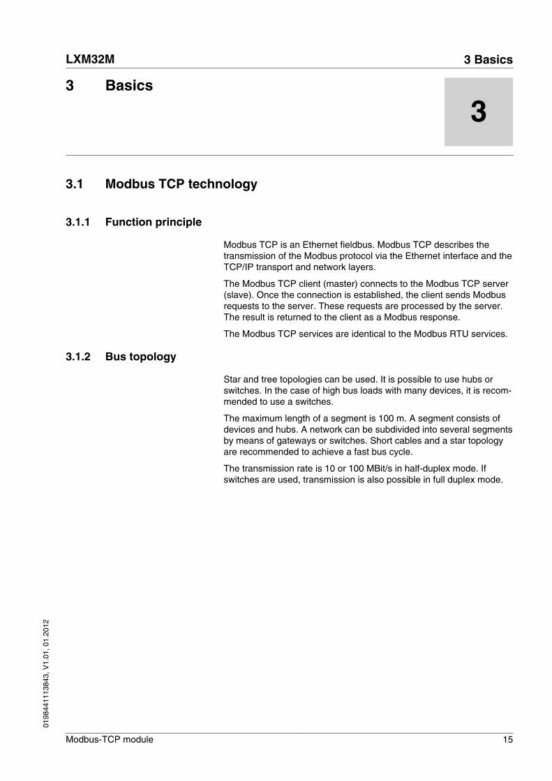
Modbus TCP is an Ethernet fieldbus. Modbus TCP describes thetransmission of the Modbus protocol via the Ethernet interface and theTCP/IP transport and network layers.
The Modbus TCP client (master) connects to the Modbus TCP server(slave). Once the connection is established, the client sends Modbusrequests to the server. These requests are processed by the server.The result is returned to the client as a Modbus response.
The Modbus TCP services are identical to the Modbus RTU services.
3.1.2 Bus topology
Star and tree topologies can be used. It is possible to use hubs orswitches. In the case of high bus loads with many devices, it is recom-mended to use a switches.
The maximum length of a segment is 100 m. A segment consists ofdevices and hubs. A network can be subdivided into several segmentsby means of gateways or switches. Short cables and a star topologyare recommended to achieve a fast bus cycle.
The transmission rate is 10 or 100 MBit/s in half-duplex mode. Ifswitches are used, transmission is also possible in full duplex mode.
LXM32M 3 Basics
Modbus-TCP module 15
0198
4411
1384
3, V
1.01
, 01.
2012

3.1.3 Client / server model
Modbus Client Modbus Server
Request Indication
ResponseConfirmation
Figure 2: Client / server model
The Modbus messaging service implements client/server communica-tion between devices connected by means of a TCP/IP network. Mod-bus TCP does not use an object dictionary.
The client/server model is based on 4 types of messages:
• Request: Message sent by the client to initiate a transaction.• Indication: Request as received by the server.• Response: Response message to the request sent by the server.• Confirmation: Response as received by the client.
A communication cycle consists of the request from the client (requestfrom the fieldbus master) and a response from the server (responsefrom the fieldbus slave). Modbus request and Modbus response havethe same structure. If an error occurs on receipt of the Modbusrequest or if the slave cannot execute the action, the slave sends anerror message in the Modbus response.
The product analyzes the Modus requests received. Depending on theModbus request, the product triggers actions or provides requesteddata.
3.1.4 Network service SNMP
The Internet community has developed the SNMP standard "SimpleNetwork Management Protocol" to support the management of differ-ent network devices by means of a single system.
The Network Management System can exchange data with SNMPdevices. The tasks of the network management system comprisemonitoring, control and configuration of network components as wellas error detection and error messaging.
SNMP agent ConneXview The product supports SNMP version 1.0. An SNMP agent must beused to monitor a network with SNMP. Schneider Electric offers thetool ConneXview for such purposes.
3 Basics LXM32M
16 Modbus-TCP module
0198
4411
1384
3, V
1.01
, 01.
2012

3.2 Modbus TCP protocol
The Modbus protocol defines a so-called Modbus PDU (Protocol DataUnit) which is independent of the underlying communication layers.This Modbus PDU consists of the fields "Function Code" and "Data".Depending on the mapping to the different network protocols, theModbus PDU is extended by additional fields in the so-called ModbusADU (Application Data Unit). The Modbus PDU and the Modbus ADUconstitute the Modbus message, also referred to as "Frame".
Function code DataMBAP Header
MODBUS PDU
MODBUS TCP/IP ADU
Figure 3: Structure of a Modbus message
The "Function Code" of a message specified the Modbus service to betriggered. The "Data" field can contain additional information, depend-ing on the "Function Code".
Due to the encapsulation of "Function Code" and "Data" in the Mod-bus PDU, the Modbus services and the object model can be the samein the case of all Modbus versions.
In the case of a "Function Code" for which the "Data" field in the Mod-bus PDU has a fixed length, the "Function Code" is sufficient.
In the case of a "Function Code" for which the "Data" field in the Mod-bus request or the Modbus response has a variable amount of data,the "Data" field contains a byte counter.
The maximum size of a Modbus ADU is 260 bytes. The size of anembedded Modbus PDU is 253 bytes.
NOTE: The fields are encoded in Big Endian format (highest-valuebyte first).
LXM32M 3 Basics
Modbus-TCP module 17
0198
4411
1384
3, V
1.01
, 01.
2012

3.2.1 MBAP header
The MBAP header contains the information allowing the recipient touniquely identify a message. This is even possible if a message is splitinto several packets for transmission.
Explicit and implicit length rules as well as the use of a CRC-32 errorcheck code (on Ethernet) results in an infinitesimal chance of undetec-ted corruption to a request or response message.
Design The MBAP header has a length of 7 bytes and contains the followingfields:
Field Length Description
Transaction Identifier 2 bytes Identification of a Modbusrequest or Modbus response.
Protocol Identifier 2 bytes Value 0 means Modbus proto-col.
Length 2 bytes Number of bytes to follow.
Unit Identifier 1 byte Identification of a slave con-nected to another bus via aserial line.
• Transaction Identifier
The field "Transaction Identifier" is used for "Pairing". The servercopies the "Transaction Identifier" of the Modbus request to theModbus response.
• Protocol Identifier
The field "Protocol Identifier" is used to identify the protocol. TheModbus protocol is identified by the value 0.
• Length
The "Length" field is a byte counter for the following fields ("UnitIdentifier", "Function Code" and "Data").
• Unit Identifier
The field "Unit Identifier" is used to identify the server in the slave.
3 Basics LXM32M
18 Modbus-TCP module
0198
4411
1384
3, V
1.01
, 01.
2012

3.3 Modbus TCP communication
3.3.1 Connection management
Establishing of a connection The Modbus TCP server allows for TCP connections via the defaultport 502. A client can establish a new connection via this port. If theclient is to exchange data with a remote server, a new client connec-tion via remote port 502 must be established.
Modbus data transfer A Modbus request is sent via a suitable, open connection. This TCPconnection is found using the IP address of the remote device. Theconnection remains open for all Modbus communication. Up to 8simultaneous connections are possible.
As described in the next chapter, a Modbus client can initialize severalModbus transactions without having to wait for the previous transac-tion to be finished.
Closing a connection After the Modbus communication between the client and a server isfinished, the client causes the connection used to be closed.
The server does not close the connection under normal circumstan-ces.
However, when errors occur and in special cases, the server closesthe connection, for example:
• Communication errors• Communication inactivity• Maximum number of connections reached
The product can manage up to 8 TCP connections. If an attempt ismade to establish a further connection beyond this maximum, the old-est unused connection is closed. If it is impossible to close the oldestunused connection, the new connection is refused.
LXM32M 3 Basics
Modbus-TCP module 19
0198
4411
1384
3, V
1.01
, 01.
2012
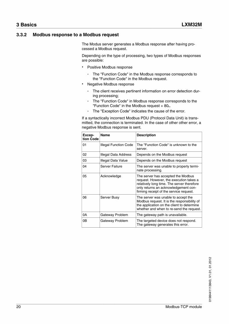
3.3.2 Modbus response to a Modbus request
The Modus server generates a Modbus response after having pro-cessed a Modbus request.
Depending on the type of processing, two types of Modbus responsesare possible:
• Positive Modbus response
- The "Function Code" in the Modbus response corresponds tothe "Function Code" in the Modbus request.
• Negative Modbus response
- The client receives pertinent information on error detection dur-ing processing;
- The "Function Code" in Modbus response corresponds to the"Function Code" in the Modbus request + 80h.
- The "Exception Code" indicates the cause of the error.
If a syntactically incorrect Modbus PDU (Protocol Data Unit) is trans-mitted, the connection is terminated. In the case of other other error, anegative Modbus response is sent.
Excep-tion Code
Name Description
01 Illegal Function Code The "Function Code" is unknown to theserver.
02 Illegal Data Address Depends on the Modbus request
03 Illegal Data Value Depends on the Modbus request
04 Server Failure The server was unable to properly termi-nate processing.
05 Acknowledge The server has accepted the Modbusrequest. However, the execution takes arelatively long time. The server thereforeonly returns an acknowledgement con-firming receipt of the service request.
06 Server Busy The server was unable to accept theModbus request. It is the responsibility ofthe application on the client to determinewhether and when to re-send the request.
0A Gateway Problem The gateway path is unavailable.
0B Gateway Problem The targeted device does not respond.The gateway generates this error.
3 Basics LXM32M
20 Modbus-TCP module
0198
4411
1384
3, V
1.01
, 01.
2012

3.3.3 Reading and writing parameters
Parameters are processed as 32 bit values. 16 bit values must also beprocessed as 32 bit values. Two consecutive 16 bit parameters mustbe read or written to process a 16 bit parameter. The first Modbusaddress must be specified.
If several consecutive parameters are to be processed, a single Mod-bus command with the corresponding Modbus address and the lengthindication is sufficient.
NOTE: This does not apply to reading and writing parameters withaddresses in the range from 17408 (4400h) to 17663 (44FFh). In thisrange, only a single parameter can be addressed with one Modbuscommand.
Example Reading the parameter CTRL1_KPp "Position controller P gain"Modbus address 4614
When the parameter CTRL1_KPp with the Modbus parameter address4614 and length 2 is read, the two parameter addresses 4614 and4615 are read. Result:
Address Value
4614 0000h
4615 00C8h
LXM32M 3 Basics
Modbus-TCP module 21
0198
4411
1384
3, V
1.01
, 01.
2012

3.3.4 I/O scanning to "Drive Profile Lexium"
I/O scanning is used for cyclic interchange of data between masterand slave.
I/O scanning must be configured on the master. The master can use 2different approaches for of I/O scanning:
• "Function Code" 23 (17h), Read-Write Mulitple Registers• "Function Code" 3 (03h), Read Multiple Registers and "Function
Code" 16 (10h), Write Multiple Registers
NOTE: The read value is 0 until the first write command is execu-ted.
Settings The following setting must be made on the master before you can useI/O scanning:
• The "Unit Identifier" is 255.• The Modbus parameter address is 0.• The data length is 13.
In addition, you can use up to 3 mappable parameters. If theseparameters are used, the data length changes to 15, 17 or 19.
The Modbus addresses for I/O scanning do not differ from theaddresses for normal Modbus access.
Output - Input Output and input refer to the direction of data transmission from theperspective of the master.
• Output: Commands from the master to the slave• Input: Status messages from the slave to the master
3 Basics LXM32M
22 Modbus-TCP module
0198
4411
1384
3, V
1.01
, 01.
2012

3.3.4.1 I/O scanning Output
The table below shows the structure of the cyclic data for the com-mands from the master to the product. See the product manual for adescription of the parameters.
Byte Meaning Data type Parameter address
0 ... 7 ParCh - Parameter channel
8 ... 9 dmControl INT -
10 ... 13 RefA32 DINT -
14 ... 17 RefB32 DINT -
18 ... 21 Ramp_v_acc DINT Parameter Ramp_v_acc Modbus 1556
22 ... 25 Ramp_v_dec DINT Parameter Ramp_v_dec Modbus 1558
26 ... 29 EthOptMapOut1 DINT Parameter EthOptMapOut1 Modbus 17500
30 ... 33 EthOptMapOut2 DINT Parameter EthOptMapOut2 Modbus 17502
34 ... 37 EthOptMapOut3 DINT Parameter EthOptMapOut3 Modbus 17504
ParCh Parameters can be read or written via "ParCh", see chapter"3.3.4.3 Parameter channel".
dmControl The word "dmControl" is used to set the operating state and the oper-ating mode.
See chapters "6.1.2 Changing the operating state" and"6.2.2 Starting and changing an operating mode" for a detaileddescription of the bits.
RefA32, RefB32 The two double words "RefA32" and "RefB32" are used to set two val-ues for the operating mode. The meaning depends on the operatingmode; it is described in the chapters on the individual operatingmodes.
Ramp_v_acc / Ramp_v_dec The double words "Ramp_v_acc" and "Ramp_v_dec" are used to setthe acceleration and the deceleration. They correspond to the param-eters of the same name. See the product manual for a description.
EthOptMapOut1 ... EthOptMap-Out3
The double words EthOptMapOut1 ... EthOptMapOut3 contain select-able parameters, see chapter"5.7.3 Setting the mapping for I/O scanning".
LXM32M 3 Basics
Modbus-TCP module 23
0198
4411
1384
3, V
1.01
, 01.
2012

3.3.4.2 I/O scanning Input
The table below shows the structure of the cyclic data for the statusmessages from the product to the master. See the product manual fora description of the parameters.
Byte Meaning Data type Parameter address
0 ... 7 ParCh - Parameter channel
8 ... 9 driveStat INT -
10 ... 11 mfStat INT -
12 ... 13 motionStat INT -
14 ... 15 driveInput INT -
16 ... 19 _p_act DINT Parameter _p_act Modbus 7706
20 ... 23 _v_act DINT Parameter _v_act Modbus 7744
24 ... 25 _I_act INT Parameter _I_act Modbus 7686
26 ... 29 EthOptMapInp1 DINT Parameter EthOptMapInp1 Modbus 17512
30 ... 33 EthOptMapInp2 DINT Parameter EthOptMapInp2 Modbus 17514
34 ... 37 EthOptMapInp3 DINT Parameter EthOptMapInp3 Modbus 17516
ParCh Parameters can be read or written via "ParCh", see chapter"3.3.4.3 Parameter channel".
driveStat The current operating state is indicated with the "driveStat" word.
For a detailed description of the bits, see chapter"6.1.1 Indication of the operating state".
mfStat The word "mfStat" is used to indicate the current operating mode.
For a detailed description of the bits, see chapter"6.2.1 Indicating and monitoring the operating mode".
motionStat The word "motionStat" is used to provide information on the motor andprofile generator.
bit Meaning
0 ... 5 Reserved
6 MOTZ: Motor at a standstill
7 MOTP: Motor movement in positive direction
8 MOTN: Motor movement in negative direction
9 PWIN: Motor within position window
10 Reserved
11 TAR0: Profile generator at standstill
12 DEC: Profile generator decelerates
13 ACC: Profile generator accelerates
14 CNST: Profile generator moves at constant velocity
15 Reserved
3 Basics LXM32M
24 Modbus-TCP module
0198
4411
1384
3, V
1.01
, 01.
2012
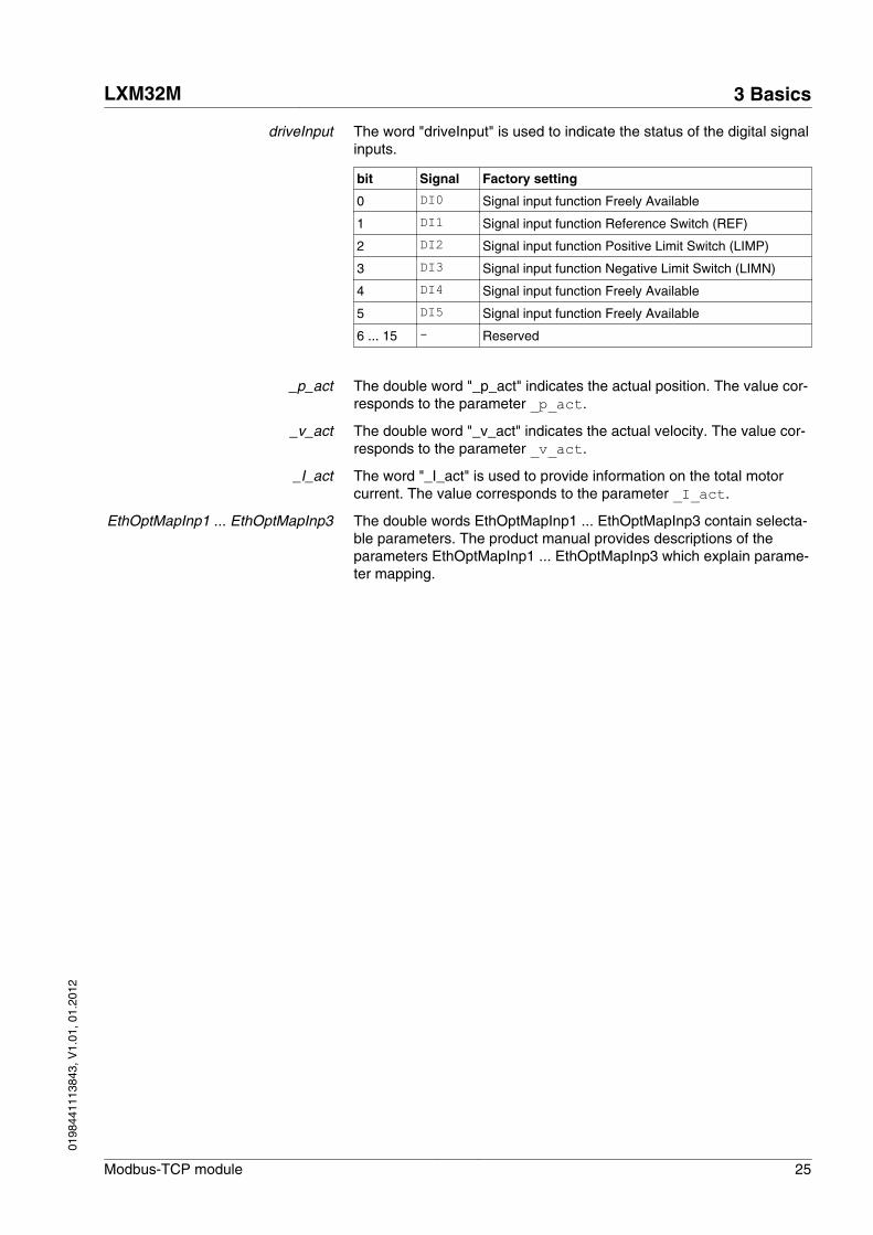
driveInput The word "driveInput" is used to indicate the status of the digital signalinputs.
bit Signal Factory setting
0 DI0 Signal input function Freely Available
1 DI1 Signal input function Reference Switch (REF)
2 DI2 Signal input function Positive Limit Switch (LIMP)
3 DI3 Signal input function Negative Limit Switch (LIMN)
4 DI4 Signal input function Freely Available
5 DI5 Signal input function Freely Available
6 ... 15 - Reserved
_p_act The double word "_p_act" indicates the actual position. The value cor-responds to the parameter _p_act.
_v_act The double word "_v_act" indicates the actual velocity. The value cor-responds to the parameter _v_act.
_I_act The word "_I_act" is used to provide information on the total motorcurrent. The value corresponds to the parameter _I_act.
EthOptMapInp1 ... EthOptMapInp3 The double words EthOptMapInp1 ... EthOptMapInp3 contain selecta-ble parameters. The product manual provides descriptions of theparameters EthOptMapInp1 ... EthOptMapInp3 which explain parame-ter mapping.
LXM32M 3 Basics
Modbus-TCP module 25
0198
4411
1384
3, V
1.01
, 01.
2012

3.3.4.3 Parameter channel
The master can request a parameter value from the slave or change aparameter value via the parameter channel. Each parameter can beuniquely addressed via the index and subindex.
76543210Byte
CtrlSubindex
IndexPV
Figure 4: Parameter channel
Ctrl Byte "Ctrl" contains the request to read or write a parameter.
The transmit data contains the information whether a parameter is tobe read or written. The receive data contains the information whetherthe read request or the write request were successful.
Transmit data:
Ctrl Function
02h No request
12h Read request
22h Write request (word)
32h Write request (double word)
Receive data:
Ctrl Function
02h Request not yet completed
12h Read request or write request successfully completed (word)
22h Read request or write request successfully completed (doubleword)
72h Error message
Only one request can be processed at a time. The slave provides theresponse until the master sends a new request. If a response includesparameter values, the slave responds with the current value in thecase of a repetition.
NOTE: Read requests are only executed by the slave if the valuechanges from 02h to 12h. Write requests requests are only executedby the slave if the value changes from 02h to 22h or to 32h.
Subindex The byte "Subindex" must be set to the value 00h.
Index The word "Index" contains the parameter address.
See the product manual for a list of the parameters.
3 Basics LXM32M
26 Modbus-TCP module
0198
4411
1384
3, V
1.01
, 01.
2012

PV The double word "PV" contains the parameter value.
In the case of a read request, the value in the transmit data has nosignificance. The receive data contains the parameter value.
In the case of a write request, the transmit data contains the value tobe written to the parameter. The receive data contains the parametervalue.
If a read request or a write request were not successful, the doubleword "PV" contains the error number of the error.
Example: Reading a parameter In the example, the program number of the product is read from theparameter _prgNoDEV. The parameter _prgNoDEV has the parame-ter address 258 (01h 02h).
The parameter value read has the decimal value 91200 which corre-sponds to 01h 64h 40h.
Transmit data:
Ctrl Subindex Index PV
12h 00h 01h 02h 00h 00h 00h 00h
Receive data:
Ctrl Subindex Index PV
22h 00 h 01h 02h 00h 01h 64h 40h
Example: Writing of an invalidparameter
In this example, the value of a non-existent parameter is to bechanged. The parameter has the parameter address 101 (00h 65h).The value of the parameters is to be changed to 222 (DEh).
Before the slave can accept a new request, the value 02h must first betransmitted in byte "Ctrl".
Since the slave cannot address the parameter, a synchronous errormessage is transmitted with the receive data. Byte "Ctrl" is set to 72h.Double word "PV" is set to the error number (error number 1101h:Parameter does not exist).
Transmit data:
Ctrl Subindex Index PV
32h 00h 00h 65h 00h 00h 00h DEh
Receive data:
Ctrl Subindex Index PV
72h 00h 00h 65h 00h 00h 11h 01h
See the product manual for information on the error numbers.
LXM32M 3 Basics
Modbus-TCP module 27
0198
4411
1384
3, V
1.01
, 01.
2012

3.4 Modbus services - "Function Code"
The table below provides an overview of the available Modbus serv-ices:
"FunctionCode"
Meaning under Modbus Meaning from device per-spective
3 Read Multiple Registers Reading a parameter
8 Diagnostics Diagnostics
16 Write Multiple Registers Writing a parameter
23 Read/Write Multiple Registers Reading and writing parame-ters
43Subcode14
Read Device Identification –
90 UMAS File Transfer (Upload) –
3.4.1 "Function Code" 3 (Read Multiple Registers)
This "Function Code" 3 (Read Multiple Registers) allows you to readseveral consecutive parameters, starting at any address.
Modbus request Structure of the Modbus request:
Field Bytes Value Meaning
Function Code 1 3 = 03h Read Multiple Registers
Starting Address 2 (various) Address of the first parameter to be read
Quantity Of Regis-ters
2 2 * n Number of 16 bit values to be read(1 parameter has the value 2 since a parameterconsists of a 32 bit value)
Modbus response Structure of the positive Modbus response:
Field Bytes Value Meaning
Function Code 1 3 = 03h Read Multiple Registers
Byte Count 1 4 * n Number of data bytes
Registers Value 4 * n (various) Parameter values
Structure of the negative Modbus response
Field Bytes Value Meaning
Function Code 1 03h + 80h = 83h Read Multiple Registers
Exception Code 1 01h ... 04h See chapter"3.3.2 Modbus response to a Modbus request"
3 Basics LXM32M
28 Modbus-TCP module
0198
4411
1384
3, V
1.01
, 01.
2012

3.4.2 "Function Code" 8 (Diagnostics)
This "Function Code" 8 (Diagnostics) allows you to read diagnosticsdata of the slave.
Modbus request Structure of the Modbus request:
Field Bytes Value Meaning
Function Code 1 8 = 08h Diagnostics
Sub-function Code 2 (various) Diagnostics function
Data 2 (various) Data (depending on diagnostics function)
Modbus response Structure of the positive Modbus response:
Field Bytes Value Meaning
Function Code 1 8 = 08h Diagnostics
Sub-function Code 2 (various) Diagnostics function
Data 2 (various) Diagnostics data
Structure of the negative Modbus response
Field Bytes Value Meaning
Function Code 1 08h + 80h = 88h Diagnostics
Exception Code 1 01h ... 04h See chapter"3.3.2 Modbus response to a Modbus request"
Sub-function Code The following diagnostics functions are available:
Sub-function Code Diagnostics function
00 Return Query Data Return request as a response
01 Restart Communication Option Re-initialize the communication port
02 Return Diagnostic Register Return the error number in the case of synchronous errors
03 (reserved) –
04 Force Listen Only Mode Force "Listen Only" mode
05 ... 09 (reserved) –
10 Clear Counters and DiagnosticRegister
Clear all statistical counters
11 Return Bus Message Count Return number of detected "Bus Message"s
12 Return Bus CommunicationError Count
Return number of detected "Bus Communication Error"s
13 Return Bus Exception ErrorCount
Return number of detected "Bus Exception Error"s
14 ... 15 (reserved) –
16 Return Slave NAK Count Return number of detected "Slave Not-Acknowledged"s
17 Return Slave Busy Count Return number of detected "Slave Busy"s
18 Return Bus Char OverrunCount
Return number of detected "Bus Char Overrun"s
>18 (reserved) –
LXM32M 3 Basics
Modbus-TCP module 29
0198
4411
1384
3, V
1.01
, 01.
2012
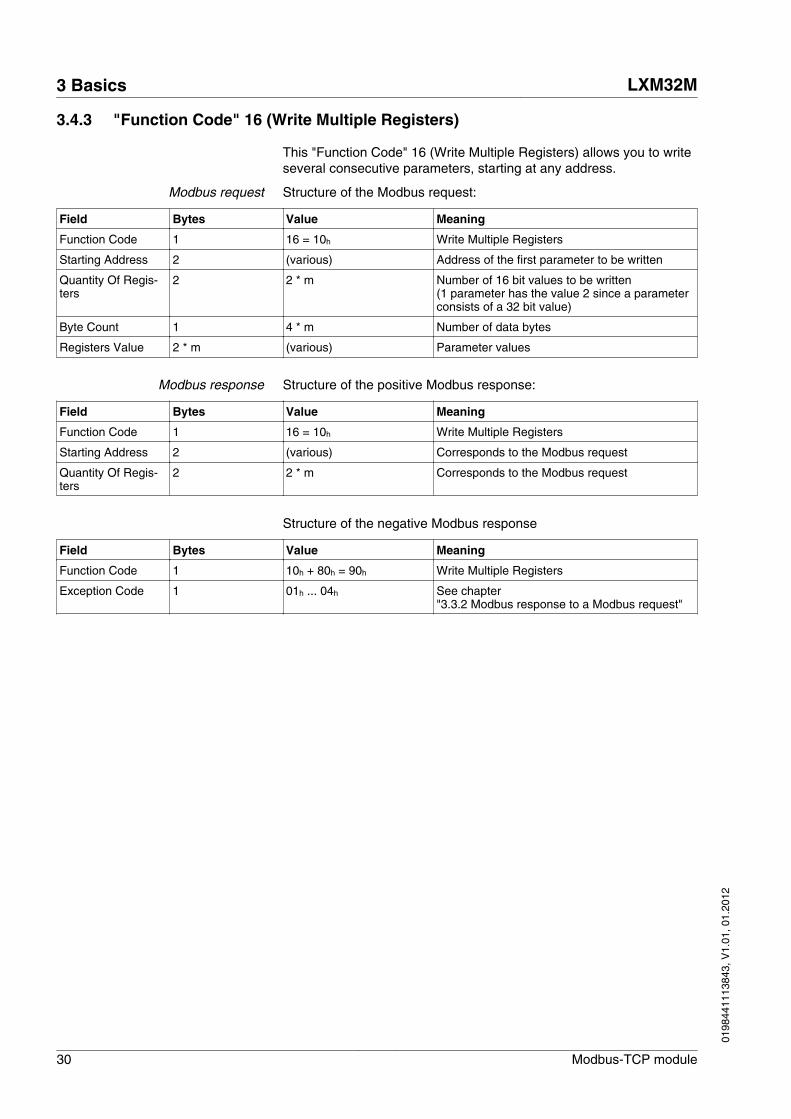
3.4.3 "Function Code" 16 (Write Multiple Registers)
This "Function Code" 16 (Write Multiple Registers) allows you to writeseveral consecutive parameters, starting at any address.
Modbus request Structure of the Modbus request:
Field Bytes Value Meaning
Function Code 1 16 = 10h Write Multiple Registers
Starting Address 2 (various) Address of the first parameter to be written
Quantity Of Regis-ters
2 2 * m Number of 16 bit values to be written(1 parameter has the value 2 since a parameterconsists of a 32 bit value)
Byte Count 1 4 * m Number of data bytes
Registers Value 2 * m (various) Parameter values
Modbus response Structure of the positive Modbus response:
Field Bytes Value Meaning
Function Code 1 16 = 10h Write Multiple Registers
Starting Address 2 (various) Corresponds to the Modbus request
Quantity Of Regis-ters
2 2 * m Corresponds to the Modbus request
Structure of the negative Modbus response
Field Bytes Value Meaning
Function Code 1 10h + 80h = 90h Write Multiple Registers
Exception Code 1 01h ... 04h See chapter"3.3.2 Modbus response to a Modbus request"
3 Basics LXM32M
30 Modbus-TCP module
0198
4411
1384
3, V
1.01
, 01.
2012
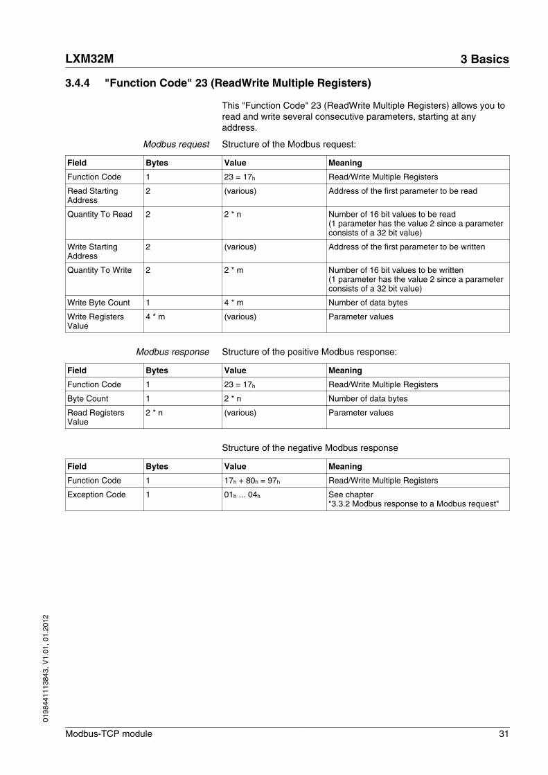
3.4.4 "Function Code" 23 (ReadWrite Multiple Registers)
This "Function Code" 23 (ReadWrite Multiple Registers) allows you toread and write several consecutive parameters, starting at anyaddress.
Modbus request Structure of the Modbus request:
Field Bytes Value Meaning
Function Code 1 23 = 17h Read/Write Multiple Registers
Read StartingAddress
2 (various) Address of the first parameter to be read
Quantity To Read 2 2 * n Number of 16 bit values to be read(1 parameter has the value 2 since a parameterconsists of a 32 bit value)
Write StartingAddress
2 (various) Address of the first parameter to be written
Quantity To Write 2 2 * m Number of 16 bit values to be written(1 parameter has the value 2 since a parameterconsists of a 32 bit value)
Write Byte Count 1 4 * m Number of data bytes
Write RegistersValue
4 * m (various) Parameter values
Modbus response Structure of the positive Modbus response:
Field Bytes Value Meaning
Function Code 1 23 = 17h Read/Write Multiple Registers
Byte Count 1 2 * n Number of data bytes
Read RegistersValue
2 * n (various) Parameter values
Structure of the negative Modbus response
Field Bytes Value Meaning
Function Code 1 17h + 80h = 97h Read/Write Multiple Registers
Exception Code 1 01h ... 04h See chapter"3.3.2 Modbus response to a Modbus request"
LXM32M 3 Basics
Modbus-TCP module 31
0198
4411
1384
3, V
1.01
, 01.
2012

3.4.5 "Function Code" 43 (Encapsulated Interface Transport)
This "Function Code" 43 / 14 (Read Device Identification) allows youto read device-specific data.
Modbus request Structure of the Modbus request:
Field Bytes Value Meaning
Function Code 1 43 = 2Bh Encapsulated Interface Transport
Modbus Encapsula-ted Interface Type
1 14 = 0Eh Fixed value 14 (Read Device Identification)
Read Device IDCode
1 01 Read all objects
Object ID 1 0x00 Object ID
Modbus response Structure of the positive Modbus response:
Field Bytes Value Meaning
Function Code 1 43 = 2Bh Encapsulated Interface Transport
Modbus Encapsula-ted Interface Type
1 14 = 0Eh Fixed value 14 (Read Device Identification)
Read Device IDCode
1 01 Corresponds to the Modbus request
Conformity Level 1 02 Fixed value
More Follows 1 00 Fixed value
Next Object ID 1 00 Fixed value
Number Of Objects 1 03 Number of objects
Object ID 1 Object ID, see table
Object Length 1 Object length
Object Value (various) Object data (various)
Structure of the negative Modbus response
Field Bytes Value Meaning
Function Code 1 2Bh + 80h = ABh Encapsulated Interface Transport
Exception Code 1 01h ... 04h See chapter"3.3.2 Modbus response to a Modbus request"
Object ID The following object IDs are available:
Object ID Object name Value
00h vendor name Manufacturer name
01h product code „xxxxxxxxxxxx“ (see type code)
03h revision "Vxx.yyy" (e.g. "V02.001")
3 Basics LXM32M
32 Modbus-TCP module
0198
4411
1384
3, V
1.01
, 01.
2012

3.4.6 Examples
3.4.6.1 Example of "Function Code" 3
Reading an error memory entry. Since the Modbus addresses of theparameters of an error memory entry are contiguous (ascendingorder), a single Modbus request is sufficient.
Parameters _ERR_number (15362), _ERR_class (15364),_ERR_time (15366) and _ERR_qual (15368).
Modbus request Structure of the Modbus request:
Field Bytes Value Meaning
Function Code 1 3 Read Multiple Registers
Starting Address 2 15362 (3C02h) Address of the first parameter to be read
Quantity Of Regis-ters
2 8 Number of the 16 bit values to be read = 8
Modbus response Structure of the positive Modbus response:
Field Bytes Value Meaning
Function Code 1 3 Read Multiple Registers
Byte Count 1 16 Number of bytes: 8 bytes of data
Registers Value 16 32 bit value32 bit value32 bit value32 bit value
_ERR_number, 15362 (error number)_ERR_class, 15364 (error class)_ERR_time, 15366 (error time)_ERR_qual, 15368 (error qualifier)
3.4.6.2 Example of "Function Code" 16
Writing of the software limit switches. Since these parameters alsohave consecutive addresses, a single Modbus request is sufficient:
Parameters MON_swLimP (1544) and MON_swLimN (1546).
Modbus request Structure of the Modbus request:
Field Bytes Value Meaning
Function Code 1 16 Write Multiple Registers
Starting Address 2 1544 (608h) Address of the first parameter to be written
Quantity Of Regis-ters
2 4 Number of parameters = 4 (8 bytes of data)
Byte Count 1 8 Number of bytes: 8 bytes of data
Registers Value 8 32 bit value32 bit value
MON_swLimP, 1544MON_swLimN, 1546
Modbus response Structure of the positive Modbus response:
Field Bytes Value Meaning
Function Code 1 16 Write Multiple Registers
Starting Address 2 1544 (608h) Address of the parameter
Quantity Of Regis-ters
2 4 Number of parameters = 4 (8 bytes of data)
LXM32M 3 Basics
Modbus-TCP module 33
0198
4411
1384
3, V
1.01
, 01.
2012

3 Basics LXM32M
34 Modbus-TCP module
0198
4411
1384
3, V
1.01
, 01.
2012
4 Installation
4
WARNINGSIGNAL AND DEVICE INTERFERENCE
Signal interference can cause unexpected responses of the device.
• Install the wiring in accordance with the EMC requirements.• Verify compliance with the EMC requirements.
Failure to follow these instructions can result in death, seriousinjury or equipment damage.
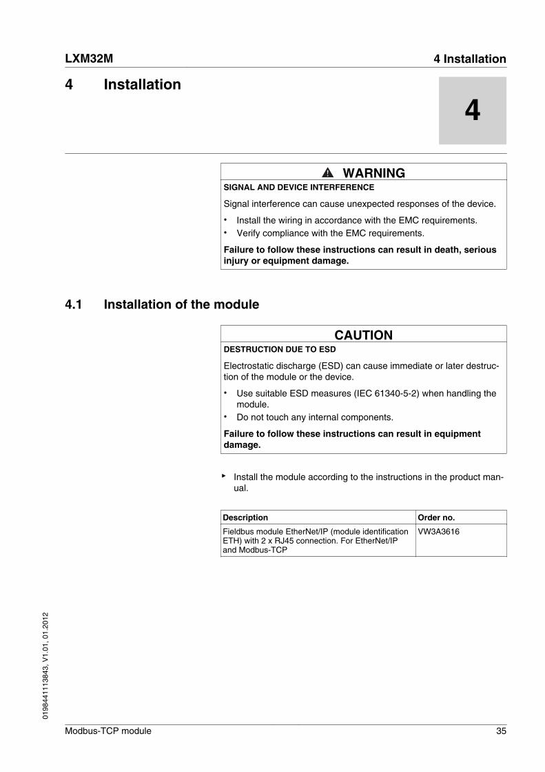
4.1 Installation of the module
CAUTIONDESTRUCTION DUE TO ESD
Electrostatic discharge (ESD) can cause immediate or later destruc-tion of the module or the device.
• Use suitable ESD measures (IEC 61340-5-2) when handling themodule.
• Do not touch any internal components.
Failure to follow these instructions can result in equipmentdamage.
▶ Install the module according to the instructions in the product man-ual.
Description Order no.
Fieldbus module EtherNet/IP (module identificationETH) with 2 x RJ45 connection. For EtherNet/IPand Modbus-TCP
VW3A3616
LXM32M 4 Installation
Modbus-TCP module 35
0198
4411
1384
3, V
1.01
, 01.
2012

4.2 Electrical installation
Cable specificationsShield: Required, both ends grounded
Twisted Pair: Required
PELV: Required
Cable composition: 8 * 0.25 mm2 (8 * AWG 22)
Maximum cable length: 100 m
Special features: -
▶ Note the pertinent information on equipotential bonding conductorsin the product manual.
▶ Use pre-assembled cables to reduce the risk of wiring errors.
Pin assignment
Slot 3
12345678
12345678
1
8
1
8
A
B
A
B
Figure 5: Pin assignment
Pin Signal Meaning
1 Tx+ Ethernet transmit signal +
2 Tx- Ethernet transmit signal -
3 Rx+ Ethernet receive signal +
4 - -
5 - -
6 Rx- Ethernet receive signal -
7 - -
8 - -
4 Installation LXM32M
36 Modbus-TCP module
0198
4411
1384
3, V
1.01
, 01.
2012

5 Commissioning
5
WARNINGLOSS OF CONTROL
The product is unable to detect an interruption of the network link ifconnection monitoring is not active.
• Verify that connection monitoring is on.• The shorter the time for monitoring, the faster the detection of the
interruption.
Failure to follow these instructions can result in death, seriousinjury or equipment damage.
WARNINGUNINTENDED OPERATION
• Do not write values to reserved parameters.• Do not write values to parameters unless you fully understand the
function.• Run initial tests without coupled loads.• Verify the use of the word sequence with fieldbus communication.• Do not establish a fieldbus connection unless you have fully
understood the communication principles.• Only start the system if there are no persons or obstructions in
the hazardous area.
Failure to follow these instructions can result in death, seriousinjury or equipment damage.
5.1 Commissioning the device
For installation in the network, the device must first be properly instal-led (mechanically and electrically) and commissioned.
▶ Commission the device as per product manual.
LXM32M 5 Commissioning
Modbus-TCP module 37
0198
4411
1384
3, V
1.01
, 01.
2012
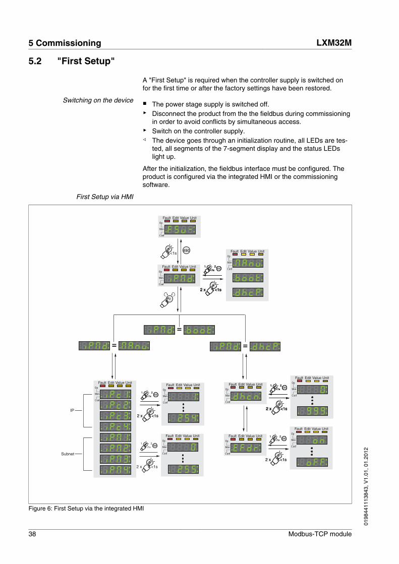
5.2 "First Setup"
A "First Setup" is required when the controller supply is switched onfor the first time or after the factory settings have been restored.
Switching on the device ■ The power stage supply is switched off.▶ Disconnect the product from the the fieldbus during commissioning
in order to avoid conflicts by simultaneous access.▶ Switch on the controller supply.◁ The device goes through an initialization routine, all LEDs are tes-
ted, all segments of the 7-segment display and the status LEDslight up.
After the initialization, the fieldbus interface must be configured. Theproduct is configured via the integrated HMI or the commissioningsoftware.
First Setup via HMI
Fault Edit Value UnitOp
Mon
Conf
Fault Edit Value UnitOp
Mon
Conf
<1sESC Fault Edit Value Unit
Op
Mon
Conf
Fault Edit Value UnitOp
Mon
Conf
IP
Subnet
<1s2 x
<1sESC
1. 2.
<1s2 x
<1sESC
1. 2.
<1s2 x
<1sESC
1. 2.
<1s2 x
<1sESC
1. 2.
Fault Edit Value UnitOp
Mon
Conf
Fault Edit Value UnitOp
Mon
Conf
Fault Edit Value UnitOp
Mon
Conf
Fault Edit Value UnitOp
Mon
Conf
Fault Edit Value UnitOp
Mon
Conf
<1s2 x
<1sESC
1. 2.
Fault Edit Value UnitOp
Mon
Conf
Fault Edit Value UnitOp
Mon
Conf
<1s2 x
<1sESC
1. 2.
<1s2 x
<1sESC
1. 2.
<1s2 x
<1sESC
1. 2.
<1s2 x
<1sESC
1. 2.
Fault Edit Value UnitOp
Mon
Conf
<1s2 x
<1sESC
1. 2.
Fault Edit Value UnitOp
Mon
Conf
<1s2 x
<1sESC
1. 2.
Fault Edit Value UnitOp
Mon
Conf
<1s2 x
<1sESC
1. 2.
Fault Edit Value UnitOp
Mon
Conf
<1s2 x
<1sESC
1. 2.
=
=
=
Figure 6: First Setup via the integrated HMI
5 Commissioning LXM32M
38 Modbus-TCP module
0198
4411
1384
3, V
1.01
, 01.
2012

Type of network address assign-ment
▶ Select the type of network address assignment.
The type of network address assignment is set via the parameterEthIpMode (iPMd).
Parameter nameHMI menuHMI name
Description UnitMinimum valueFactory settingMaximum value
Data typeR/WPersistentExpert
Parameter addressvia fieldbus
EthIpModeConF → CoM- ConF → FSu-
iPMd
Type of obtaining IP address
0 / Manual / MAnu : Manual1 / BOOTP / boot : BOOTP2 / DHCP / dhcP : DHCP
When selecting DHCP, also set the parame-ter EthFdrEnable to ON or OFF, dependingon whether or not your DHCP server sup-ports FDR.
Changed settings become active immedi-ately.
-022
UINT16UINT16UINT16UINT16 R/Wper.-
CANopen 3044:5h Modbus 17418Profibus 17418CIP 168.1.5
5.2.1 Manual assignment of the network address
■ EthIpMode has been set to Manual (manu).▶ Set the network addresses consisting of the IP address and the
subnet mask.
The IP address is set via the parametersEthIPmodule1 ... EthIPmodule4. The subnet mask is set viathe parameters EthIPmask1 ... EthIPmask4.
LXM32M 5 Commissioning
Modbus-TCP module 39
0198
4411
1384
3, V
1.01
, 01.
2012

Parameter nameHMI menuHMI name
Description UnitMinimum valueFactory settingMaximum value
Data typeR/WPersistentExpert
Parameter addressvia fieldbus
EthIPmodule1ConF → CoM- ConF → FSu-
iPc1
IP address Ethernet module, byte 1
Changed settings become active the nexttime the product is switched on.
-00255
UINT16UINT16UINT16UINT16 R/Wper.-
CANopen 3044:7h Modbus 17422Profibus 17422CIP 168.1.7
EthIPmodule2ConF → CoM- ConF → FSu-
iPc2
IP address Ethernet module, byte 2
Changed settings become active the nexttime the product is switched on.
-00255
UINT16UINT16UINT16UINT16 R/Wper.-
CANopen 3044:8h Modbus 17424Profibus 17424CIP 168.1.8
EthIPmodule3ConF → CoM- ConF → FSu-
iPc3
IP address Ethernet module, byte 3
Changed settings become active the nexttime the product is switched on.
-00255
UINT16UINT16UINT16UINT16 R/Wper.-
CANopen 3044:9h Modbus 17426Profibus 17426CIP 168.1.9
EthIPmodule4ConF → CoM- ConF → FSu-
iPc4
IP address Ethernet module, byte 4
Changed settings become active the nexttime the product is switched on.
-00255
UINT16UINT16UINT16UINT16 R/Wper.-
CANopen 3044:Ah Modbus 17428Profibus 17428CIP 168.1.10
EthIPmask1ConF → CoM- ConF → FSu-
iPM1
IP address subnet mask, byte 1
Changed settings become active the nexttime the product is switched on.
-0255255
UINT16UINT16UINT16UINT16 R/Wper.-
CANopen 3044:Bh Modbus 17430Profibus 17430CIP 168.1.11
EthIPmask2ConF → CoM- ConF → FSu-
iPM2
IP address subnet mask, byte 2
Changed settings become active the nexttime the product is switched on.
-0255255
UINT16UINT16UINT16UINT16 R/Wper.-
CANopen 3044:Ch Modbus 17432Profibus 17432CIP 168.1.12
EthIPmask3ConF → CoM- ConF → FSu-
iPM3
IP address subnet mask, byte 3
Changed settings become active the nexttime the product is switched on.
-0255255
UINT16UINT16UINT16UINT16 R/Wper.-
CANopen 3044:Dh Modbus 17434Profibus 17434CIP 168.1.13
EthIPmask4ConF → CoM- ConF → FSu-
iPM4
IP address subnet mask, byte 4
Changed settings become active the nexttime the product is switched on.
-00255
UINT16UINT16UINT16UINT16 R/Wper.-
CANopen 3044:Eh Modbus 17436Profibus 17436CIP 168.1.14
5 Commissioning LXM32M
40 Modbus-TCP module
0198
4411
1384
3, V
1.01
, 01.
2012

5.2.2 Assignment of the network address via BOOTP
■ EthIpMode has been set to BOOTP (boot).▶ Verify that an accessible BOOTP server is available on the net-
work.
LXM32M 5 Commissioning
Modbus-TCP module 41
0198
4411
1384
3, V
1.01
, 01.
2012

5.2.3 Assignment of the network address via DHCP
■ EthIpMode has been set to DHCP (dhcp).▶ Verify that an accessible DHCP server is available on the network.▶ Set a number that is unique in the network via dhcn.
NOTE: This setting is only required if you want to use an FDRserver.
The number is entered at the 13th, 14th and 15th digit of thedevice name.Example: LEXIUM_SERVO001
In the commissioning software, the full device name can be dis-played and changed.
▶ Activate the FDR service via EFdr.
See chapter "6.3.3 FDR service (Fast Device Replacement)" foradditional information on the FDR service.
Parameter nameHMI menuHMI name
Description UnitMinimum valueFactory settingMaximum value
Data typeR/WPersistentExpert
Parameter addressvia fieldbus
EthFdrEnableConF → CoM- ConF → FSu-
EFdr
FDR service
0 / Off / oFF : FDR service disabled1 / On / on : FDR service enabled
Enable Ethernet service "Fast DeviceReplacement" (FDR).If FDR is enabled, the DHCP server mustsupport FDR, otherwise no IP address canbe obtained via DHCP.
-001
UINT16UINT16UINT16UINT16 R/Wper.-
CANopen 3044:40h Modbus 17536Profibus 17536CIP 168.1.64
5 Commissioning LXM32M
42 Modbus-TCP module
0198
4411
1384
3, V
1.01
, 01.
2012

5.3 Setting the transmission rate
The parameter EthRateSet lets you set the transmission rate.
▶ Set the desired transmission rate with the parameter EthRateSet.
Parameter nameHMI menuHMI name
Description UnitMinimum valueFactory settingMaximum value
Data typeR/WPersistentExpert
Parameter addressvia fieldbus
EthRateSet Transmission rate setting
0 / Autodetect: Autodetect1 / 10 Mbps Full: 10 Mbps full duplex2 / 10 Mbps Half: 10 Mbps half duplex3 / 100 Mbps Full: 100 Mbps full duplex4 / 100 Mbps Half: 100 Mbps half duplex
Changed settings become active immedi-ately.
-004
UINT16UINT16UINT16UINT16 R/Wper.-
CANopen 3044:2h Modbus 17412Profibus 17412CIP 168.1.2
5.4 Setting the protocol
The protocol is set by means of the parameter EthMode.
▶ Set the parameter EthMode to "Modbus TCP".
Parameter nameHMI menuHMI name
Description UnitMinimum valueFactory settingMaximum value
Data typeR/WPersistentExpert
Parameter addressvia fieldbus
EthModeConF → CoM-
EtMd
Protocol
0 / Modbus TCP / MtCP : Modbus TCP I/Oscanning is enabled1 / EtherNet/IP / EtiP : EtherNet/IP commu-nication is enabled
NOTE: Modbus TCP parameter access ispossible irrespective of the selected setting.
Changed settings become active the nexttime the product is switched on.
-011
UINT16UINT16UINT16UINT16 R/Wper.-
CANopen 3044:1h Modbus 17410Profibus 17410CIP 168.1.1
LXM32M 5 Commissioning
Modbus-TCP module 43
0198
4411
1384
3, V
1.01
, 01.
2012

5.5 Setting the gateway
The IP address of the gateway is set by means of the parametersEthIPgate1 ... EthIPgate4.
▶ Set the IP address of the gateway with the parametersEthIPgate1 ... EthIPgate4.
Parameter nameHMI menuHMI name
Description UnitMinimum valueFactory settingMaximum value
Data typeR/WPersistentExpert
Parameter addressvia fieldbus
EthIPgate1ConF → CoM-
iPG1
IP address gateway, byte 1
Changed settings become active the nexttime the product is switched on.
-00255
UINT16UINT16UINT16UINT16 R/Wper.-
CANopen 3044:Fh Modbus 17438Profibus 17438CIP 168.1.15
EthIPgate2ConF → CoM-
iPG2
IP address gateway, byte 2
Changed settings become active the nexttime the product is switched on.
-00255
UINT16UINT16UINT16UINT16 R/Wper.-
CANopen 3044:10h Modbus 17440Profibus 17440CIP 168.1.16
EthIPgate3ConF → CoM-
iPG3
IP address gateway, byte 3
Changed settings become active the nexttime the product is switched on.
-00255
UINT16UINT16UINT16UINT16 R/Wper.-
CANopen 3044:11h Modbus 17442Profibus 17442CIP 168.1.17
EthIPgate4ConF → CoM-
iPG4
IP address gateway, byte 4
Changed settings become active the nexttime the product is switched on.
-00255
UINT16UINT16UINT16UINT16 R/Wper.-
CANopen 3044:12h Modbus 17444Profibus 17444CIP 168.1.18
5 Commissioning LXM32M
44 Modbus-TCP module
0198
4411
1384
3, V
1.01
, 01.
2012
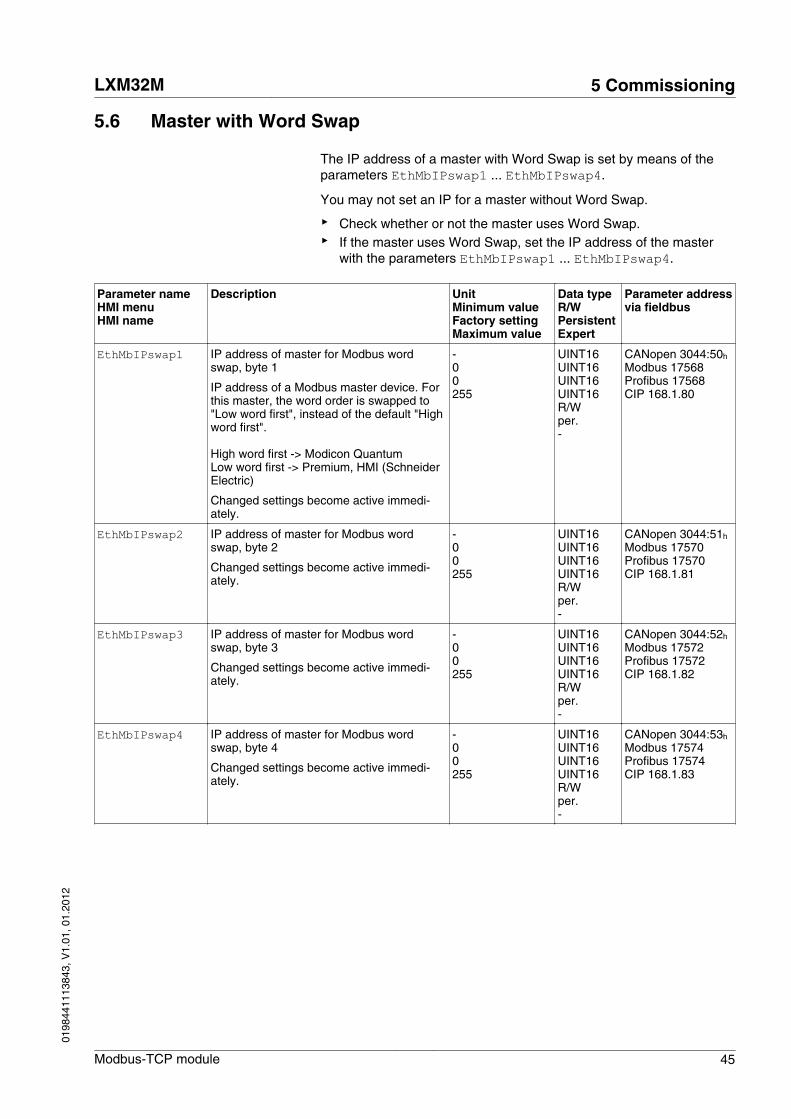
5.6 Master with Word Swap
The IP address of a master with Word Swap is set by means of theparameters EthMbIPswap1 ... EthMbIPswap4.
You may not set an IP for a master without Word Swap.
▶ Check whether or not the master uses Word Swap.▶ If the master uses Word Swap, set the IP address of the master
with the parameters EthMbIPswap1 ... EthMbIPswap4.
Parameter nameHMI menuHMI name
Description UnitMinimum valueFactory settingMaximum value
Data typeR/WPersistentExpert
Parameter addressvia fieldbus
EthMbIPswap1 IP address of master for Modbus wordswap, byte 1
IP address of a Modbus master device. Forthis master, the word order is swapped to"Low word first", instead of the default "Highword first".
High word first -> Modicon QuantumLow word first -> Premium, HMI (SchneiderElectric)
Changed settings become active immedi-ately.
-00255
UINT16UINT16UINT16UINT16 R/Wper.-
CANopen 3044:50h Modbus 17568Profibus 17568CIP 168.1.80
EthMbIPswap2 IP address of master for Modbus wordswap, byte 2
Changed settings become active immedi-ately.
-00255
UINT16UINT16UINT16UINT16 R/Wper.-
CANopen 3044:51h Modbus 17570Profibus 17570CIP 168.1.81
EthMbIPswap3 IP address of master for Modbus wordswap, byte 3
Changed settings become active immedi-ately.
-00255
UINT16UINT16UINT16UINT16 R/Wper.-
CANopen 3044:52h Modbus 17572Profibus 17572CIP 168.1.82
EthMbIPswap4 IP address of master for Modbus wordswap, byte 4
Changed settings become active immedi-ately.
-00255
UINT16UINT16UINT16UINT16 R/Wper.-
CANopen 3044:53h Modbus 17574Profibus 17574CIP 168.1.83
LXM32M 5 Commissioning
Modbus-TCP module 45
0198
4411
1384
3, V
1.01
, 01.
2012
5.7 Setting I/O-Scanning
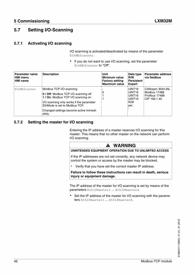
5.7.1 Activating I/O scanning
I/O scanning is activated/deactivated by means of the parameterEthMbScanner.
▶ If you do not want to use I/O scanning, set the parameterEthMbScanner to "Off".
Parameter nameHMI menuHMI name
Description UnitMinimum valueFactory settingMaximum value
Data typeR/WPersistentExpert
Parameter addressvia fieldbus
EthMbScanner Modbus TCP I/O scanning
0 / Off: Modbus TCP I/O scanning off1 / On: Modbus TCP I/O scanning on
I/O scanning only works if the parameterEthMode is set to Modbus TCP.
Changed settings become active immedi-ately.
-011
UINT16UINT16UINT16UINT16 R/Wper.-
CANopen 3044:28h Modbus 17488Profibus 17488CIP 168.1.40
5.7.2 Setting the master for I/O scanning
Entering the IP address of a master reserves I/O scanning for thismaster. This means that no other master on the network can performI/O scanning.
WARNINGUNINTENDED EQUIPMENT OPERATION DUE TO UNLIMITED ACCESS
If the IP addresses are not set correctly, any network device maycontrol the system or access by the master may be blocked.
• Verify that you have set the correct master IP address.
Failure to follow these instructions can result in death, seriousinjury or equipment damage.
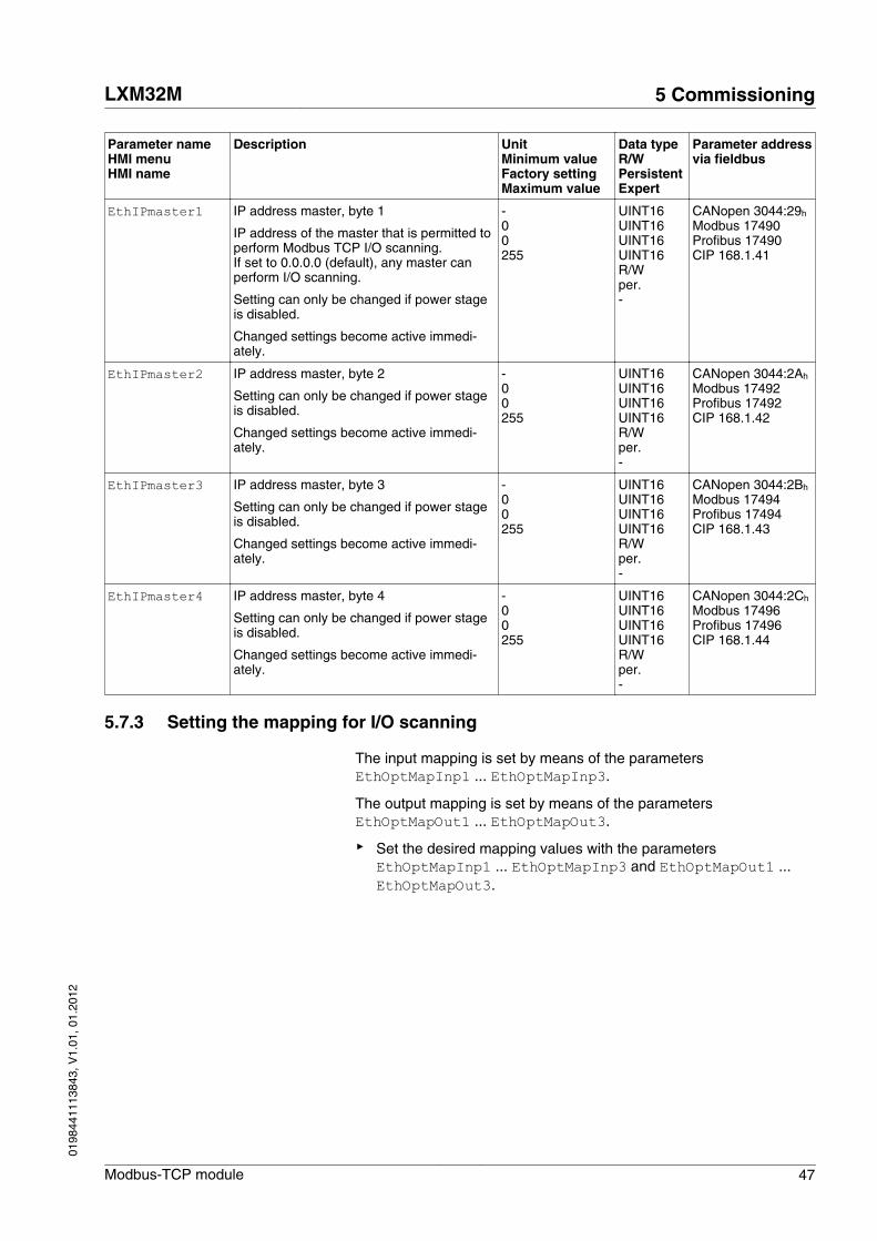
The IP address of the master for I/O scanning is set by means of theparameters EthIPmaster1 ... EthIPmaster4.
▶ Set the IP address of the master for I/O scanning with the parame-ters EthIPmaster1 ... EthIPmaster4.
5 Commissioning LXM32M
46 Modbus-TCP module
0198
4411
1384
3, V
1.01
, 01.
2012
Parameter nameHMI menuHMI name
Description UnitMinimum valueFactory settingMaximum value
Data typeR/WPersistentExpert
Parameter addressvia fieldbus
EthIPmaster1 IP address master, byte 1
IP address of the master that is permitted toperform Modbus TCP I/O scanning.If set to 0.0.0.0 (default), any master canperform I/O scanning.
Setting can only be changed if power stageis disabled.
Changed settings become active immedi-ately.
-00255
UINT16UINT16UINT16UINT16 R/Wper.-
CANopen 3044:29h Modbus 17490Profibus 17490CIP 168.1.41
EthIPmaster2 IP address master, byte 2
Setting can only be changed if power stageis disabled.
Changed settings become active immedi-ately.
-00255
UINT16UINT16UINT16UINT16 R/Wper.-
CANopen 3044:2Ah Modbus 17492Profibus 17492CIP 168.1.42
EthIPmaster3 IP address master, byte 3
Setting can only be changed if power stageis disabled.
Changed settings become active immedi-ately.
-00255
UINT16UINT16UINT16UINT16 R/Wper.-
CANopen 3044:2Bh Modbus 17494Profibus 17494CIP 168.1.43
EthIPmaster4 IP address master, byte 4
Setting can only be changed if power stageis disabled.
Changed settings become active immedi-ately.
-00255
UINT16UINT16UINT16UINT16 R/Wper.-
CANopen 3044:2Ch Modbus 17496Profibus 17496CIP 168.1.44
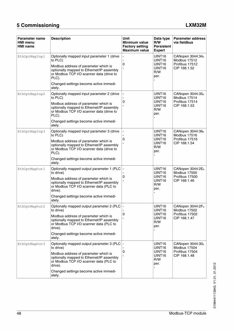
5.7.3 Setting the mapping for I/O scanning
The input mapping is set by means of the parametersEthOptMapInp1 ... EthOptMapInp3.
The output mapping is set by means of the parametersEthOptMapOut1 ... EthOptMapOut3.
▶ Set the desired mapping values with the parametersEthOptMapInp1 ... EthOptMapInp3 and EthOptMapOut1 ...EthOptMapOut3.
LXM32M 5 Commissioning
Modbus-TCP module 47
0198
4411
1384
3, V
1.01
, 01.
2012
Parameter nameHMI menuHMI name
Description UnitMinimum valueFactory settingMaximum value
Data typeR/WPersistentExpert
Parameter addressvia fieldbus
EthOptMapInp1 Optionally mapped input parameter 1 (driveto PLC)
Modbus address of parameter which isoptionally mapped to Ethernet/IP assemblyor Modbus TCP I/O scanner data (drive toPLC).
Changed settings become active immedi-ately.
--0-
UINT16UINT16UINT16UINT16 R/Wper.-
CANopen 3044:34h Modbus 17512Profibus 17512CIP 168.1.52
EthOptMapInp2 Optionally mapped input parameter 2 (driveto PLC)
Modbus address of parameter which isoptionally mapped to Ethernet/IP assemblyor Modbus TCP I/O scanner data (drive toPLC).
Changed settings become active immedi-ately.
--0-
UINT16UINT16UINT16UINT16 R/Wper.-
CANopen 3044:35h Modbus 17514Profibus 17514CIP 168.1.53
EthOptMapInp3 Optionally mapped input parameter 3 (driveto PLC)
Modbus address of parameter which isoptionally mapped to Ethernet/IP assemblyor Modbus TCP I/O scanner data (drive toPLC).
Changed settings become active immedi-ately.
--0-
UINT16UINT16UINT16UINT16 R/Wper.-
CANopen 3044:36h Modbus 17516Profibus 17516CIP 168.1.54
EthOptMapOut1 Optionally mapped output parameter 1 (PLCto drive)
Modbus address of parameter which isoptionally mapped to Ethernet/IP assemblyor Modbus TCP I/O scanner data (PLC todrive).
Changed settings become active immedi-ately.
--0-
UINT16UINT16UINT16UINT16 R/Wper.-
CANopen 3044:2Eh Modbus 17500Profibus 17500CIP 168.1.46
EthOptMapOut2 Optionally mapped output parameter 2 (PLCto drive)
Modbus address of parameter which isoptionally mapped to Ethernet/IP assemblyor Modbus TCP I/O scanner data (PLC todrive).
Changed settings become active immedi-ately.
--0-
UINT16UINT16UINT16UINT16 R/Wper.-
CANopen 3044:2Fh Modbus 17502Profibus 17502CIP 168.1.47
EthOptMapOut3 Optionally mapped output parameter 3 (PLCto drive)
Modbus address of parameter which isoptionally mapped to Ethernet/IP assemblyor Modbus TCP I/O scanner data (PLC todrive).
Changed settings become active immedi-ately.
--0-
UINT16UINT16UINT16UINT16 R/Wper.-
CANopen 3044:30h Modbus 17504Profibus 17504CIP 168.1.48
5 Commissioning LXM32M
48 Modbus-TCP module
0198
4411
1384
3, V
1.01
, 01.
2012
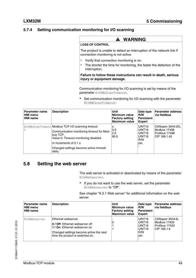
5.7.4 Setting communication monitoring for I/O scanning
WARNINGLOSS OF CONTROL
The product is unable to detect an interruption of the network link ifconnection monitoring is not active.
• Verify that connection monitoring is on.• The shorter the time for monitoring, the faster the detection of the
interruption.
Failure to follow these instructions can result in death, seriousinjury or equipment damage.
Communication monitoring for I/O scanning is set by means of theparameter EthMbScanTimeout.
▶ Set communication monitoring for I/O scanning with the parameterEthMbScanTimeout.
Parameter nameHMI menuHMI name
Description UnitMinimum valueFactory settingMaximum value
Data typeR/WPersistentExpert
Parameter addressvia fieldbus
EthMbScanTimeout
Modbus TCP I/O scanning timeout
Communication monitoring timeout for Mod-bus TCP.Value 0: Timeout monitoring disabled
In increments of 0.1 s.
Changed settings become active immedi-ately.
s0.02.060.0
UINT16UINT16UINT16UINT16 R/Wper.-
CANopen 3044:2Dh Modbus 17498Profibus 17498CIP 168.1.45
5.8 Setting the web server
The web server is activated or deactivated by means of the parameterEthWebserver.
▶ If you do not want to use the web server, set the parameterEthWebserver to "Off".
See chapter "6.3.1 Web server" for additional information on the webserver.
Parameter nameHMI menuHMI name
Description UnitMinimum valueFactory settingMaximum value
Data typeR/WPersistentExpert
Parameter addressvia fieldbus
EthWebserver Ethernet webserver
0 / Off: Ethernet webserver off1 / On: Ethernet webserver on
Changed settings become active the nexttime the product is switched on.
-011
UINT16UINT16UINT16UINT16 R/Wper.-
CANopen 3044:6h Modbus 17420Profibus 17420CIP 168.1.6
LXM32M 5 Commissioning
Modbus-TCP module 49
0198
4411
1384
3, V
1.01
, 01.
2012

5 Commissioning LXM32M
50 Modbus-TCP module
0198
4411
1384
3, V
1.01
, 01.
2012
6 Operation
6
WARNINGUNINTENDED OPERATION
• Do not write values to reserved parameters.• Do not write values to parameters unless you fully understand the
function.• Run initial tests without coupled loads.• Verify the use of the word sequence with fieldbus communication.• Do not establish a fieldbus connection unless you have fully
understood the communication principles.• Only start the system if there are no persons or obstructions in
the hazardous area.
Failure to follow these instructions can result in death, seriousinjury or equipment damage.
The chapter "Operation" describes the basic operating states, operat-ing modes and functions of the product.
LXM32M 6 Operation
Modbus-TCP module 51
0198
4411
1384
3, V
1.01
, 01.
2012
6.1 Operating states
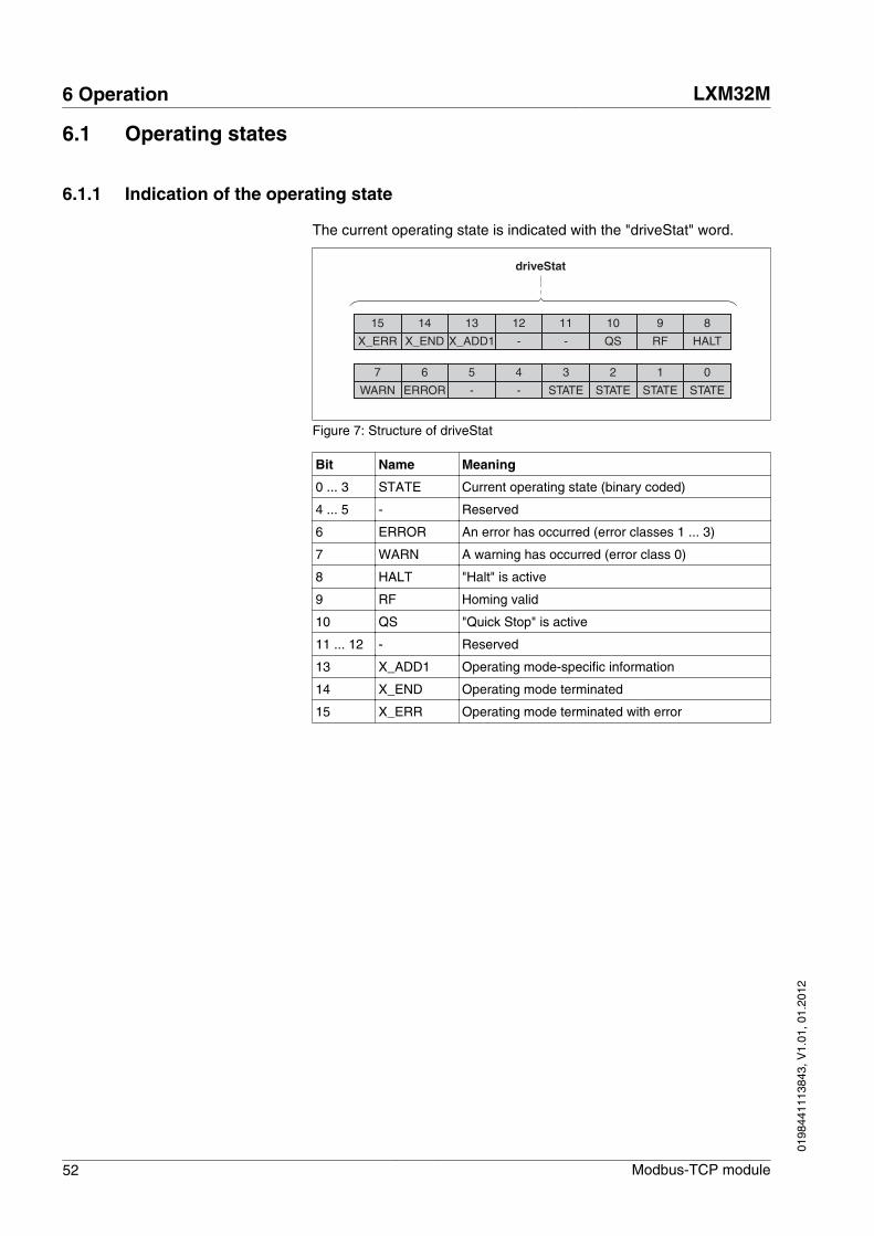
6.1.1 Indication of the operating state
The current operating state is indicated with the "driveStat" word.
15
X_ERR
14
X_END
13
X_ADD1
12
-
11
-
10
QS
9
RF
8
HALT
7
WARN
6
ERROR
5
-
4
-
3
STATE
2
STATE
1
STATE
0
STATE
driveStat
Figure 7: Structure of driveStat
Bit Name Meaning
0 ... 3 STATE Current operating state (binary coded)
4 ... 5 - Reserved
6 ERROR An error has occurred (error classes 1 ... 3)
7 WARN A warning has occurred (error class 0)
8 HALT "Halt" is active
9 RF Homing valid
10 QS "Quick Stop" is active
11 ... 12 - Reserved
13 X_ADD1 Operating mode-specific information
14 X_END Operating mode terminated
15 X_ERR Operating mode terminated with error
6 Operation LXM32M
52 Modbus-TCP module
0198
4411
1384
3, V
1.01
, 01.
2012

6.1.2 Changing the operating state
Bits 8 ... 15 of the word "dmControl" are used to set the operatingstate.
15
CU
14
CH
13
SH
12
-
11
FR
10
QS
9
EN
8
DS
7
MT
6
ACTION
5
ACTION
4
MODE
3
MODE
2
MODE
1
MODE
0
MODE
dmControl
Figure 8: Structure dmControl bits 8 ... 15
Bit Name Meaning Operating state
8 DS Disable power stage 6 Operation Enabled -> 4 Ready To Switch On
9 EN Enable power stage 4 Ready To Switch On -> 6 Operation Enabled
10 QS Executing a "Quick Stop" 6 Operation Enabled -> 7 Quick Stop Active
11 FR Execute "Fault Reset" 7 Quick Stop Active -> 6 Operation Enabled9 Fault -> 4 Ready To Switch On
12 - Reserved Reserved
13 SH Execute "Halt" 6 Operation Enabled
14 CH Clear "Halt" 6 Operation Enabled
15 CU Resume operating mode interrupted by"Halt"
6 Operation Enabled
In the case of an access, the bits respond to a 0->1 change to triggerthe corresponding function.
If a request for changing the operating state is not successful, thisrequest is ignored. There is no error response.
Ambivalent bit combinations are treated in accordance with the follow-ing priority list (highest priority bit 8, lowest priority bit 14 and bit 15):
• Bit 8 (disable power stage) prior to bit 9 (enable power stage)• Bit 10 ("Quick Stop") prior to bit 11 ("Fault Reset")• Bit 13 (execute "Halt") prior to bit 14 (clear "Halt") and bit 15
(resume operating mode interrupted by "Halt")
LXM32M 6 Operation
Modbus-TCP module 53
0198
4411
1384
3, V
1.01
, 01.
2012

6.2 Operating modes
6.2.1 Indicating and monitoring the operating mode
The word "mfStat" is used to indicate the current operating mode.
15
-
14
-
13
-
12
-
11
CAP2 1
10
CAP2 0
9
CAP1 1
8
CAP1 0
7
MT
6
ME
5
DE
4
MODE
3
MODE
2
MODE
1
MODE
0
MODE
mfStat
Figure 9: Structure mfStat
Bit Name Description
0 ... 4 MODE Indicates the current operating mode
Value 01h: Profile PositionValue 03h: Profile VelocityValue 04h: Profile TorqueValue 06h: HomingValue 1Fh: JogValue 1Eh: Electronic GearValue 1Dh: Motion Sequence
5 DE The "DE" bit relates to parameters that are independentof "Mode Toggle" (MT). The "DE" bit is set if a datavalue in the process data channel is invalid.
6 ME The "ME" bit relates to parameters that are dependenton "Mode Toggle" (MT). The "ME" bit is set if a requestfrom a master (starting an operating mode) was rejec-ted.
7 MT Handshake via "Mode Toggle"
8 ... 9 CAP1 Bit 0 and bit 1 of parameter _Cap1Count10 ... 11 CAP2 Bit 0 and bit 1 of parameter _Cap2Count12 ... 15 - Reserved
6 Operation LXM32M
54 Modbus-TCP module
0198
4411
1384
3, V
1.01
, 01.
2012

6.2.2 Starting and changing an operating mode
Bits 0 ... 7 in the word "dmControl" are used to set the operatingmode.
15
CU
14
CH
13
SH
12
-
11
FR
10
QS
9
EN
8
DS
7
MT
6
ACTION
5
ACTION
4
MODE
3
MODE
2
MODE
1
MODE
0
MODE
dmControl
Figure 10: Structure dmControl bits 0 ... 7
Bit Name Description
0 ... 4 MODE Operating mode
Value 01h: Profile PositionValue 03h: Profile VelocityValue 04h: Profile TorqueValue 06h: HomingValue 1Fh: JogValue 1Eh: Electronic GearValue 1Dh: Motion Sequence
5 ... 6 ACTION Operating mode-dependent
7 MT Handshake via Mode Toggle
The operating modes can be changed during operation. For this pur-pose, the current process must be completed or explicitly canceled.The motor must be at a standstill.
The master must enter the following values to activate an operatingmode or to change reference values:
• Reference values, depending on desired operating mode• Operating mode in "dmControl", bits 0 ... 4 (MODE).• Action for this operating mode in bit 5 and bit 6 (ACTION)• Toggle bit 7 (MT)
The following chapters describe the possible operating modes, func-tions and the corresponding reference values.
LXM32M 6 Operation
Modbus-TCP module 55
0198
4411
1384
3, V
1.01
, 01.
2012

6.2.3 Overview of operating modes
The table below provides an overview of the operating modes.Detailed information can be found on the following pages.
Operating mode Method dmControlBits 0 ... 6MODE+ACTION
Reference value RefA32 Reference value RefB32
Jog 1Fh Value 0: No movement
Value 1: Slow movementin positive direction
Value 2: Slow movementin negative direction
Value 5: Fast movement inpositive direction
Value 6: Fast movement innegative direction
-
Electronic Gear Position synchroni-zation without com-pensation move-ment
1Eh As GEARdenom As GEARnum
Position synchroni-zation with compen-sation movement
3Eh As GEARdenom As GEARnum
Velocity synchroni-zation
5Eh As GEARdenom As GEARnum
Profile Torque 24h As PTtq_target As RAMP_tq_slopeProfile Velocity 23h As PVv_target -
Profile Position Absolute 01h As PPv_target As PPp_targetRelative with refer-ence to the cur-rently set targetposition
21h As PPv_target As PPp_target
Relative with refer-ence to the currentmotor position
41h As PPv_target As PPp_target
Homing Position setting 06h - As HMp_setPReference move-ment
26h As HMmethod -
Motion Sequence Start sequence 1Dh Data set number Value 1: Use data setnumber
Start individual dataset
3Dh Data set number -
6 Operation LXM32M
56 Modbus-TCP module
0198
4411
1384
3, V
1.01
, 01.
2012
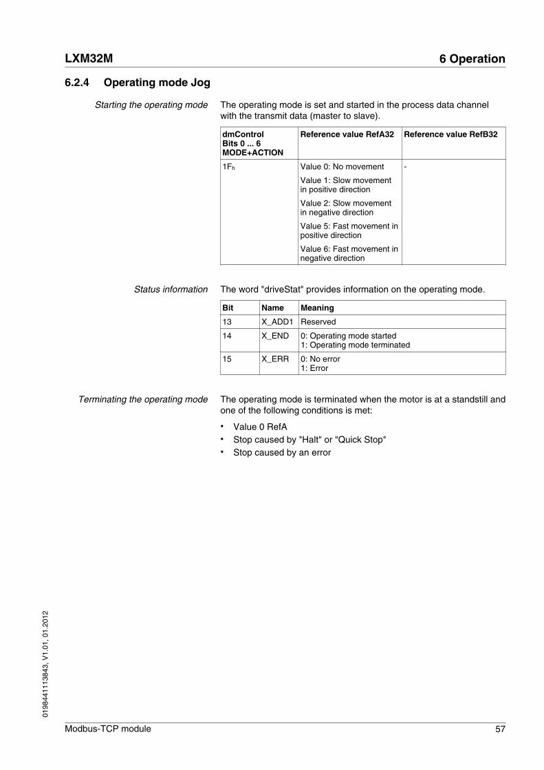
6.2.4 Operating mode Jog
Starting the operating mode The operating mode is set and started in the process data channelwith the transmit data (master to slave).
dmControlBits 0 ... 6MODE+ACTION
Reference value RefA32 Reference value RefB32
1Fh Value 0: No movement
Value 1: Slow movementin positive direction
Value 2: Slow movementin negative direction
Value 5: Fast movement inpositive direction
Value 6: Fast movement innegative direction
-
Status information The word "driveStat" provides information on the operating mode.
Bit Name Meaning
13 X_ADD1 Reserved
14 X_END 0: Operating mode started1: Operating mode terminated
15 X_ERR 0: No error1: Error
Terminating the operating mode The operating mode is terminated when the motor is at a standstill andone of the following conditions is met:
• Value 0 RefA• Stop caused by "Halt" or "Quick Stop"• Stop caused by an error
LXM32M 6 Operation
Modbus-TCP module 57
0198
4411
1384
3, V
1.01
, 01.
2012

6.2.5 Operating mode Electronic Gear
Starting the operating mode The operating mode is set and started in the process data channelwith the transmit data (master to slave).
Method dmControlBits 0 ... 6MODE+ACTION
Reference value RefA32 Reference value RefB32
Position synchronization without compen-sation movement
1Eh As GEARdenom As GEARnum
Position synchronization with compensa-tion movement
3Eh As GEARdenom As GEARnum
Velocity synchronization 5Eh As GEARdenom As GEARnum
Status information The word "driveStat" provides information on the operating mode.
Bit Name Meaning
13 X_ADD1 1: Reference velocity reached 1)
14 X_END 0: Operating mode started1: Operating mode terminated
15 X_ERR 0: No error1: Error
1) Only with method Velocity synchronization and with active velocity window.
Terminating the operating mode The operating mode is terminated when the motor is at a standstill andone of the following conditions is met:
• Stop caused by "Halt" or "Quick Stop"• Stop caused by an error
6 Operation LXM32M
58 Modbus-TCP module
0198
4411
1384
3, V
1.01
, 01.
2012

6.2.6 Operating mode Profile Torque
Starting the operating mode The operating mode is set and started in the process data channelwith the transmit data (master to slave).
dmControlBits 0 ... 6MODE+ACTION
Reference value RefA32 Reference value RefB32
24h As PTtq_target As RAMP_tq_slope
Status information The word "driveStat" provides information on the operating mode.
Bit Name Meaning
13 X_ADD1 0: Target torque not reached1: Target torque reached
14 X_END 0: Operating mode started1: Operating mode terminated
15 X_ERR 0: No error1: Error
Terminating the operating mode The operating mode is terminated when the motor is at a standstill andone of the following conditions is met:
• Stop caused by "Halt" or "Quick Stop"• Stop caused by an error
LXM32M 6 Operation
Modbus-TCP module 59
0198
4411
1384
3, V
1.01
, 01.
2012

6.2.7 Operating mode Profile Velocity
Starting the operating mode The operating mode is set and started in the process data channelwith the transmit data (master to slave).
dmControlBits 0 ... 6MODE+ACTION
Reference value RefA32 Reference value RefB32
23h As PVv_target -
Status information The word "driveStat" provides information on the operating mode.
Bit Name Meaning
13 X_ADD1 0: Target velocity not reached1: Target velocity reached
14 X_END 0: Operating mode started1: Operating mode terminated
15 X_ERR 0: No error1: Error
Terminating the operating mode The operating mode is terminated when the motor is at a standstill andone of the following conditions is met:
• Stop caused by "Halt" or "Quick Stop"• Stop caused by an error
6 Operation LXM32M
60 Modbus-TCP module
0198
4411
1384
3, V
1.01
, 01.
2012
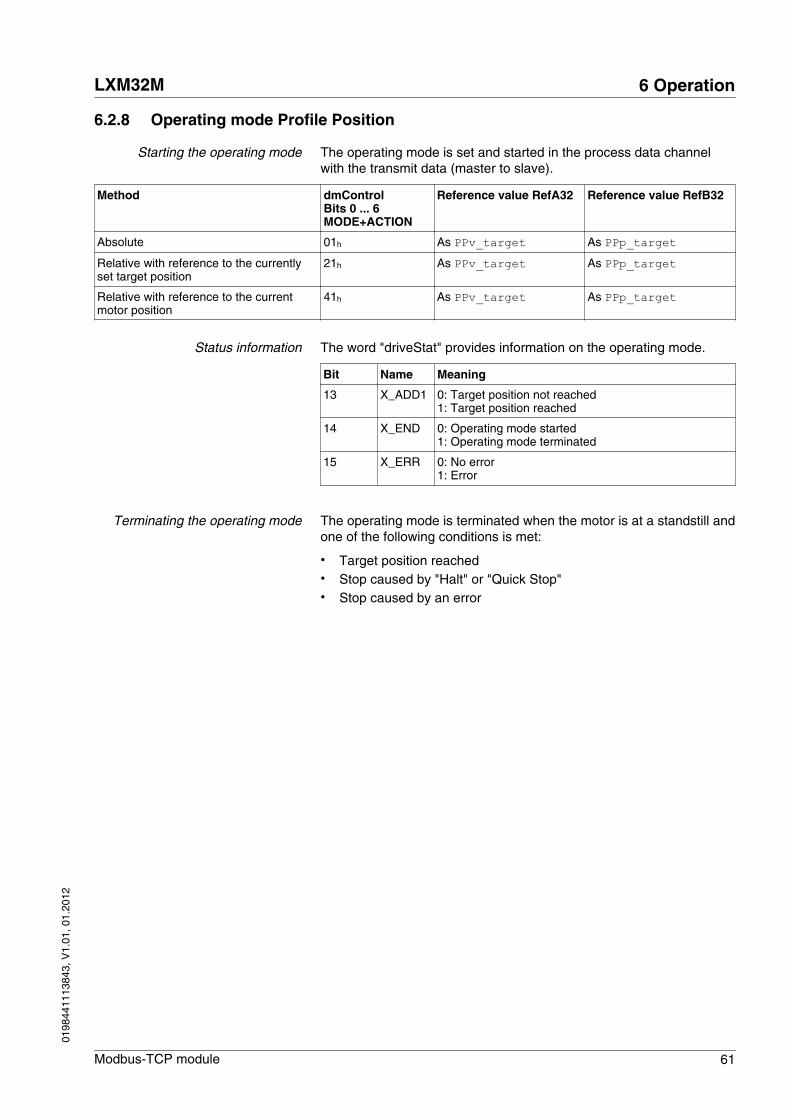
6.2.8 Operating mode Profile Position
Starting the operating mode The operating mode is set and started in the process data channelwith the transmit data (master to slave).
Method dmControlBits 0 ... 6MODE+ACTION
Reference value RefA32 Reference value RefB32
Absolute 01h As PPv_target As PPp_targetRelative with reference to the currentlyset target position
21h As PPv_target As PPp_target
Relative with reference to the currentmotor position
41h As PPv_target As PPp_target
Status information The word "driveStat" provides information on the operating mode.
Bit Name Meaning
13 X_ADD1 0: Target position not reached1: Target position reached
14 X_END 0: Operating mode started1: Operating mode terminated
15 X_ERR 0: No error1: Error
Terminating the operating mode The operating mode is terminated when the motor is at a standstill andone of the following conditions is met:
• Target position reached• Stop caused by "Halt" or "Quick Stop"• Stop caused by an error
LXM32M 6 Operation
Modbus-TCP module 61
0198
4411
1384
3, V
1.01
, 01.
2012

6.2.9 Operating mode Homing
Starting the operating mode The operating mode is set and started in the process data channelwith the transmit data (master to slave).
Method dmControlBits 0 ... 6MODE+ACTION
Reference value RefA32 Reference value RefB32
Position setting 06h - As HMp_setPReference movement 26h As HMmethod -
Status information The word "driveStat" provides information on the operating mode.
Bit Name Meaning
13 X_ADD1 Reserved
14 X_END 0: Operating mode started1: Operating mode terminated
15 X_ERR 0: No error1: Error
Terminating the operating mode The operating mode is terminated when the motor is at a standstill andone of the following conditions is met:
• Homing successful• Stop caused by "Halt" or "Quick Stop"• Stop caused by an error
6 Operation LXM32M
62 Modbus-TCP module
0198
4411
1384
3, V
1.01
, 01.
2012

6.2.10 Operating mode Motion Sequence
Starting the operating mode The operating mode is set and started in the process data channelwith the transmit data (master to slave).
Method dmControlBits 0 ... 6MODE+ACTION
Reference value RefA32 Reference value RefB32
Start sequence 1Dh Data set number Value 1: Use data setnumber
Start individual data set 3Dh Data set number -
Status information The word "driveStat" provides information on the operating mode.
Bit Name Meaning
13 X_ADD1 1: End of a sequence
14 X_END 0: Operating mode started1: Operating mode terminated
15 X_ERR 0: No error1: Error
Terminating the operating mode The operating mode is terminated when the motor is at a standstill andone of the following conditions is met:
• Individual data set terminated• Individual data set of a sequence terminated (waiting for transition
condition to be fulfilled)• Sequence terminated• Stop caused by "Halt" or "Quick Stop"• Stop caused by an error
LXM32M 6 Operation
Modbus-TCP module 63
0198
4411
1384
3, V
1.01
, 01.
2012

6.3 Extended settings
6.3.1 Web server
Functions The product features an integrated web server.
The web server offers the following features:
• Display status information• Display and change parameters• Display and change network settings• Display and change Modbus TCP settings• Display and change EtherNet/IP settings• Display and change settings for the FDR service• Display network statistics• User-specific adaptation of the website
See chapter "6.3.2 FTP server"
6.3.1.1 Setting the web server
The web server is activated or deactivated by means of the parameterEthWebserver.
▶ If you do not want to use the web server, set the parameterEthWebserver to "Off".
Parameter nameHMI menuHMI name
Description UnitMinimum valueFactory settingMaximum value
Data typeR/WPersistentExpert
Parameter addressvia fieldbus
EthWebserver Ethernet webserver
0 / Off: Ethernet webserver off1 / On: Ethernet webserver on
Changed settings become active the nexttime the product is switched on.
-011
UINT16UINT16UINT16UINT16 R/Wper.-
CANopen 3044:6h Modbus 17420Profibus 17420CIP 168.1.6
6.3.1.2 Accessing the web server
The web server of the product can be accessed via a Web browser.
■ The product must have a valid IP address.▶ Start an Internet browser.▶ Enter the IP address of the product in the address bar.▶ Enter "USER" as the username and the password (uppercase).
6 Operation LXM32M
64 Modbus-TCP module
0198
4411
1384
3, V
1.01
, 01.
2012

6.3.1.3 User interface
Structure of the web server user interface:
1
2
3
Figure 11: User interface of the web server
(1) Main menu(2) Submenu(3) Content
Main menu Submenu Content
Home English Homepage
Documentation - Link to websitewww.schneider-electric.com
Monitoring Drive monitor Status information
Drive parameter Display and change parame-ters
Network Setup Network parameters Network settings
Modbus scanner Modbus settings
Eth/IP scanner EtherNet/IP settings
Fast device replacement FDR service settings
Administration Change web server passwords
Diagnostics TCP/IP statistics Information on TCP/IP
Modbus statistics Information on Modbus
Ethernet IP statistics Information on EtherNet/IP
LXM32M 6 Operation
Modbus-TCP module 65
0198
4411
1384
3, V
1.01
, 01.
2012

6.3.2 FTP server
Functions The product features an integrated FTP server.
The FTP server lets you upload a CFG file and a JPG file to modifythe content and appearance of the web server.
The following items can be modified:
• Product Name• Link under "Documentation..."• Product image (picture on the start page)
6.3.2.1 Accessing the FTP server
The FTP server of the product can be accessed via an FTP client.
■ The product must have a valid IP address.▶ Start an FTP client.▶ Enter the IP address of the product when prompted for a "Host/
Server" .▶ Enter "USER" as the username and the password (uppercase).
6.3.2.2 User-specific adaptation of the website
You can upload a CFG file and a JPG file to modify the content andappearance of the web server.
CFG file File name of the CFG file: http.cfg
The CFG file has the following structure:
[ProductName]Lexium 32 by MyCompany
[ProductLink]http://www.my-company.com
[ProductImageName]mypic.jpg
JPG file The JPG file replaces the product image (picture on the start page).
The file name of the JPG file must match the file name specified in theCFG file.
NOTE: The entire file name is case-sensitive (even the extensionJPG).
Uploading files ▶ Connect via an FTP client.▶ Save the CFG file at the top level.▶ Create a folder "html".▶ Below the "html" folder, create an "images" folder.▶ Save the JPG file in the "images" folder.▶ Switch the product off and on.
6 Operation LXM32M
66 Modbus-TCP module
0198
4411
1384
3, V
1.01
, 01.
2012

6.3.3 FDR service (Fast Device Replacement)
The FDR service uses standard DHCP and TFTP (Trivial File TransferProtocol) technologies to simplify maintenance of Ethernet devices.
For example, the FDR service is used to replace a defective device bya new device. The service allows for detection, configuration and auto-matic start of the new device without complex manual user interaction.
The main steps:
• A defective device that uses the FDR service is removed.• The new device that is pre-configured with the "DeviceName" of
the defective device is installed in the network.• The FDR server which can be a Quantum- or Premium-SPS PLC
Ethernet module detects the new device, configures it with its IPaddress and transmits the configuration parameters.
• The replacement device checks the parameters for compatibility.
LXM32M 6 Operation
Modbus-TCP module 67
0198
4411
1384
3, V
1.01
, 01.
2012

6 Operation LXM32M
68 Modbus-TCP module
0198
4411
1384
3, V
1.01
, 01.
2012
7 Diagnostics and troubleshooting
7
7.1 Fieldbus communication error diagnostics
Connections for fieldbus mode If the product cannot be addressed via the fieldbus, first check theconnections. The product manual contains the technical data of thedevice and information on network and device installation. Check thefollowing:
• 24Vdc power supply• Power connections to the device• Fieldbus cable and fieldbus wiring
You can also use the commissioning software for troubleshooting.
Fieldbus function test If the connections are correct, check the settings for the fieldbusaddresses. After correct configuration of the transmission data, testfieldbus mode.
▶ In addition to the master, activate a bus monitor that, as a passivedevice, displays messages.
▶ Switch the supply voltage off and on.▶ Observe the network messages that are generated briefly after the
supply voltage is switched on. A bus monitor can be used to recordthe elapsed time between messages and the relevant informationin the messages.
Addressing, parameterization If it is impossible to connect to a device, check the following:
▶ Addressing
Each network device must have a unique IP address.
LXM32M 7 Diagnostics and troubleshooting
Modbus-TCP module 69
0198
4411
1384
3, V
1.01
, 01.
2012

7.2 Status LEDs
The status of the module is indicated by four LEDs.
A
B
3 4
1 2
Figure 12: Overview of the LEDs at the module
(1) Network activity interface A(2) Module status(3) Network activity interface B(4) Network status
NOTE: The meaning of the flash signals depends on the selected pro-tocol.
▶ Check whether the protocol is set to "EtherNet/IP" or "ModbusTCP".
Network activity LED 1 and LED 3 The table below shows the meaning of the flashing signals for networkactivity.
Color Status Meaning
- Off No connection
Green On Connection with 100 [MB/s]
Yellow On Connection with 10 [MB/s]
Green Flashing Activity with 100 [MB/s]
Yellow Flashing Activity with 10 [MB/s]
7 Diagnostics and troubleshooting LXM32M
70 Modbus-TCP module
0198
4411
1384
3, V
1.01
, 01.
2012

Module status LED 2 The table below shows the meaning of the flashing signals for themodule status.
Color LED Meaning for EtherNet/IP 1) Meaning for Modbus TCP 1)
- Off No power supply No IP address or no power supply
Green/yellow Flashing Start-up Start-up
Green On Ready for operation Ready for operation
Green Flashing Module is not configured or scanner isIdle
Not ready (no connection, ...)
Red Flashing Recoverable error Recoverable error
Red On Irrecoverable error Irrecoverable error
1) Depends on the selected protocol (parameter EthMode)
Network status LED 4 The table below shows the meaning of the flashing signals for the net-work status.
Color LED Meaning for EtherNet/IP 1) Meaning for Modbus TCP 1)
- Off No IP address or no power supply No IP address or no power supply
Green/yellow Flashing Start-up Start-up
Green On Connected At least 1 port is connected and the IPaddress has been set
Green Flashing 3 times - No connection, IP address has been set
Green Flashing 4 times - IP address conflict
Green Flashing 5 times - BOOTP or DHCP active
Green Flashing No connection -
Red Flashing Timeout -
Red On IP address conflict -
1) Depends on the selected protocol (parameter EthMode)
LXM32M 7 Diagnostics and troubleshooting
Modbus-TCP module 71
0198
4411
1384
3, V
1.01
, 01.
2012

7.3 Error indication
The last cause of error and the last 10 error messages are stored. Youcan display the last 10 error messages using the commissioning soft-ware and the fieldbus.
Asynchronous errors Asynchronous errors are triggered by internal monitoring (for example,temperature) or by external monitoring (for example, limit switch). Anerror response is initiated if an asynchronous error occurs.
Asynchronous errors are indicated in the following way:
• Transition to operating state 7 Quick Stop Active or to operatingstate 9 Fault.
• Information in the words "driveStat", "mfStat", "motionStat" and"driveInput" during I/O scanning, see chapter"3.3.4.2 I/O scanning Input"
• Error number is written to parameter _LastError
The parameters _LastError or _LastWarning can be used in theinput mapping for I/O scanning. This way, error numbers are easy toread out.
Modbus response
Depending on the type of processing, two types of Modbus responsesare possible:
• Positive Modbus response
- The "Function Code" in the Modbus response corresponds tothe "Function Code" in the Modbus request.
• Negative Modbus response
- The client receives pertinent information on error detection dur-ing processing;
- The "Function Code" in Modbus response corresponds to the"Function Code" in the Modbus request + 80h.
- The "Exception Code" indicates the cause of the error.
If a syntactically incorrect Modbus PDU (Protocol Data Unit) is trans-mitted, the connection is terminated. In the case of other other error, anegative Modbus response is sent.
7 Diagnostics and troubleshooting LXM32M
72 Modbus-TCP module
0198
4411
1384
3, V
1.01
, 01.
2012

Excep-tion Code
Name Description
01 Illegal Function Code The "Function Code" is unknown to theserver.
02 Illegal Data Address Depends on the Modbus request
03 Illegal Data Value Depends on the Modbus request
04 Server Failure The server was unable to properly termi-nate processing.
05 Acknowledge The server has accepted the Modbusrequest. However, the execution takes arelatively long time. The server thereforeonly returns an acknowledgement con-firming receipt of the service request.
06 Server Busy The server was unable to accept theModbus request. It is the responsibility ofthe application on the client to determinewhether and when to re-send the request.
0A Gateway Problem The gateway path is unavailable.
0B Gateway Problem The targeted device does not respond.The gateway generates this error.
LXM32M 7 Diagnostics and troubleshooting
Modbus-TCP module 73
0198
4411
1384
3, V
1.01
, 01.
2012

7 Diagnostics and troubleshooting LXM32M
74 Modbus-TCP module
0198
4411
1384
3, V
1.01
, 01.
2012

8 Accessories and spare parts
8
8.1 Cables
Description Order no.
2 m, 2 x RJ45, shielded twisted pair cable 490NTW00002
5 m, 2 x RJ45, shielded twisted pair cable 490NTW00005
12 m, 2 x RJ45, shielded twisted pair cable 490NTW00012
2 m, 2 x RJ45, shielded twisted pair cable with UL and CSA 22.1 certification 490NTW00002U
5 m, 2 x RJ45, shielded twisted pair cable with UL and CSA 22.1 certification 490NTW00005U
12 m, 2 x RJ45, shielded twisted pair cable with UL and CSA 22.1 certification 490NTW00012U
LXM32M 8 Accessories and spare parts
Modbus-TCP module 75
0198
4411
1384
3, V
1.01
, 01.
2012

8 Accessories and spare parts LXM32M
76 Modbus-TCP module
0198
4411
1384
3, V
1.01
, 01.
2012

9 Glossary
9
9.1 Units and conversion tables
The value in the specified unit (left column) is calculated for thedesired unit (top row) with the formula (in the field).
Example: conversion of 5 meters [m] to yards [yd]5 m / 0.9144 = 5.468 yd
9.1.1 Length
in ft yd m cm mm
in - / 12 / 36 * 0.0254 * 2.54 * 25.4
ft * 12 - / 3 * 0.30479 * 30.479 * 304.79
yd * 36 * 3 - * 0.9144 * 91.44 * 914.4
m / 0.0254 / 0.30479 / 0.9144 - * 100 * 1000
cm / 2.54 / 30.479 / 91.44 / 100 - * 10
mm / 25.4 / 304.79 / 914.4 / 1000 / 10 -
9.1.2 Mass
lb oz slug kg g
lb - * 16 * 0.03108095 * 0.4535924 * 453.5924
oz / 16 - * 1.942559*10-3 * 0.02834952 * 28.34952
slug / 0.03108095 / 1.942559*10-3 - * 14.5939 * 14593.9
kg / 0.45359237 / 0.02834952 / 14.5939 - * 1000
g / 453.59237 / 28.34952 / 14593.9 / 1000 -
9.1.3 Force
lb oz p dyne N
lb - * 16 * 453.55358 * 444822.2 * 4.448222
oz / 16 - * 28.349524 * 27801 * 0.27801
p / 453.55358 / 28.349524 - * 980.7 * 9.807*10-3
dyne / 444822.2 / 27801 / 980.7 - / 100*103
N / 4.448222 / 0.27801 / 9.807*10-3 * 100*103 -
9.1.4 Power
HP W
HP - * 746
W / 746 -
LXM32M 9 Glossary
Modbus-TCP module 77
0198
4411
1384
3, V
1.01
, 01.
2012

9.1.5 Rotation
min-1 (RPM) rad/s deg./s
min-1 (RPM) - * π / 30 * 6
rad/s * 30 / π - * 57.295
deg./s / 6 / 57.295 -
9.1.6 Torque
lb‧in lb‧ft oz‧in Nm kp‧m kp‧cm dyne‧cm
lb‧in - / 12 * 16 * 0.112985 * 0.011521 * 1.1521 * 1.129*106
lb‧ft * 12 - * 192 * 1.355822 * 0.138255 * 13.8255 * 13.558*106
oz‧in / 16 / 192 - * 7.0616*10-3 * 720.07*10-6 * 72.007*10-3 * 70615.5
Nm / 0.112985 / 1.355822 / 7.0616*10-3 - * 0.101972 * 10.1972 * 10*106
kp‧m / 0.011521 / 0.138255 / 720.07*10-6 / 0.101972 - * 100 * 98.066*106
kp‧cm / 1.1521 / 13.8255 / 72.007*10-3 / 10.1972 / 100 - * 0.9806*106
dyne‧cm / 1.129*106 / 13.558*106 / 70615.5 / 10*106 / 98.066*106 / 0.9806*106 -
9.1.7 Moment of inertia
lb‧in2 lb‧ft2 kg‧m2 kg‧cm2 kp‧cm‧s2 oz‧in2
lb‧in2 - / 144 / 3417.16 / 0.341716 / 335.109 * 16
lb‧ft2 * 144 - * 0.04214 * 421.4 * 0.429711 * 2304
kg‧m2 * 3417.16 / 0.04214 - * 10*103 * 10.1972 * 54674
kg‧cm2 * 0.341716 / 421.4 / 10*103 - / 980.665 * 5.46
kp‧cm‧s2 * 335.109 / 0.429711 / 10.1972 * 980.665 - * 5361.74
oz‧in2 / 16 / 2304 / 54674 / 5.46 / 5361.74 -
9.1.8 Temperature
°F °C K
°F - (°F - 32) * 5/9 (°F - 32) * 5/9 + 273.15
°C °C * 9/5 + 32 - °C + 273.15
K (K - 273.15) * 9/5 + 32 K - 273.15 -
9.1.9 Conductor cross section
AWG 1 2 3 4 5 6 7 8 9 10 11 12 13
mm2 42.4 33.6 26.7 21.2 16.8 13.3 10.5 8.4 6.6 5.3 4.2 3.3 2.6
AWG 14 15 16 17 18 19 20 21 22 23 24 25 26
mm2 2.1 1.7 1.3 1.0 0.82 0.65 0.52 0.41 0.33 0.26 0.20 0.16 0.13
9 Glossary LXM32M
78 Modbus-TCP module
0198
4411
1384
3, V
1.01
, 01.
2012

9.2 Terms and Abbreviations
See chapter "2.5 Standards and terminology" for information on thepertinent standards on which many terms are based. Some terms andabbreviations may have specific meanings with regard to the stand-ards.
CIP Common Industrial Protocol, general specification for communicationbetween fieldbus devices.
Client First transmitter, then recipient of fieldbus messages in the client-server relationship. Starts transmission with a transmission to theserver; the reference point is the server object dictionary.
DOM Date of manufacturing: The nameplate of the product shows the dateof manufacture in the format DD.MM.YY or in the formatDD.MM.YYYY. Example:31.12.09 corresponds to December 31, 2009 31.12.2009 corresponds to December 31, 2009
Error Discrepancy between a detected (computed, measured or signaled)value or condition and the specified or theoretically correct value orcondition.
Error class Classification of errors into groups. The different error classes allowfor specific responses to errors, for example by severity.
Factory setting Factory settings when the product is shipped
Fatal error In the case of fatal error, the product is no longer able to control themotor so that the power stage must be immediately disabled.
Fault Fault is a state that can be caused by an error. Further informationcan be found in the pertinent standards such as IEC 61800-7, ODVACommon Industrial Protocol (CIP).
Fault reset A function used to restore the drive to an operational state after adetected error is cleared by removing the cause of the error so thatthe error is no longer active.
Input Output and input refer to the direction of data transmission from theperspective of the master. Input: Status messages from the slave tothe master, see also Output.
Master Active bus device that controls the data traffic on the network.
Output Output and input refer to the direction of data transmission from theperspective of the master. Output: Commands from the master to theslave, see also Input.
Parameter Device data and values that can be read and set (to a certain extent)by the user.
Persistent Indicates whether the value of the parameter remains in the memoryafter the device is switched off.
Quick Stop The Quick Stop function can be used for fast deceleration of a move-ment in the case of an error or via a command.
User-defined unit Unit whose reference to motor movement can be determined by theuser via parameters.
Warning If the term is used outside the context of safety instructions, a warningalerts to a potential problem that was detected by a monitoring func-tion. A warning does not cause a transition of the operating state.
LXM32M 9 Glossary
Modbus-TCP module 79
0198
4411
1384
3, V
1.01
, 01.
2012

9 Glossary LXM32M
80 Modbus-TCP module
0198
4411
1384
3, V
1.01
, 01.
2012

10 Index
10
A
Abbreviations 79
Accessories and spare parts 75
B
Before you begin
Safety information 11
C
Cables 75
CAD data 7
Commissioning 37
First setup 38
Commissioning the device 37
D
Diagnostics 69
E
Electrical installation 36
Electronic Gear 58
Error diagnostics
Connections to for fieldbus operation 69
Error indication 72
Errors
Troubleshooting 69
Examples 33
F
First setup
Commissioning 38
Further reading 8
G
Glossary 77
H
Hazard categories 12
Homing 62
I
Input 22
Installation 35
electrical 36
Intended use 11
Introduction 9
J
Jog 57
M
Manuals
Source 7
Motion Sequence 63
LXM32M 10 Index
Modbus-TCP module 81
0198
4411
1384
3, V
1.01
, 01.
2012

O
Operating mode
Electronic Gear 58
Homing 62
Jog 57
Motion Sequence 63
Profile Position 61
Profile Torque 59
Profile Velocity 60
Operating modes 54
Operating modes, starting and chang-ing 55
Operating modes, starting and changing 55
Operating state, changing the 53
Operating states 52
Indicating operating states 52, 54
Operating state, changing the 53
Operating states, indication 52, 54
Operation 51
Output 22
P
Parameter channel 26
Profile Position 61
Profile Torque 59
Profile Velocity 60
Q
Qualification of personnel 11
S
Source
CAD data 7
Manuals 7
Switching on the device 38
T
Terms 79
U
Units and conversion tables 77
10 Index LXM32M
82 Modbus-TCP module
0198
4411
1384
3, V
1.01
, 01.
2012