Embed Size (px)
Citation preview
Revision M October 2008 Copyright © 2003-2008 AMETEK Programmable Power Divison. All rights reserved. P/N 7004-981
Lx \ Ls Series II AC Power Source
Programming Manual
TEL: +1 (858) 677-9040 FAX: +1 (858) 677-0940
Email: [email protected] Web Site: www.california-instruments.com
AMETEK Programmable Power Division. 1
Programming Manual - Rev M Lx \ Ls Series II
Refers to:
Lx Series AC Power Source/Analyzers - Series II
Ls Series AC Power Sources - Series II Models:
Single chassis: 3000Lx, 4500Lx, 6000Lx Multiple chassis: 9000Lx/2, 12000Lx/2, 13500Lx/3, 18000Lx/3
Single chassis: 3000Ls, 4500Ls, 6000Ls Multiple chassis: 9000Ls/2, 12000Ls/2, 13500Ls/3, 18000Ls/3
Manual revision: M Copyright © 2003-2008 AMETEK Programmable Power Division
AMETEK Programmable Power Division. 2

Programming Manual - Rev M Lx \ Ls Series II
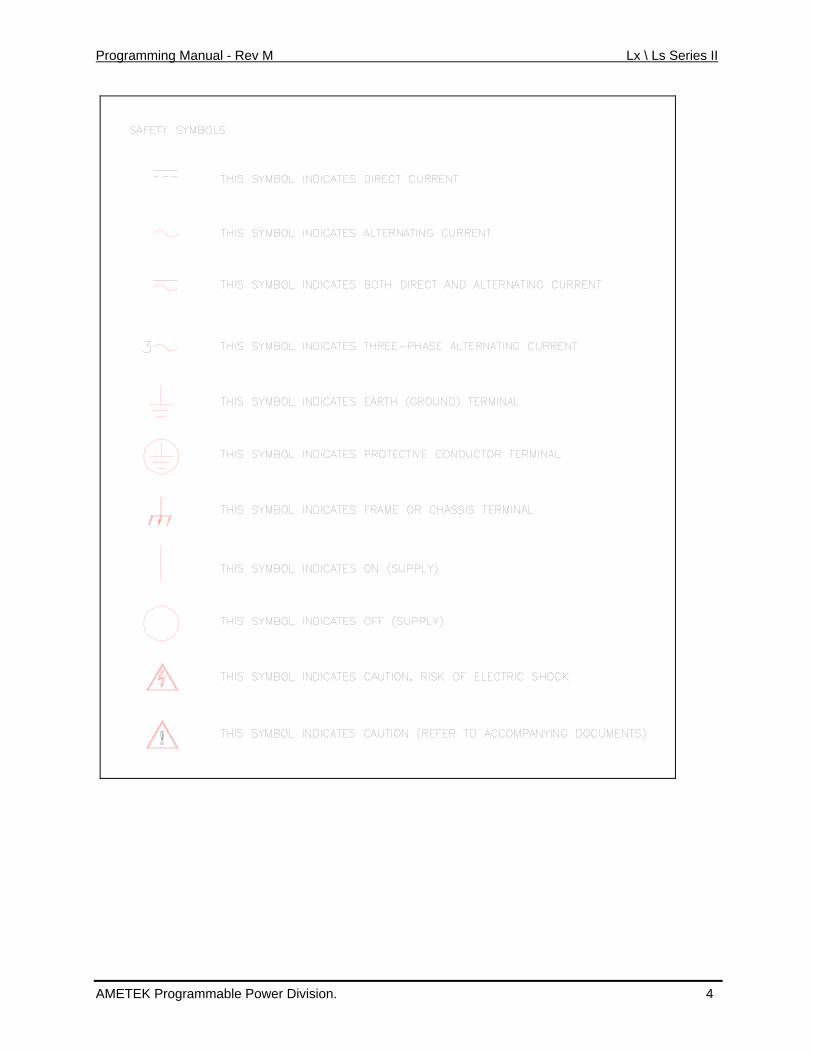
SAFETY SUMMARY This power source contains high voltage and current circuits, which are potentially lethal. Because of its size and weight, mechanical stability must be ensured. The following safety guidelines must be followed when operating or servicing this equipment. These guidelines are not a substitute for vigilance and common sense. AMETEK Programmable Power Division assumes no liability for the customer’s failure to comply with these requirements. If the power source is used in a manner not specified by AMETEK Programmable Power Division, the protection provided by the equipment may be impaired. BEFORE APPLYING POWER 1. Verify the correct three phase input voltage is applied to the unit. Input ratings are shown on the
model and serial number tag located at the rear of the unit. 2. The chassis and cabinet of this power source must be grounded to minimize shock hazard. A
chassis ground is provided at the input terminal block. This is located in the front of the cabinet on the lower left hand side. The lower front cover panel must be removed to access the line input and ground connections. The chassis ground must be connected to an electrical ground through an insulated wire of sufficient gauge.
FUSES Use only fuses of the specified current, voltage, and protection speed (slow blow, normal blow, fast blow) rating. Do not short out the fuse holder or use a repaired fuse.
DO NOT OPERATE IN A VOLATILE ATMOSPHERE Do not operate the power source in the presence of flammable gases or fumes.
DO NOT TOUCH ENERGIZED CIRCUITS Disconnect the power cable before servicing this equipment. Even with the power cable disconnected, high voltage can still exist on some circuits. Discharge these voltages before servicing. Only qualified service personnel may remove covers, replace components or make adjustments.
DO NOT SERVICE ALONE Do not remove covers, replace components, or make adjustments unless another person, who can administer first aid, is present.
DO NOT EXCEED INPUT RATINGS Do not exceed the rated input voltage or frequency. Additional hazards may be introduced because of component failure or improper operation.
DO NOT MODIFY INSTRUMENT OR SUBSTITUTE PARTS Do not modify this instrument or substitute any parts. Additional hazards may be introduced because of component failure or improper operation.
MOVING THE POWER SOURCE When moving the power source, observe the following:
1. Remove all AC power to unit. 2. Don not attempt to lift by hand. Raise the levelers and push the unit using two people to prevent injury or use forklift equipment with a qualified operator.
ALLOW CAPACITORS TO DISCHARGE Capacitors in the power source may hold a hazardous electrical charge even if the power source has been disconnected from the mains supply. Allow capacitors to discharge to a safe voltage before servicing internal circuits or touching exposed pins of mains supply connectors.
AMETEK Programmable Power Division. 3
Programming Manual - Rev M Lx \ Ls Series II
AMETEK Programmable Power Division. 4
Programming Manual - Rev M Lx \ Ls Series II
Table of Contents
1. Introduction .......................................................................................................................................... 8 1.1 Documentation Summary ............................................................................................................... 8 1.2 Lx Series and Ls Series Differences .............................................................................................. 9 1.3 Manual organization and format................................................................................................... 10 1.4 Introduction to Programming ........................................................................................................ 10
2. Introduction to SCPI .......................................................................................................................... 12 2.1 Conventions Used in This Manual................................................................................................ 12 2.2 The SCPI Commands and Messages .......................................................................................... 12 2.3 Using Queries............................................................................................................................... 15 2.4 Coupled Commands..................................................................................................................... 15 2.5 Structure of a SCPI Message....................................................................................................... 15 2.6 SCPI Data Formats ...................................................................................................................... 18
3. System Considerations..................................................................................................................... 20 3.1 IEEE-488 / GPIB Interface............................................................................................................ 20 3.2 USB Interface ............................................................................................................................... 21 3.3 LAN Option ................................................................................................................................... 28 3.4 RS232C Serial Interface............................................................................................................... 33 3.5 Instrument Drivers and Application Software ............................................................................... 34
4. SCPI Command Reference ............................................................................................................... 35 4.1 Introduction ................................................................................................................................... 35 4.2 Subsystem Commands ................................................................................................................ 36 4.3 Calibration Subsystem.................................................................................................................. 37 4.4 Diagnostic Subsystem.................................................................................................................. 39 4.5 Display Subsystem ....................................................................................................................... 40 4.6 Instrument Subsystem.................................................................................................................. 42 4.7 Limit Subsystem ........................................................................................................................... 43 4.8 Array Measurement Subsystem ................................................................................................... 45 4.9 Current Measurement Subsystem................................................................................................ 51 4.10 Frequency Measurement Subsystem........................................................................................... 56 4.11 Power Measurement Subsystem ................................................................................................. 57 4.12 Voltage Measurement Subsystem ............................................................................................... 59 4.13 Output Subsystem ........................................................................................................................ 62 4.14 Power On Subsystem................................................................................................................... 67 4.15 Sense Subsystem - Sweep .......................................................................................................... 69 4.16 Source Subsystem - Current ........................................................................................................ 71 4.17 Source Subsystem - Frequency ................................................................................................... 73 4.18 Source Subsystem - Function ...................................................................................................... 76 4.19 Source Subsystem - List............................................................................................................... 79 4.20 Source Subsystem - Phase.......................................................................................................... 86 4.21 Source Subsystem - Pulse ........................................................................................................... 88 4.22 Source Subsystem - Voltage........................................................................................................ 91 4.23 Status Subsystem Commands ..................................................................................................... 97 4.24 System Commands .................................................................................................................... 104 4.25 Trace Subsystem Commands .................................................................................................... 109 4.26 Trigger Subsystem ..................................................................................................................... 111
5. Common Commands....................................................................................................................... 116 5.1 *CLS ........................................................................................................................................... 117 5.2 *ESR? ......................................................................................................................................... 117 5.3 *IDN? .......................................................................................................................................... 118 5.4 *OPC........................................................................................................................................... 118 5.5 *OPT? ......................................................................................................................................... 118
AMETEK Programmable Power Division. 5
Programming Manual - Rev M Lx \ Ls Series II
5.6 *PSC ........................................................................................................................................... 118 5.7 *RCL ........................................................................................................................................... 119 5.8 *RST ........................................................................................................................................... 120 5.9 *SAV ........................................................................................................................................... 121 5.10 *SRE ........................................................................................................................................... 121 5.11 *STB? ......................................................................................................................................... 121 5.12 *TRG........................................................................................................................................... 122 5.13 *TST?.......................................................................................................................................... 122 5.14 *WAI............................................................................................................................................ 123
6. Programming Examples.................................................................................................................. 124 6.1 Introduction ................................................................................................................................. 124 6.2 Programming the Output ............................................................................................................ 124 6.3 Coupled Commands................................................................................................................... 128 6.4 Programming Output Transients ................................................................................................ 129 6.5 Step and Pulse Transients ......................................................................................................... 130 6.6 List Transients ............................................................................................................................ 132 6.7 Triggering Output Changes ........................................................................................................ 133 6.8 Making Measurements ............................................................................................................... 137 6.9 Controlling the Instantaneous Voltage and Current Data Buffers .............................................. 142 6.10 Downloading Arbitrary Waveforms............................................................................................. 146 6.11 Command Processing Times ..................................................................................................... 147
7. Programming the Status and Event Registers ............................................................................. 148 7.1 Power-On Conditions ................................................................................................................. 148 7.2 Operation Status Group.............................................................................................................. 148 7.3 Questionable Status Group ........................................................................................................ 151 7.4 Questionable Instrument Isummary Status Group ..................................................................... 152 7.5 Standard Event Status Group..................................................................................................... 153 7.6 Status Byte Register................................................................................................................... 154 7.7 Examples .................................................................................................................................... 155 7.8 Remote Inhibit and Discrete Fault Indicator ............................................................................... 158 7.9 SCPI Command Completion ...................................................................................................... 159
8. Option Commands........................................................................................................................... 160 8.1 Introduction ................................................................................................................................. 160 8.2 APE Command Language (Abbreviated Plain English) ............................................................. 161 8.3 ABLE Command Language (Atlas Based Language Extension)............................................... 181 8.4 RTCA/DO-160D (-160) ............................................................................................................... 186 8.5 RTCA/DO160 Rev E Test Option............................................................................................... 193 8.6 MIL-STD 704 Rev D - F (-704) ................................................................................................... 194 8.7 MIL-STD 704 Rev A - F (-704F) ................................................................................................. 200 8.8 Airbus ABD0100.1.8 Test Option (-ABD) ................................................................................... 216 8.9 Airbus A350, ABD0100.1.8.1 Test Option (-A350)..................................................................... 216 8.10 Airbus AMD24 Test Option (-AMD) ............................................................................................ 216 8.11 Boeing 787B3-0147 Test Option (-B787) ................................................................................... 216
Appendix A: SCPI Command tree ......................................................................................................... 217 Appendix B: SCPI Conformance Information ...................................................................................... 221 Appendix C: Error Messages................................................................................................................. 224 Appendix D: iL Series / HP6834B Compatability ................................................................................ 230 Index 232
AMETEK Programmable Power Division. 6
Programming Manual - Rev M Lx \ Ls Series II
Table of Figures Figure 2-1: Partial Command Tree ............................................................................................................. 13 Figure 2-2: Command Message Structure.................................................................................................. 16 Figure 3-1: Windows XP Device Manager - USB Port ............................................................................... 26 Figure 3-2: LxGui Interface Settings for use of USB port. .......................................................................... 27 Figure 3-3: Pinging AC Source LAN IP address......................................................................................... 31 Figure 3-4: Position of LAN/RS232C selection jumper W2 on 7004-716-2 Range/Relay board. .............. 33 Figure 6-1: Model of transient system....................................................................................................... 130 Figure 6-2: Model of output trigger system. .............................................................................................. 134 Figure 6-3: Model of Measurement triggers.............................................................................................. 140 Figure 6-4: Pre- and Post Event Triggering. ............................................................................................. 145 Figure 7-1: Status Register Model. ........................................................................................................... 149 Figure 7-2: SMA Connector Trigger Model............................................................................................... 157 Figure 8-1: APE Command Tree .............................................................................................................. 167
Table of Tables
Table 2-1: Command parameters Suffixes and Multipliers......................................................................... 18 Table 3-1: LAN Setting screens. ................................................................................................................. 31 Table 4-1: PULSe:HOLD = WIDTh parameters......................................................................................... 89 Table 4-2: PULSe:HOLD = DCYCle parameters........................................................................................ 89 Table 4-3: Bit Configuration of Status Operation Registers........................................................................ 98 Table 4-4: Bit Configuration of Questionable Registers ............................................................................. 99 Table 4-5: Bit Configuration of Questionable Instrument Summary Registers......................................... 101 Table 5-1: Bit Configuration of Standard Event Status Enable Register .................................................. 117 Table 5-2 : factory-defined *RST states.................................................................................................... 120 Table 5-3: Bit Configuration of Status Byte Register ................................................................................ 122 Table 6-1: Command Processing Times. ................................................................................................. 147 Table 7-1: Operation Status registers....................................................................................................... 148 Table 7-2: Bit Configurations of Status Registers..................................................................................... 150 Table 7-3: Questionable Status registers ................................................................................................. 151 Table 7-4: Questionable Instrument Isummary Status registers .............................................................. 152 Table 8-1: APE to SCPI mode change commands................................................................................... 161 Table 8-2: APE versus SCPI equivalent power initialization commands.................................................. 163 Table 8-3: APE language syntax program headers.................................................................................. 169 Table 8-4: APE Language TLK Arguments .............................................................................................. 171 Table 8-5: Example TALK responses for 3 phase systems...................................................................... 177 Table 8-6: APE Status Byte Error Codes.................................................................................................. 179 Table 8-7: ABLE to SCPI mode change commands................................................................................. 181 Table 8-8: ABLE languange synstax (-ABL option) .................................................................................. 184 Table 8-9: ABLE languange - Serial Poll Status Bytes. ............................................................................ 185 Table 8-10: MS704 Steady state frequency by group .............................................................................. 203 Table 8-11: SCPI error codes and messages........................................................................................... 229
AMETEK Programmable Power Division. 7
Programming Manual - Rev M Lx \ Ls Series II
1. Introduction This instruction manual (P/N 7004-981) contains programming informationfor the Lx Series II and Ls Series II AC power sources. The Series II versions of the Lx and Ls Series are backward compatible with the Series I models. The Programming Manual for Series I models is CI P/N 7004-961 and is available for download at www.calinst.com.
Series II models are different from the original Lx/Ls Series in the following areas:
• Standard USB interface has been added.
• Available 100Mbit Ethernet LAN interface has been added. (Option –LAN).
• The front panel graphic design has been enhanced for a more pleasing look.
• The Output D and E terminal block is no longer installed on the standard Lx and Ls units unless the auxiliary output option –AX is installed. This makes the standard output terminal block more easily accessible.
No other functional differences exist between the Series I and Series II AC power sources. The RS232C interface is still available in addition to the USB interface.
The expression "AC source" as used in the manual also applies to the same series. You will find the following information in the rest of this manual:
Chapter 2 Introduction to SCPI Chapter 3 System Considerations Chapter 4 SCPI Command Reference Chapter 5 Common Commands Chapter 6 Programming Examples Chapter 7 Programming the Status and Event Registers Chapter 8 Options Appendix A SCPI command tree Appendix B SCPI conformance information Appendix C Error messages
1.1 Documentation Summary
The following document is related to this Programming Manual and may have additional helpful information for using the AC source.
• User's Manual. P/N 7004-980 Includes specifications and supplemental characteristics, how to use the front panel, how to connect to the instrument, and calibration procedures.
1.1.1 External References
SCPI References
The following documents will assist you with programming in SCPI:
• Beginner's Manual to SCPI. Highly recommended for anyone who has not had previous experience programming with SCPI.
• Controller programming manuals: consult the documentation supplied with the IEEE-488 controller or IEEE-488 PC plug in card for information concerning general IEEE-488.2 conventions and concepts.
AMETEK Programmable Power Division. 8
Programming Manual - Rev M Lx \ Ls Series II
The following are two formal documents concerning the IEEE-488 interface:
• ANSI/IEEE Std. 488.1-1987 IEEE Standard Digital Interface for Programmable Instrumentation. Defines the technical details of the IEEE-488 interface. While much of the information is beyond the need of most programmers, it can serve to clarify terms used in this manual and in related documents.
• ANSI/IEEE Std. 488.2-1987 IEEE Standard Codes, Formats, Protocols, and Common Commands. Recommended as a reference only if you intend to do fairly sophisticated programming. Helpful for finding precise definitions of certain types of SCPI message formats, data types, or common commands.
The above two documents are available from the IEEE (Institute of Electrical and Electronics Engineers), 345 East 47th Street, New York, NY 10017, USA or via the web at www.ieee.org .
1.2 Lx Series and Ls Series Differences
The Lx Series and Ls Series of AC power sources are both based on the same AC power source hardware platform and share many common components. The differences are primarily in configuration and options. This manual covers both model series. Some commands listed may not apply to Ls Series AC sources without the –ADV option and / or –MODE option.
1.2.1 Firmware differences
The Lx Series is fully featured and supports all commands listed in the programming manual.
The Ls Series provides most basic functions in its standard configurations. More advanced features can be added by specifying the –ADV (advanced) option. If the –ADV option is installed, all commands listed in this programming manual are supported. If not, commands related to arbitrary waveforms and harmonic analysis measurements are not supported and will generate a “-113 Syntax Error” message.
1.2.2 Hardware differences
In addition to the firmware differences described, the following hardware differences exist between the standard Lx Ac source and the Ls AC source.
• Lx has a 150V / 300 V rms output range pair. Optional ranges of 135/270 (-HV option) and 200/400 (-EHV option) are available at time of order.
• Ls has a 135 V / 270 V rms output range pair. Optional ranges of 156/312 (-HV option) and 200/400 (-EHV option) are available at time of order.
• The Lx rear panel connector labeling is compliant with the California Instruments iL Series which it replaces and the HP/Agilent model 6834B.
• The Ls rear panel connector labeling is compliant with the California Instruments L Series.
• The Lx Series II comes standard with both GPIB, USB and RS232C interfaces. An optional Ethernet interface (-LAN option) is available.
• The Ls Series II comes standard with USB and RS232C only. An optional GPIB interface (-GPIB option) and Ethernet interface (-LAN option) is available.
Note: Both interfaces use the SCPI command syntax as described in the programming manual.
• The Lx Series provides both three phase and single phase output modes which can be selected from the front panel or over the bus.
AMETEK Programmable Power Division. 9

Programming Manual - Rev M Lx \ Ls Series II
• The Ls Series provides either three phase (-3 models) or single phase (-1 models). Three phase Ls Series sources may optionally be equipped with the –MODE option which provides the same phase mode switching as the Lx Series.
1.3 Manual organization and format
All user documentation for AMETEK Programmable Power Division power sources is provided on CDROM in electronic format. (Adobe Portable Document Format) The required Adobe PDF viewer is supplied on the same CDROM. This manual may be printed for personal use if a hardcopy is desired. To request a hardcopy from AMETEK Programmable Power Division, contact customer service at [email protected]. There will be an additional charge for printed manuals.
This manual contains sections on programming the Lx or Ls Series over the bus. The Lx Series is equipped with GPIB, USB and RS232C interfaces. The Ls Series is equipped with a USB and RS232C interface. An optional GPIB interface can be specified at the time of order. Refer to the Lx / Ls Series User manual for information on using the remote control interface and command syntax. The user manual (P/N 7004-980) is provided on the same CDROM as this user manual.
AMETEK Programmable Power Division may make updated versions of this manual available from time to time in electronic format through it’s website. To obtain an updated manual revision if available, check the California Instruments Manual download page at www.california-instruments.com. You need to register as a customer to obtain free access to manual and software downloads.
1.4 Introduction to Programming
This section provides some general information regarding programming instrumentation and available interface types.
1.4.1 IEEE-488 Capabilities of the AC source
All AC source functions except for setting the IEEE-488 address are programmable over the IEEE-488. The IEEE 488.2 capabilities of the AC source are listed in Chapter 2 of the User's Manual. The Lx Series offers standard IEEE-488 interface. The Ls Series requires the –GPIB option.
The AC source operates from an IEEE-488 address that is set from the front panel. To set the IEEE-488 address, press the MENU key on the front panel repeatedly until the CONFIGURATION entry is shown on the LCD display.
Move the indicator on the right hand side of the display to point to CONFIGURATION and press the ENTER key.
This will display the IEEE ADRRESS currently set. To change the address, use the Voltage knob to increment or decrement the value. Press the ENTER key to confirm your selection.
To set up the GPIB/IEEE-488 interface on a Windows XP PC, refer to section 3.1, “IEEE-488 / GPIB Interface”.
AMETEK Programmable Power Division. 10
Programming Manual - Rev M Lx \ Ls Series II
1.4.2 USB Capabilities of the AC source
All AC source functions are programmable over the USB interface. The USB capabilities of the AC source are listed in Chapter 2 of the User's Manual. Some capabilities support on the GPIB interface such as ATN, GET and SRQ interrupts do not apply to the USB interface. The USB interface operates internally at a fixed baudrate of 460800 baud but USB 2.0 burst transfer rates are supported.
To set up the USB interface on a Windows XP PC, refer to section 3.2, “ USB Interface”.
The USB interface may be used to install updated firmware for the Lx / Ls controller if needed. Firmware updates and a Flash Loader utility program and instructions are available from the AMETEK Programmable Power Division website for this purpose. (www.california-instruments.com )
Multiple USB connections to same PC:
The Windows driver used to interface to the power source’s USB port emulates a serial com port. This virtual com port driver is unable to reliable differentiate between multiple units however so the use of more than one AC power source connected to the same PC via USB is not recommended. Use of the GPIB interface is recommended for these situations.
1.4.3 LAN Capabilities of the AC source
All AC source functions are programmable over the LAN (Ethernet) interface if the –LAN option is installed. The LAN capabilities of the AC source are listed in Chapter 2 of the User's Manual. Some capabilities support on the GPIB interface such as ATN, GET and SRQ interrupts do not apply to the LAN interface. The LAN interface operates internally at a fixed baudrate of 460800 baud but autodetection of 10Base-T, 100Base-T and 1000Base-T is supported.
To set up the LAN interface on a Windows XP PC, refer to section 3.3, “LAN Option”.
1.4.4 RS232C Capabilities of the AC source
All AC source functions are programmable over the RS232C interface. The RS232C capabilities of the AC source are listed in Chapter 2 of the User's Manual. Some capabilities support on the GPIB interface such as ATN, GET and SRQ interrupts do not apply to the RS232C interface. Baudrates from 9600 to 115200 are supported.
To set up the RS232C interface, refer to section 3.4, “RS232C Serial Interface”.
The RS232C interface may be used to install updated firmware for the Lx / Ls controller if needed. Firmware updates and a Flash Loader utility program and instructions are available from the AMETEK Programmable Power Division website for this purpose. (www.calinst.com )
AMETEK Programmable Power Division. 11
Programming Manual - Rev M Lx \ Ls Series II
2. Introduction to SCPI SCPI (Standard Commands for Programmable Instruments) is a programming language for controlling instrument functions over the IEEE-488. SCPI is layered on top of the hardware-portion of IEEE 488.2. The same SCPI commands and parameters control the same functions in different classes of instruments.
2.1 Conventions Used in This Manual
Angle brackets <> Items within angle brackets are parameter abbreviations. For example, <NR1> indicates a specific form of numerical data.
Vertical bar | Vertical bars separate alternative parameters. For example, NORM | TEXT indicates that either "TEXT" or "NORM" can be used as a parameter.
Square Brackets [] Items within square brackets are optional. The representation [SOURce:]LIST means that SOURce: may be omitted.
Braces {} Braces indicate parameters that may be repeated zero or more times. It is used especially for showing arrays. The notation <A> <,B> shows that parameter "A" must be entered, while parameter "B" may be omitted or may be entered one or more times.
2.2 The SCPI Commands and Messages
2.2.1 Types of SCPI Commands
SCPI has two types of commands, common and subsystem.
• Common commands generally are not related to specific operation but to
controlling overall AC source functions, such as reset, status, and synchronization. All common commands consist of a three-letter mnemonic preceded by an asterisk: *RST, *IDN?, *SRE 8
• Subsystem commands perform specific AC source functions. They are organized
into an inverted tree structure with the "root" at the top. Some are single commands while others are grouped within specific subsystems.
Refer to appendix A for the AC source SCPI tree structure.
2.2.2 Types of SCPI Messages
There are two types of SCPI messages, program and response.
• A program message consists of one or more properly formatted SCPI commands sent from the controller to the AC source. The message, which may be sent at any time, requests the AC source to perform some action.
• A response message consists of data in a specific SCPI format sent from the AC source to the controller. The AC source sends the message only when commanded by a program message called a "query."
AMETEK Programmable Power Division. 12
Programming Manual - Rev M Lx \ Ls Series II
2.2.3 The SCPI Command Tree
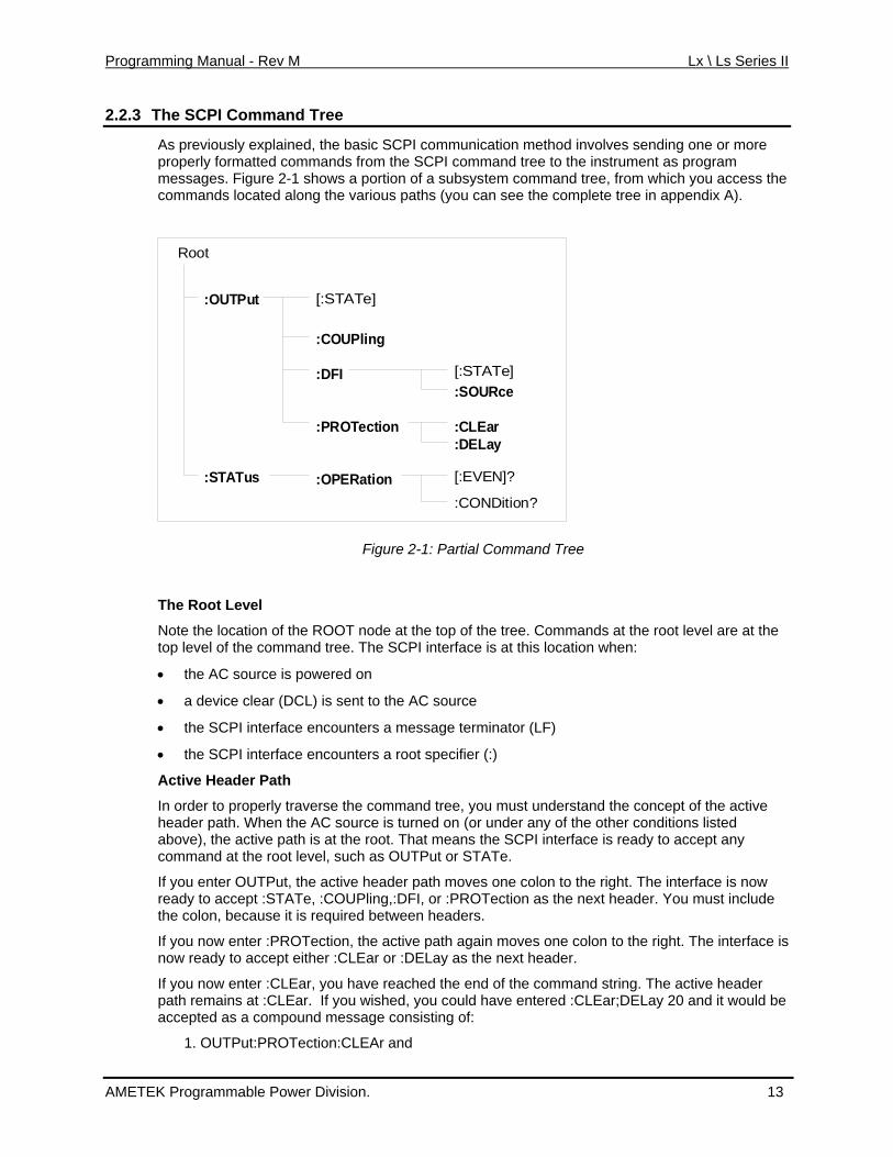
As previously explained, the basic SCPI communication method involves sending one or more properly formatted commands from the SCPI command tree to the instrument as program messages. Figure 2-1 shows a portion of a subsystem command tree, from which you access the commands located along the various paths (you can see the complete tree in appendix A).
Root
:OUTPut
:COUPling
:DFI
:PROTection
:OPERation
:SOURce
:CLEar:DELay
:STATus
[:STATe]
[:STATe]
[:EVEN]?
:CONDition?
Figure 2-1: Partial Command Tree
The Root Level
Note the location of the ROOT node at the top of the tree. Commands at the root level are at the top level of the command tree. The SCPI interface is at this location when:
• the AC source is powered on
• a device clear (DCL) is sent to the AC source
• the SCPI interface encounters a message terminator (LF)
• the SCPI interface encounters a root specifier (:)
Active Header Path
In order to properly traverse the command tree, you must understand the concept of the active header path. When the AC source is turned on (or under any of the other conditions listed above), the active path is at the root. That means the SCPI interface is ready to accept any command at the root level, such as OUTPut or STATe.
If you enter OUTPut, the active header path moves one colon to the right. The interface is now ready to accept :STATe, :COUPling,:DFI, or :PROTection as the next header. You must include the colon, because it is required between headers.
If you now enter :PROTection, the active path again moves one colon to the right. The interface is now ready to accept either :CLEar or :DELay as the next header.
If you now enter :CLEar, you have reached the end of the command string. The active header path remains at :CLEar. If you wished, you could have entered :CLEar;DELay 20 and it would be accepted as a compound message consisting of:
1. OUTPut:PROTection:CLEAr and
AMETEK Programmable Power Division. 13
Programming Manual - Rev M Lx \ Ls Series II
2. OUTPut:PROTection:DELay 20.
The entire message would be:
OUTPut:PROTection:CLEar;DELay 20
The message terminator after DELay 20 returns the path to the root.
The Effect of Optional Headers
If a command includes optional headers, the interface assumes they are there. For example, if you enter OUTPut OFF, the interface recognizes it as OUTPut:STATe OFF. This returns the active path to the root (:OUTPut). But if you enter OUTPut:STATe OFF, then the active path remains at :STATe. This allows you to send
OUTPut:STATe OFF;PROTection:CLEar
in one message. If you tried to send
OUTPut OFF;PROTection:CLEar
the header path would return to :OUTPut instead of :PROTection.
The optional header [SOURce] precedes the current, frequency, function, phase, pulse, list, and voltage subsystems. This effectively makes :CURRent,:FREQuency, :FUNCtion, :PHASe, :PULse, :LIST, and :VOLTage root-level commands.
Moving Among Subsystems
In order to combine commands from different subsystems, you need to be able to restore the active path to the root. You do this with the root specifier (:). For example, you could clear the output protection and check the status of the Operation Condition register as follows:
OUTPut:PROTection:CLEAr
STATus:OPERation:CONDition?
Because the root specifier resets the command parser to the root, you can use the root specifier and do the same thing in one message:
OUTPut:PROTection:CLEAr;:STATus:OPERation:CONDition?
The following message shows how to combine commands from different subsystems as well as within the same subsystem:
VOLTage:LEVel 70;PROTection 80;:CURRent:LEVel 3;PROTection:STATe ON
Note the use of the optional header LEVel to maintain the correct path within the voltage and current subsystems and the use of the root specifier to move between subsystems.
Note: The "Enhanced Tree Walking Implementation" given in appendix A of the IEEE 488.2 standard is not implemented in the AC source.
Including Common Commands You can combine common commands with system commands in the same message. Treat the common command as a message unit by separating it with a semicolon (the message unit separator). Common commands do not affect the active header path; you may insert them anywhere in the message.
VOLTage:TRIGger 7.5;INITialize;*TRG
OUTPut OFF;*RCL 2;OUTPut ON
AMETEK Programmable Power Division. 14
Programming Manual - Rev M Lx \ Ls Series II
2.3 Using Queries
Observe the following precautions with queries:
• Set up the proper number of variables for the returned data.
• Read back all the results of a query before sending another command to the AC source. Otherwise a Query Interrupted error will occur and the unreturned data will be lost.
2.4 Coupled Commands
When commands are coupled it means that the value sent by one command is affected by the settings of the other commands. The following commands are coupled in the AC source:
• the voltage and function shape commands
• the step, pulse, and list commands that control output voltages and function shapes
• the pulse commands that program the width, duty cycle, period, and the hold parameter
• the voltage range and current limit commands
As explained later in chapter 4, the order in which data is sent by these coupled commands can be important when more than one parameter is changed.
2.5 Structure of a SCPI Message
SCPI messages consist of one or more message units ending in a message terminator. The terminator is not part of the syntax, but implicit in the way your programming language indicates the end of a line (such as a newline or end-of-line character).
2.5.1 The Message Unit
The simplest SCPI command is a single message unit consisting of a command header (or keyword) followed by a message terminator.
ABORt<newline>
VOLTage?<newline>
The message unit may include a parameter after the header. The parameter usually is numeric, but it can be a string:
VOLTage 20<newline>
VOLTage MAX<newline>
2.5.2 Combining Message Units
The following command message is briefly described here, with details in subsequent paragraphs.
AMETEK Programmable Power Division. 15
Programming Manual - Rev M Lx \ Ls Series II
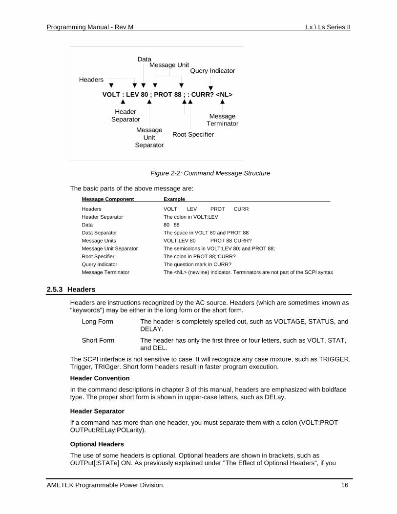
VOLT : LEV 80 ; PROT 88 ; : CURR? <NL>
Headers
DataMessage Unit
Query Indicator
HeaderSeparator
MessageUnit
SeparatorRoot Specifier
MessageTerminator
Figure 2-2: Command Message Structure
The basic parts of the above message are: Message Component Example
Headers VOLT LEV PROT CURR Header Separator The colon in VOLT:LEV Data 80 88 Data Separator The space in VOLT 80 and PROT 88 Message Units VOLT:LEV 80 PROT 88 CURR? Message Unit Separator The semicolons in VOLT:LEV 80; and PROT 88; Root Specifier The colon in PROT 88;:CURR? Query Indicator The question mark in CURR? Message Terminator The <NL> (newline) indicator. Terminators are not part of the SCPI syntax
2.5.3 Headers
Headers are instructions recognized by the AC source. Headers (which are sometimes known as "keywords") may be either in the long form or the short form.
Long Form The header is completely spelled out, such as VOLTAGE, STATUS, and DELAY.
Short Form The header has only the first three or four letters, such as VOLT, STAT, and DEL.
The SCPI interface is not sensitive to case. It will recognize any case mixture, such as TRIGGER, Trigger, TRIGger. Short form headers result in faster program execution.
Header Convention
In the command descriptions in chapter 3 of this manual, headers are emphasized with boldface type. The proper short form is shown in upper-case letters, such as DELay.
Header Separator
If a command has more than one header, you must separate them with a colon (VOLT:PROT OUTPut:RELay:POLarity).
Optional Headers
The use of some headers is optional. Optional headers are shown in brackets, such as OUTPut[:STATe] ON. As previously explained under "The Effect of Optional Headers", if you
AMETEK Programmable Power Division. 16
Programming Manual - Rev M Lx \ Ls Series II
combine two or more message units into a compound message, you may need to enter the optional header.
2.5.4 Query Indicator
Following a header with a question mark turns it into a query (VOLTage?, VOLTage:PROTection?). If a query contains a parameter, place the query indicator at the end of the last header (VOLTage:PROTection? MAX).
2.5.5 Message Unit Separator
When two or more message units are combined into a compound message, separate the units with a semicolon (STATus:OPERation?;QUEStionable?).
2.5.6 Root Specifier
When it precedes the first header of a message unit, the colon becomes the root specifier. It tells the command parser that this is the root or the top node of the command tree. Note the difference between root specifiers and header separators in the following examples:
OUTPut:PROTection:DELay .1 All colons are header separators
:OUTPut:PROTection:DELay .1 Only the first colon is a root specifier
OUTPut:PROTection:DELay .1;:VOLTage 12.5 Only the third colon is a root specifier
Note: You do not have to precede root-level commands with a colon; there is an implied colon in front of every root-level command.
2.5.7 Message Terminator
A terminator informs SCPI that it has reached the end of a message. Three permitted messages terminators are:
• newline (<NL>), which is ASCII decimal 10 or hex 0A.
• end or identify (<END>)
• both of the above (<NL><END>).
In the examples of this manual, there is an assumed message terminator at the end of each message. If the terminator needs to be shown, it is indicated as <NL> regardless of the actual terminator character.
AMETEK Programmable Power Division. 17
Programming Manual - Rev M Lx \ Ls Series II
2.6 SCPI Data Formats
All data programmed to or returned from the AC source is ASCII. The data may be numerical or character string.
2.6.1 Numerical Data Formats
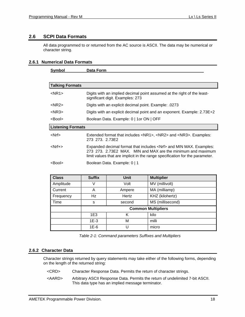
Symbol Data Form
Talking Formats
<NR1> Digits with an implied decimal point assumed at the right of the least-significant digit. Examples: 273
<NR2> Digits with an explicit decimal point. Example: .0273
<NR3> Digits with an explicit decimal point and an exponent. Example: 2.73E+2
<Bool> Boolean Data. Example: 0 | 1or ON | OFF
Listening Formats
<Nrf> Extended format that includes <NR1>, <NR2> and <NR3>. Examples: 273 273. 2.73E2
<Nrf+> Expanded decimal format that includes <Nrf> and MIN MAX. Examples: 273 273. 2.73E2 MAX. MIN and MAX are the minimum and maximum limit values that are implicit in the range specification for the parameter.
<Bool> Boolean Data. Example: 0 | 1
Class Suffix Unit Multiplier Amplitude V Volt MV (millivolt) Current A Ampere MA (milliamp) Frequency Hz Hertz KHZ (kilohertz) Time s second MS (millisecond) Common Multipliers 1E3 K kilo 1E-3 M milli 1E-6 U micro
Table 2-1: Command parameters Suffixes and Multipliers
2.6.2 Character Data
Character strings returned by query statements may take either of the following forms, depending on the length of the returned string:
<CRD> Character Response Data. Permits the return of character strings.
<AARD> Arbitrary ASCII Response Data. Permits the return of undelimited 7-bit ASCII. This data type has an implied message terminator.
AMETEK Programmable Power Division. 18

Programming Manual - Rev M Lx \ Ls Series II
<SRD> String Response Data. Returns string parameters enclosed in double quotes.
AMETEK Programmable Power Division. 19
Programming Manual - Rev M Lx \ Ls Series II
3. System Considerations This chapter addresses some system issues concerning setting up interfaces such as GPIB, USB or Ethernet.
3.1 IEEE-488 / GPIB Interface
All Lx Series power sources are equipped with an industry standard IEEE-488.2 interface (GPIB). On Ls models, the IEEE-488.2 interface is available as an option (Option –GPIB).
A GPIB controller such as a Windows PC with suitable GPIB controller card is required to use the GPIB interface.
3.1.1 Assigning the IEEE-488 Address
The AC source address cannot be set remotely. It must be set from the front panel. Once the address is set, you can assign it inside programs. The GPIB address can be set/changed from the CONFIGURATION menu screen. Press the MENU key and scroll to the CONFIGURATION menu using the Up/Down arrow keys or press the MENU key repeatedly until the CONFIGURATION screen appears. Press the ENTER key to enter the CONFIGURATION screen.
Scroll to the ADDRESS field using the Up/Down arrow keys on the front panel. The value of the ADDRESS can be set from 0 through 31. Avoid using address 0 as it is generally reserved for the GPIB bus controller. Once set, the GPIB address of the power source is retained in non-volatile memory.
For systems using the National Instruments VISA or IVI drivers, the address is specified in the resource descriptor (GPIB::1). Consult you programmer’s reference documentation on how to address a GPIB instrument using your specific GPIB controller’s function library.
3.1.2 LxGui and IEEE-488
The provided Windows LxGui program supports the GPIB interface on both Lx Series and Ls Series models but only in combination with a National Instruments GPIB controller. The default controller ID is zero but controller ID’s from 0 thorugh 3 can be selected in the LxGui Interface screen if multiple GPIB controllers are present in the same PC. Note that the LxGui program only supports one Lx/Ls power source at a time.
AMETEK Programmable Power Division. 20
Programming Manual - Rev M Lx \ Ls Series II
3.2 USB Interface
Unlike RS232C, there are no generic drivers available as a rule for us in programming environments such as LabView, LabWindows/CVI or Visual Basic. However, support for USB is included under VISA and may be used to interface to the power source using the USB interface.
For other environments, a virtual serial port utility is provided on CD ROM CIC496 which ships with the Lx/Ls Series power source. This utility will provide a virtual COM port on a PC under Windows XP. This allows legacy programs to use the USB port as though it is a regular serial port on the PC. The baud rate for this mode of operation is fixed at 460,800. If you plan to use this feature, the USB-Serial Adaptor installation must be run to install the virtual com port driver. This option is only supported under Windows XP / Windows Vista.
3.2.1 USB Driver Installation
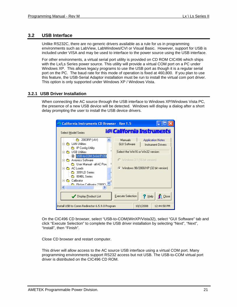
When connecting the AC source through the USB interface to Windows XP/Windows Vista PC, the presence of a new USB device will be detected. Windows will display a dialog after a short delay prompting the user to install the USB device drivers.
On the CIC496 CD browser, select “USB-to-COM(WinXP/Vista32), select “GUI Software” tab and click “Execute Selection” to complete the USB driver installation by selecting “Next”, “Next”, “Install”, then “Finish”. Close CD browser and restart computer. This driver will allow access to the AC source USB interface using a virtual COM port. Many programming environments support RS232 access but not USB. The USB-to-COM virtual port driver is distributed on the CIC496 CD ROM.
AMETEK Programmable Power Division. 21
Programming Manual - Rev M Lx \ Ls Series II
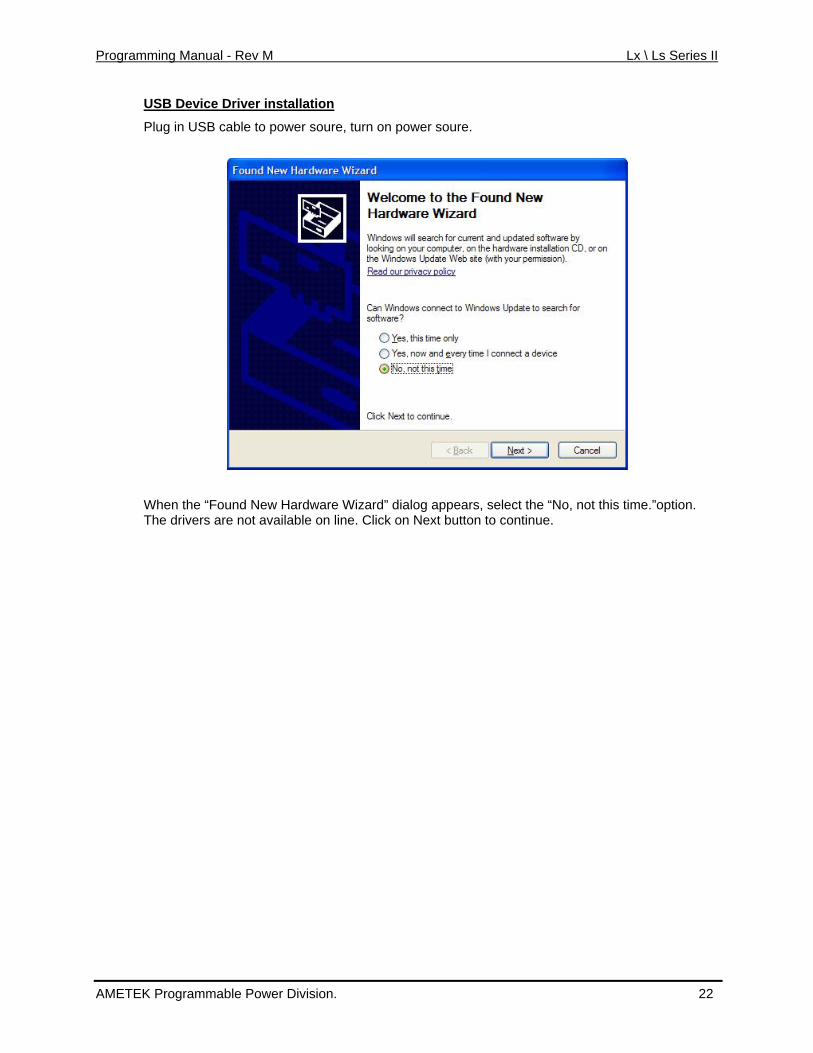
USB Device Driver installation
Plug in USB cable to power soure, turn on power soure.
When the “Found New Hardware Wizard” dialog appears, select the “No, not this time.”option. The drivers are not available on line. Click on Next button to continue.
AMETEK Programmable Power Division. 22
Programming Manual - Rev M Lx \ Ls Series II
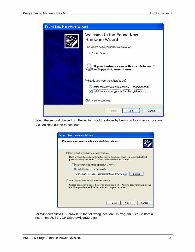
Select the second choice from the list to install the driver by browsing to a specific location.
Click on Next button to continue.
For Windows Vista OS, browse to the following location: C:\Program Files\California Instruments\USB VCP Drivers\Vista(32-bits).
AMETEK Programmable Power Division. 23
Programming Manual - Rev M Lx \ Ls Series II
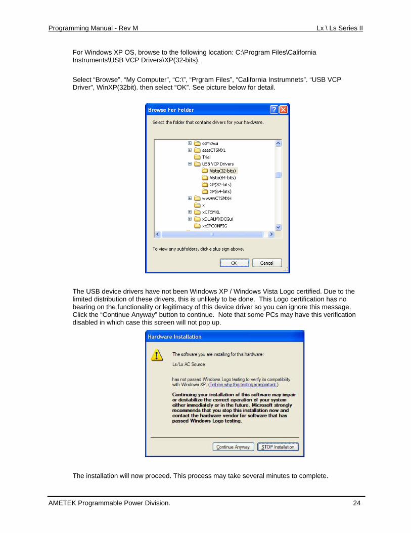
For Windows XP OS, browse to the following location: C:\Program Files\California Instruments\USB VCP Drivers\XP(32-bits). Select “Browse”, “My Computer”, “C:\”, “Prgram Files”, “California Instrumnets”. “USB VCP Driver”, WinXP(32bit). then select “OK”. See picture below for detail.
The USB device drivers have not been Windows XP / Windows Vista Logo certified. Due to the limited distribution of these drivers, this is unlikely to be done. This Logo certification has no bearing on the functionality or legitimacy of this device driver so you can ignore this message. Click the “Continue Anyway” button to continue. Note that some PCs may have this verification disabled in which case this screen will not pop up.
The installation will now proceed. This process may take several minutes to complete.
AMETEK Programmable Power Division. 24
Programming Manual - Rev M Lx \ Ls Series II
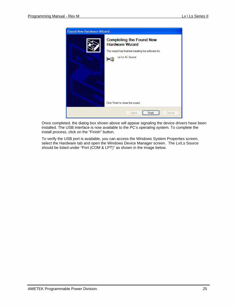
Once completed, the dialog box shown above will appear signaling the device drivers have been installed. The USB interface is now available to the PC’s operating system. To complete the install process, click on the “Finish” button.
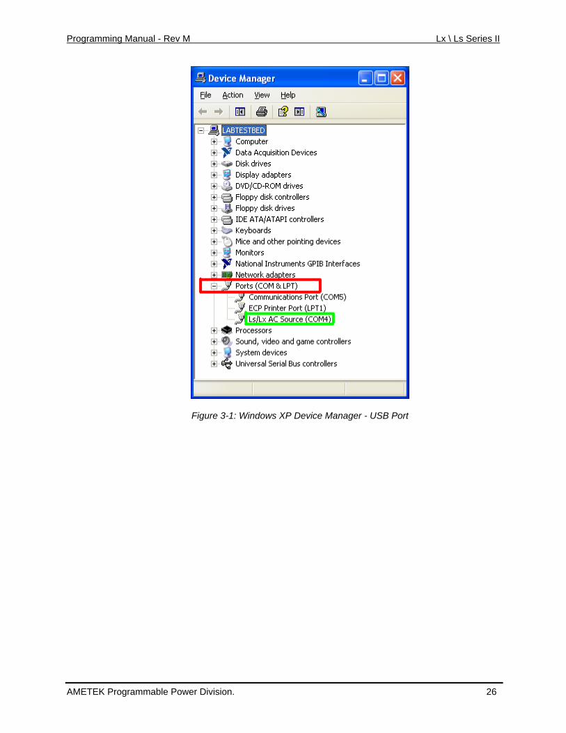
To verify the USB port is available, you can access the Windows System Properties screen, select the Hardware tab and open the Windows Device Manager screen. The Lx/Ls Source should be listed under “Port (COM & LPT)” as shown in the image below.
AMETEK Programmable Power Division. 25
Programming Manual - Rev M Lx \ Ls Series II
Figure 3-1: Windows XP Device Manager - USB Port
AMETEK Programmable Power Division. 26
Programming Manual - Rev M Lx \ Ls Series II
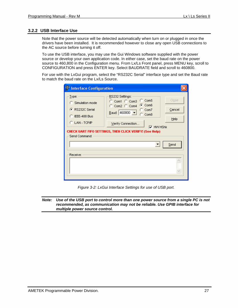
3.2.2 USB Interface Use
Note that the power source will be detected automatically when turn on or plugged in once the
ode. In either case, set the baud rate on the power
scroll to 460800.
For use with the LxGui program, select the “RS232C Serial” interface type and set the Baud rate
drivers have been installed. It is recommended however to close any open USB connections to the AC source before turning it off.
To use the USB interface, you may use the Gui Windows software supplied with the power source or develop your own application csource to 460,800 in the Configuration menu. From Lx/Ls Front panel, press MENU key, scroll to CONFIGURATION and press ENTER key. Select BAUDRATE field and
to match the baud rate on the Lx/Ls Source.
Figure 3-2: LxGui Interface Settings for use of USB port.
Note: Use of the USB port to control more than one power source from a single PC is not recommended, as communication may not be reliable. Use GPIB interface for multiple power source control.
AMETEK Programmable Power Division. 27
Programming Manual - Rev M Lx \ Ls Series II
3.3 LAN Option
An Ethernet LAN interface option is available for the Lx/Ls Series II power sources. This option must be specified at the time of order. A LAN option indicator will appear on the model numbtag at the rear-panel of the power source to indicate the presence of this option. Also, a RJ4socket will be present on the rear panel.
er 5
l proprietary software or cards.
Note: f the power source, the LAN
Using LAN lets you communicate with the instrument remotely, it is fast, simple and the LAN fromyour PC does not require any additiona
If a USB cable is plugged into the USB interface connector ointerfac e any USB connection to use the LAN / Ethernet port. e will be disabled. Remov
3.3.1 MAC Address
Each po s a unique network address (MAC address). The MA e hexadecimal address and is listed on a label on ce on a network, this MAC address needs to be assigned to a TCP/IP address which will be used to address the device o
3.3.2 TCP/IP and Gateway Address
wer source with the –LAN option installed ha address (Media Access Conrol) is a uniquC
the rear panel of the power source. To operate the power sour
n the network.
The first decision you need to make is how to connect the instrument. You can connect the instrument directly to a network LAN port with a LAN cable, or you can connect it directly to the PC. When connecting the instrument directly to the PC LAN port you will need a special cable called a cross connect cable. (For more on private network connections, see section 3.3.3) Once connected you must establish an IP address for the instrument. An IP address consists of four groups of numbers separated by a decimal. Dynamic Host Configuration Protocol (DHCP) is typically the easiest way to configure the instrument for LAN communication. DHCP automatically
s to a device on a network. To set the power source to DHCP assigns a dynamic IP addresmode, see section 3.3.4.
AMETEK Programmable Power Division. 28
Programming Manual - Rev M Lx \ Ls Series II
3.3.3 Private Networks without DHCP servers
If you are setting up a private network that connecso called cross over RJ45 cable, the PC will DH he availab address rangAuthority (IANA) for Automatic Private IP Ad 5.
When setting up a private network, you will h g off and disconnect first from any network connection and re-log in to Windows.
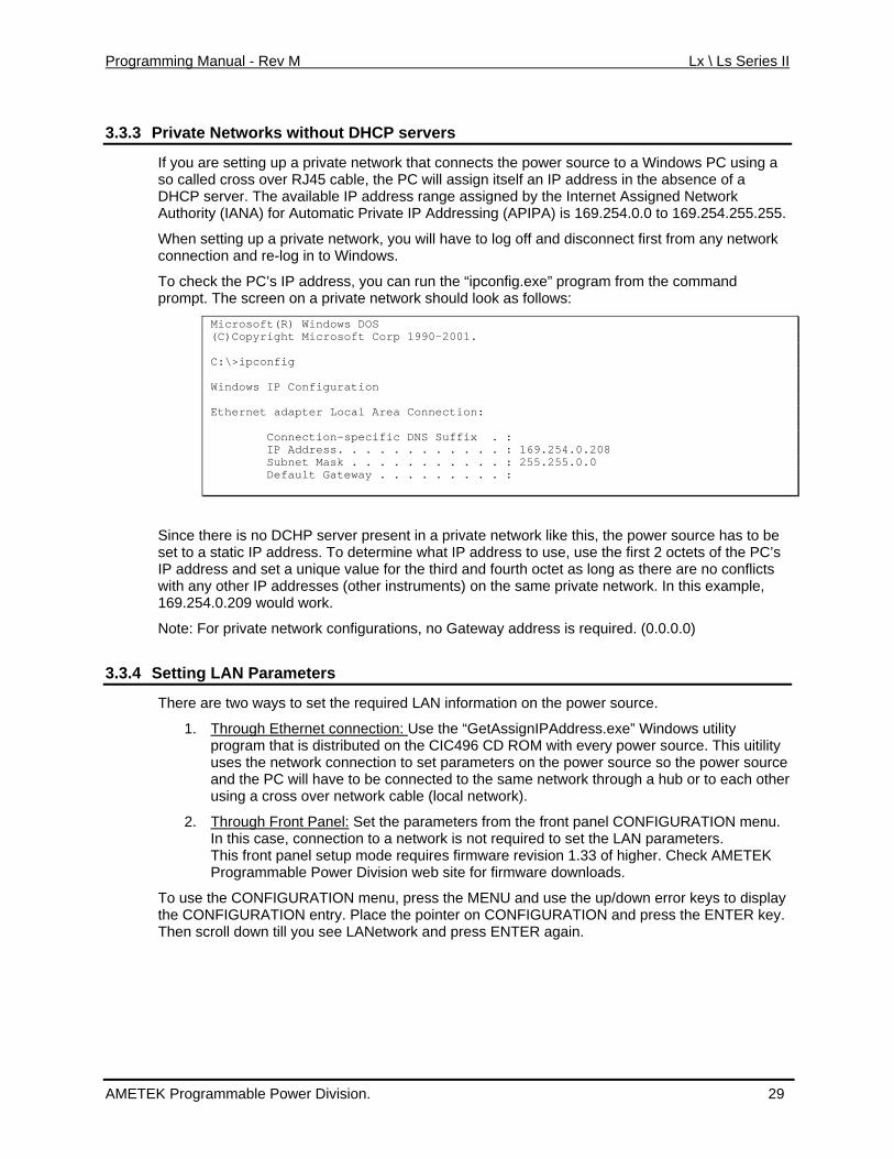
To check the PC’s IP address, you can run tprompt. The screen on a rivate network sho
Microsoft(R) Windows DOS
ts the power source to a Windows PC using a assign itself an IP address in the absence of a e assigned by the Internet Assigned Network dressing (APIPA) is 169.254.0.0 to 169.254.255.25
ave to lo
CP server. T le IP
he “ipconfig.exe” program from the command uld look as follows: p
(C)Copyright Microsoft Corp 1990-2001. C:\>ipconfig Windows IP Configuration Ethernet adapter Local Area Connection: Connection-specific DNS Suffix . : IP Address. . . . . . . . . . . . : 169.254.0.208 Subnet Mask . . . . . . . . . . . : 255.255.0.0 Default Gateway . . . . . . . . . :
Since there is no DCHP server present in a p set to a static IP address. To determine wha IP address and set a unique value for the thiwith any other IP addresses (other instrumen169.254.0.209 would work.
Note: For private network configurations, no Gateway address is required. (0.0.0.0)
3.3.4 Setting LAN Parameters
rivate network like this, the power source has to bet IP address to use, use the first 2 octets of the PC’srd and fourth octet as long as there are no conflicts ts) on the same private network. In this example,
There are two ways to set the required LAN
1. Through Ethernet connection:
information on the power source.
Use tprogram that is distributed on the CI uses the network connection to set p wer source so the power source and the PC will have to be connec er using a cross over network cable (
2. Through Front Panel:
he “GetAssignIPAddress.exe” Windows utility C496 CD ROM with every power source. This uitilityarameters on the po
ted to the same network through a hub or to each othlocal network).
Set the parameters from the front panel CONFIGURATION menu. In this case, connection to a netwoThis front panel setup mode requires firmware revision 1.33 of higher. Check AMETEK Programmable Power Division we
To use the CONFIGURATION menu, pres the CONFIGURATION entry. Place the po Then scroll down till you see LANetwork a
rk is not required to set the LAN parameters.
b site for firmware downloads.
s the MENU and use the up/down error keys to displayinter on CONFIGURATION and press the ENTER key.nd press ENTER again.
AMETEK Programmable Power Division. 29
Programming Manual - Rev M Lx \ Ls Series II
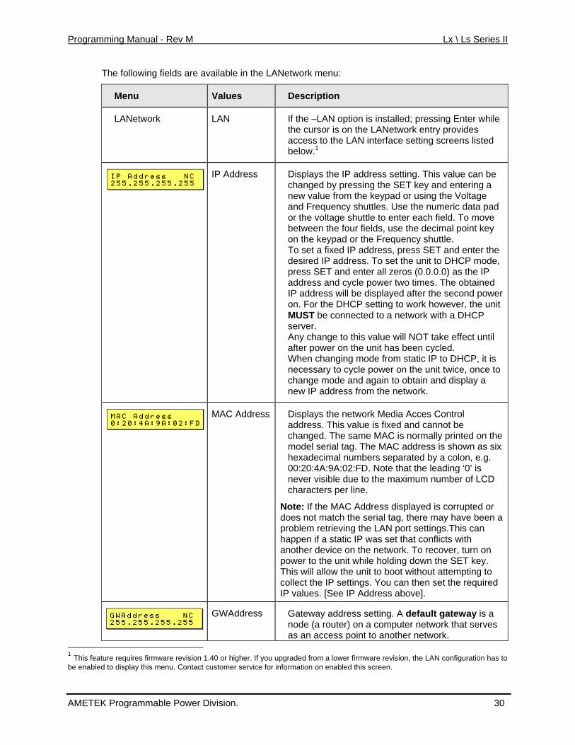
The following fields are available in the LANetwork menu:
Menu Values Description
LANetwork LAN le es
terface setting screens listed
If the –LAN option is installed; pressing Enter whithe cursor is on the LANetwork entry providaccess to the LAN inbelow.1
IP Address Displays the IP address setting. This value can be
oltage shuttle to enter each field. To move
DHCP mode, press SET and enter all zeros (0.0.0.0) as the IP
wer it
e effect until after power on the unit has been cycled.
from static IP to DHCP, it is necessary to cycle power on the unit twice, once to
changed by pressing the SET key and entering a new value from the keypad or using the Voltage and Frequency shuttles. Use the numeric data pad or the vbetween the four fields, use the decimal point keyon the keypad or the Frequency shuttle. To set a fixed IP address, press SET and enter the desired IP address. To set the unit to
address and cycle power two times. The obtained IP address will be displayed after the second poon. For the DHCP setting to work however, the unMUST be connected to a network with a DHCP server. Any change to this value will NOT tak
When changing mode
change mode and again to obtain and display a new IP address from the network.
MAC Address Displays the n
address. This etwork Media Acces Control value is fixed and cannot be
changed. The same MAC is normally printed on the model serial tag. The MAC address is shown as six hexadecimal numbers separated by a colon, e.g.
D
Note: If the MAC Address displayed is corrupted or does not match the serial tag, there may have been a
retrieving the LAN port settings.This can happen if a static IP was set that conflicts with another device on the network. To recover, turn on
unit while holding down the SET key. nit to boot without attempting to gs. You can then set the required ddress above].
00:20:4A:9A:02:FD. Note that the leading ‘0’ is never visible due to the maximum number of LCcharacters per line.
problem
power to theThis will allow the ucollect the IP settinIP values. [See IP A
GWAddress Gateway address setting. A default gateway is a uter network that serves node (a router) on a comp
as an access point to another network. 1 This feature requires firmware revision , the LAN configuration has to be enabled to display this menu. Contact customer service for information on enabled this screen.
1.40 or higher. If you upgraded from a lower firmware revision
AMETEK Programmable Power Division. 30
Programming Manual - Rev M Lx \ Ls Series II
This value can be changed by pressing the SET key and entering a new value from the keypad or
lds, use
using the Voltage and Frequency shuttles. Use the numeric data pad or the Voltage shuttle to enter each field. To move between the four fiethe decimal point key on the keypad or the Frequency shuttle. Any change to this value will NOT take effect until after power on the unit has been cycled.
HostBits Number of host bits as opposed to network bits in
network mask. A CIDR class C network uses 24 network bits and 8 host bits. (Class A = 24, Class B = 16). This value can be changed by pressing the SET key and entering a new value from the keypad. Any change to this value will NOT take effect until after power on the unit has been cycled.
Port No TCP remote port number. This value must be set to
5025 (SCPI) to support the built in web page. This value can be changed by pressing the SET key and entering a new value from the keypad. Any change to this value will NOT take effect until after power on the unit has been cycled.
Table 3-1: LAN Setting screens.
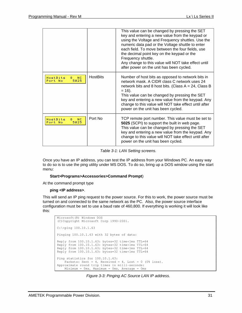
Once you have an IP address, you can test the IP address from your Windows PC. An easy way to do so is to use the ping utility under MS DOS. To do so, bring up a DOS window using the start menu:
Start>Programs>Accessories>Command Prompt)
At the command prompt type
ping <IP address>.
This will send an IP ping request to the power source. For this to work, the power source must be turned on and connected to the same network as the PC. Also, the power source interface configuration must be set to use a baud rate of 460,800. If everything is working it will look like this:
Microsoft(R) Windows DOS (C)Copyright Microsoft Corp 1990-2001. C:\>ping 100.10.1.63 Pinging 100.10.1.63 with 32 bytes of data: Reply from 100.10.1.63: bytes=32 time<1ms TTL=64 Reply from 100.10.1.63: bytes=32 time<1ms TTL=64 Reply from 100.10.1.63: bytes=32 time<1ms TTL=64 Reply from 100.10.1.63: bytes=32 time<1ms TTL=64 Ping statistics for 100.10.1.63: Packets: Sent = 4, Received = 4, Lost = 0 (0% loss), Approximate round trip times in milli-seconds: Minimum = 0ms, Maximum = 0ms, Average = 0ms
Figure 3-3: Pinging AC Source LAN IP address.
AMETEK Programmable Power Division. 31
Programming Manual - Rev M Lx \ Ls Series II
3.3.5 Socket Port Number
Now that a connection has been verified, you can develop your application code. If you are using rating
will have to specificy the port number of the power source’s LAN interface. The port number determines the protocol for the communication. The Lx/Ls power source uses
TCP Remote port = 5025
one of the Microsoft environments, the Winsock protocol which is part of the Windows opesystem can be used. Similar capabilities are supported on other operating systems.
To use Winsock, your
ASCII characters and instrument SCPI commands for remote control. The IANA registered Port number for the Instrument SCPI interface is 5025.
AMETEK Programmable Power Division. 32
Programming Manual - Rev M Lx \ Ls Series II
3.4 RS232C Serial Interface
The RS232C interface has been retained on the Lx/Ls Series II power source models for backward compatibility with the Series I products. It functions exactly like it did on the generation products.
first
Note: If a USB cable is plugged into the USB interface connector of the power source, the RS232 interface will be disabled. Remove any USB connection to use the serial port.
The RS232C interface is factory enabled for all Lx/Ls models, except those ordered with the optional –LAN interface. Models with the –LAN option have the LAN interface enabled and the RS232C port disabled.
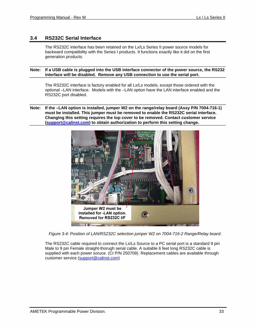
Note: If the –LAN option is installed, jumper W2 on the range/relay board (Assy P/N 7004-716-1) must be installed. This jumper must be removed to enable the RS232C serial interface. Changing this setting requires the top cover to be removed. Contact customer service ([email protected]) to obtain authorization to perform this setting change.
Figure 3-4: Position of LAN/RS232C selection jumper W2 on 7004-716-2 Range/Relay board.
The RS232C cable required to connect the Lx/Ls Source to a PC serial port is a standard 9 pin Male to 9 pin Female straight-thorugh serial cable. A suitable 6 feet long RS232C cable is supplied with each power soruce. (CI P/N 250709). Replacement cables are available through customer service ([email protected])
AMETEK Programmable Power Division. 33
Programming Manual - Rev M Lx \ Ls Series II
3.5 Instrument Drivers and Application Software
Instrument drivers for National Instruments LabWindows/CVI and LabView are generally d from the AMETEK Programmable Power Division' web site at ments.com
available for downloawww.california-instru . Also available are ready to use interactive graphical user interface (GUI) programs for download.
AMETEK Programmable Power Division. 34
Programming Manual - Rev M Lx \ Ls Series II
4. SCPI Command Reference
4.1 Introduction
This chapter provides a complete listing of all SCPI commands supported by the Lx\Ls Series of
will
Related Commands
Where appropriate, related commands or queries are included. These are listed because they are either directly related by function, or because reading about them will clarify or enhance your understanding of the original command or query.
This chapter is organized as follows:
• Subsystem commands, arranged by subsystem
• IEEE 488.2 common commands
AC sources. Commands are grouped by function according the root level commands. Some general command related issues are:
Phases
If a command can apply to individual phases of an AC source, the entry “Phase Selectable”appear in the command description.
AMETEK Programmable Power Division. 35

Programming Manual - Rev M Lx \ Ls Series II
4.2 Subsystem Commands
Subsystem commands are specific to AC source functions. They can be a single command or a comprised of commands that extend one or more levels
lo mmon commands follows the description of the subsystem
The subsystem command groups are listed in alphabetical order and the commands within each ed alphabetically under the subsystem. Commands followed by a question
ands take both the command and query form, this ax descriptions.
group of commands. The groups arebe w the root. The description of cocommands.
subsystem are groupmark (?) take only the query form. When commis noted in the synt
You will find the subsystem command groups discussed on the following pages:
AMETEK Programmable Power Division. 36
Programming Manual - Rev M Lx \ Ls Series II
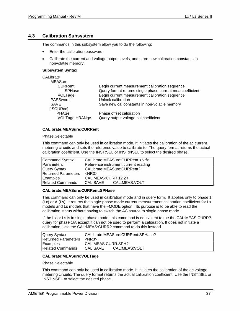
4.3 Calibration Subsystem
The commands in this ubsystems allow you to do the following:
ls, and store new calibration constants in
CALibrate
Rent ent calibration sequence ingle phase current mea coefficient.
Begin current measurement calibration sequence Unlock calibration Save new cal constants in non-volatile memory
:VOLTage:HRANge Query output voltage cal coefficient
in calibration mode. It initiates the calibration of the ac current calibrate to. The query format returns the actual
nt. Use the INST:SEL or INST:NSEL to select the desired phase.
• Enter the calibration password
• Calibrate the current and voltage output levenonvolatile memory.
Subsystem Syntax
:MEASure :CUR Begin current measurem :SPHase Query format returns s :VOLTage :PASSword :SAVE [:SOURce] PHASe Phase offset calibration
CALibrate:MEASure:CURRent
Phase Selectable
This command can only be usedmetering circuits and sets the reference value to calibration coefficie
Command Syntax CALibrate:MEASure:CURRent <Nrf> Parameters Reference instrument current reading Query Syntax CALibrate:MEASure:CURRent? Returned Paramete <NR3> rs Examples CAL:MEAS:CURR 12.23 Related Comm CAL:SAVE CAL:MEAS:VOands LT
CALibrate:MEASure:CURRent:SPHase
This command can on be usely d in calibration mode and in query form. It applies only to phase 1 e current measurement calibration coefficient for Lx
option. Its purpose is to be able to read the ithout having to switch the AC source to single phase mode.
R?
(Lx) or A (Ls). It returns the single-phase modmodels and Ls models that have the –MODEcalibration status w
If the Lx or Ls is in single phase mode, this command is equivalent to the the CAL:MEAS:CURquery for phase 1/A except it can not be used to perform a calibration. It does not initiate a calibration. Use the CAL:MEAS:CURR? command to do this instead.
Query Syntax CALibrate:MEASure:CURRent:SPHase? Returned Pa <NR3> rameters Examples CAL:MEAS:CURR:SPH? Related Commands CAL:SAVE CAL:MEAS:VOLT
CALibrate:MEASure OLTag:V e
Phase Selectable
This command can only be used in calibration mode. It initiates the calibration of the ac voltage metering circuits. The query format returns the actual calibration coefficient. Use the INST:SEL or INST:NSEL to select the desired phase.
AMETEK Programmable Power Division. 37
Programming Manual - Rev M Lx \ Ls Series II
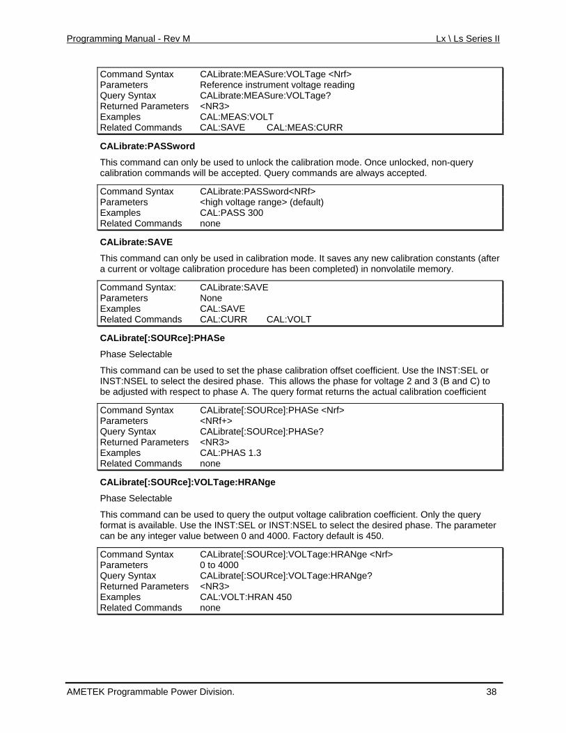
Command Syntax CALibrate:MEASure:VOLTage <Nrf> Parameters Reference instrument voltage reading Query Syntax CALibrate:MEASure:VOLTage? Returned Parameters <NR3> Examples CAL:MEAS:VOLT Related Commands CAL:SAVE CAL:MEAS:CURR
CALibrate:PASSword
ly be used to unlock the ca nlocked, non-query will be accepted. Query co
CALibrate:PASSword<NRf>
T comma libration mode. Once uhis nd can onalibratio ds c n comman mmands are always accepted.
Command Syntax Parameters <high voltage range> (default) Examples CAL:PASS 300 Related Commands none
CALibrate:SAVE
This command can o be usea current or voltage c bration
nly d in calibration mode. It saves any new calibration constants (after ali procedure has been completed) in nonvolatile memory.
E Command Syntax: CALibrate:SAVParameters None Examples CAL:SAVE Related Comm CAL:CURR CAL:VOLT ands
CALibrate[:SOURce]:PHASe
Phase Selectable
This command can be used to set the phase calibration offset coefficient. Use the INST:SEL or INST:NSEL to select the desired phase. This allows the phase for voltage 2 and 3 (B and C) to be adjusted with respect to phase A. The query format returns the actual calibration coefficient
Command Syntax CALibrate[:SOURce]:PHASe <Nrf> Parameters <NRf+> Query Syntax CALibrate[:SOURce]:PHASe? Returned Parameters <NR3> Examples CAL:PHAS 1.3 Related Commands none
CALibrate[:SOURce]:VOLTage:HRANge
Phase Selectable
This command can be used to query the output voltage calibration coefficient. Only the query format is available. Use the INST:SEL or INST:NSEL to select the desired phase. The parameter can be any integer value between 0 and 4000. Factory default is 450.
Command Syntax CALibrate[:SOURce]:VOLTage:HRANge <Nrf> Parameters 0 to 4000 Query Syntax CALibrate[:SOURce]:VOLTage:HRANge? Returned Parameters <NR3> Examples CAL:VOLT:HRAN 450 Related Commands none
AMETEK Programmable Power Division. 38
Programming Manual - Rev M Lx \ Ls Series II
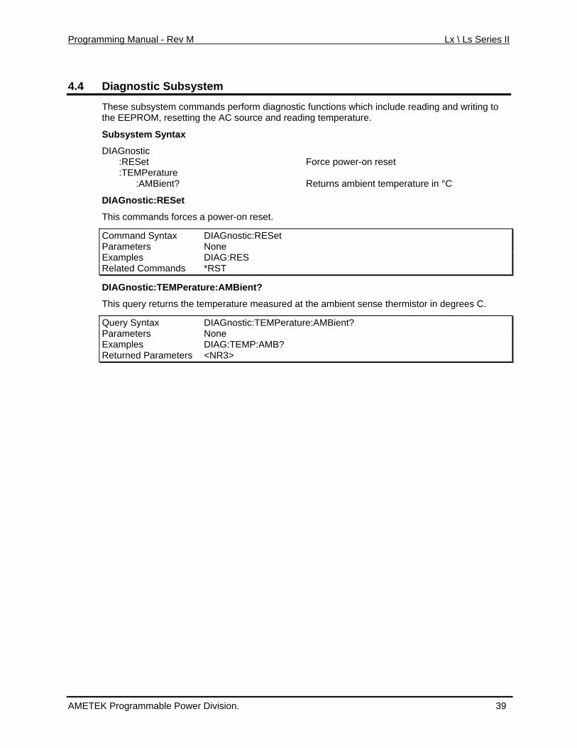
4.4 Diagnostic Subsystem
These subsystem commands perform diagnostic functions which include reading and writing the EEPROM, resetting the AC source and reading temperature.
Subsystem Sy
to
ntax
Returns ambient temperature in °C
DIAGnostic :RESet Force power-on reset :TEMPerature :AMBient?
DIAGnostic:RESet
This commands forces a power-on reset.
Command Syntax DIAGnostic:RESet Parameters None Examples DIAG:RES Related Commands *RST
DIAGnostic:TEMPerature:AMBient?
his ue the temperature measured at nse thermistor in degrees C.
DIAGnostic:TEMPeratu
T q ry returns the ambient se
Query Syntax re:AMBient? Parameters None Examples DIAG:TEMP:AMB? Returned Parameters <NR3>
AMETEK Programmable Power Division. 39
Programming Manual - Rev M Lx \ Ls Series II
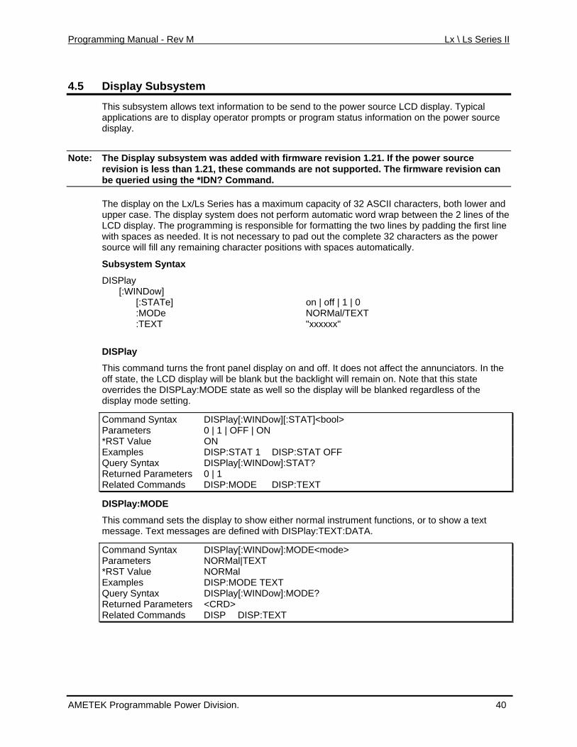
4.5 ystem Display Subs
This subsystem allows text information to be send to the power source LCD display. Typical applications are to display operator prompts or program status information on the power source display.
Note: The Display subsystem was added with firmware revision 1.21. If the power source revision is less than 1.21, these commands are not supported. The firmware revision can be queried using the *IDN? Command.
The display on the Lx/Ls Series has a maximum capahe display s not perform automatic word wrap between the 2 lines of the
city of 32 ASCII characters, both lower and upper case. T system doeLCD display. The programming is responsible for formatting the two lines by padding the first line with spaces as needed. It is not necessary to pad out the complete 32 characters as the power
utomatically.
DISPlay [:WINDow] [:STATe] on | off | 1 | 0 :MODe NORMal/TEXT :TEXT "xxxxxx"
DISPlay
This command turns the front panel display on and off. It does not affect the annunciators. In the off state, the LCD display will be blank but the backlight will remain on. Note that this state overrides the DISPLay:MODE state as well so the display will be blanked regardless of the display mode setting.
Command Syntax DISPlay[:WINDow][:STAT]<bool>
source will fill any remaining character positions with spaces a
Subsystem Syntax
Parameters 0 | 1 | OFF | ON *RST Value ON Examples DISP:STAT 1 DISP:STAT OFF Query Syntax DISPlay[:WINDow]:STAT? Returned Parameters 0 | 1 Related Commands DISP:MODE DISP:TEXT
DISPlay:MODE
This command sets the display to show either normal instrument functions, or to show a text message. Text messages are defined with DISPlay:TEXT:DATA.
Command Syntax DISPlay[:WINDow]:MODE<mode> Parameters NORMal|TEXT *RST Value NORMal Examples DISP:MODE TEXT Query Syntax DISPlay[:WINDow]:MODE? Returned Parameters <CRD> Related Commands DISP DISP:TEXT
AMETEK Programmable Power Division. 40
Programming Manual - Rev M Lx \ Ls Series II
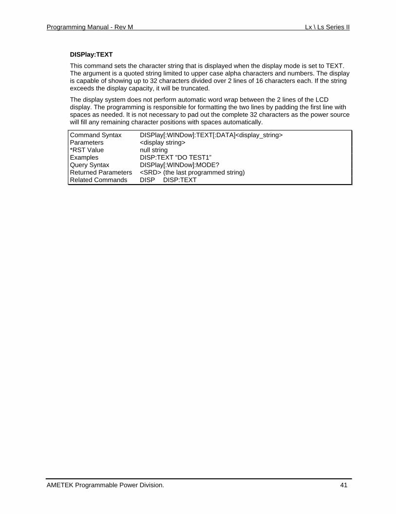
DISPlay:TEXT
This command sets the character string that is displayed when the display mode is set to TEXT. The display
up to 32 characters divided over 2 lines of 16 characters each. If the string apacity, it will be truncated.
s by padding the first line with
wer source
DISPlay[:WINDow]:TEXT[:DATA]<display_string>
The argument is a quoted string limited to upper case alpha characters and numbers. is capable of showingexceeds the display c
The display system doe not perform automatic word wrap between the 2 lines of the LCD display. The programming is responsible for formatting the two linesspaces as needed. It is not necessary to pad out the complete 32 characters as the powill fill any remaining character positions with spaces automatically.
Command Syntax Parameters <display string> *RST Value null string Examples DISP:TEXT "DO TEST1” Query Syntax DISPlay[:WINDow]:MODE? Returned Parameters <SRD> (the last programmed string) Related Commands DISP DISP:TEXT
AMETEK Programmable Power Division. 41
Programming Manual - Rev M Lx \ Ls Series II
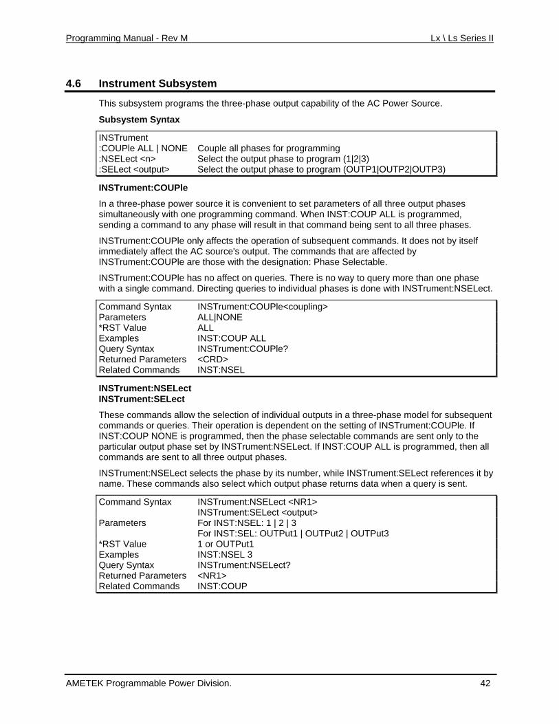
4.6 Instrument Subsystem
This subsystem programs the three-phase output capability of the AC Power Source.
Subsystem Syntax
INSTrument :COUPle ALL | NONE Couple all phases for programming :NSELect <n> to program (1|2|3) Select the output phase:SELect <output> Select the output phase to program (OUTP1|OUTP2|OUTP3)
INSTrument:COUPle
wer source it is convenient to f all three output phases one programming command ammed,
en ng and to any phase will result in that command being sent to all three phases.
Ple only affects the operation of subsequent commands. It does not by itself t the AC source's output. The commands that are affected by
ct.
tax Ple<coupling>
In a three-phase poimultan with
set parameters os eously . When INST:COUP ALL is progrs di a comm
INSTrument:COUimmediately affecINSTrument:COUPle are those with the designation: Phase Selectable.
INSTrument:COUPle has no affect on queries. There is no way to query more than one phasewith a single command. Directing queries to individual phases is done with INSTrument:NSELe
Command Syn INSTrument:COUParameters ALL|NONE *RST Value ALL Examples INST:COUP ALL Query Syntax INSTrument:COUPle? Returned Parameters <CRD> Related Commands INST:NSEL
INSTrument:NSELect INSTrument:SELect
These commands allow the selection of individual outputs in a three-phase model for subsequent ueries. T t on the setting of INSTrument:COUPle. If
rST:COUP ALL is programmed, then all
cts the phase by its number, while INSTrument:SELect references it by lso select which output phase returns data when a query is sent.
commands or q heir operation is dependened, then the phase selectable commands are sent only to the INST:COUP NONE is p ogramm
particular output phase set by INSTrument:NSELect. If INo a es. commands are sent t ll three output phas
INSTrument:NSELect selename. These commands a
Command Syntax INSTrument:NSELect <NR1> INSTrument:SELect <output> Parameters For INST:NSEL: 1 | 2 | 3 For INST:SEL: OUTPut1 | OUTPut2 | OUTPut3 *RST Value 1 or OUTPut1 Examples INST:NSEL 3 Query Syntax INSTrument:NSELect? Returned Parameters <NR1> Related Commands INST:COUP
AMETEK Programmable Power Division. 42
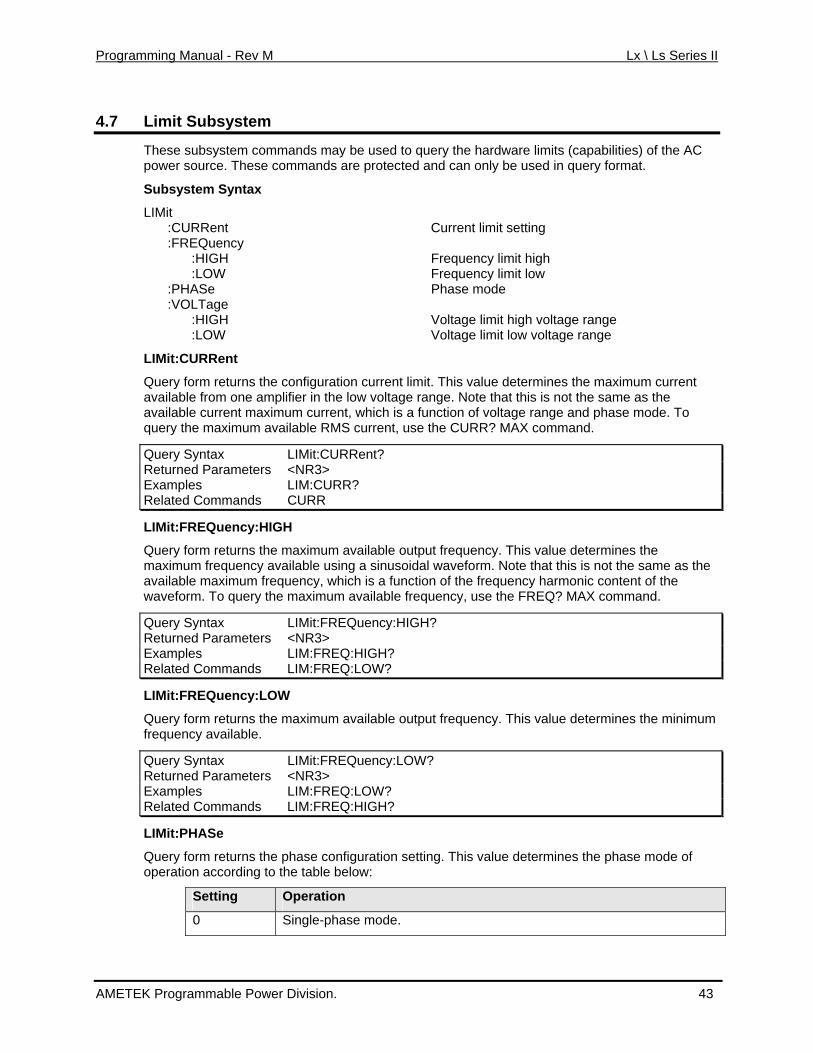
Programming Manual - Rev M Lx \ Ls Series II
4.7 Limit Subsystem
These subsystem commands may be used to query the hardware limits (capabilities) of the AC power s hese c
Subsystem Syntax
IMit Current limit setting
cy limit high
quency limit low Phase mode
Voltage limit high voltage range
current
nction of voltage range and phase mode. To R? MAX command.
ource. T ommands are protected and can only be used in query format.
L :CURRent :FREQuen :HIGH Frequency :LOW Fre :PHASe :VOLTage :HIGH :LOW Voltage limit low voltage range
LIMit:CURRent
Query form returns the configuration current limit. This value determines the maximumavailable from one amplifier in the low voltage range. Note that this is not the same as the available current maximum current, which is a fuquery the maximum av ilable RMa S current, use the CUR
Query Syntax LIMit:CURRent? Returned Parameters <NR3> Examples LIM:CURR? Related Commands CURR
LIMit:FREQuency:HIGH
Query form returns the maximum available output frequency. This value determines the rm. Note that this is not the same as the
n of the frequency harmonic content of the
IGH?
maximum frequency available using a sinusoidal wavefoavailable maximum frequency, which is a functiowaveform. To query the maximum available frequency, use the FREQ? MAX command.
Query Syntax LIMit:FREQuency:HReturned Parameters <NR3> Examples LIM:FREQ:HIGH? Related Commands LIM:FREQ:LOW?
LIMit:FREQuency:LOW
Query form returns the maximum available output frequency. This value determines the minimum frequency available.
Query Syntax LIMit:FREQuency:LOW? Returned Parameters <NR3> Examples LIM:FREQ:LOW? Related Commands LIM:FREQ:HIGH?
LIMit:PHASe
Query form returns the phase configuration setting. This value determines the phase mode of operation according to the table below:
Setting Operation
0 Single-phase mode.
AMETEK Programmable Power Division. 43
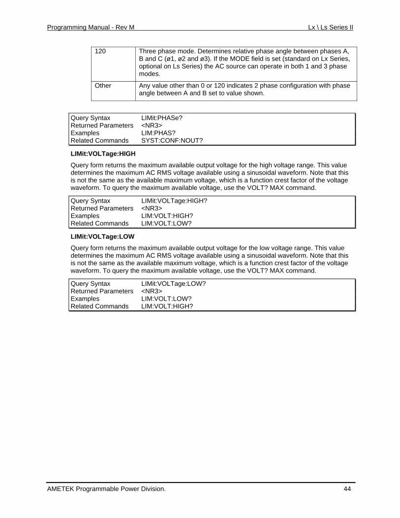
Programming Manual - Rev M Lx \ Ls Series II
120 Three phase mode. Determines relative phase angle between phases A, d ø3). If the MODE field is set (standard on Lx Series, B and C (ø1, ø2 an
optional on Ls Series) the AC source can operate in both 1 and 3 phase modes.
Other Any value other than 0 or 120 indicates 2 phase configuration with phangle between A and B set to value shown.
ase
Query Syntax LIMit:PHASe? Returned Parameters <NR3> Examples LIM:PHAS? Related Commands SYST:CONF:NOUT?
LIMit:VOLTage:HIGH
maximum available output voltage for the high voltage range. This value te that this
vailable maximum voltage, which is a function crest factor of the voltage
LIMit:VOLTage:
Query form returns the determines the maximum AC RMS voltage available using a sinusoidal waveform. Nois not the same as the awaveform. To query the maximum available voltage, use the VOLT? MAX command.
Query Syntax HIGH? Returned Parameters <NR3> Examples LIM:VOLT:HIGH? Related Commands ? LIM:VOLT:LOW
LIMit:VOLTage:LOW
Query form returns the maximum available output voltage for the low voltage range. This value m AC RMS voltage available using a sinusoidal waveform. Note that this
he voltage imum available voltage, use the VOLT? MAX command.
determines the maximuis not the same as the available maximum voltage, which is a function crest factor of twaveform. To query the max
Q r y x LIMit:VOLTage:LOW? ue y S nta Returned Parameters <NR3> Examples LIM:VOLT:LOW? Related Commands LIM:VOLT:HIGH?
AMETEK Programmable Power Division. 44
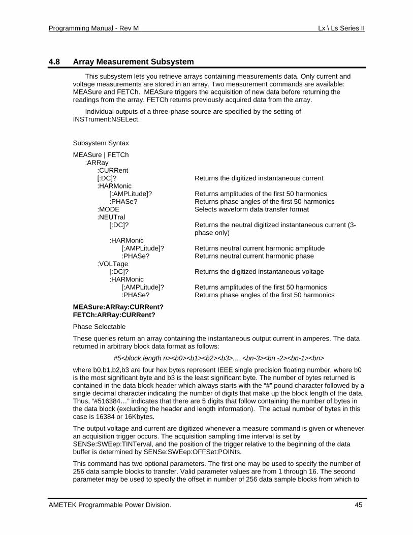
Programming Manual - Rev M Lx \ Ls Series II
4.8 Array Measurement Subsystem
This subsystem lets you retrieve arrays containing measurements data. Only current anvoltage measurements are stored in an array. Two measurement commands are available:
d
readings from the array.
Individual outputs of are specified by the setting of
Subsystem Syntax
Returns the neutral digitized instantaneous current (3-
turns neutral current harmonic amplitude
Returns the digitized instantaneous voltage :HARMonic
plitudes of the first 50 harmonics phase angles of the first 50 harmonics
CURRent?
ata
ion floating number, where b0 es returned is
ber of digits that make up the block length of the data. e number of bytes in
bytes in this
d gitized whenever a measure command is given or whenever tion sampling time interval is set by ion of the trigger relative to the beginning of the data
MEASure and FETCh. MEASure triggers the acquisition of new data before returning the FETCh returns previously acquired data from the array.
a three-phase source INSTrument:NSELect.
MEASure | FETCh :ARRay :CURRent [:DC]? Returns the digitized instantaneous current :HARMonic [:AMPLitude]? Returns amplitudes of the first 50 harmonics :PHASe? Returns phase angles of the first 50 harmonics :MODE Selects waveform data transfer format :NEUTral [:DC]?
phase only) :HARMonic [:AMPLitude]? Re :PHASe? Returns neutral current harmonic phase :VOLTage [:DC]?
[:AMPLitude]? Returns am :PHASe? Returns
MEASure:ARRay:FETCh:ARRay:CURRent?
Phase Selectable
These queries return an array containing the instantaneous output current in amperes. The dreturned in arbitrary block data format as follows:
#5<block length n><b0><b1><b2><b3>.....<bn-3><bn -2><bn-1><bn>
where b0,b1,b2,b3 are four hex bytes represent IEEE single precisis the most significant byte and b3 is the least significant byte. The number of bytcontained in the data block header which always starts with the “#” pound character followed by a single decimal character indicating the numThus, “#516384…” indicates that there are 5 digits that follow containing ththe data block (excluding the header and length information). The actual number ofcase is 16384 or 16Kbytes.
The output voltage an current are dian acquisition trigger occurs. The acquisiSENSe:SWEep:TINTerval, and the positbuffer is determined by SENSe:SWEep:OFFSet:POINts.
This command has two optional parameters. The first one may be used to specify the number of 256 data sample blocks to transfer. Valid parameter values are from 1 through 16. The second parameter may be used to specify the offset in number of 256 data sample blocks from which to
AMETEK Programmable Power Division. 45
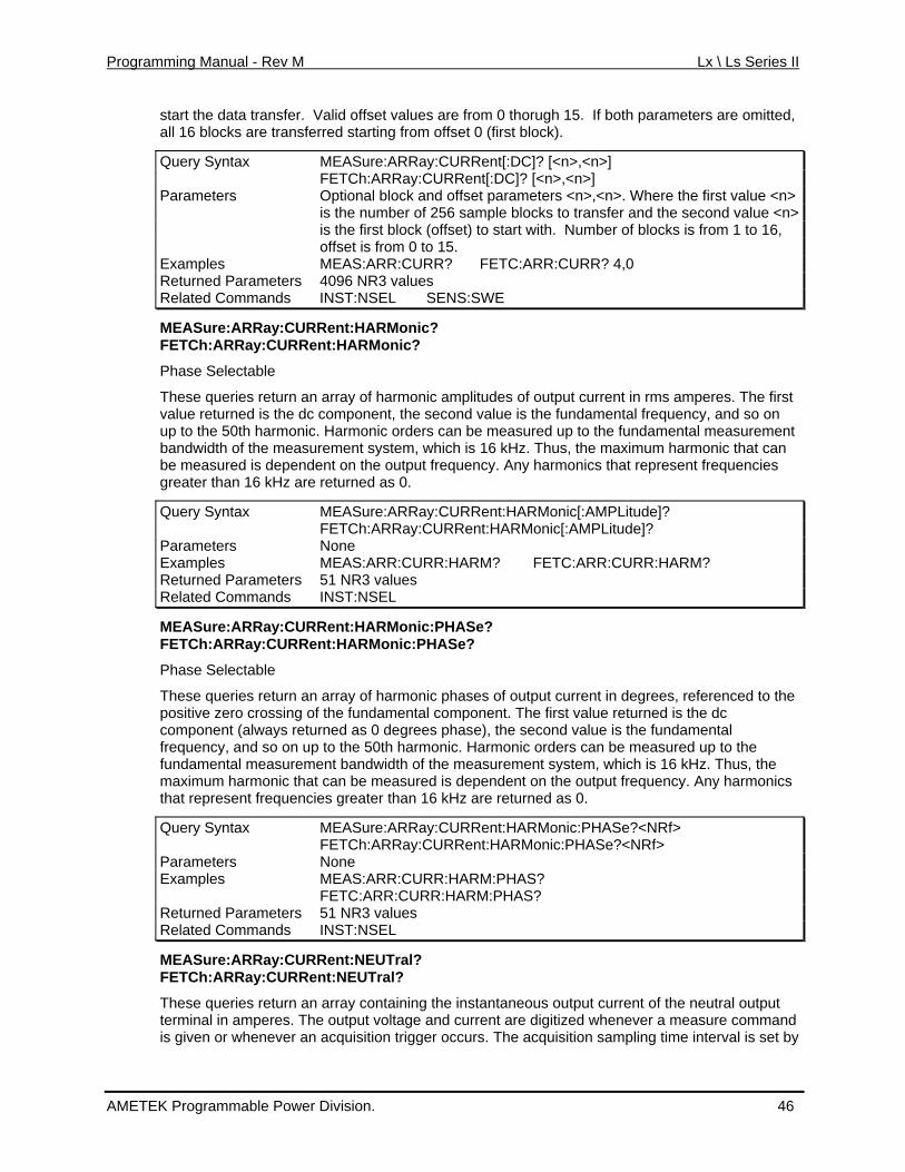
Programming Manual - Rev M Lx \ Ls Series II
start the data transfer. Valid offset values are from 0 thorugh 15. If both parameters are omittall 16 blocks are transferred starting from offset 0 (first blo
ed, ck).
Query Syntax MEASure:ARRay:CURRent[:DC]? [<n>,<n>] FETCh:ARRay:CURRent[:DC]? [<n>,<n>] Parameters Optional block and offset parameters <n>,<n>. Where the first value <n>
is the number of 256 sample blocks to transfer and the second value <n> is the first block (offset) to start with. Number of blocks is from 1 to 16, offset is from 0 to 15.
Examples MEAS:ARR:CURR? FETC:ARR:CURR? 4,0 Returned Parameters 4096 NR3 values Related Commands INST:NSEL SENS:SWE
MEASure:ARRay:CURRent:HARMonic? FETCh:ARRay:CURRent:HARMonic?
first on
to the fundamental measurement
ncies
de]?
Phase Selectable
These queries return an array of harmonic amplitudes of output current in rms amperes. The value returned is the dc component, the second value is the fundamental frequency, and so up to the 50th harmonic. Harmonic orders can be measured upbandwidth of the measurement system, which is 16 kHz. Thus, the maximum harmonic that can be measured is dependent on the output frequency. Any harmonics that represent frequegreater than 16 kHz are returned as 0.
Query Syntax MEASure:ARRay:CURRent:HARMonic[:AMPLitu FETCh:ARRay:CURRent:HARMonic[:AMPLitude]? Parameters None Examples MEAS:ARR:CURR:HARM? FETC:ARR:CURR:HARM? Returned Parameters 51 NR3 values Related Commands INST:NSEL
MEASure:ARRay:CURRent:HARMonic:PHASe? FETCh:ARRay:CURRent:HARMonic:PHASe?
Phase Selectable
These queries return an array of harmonic phases of output current in degrees, referenced to the positive zero crossing of the fundamental component. The first value returned is the dc component (always returned as 0 degrees phase), the second value is the fundamental frequency, and so on up to the 50th harmonic. Harmonic orders can be measured up to the fundamental measurement bandwidth of the measurement system, which is 16 kHz. Thus, the
kHz are returned as 0. maximum harmonic that can be measured is dependent on the output frequency. Any harmonics that represent frequencies greater than 16
Query Syntax MEASure:ARRay:CURRent:HARMonic:PHASe?<NRf> FETCh:ARRay:CURRent:HARMonic:PHASe?<NRf> Parameters None Examples MEAS:ARR:CURR:HARM:PHAS? FETC:ARR:CURR:HARM:PHAS? Returned Parameters 51 NR3 values Related Commands INST:NSEL
MEASure:ARRay:CURRent:NEUTral? FETCh:ARRay:CURRent:NEUTral?
These queries return an array containing the instantaneous output current of the neutral output terminal in amperes. The output voltage and current are digitized whenever a measure commis given or whenever an acquisition trigger o
and ccurs. The acquisition sampling time interval is set by
AMETEK Programmable Power Division. 46
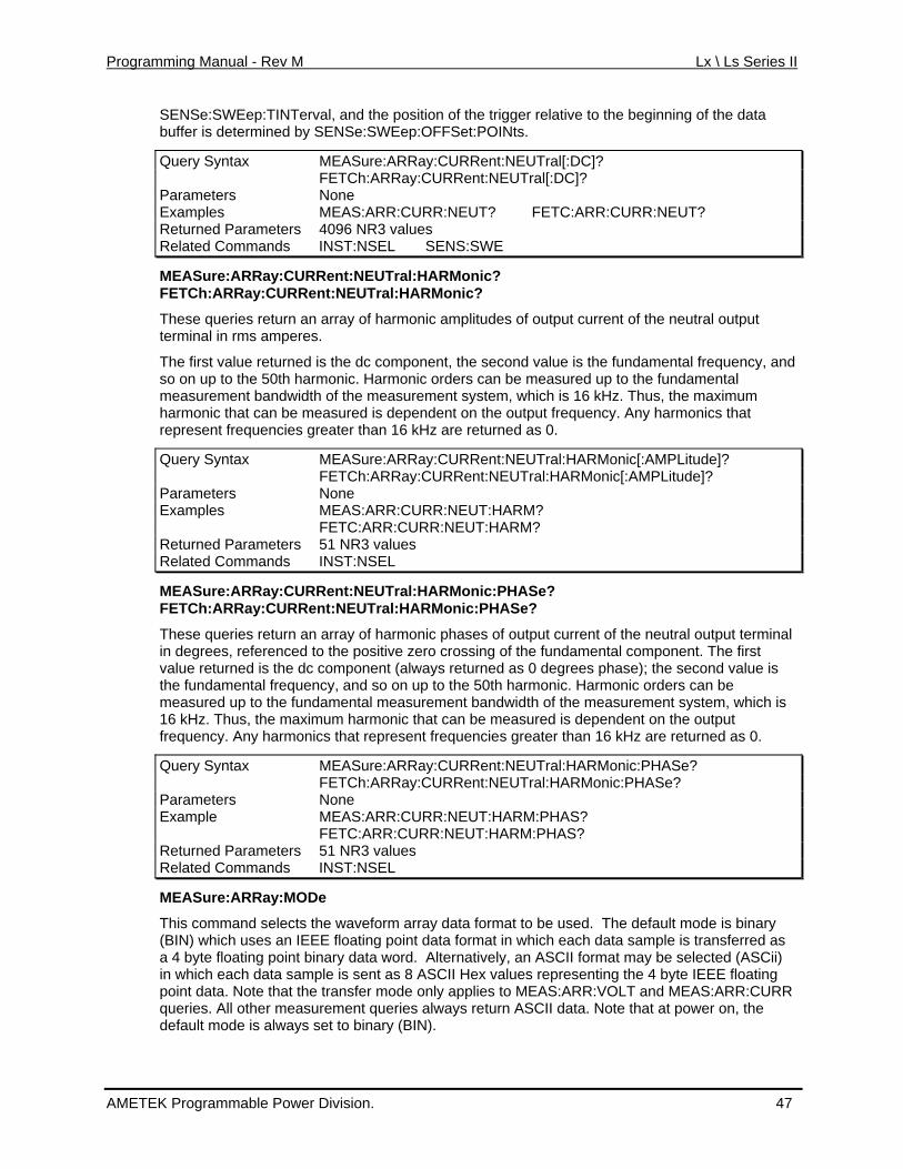
Programming Manual - Rev M Lx \ Ls Series II
SENSe:SWEep:TINTerval, and the position of the trigger relative to the beginning of the data p: ts. buffer is determined by SENSe:SWEe OFFSet:POIN
Query Syntax MEASure:ARRay:CURRent:NEUTral[:DC]? FETCh:ARRay:CUR t:NEUTral[:DC]? RenParameters None Examples MEAS:ARR:CURR:NEUT? FETC:ARR:CURR:NEUT? Returned Parameters 4096 NR3 values Related Commands INST:NSEL SENS:SWE
MEASure:ARRay:CURRent:NEUTral:HARMonic?
c. Harmonic orders can be measured up to the fundamental
y harmonics that
onic[:AMPLitude]?
FETCh:ARRay:CURRent:NEUTral:HARMonic?
These queries return an array of harmonic amplitudes of output current of the neutral output terminal in rms amperes.
The first value returned is the dc component, the second value is the fundamental frequency, and so on up to the 50th harmonimeasurement bandwidth of the measurement system, which is 16 kHz. Thus, the maximum harmonic that can be measured is dependent on the output frequency. Anrepresent frequencies greater than 16 kHz are returned as 0.
Query Syntax MEASure:ARRay:CURRent:NEUTral:HARM FETCh:ARRay:CURRent:NEUTral:HARMonic[:AMPLitude]? Parameters None Examples MEAS:ARR:CURR:NEUT:HARM? FETC:ARR:CURR:NEUT:HARM? Returned Parameters 51 NR3 values Related Commands INST:NSEL
MEASure:ARRay:CURRent:ENEUTral:HARMonic:PHASe? UTral:HARMonic:PHASe?
e neutral output terminal
ase); the second value is nd so on up to the 50th harmonic. Harmonic orders can be
surement system, which is monic that can be measured is dependent on the output epresent frequencies greater than 16 kHz are returned as 0.
FETCh:ARRay:CURRent:N
These queries return an array of harmonic phases of output currositive zero crossing of the fundamental component. The first
ent of thin degrees, referenced to the pvalue returned is the dc com
aponent (always returned as 0 degrees ph
the fundamental frequency,measured up to the fundamental measurement bandwidth of the mea16 kHz. Thus, the maximum har
ics that rfrequency. Any harmon
Query Syntax MEASure:ARRay:CURRent:NEUTral:HARMonic:PHASe? FETCh:ARRay:CURRent:NEUTral:HARMonic:PHASe? Parameters None Example MEAS:ARR:CURR:NEUT:HARM:PHAS? FETC:ARR:CURR:NEUT:HARM:PHAS? Returned Parameters 51 NR3 values Related Commands INST:NSEL
MEASure:ARRay:MODe
This command selects the waveform array data format IEEE floating point data format in w
to be used. The default mode is binary hich each data sample is transferred as
rnatively, an ASCII format may be selected (ASCii) h data sample is sent as 8 ASCII Hex values representing the 4 byte IEEE floating
at the transfer mode only applies to MEAS:ARR:VOLT and MEAS:ARR:CURR always return ASCII data. Note that at power on, the N).
(BIN) which uses an a 4 byte floating point binary data word. Altein which eacpoint data. Note thqueries. All other measurement queries
nary (BIdefault mode is always set to bi
AMETEK Programmable Power Division. 47
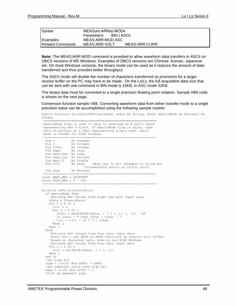
Programming Manual - Rev M Lx \ Ls Series II
Syntax MEASure:ARRay:MODe Parameters BIN | ASCii Examples MEAS:ARR:MOD ASC Related Commands MEAS:ARR:VOLT MEAS:ARR:CURR
Note: The MEAS:ARR:MOD command is provided to allow waveform data transfers in ASCII on rsions are Chinese, Korean, Japanese e used as it reduces the amount of data
better throughput.
r of characters transferred so provisions for a larger e made. On the Lx/Ls, the full acquisition data size that mode is 16KB, in ASC mode 32KB.
a must be converted to a single precision floating point notation. Sample VB6 code
onverting waveform data from either transfer mode to a single shed using the following sample routine:
AsciiMode As Boolean) As
================== as 8 ascii chars
. If bAsciiMode flag is false, then as 4 char representing a byte each. Ascii
d for DCBS windows ================================================
Dim i As Integer Dim j As Integer
Variant Single
Const MANT_MConst EXPO_MAX = 2 ^ 126
Data, i * 2 + j + 1, 1)) - 48
expo = (c(0) And &H7F) * 2 'Pick up exponent sign
DBCS versions of MS Windows. Examples of DBCS veetc. On most Windows versions, the binary mode can btransferred and thus provides
The ASCII mode will double the number on the PC may have to breceive buffe
can be sent with one command in BIN
The binary datis shown on the next page.
Conversion function sample VBcan be accompli
6. Cprecision value Public Function StringToIEEEFloat(ByVal sData As String, ByVal bSingle '===========================================
if data is received'bAsciiMode flag is usedx 0-9,A-F'representing He
data is process ''mode is neede
============'=
Dim iChar As Integer Dim expo As Long Dim mantisse As Long Dim expo_val As Dim mant_f As Dim c(3) As Long 'Must use 32 bit integers to allow for 'intermediate result of 24 bit shift Dim sign As Boolean '=============================================================
AX = &H7FFFFF
'============================================================= On Error GoTo FloatConvError If bAsciiMode Then 'Retrieve ASC values from eight hex byte input data sData = UCase(sData) For i = 0 To 3 c(i) = 0 For j = 0 To 1 iChar = AscB(Mid$(s If iChar > 9 Then iChar = iChar - 7 c(i) = c(i) * 16 * j + iChar Next j Next i Else 'Retrieve ASC values from four byte input data 'Note: Don't use ASCB or ASCW functions as results will differ 'based on character sets, even on non DCBS Windows 'Retrieve ASC values from four byte input data For i = 0 To 3 c(i) = Asc(Mid$(sData, i + 1, 1)) Next i End If 'Get sign bit sign = ((c(0) And &H80) = &H80) 'Get exponent value less sign bit
AMETEK Programmable Power Division. 48
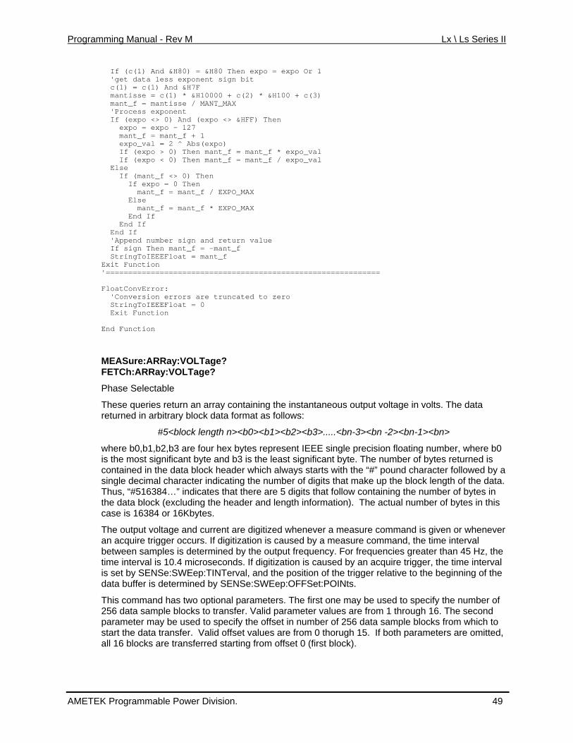
Programming Manual - Rev M Lx \ Ls Series II
If (c(1) And &H80) = &H80 Then expo = expo Or 1 'get data less exponent sign bit c(1) = c(1) And &H7F mantisse = c(1) * &H10000 + c(2) * &H100 + c(3) mant_f = m MANT_MAX
expo <> &HFF) Then
antisse / 'Process exponent If (expo <> 0) And ( expo = expo - 127
n al en t_
ant_f * EXPO_MAX
MEASure:ARRay:VOLTage? FETCh:ARRay:VOLTage?
Phase Selectable
These queries return an array containing the instantaneous output voltage in volts. The data returned in arbitrary block data format as follows:
#5<block length n><b0><b1><b2><b3>.....<bn-3><bn -2><bn-1><bn>
where b0,b1,b2,b3 are four hex bytes represent IEEE single precision floating number, where b0 is the most significant byte and b3 is the least significant byte. The number of bytes returned is contained in the data block header which always starts with the “#” pound character followed by a single decimal character indicating the number of digits that make up the block length of the data. Thus, “#516384…” indicates that there are 5 digits that follow containing the number of bytes in the data block (excluding the header and length information). The actual number of bytes in this case is 16384 or 16Kbytes.
The output voltage and current are digitized whenever a measure command is given or whenever an acquire trigger occurs. If digitization is caused by a measure command, the time interval between samples is determined by the output frequency. For frequencies greater than 45 Hz, the time interval is 10.4 microseconds. If digitization is caused by an acquire trigger, the time interval is set by SENSe:SWEep:TINTerval, and the position of the trigger relative to the beginning of the data buffer is determined by SENSe:SWEep:OFFSet:POINts.
This command has two optional parameters. The first one may be used to specify the number of 256 data sample blocks to transfer. Valid parameter values are from 1 through 16. The second parameter may be used to specify the offset in number of 256 data sample blocks from which to start the data transfer. Valid offset values are from 0 thorugh 15. If both parameters are omitted, all 16 blocks are transferred starting from offset 0 (first block).
mant_f = mant_f + 1 expo_val = 2 ^ Abs(expo) If (expo > 0) The mant_f = mant_f * expo_v If (expo < 0) Th mant_f = man f / expo_val Else If (mant_f <> 0) Then If expo = 0 Then mant_f = mant_f / EXPO_MAX Else mant_f = m End If End If End If 'Append number sign and return value If sign Then mant_f = -mant_f StringToIEEEFloat = mant_f Exit Function '============================================================= FloatConvError: 'Conversion errors are truncated to zero StringToIEEEFloat = 0 Exit Function End Function
AMETEK Programmable Power Division. 49
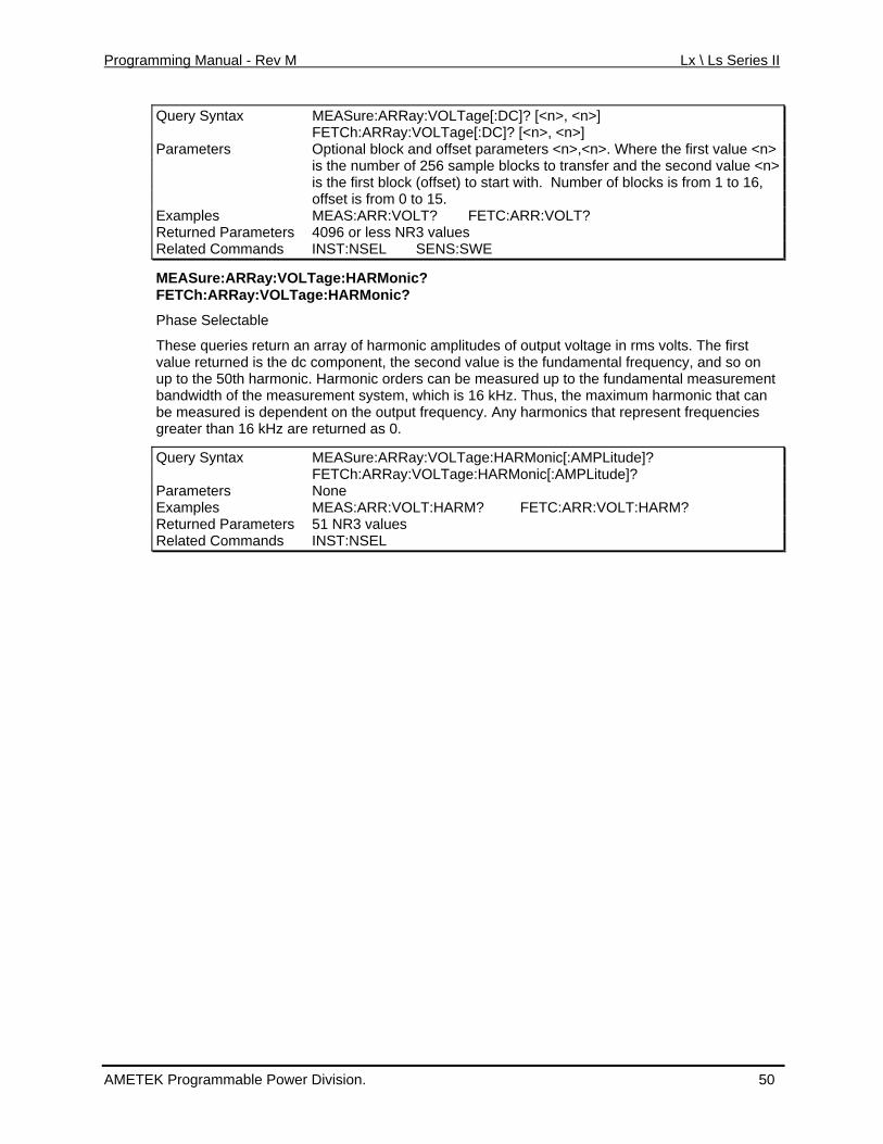
Programming Manual - Rev M Lx \ Ls Series II
Query Syntax MEASure:ARRay:VOLTage[:DC]? [<n>, <n>] FETCh:ARRay:VOLTage[:DC]? [<n>, <n>] Parameters Optional block and offset parameters <n>,<n>. Where the first value <n>
is the number of 256 sample blocks to transfer and the second value <n> is the first block (offset) to start with. Number of blocks is from 1 to 16, offset is from 0 to 15.
Examples MEAS:ARR:VOLT? FETC:ARR:VOLT? Returned Parameters 4096 or less NR3 values Related Commands INST:NSEL SENS:SWE
MEASure:ARRay:VOLTage:HARMonic?
n an array of harmonency, and so on
ndamental measurement mum harmonic that can
n the outputrned as 0.
ude]?
FETCh:ARRay:VOLTage:HARMonic?
Phase Selectable
These queries retur ic amplitudes of output voltage in rms volts. The first value returned is the dc component, the second value is the fundamental frequup to the 50th harmonic. Harmonic orders can be measured up to the fubandwidth of the measurement system, which is 16 kHz. Thus, the maxibe measured is dependent o frequency. Any harmonics that represent frequencies greater than 16 kHz are retu
Query Syntax MEASure:ARRay:VOLTage:HARMonic[:AMPLit FETCh:ARRay:VOLTage:HARMonic[:AMPLitude]? Parameters None Examples MEAS:ARR:VOLT:HARM? FETC:ARR:VOLT:HARM? Returned Parameters 51 NR3 values Related Commands INST:NSEL
AMETEK Programmable Power Division. 50
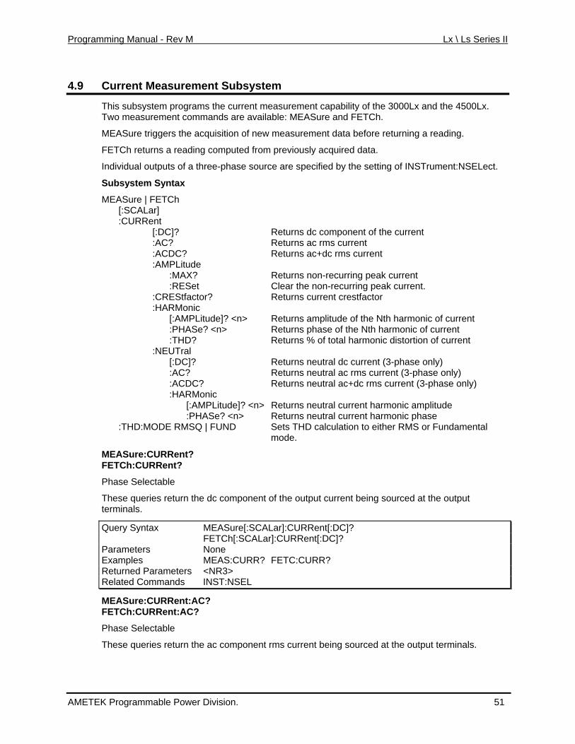
Programming Manual - Rev M Lx \ Ls Series II
4.9 Current Measurement Subsystem
This subsystem programs the current measurement capability of the 3000Lx and the 4500Lx. m e available: MEASure and FETCh.
a ew measurement data before returning a reading.
uted from previously acquired data.
pecified by the setting of INSTrument:NSELect.
turns ac rms current
Returns non-recurring peak current :RESet Clear the non-recurring peak current.
s current crestfactor
MPLitude]? <n> Returns amplitude of the Nth harmonic of current <n> Returns phase of the Nth harmonic of current
itude
of the output current being sourced at the output
Two measurement com ands ar
MEASure triggers the cquisition of n
FETCh returns a reading comp
Individual outputs of a three-phase source are s
Subsystem Syntax
MEASure | FETCh [:SCALar] :CURRent [:DC]? Returns dc component of the current :AC? Re :ACDC? Returns ac+dc rms current :AMPLitude :MAX?
:CREStfactor? Return :HARMonic [:A :PHASe? :THD? Returns % of total harmonic distortion of current :NEUTral [:DC]? Returns neutral dc current (3-phase only) :AC? Returns neutral ac rms current (3-phase only) :ACDC? Returns neutral ac+dc rms current (3-phase only)
:HARMonic [:AMPLitude]? <n> Returns neutral current harmonic ampl
:PHASe? <n> Returns neutral current harmonic phase ts THD calculation to either RMS or Fundamental :THD:MODE RMSQ | FUND Se
mode.
MEASure:CURRent? FETCh:CURRent?
Phase Selectable
These queries return the dc componentterminals.
Query Syntax MEASure[:SCALar]:CURRent[:DC]? FETCh[:SCALar]:CURRent[:DC]? Parameters None Examples MEAS:CURR? FETC:CURR? Returned Parameters <NR3> Related Commands INST:NSEL
MEASure:CURRent:AC? FETCh:CURRent:AC?
nent rms current being sourced at the output terminals.
Phase Selectable
These queries return the ac compo
AMETEK Programmable Power Division. 51
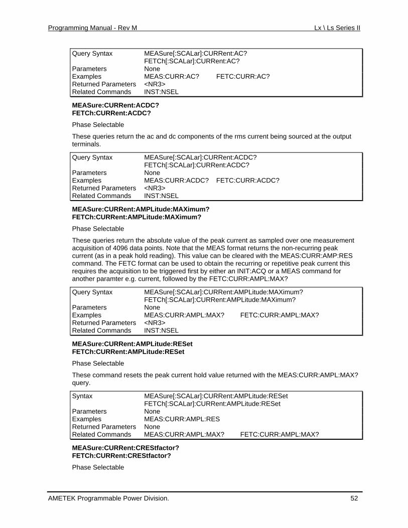
Programming Manual - Rev M Lx \ Ls Series II
Query Syntax MEASure[:SCALar]:CURRent:AC? FETCh[:SCALar]:CURRent:AC? Parameters None Examples MEAS:CURR:AC? FETC:CURR:AC? Returned Parameters <NR3> Related Commands INST:NSEL
MEASure:CURRent:ACDC? FETCh:CURRent:ACDC?
Phase Selectable
These queries return the ac and dc components of the rms current being sourced at the output terminals.
Query Syntax MEASure[:SCALar]:CURRent:ACDC? FETCh[:SCALar]:CURRent:ACDC? Parameters None Examples MEAS:CURR:ACDC? FETC:CURR:ACDC? Returned Parameters <NR3> Related Commands INST:NSEL
MEASure:CURRent:AMPLitude:MAXimum? FETCh:CURRent:AMPLitude:MAXimum?
Phase Selectable
These queries return the absolute value of the peak current as sampled over one measurement a that the MEAS format returns the non-recurring peak
ho his value can be cleared with the MEAS:CURR:AMP:RES obtain the recurring or repetitive peak current this y either an INIT:ACQ or a MEAS command for
the FETC:CURR:AMPL:MAX?
acquisition of 4096 dat points. Note current (as in a peak ld reading). Tcommand. The FETC format can be used torequires the acquisition to be triggered first banother paramter e.g. current, followed by
Query Syntax MEASure[:SCALar]:CURRent:AMPLitude:MAXimum? FETCh[:SCALar]:CURRent:AMPLitude:MAXimum? Parameters None Examples MEAS:CURR:AMPL:MAX? FETC:CURR:AMPL:MAX? Returned Parameters <NR3> Related Commands INST:NSEL
MEASure:CURRent:AMPLitude:RESet FETCh:CURRent:AMPLitude:RESet
Phase Selectable
These comm the peakand resets current hold value retu ned with the MEAS:CURR:AMPquery.
r L:MAX?
ALar]:CURRent:AMPLitude:RESet Syntax MEASure[:SC FETCh[:SCALar]:CURRent:AMPLitude:RESet Parameters None Examples MEAS:CURR:AMPL:RES Returned Parameters None Related Commands MEAS:CURR:AMPL:MAX? FETC:CURR:AMPL:MAX?
MEASure:CURRent:CREStfactor? FETCh:CURRent:CREStfactor?
Phase Selectable
AMETEK Programmable Power Division. 52
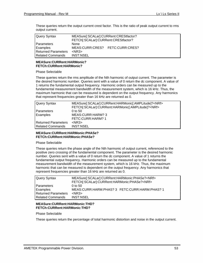
Programming Manual - Rev M Lx \ Ls Series II
These queries return the output current crest factor. This is the ratio of peak output current to rms output current.
Query Syntax MEASure[:SCALar]:CURRent:CREStfactor? FETCh[:SCALar]:CURRent:CREStfactor? Parameters None Examples MEAS:CURR:CRES? FETC:CURR:CRES? Returned Parameters <NR3> Related Commands INST:NSEL
MEASure:CURRent:HARMonic? FETCh:CURRent:HARMonic?
Phase Selectable
These queries return the rms amplitude of the Nth harmonic of output current. The parameter is the desired harmonic number. Queries sent with a value of 0 return the dc component. A value of
t uency. Harmonic orders can be measured up to the m of the measurement system, which is 16 kHz. Thus, the
ured is dependent on the output frequency. Any harmonics n 16 kHz are returned as 0.
1 returns the fundamen al output freqfundamental measure ent bandwidthmaximum harmonic that can be measthat represent frequencies greater tha
Query Syntax MEASure[:SCALar]:CURRent:HARMonic[:AMPLitude]?<NRf> FETCh[:SCALar]:CURRent:HARMonic[:AMPLitude]?<NRf> Parameters 0 to 50 Examples MEAS:CURR:HARM? 3 FETC:CURR:HARM? 1 Returned Parameters <NR3> Related Commands INST:NSEL
MEASure:CURRent: RMonic:PHAHA Se? FETCh:CURRent:HARMonic:PHASe?
Queries sent with a value of 0 return the dc component. A value of 1 returns the he fundamental
ALar]:CURRent:HARMonic:PHASe?<NRf>
Phase Selectable
These queries return the phase angle of the Nth harmonic of output current, referenced to the positive zero crossing of the fundamental component. The parameter is the desired harmonic number. fundamental output frequency. Harmonic orders can be measured up to tmeasurement bandwidth of the measurement system, which is 16 kHz. Thus, the maximum
nt on the output frequency. Any harmonics that harmonic that can be measured is dependerepresent frequencies greater than 16 kHz are returned as 0.
Query Syntax MEASure[:SC FETCh[:SCALar]:CURRent:HARMonic:PHASe?<NRf> Parameters 0 to 50 Examples MEAS:CURR:HARM:PHAS? 3 FETC:CURR:HARM:PHAS? 1 Returned Parameters <NR3> Related Commands INST:NSEL
MEASure:CURRent:HARMonic:THD? FETCh:CURRent:HARMonic:THD?
Phase Selectable
These queries return the percentage of total harmonic distortion and noise in the output current.
AMETEK Programmable Power Division. 53
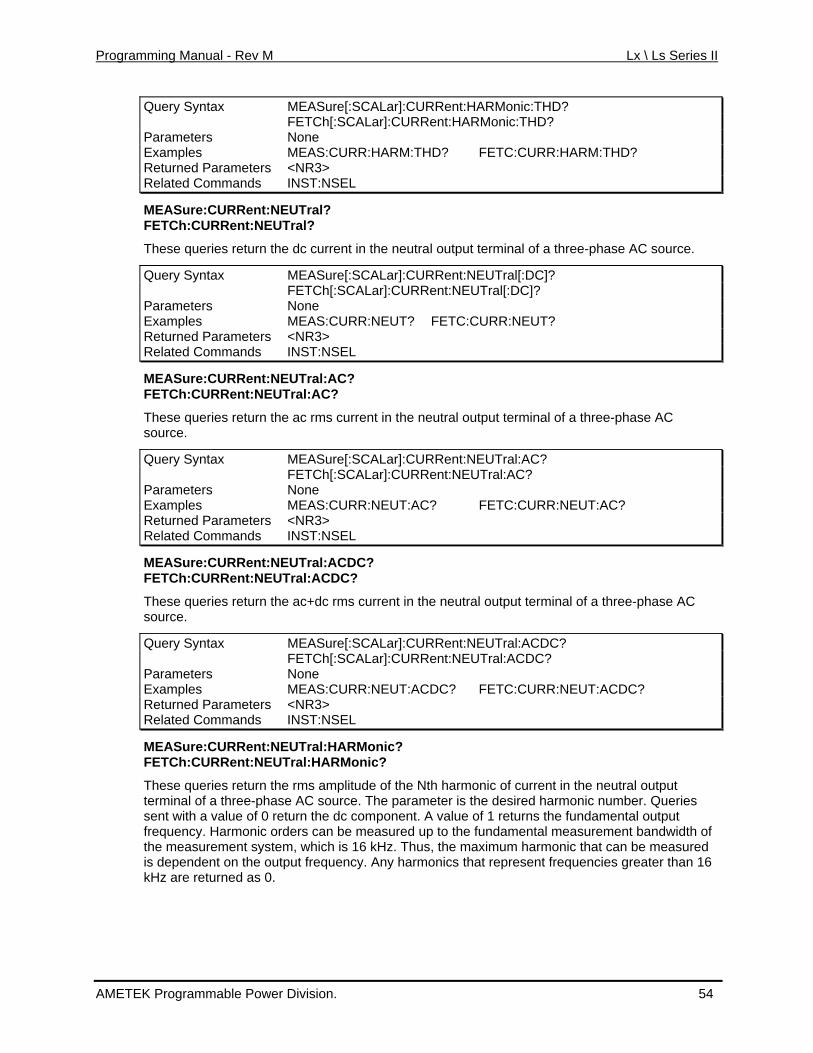
Programming Manual - Rev M Lx \ Ls Series II
Query Syntax MEASure[:SCALar]:CURRent:HARMonic:THD? FETCh[:SCALar]:CURRent:HARMonic:THD? Parameters None Examples MEAS:CURR:HARM:THD? FETC:CURR:HARM:THD? Returned Pa <NR3> rameters Related Commands INST:NSEL
MEASure:CURRent:NEUTral? FETCh:CURRent:NEUTral?
These queries return the dc current in the neutral output terminal of a three-phase AC source.
Query Syntax MEASure[:SCALar]:CURRent:NEUTral[:DC]? FETCh[:SCALar]:CURRent:NEUTral[:DC]? Parameters None Examples MEAS:CURR:NEUT? FETC:CURR:NEUT? Returned Parameters <NR3> Related Commands INST:NSEL
MEASure:CURRent:NEUTral:AC? FETCh:CURRent:NEUTral:AC?
These queries return the ac rms current in the neutral output terminal of a three-phase AC
C?
source.
Query Synta MEASux re[:SCALar]:CURRent:NEUTral:A FETCh[:SCALar]:CURRent:NEUTral:AC? Parameters None Examples MEAS:CURR:NEUT:AC? FETC:CURR:NEUT:AC? Returned Parameters <NR3> Related Commands INST:NSEL
MEASure:CURRent:NEUTral:ACDC?
FETCh:CURRent:NEUTral:ACDC?
These queries return the ac+dc rms current in the neutral output terminal of a three-phase ACsource.
Query Syntax MEASure[:SCALar]:CURRent:NEUTral:ACDC? FETCh[:SCALar]:CURRent:NEUTral:ACDC? Parameters None Examples MEAS:CURR:NEUT:ACDC? FETC:CURR:NEUT:ACDC? Returned Parameters <NR3> Related Commands INST:NSEL
MEASure:CURRent:NEUTral:HARMonic? FETCh:CURRent:NEUTral:HARMonic?
These queries rms amplitude of thereturn tterminal of a three-pha e AC sou
he Nth harmonic of current in the neutral output s
ue o utput frequency. Harmonic orders can be measured up to the fundamental measurement bandwidth of the measurement system, which is 16 kHz. Thus, the maximum harmonic that can be measured is dependent on the output frequency. Any harmonics that represent frequencies greater than 16 kHz are returned as 0.
rce. The parameter is the desired harmonic number. Queries sent with a value of 0 return the dc component. A val f 1 returns the fundamental o
AMETEK Programmable Power Division. 54
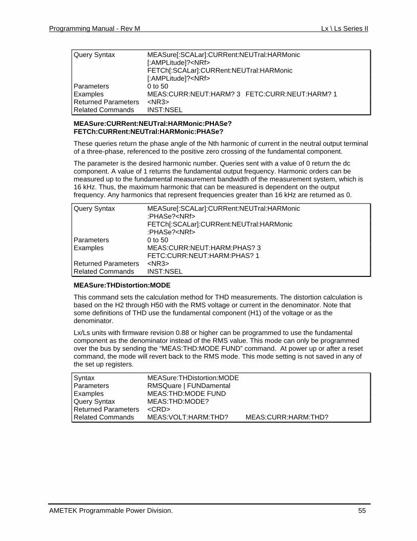
Programming Manual - Rev M Lx \ Ls Series II
Query Syntax MEASure[:SCALar]:CURRent:NEUTral:HARMonic [:AMPLitude]?<NRf> FETCh[:SCALar]:CURRent:NEUTral:HARMonic [:AMPLitude]?<NRf> Parameters 0 to 50 Examples MEAS:CURR:NEUT:HARM? 3 FETC:CURR:NEUT:HARM? 1 Returned Parameters <NR3> Related Commands INST:NSEL
MEASure:CURRent:NEUTral:HARMonic:PHASe? NEUTral:HARMonic:PHASe?
the neutral output terminal ed to the positive zero crossing of the fundamental component.
sired harmonic number. Queries sent with a value of 0 return the dc output frequency. Harmonic orders can be
measured up to the fundamental measurement bandwidth of the measurement system, which is d is dependent on the output
urned as 0.
onic
FETCh:CURRent:
These queries return the phase angle of the Nth harmonic of current in of a three-phase, referenc
The parameter is the decomponent. A value of 1 returns the fundamental
16 kHz. Thus, the maximum harmonic that can be measurefrequency. Any harmonics that represent frequencies greater than 16 kHz are ret
Query Syntax MEASure[:SCALar]:CURRent:NEUTral:HARM :PHASe?<NRf> FETCh[:SCALar]:CURRent:NEUTral:HARMonic :PHASe?<NRf> Parameters 0 to 50 Examples MEAS:CURR:NEUT:HARM:PHAS? 3 FETC:CURR:NEUT:HARM:PHAS? 1 Returned Parameters <NR3> Related Commands INST:NSEL
MEASure:THDistortion:MODE
This command sets the calculation method for THD measurements. The distortion calculation is based on the H2 through H50 with the RMS voltage or current in the denominator. Note that some definitions of THD use the fundamental component (H1) of the voltage or as the denominator.
Lx/Ls units with firmware revision 0.88 or higher can be programmed to use the fundamental component as the denominator instead of the RMS value. This mode can only be programmed over the bus by sending the “MEAS:THD:MODE FUND” command. At power up or after a reset command, the mode will revert back to the RMS mode. This mode setting is not saved in any of the set up registers.
Syntax MEASure:THDistortion:MODE Parameters RMSQuare | FUNDamental Examples MEAS:THD:MODE FUND Query Syntax MEAS:THD:MODE? Returned Parameters <CRD> Related Commands MEAS:VOLT:HARM:THD? MEAS:CURR:HARM:THD?
AMETEK Programmable Power Division. 55
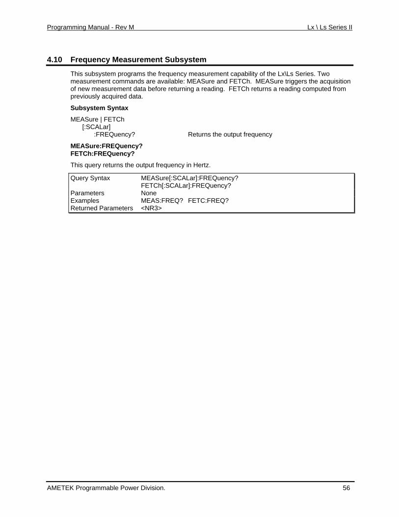
Programming Manual - Rev M Lx \ Ls Series II
4.10 Frequency Measurement Subsystem
This subsystem programs the frequency measurement capability of the Lx\Ls Series. Twmeasurement commands are available: MEASure and FETCh. MEASure triggers the acquisition of new measurement data before returning a reading. FETCh returns a reading computed from previously acquired data.
o
y? Returns the output frequency
cy? ET h: RE ?
e[:SCA
Subsystem Syntax
MEASure | FETCh [:SCALar]
c :FREQuen
MEASure:FREQuenF C F Quency
This query returns the output frequency in Hertz.
Query Syntax MEASur Lar]:FREQuency? FETCh[: r]:FREQuency? SCALaParameters None Examples MEAS:FREQ? FETC:FREQ? Returned Parameters <NR3>
AMETEK Programmable Power Division. 56
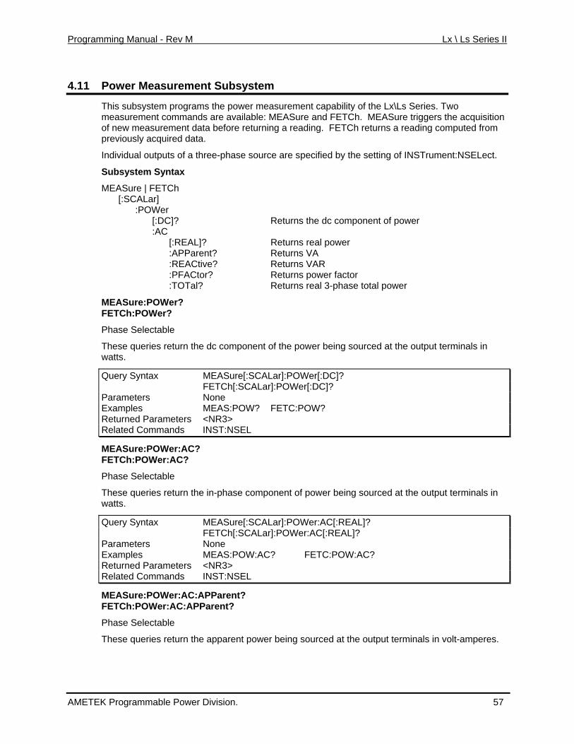
Programming Manual - Rev M Lx \ Ls Series II
4.11 Power Measurement Subsystem
This subsystem programs the power measurement capability of the Lx\Ls Series. Two d ilable: MEASure and FETCh. MEASure triggers the acquisition
da rning a reading. FETCh returns a reading computed from previously acquired data.
ource are specified by the setting of INSTrument:NSELect.
x
ponent of power C
Returns real 3-phase total power
er being sourced at the output terminals in
r]:POWer[:DC]?
measurement comman s are avaof new measurement ta before retu
Individual outputs of a three-phase s
Subsystem Synta
MEASure | FETCh [:SCALar] :POWer [:DC]? Returns the dc com :A [:REAL]? Returns real power :APParent? Returns VA :REACtive? Returns VAR :PFACtor? Returns power factor :TOTal?
MEASure:POWer? FETCh:POWer?
Phase Selectable
These queries return the dc component of the powwatts.
Query Syntax MEASure[:SCALa FETCh[:SCALar]:POWer[:DC]? Parameters None Examples MEAS:POW? FETC:POW? Returned Parameters <NR3> Related Commands INST:NSEL
MEASure:POWer:AC ?FETCh:POWer:AC?
Phase Selectable
These queries return the in-phase component of power being sourced at the output terminals in watts.
Query Syntax MEASure[:SCALar]:POWer:AC[:REAL]? FETCh[:SCALar]:POWer:AC[:REAL]? Parameters None Examples MEAS:POW:AC? FETC:POW:AC? Returned Parameters <NR3> Related Commands INST:NSEL
MEASure:POWer:AC:APParent? FETCh:POWer:AC:APParent?
Phase Selectable
These queries return the apparent power being sourced at the output terminals in volt-amperes.
AMETEK Programmable Power Division. 57
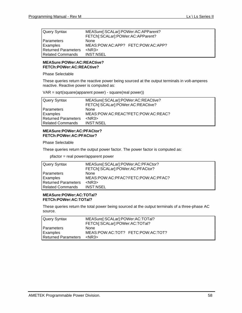
Programming Manual - Rev M Lx \ Ls Series II
Query Syntax MEASure[:SCALar]:POWer:AC:APParent? FETCh[:SCALar]:POWer:AC:APParent? Parameters None Examples MEAS:POW:AC:APP? FETC:POW:AC:APP? Returned Parameters <NR3> Related Commands INST:NSEL
MEASure:POWer:AC:REACtive? FETCh:POWer:AC:REACtive?
Phase Selectable
These queries return the reactive power being sourced at the output terminals in volt-amperes
L
reactive. Reactive power is computed as:
VAR = sqrt(square(apparent power) - square(real power))
Query Syntax MEASure[:SCA ar]:POWer:AC:REACtive? FETCh[:SCALar]:POWer:AC:REACtive? Parameters None Examples MEAS:POW:AC:REAC? FETC:POW:AC:REAC? Returned Parameters <NR3> Related Commands INST:NSEL
MEASure:POWer:AC:PFACtor? ACtor?
rn the output power factor. The power factor is computed as:
FETCh:POWer:AC:PF
Phase Selectable
These queries retu
pfactor = real power/apparent power
Query Syntax MEASure[:SCALar]:POWer:AC:PFACtor? FETCh[:SCALar]:POWer:AC:PFACtor? Parameters None Examples MEAS:POW:AC:PFAC? FETC:POW:AC:PFAC? Returned Parameters <NR3> Related Commands INST:NSEL
MEASure:POWer:AC:TOTal? FETCh:POWer:AC:TOTal?
ed at the output terminals of a three-phase AC These queries return the total power being sourcsource.
Query Syntax MEASure[:SCALar]:POWer:AC:TOTal? FETCh[:SCALar]:POWer:AC:TOTal? Parameters None Examples MEAS:POW:AC:TOT? FETC:POW:AC:TOT? Returned Parameters <NR3>
AMETEK Programmable Power Division. 58
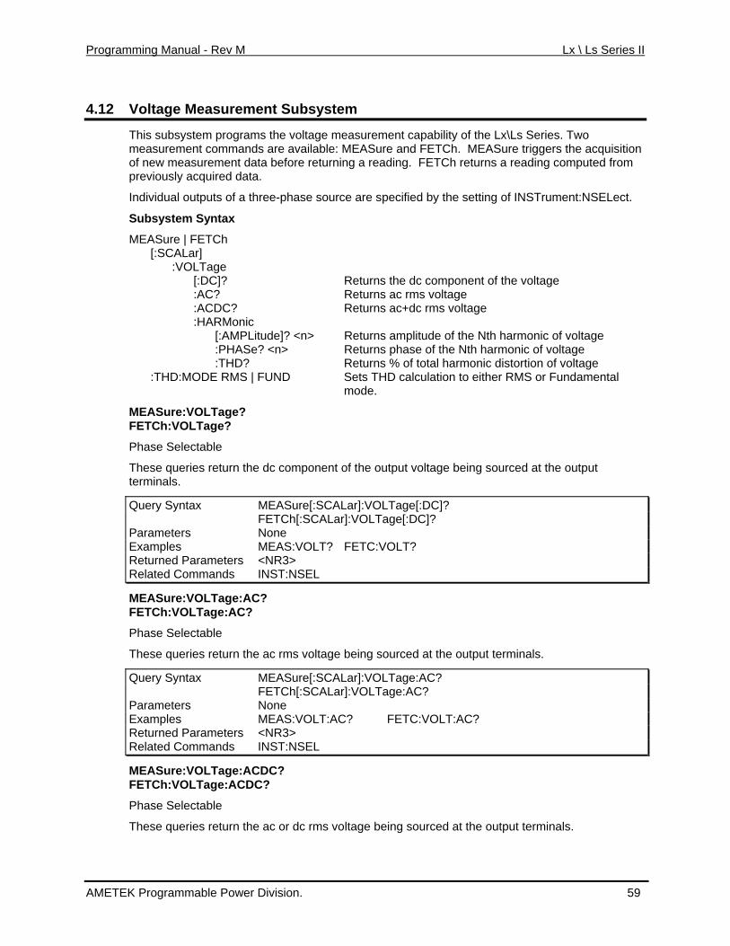
Programming Manual - Rev M Lx \ Ls Series II
4.12 Voltage Measurement Subsystem
This subsystem programs the voltage measurement capability of the Lx\Ls Series. Two d ilable: MEASure and FETCh. MEASure triggers the acquisition
da rning a reading. FETCh returns a reading computed from previously acquired data.
source are specified by the setting of INSTrument:NSELect.
x
e e
:THD? Returns % of total harmonic distortion of voltage o either RMS or Fundamental
he output voltage being sourced at the output
measurement comman s are avaof new measurement ta before retu
Individual outputs of a three-phase
Subsystem Synta
MEASure | FETCh [:SCALar] :VOLTage [:DC]? Returns the dc component of the voltage :AC? Returns ac rms voltage :ACDC? Returns ac+dc rms voltage :HARMonic [:AMPLitude]? <n> Returns amplitude of the Nth harmonic of voltag :PHASe? <n> Returns phase of the Nth harmonic of voltag :THD:MODE RMS | FUND Sets THD calculation t
mode.
MEASure:VOLTageFETCh:VOLTage?
?
Phase Selectable
These queries return the dc component of tterminals.
Query Syntax MEASure[:SCALar]:VOLTage[:DC]? FETCh[:SCALar]:VOLTage[:DC]? Parameters None Examples MEAS:VOLT? FETC:VOLT? Returned Parameters <NR3> Related Commands INST:NSEL
MEASure:VOLTage:AC? FETCh:VOLTage:AC?
Phase Selectable
CALar]:VOLTage:AC?
These queries return the ac rms voltage being sourced at the output terminals.
Query Syntax MEASure[:S FETCh[:SCALar]:VOLTage:AC? Parameters None Examples MEAS:VOLT:AC? FETC:VOLT:AC? Returned Parameters <NR3> Related Commands INST:NSEL
MEASure:VOLTage:ACDC? FETCh:VOLTage:ACDC?
Phase Selectable
These queries return the ac or dc rms voltage being sourced at the output terminals.
AMETEK Programmable Power Division. 59
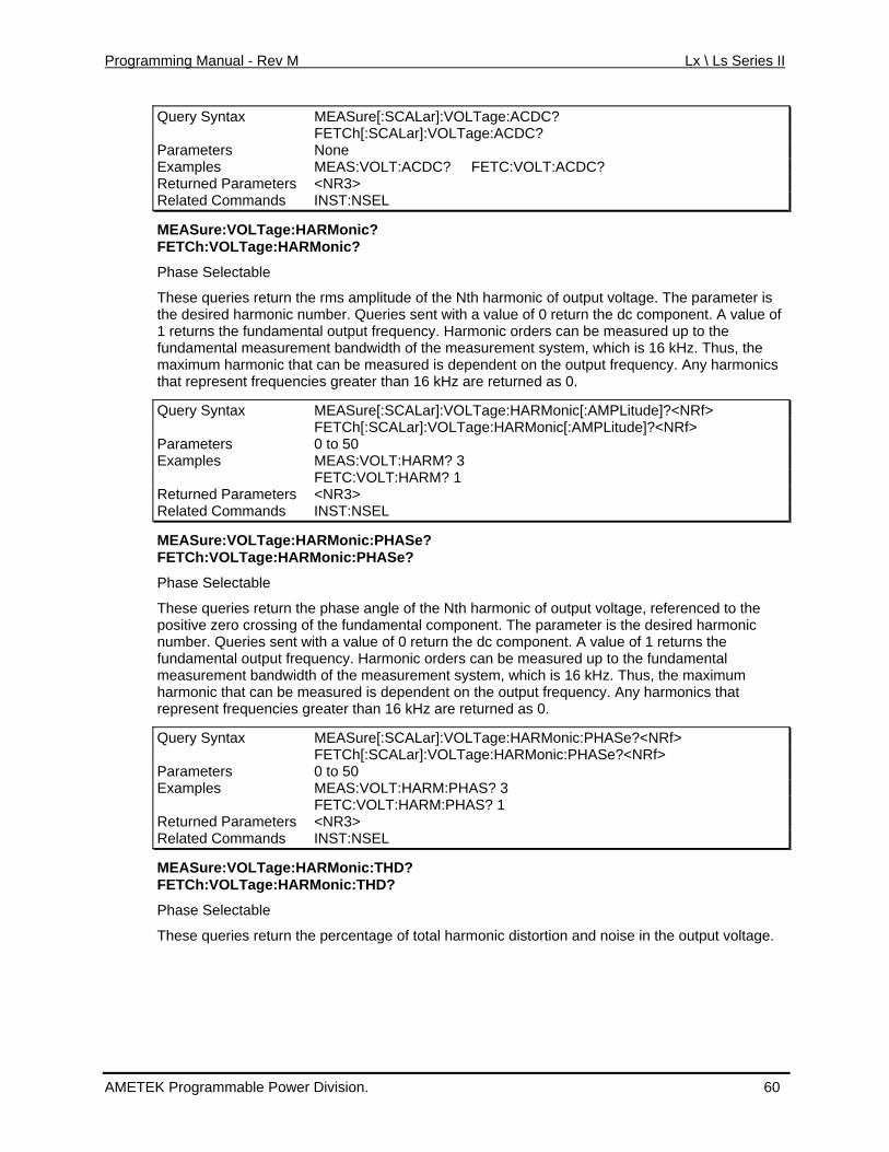
Programming Manual - Rev M Lx \ Ls Series II
Query Syntax MEASure[:SCALar]:VOLTage:ACDC? FETCh[:SCALar]:VOLTage:ACDC? Parameters None Examples MEAS:VOLT:ACDC? FETC:VOLT:ACDC? Returned Parameters <NR3> Related Commands INST:NSEL
MEASure:VOLTage:HARMonic?
meter is rmonic number. Queries sent with a value of 0 return the dc component. A value of
MEASure[:SCALar]:VOLTage:HARMonic[:AMPLitude]?<NRf>
FETCh:VOLTage:HARMonic?
Phase Selectable
These queries return the rms amplitude of the Nth harmonic of output voltage. The parathe desired ha1 returns the fundamental output frequency. Harmonic orders can be measured up to the fundamental measurement bandwidth of the measurement system, which is 16 kHz. Thus, the maximum harmonic that can be measured is dependent on the output frequency. Any harmonics that represent frequencies greater than 16 kHz are returned as 0.
Query Syntax FETCh[:SCALar]:VOLTage:HARMonic[:AMPLitude]?<NRf> Parameters 0 to 50 Examples MEAS:VOLT:HARM? 3 FETC:VOLT:HARM? 1 Returned Parameters <NR3> Related Commands INST:NSEL
MEASure:VOLTage:HARMonic:PHASe? FETCh:VOLTage:HARMonic:PHASe?
Phase Selectable
These queries return the phase angle of the Nth harmonic of output voltage, referenced to the positive zero crossing of the fundamental component. The parameter is the desired harmonic number. Queries sent with a value of 0 return the dc component. A value of 1 returns the fundamental output frequency. Harmonic orders can be measured up to the fundamental measurement bandwidth of the measurement system, which is 16 kHz. Thus, the maximum harmonic that can be measured is dependent on the output frequency. Any harmonics that represent frequencies greater than 16 kHz are returned as 0.
Query Syntax MEASure[:SCALar]:VOLTage:HARMonic:PHASe?<NRf> FETCh[:SCALar]:VOLTage:HARMonic:PHASe?<NRf> Parameters 0 to 50 Examples MEAS:VOLT:HARM:PHAS? 3 FETC:VOLT:HARM:PHAS? 1 Returned Parameters <NR3> Related Commands INST:NSEL
MEASure:VOLTage:HARMonic:THD? FETCh:VOLTage:HARMonic:THD?
Phase Selectable
These queries return the percentage of total harmonic distortion and noise in the output voltage.
AMETEK Programmable Power Division. 60
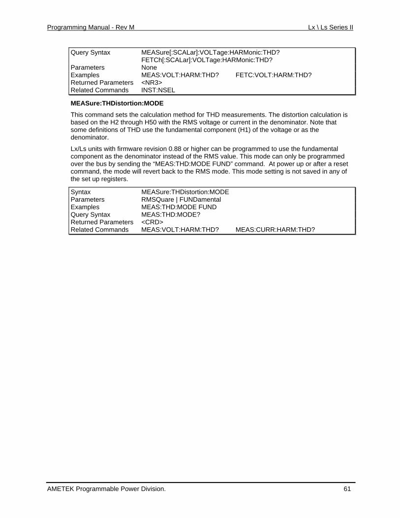
Programming Manual - Rev M Lx \ Ls Series II
Query Syntax MEASure[:SCALar]:VOLTage:HARMonic:THD? FETCh[:SCALar]:VOLTage:HARMonic:THD? Parameters None Examples MEAS:VOLT:HARM:THD? FETC:VOLT:HARM:THD? Returned Parameters <NR3> Related Commands INST:NSEL
MEASure:THDistortion:MODE
n is denominator. Note that
fundamental ominator instead of the RMS value. This mode can only be programmed
t power up or after a reset d in any of
egisters.
This command sets the calculation method for THD measurements. The distortion calculatiobased on the H2 through H50 with the RMS voltage or current in thesome definitions of THD use the fundamental component (H1) of the voltage or as the denominator.
Lx/Ls units with firmware revision 0.88 or higher can be programmed to use thecomponent as the denover the bus by sending the “MEAS:THD:MODE FUND” command. Acommand, the mode will revert back to the RMS mode. This mode setting is not savethe set up r
Syntax MEASure:THDistortion:MODE Parameters RMSQuare | FUNDamental Examples MEAS:THD:MODE FUND Query Syntax MEAS:THD:MODE? Returned Parameters <CRD> Related Commands MEAS:VOLT:HARM:THD? MEAS:CURR:HARM:THD?
AMETEK Programmable Power Division. 61
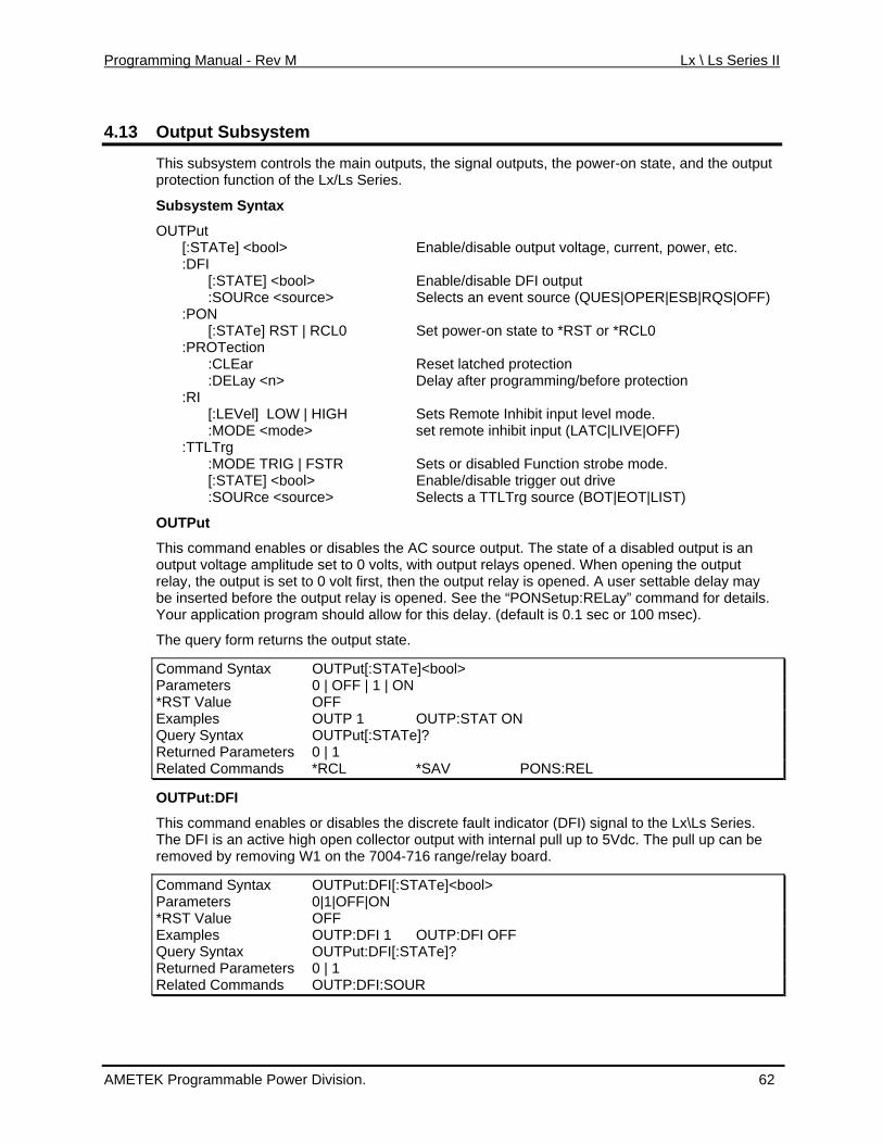
Programming Manual - Rev M Lx \ Ls Series II
4.13 Output Subsystem
This trols l outputs, the power-on state, and the output pro f the
Sub tax
OU e] <bool> output voltage, current, power, etc. able DFI output
sour vent source (QUES|OPER|ESB|RQS|OFF)
Te] RST | tion
protection
Sets Remote Inhibit input level mode. set remote inhibit input (LATC|LIVE|OFF)
TATE] <bool> Enable/disable trigger out drive
OUTPut
This and enables output voltage amplitude ing the output
is opened. A user settable delay may the o
ay. (default is 0.1 sec or 100 msec).
e]<bool>
subsystem con the main outputs, the signatection function o Lx/Ls Series.
system Syn
TPut [:STAT Enable/disable:DFI [:STATE] <bool> Enable/dis
:SOURce < ce> Selects an e :PON
Set power-on state to *RST or *RCL0 [:STA RCL0ec :PROT
latched :CLEar ResetDelay after programming/before protection :DELay <n>
:RI [:LEVel] LOW | HIGH :MODE <mode> :TTLTrg :MODE TRIG | FSTR Sets or disabled Function strobe mode. [:S
:SOURce <source> Selects a TTLTrg source (BOT|EOT|LIST)
comm or disables the AC source output. The state of a disabled output is an set to 0 volts, with output relays opened. When open
relay, the output is set to 0 volt first, then the output relay efore pened. See the “PONSetup:RELay” command for details. be inserted b utput relay is o
Your application program should allow for this del
The query form returns the output state.
Command Syntax OUTPut[:STATParameters 0 | OFF | 1 | ON *RST Value OFF Examples OUTP 1 OUTP:STAT ON Query Syntax OUTPut[:STATe]? Returned Parameters 0 | 1 Related Commands *RCL *SAV PONS:REL
OUTPut:DFI
This command enables or disables the discrete fault indicator (DFI) signal to the Lx\Ls Series. The DFI is an active high open collector output with internal pulremoved by removing W1 on the 7004-716 range/relay board.
l up to 5Vdc. The pull up can be
Command Syntax OUTPut:DFI[:STATe]<bool> Parameters 0|1|OFF|ON *RST Value OFF Examples OUTP:DFI 1 OUTP:DFI OFF Query Syntax OUTPut:DFI[:STATe]? Returned Parameters 0 | 1 Related Commands OUTP:DFI:SOUR
AMETEK Programmable Power Division. 62
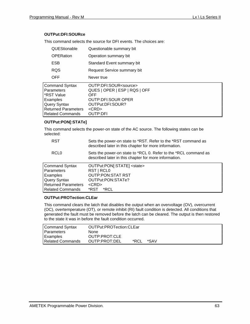
Programming Manual - Rev M Lx \ Ls Series II
OUTPut:DFI:SOURce
This command selects the source for DFI events. The choices are:
QUEStionable Questionable summary bit
OPERation Operation summary bit
ESB Standard Event summary bit
RQS Request Service summary bit
OFF Never true
Command Sy OUTP:DFI:SOURntax <source> Parameters QUES | OPER | ESP | RQS | OFF *RST Value OFF Examples OUTP:DFI:SOUR OPER Query Syntax OUTPut:DFI:SOUR? Returned Parameters <CRD> Related Commands OUTP:DFI
OUTPut:PON[:STATe]
This command selects the power-on state of the AC source. The following states can be selected:
RST Sets the power-on state to *RST. Refer to the *RST command as is chapter for more information.
r-on state to *RCL 0. Refer to the *RCL command as ed later in this chapter for more information.
described later in th
RCL0 Sets the powedescrib
Command Syn OUTPut:PON[:Stax TATE] <state> Parameters RST | RCL0 Examples OUTP:PON:STAT RST Query Syntax OUTPut:PON:STATe? Returned Parameters <CRD> Related Commands *RST *RCL
OUTPut:PROTection:CLEar
This clears th(OC), overtemperature ( that gen the fault mus ed to th e it was in bef
Command Syntax
command e latch that disables the output when an overvoltage (OV), overcurrent OT), or remote inhibit (RI) fault condition is detected. All conditions
erated t be removed before the latch can be cleared. The output is then restore stat ore the fault condition occurred.
OUTPut:PROTection:CLEar Parameters None Examples OUTP:PROT:CLE Related Commands OUTP:PROT:DEL *RCL *SAV
AMETEK Programmable Power Division. 63
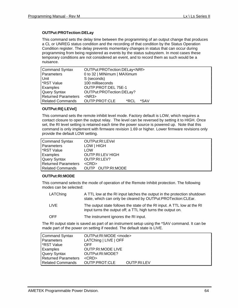
Programming Manual - Rev M Lx \ Ls Series II
OUTPut:PROTection:DELay
This command sets the delay time between the programming of an output change that produces a CL or UNREG status condition and the recording of that condition by the Status Operation Condition register. The delay prevents momentary changes in status that can occur during programming from being registered as events by the status subsystem. In most cases these temporary conditions are not considered an event, and to record them as such would be a nuisance.
Command Syntax OUTPut:PROTection:DELay<NRf> Parameters 0 to 32 | MINimum | MAXimum Unit S (seconds) *RST Value 100 milliseconds Examples OUTP:PROT:DEL 75E-1 Query Syntax OUTPut:PROTection:DELay? Returned Parameters <NR3> Related Commands OUTP:PROT:CLE *RCL *SAV
OUTPut:RI[:LEVel]
This command sets the remote inhibit level mode. Factory default is LOW, which requires a contact closure to open the output relay. The level can be reversed by setting it to HIGH. Once set, the RI level setting is retained each time the power source is powered up. Note that this command is only implement with firmware revision 1.69 or higher. Lower firmware revisions only provide the default LOW setting.
Command Syntax OUTPut:RI:LEVel Parameters LOW | HIGH *RST Value LOW Examples OUTP:RI:LEV HIGH Query Syntax OUTP:RI:LEV? Returned Parameters <CRD> Related Commands OUTP OUTP:RI:MODE
OUTPut:RI:MODE
This command selects the mode of operation of the Remote Inhibit protection. The following modes can be selected:
LATChing A TTL low at the RI input latches the output in the protection shutdown state, which can only be cleared by OUTPut:PROTection:CLEar.
LIVE The output state follows the state of the RI input. A TTL low at the RI input turns the output off; a TTL high turns the output on.
OFF The instrument ignores the RI input.
The RI output state is saved as part of an instrument setup using the *SAV command. It can be made part of the power on setting if needed. The default state is LIVE.
Command Syntax OUTPut:RI:MODE <mode> Parameters LATChing | LIVE | OFF *RST Value OFF Examples OUTP:RI:MODE LIVE Query Syntax OUTPut:RI:MODE? Returned Parameters <CRD> Related Commands OUTP:PROT:CLE OUTP:RI:LEV
AMETEK Programmable Power Division. 64
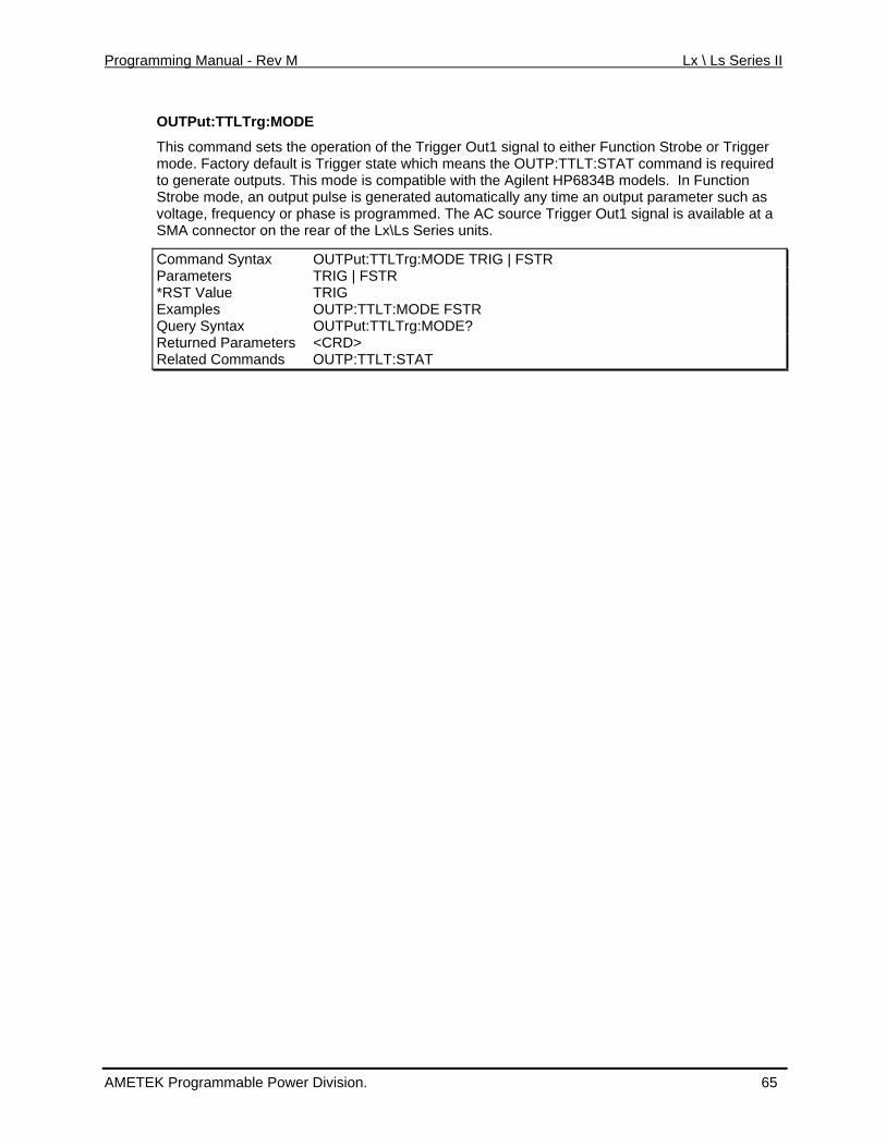
Programming Manual - Rev M Lx \ Ls Series II
OUTPut:TTLTrg:MODE
This command sets the operation of the Trigger Out1 signal to either Function Strobe or Triggemode. Factory default is Trigger state which means th
r e OUTP:TTLT:STAT command is required
ny time an output parameter such as C source Trigger Out1 signal is available at a
or on the r S
tax G | FSTR
to generate outputs. This mode is compatible with the Agilent HP6834B models. In Function Strobe mode, an output pulse is generated automatically avoltage, frequency or phase is programmed. The ASMA connect ear of the Lx\Ls eries units.
Command Syn OUTPut:TTLTrg:MODE TRIParameters TRIG | FSTR *RST Value TRIG Examples OUTP:TTLT:MODE FSTR Query Syntax OUTPut:TTLTrg:MODE? Returned Parameters <CRD> Related Commands OUTP:TTLT:STAT
AMETEK Programmable Power Division. 65
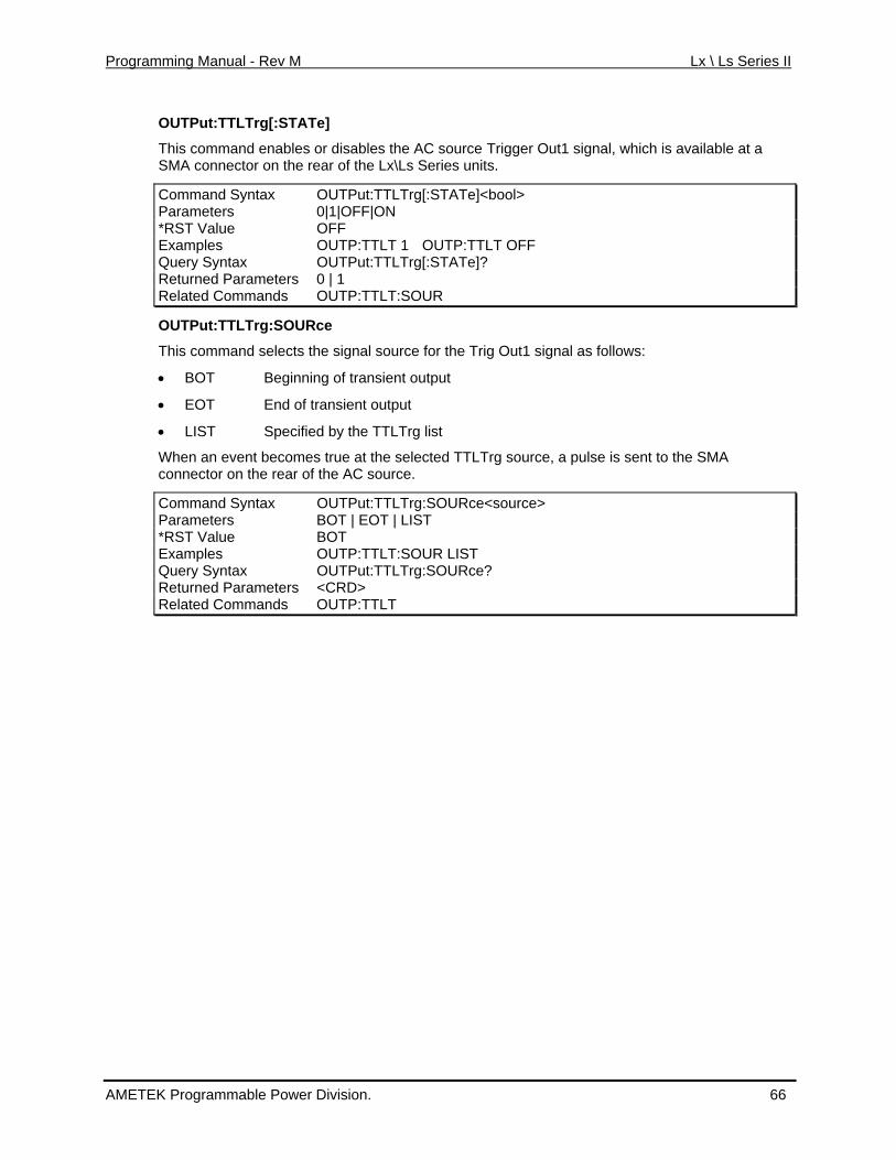
Programming Manual - Rev M Lx \ Ls Series II
OUTPut:TTLTrg[:STATe]
This command enables or disables the AC source Trigger Out1 signal, which is available at a SMA connector on the rear of the Lx\Ls Series units.
Command Syntax OUTPut:TTLTrg[:STATe]<bool> Parameters 0|1|OFF|ON *RST Value OFF Examples OUTP:TTLT 1 OUTP:TTLT OFF Query Syntax OUTPut:TTLTrg[:STATe]? R urned Paret ameters 0 | 1 Related Commands OUTP:TTLT:SOUR
OUTPut:TTLTrg:SOURce
This command selects the signal source for the Trig Out1 signal as follows:
• BOT Beginning of transient output
• EOT End of transient output
• LIST Specified by the TTLTrg list
When an event becomes true at the selected TTLTrg source, a pulse is sent to the SMA connector on the rear of the AC source.
Command Syntax OUTPut:TTLTrg:SOURce<source> Parameters BOT | EOT | LIST *RST Value BOT Examples OUTP:TTLT:SOUR LIST Query Syntax OUTPut:TTLTrg:SOURce? Returned Parameters <CRD> Related Commands OUTP:TTLT
AMETEK Programmable Power Division. 66
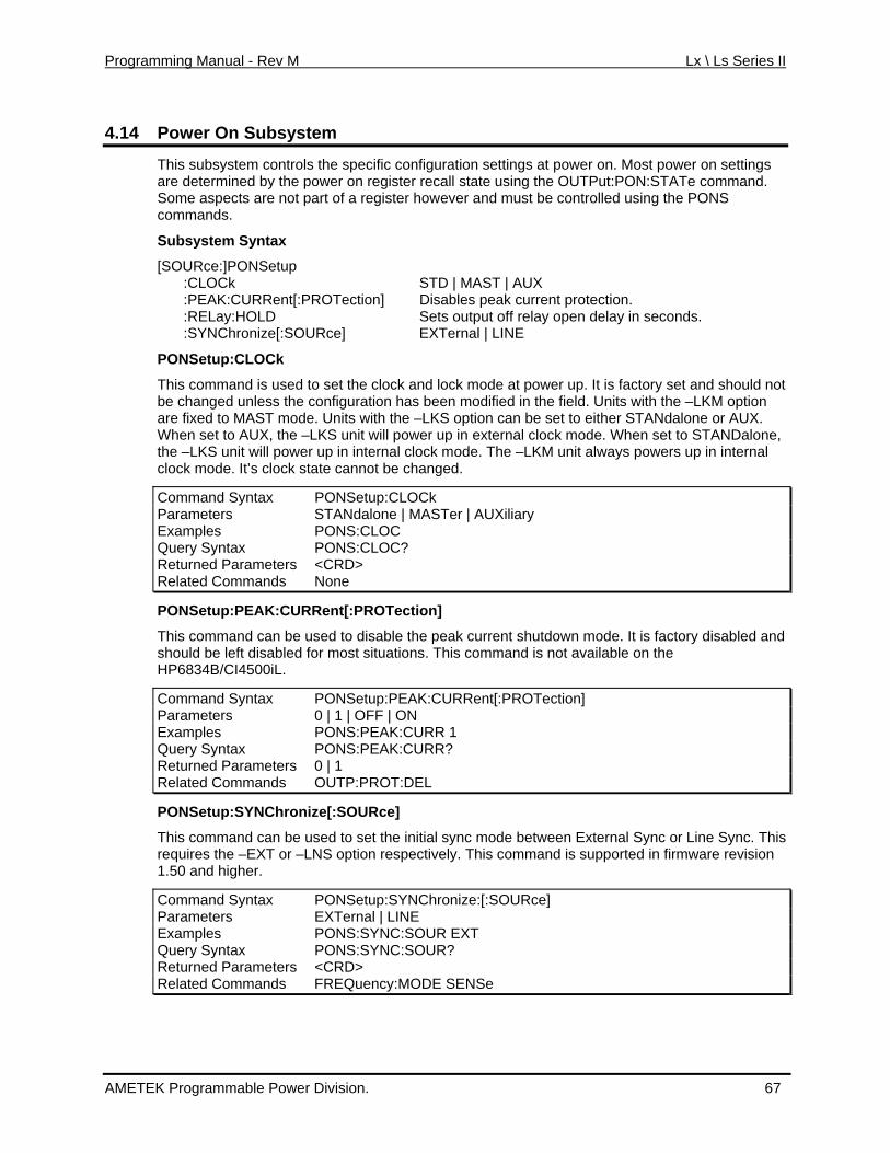
Programming Manual - Rev M Lx \ Ls Series II
4.14 Power On Subsystem
This subsystem controls the specific configuration settings at power on. Most power on settings are determined by the power on register recall state using the OUTPut:PON:STATe command. Some aspects are not part of a register however and must be controlled using the PONS commands.
Subsystem Syntax
[SOURce:]PONSetup :CLOCk STD | MAST | AUX :PEAK:CURRent[:PROTection] Disables peak current protection. :RELay:HOLD Sets output off relay open delay in seconds. :SYNChronize[:SOURce] EXTernal | LINE
PONSetup:CLOCk
This command is used to set the clock and lock mode at power up. It is factory set and should not d in the field. Units with the –LKM option n be set to either STANdalone or AUX.
–L wer up in external clock mode. When set to STANDalone, r rnal clo
Command Syntax PONSetup:CLOCk
be changed u onfiguration has beennless the c modifieare fixed to MAST mode. Units with the –LKS option caWhen set to AU KS unit will poX, the the –LKS unit will powe up in inte ck mode. The –LKM unit always powers up in internal clock mode. It’s clock state cannot be changed.
Parameters STANdalone | MASTer | AUXiliary Examples PONS:CLOC Query Syntax PONS:CLOC? Returned Parameters <CRD> Related Commands None
PONSetup:PEAK:CURRent[:PROTection]
This command can be used to disable the peak current shutdown mode. It is factory disabled and should be left disabled for most situations. This command is not available on the HP6834B/CI4500iL.
Command Syntax PONSetup:PEAK:CURRent[:PROTection] Parameters 0 | 1 | OFF | ON Examples PONS:PEAK:CURR 1 Query Syntax PONS:PEAK:CURR? Returned Parameters 0 | 1 Related Commands OUTP:PROT:DEL
PONSetup:SYNChronize[:SOURce]
This command can be used to set the initial sync mode between External Sync or Line Sync. This requires the –EXT or –LNS option respectively. This command is supported in firmware revision 1.50 and higher.
Command Syntax PONSetup:SYNChronize:[:SOURce] Parameters EXTernal | LINE Examples PONS:SYNC:SOUR EXT Query Syntax PONS:SYNC:SOUR? Returned Parameters <CRD> Related Commands FREQuency:MODE SENSe
AMETEK Programmable Power Division. 67
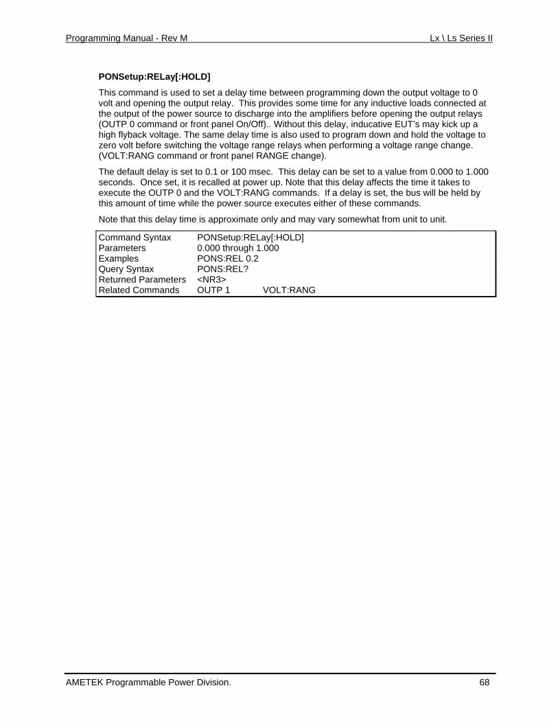
Programming Manual - Rev M Lx \ Ls Series II
PONSetup:RELay[:HOLD]
This command is used to set a delay time between programming down the output voltage to 0
the power source to discharge into the amplifiers before opening the output relays r front panel On/Off).. Without this delay, inducative EUT’s may kick up a The same delay time is also used to program down and hold the voltage to
before switching the voltage range relays when performing a voltage range change.
is et to 0.1 or 100 msec. This
is mo nt e power source exec
ot tha is approximate only and may vary somewhat from unit to unit.
PONSetup:RELay[:HOLD]
volt and opening the output relay. This provides some time for any inductive loads connected atthe output of(OUTP 0 command ohigh flyback voltage. zero volt(VOLT:RANG command or front panel RANGE change).
T ult delay s delay can be set to a value from 0.000 to 1.000 seconds. Once set, it is recalled at power up. Note that this delay affects the time it takes to
he defa
execute the OUTP 0 and the VOLT:RANG commands. If a delay is set, the bus will be held by th a u of time while th utes either of these commands.
N e t this delay time
Command Syntax Parameters 0.000 through 1.000 Examples PONS:REL 0.2 Query Syntax PONS:REL? Returned Parameters <NR3> Related Commands OUTP 1 VOLT:RAN G
AMETEK Programmable Power Division. 68
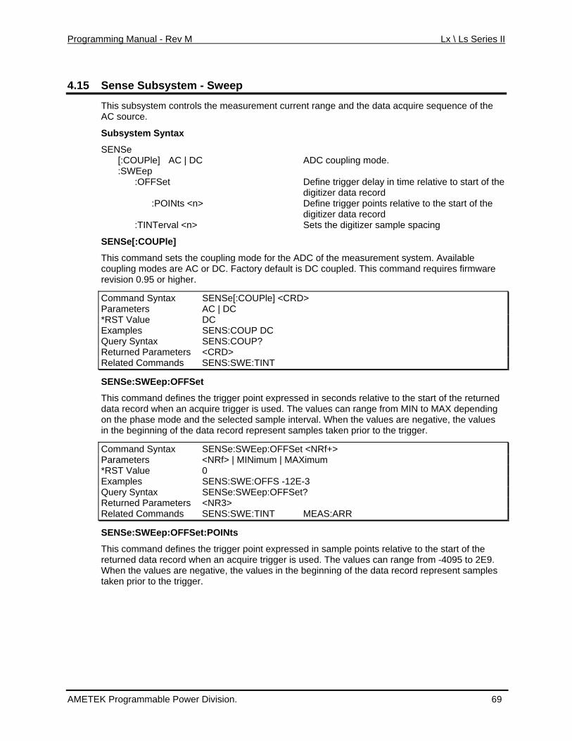
Programming Manual - Rev M Lx \ Ls Series II
4.15 system Sense Sub - Sweep
This subsystem controls the measurement current range and the data acquire sequence of the
SENSe ADC coupling mode.
nts relative to the start of the
<n> itizer sample spacing
Ple]
asurement system. Available This command requires firmware
AC source.
Subsystem Syntax
[:COUPle] AC | DC :SWEep :OFFSet Define trigger delay in time relative to start of the
digitizer data record :POINts <n> Define trigger poi
digitizer data record :TINTerval Sets the dig
SENSe[:COU
This command sets the coupling mode for the ADC of the me coupled.coupling modes are AC or DC. Factory default is DC
revision 0.95 or higher.
Command Syntax SENSe[:COUPle] <CRD>Parameters AC | DC *RST Value DC Examples SENS:COUP DC Query Syntax SENS:COUP? Returned Parameters <CRD> Related Commands SENS:SWE:TINT
SENSe:SWEep:OFFSet
This command defines the trigger point expressed in seconds relative to the start of the returned data record when an acquire trigger is used. The values can range from MIN to MAX depending on the phase mode and the selected sample interval. When the values are negative, the values in the beginning of the data record represent samples taken prior to the trigger.
Command Syntax SENSe:SWEep:OFFSet <NRf+> Parameters <NRf> | MINimum | MAXimum *RST Value 0 Examples SENS:SWE:OFFS -12E-3 Query Syntax SENSe:SWEep:OFFSet? Returned Parameters <NR3> Related Commands SENS:SWE:TINT MEAS:ARR
SENSe:SWEep:OFFSet:POINts
This command defines the trigger point expressed in sample points relative to the start of the returned data record when an acquire trigger is used. The values can range from -4095 to 2E9. When the values are negative, the values in the beginning of the data record represent samples taken prior to the trigger.
AMETEK Programmable Power Division. 69
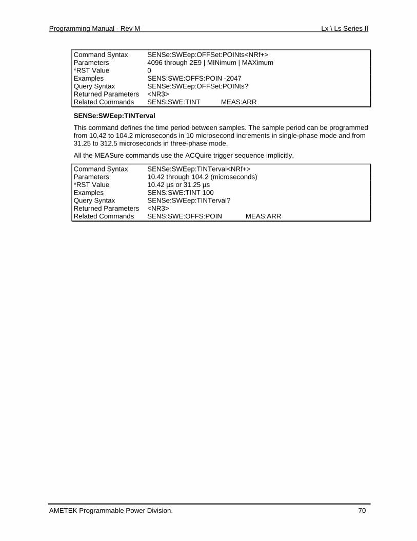
Programming Manual - Rev M Lx \ Ls Series II
Command Syntax SENSe:SWEep:OFFSet:POINts<NRf+> Parameters 4096 through 2E9 | MINimum | MAXimum *RST Value 0 Examples SENS:SWE:OFFS:POIN -2047 Query Syntax SENSe:SWEep:OFFSet:POINts? Returned Parameters <NR3> Related Commands SENS:SWE:TINT MEAS:ARR
SENSe:SWEep:TINTerval
ple period can be programmed single-phase mode and from
the AC
Syntax SENSe:SWEep:TINTerval<NRf+>
This command defines the time period between samples. The samfrom 10.42 to 104.2 microseconds in 10 microsecond increments in31.25 to 312.5 microseconds in three-phase mode.
All the MEASure commands use Quire trigger sequence implicitly.
Command Parameters 10.42 through 104.2 (microseconds) *RST Value 10.42 µs or 31.25 µs Examples SENS:SWE:TINT 100 Query Syntax SENSe:SWEep:TINTerval? Returned Parameters <NR3> Related Commands SENS:SWE:OFFS:POIN MEAS:ARR
AMETEK Programmable Power Division. 70
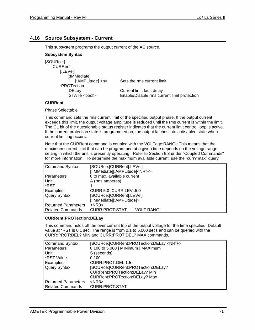
Programming Manual - Rev M Lx \ Ls Series II
4.16 nt Source Subsystem - Curre
This subsystem programs the output current of the AC source.
Subsystem Syntax
[SOURce:] CURRent [:LEVel] [:IMMediate] [:AMPLitude] <n> Sets the rms current limit
DELay limit fault delay TATe <bool> Enable/Disable rms current limit protection
e he specified output phase. If the output current exceeds this limit, the output voltage amplitude is reduced until the rms current is within the limit. The CL bit of the questionable status register indicates that the current limit control loop is active. If the current protection state is programmed on, the output latches into a disabled state when current limiting occurs.
Note that the CURRent command is coupled with the VOLTage:RANGe.This means that the maximum current limit that can be programmed at a given time depends on the voltage range setting in which the unit is presently operating. Refer to Section 6.3 under "Coupled Commands" for more information. To determine the maximum available current, use the “curr? max” query
Command Syntax [SOURce:]CURRent[:LEVel]
:PROTection : Current :S
CURRent
Phase Selectable
This command sets th rms current limit of t
[:IMMediate][:AMPLitude]<NRf+> Parameters 0 to max. available current Unit: A (rms amperes) *RST 1 Examples CURR 5.0 CURR:LEV .5.0 Query Syntax [SOURce:]CURRent[:LEVel] [:IMMediate][:AMPLitude]? Returned Parameters <NR3> Related Commands CURR:PROT:STAT VOLT:RANG
CURRent:PROTection:DELay
This command holds off the over current trip of the output voltage for the time specified. Default value at *RST is 0.1 sec. The range is from 0.1 to 5.000 secs and can be queried with the CURR:PROT:DEL? MIN and CURR:PROT:DEL? MAX commands.
Command Syntax [SOURce:]CURRent:PROTection:DELay <NRf+> Parameters 0.100 to 5.000 | MINimum | MAXimum Unit: S (seconds) *RST Value 0.100 Examples CURR:PROT:DEL 1.5 Query Syntax [SOURce:]CURRent:PROTection:DELay?
CURRent:PROTection:DELay? Min CURRent:PROTection:DELay? Max
Returned Parameters <NR3> Related Commands CURR:PROT:STAT
AMETEK Programmable Power Division. 71
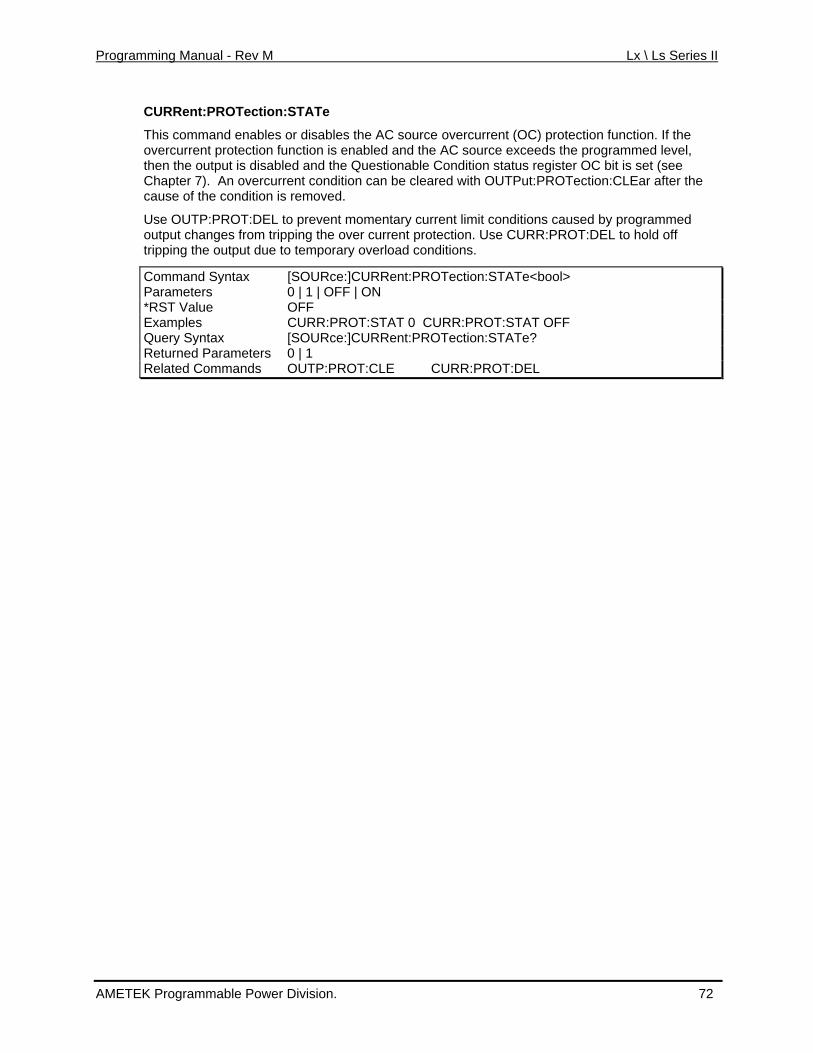
Programming Manual - Rev M Lx \ Ls Series II
CURRent:PROTection:STATe
This command enables or disables the AC source overcurrent (OC) protection function. If the eds the programmed level,
sabled and the Questionable Condition status register OC bit is set (see current condition can be cleared with OUTPut:PROTection:CLEar after the
condition is removed.
nditions caused by programmed URR:PROT:DEL to hold off
overcurrent protection function is enabled and the AC source excethen the output is diChapter 7). An overcause of the
Use OUTP:PROT:DEL to prevent momentary current limit cooutput changes from tripping the over current protection. Use Ctripping the output due to temporary overload conditions.
Command Syntax [SOURce:]CURRent:PROTection:STATe<bool> Parameters 0 | 1 | OFF | O N*RST Value OFF E CURR:PROT:STAT 0 CURR:PROT:STAT OFF xamples Q r yntax [SOURce:]CURRent:PROTection:STATe? ue y SReturned Parameters 0 | 1 Related Commands OUTP:PROT:CLE CURR:PROT:DEL
AMETEK Programmable Power Division. 72
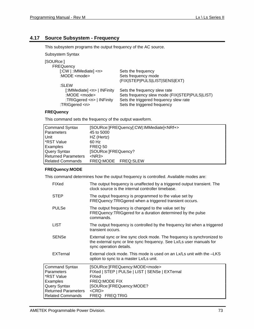
Programming Manual - Rev M Lx \ Ls Series II
4.17 m - Frequency Source Subsyste
This subsystem programs the output frequency of the AC source.
Subsystem Syntax
[SOURce:] FREQuency [:CW | :IMMediate] <n> Sets the frequency Sets fre:MODE <mode> quency mode
cy slew rate
frequenche d frequency slew rate
Sets the triggered frequency
ency of the output waveform.
Command Syntax
(FIX|STEP|PULS|LIST|SENS|EXT) :SLEW [:IMMediate] <n> | INFinity Sets the frequen :MODE <mode> Sets y slew mode (FIX|STEP|PULS|LIST) :TRIGgered <n> | INFinity Sets t triggere :TRIGgered <n>
FREQuency
This command sets the frequ
[SOURce:]FREQuency[:CW|:IMMediate]<NRf+> Parameters 45 to 5000 Unit HZ (Hertz) *RST Value 60 Hz Examples FREQ 50 Query Syntax [SOURce:]FREQuency? Returned Parameters <NR3> Related Commands FREQ:MODE FREQ:SLEW
FREQuency:MODE
able modes are:
cted by a triggered output transient. The ebase.
the value set by n a triggered transient occurs.
PULSe The output frequency is changed to the value set by ncy:TRIGgered for a duration determined by the pulse
cy is synchronized to uency. See Lx/Ls user manuals for
l is mode is used on an Lx/Ls unit with the –LKS
tax
This command determines how the output frequency is controlled. Avail
FIXed The output frequency is unaffeclock source is the internal controller tim
STEP The output frequency is programmed to FREQuency:TRIGgered whe
FREQuecommands.
LIST The output frequency is controlled by the frequency list when a triggeredtransient occurs.
SENSe External sync or line sync clock mode. The frequenthe external sync or line sync freqsync operation details.
EXTerna External clock mode. Thoption to sync to a master Lx/Ls unit.
Command Syn [SOURce:]FREQuency:MODE<mode>Parameters FIXed | STEP | PULSe | LIST | SENSe | EXTernal *RST Value FIXed Examples FREQ:MODE FIX Query Syntax [SOURce:]FREQuency:MODE? Returned Parameters <CRD> Related Commands FREQ FREQ:TRIG
AMETEK Programmable Power Division. 73
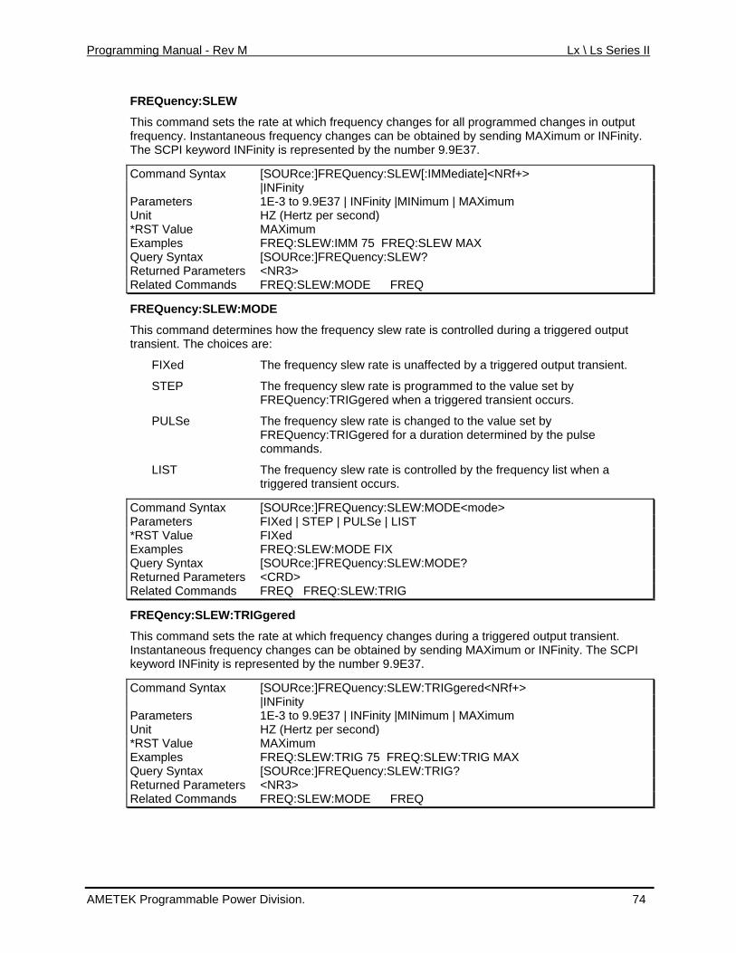
Programming Manual - Rev M Lx \ Ls Series II
FREQuency:SLEW
This command sets the rate at which frequency changes for all programmed changes in outputfrequency. Instan
taneous frequency changes can be obtained by sending MAXimum or INFinity.
ntax Rf+>
The SCPI keyword INFinity is represented by the number 9.9E37.
Command Sy [SOURce:]FREQuency:SLEW[:IMMediate]<N |INFinity Parameters 1E-3 to 9.9E37 | INFinity |MINimum | MAXimum Unit HZ (Hertz per second) *RST Value MAXimum Examples FREQ:SLEW:IMM 75 FREQ:SLEW MAX Query Syntax [SOURce:]FREQuency:SLEW? Returned Parameters <NR3> Related Commands FREQ:SLEW:MODE FREQ
FREQuency:SLEW:MODE
This command determines how the frequency slew rate is controlled during a triggered output transient. The choices are:
FIXed The frequency slew rate is unaffected by a triggered output transient.
STEP The frequency slew rate is programmed to the value set by FREQuency:TRIGgered when a triggered transient occurs.
PULSe The frequency slew rate is changed to the value set by FREQuency:TRIGgered for a duration determined by the pulse commands.
LIST The frequency slew rate is controlled by the frequency list when a triggered transient occurs.
Command Syntax [SOURce:]FREQuency:SLEW:MODE<mode> Parameters FIXed | STEP | PULSe | LIST *RST Value FIXed Examples FREQ:SLEW:MODE FIX Query Syntax [SOURce:]FREQuency:SLEW:MODE? Returned Parameters <CRD> Related Commands FREQ FREQ:SLEW:TRIG
FREQency:SLEW:TRIGgered
This command sets the rate at which frequency changes during a triggered output transient. Instantaneous frequency changes can be obtained by sending MAXimum or INFinity. The SCPI keyword INFinity is represented by the number 9.9E37.
Command Syntax [SOURce:]FREQuency:SLEW:TRIGgered<NRf+> |INFinity Parameters 1E-3 to 9.9E37 | INFinity |MINimum | MAXimum Unit HZ (Hertz per second) *RST Value MAXimum Examples FREQ:SLEW:TRIG 75 FREQ:SLEW:TRIG MAX Query Syntax [SOURce:]FREQuency:SLEW:TRIG? Returned Parameters <NR3> Related Commands FREQ:SLEW:MODE FREQ
AMETEK Programmable Power Division. 74
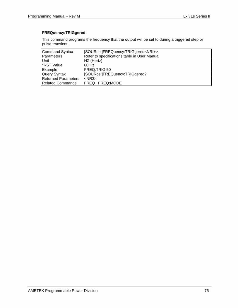
Programming Manual - Rev M Lx \ Ls Series II
FREQuency:TRIGgered
This command programs the frequency that the output will be set to during a triggered step or
[SOURce:]FREQuency:TRIGgered<NRf+>
pulse transient.
Command Syntax Parameters Refer to specifications table in User Manual Unit HZ (Hertz) *RST Value 60 Hz Example FREQ:TRIG 50 Query Syntax [SOURce: uency:TRIGgered? ]FREQReturned Parameters <NR3> Related Commands FREQ FREQ:MODE
AMETEK Programmable Power Division. 75
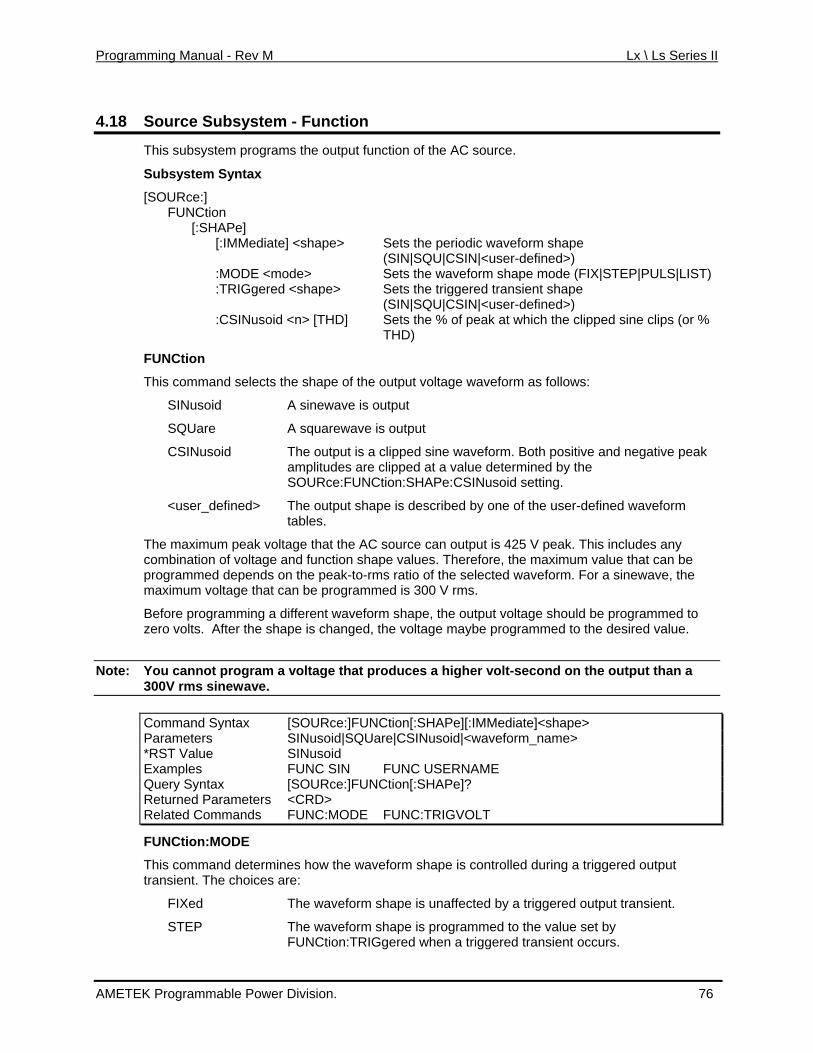
Programming Manual - Rev M Lx \ Ls Series II
4.18 Source Subsystem - Function
This stem program
rm shape (SIN|SQU|CSIN|<user-defined>)
mo waveform shape mode (FIX|STEP|PULS|LIST) :TRIGgered <shape> Sets the triggered transient shape
(SIN|SQU|CSIN|<user-defined>)
FUN
This command selects the shape of the output voltage waveform as follows:
SQUare
CSINusoid
:FUNCtion:SHAPe:CSINusoid setting.
re, the maximum value that can be programmed depends on the peak-to-rms ratio of the selected waveform. For a sinewave, the
different waveform shape, the output voltage should be programmed to zero volts. After the shape is changed, the voltage maybe programmed to the desired value.
Note:
subsy s the output function of the AC source.
Subsystem Syntax
[SOURce:] FUNCtion [:SHAPe] [:IMMediate] <shape> Sets the periodic wavefo
:MODE < de> Sets the
:CSINusoid <n> [THD] Sets the % of peak at which the clipped sine clips (or % THD)
Ction
SINusoid A sinewave is output
A squarewave is output
The output is a clipped sine waveform. Both positive and negative peak amplitudes are clipped at a value determined by the SOURce
<user_defined> The output shape is described by one of the user-defined waveform tables.
The maximum peak voltage that the AC source can output is 425 V peak. This includes any combination of voltage and function shape values. Therefo
maximum voltage that can be programmed is 300 V rms.
Before programming a
You cannot vprogram a oltage that produces a higher volt-second on the output than a 300V rms sinewave.
Command Syntax [SOURce:]FUNCtion[:SHAPe][:IMMediate]<shape> Parameters SINusoid|SQUare|CSINusoid|<waveform_name> *RST Value SINusoid Examples FUNC SIN FUNC USERNAME Query Syntax [SOURce:]FUNCtion[:SHAPe]? Returned Parameters <CRD> Related Commands FUNC:MODE FUNC:TRIGVOLT
FUN
This command determines how the waveform shape is controlled during a triggered output
STEP The waveform shape is programmed to the value set by FUNCtion:TRIGgered when a triggered transient occurs.
Ction:MODE
transient. The choices are:
FIXed The waveform shape is unaffected by a triggered output transient.
AMETEK Programmable Power Division. 76
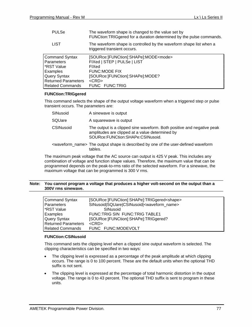
Programming Manual - Rev M Lx \ Ls Series II
PULSe The waveform shape is changed to the value set by FUNCtion:TRIGgered for a duration determined by the pulse commands.
he waveform shape list when a
e:]FUNCtion[:SHAPe]:MODE<mode>
LIST The waveform shape is controlled by ttriggered transient occurs.
Command Syntax [SOURcParameters FIXed | STEP | PULSe | LIST *RST Value FIXed Examples FUNC:MODE FIX Query Syntax [SOURce:]FUNCtion[:SHAPe]:MODE? Returned Parameters <CRD> Related Commands FUNC FUNC:TRIG
FUNCtion:TRIGgered
This command selects the shape of the output voltage waveform when a triggered step or pulse transient occurs. The parameters are:
SINusoid A sinewave is output
SQUare A squarewave is output
CSINusoid The output is a clipped sine waveform. Both positive and negative peak amplitudes are clipped at a value determined by SOURce:FUNCtion:SHAPe:CSINusoid.
<waveform_name> The output shape is described by one of the user-defined waveform tables.
The maximum peak voltage that the AC source can output is 425 V peak. This includes any combination of voltage and function shape values. Therefore, the maximum value that can be programmed depends on the peak-to-rms ratio of the selected waveform. For a sinewave, the maximum voltage that can be programmed is 300 V rms.
Note: You cannot program a voltage that produces a higher volt-second on the output than a 300V rms sinewave.
Command Syntax [SOURce:]FUNCtion[:SHAPe]:TRIGgered<shape> Parameters SINusoid|SQUare|CSINusoid|<waveform_name> *RST Value SINusoid Examples FUNC:TRIG SIN FUNC:TRIG TABLE1 Query Syntax [SOURce:]FUNCtion[:SHAPe]:TRIGgered? Returned Parameters <CRD> Related Commands FUNC FUNC:MODEVOLT
FUNCtion:CSINusoid
This command sets the clipping level when a clipped sine output waveform is selected. The clipping characteristics can be specified in two ways:
• The clipping level is expressed as a percentage of the peak amplitude at which clipping occurs. The range is 0 to 100 percent. These are the default units when the optional THD suffix is not sent.
• The clipping level is expressed at the percentage of total harmonic distortion in the output voltage. The range is 0 to 43 percent. The optional THD suffix is sent to program in these units.
AMETEK Programmable Power Division. 77
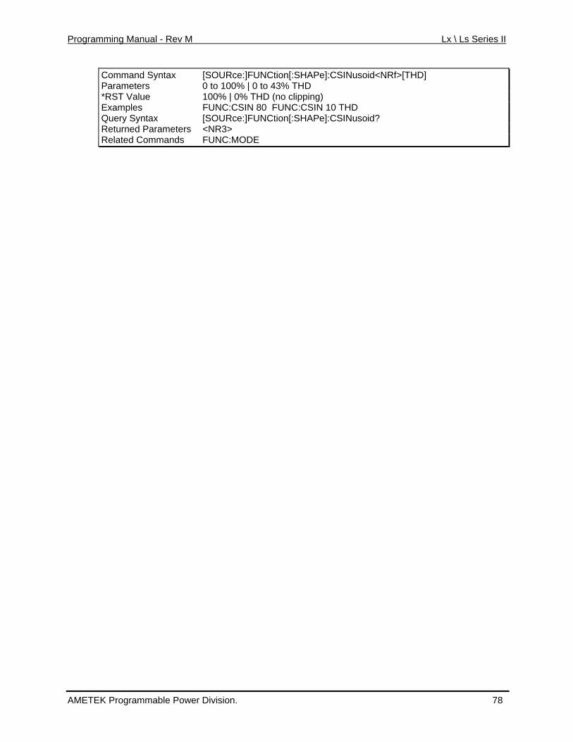
Programming Manual - Rev M Lx \ Ls Series II
Command Syntax [SOURce:]FUNCtion[:SHAPe]:CSINusoid<NRf>[THD] Parameters 0 to 100% | 0 to 43% THD *RST Value 100% | 0% THD (no clipping) Examples FUNC:CSIN 80 FUNC:CSIN 10 THD Query Syntax [SOURce:]FUNCtion[:SHAPe]:CSINusoid? Returned Parameters <NR3> Related Commands FUNC:MODE
AMETEK Programmable Power Division. 78
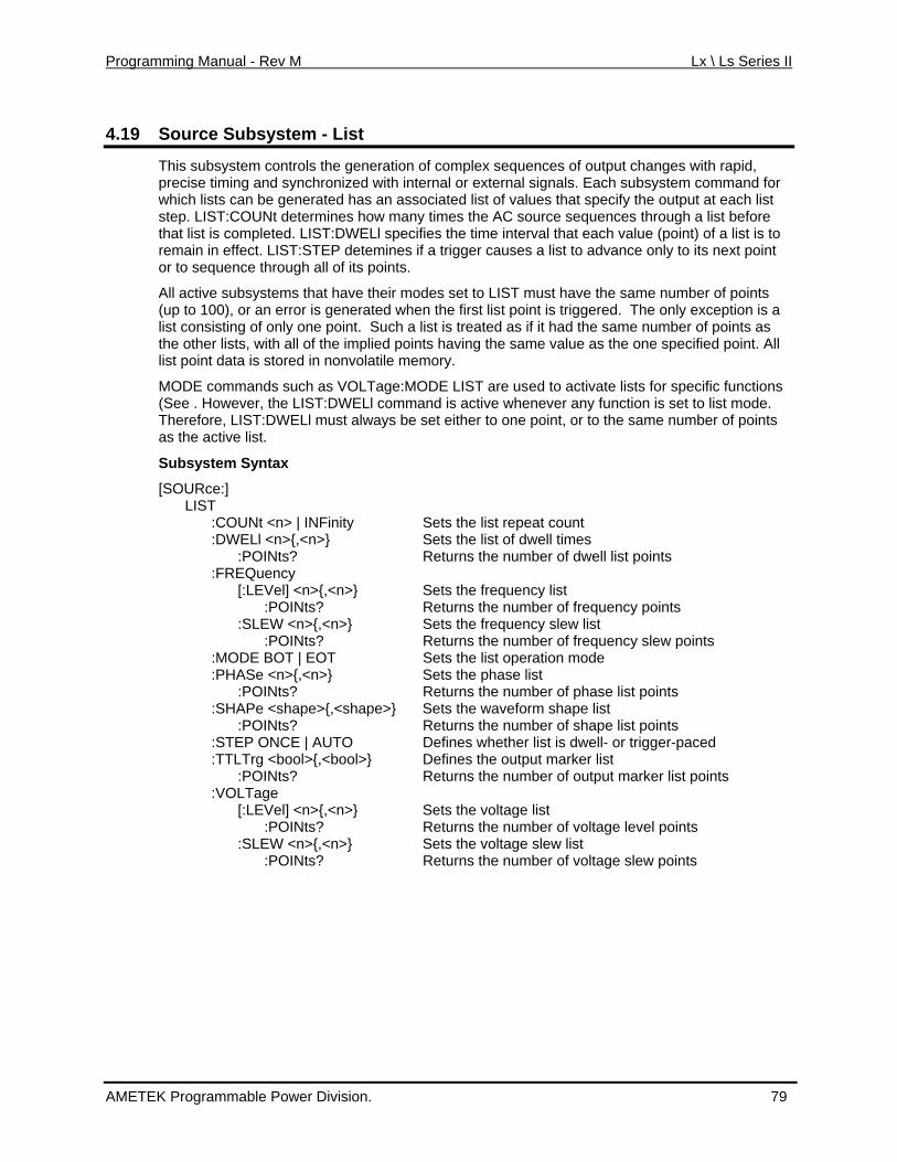
Programming Manual - Rev M Lx \ Ls Series II
4.19 system - List Source Sub
This subsystem controls the generation of complex sequences of output changes with rapid, precise timing and synchronized with internal or external signals. Each subsystem command for which lists can be generated has an associated list of values that specify the output at each list
rce sequences through a list before pleted. LI
a list to advance only to its next point
LIST must have the same number of points The only exception is a
with all of the implied points having the same value as the one specified point. All
list mode. s
t
[SO
:POINts? Returns the number of dwell list points
l] <n> :POINts ts
r of frequency slew points on mode
f phase list points
Returns the number of shape list points
rns the number of output marker list points ge
r of voltage level points
Returns the number of voltage slew points
step. LIST:COUNt determines how many times the AC southat list is com ST:DWELl specifies the time interval that each value (point) of a list is to remain in effect. LIST:STEP detemines if a trigger causesor to sequence through all of its points.
All active subsystems that have their modes set to(up to 100), or an error is generated when the first list point is triggered.list consisting of only one point. Such a list is treated as if it had the same number of points as the other lists,list point data is stored in nonvolatile memory.
MODE commands such as VOLTage:MODE LIST are used to activate lists for specific functions (See . However, the LIST:DWELl command is active whenever any function is set toTherefore, LIST:DWELl must always be set either to one point, or to the same number of pointas he active list.
Subsystem Syntax
URce:] LIST :COUNt <n> | INFinity Sets the list repeat count :DWELl <n>{,<n>} Sets the list of dwell times :FREQuency
:LEVe [ {,<n>} Sets the frequency list ? Returns the number of frequency poin
cy slew list :SLEW <n>{,<n>} Sets the frequen :POINts? Returns the numbe
list operati :MODE BOT | EOT Sets the Sets the phase list :PHASe <n>{,<n>}
:POINts? Returns the number o :SHAPe <shape>{,<shape>} Sets the waveform shape list :POINts? :STEP ONCE | AUTO Defines whether list is dwell- or trigger-paced :TTLTrg <bool>{,<bool>} Defines the output marker list :POINts? Retu :VOLTa
Sets the voltage list [:LEVel] <n>{,<n>} :POINts? Returns the numbe
Sets the voltage slew list :SLEW <n>{,<n>} :POINts?
AMETEK Programmable Power Division. 79
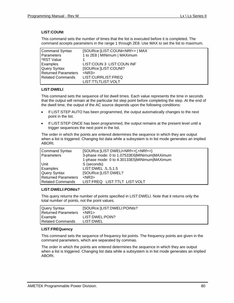
Programming Manual - Rev M Lx \ Ls Series II
LIST:COUNt
This command sets the number of times that the list is executed before it is completed. The se MAX to set the list to maximum.
NRf+> | MAX
command accepts parameters in the range 1 through 2E8. U
Command Syntax [SOURce:]LIST:COUNt<Parameters 1 to 2E8 | MINimum | MAXimum *RST Value 1 Examples LIST:COUN 3 LIST:COUN INF Query Syntax [SOURce:]LIST:COUNt? Returned Parameters <NR3> Related Commands LIST:CURRLIST:FREQ LIST:TTLTLIST:VOLT
LIST:DWELl
This command sets the sequence of list dwell times. Each value represents the time in seconds a cular list step point before completing the step. At the end of
the dwell time, the output of the AC source depends upon the following conditions:
output automatically changes to the next
y are output red. erates an implied
tax NRf+>}
that the output will rem in at the parti
• If LIST:STEP AUTO has been programmed, the point in the list.
• If LIST:STEP ONCE has been programmed, the output remains at the present level until a trigger sequences the next point in the list.
The order in which the points are entered determines the sequence in which the trigge a subsystem is in list mode genwhen a list is Changing list data while
Rt. ABO
Command [SOURce:]LIST:DWELl<NRf+>{,<SynParameters 3-phase mode: 0 to 1.07533E6|MINimum|MAXimum 1-phase mode: 0 to 4.30133E5|MINimum|MAXimum Unit S (seconds) Examples LIST:DWEL .5,.5,1.5 Query Syntax [SOURce:]LIST:DWEL? Returned Parameters <NR3> Related Commands LIST:FREQ LIST:TTLT LIST:VOLT
LIST:DWELl:POINts?
This query returns the umber on Note that it returns only the
ELl:POINts?
f points specified in LIST:DWELl.total number of points, not the point values.
Query Syntax [SOURce:]LIST:DWReturned Parameters <NR1> Example LIST:DWEL:POIN? Related Commands LIST:DWEL
LIST:FREQuency
This command sets the sequence of frequency list points. The frequency points are given in command parameters, which are separated by commas.
The orde
the
r in which the points are entered determines the sequence in which they are output when a list is triggered. Changing list data while a subsystem is in list mode generates an implied ABORt.
AMETEK Programmable Power Division. 80
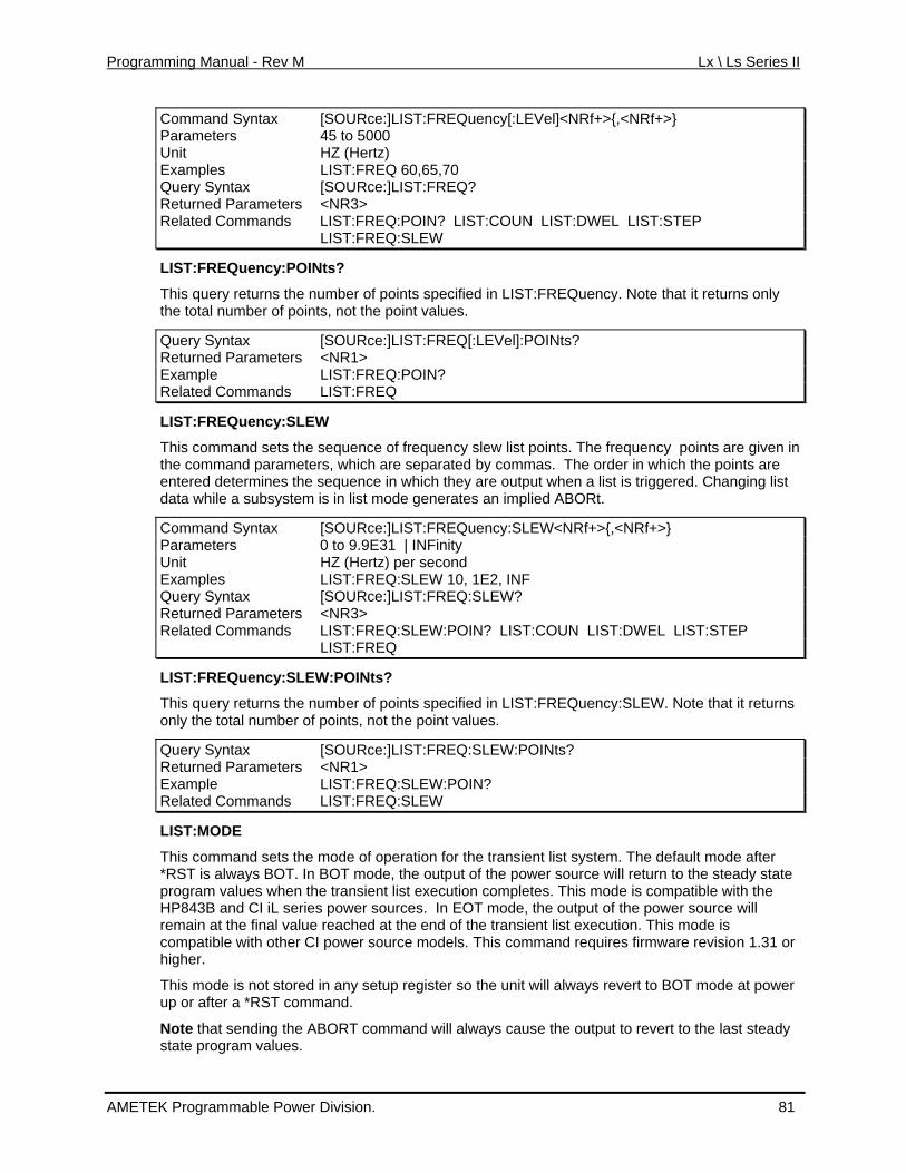
Programming Manual - Rev M Lx \ Ls Series II
Command Syntax [SOURce:]LIST:FREQuency[:LEVel]<NRf+>{,<NRf+>} Parameters 45 to 5000 Unit HZ (Hertz) Examples LIST:FREQ 60,65,70 Query Syntax [SOURce:]LIST:FREQ? Returned Parameters <NR3> Related Commands LIST:FREQ:POIN? LIST:COUN LIST:DWEL LIST:STEP LIST:FREQ:SLEW
LIST:FREQuency:POINts?
This query returns the number of points specified in LIST:FREQuency. Note that it returns only the total number of points, not the point values.
Query Syntax [SOURce:]LIST:FREQ[:LEVel]:POINts? Returned Paramete <NR1> rs Example LIST:FREQ:POIN? Related Commands LIST:FREQ
LIST:FREQuen cy:SLEW
ts are given in
equence in which they are output when a list is triggered. Changing list
Quency:SLEW<NRf+>{,<NRf+>}
This command sets the sequence of frequency slew list points. The frequency pointhe command parameters, which are separated by commas. The order in which the points are entered determines the sdata while a subsystem is in list mode generates an implied ABORt.
Command Syntax [SOURce:]LIST:FREParameters 0 to 9.9E31 | INFinity Unit HZ (Hertz) per second Examples LIST:FREQ:SLEW 10, 1E2, INF Query Syntax [SOURce:]L FREQ:SLEWIST: ? Returned Parameters <NR3> Related Commands LIST:FREQ:SLEW:POIN? LIST:COUN LIST:DWEL LIST:STEP LIST:FREQ
LIST:FREQuency:SLEW:POINts?
This query returns the number of points specified in LIST:FREQuency:SLEW. Note that it returnsonly the total number of points, not the point value
s.
Query Syntax ? [SOURce:]LIST:FREQ:SLEW:POINtsReturned Parameters <NR1> Example LIST:FREQ:SLEW:POIN? Related Commands LIST:FREQ:SLEW
LIST:MODE
This *RST is always BOT. In BOT mode, the output of the power source will return to the steady state
and requires firmware revision 1.31 or higher.
er
Note that sending the ABORT command will always cause the output to revert to the last steady state program values.
command sets the mode of operation for the transient list system. The default mode after
program values when the transient list execution completes. This mode is compatible with theHP843B and CI iL series power sources. In EOT mode, the output of the power source will remain at the final value reached at the end of the transient list execution. This mode is compatible with other CI power source models. This comm
This mode is not stored in any setup register so the unit will always revert to BOT mode at powup or after a *RST command.
AMETEK Programmable Power Division. 81
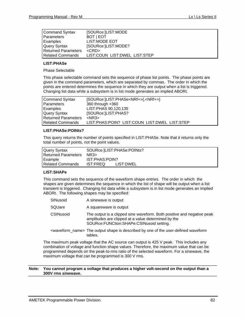
Programming Manual - Rev M Lx \ Ls Series II
Command Syntax [SOURce:]LIST:MODE Parameters BOT | EOT Examples LIST:MODE EOT Query Syntax [SOURce:]LIST:MODE? Returned Parameters <CRD> Related Commands LIST:COUN LIST:DWEL LIST:STEP
LIST:PHASe
Phase Selectable
This phase selectable command sets the sequence of phase list points. The phase points are commas. The order in which the
r e sequence in which they are output when a list is triggered. es an implied ABORt.
given in the command parameters, which are separated bypoints are entered dete mines thChanging list data while a subsystem is in list mode generat
Command Syntax [SOURce:]LIST:PHASe<NRf+>{,<NRf+>} Parameters 360 through +360 Examples LIST:PHAS 90,120,135 Query Syntax [SOURce:]LIST:PHAS? Returned Parameters <NR3> Related Commands LIST:PHAS:POIN? LIST:COUN LIST:DWEL LIST:STEP
LIST:PHASe:POINts?
This query returns the number of points specified in LIST:PHASe. Note that it returns only the
HASe:POINts?
total number of points, not the point values.
Query Syntax SOURce:]LIST:PReturned P NR3> arameters Example IST:PHAS:POIN? Related Commands IST:FREQ LIST:DWEL
LIST:SHAPe
This command sets the sequence of the waveform shape entries. The order in which the
oth positive and negative peak d by the ng.
utput shape is described by one of the user-defined waveform
V peak. This includes any nd function shape values. Therefore, the maximum value that can be the peak-to-rms ratio of the selected waveform. For a sinewave, the
Note: You cannot program a voltage that produces a higher volt-second on the output than a
shapes are given determines the sequence in which the list of shape will be output when a list transient is triggered. Changing list data while a subsystem is in list mode generates an implied ABORt. The following shapes may be specified:
SINusoid A sinewave is output
SQUare A squarewave is output
CSINusoid The output is a clipped sine waveform. Bamplitudes are clipped at a value determineSOURce:FUNCtion:SHAPe:CSINusoid setti
<waveform_name> The otables.
The maximum peak voltage that the AC source can output is 425combination of voltage aprogrammed depends onmaximum voltage that can be programmed is 300 V rms.
300V rms sinewave.
AMETEK Programmable Power Division. 82
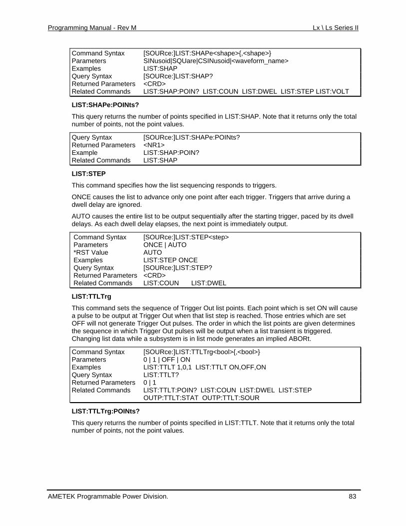
Programming Manual - Rev M Lx \ Ls Series II
Command Syn [SOURce:]LIST:SHAPe<shape>{,<tax shape>} Parameters SINusoid|SQUare|CSINusoid|<waveform_name> Examples LIST:SHAP Query Syntax [SOURce:]LIST:SHAP? Returned Parameters <CRD> Related Commands LIST:SHAP:POIN? LIST:COUN LIST:DWEL LIST:STEP LIST:VOLT
LIST:SHAPe:POINts?
This query returns the number of points specified in LIST:SHAP. Note that it returns only the total number of points, not the point values.
Query Syntax [SOURce:]LIST:SHAPe:POINts? Returned Parameters <NR1> Example LIST:SHAP:POIN? Related Commands LIST:SHAP
LIST:STEP
This command specifies how the list sequencing responds to triggers.
ONCE causes the list to advance only one point after each trigger. Triggers that arrive during a red.
lly after the starting trigger, paced by its dwell tely output.
dwell delay are igno
AUTO causes the entire list to be output sequentiadelays. As each dwell delay elapses, the next point is immedia
Command Syntax [SOURce:]LIST:STEP<step> Parameters ONCE | AUTO *RST Value AUTO Examples LIST:STEP ONCE Q [SOURce:]LIST:STEP? uery Syntax Returned Parameters <CRD> Related Commands LIST:COUN LIST:DWEL
LIST:TTLTrg
This command sets the sequence of Trigger Out list points. Each poiut when that list step is reach
nt which is set ON will cause T ed. Those entries which are set
en a list transient is triggered. ile is in list mode generates an implied ABORt.
[SOURce:]LIST:TTLTrg<bool>{,<bool>}
a pulse to be output at rigger OOFF will not generate T igger Our t pulses. The order in which the list points are given determines
h T ulses will be output whthe sequence in whic rigger Out pChanging list data wh a subsystem
Command Syntax Parameters 0 | 1 | OFF | ON Examples LIST:TTLT 1,0,1 LIST:TTLT ON,OFF,ON Query Syntax LIST:TTLT? Returned Parameters 0 | 1 Related Commands LIST:TTLT:POIN? LIST:COUN LIST:DWEL LIST:STEP OUTP:TTLT:STAT OUTP:TTLT:SOUR
LIST:TTLTrg:POINts?
LT. Note that it returns only the total This query returns the number of points specified in LIST:TTalues. number of points, not the point v
AMETEK Programmable Power Division. 83
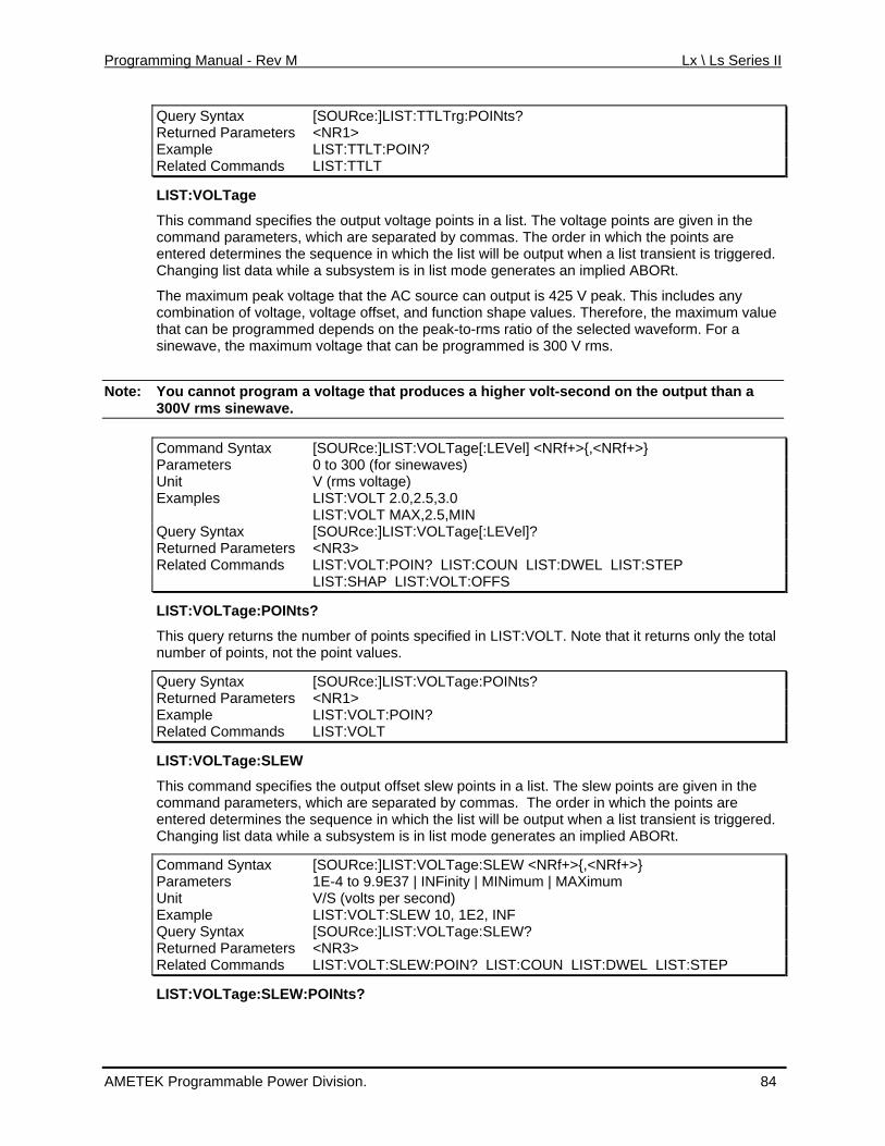
Programming Manual - Rev M Lx \ Ls Series II
Query Syntax [SOURce:]LIST:TTLTrg:POINts? Returned Parameters <NR1> Example LIST:TTLT:POIN? Related Commands LIST:TTLT
LIST:VOLTage
This command specifies the output voltage points in a list. The voltage points are given in the command parameters, which are separated by commas. The order in which the points are entered determines the sequence in which the list will be output when a list transient is triggered. Changing list data while a subsystem is in list mode generates an implied ABORt.
The maximum peak voltage that the AC source can output is 425 V peak. This includes any combination of voltage, voltage offset, and function shape values. Therefore, the maximum value that can be programmed depends on the peak-to-rms ratio of the selected waveform. For a sinewave, the maximum voltage that can be programmed is 300 V rms.
Note: You cannot program a voltage that produces a higher volt-second on the output than a 300V rms sinewave.
Command Syntax [SOURce:]LIST:VOLTage[:LEVel] <NRf+>{,<NRf+>} Parameters 0 to 300 (for sinewaves) Unit V (rms voltage) Examples LIST:VOLT 2.0,2.5,3.0 LIST:VOLT MAX,2.5,MIN Query Syntax [SOURce:]LIST:VOLTage[:LEVel]? Returned Parameters <NR3> Related Commands LIST:VOLT:POIN? LIST:COUN LIST:DWEL LIST:STEP LIST:SHAP LIST:VOLT:OFFS
LIST:VOLTage:POINts?
This query returns the number of points specified in LIST:VOLT. Note that it returns only the total number of points, not the point values.
Query Syntax [SOURce:]LIST:VOLTage:POINts? Returned Parameters <NR1> Example LIST:VOLT:POIN? Related Commands LIST:VOLT
LIST:VOLTage:SLEW
This command specifies the output offset slew points in a list. The slew points are given in the command parameters, which are separated by commas. The order in which the points are entered determines the sequence in which the list will be output when a list transient is triggered. Changing list data while a subsystem is in list mode generates an implied ABORt.
Command Syntax [SOURce:]LIST:VOLTage:SLEW <NRf+>{,<NRf+>} Parameters 1E-4 to 9.9E37 | INFinity | MINimum | MAXimum Unit V/S (volts per second) Example LIST:VOLT:SLEW 10, 1E2, INF Query Syntax [SOURce:]LIST:VOLTage:SLEW? Returned Parameters <NR3> Related Commands LIST:VOLT:SLEW:POIN? LIST:COUN LIST:DWEL LIST:STEP
LIST:VOLTage:SLEW:POINts?
AMETEK Programmable Power Division. 84
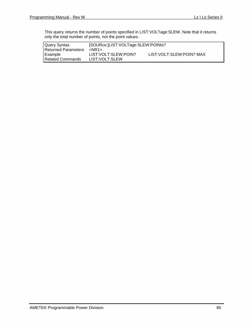
Programming Manual - Rev M Lx \ Ls Series II
This query returns the number of points specified in LIST:VOLTage:SLEW. Note that it returns e point values. only the total number of points, not th
Query Syntax [SOURce:]LIST:VOLTage:SLEW:POINts? Returned Parameters <NR1> Example LIST:VOLT:SLEW:POIN? LIST:VOLT:SLEW:POIN? MAX Related Commands LIST:VOLT:SLEW
AMETEK Programmable Power Division. 85
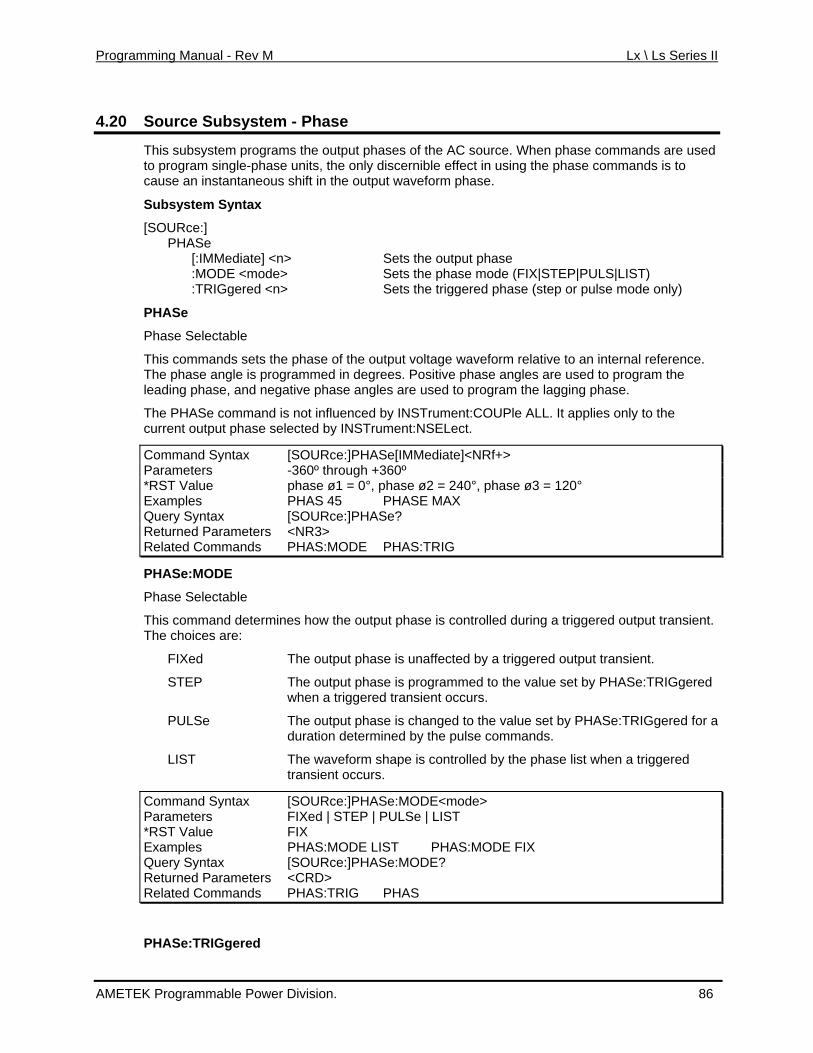
Programming Manual - Rev M Lx \ Ls Series II
4.20 Source Subsystem - Phase
This subsystem programs the output phases of the AC source. When phase commands are used to program single-phase units, the only discernible effect in using the phase commands is to cause an instantaneous shift in the output waveform phase.
Subsystem Syntax
[SOURce:] PHASe [:IMMediate] <n> Sets the output ph :MODE <mode> Sets the phase mo
ase EP|PULS|LIST)
IGgered <n> p or pulse mode only)
This commands sets the phase of the output voltage waveform relative to an internal reference. The phase angle is programmed in degrees. Positive phase angles are used to program the leading phase, and negative phase angles are used to program the lagging phase.
The PHASe command is not influenced by INSTrument:COUPle ALL. It applies only to the current output phase selected by INSTrument:NSELect.
Command Syntax [SOURce:]PHASe[IMMediate]<NRf+>
de (FIX|ST Sets the triggered phase (ste :TR
PHASe
Phase Selectable
Parameters -360º through +360º *RST Value phase ø1 = 0°, phase ø2 = 240°, phase ø3 = 120° Examples PHAS 45 PHASE MAX Query Syntax [SOURce:]PHASe? Returned Parameters <NR3> Related Commands PHAS:MODE PHAS:TRIG
PHASe:MODE
Phase Selectable
This command determines how the output phase is controlled during a triggered output transient. The choices are:
FIXed The output phase is unaffected by a triggered output transient.
STEP The output phase is programmed to the value set by PHASe:TRIGgered when a triggered transient occurs.
PULSe The output phase is changed to the value set by PHASe:TRIGgered for a duration determined by the pulse commands.
LIST The waveform shape is controlled by the phase list when a triggered transient occurs.
Command Syntax [SOURce:]PHASe:MODE<mode> Parameters FIXed | STEP | PULSe | LIST *RST Value FIX Examples PHAS:MODE LIST PHAS:MODE FIX Query Syntax [SOURce:]PHASe:MODE? Returned Parameters <CRD> Related Commands PHAS:TRIG PHAS
PHASe:TRIGgered
AMETEK Programmable Power Division. 86
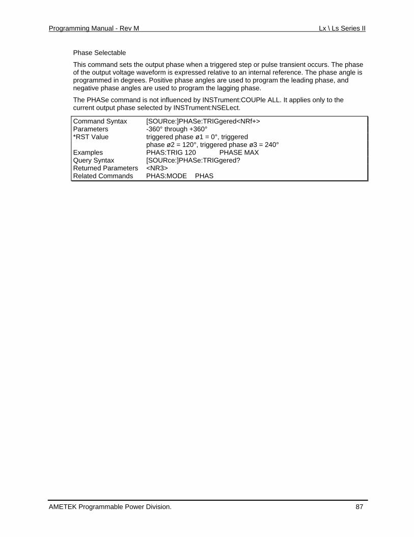
Programming Manual - Rev M Lx \ Ls Series II
Phase Selectable
e when a triggered step or pulse transient occurs. The phase is
selected by INSTrument:NSELect.
yntax [SOURce:]PHASe:TRIGgered<NRf+>
This command sets the output phasof the output voltage waveform is expressed relative to an internal reference. The phase angle programmed in degrees. Positive phase angles are used to program the leading phase, and negative phase angles are used to program the lagging phase.
The PHASe command is not influenced by INSTrument:COUPle ALL. It applies only to the current output phase
Command SParameters -360° through +360° *RST Value triggered phase ø1 = 0°, triggered phase ø2 = 120°, triggered phase ø3 = 240° Examples PHAS:TRIG 120 PHASE MAX Query Syntax e:TRIGgered? [SOURce:]PHASR ur d Parameterset ne <NR3> Related Commands PHAS PHAS:MODE
AMETEK Programmable Power Division. 87
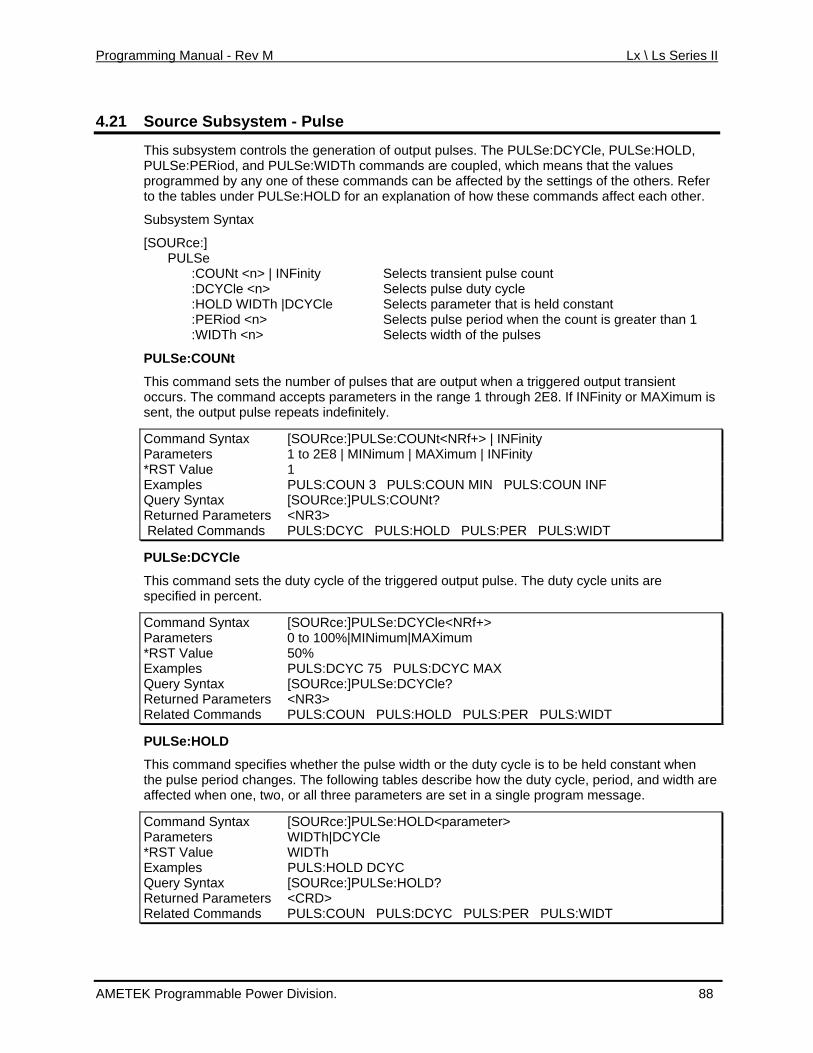
Programming Manual - Rev M Lx \ Ls Series II
4.21 SSource ubsystem - Pulse
This ubsystem controls ge OLD, PULSe:PERiod, and PULSe:WI values prog mmed b ny one thes . Refer to the tables under PULSe:HOL t each other.
Subsystem Syntax
[SOURce:] PULSe :COUNt <n> | INFinity :DCYCle <n> :HOLD IDTh |D YCle :PERiod <n> ter than 1 :WIDTh <n>
PULSe:COUNt
This command sets the number of pulses thatoccurs. The command ac INFinity or MAXimum is sent, the output pulse repeats indefinitely.
:]PULSe:COUNt<NRf+> | INFinity
s the neration of output pulses. The PULSe:DCYCle, PULSe:HDTh commands are coupled, which means that the
ra y a of e commands can be affected by the settings of the othersD for an explanation of how these commands affec
Selects transient pulse count Selects pulse duty cycle
W C Selects parameter that is held constant Selects pulse period when the count is grea
Selects width of the pulses
are output when a triggered output transient cepts parameters in the range 1 through 2E8. If
Command Syntax [SOURceParameters | MINimum | MAXimum | INFinity 1 to 2E8 *RST Value 1 Examples P LS:C INF U OUN 3 PULS:COUN MIN PULS:COUNQuery Syntax [ URSO ce:]PULS:COUNt? Returned Parameters R3><N Related Commands PULS:DCYC PULS:HOLD PULS:PER PULS:WIDT
PULSe:DCYCle
This mmand ets the d y cyc are specified in percent.
Command Syntax UR
co s ut le of the triggered output pulse. The duty cycle units
[SO ce:]PULSe:DCYCle<NRf+> Parameters 0 o 10t 0%|MINimum|MAXimum *RST Value 50% Examples PULS:DCYC 75 PULS:DCYC MAX Query Syntax [SOURce:]PULSe:DCYCle? Returned Parameters <NR3> Related Commands PULS:COUN PULS:HOLD PULS:PER PULS:WIDT
PULSe:HOLD
This command specifies whether the pulse width or the duty cycle is to be held constant when the duty cycle, period, and width are
ge.
ommand Syntax
the pulse period changes. The following tables describe howaffected when one, two, or all three parameters are set in a single program messa
C [SOURce:]PULSe:HOLD<parameter> Parameters WIDTh|DCYCle *RST Value WIDTh Examples PULS:HOLD DCYC Query Syntax [SOURce:]PULSe:HOLD? Returned Parameters <CRD> Related Commands PULS:COUN PULS:DCYC PULS:PER PULS:WIDT
AMETEK Programmable Power Division. 88
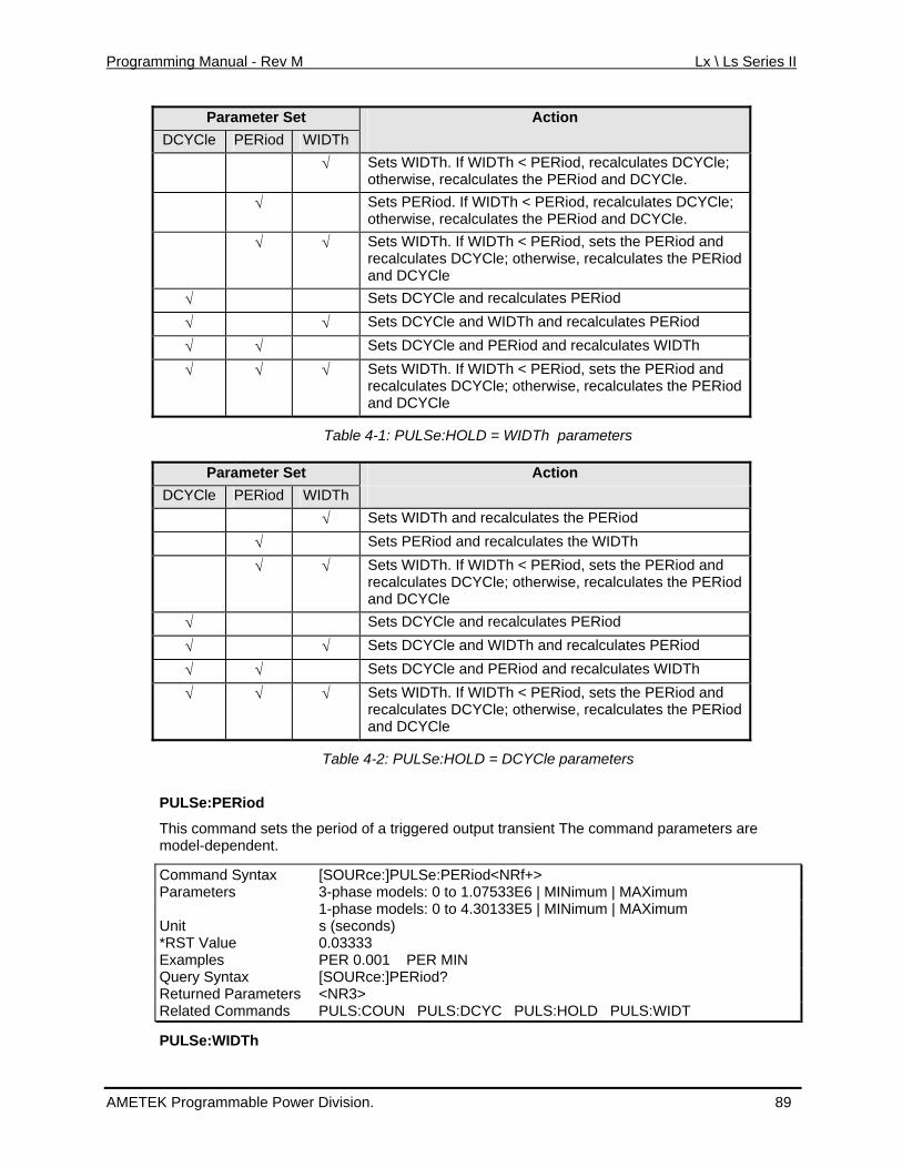
Programming Manual - Rev M Lx \ Ls Series II
Parameter Set Action DCYCle PERiod WIDTh
√ Sets WIDTh. If WIDTh < PERiod, recalculates DCYCle; otherwise, recalculates the PERiod and DCYCle.
√ Sets PERiod. If WIDTh < PERiod, recalculates DCYCle; Cle. otherwise, recalculates the PERiod and DCY
√ Sets WIDTh. If WIDTh < PERio; otherwise, recalculates the PERiod
√ Riod and d, sets the PErecalculates DCYCleand DCYCle
√ Sets DCYCle and recalculates PERiod
√ √ Sets DCYCle and WIDTh and recalculates PERiod
√ √ Sets DCYCle and PERiod and recalculates WIDTh
√ √ √ Sets WIDTh. If WIDTh < PERiod, sets the PERiod and recalculates DCYCle; otherwise, recalculates the PERiod and DCYCle
Table 4-1: PULSe:HOLD = WIDTh parameters
Parameter Set Action DCYCle PERiod WIDTh
√ Sets WIDTh and recalculates the PERiod √ Sets PERiod and recalculates the WIDTh √ √ Sets WIDTh. If WIDTh < PERiod, sets the PERiod and
recalculates DCYCle; otherwise, recalculates the PERiod and DCYCle
√ Sets DCYCle and recalculates PERiod
√ √ Sets DCYCle and WIDTh and recalculates PERiod
√ √ Sets DCYCle and PERiod and recalculates WIDTh
√ √ √ Sets WIDTh. If WIDTh < PERiod, sets the PERiod and recalculates DCYCle; otherwise, recalculates the PERiod and DCYCle
Table 4-2: PULSe:HOLD = DCYCle parameters
PULSe:PERiod
This command sets the period of a triggered output transient The command parameters are model-dependent.
Command Syntax [SOURce:]PULSe:PERiod<NRf+> Parameters 3-phase models: 0 to 1.07533E6 | MINimum | MAXimum 1-phase models: 0 to 4.30133E5 | MINimum | MAXimum Unit s (seconds) *RST Value 0.03333 Examples PER 0.001 PER MIN Query Syntax [SOURce:]PERiod? Returned Parameters <NR3> Related Commands PULS:COUN PULS:DCYC PULS:HOLD PULS:WIDT
PULSe:WIDTh
AMETEK Programmable Power Division. 89
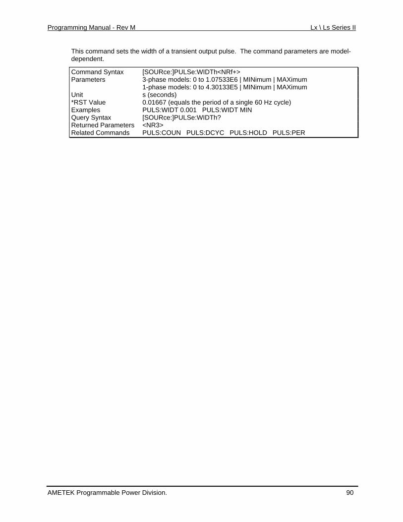
Programming Manual - Rev M Lx \ Ls Series II
This command sets the width of a transient output pulse. The command parameters are model-dependent.
Command Syntax [SOURce:]PULSe:WIDTh<NRf+> Parameters 3-phase models: 0 to 1.07533E6 | MINimum | MAXimum 1-phase models: 0 to 4.30133E5 | MINimum | MAXimum Unit s (seconds) *RST Value 0.01667 (equals the period of a single 60 Hz cycle) Examples PULS:WIDT 0.001 PULS:WIDT MIN Query Syntax [SOURce:]PULSe:WIDTh? Returned Parameters <NR3> Related Commands PULS:COUN PULS:DCYC PULS:HOLD PULS:PER
AMETEK Programmable Power Division. 90
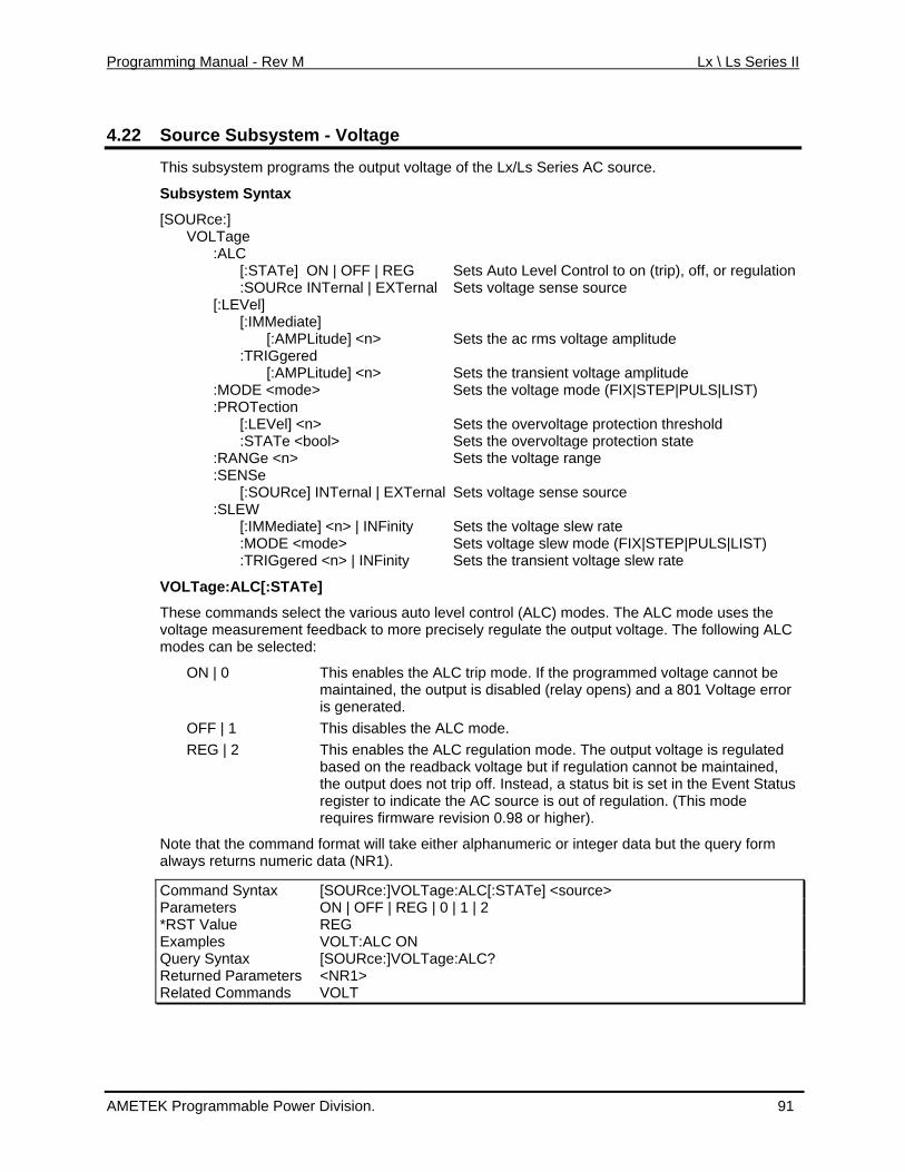
Programming Manual - Rev M Lx \ Ls Series II
4.22 Voltage Source Subsystem -
This subsystem programs the output voltage of the Lx/Ls Series AC source.
Sub yntax
[SOURce:] VOLTage :ALC
IN el]
ltage amplitude
i Sets the transient voltage amplitude Sets the voltage mode (FIX|STEP|PULS|LIST)
:PROTection
NSe [:SOURce] INTernal | EXTernal Sets voltage sense source
rious auto level control (ALC) modes. The ALC mode uses the voltage measurement feedback to more precisely regulate the output voltage. The following ALC
This enables the ALC trip mode. If the programmed voltage cannot be maintained, the output is disabled (relay opens) and a 801 Voltage error
de. ALC regulation mode. The output voltage is regulated
e re but if regulation cannot be maintained, ad, a status bit is set in the Event Status
n. (This mode
m ata but the query form always returns numeric data (NR1).
Command Syntax [SOURce:]VOLTage:ALC[:STATe] <source>
system S
[:STATe] ON | OFF | REG Sets Auto Level Control to on (trip), off, or regulation :SOURce Ternal | EXTernal Sets voltage sense source [:LEV [:IMMediate] [:AMPLitude] <n> Sets the ac rms vo :TRIGgered [:AMPL tude] <n> :MODE <mode> [:LEVel] <n> Sets the overvoltage protection threshold :STATe <bool> Sets the overvoltage protection state :RANGe <n> Sets the voltage range :SE :SLEW [:IMMediate] <n> | INFinity Sets the voltage slew rate :MODE <mode> Sets voltage slew mode (FIX|STEP|PULS|LIST) :TRIGgered <n> | INFinity Sets the transient voltage slew rate
VOLTage:ALC[:STATe]
These commands select the va
modes can be selected:
ON | 0
is generated. OFF | 1 This disables the ALC moREG | 2 This enables the
based on th adback voltage stethe output does not trip off. In
register to indicate the AC source is out of regulatiofirmware revision 0.98 or higher). requires
Note that the command format will take either alphanu eric or integer d
Parameters ON | OFF | REG | 0 | 1 | 2 *RST Value REG Examples VOLT:ALC ON Query Syntax [SOURce:]VOLTage:ALC? Returned Parameters <NR1> Related Commands VOLT
AMETEK Programmable Power Division. 91
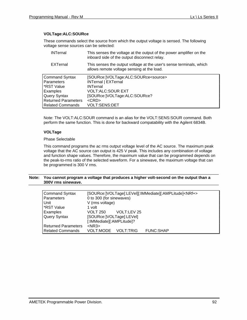
Programming Manual - Rev M Lx \ Ls Series II
VOLTage:ALC:SOURce
select the source from which the output voltage is sensed. The following
es the voltage at the output of the power amplifier on the
These commands voltage sense sources can be selected:
INTernal This sensinboard side of the output disconnect relay.
EXTernal This senses the output voltage at the user's sense terminals, which allows remote voltage sensing at the load.
Command Syntax [SOURce:]VOLTage:ALC:SOURce<source> Parameters INTernal | EXTernal *RST Value INTernal Examples VOLT:ALC:SOUR EXT Query Syntax [SOURce:]VOLTage:ALC:SOURce? Returned Paramete <CRD> rs Related Com VOLT:SENS:DET mands
Note: The VO OUR coLT:ALC:S ENS:SOUR command. Both ilent 6834B.
grams the ac rms output voltage level of the AC source. The maximum peak peak. This includes any combination of voltage
values. Therefore, the maximum value that can be programmed depends on
Note: You cannot program a v
mmand is an alias for the VOLT:Sperform the same function. This is done for backward compatability with the Ag
VOLTage
Phase Selectable
This command provoltage that the AC source can output is 425 V and function shapethe peak-to-rms ratio of the selected waveform. For a sinewave, the maximum voltage that can be programmed is 300 V rms.
oltage that produces a higher volt-second on the output than a 300V rms sinewave.
Command Syntax [SOURce:]VOLTage[:LEVel][:IMMediate][:AMPLitude]<NRf+> Parameters 0 to 300 (for sinewaves) Unit V (rms voltage) *RST Value 1 volt Examples VOLT:LEV 25 VOLT 250 Query Syntax [SOURce:]VOLTage[:LEVel] [:IMMediate][:AMPLitude]? Returned Par <NRameters 3> Related Co VOLT:MODE VOLT:TRIG FUNC:SHAmmands P
AMETEK Programmable Power Division. 92
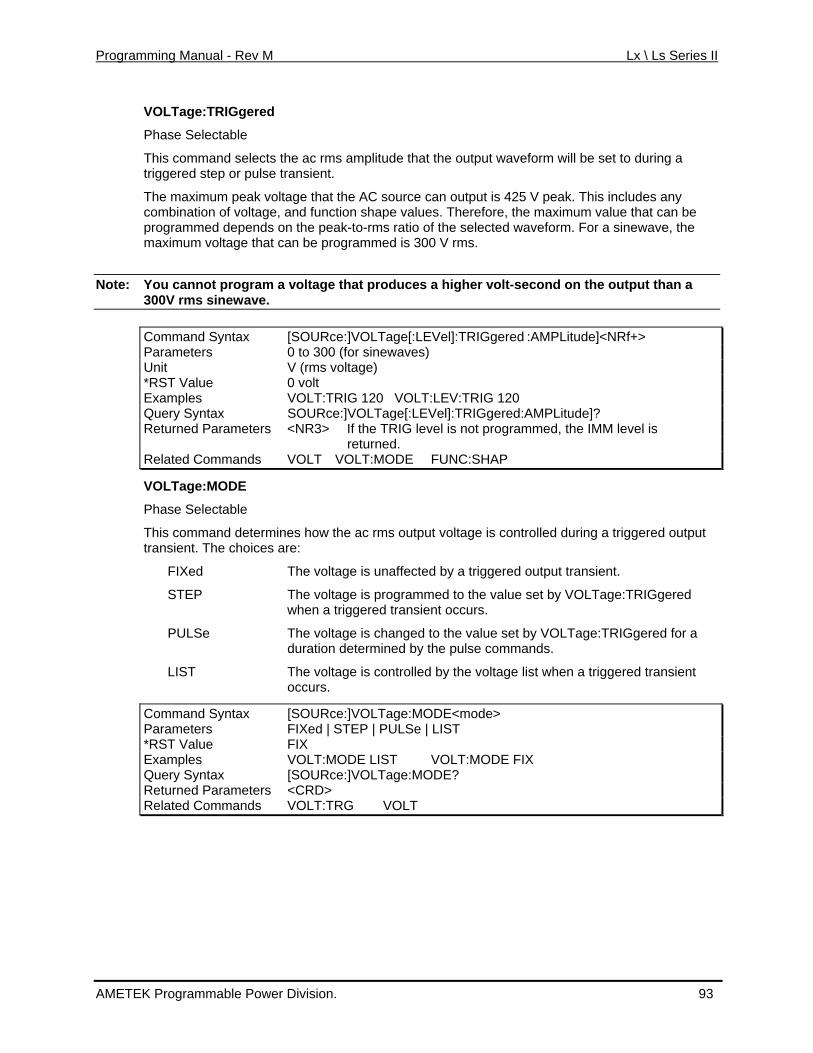
Programming Manual - Rev M Lx \ Ls Series II
VOLTage:TRIGgered
Phase Selectable
This command selects the ac rms amplitude that the output waveform will be set to during a triggered step or pulse transient.
The maximum peak voltage that the AC source can output is 425 V peak. This includes any combination of voltage, and function shape values. Therefore, the maximum value that can be programmed depends on the peak-to-rms ratio of the selected waveform. For a sinewave, the maximum voltage that can be programmed is 300 V rms.
Note: uces a higher volt-second on the output than a You cannot program a voltage that prod300V rms sinewave.
Command Syn [SOURce:]VOLTage[:LEVel]:TRIGgered :AMtax PLitude]<NRf+> Parameters 0 to 300 (for sinewaves) Unit V (rms voltage) *RST Value 0 volt Examples VOLT:TRIG 120 VOLT:LEV:TRIG 120 Query Syntax SOURce:]VOLTage[:LEVel]:TRIGgered:AMPLitude]? Returned Parameters <NR3> If the TRIG level is not programmed, the IMM level is
returned. Related Commands VOLT VOLT:MODE FUNC:SHAP
VOLTage:MODE
Phase Selectable
This command determines how the ac rms output voltage is controlled during a triggered output
The voltage is programmed to the value set by VOLTage:TRIGgered
or a
e list when a triggered transient
ntax
transient. The choices are:
FIXed The voltage is unaffected by a triggered output transient.
STEP when a triggered transient occurs.
PULSe The voltage is changed to the value set by VOLTage:TRIGgered fduration determined by the pulse commands.
LIST The voltage is controlled by the voltagoccurs.
Command [SOURce:]VOLTage:MODE<mode> SyParameters FIXed | STEP | PULSe | LIST *RST Value FIX Examples VOLT:MODE LIST VOLT:MODE FIX Query Syntax [SOUR e age:MODE?c :]VOLT Returned Parameters <CRD> Related Commands VOLT:TRG VOLT
AMETEK Programmable Power Division. 93
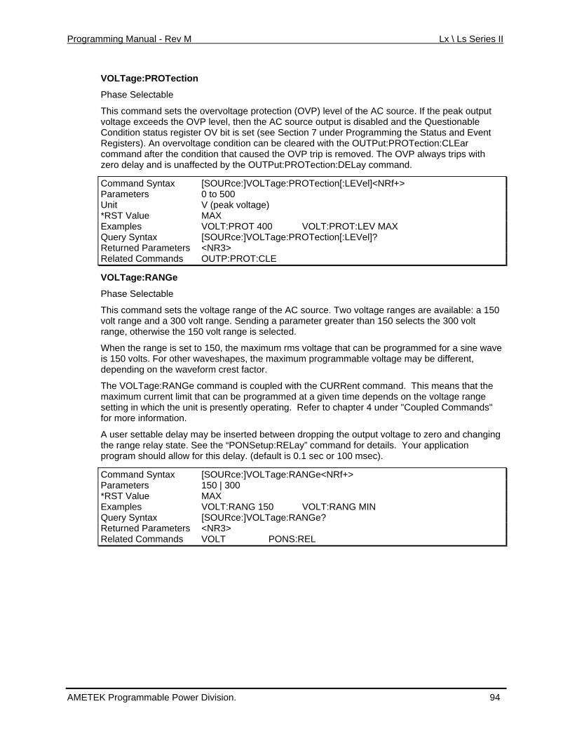
Programming Manual - Rev M Lx \ Ls Series II
VOLTage:PROTection
Phase Selectable
This command sets the overvoltage protection (OVP) level of the AC source. If the peak output volt ds the OV Condition status registe ing the Status and Event Reg overvoltacom the cond zero delay and is unaffe mand.
age excee P level, then the AC source output is disabled and the Questionabler OV bit is set (see Section 7 under Programm
isters). An ge condition can be cleared with the OUTPut:PROTection:CLEar mand after ition that caused the OVP trip is removed. The OVP always trips with
cted by the OUTPut:PROTection:DELay com
Command Syntax [SOURce:]VOLTage:PROTection[:LEVel]<NRf+> Parameters 0 to 500 Unit V (peak voltage) *RST Value MAX Examples VOLT:PROT 400 VOLT:PROT:LEV MAX Query Syntax [SOURce:]VOLTage:PROTection[:LEVel]? Returned Parameters <NR3> Related Commands OUTP:PROT:CLE
VOLTage:RANGe
Phase Selectable
This command setvolt range and a 30
s the voltage range of the AC source. Two voltage ranges are available: a 150 0 volt range. Sending a parameter greater than 150 selects the 300 volt
eans that the n the voltage range
efer to chapter 4 under "Coupled Commands" mation.
and changing NSetup:RELay” command for details. Your application
0
Command Syntax [SOURce:]VOLTage:RANGe<NRf+>
range, otherwise the 150 volt range is selected.
When the range is set to 150, the maximum rms voltage that can be programmed for a sine waveis 150 volts. For other waveshapes, the maximum programmable voltage may be different, depending on the waveform crest factor.
The VOLTage:RANGe command is coupled with the CURRent command. This mmaximum current limit that can be programmed at a given time depends osetting in which the unit is presently operating. Rfor more infor
A user settable delay may be inserted between dropping the output voltage to zero the range relay state. See the “POprogram should allow for this delay. (default is .1 sec or 100 msec).
Parameters 150 | 300 *RST Value MAX Examples VOLT:RANG 150 VOLT:RANG MIN Query Syntax [SOURce:]VOLTage:RANGe? Returned Parameters <NR3> Related Commands VOLT PONS:REL
AMETEK Programmable Power Division. 94
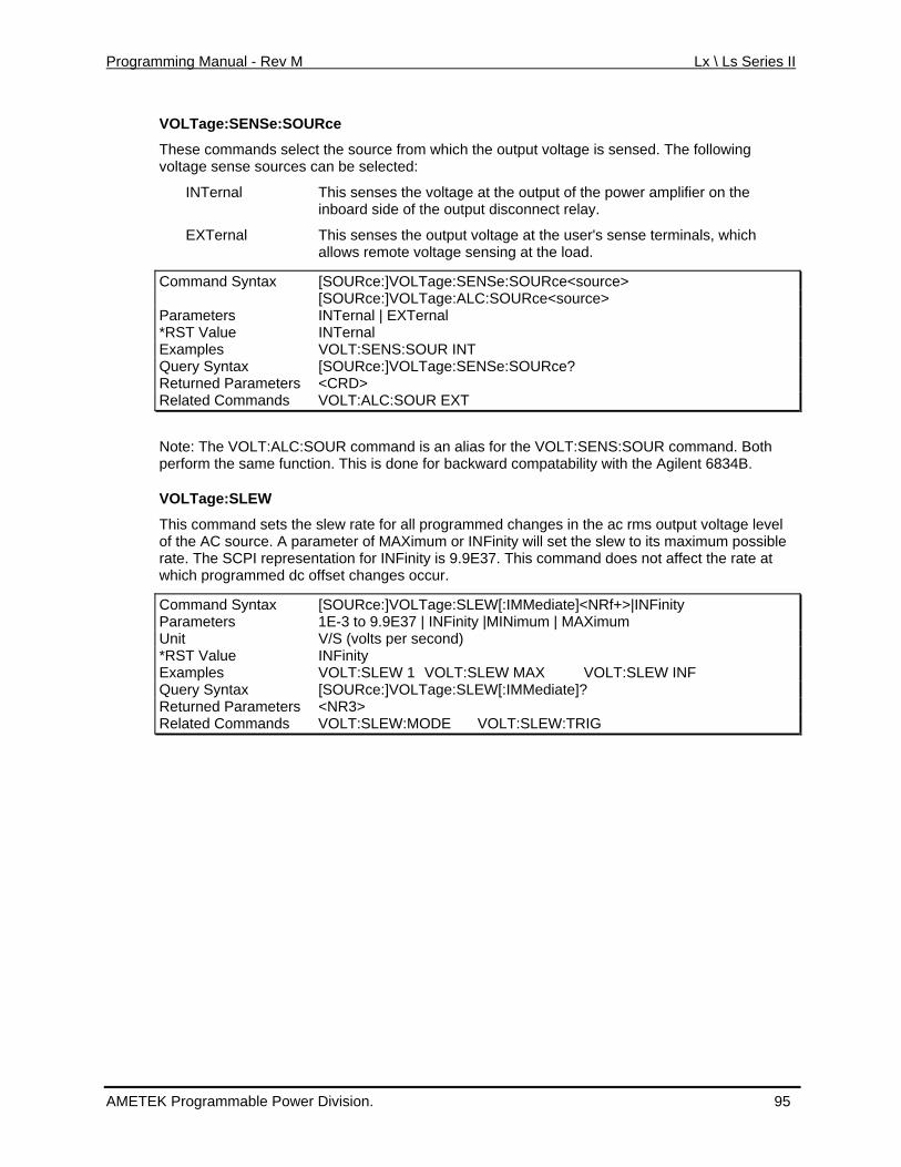
Programming Manual - Rev M Lx \ Ls Series II
VOLTage:SENSe:SOURce
select the source from which the output voltage is sensed. The following
s the voltage at the output of the power amplifier on the
al terminals, which
Command Syntax >
These commands voltage sense sources can be selected:
INTernal This senseinboard side of the output disconnect relay.
EXTern This senses the output voltage at the user's senseallows remote voltage sensing at the load.
[SOURce:]VOLTage:SENSe:SOURce<source [SOURce:]VOLTage:ALC:SOURce<source> Parameters INTernal | EXTernal *RST Value INTernal Exa mples VOLT:SENS:SOUR INT Query Syntax ge:SENSe:SOURce? [SOURce:]VOLTaReturned Paramete <CRD> rs Related Com VOLT:ALC:SOUR EXT mands
Note: The V OUR command is an alias f VOLT:SENS:SOUR commOLT:ALC:S or the and. Both bility with the Agilent 6834B.
te for all programmed changes in the ac rms output voltage level parameter of MAXimum or INFinity will set the slew to its maximum possible
resentation for INFinity is 9.9E37. This command does not affect the rate at
perform the same function. This is done for backward compata
VOLTage:SLEW
This command sets the slew raof the AC source. Arate. The SCPI repwhich programmed dc offset changes occur.
Command Syntax [SOURce:]VOLTage:SLEW[:IMMediate]<NRf+>|INFinity Parameters 1E-3 to 9.9E37 | INFinity |MINimum | MAXimum Unit V/S (volts per second) *RST Value INFinity Exam VOLT:SLEW 1 VOLT:Sples LEW MAX VOLT:SLEW INF Query Syntax [SOURce :]VOLTage:SLEW[:IMMediate]? Returned P <NR3> arameters Related Commands VOLT:SLEW:MODE VOLT:SLEW:TRIG
AMETEK Programmable Power Division. 95
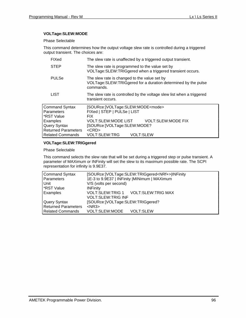
Programming Manual - Rev M Lx \ Ls Series II
VOLTage:SLEW:MODE
Phase Selectable
This command determines how the output voltage slew rate is controlled during a triggered output transient. The choices are:
FIXed The slew rate is unaffected by a triggered output transient.
STEP The slew rate is programmed to the value set by OLTage :TRIGge trigg nt occurs.
y VOLTage:SLEW:TRIGgered for a duration determined by the pulse commands.
The slew rate istransient occurs
om a [SOURce:]VOLT
V :SLEW red when a ered transie
PULSe The slew rate is changed to the value set b
LIST controlled by the voltage slew list when a triggered .
C m nd Syntax age:SLEW:MODE<mode> Parameters ULSe | LIST FIXed | STEP | P*RST Value FIX Examples VOLT:SLEW:MODE LIST VOLT:SLEW:MODE FIX Query Syntax [SOURce:]VOLTage:SLEW:MODE? Returned Parameters <CRD> R at Command G VOLT:SLEW el ed s VOLT:SLEW:TR
VOLTage:SLEW:TRIGgered
slew rate that will be set during a triggered step or pulse transient. A Finity will set the slew to its maximum possible rate. The SCPI
pr se ati n f 9.9E37.
Phase Selectable
This command selects theparameter of MAXimum or INre e nt o or infinity is
Command Syntax [SOURce:]VOLTage:SLEW:TRIGgered<NRf+>|INFinity Parameters 1E-3 to 9.9E37 | INFinity |MINimum | MAXimum Unit V/S (volts per second) *RST Value INFinity Examples VOLT:SLEW:TRIG 1 VOLT:SLEW:TRIG MAX VOLT:SLEW:TRIG INF Query Syntax [SOURce:]VOLTage:SLEW:TRIGgered? Returned Parameters <NR3> Related Commands VOLT:SLEW:MODE VOLT:SLEW
AMETEK Programmable Power Division. 96
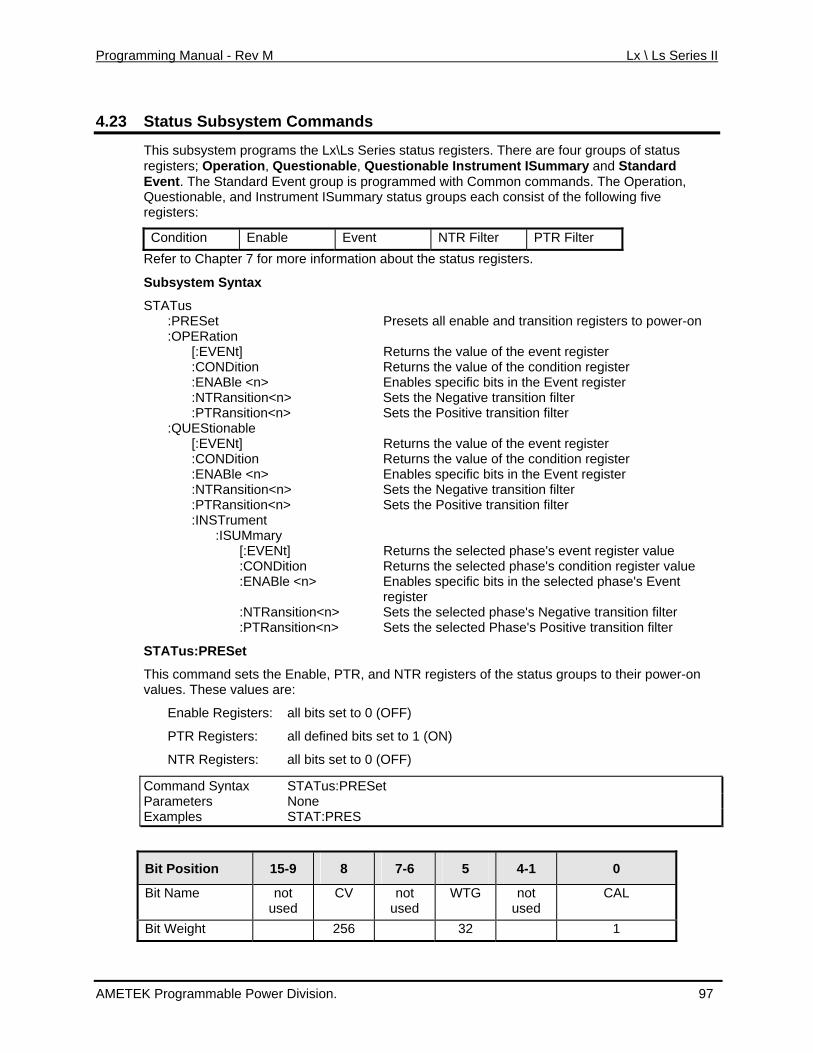
Programming Manual - Rev M Lx \ Ls Series II
4.23 system Commands Status Sub
This su system programs the Lx\Ls Serieregisters; Operation, Questionable, Que
b s status registers. There are four groups of status stionable Instrument ISummary and Standard
t. The Standard Event group is programmed with Common commands. The Operation, Questionable, and wing five registers:
Event NTR Filter PTR Filter
EvenInstrument ISummary status groups each consist of the follo
Condition EnableRefer to Chapter 7 for more information about the status registers.
Subsystem Syntax
STATus :PRESet Presets all enable and transition registers to power-on
ter f the condition register
nt register
Sets the Positive transition filter
gister le <n> its in the Event register
nsition filter
y Returns the selected phase's event register value
lue
ts the selected Phase's Positive transition filter
sets the , and NTR registers of the status groups to their power-on
:OPERation [:EVENt] Returns the value of the event regis :CONDition Returns the value o :ENABle <n> Enables specific bits in the Eve :NTRansition<n> Sets the Negative transition filter :PTRansition<n> :QUEStionable [:EVENt] Returns the value of the event register :CONDition Returns the value of the condition re :ENAB Enables specific b
ts the Negative transition filter :NTRansition<n> Se :PTRansition<n> Sets the Positive tra :INSTrument :ISUMmar [:EVENt] :CONDition Returns the selected phase's condition register va :ENABle <n> Enables specific bits in the selected phase's Event
register :NTRansition<n> Sets the selected phase's Negative transition filter :PTRansition<n> Se
STATus:PRESet
This command Enable, PTRvalues. These values are:
Enable Registers: all bits set to 0 (OFF)
PTR Registers: all defined bits set to 1 (ON)
NTR Registers: all bits set to 0 (OFF)
Command Syntax STATus:PRESet Parameters None Examples STAT:PRES
B Position it 15-9 8 7-6 5 4-1 0
Bit CV not WTG not CAL Name not used used used
Bit Weight 256 32 1
AMETEK Programmable Power Division. 97
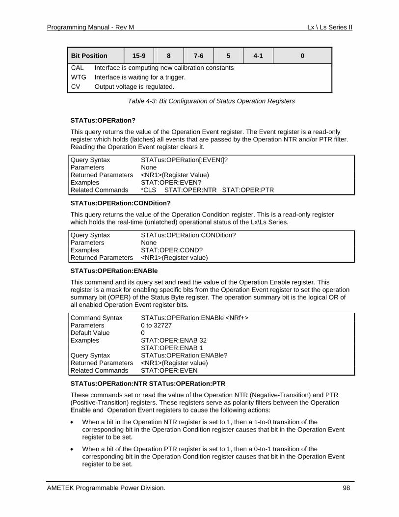
Programming Manual - Rev M Lx \ Ls Series II
B Position it 15-9 8 7-6 5 4-1 0
CAL Interface is computing new calibration constants G Interface is waiting for a trigger.
OutpWTCV ut voltage is regulated.
Table 4-3: Bit Configuration of Status Operation Registers
STATus:OPERation?
vent register is a read-only filter.
Operation E r clears it.
This query returns the value of the Operation Event register. The Eregister which holds (latches) all events that are passed by the Operation NTR and/or PTRReading the vent registe
Query Synt STATus:OPERation[:EVENt]? ax Parameters None Returned Parameters <NR1>(Register Value) Examples STAT:OPER:EVEN? Related Commands *CLS STAT:OPER:NTR STAT:OPER:PTR
STATus:OPERation:CONDition?
ondition register. This is a read-only register ich holds the real-time (unlatched) operational status of the Lx\Ls Series.
uery x STA :OPERati NDitio
This query returns the value of the Operation Cwh
Q Synta Tus on:CO n? Parameters None Example STAT:OPER:COND? sReturned Parameters <NR1>(Register value)
STATus:OPERation:ENABle
This mand and its q eration Enable register. This regi a mask for en n Event register to set the operation summary bit (OPER) of the Status Byte register. The operation summary bit is the logical OR of all e Operation E
Command Syntax
com uery set and read the value of the Opster is abling specific bits from the Operatio
nabled vent register bits.
STATus:OPERation:ENABle <NRf+> Parameters 0 to 32727 Default Value 0 Examples STAT:OPER:ENAB 32 STAT:OPER:ENAB 1 Query Syntax ? STATus:OPERation:ENABleReturned Parameters <NR1>(Register value) Related Commands STAT:OPER:EVEN
STATus:OPERation:NTR STATus:OPERation:PTR
These commands set or read the value of the Operation NTR (Negative-Transition) and PTR (Positive-Transition) registers. These registers serve as polarity filters between the Operation
corresponding bit in the Operation Condition register causes that bit in the Operation Event register to be set.
• When a bit of the Operation PTR register is set to 1, then a 0-to-1 transition of the corresponding bit in the Operation Condition register causes that bit in the Operation Event register to be set.
Enable and Operation Event registers to cause the following actions:
• When a bit in the Operation NTR register is set to 1, then a 1-to-0 transition of the
AMETEK Programmable Power Division. 98
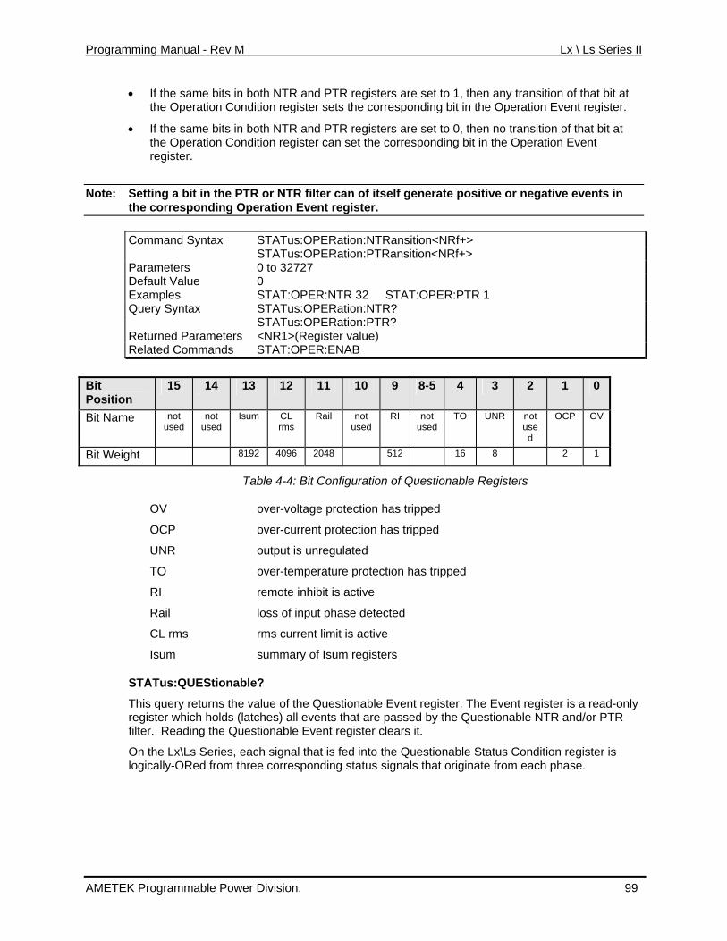
Programming Manual - Rev M Lx \ Ls Series II
• If the same bits in both NTR and PTR registers are set to 1, then any transition of that bit at e corresponding bit in the Operation Event register.
0, then no transition of that bit at Operation Event
Note:
the Operation Condition register sets th
If the same bits in both NTR and PTR registers are set to• the Operation Condition register can set the corresponding bit in the register.
Setting a bit in the PTR or NTR filter can of itself generate positive or negative events in the corresponding Operation Event register.
Command Syntax STATus:OPERation:NTRansition<NRf+> STATus:OPERation:PTRansition<NRf+> Parameters 0 to 32727 Default Value 0 Examples STAT:OPER:NTR 32 STAT:OPER:PTR 1 Query Syntax STATus:OPERation:NTR? STATus:OPERation:PTR? Returned Parameters <NR1>(Register value) Related Commands STAT:OPER:ENAB
Bit Position
15 14 13 12 11 10 9 8-5 4 3 2 1 0
Bit Nam
not used
OCP OV e not used u
CL rms
Rail not used
RI notused
not Isum TO UNR sed
Bit Weig 19 512 16 8 2 1 ht 8 2 4096 2048
Table 4-4: Bit Configuration of Questionable Registers
te inhibit is active
urrent limit is active
STATus:QUEStionable?
ly regfilter. Reading the Questionable Event register clears it.
On the Lx\Ls Series, each signal that is fed into the Questionable Status Condition register is
OV over-voltage protection has tripped
OCP over-current protection has tripped
UNR output is unregulated
TO over-temperature protection has tripped
RI remo
Rail loss of input phase detected
CL rms rms c
Isum summary of Isum registers
This query returns the value of the Questionable Event register. The Event register is a read-onister which holds (latches) all events that are passed by the Questionable NTR and/or PTR
logically-ORed from three corresponding status signals that originate from each phase.
AMETEK Programmable Power Division. 99
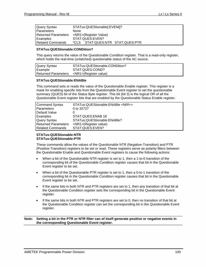
Programming Manual - Rev M Lx \ Ls Series II
Query Syntax STATus:QUEStionable[:EVENt]? Parameters None Returned Pa <NR1>(Regrameters ister Value) Examples STAT:QUES:EVEN? Related Co *CLS STAT:QUES:NTR STAT:QUES:PTR mmands
STATus:QUEStionable:CONDition?
This query returns the alue of the Questionable Cv ondition register. That is a read-only register, able status of the AC source.
STATus:QUEStionable:CONDition?
which holds the real-time (unlatched) question
Query Syntax Example STAT:QUES:COND? Returned Parameters <NR1>(Register value)
STAT ES bl AB
com and r the lue o Questionable Enable register. This register is a tionable Event register to set the questionable
summary ( Questionable Event register bits that are enabl
nable:ENABle <NRf+>
us:QU tiona e:EN le
Thismask for enabling specific bits from the Ques
m sets o reads va f the
QUES) bit of the Status Byte register. This bit (bit 3) is the logical OR of all theed by the Questionable Status Enable register.
Command Syntax STATus:QUEStioParameters 0 to 32727 Default Value 0 Examples STAT:QUES:ENAB 18 Query Syntax STATus:QUEStionable:ENABle? Returned Parameters <NR1>(Register value) Related Commands STAT:QUES:EVEN?
STATus:QUEStionable:NTR STATus:QUEStionable:PTR
These commands allow the values of the Questionab(Positive-Transition) registers to be set or read. Thes
le NTR (Negative-Transition) and PTR e registers serve as polarity filters between
nable and Questionable Event registers to cause the following actions:
able
uestionable
o are set to 1, then any transition of that bit at Questionable Event
If the same bits in both NTR and PTR registers are set to 0, then no transition of that bit at the Questionable Condition register can set the corresponding bit in the Questionable Event register.
Note: Setting a bit in the PTR or NTR filter can of itself generate positive or negative events in
the Questionable E
• When a bit of the Questionable NTR register is set to 1, then a 1-to-0 transition of the corresponding bit of the Questionable Condition register causes that bit in the QuestionEvent register to be set.
• When a bit of the Questionable PTR register is set to 1, then a 0-to-1 transition of thecorresponding bit in the Questionable Condition register causes that bit in the QEvent register to be set.
• If the same bits in b th NTR and PTR registersthe Questionable Condition register sets the corresponding bit in theregister.
•
the corresponding Questionable Event register.
AMETEK Programmable Power Division. 100
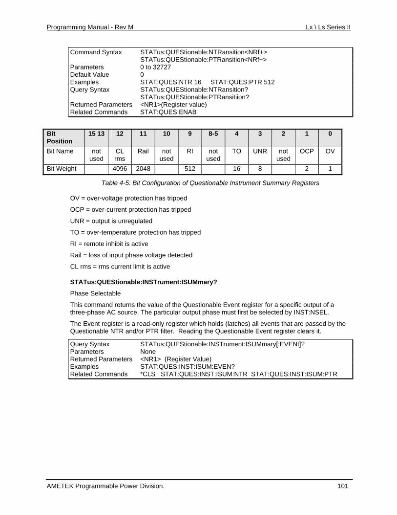
Programming Manual - Rev M Lx \ Ls Series II
Command Syntax STATus:QUEStionable:NTRansition<NRf+> STATus:QUEStionable:PTRansition<NRf+> Parameters 0 to 32727 Default Value 0 Examples STAT:QUES:NTR 16 STAT:QUES:PTR 512 Query Syntax STATus:QUEStionable:NTRansition? STATus:QUEStionable:PTRansitiion? Returned Parameters <NR1>(Register value) Related Commands STAT:QUES:ENAB
Bit Position
15 13 12 11 10 9 8-5 4 3 2 1 0
Bit Nam UNR not used
OCP OV e not used
CL rms
Rail not used
RI not used
TO
Bit Weig 6 2048 512 16 8 2 1 ht 409
Table 4-5: Bit Configuration of Questionable Instrument Summary Registers
OV = over-voltage protection has tripped
OCP = over-current protection has tripped
UNR = output is unregulated
ibit is ac
vents that are passed by the
ISUMmary[:EVENt]?
TO = over-temperature protection has tripped
RI = remote inh tive
Rail = loss of input phase voltage detected
CL rms = rms current limit is active
STATus:QUEStionable:INSTrument:ISUMmary?
Phase Selectable
This command returns the value of the Questionable Event register for a specific output of a three-phase AC source. The particular output phase must first be selected by INST:NSEL.
The Event register is a read-only register which holds (latches) all eQuestionable NTR and/or PTR filter. Reading the Questionable Event register clears it.
Query Syntax STATus:QUEStionable:INSTrument:Parameters None R urned Parameters <NR1> (Register Value) etExamples STAT:QUES:INST:ISUM:EVEN? Related Commands :ISUM:NTR STAT:QUES:INST:ISUM:PTR *CLS STAT:QUES:INST
AMETEK Programmable Power Division. 101
Programming Manual - Rev M Lx \ Ls Series II
STATus:QUEStionable:INSTrument:ISUMmary:CONDition?
Phase Selectable
This query returns the value of the Questionable Condition register for a specific output of a three-phase AC source. The particular output phase must first be selected by INST:NSEL.
The Conditio a read-onlyn register is register which holds the real-time (unlatched) questionable status of the Lx\Ls Series.
Query Syntax STATus:QUEStionable:INSTrument:ISUMmary:CONDition?Example STAT:QUES:INST:ISUM:COND? Returned Parameters <NR1> (Register value)
STATus:QUEStionable:INSTrument:ISUMmary:ENABle
Phase Selectable
This command sets or reads the value of the Questionable Enable register for a specific output of a three-phase AC source. The particular output phase must first be selected by INST:NSEL.
The Enable register is a mask for enabling specific bits from the Questionable Event register to set the questionable summary (QUES) bit of the Status Byte register. This bit (bit 3) is the logical OR of all the Questionable Event register bits that are enabled by the Questionable Status Enable register.
Command Syntax STATus:QUEStionable:INSTrument:ISUMmary:ENABle <NRf+> Parameters 0 to 32767 Default Value 0 Examples STAT:QUES:INST:ISUM:ENAB 18 Query Syntax STATus:QUEStionable:INSTrument:ISUMmary:ENABle? Returned Parameters <NR1> (Register value) Related Commands STAT:QUES:INST:ISUM:EVEN?
STATus:QUEStionable:INSTrument:ISUMmary:NTR STATus:QUEStionable:INSTrument:ISUMmary:PTR
These commands allow the values of the Questionable NTR (Negative-Transition) and PTR (Positive-Transition) registers to be set or read for a specific output of a three-phase AC source. The particular output phase must first be selected by INST:NSEL.
The NTR and PTR registers serve as polarity filters between the Questionable Enable and Questionable Event registers to cause the following actions:
• When a bit of the Questionable NTR register is set to 1, then a 1-to-0 transition of the corresponding bit of the Questionable Condition register causes that bit in the Questionable Event register to be set.
• When a bit of the Questionable PTR register is set to 1, then a 0-to-1 transition of the corresponding bit in the Questionable Condition register causes that bit in the Questionable Event register to be set.
• If the same bits in both NTR and PTR registers are set to 1, then any transition of that bit at the Questionable Condition register sets the corresponding bit in the Questionable Event register.
• If the same bits in both NTR and PTR registers are set to 0, then no transition of that bit at the Questionable Condition register can set the corresponding bit in the Questionable Event register.
AMETEK Programmable Power Division. 102
Programming Manual - Rev M Lx \ Ls Series II
Note: Setting a bit in the PTR or NTR filter can of itself generate positive or negative events in the corresponding Questionable Event register.
Command Syntax STATus:QUEStionable:INSTrument:ISUMmary :NTRansition<NRf> STATus:QUEStionable:INSTrument:ISUMmary :PTRansition<NRf> Parameters 0 to 32727 Default Value 0 Examples ST ST:ISUM:NTR 16 AT:QUES:IN ST ST:ISUM:PTR 512 AT:QUES:INQuery Syntax STATus:QUEStionable:INSTrument:ISUMmary:NTRansition? STATus:QUEStionable:INSTrument:ISUMmary:PTRansition? R d ramete s ter value) eturne Pa r <NR1> (RegisRelated Commands STAT:QUES:INST:ISUM:ENAB
AMETEK Programmable Power Division. 103
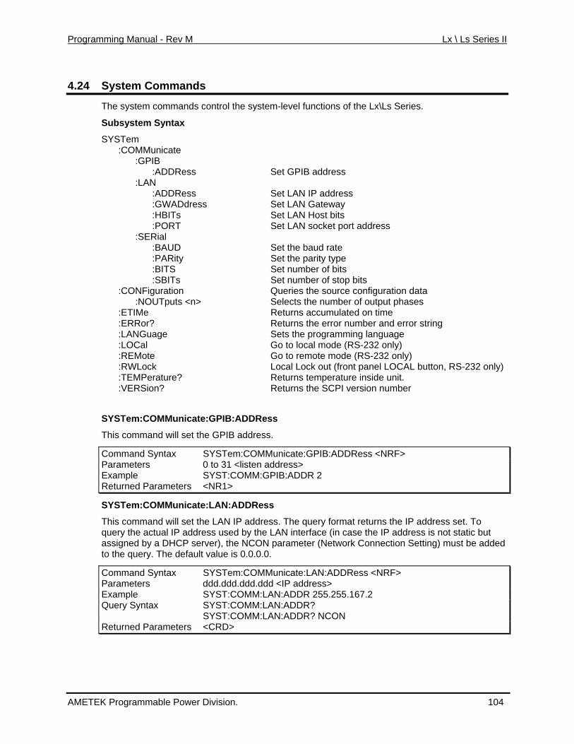
Programming Manual - Rev M Lx \ Ls Series II
4.24 System Commands
The system commands control the system-level functions of the Lx\Ls Series.
Subsystem Syntax
SYSTem :COMMunicate
s Set LAN Gateway Set LAN Host bits Set LAN socket port address
of bits tion data
me umber and error string
ing language Go to local mode (RS-232 only) Go to remote mode (RS-232 only) Local Lock out (front panel LOCAL button, RS-232 only)
Returns the SCPI version number
:COMMunicate:GPIB:ADDRess <NRF>
:GPIB :ADDRess Set GPIB address :LAN :ADDRess Set LAN IP address :GWADdre s :HBITs :PORT :SERial :BAUD Set the baud rate :PARity Set the parity type :BITS Set number :SBITs Set number of stop bits :CONFiguration Queries the source configura :NOU Tputs <n> Selects the number of output phases :ETIMe Returns accumulated on ti :ERRor? Returns the error n Sets the programm:LANGuage :LOCal :REMote :RWLock :TEMPerature? Returns temperature inside unit. :VERSion?
SYSTem:COMMunicate:GPIB:ADDRess
This command will set the GPIB address.
Command Syntax SYSTemParameters 0 to 31 <listen address> Example SYST:COMM:GPIB:ADDR 2 Returned Parameters <NR1>
SYSTem:COMMunicate:LAN:ADDRess
This comm e LAN IP address. The query form by the LAN interface (in case the IP address is not static but
a at returns the IP addresnd will set th s set. To r
er (Network Connection Setting) must be added
DRess <NRF>
query the actual IP add ess usedassigned by a DHCP server), the NCON parametto the query. The default value is 0.0.0.0.
Command Syntax SYSTem:COMMunicate:LAN:ADParameters ddd.ddd.ddd.ddd <IP address> Example SYST:COMM:LAN:ADDR 255.255.167.2 Query Sy SYST:COMM:LAN:ADDR? ntax SYST:COMM:LAN:ADDR? NCON Returned Parameters <CRD>
AMETEK Programmable Power Division. 104
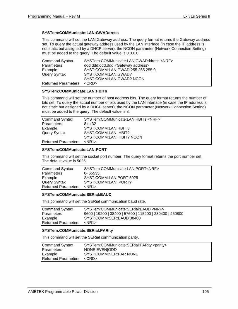
Programming Manual - Rev M Lx \ Ls Series II
SYSTem:COMMunicate:LAN:GWADdress
rns the Gateway address
ork Connection Setting)
:COMMunicate:LAN:GWADddress <NRF>
This command will set the LAN Gateway address. The query format retuset. To query the actual gateway address used by the LAN interface (in case the IP address is not static but assigned by a DHCP server), the NCON parameter (Netwmust be added to the query. The default value is 0.0.0.0.
Command Syntax SYSTemParameters ddd.ddd.ddd.ddd <Gateway address> Example SYST:COMM:LAN:GWAD 255.255.255.0 Query Syntax SYST:COMM:LAN:GWAD? SYST:COMM:LAN:GWAD? NCON Returned Paramete <CRD> rs
SYSTem:COMMunicate:LAN:HBITs
This command will set e numbeth r of host address bits. The query format returns the number of number of bits used by the LAN interface (in case the IP address is DHCP server), the NCON parameter (Network Connection Setting)
bits set. To query the actualnot static but assigned by a must be added to the query. The default value is 8.
Command Syntax SYSTem:COMMunicate:LAN:HBITs <NRF> Parameters 8 to 32 Example SYST:COMM:LAN:HBIT 8 Query Syntax SYST:COMM:LAN: HBIT? SYST:COMM:LAN: HBIT? NCON Returned Parameters <NR1>
SYSTem:COMMunicate:LAN:PORT
This command will set the socket port number. The query format returns the port number set. The default value is 5025.
Command Syntax SYSTem:COMMunicate:LAN:PORT<NRF> Parameters 0- 65535 Example SYST:COMM:LAN:PORT 5025 Query Syntax SYST:COMM:LAN: PORT? Returned Parameters <NR1>
SYSTem:COMMunicate:SERial:BAUD
This command will set the SERial communication baud rate.
Command Syntax SYSTem:COMMunicate:SERial:BAUD <NRF> Parameters 9600 | 19200 | 38400 | 57600 | 115200 | 230400 | 460800 Example SYST:COMM:SER:BAUD 38400 Returned Parameters <NR1>
SYSTem:COMMunicate:SERial:PARity
icate:SERial:PARity <parity>
This command will set the SERial communication parity.
Command Syntax SYSTem:COMMunParameters NONE|EVEN|ODD Example SYST:COMM:SER:PAR NONE Returned Parameters <CRD>
AMETEK Programmable Power Division. 105
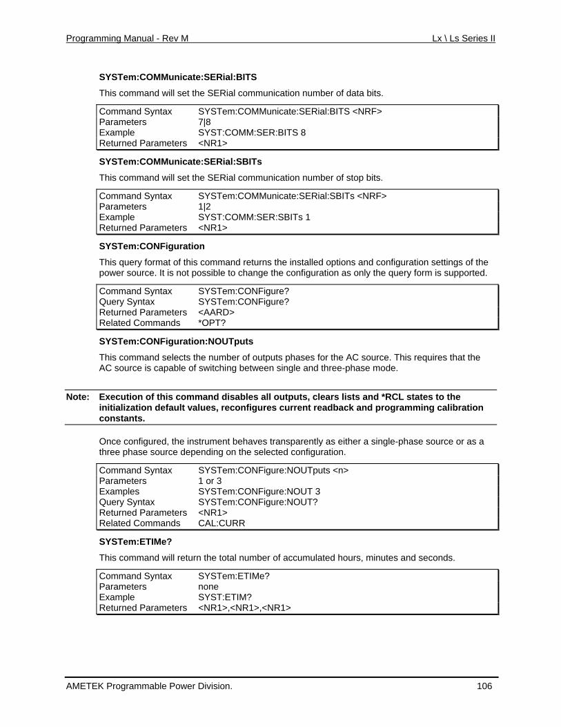
Programming Manual - Rev M Lx \ Ls Series II
SYSTem:COMMunicate:SERial:BITS
This command will set the SERial communication number of data bits.
Command Syntax SYSTem:COMMunicate:SERial:BITS <NRF> Parameters 7|8 Example SYST:COMM:SER:BITS 8 Returned Parameters <NR1>
SYSTem:COMMunicate:SERial:SBITs
This command will set e SERial commuth nication number of stop bits.
SYSTem:COMMunicate:SERial:SBITs <NRF> Command Syntax Parameters 1|2 Example SYST:COMM:SER:SBITs 1 Returned Parameters <NR1>
SYSTem:CONFiguration
This query format of this command returns the installed options and configuration settings of the power source. It is not possible to change the configuration as only the query form is supported.
Syntax ? Command SYSTem:CONFigureQuery Syntax SYSTem:CONFigure? Returned Parameters <AARD> Related Commands *OPT?
SYSTem:CONFiguration:NOUTputs
This command selects the number of outputs phases for the AC source. This requires that the AC source is capable of switching between single and three-phase mode.
Note: outputs, clears lists and *RCL states to the Execution of this command disables all initialization default values, reconfigures current readback and programming calibration constants.
Once configured, the instrument behaves transparently as either a single-phase source or as a three phase source depending on the selected configuration.
Command Syntax SYSTem:CONFigure:NOUTputs <n> Parameters 1 or 3 Examples SYSTem:CONFigure:NOUT 3 Query Syntax SYSTem:CONFigure:NOUT? Returned Parameters <NR1> Related Commands CAL:CURR
SYSTem:ETIMe?
This command will return the total number of accumulated hours, minutes and seconds.
Command Syntax SYSTem:ETIMe? Parameters none Example SYST:ETIM? Returned Paramete <NR1>,<NR1>,<NRrs 1>
AMETEK Programmable Power Division. 106
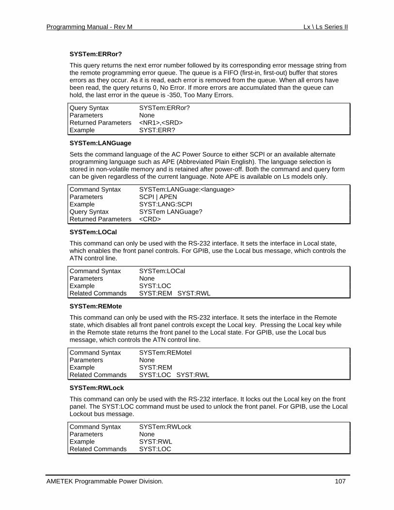
Programming Manual - Rev M Lx \ Ls Series II
SYSTem:ERRor?
This query returns the next error number followed by its corresponding error message stringthe remot
from e programming error queue. The queue is a FIFO (first-in, first-out) buffer that stores
rrors are accumulated than the queue can rs.
SYSTem:ERRor?
errors as they occur. As it is read, each error is removed from the queue. When all errors have been read, the query returns 0, No Error. If more ehold, the last error in the queue is -350, Too Many Erro
Query Syntax Parameters None Returned Parameters <NR1>,<SRD> Example SYST:ERR?
SYSTem:LANGuage
Source to either SCPI or an available alternate eviated Plain English). The language selection is
APE is available on Ls models only.
Command Syntax SYSTem:LANGuage:<language>
Sets the comm uage of the AC Powerand langprogramming language such as APE (Abbrstored in non-volatile m mory ane d is retained after power-off. Both the command and query form can be given regardless of the current language. Note
Parameters SCPI | APEN Example SYST:LANG:SCPI Query Syntax SYSTem LANGuage? Returned Parameters <CRD>
SYSTem:LOCal
This command can only be used with the RS-232 interface. It sets the interface in Local state, which enables the front panel controls. For GPIB, use the Local bus message, which controls the ATN control line.
Command Syntax SYSTem:LOCal Parameters None Example SYST:LOC Related Commands SYST:REM SYST:RWL
SYSTem:REMote
This command can only be used with the RS-232 interface. It sets the interface in the Remote state, which disables all front panel controls except the Local key. Pressing the Local key while in the Remote state returns the front panel to the Local state. For GPIB, use the Local bus message, which controls the ATN control line.
Command Syntax SYSTem:REMotel Parameters None Example SYST:REM Related Commands SYST:LOC SYST:RWL
SYSTem:RWLock
This command can only be used with the RS-232 interface. It locks out the Local key on the front panel. The SYST:LOC command must be used to unlock the front panel. For GPIB, use the Local Lockout bus message.
Command Syntax SYSTem:RWLock Parameters None Example SYST:RWL Related Commands SYST:LOC
AMETEK Programmable Power Division. 107
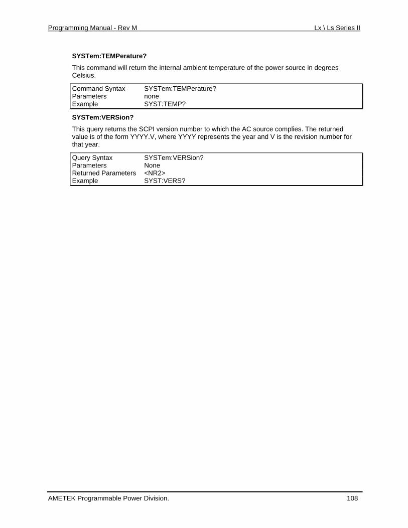
Programming Manual - Rev M Lx \ Ls Series II
SYSTem:TEMPerature?
This command will return the internal ambient temperature of the power source in degrees Celsius.
Command Syntax SYSTem:TEMPerature? Parameters none Example SYST:TEMP?
S Tem:VERSio YS n?
his to which the AC soT query returns the SCPI version number urce complies. The returned value is of the form YYYY.V, where YYYY represents the year and V is the revision number for that year.
Query Syntax SYSTem:VERSion? Parameters None Returned Parameters <NR2> Example SYST:VERS?
AMETEK Programmable Power Division. 108
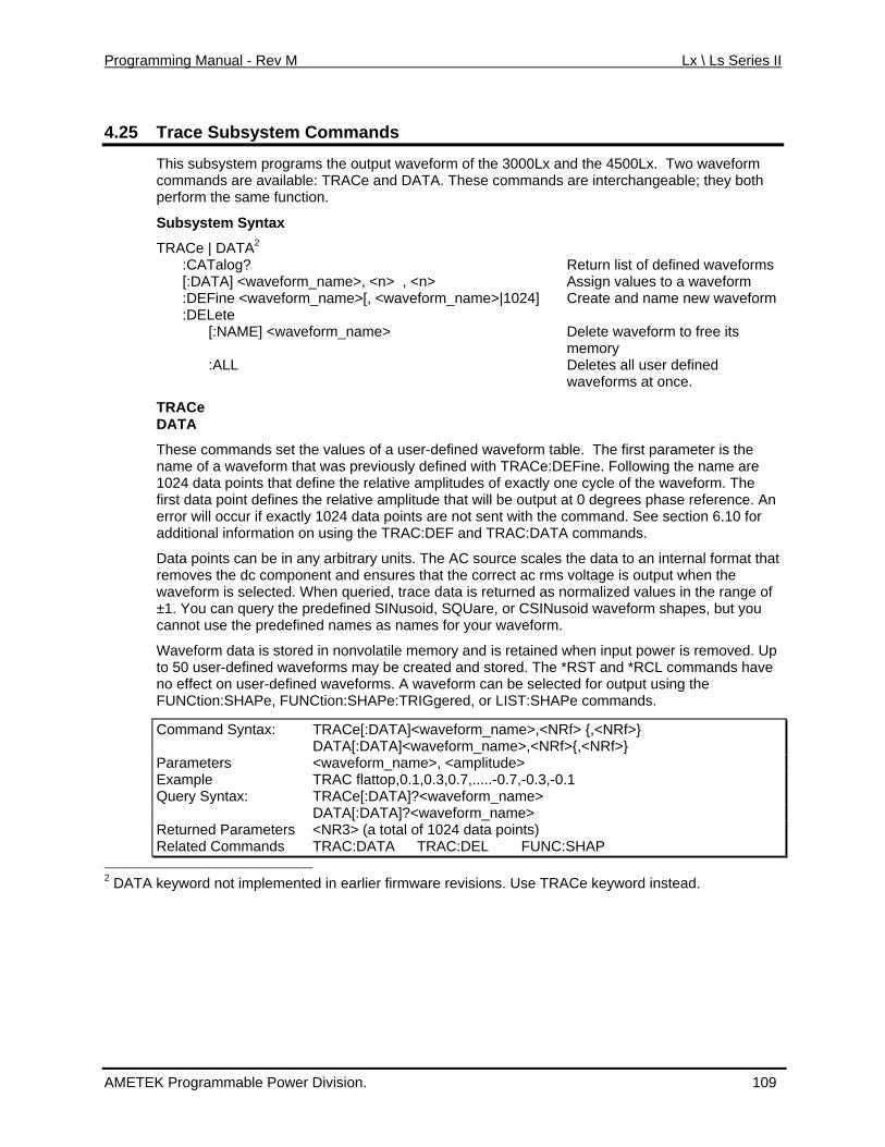
Programming Manual - Rev M Lx \ Ls Series II
4.25 m Commands Trace Subsyste
This subsystem programs the output waveform of the 3000Lx and the 4500Lx. Two waveformcommands are available: TRACe and DATA. These commands are interchangeable; they both
ues to a waveform eform_name>[, <waveform_name>|1024] Create and name new waveform
] <waveform_name> Delete waveform to free its
hat will be output at 0 degrees phase reference. An 0 for
ales the data to an internal format that output when the values in the range of
y the predefined SINusoid, SQUare, or CSINusoid waveform shapes, but you edefined names as names for your waveform.
mands.
perform the same function.
Subsystem Syntax
TRACe | DATA2 :CATalog? Return list of defined waveforms [:DATA] <waveform_name>, <n> , <n> Assign val :DEFine <wav :DELete [:NAME
memory :ALL Deletes all user defined
waveforms at once.
TRACe DATA
These commands set the values of a user-defined waveform table. The first parameter is the name of a waveform that was previously defined with TRACe:DEFine. Following the name are 1024 data points that define the relative amplitudes of exactly one cycle of the waveform. The first data point defines the relative amplitude terror will occur if exactly 1024 data points are not sent with the command. See section 6.1additional information on using the TRAC:DEF and TRAC:DATA commands.
Data points can be in any arbitrary units. The AC source sct removes the dc component and ensures that the correc ac rms voltage is
waveform is selected. When queried, trace data is returned as normalized ±1. You can quercannot use the pr
Waveform data is stored in nonvolatile memory and is retained when input power is removed. Up to 50 user-defined waveforms may be created and stored. The *RST and *RCL commands have no effect on user-defined waveforms. A waveform can be selected for output using the FUNCtion:SHAPe, FUNCtion:SHAPe:TRIGgered, or LIST:SHAPe com
Command Syntax: TRACe[:DATA]<waveform_name>,<NRf> {,<NRf>} DATA[:DATA]<waveform_name>,<NRf>{,<NRf>} Parameters <waveform_name>, <amplitude> Example TRAC flattop,0.1,0.3,0.7,.....-0.7,-0.3,-0.1 Query Syntax: TRACe[:DATA]?<waveform_name> DATA[:DATA]?<waveform_name> Returned Parameters <NR3> (a total of 1024 data points) Related Commands TRAC:DATA TRAC:DEL FUNC:SHAP
2 DATA ente evisions. Use TRACe keyword instead. keyword not implem d in earlier firmware r
AMETEK Programmable Power Division. 109
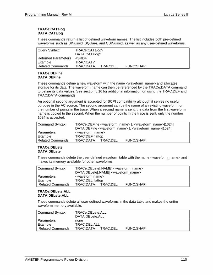
Programming Manual - Rev M Lx \ Ls Series II
TRACe:CATalog DATA:CATalog
These commands return a list of defined waveform names. The list includes both pre-defined waveforms such as SINusoid, SQUare, and CSINusoid, as well as any user-defined wavefo
Query Syntax: TRACe:CATalog?
rms.
DATA:CATalog? Returned Parameters <SRD> Example TRAC:CAT? Related Commands TRAC:DATA TRAC:DEL FUNC:SHAP
TRACe:DEFine
he e c rm with th s e can then be referenced by the TRACe:DATA command
ection 6.10 for additional information on using the TRAC:DEF and
l second argument is accepted for SCPI compatibility although it serves no useful
first waveform t, only the number
e <waveform_name> [, <waveform_name>|1024]
DATA:DEFine
T s ommands define a new wavefo e name <waveform_name> and alloe waveform nam
catestorage for its data. Tho definet its data values. See s
TRAC:DATA commands.
An optionapurpose in the AC source. The second argument can be the name of an existing waveform, or the number of points in the trace. When a second name is sent, the data from the name is copied to the second. When the number of points in the trace is sen1024 is accepted.
Command Syntax: TRACe:DEFin DATA:DEFine m_name> [, <waveform_name>|1024] <waveforP ameters <wavar eform_name> Example TRAC:DEF flattop Related Commands TRAC EL FUNC:SHAP :DATA TRAC:D
TRACe:DELete DATA:DELete
These commands delete the user-defined waveform table with the name <waveform_name> and ailable for other waveforms.
[:NAME] <waveform_name>
makes its memory av
Command Syntax: TRACe:DELete DATA:DELete[:NAME] <waveform_name> Parameters <waveform name> Example TRAC:DEL flattop Related Commands TRAC:DATA TRAC:DEL FUNC:SHAP
TRACe:DELete:ALL DATA:DELete:ALL
These commands delete all user-defined waveforms in the data table and makes the entire waveform memory available.
Command Syntax: TRACe:DELete:ALL DATA:DELete:ALL Parameters none Example TRAC:DEL:ALL Related Commands TRAC:DATA TRAC:DEL FUNC:SHAP
AMETEK Programmable Power Division. 110
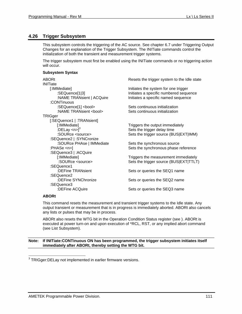
Programming Manual - Rev M Lx \ Ls Series II
4.26 Trigger Subsystem
This subsystem contr the trols iggering of the AC source. See chapter 6.7 under Triggering Output Changes for an explanation of the Trigger Subsystem. The INITiate commands control the
transient and measurement trigger systems.
stem must first be enabled using the INITiate commands or no triggering action
Resets the trigger system to the Idle state
] <bo us initialization :NAME TRANsien
[:SEQuence1 | :TRAN [:IMMediate] Triggers the output immediately
3 sour source (BUS|EXT|IMM)
onous source ase reference
Triggers the measurement immediately Sets the trigger source (BUS|EXT|TTLT)
e SEQ1 name
the SEQ2 name
igger systems to the Idle state. Any borted. ABORt also cancels
ondition Status register (see ). ABORt is ower turn- upon execution of *RCL, RST, or any implied abort command
Note: If INITiate:CONTinuous ON has been programmed, the trigger subsystem initiates itself
initialization of both the
The trigger subsywill occur.
Subsystem Syntax
ABORt INITiate [:IMMediate] Initiates the system for one trigger :SEQuence[1|3] Initiates a specific numbered sequence :NAME TRANsient | ACQuire Initiates a specific named sequence :CONTinuous :SEQuence[1 ol> Sets continuo t <bool> Sets continuous initialization TRIGger sient] :DELay <n>] Sets the trigger delay time :SOURce < ce> Sets the trigger :SEQuence2 | :SYNCronize :SOURce PHAse | IMMediate Sets the synchr :PHASe <n>] Sets the synchronous ph :SEQuence3 | :ACQuire [:IMMediate] :SOURce <source> :SEQuence1 :DEFine TRANsient Sets or queries th :SEQuence2 :DEFine SYNChronize Sets or queries :SEQuence3 :DEFine ACQuire Sets or queries the SEQ3 name
ABORt
This command resets the measurement and transient troutput transient or measurement that is in progress is immediately aany lists or pulses that may be in process.
ABORt also resets the WTG bit in the Operation Cexecuted at p on and(see List Subsystem).
immediately after ABORt, thereby setting the WTG bit.
3 TRIGger:DELay not implemented in earlier firmware versions.
AMETEK Programmable Power Division. 111
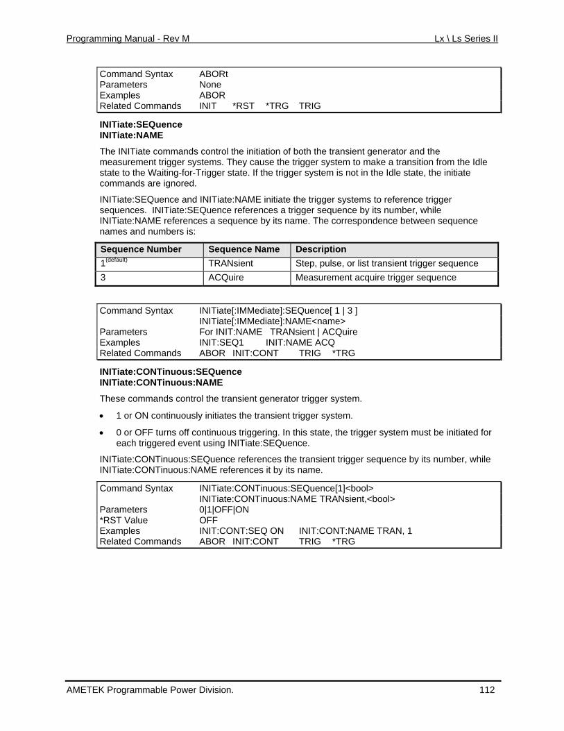
Programming Manual - Rev M Lx \ Ls Series II
Command Syntax ABORt Parameters None Examples ABOR Related Commands INIT *RST *TRG TRIG
INITiate:SEQuence INITiate:NAME
The INITiate commands control the initiation of both the transient generator and the ransition from the Idle
, the initiate
e and INITiate:NAME initiate the trigger systems to reference trigger
measurement trigger systems. They cause the trigger system to make a tstate to the Waiting-for-Trigger state. If the trigger system is not in the Idle statecommands are ignored.
INITiate:SEQuencsequences. INITiate:SEQuence references a trigger sequence by its number, while INITiate:NAME references a sequence by its name. The correspondence between sequence names and numbers is:
Sequence Number Sequence Name Description 1(default) TRANsient Step, pulse, or list transient trigger sequence 3 ACQuire Measurement acquire trigger sequence
Command Sy INIntax Tiate[:IMMediate]:SEQuence[ 1 | 3 ] INITiate[:IMMediate]:NAME<name> Parameters For INIT:NAME TRANsient | ACQuire Examples INIT:SEQ1 INIT:NAME ACQ Related Commands ABOR INIT:CONT TRIG *TRG
INITiate:CONTinuous:SEQuence INITiate:CONTinuous:NAME
These commands control the transient generator trigger system.
•
INIT inuous:S y its number, while INIT uous:N
>
• 1 or ON continuously initiates the transient trigger system.
0 or OFF turns off continuous triggering. In this state, the trigger system must be initiated for each triggered event using INITiate:SEQuence.
iate:CONT EQuence references the transient trigger sequence biate:CONTin AME references it by its name.
Command Syntax INITiate:CONTinuous:SEQuence[1]<bool INITiate:CONTinuous:NAME TRANsient,<bool> Parameters 0|1|OFF|ON *RST Value OFF Examples INIT:CONT:SEQ ON INIT:CONT:NAME TRAN, 1 Related Commands ABOR INIT:CONT TRIG *TRG
AMETEK Programmable Power Division. 112
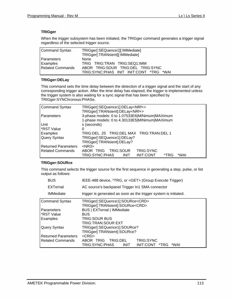
Programming Manual - Rev M Lx \ Ls Series II
TRIGger
When the trigger subsystem has been initiated, the TRIGger command generates a trigger signal regardless of the selected trigger source.
Command Syntax TRIGger[:SEQuence1][:IMMediate] TRIGger[:TRANsient][:IMMediate] Parameters None Examples TRIG TRIG:TRAN TRIG:SEQ1:IMM Related ABOR TRIG:SOUR TRIG:DEL TRIG:SYNC Commands TRIG:SYNC:PHAS INIT INIT:CONT *TRG *WAI
TRIGger:DELay
This command sets the time delay between the detection of a trigger signal and the start of any g trigger ac lay has elapsed, the trigger is implemented unless stem is als
correspondin tion. After the time dethe trigger sy o waiting for a sync signal that has been specified by TRIGger:SYNChronous:PHASe.
Command Syntax TRIGger[:SEQuence1]:DELay<NRf+> TRIGger[:TRANsient]:DELay<NRf+> Parameters 3-phase models: 0 t 7533E6|MINio 1.0 mum|MAXimum 1-phase models: 0 to 4.30133E5|MINimum|MAXimum Unit s (seconds) *RST Value 0 Examples TRIG:DEL .25 TRIG:DEL MAX TRIG:TRAN:DEL 1 Query Syntax TRIGger[:SEQuence1]:DELay? TRIGger[:TRANsient]:DELay? Returned Parameters <NR3> Related Commands ABOR TRIG TRIG:SOUR TRIG: SYNC TRIG:SYNC:PHAS INIT INIT:CONT *TRG *WAI
TRIGger:SOURce
selects t ing a step, pulse, or list s:
er)
TRIGger[:SEQuence1]:SOURce<CRD>
This comm he trigger source for the first sequence in generatand output as follow
BUS IEEE-488 device, *TRG, or <GET> (Group Execute Trigg
EXTernal AC source's backpanel Trigger In1 SMA connector
IMMediate trigger is generated as soon as the trigger system is initiated.
Command Syntax TRIGger[:TRANsient]:SOURce<CRD> Parameters BUS | EXTernal | IMMediate *RST Value BUS Examples TRIG:SOUR BUS TRIG:TRAN:SOUR EXT Query Syntax TRIGger[:SEQuence1]:SOURce? TRIGger[:TRANsient]:SOURce? Returned Parameters <CRD> Related Commands ABOR TRIG TRIG:DEL TRIG:SYNC TRIG:SYNC:PHAS INIT INIT:CONT *TRG *WAI
AMETEK Programmable Power Division. 113
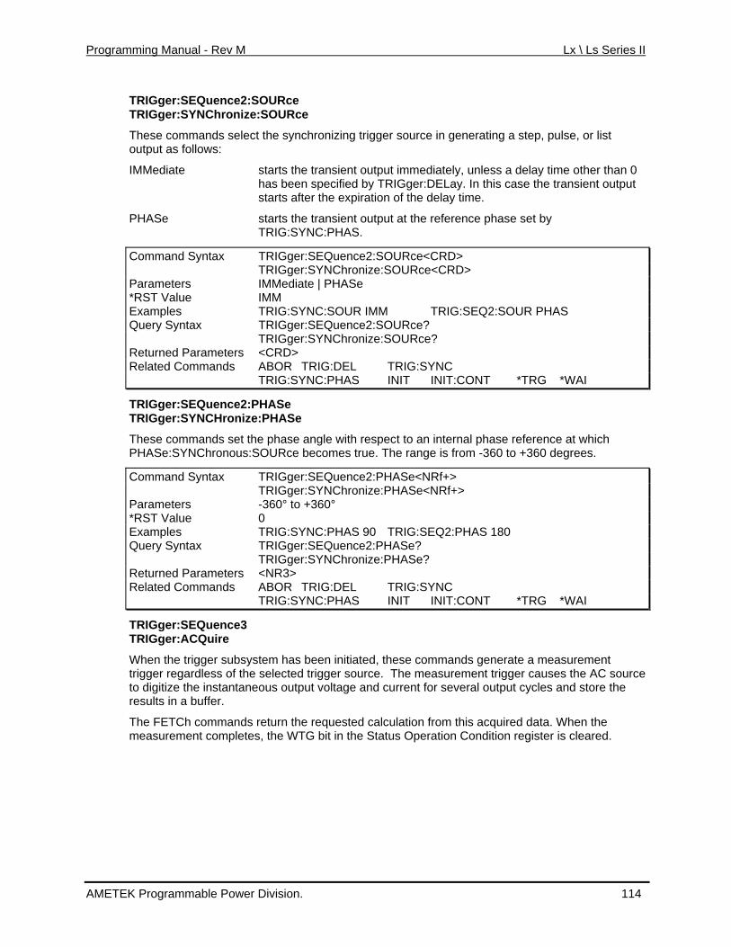
Programming Manual - Rev M Lx \ Ls Series II
TRIGger:SEQuence2:SOURce TRIGger:SYNChronize:SOURce
These commands select the synchronizing trigger source in generating a step, pulse, or list
n 0 specified by TRIGger:DELay. In this case the transient output r the expiration of the delay time.
Command Syntax
output as follows:
IMMediate starts the transient output immediately, unless a delay time other thahas beenstarts afte
PHASe starts the transient output at the reference phase set by TRIG:SYNC:PHAS.
TRIGger:SEQuence2:SOURce<CRD> TRIGger:SYNChronize:SOURce<CRD> Parameters IMMediate | PHASe *RST Value IMM Examples TRIG:SYNC:SOUR IMM TRIG:SEQ2:SOUR PHAS Query Syntax TRIGger:SEQuence2:SOURce? TRIGger:SYNChronize:SOURce? Returned Par <CRDameters > Related Commands ABOR TRIG:DEL TRIG:SYNC TRIG:SYNC:PHAS INIT INIT:CONT *TRG *WAI
TRIGger:SEQuence2:PHASe TRIGger:SYNCHroniz :PHASe e
r:SEQuence2:PHASe<NRf+>
These commands set the phase angle with respect to an inte phase referenrnal ce at which PHASe:SYNChronous:SOURce becomes true. The range is from -360 to +360 degrees.
Command Syntax TRIGge TRIGger:SYNChronize:PHASe<NRf+> Parameters -360° to +360° *RST Value 0 Examples TRIG:SYNC:PHAS 90 TRIG:SEQ2:PHAS 180 Query Syntax TRIGger:SEQuence2:PHASe? TRIGger:SYNChronize:PHASe? Returned Parameters <NR3> Related Commands ABOR TRIG:DEL TRIG:SYNC TRIG:SYNC:PHAS INIT INIT:CONT *TRG *WAI
TRIGger:SEQuence3 TRIGger:ACQuire
asurement s the AC source
and store the
The FETCh commands return the requested calculation from this acquired data. When the measurement completes, the WTG bit in the Status Operation Condition register is cleared.
When the trigger subsystem has been initiated, these commands generate a metrigger regardless of the selected trigger source. The measurement trigger causeto digitize the instantaneous output voltage and current for several output cycles results in a buffer.
AMETEK Programmable Power Division. 114
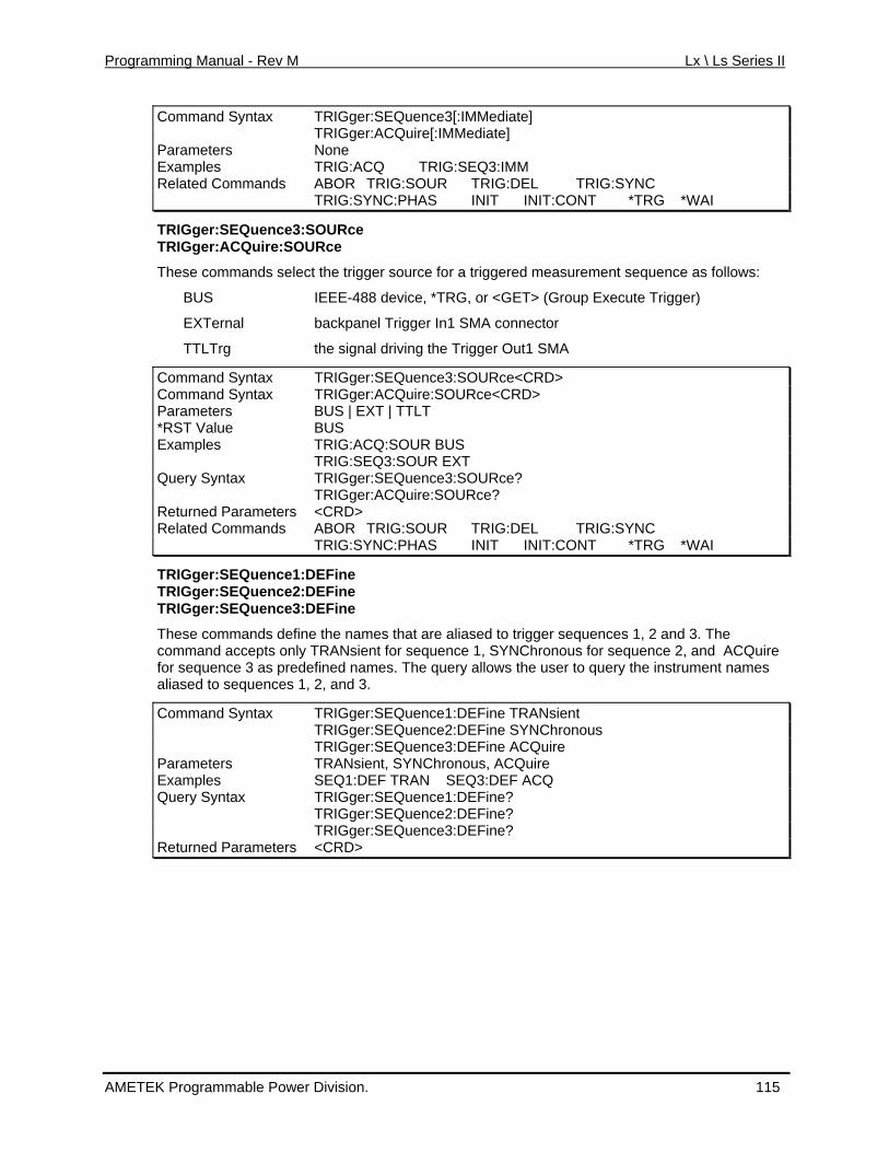
Programming Manual - Rev M Lx \ Ls Series II
Command Syntax TRIGger:SEQuence3[:IMMediate] TRIGger:ACQuire[:IMMediate] Parameters None Examples TRIG:ACQ TRIG:SEQ3:IMM Related Commands ABOR TRIG:SOUR TRIG:DEL TRIG:SYNC TRIG:SYNC:PHAS INIT INIT:CONT *TRG *WAI
TRIGger:SEQuence3:SOURce TRIGger:ACQuire:SOURce
These commands select the trigger source for a triggered measurement sequence as follows:
BUS IEEE-488 device, *TRG, or <GET> (Group Execute Trigger)
EXTernal backpanel Trigger In1 SMA connector
TTLTrg the signal driving the Trigger Out1 SMA
Command Syntax TRIGger:SEQuence3:SOURce<CRD> Command Syntax TRIGger:ACQuire:SOURce<CRD> Parameters BUS | EXT | TTLT *RST V BUS alue Examples TRIG:ACQ:SOUR BUS TRIG:SEQ3:SOUR EXT Query Sy TRIGger:SEQuence3:Sntax ? OURce TRIGger:ACQuire:SOURce? Returned Parameters <CRD> Related Commands ABOR TRIG:SOUR TRIG:DEL TRIG:SYNC TRIG:SYNC:PHAS INIT INIT:CONT *TRG *WAI
TRIGger:SEQuence1:DEFine TRIGger:SEQuence2:DEFine
er:SE EFine TRIGg ce3:DQuen
ands re aliased to trigger sequences 1, 2 and 3. The NChronous for sequence 2, and ACQuire
e user to query the instrument names
nd Syntax TRANsient
These comm define the names that acommand accepts only TRANsient for sequence 1, SYfor sequence 3 as predefined names. The query allows thaliased to sequences 1, 2, and 3.
Comma TRIGger:SEQuence1:DEFine TRIGger:SEQuence2:DEFine SYNChronous TRIGger:SEQuence3:DEFine ACQuire Parameters TRANsient, SYNChronous, ACQuire Examples SEQ1:DEF TRAN SEQ3:DEF ACQ Query Syntax TRIGger:SEQuence1:DEFine? TRIGger:SEQuence2:DEFine? TRIGger:SEQuence3:DEFine? Returned Parameters <CRD>
AMETEK Programmable Power Division. 115
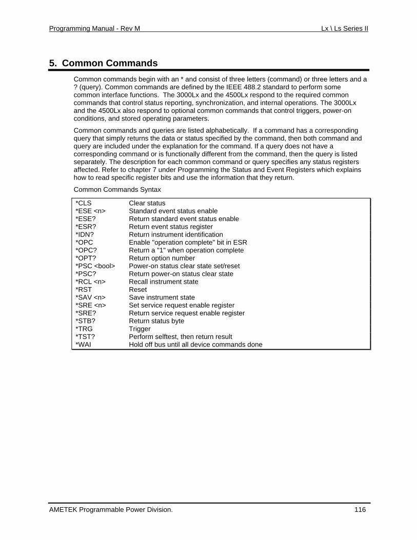
Programming Manual - Rev M Lx \ Ls Series II
5. Common Commands Common commands begin with an * and consist of three letters (command) or three letters and a? (query). Common commands are defined by the
IEEE 488.2 standard to perform some
m The 3000Lx and the 4500Lx respond to the required common hronization, and internal operations. The 3000Lx
d to optional common commands that control triggers, power-on n parameters.
m nds and queries are listed alphabetically. If a command has a corresponding e returns the data or status specified by the command, then both command and e under the explanation for the command. If a query does not have a
corresponding command or is functionally different from the command, then the query is listed cript each common command or query specifies any status registers
ming the Status and Event Registers which explains use the information that they return.
co mon interface functions.commands that control status reporting, syncan the 4500Lx also respondco ditions, and stored operating
Co mon commaqu ry that simply qu ry are included
separately. The des ion for affected. Refer to chapter 7 under Programhow to read specific register bits and
Common Commands Syntax
*CLS Clear status *ESE <n> Standard event status enable *ESE? Return standard event status enable *ESR? Return event status register *IDN? Return instrument identification *OPC Enable "operation complete" bit in ESR *OPC? Return a "1" when operation complete *OPT? Return option number *PSC <b Pow n sta r sta /reseool> er-o tus clea te set t *PSC? Return power-on status clear state *RCL <n> Recall instrument state *RST Reset *SAV <n> Save instrument state *SRE <n> Set service request enable register *SRE? Return service request enable register *ST us byte B? Return stat *TRG Trigger *TST lftest, then return re? Perform se sult *WA off bus until all device com dI Hold man s done
AMETEK Programmable Power Division. 116
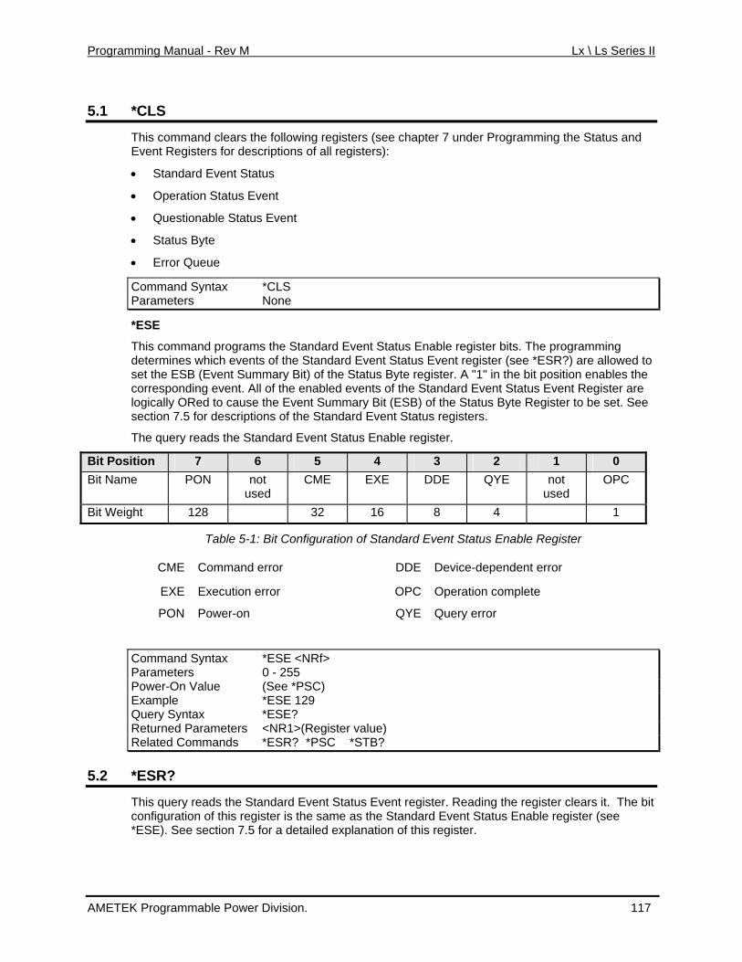
Programming Manual - Rev M Lx \ Ls Series II
5.1 *CLS
This command clears the following registers (see chapter 7 under Programming the Status and Event Registers for descriptions of all registers):
d Event Status
onable Status Event
• Standar
• Operation Status Event
• Questi
• Status Byte
• Error Queue
C *CLS ommand Syntax P None arameters
*ESE
This command programs the Standard Event Status Enable register bits. The programming which events of the Standard Event Status Event register (see *ESR?) are allowed to (Event Summary Bit) of the Status Byte register. A "1" in the bit position enables the
are See
determines set the ESBcorresponding event. All of the enabled events of the Standard Event Status Event Registerlogically ORed to cause the Event Summary Bit (ESB) of the Status Byte Register to be set.section 7.5 for descriptions of the Standard Event Status registers.
The query reads the Standard Event Status Enable register.
Bit Position 7 6 5 4 3 2 1 0 Bit Name PON not
used CME EXE DDE QYE not
used OPC
Bit Weight 128 32 16 8 4 1
Table 5-1: Bit Configuration of Standard Event Status Enable Register
CME Command error DDE Device-dependent error
EXE Execution error OPC Operation complete
PON Power-on QYE Query error
tax Rf>
Command Syn *ESE <NParameters 0 - 255 Power-On Value (See *PSC) Example *ESE 129 Query Syntax *ESE? Returned Parameters <NR1>(Register value) Related Commands *ESR? *PSC *STB?
5.2 *ESR?
This query reads the S ndard Eveta nt Status Event register. Reading the register clears it. The bit configuration of this register is the same as the Standard Event Status Enable register (see
section 7.5 for a detailed explanation of this register. *ESE). See
AMETEK Programmable Power Division. 117
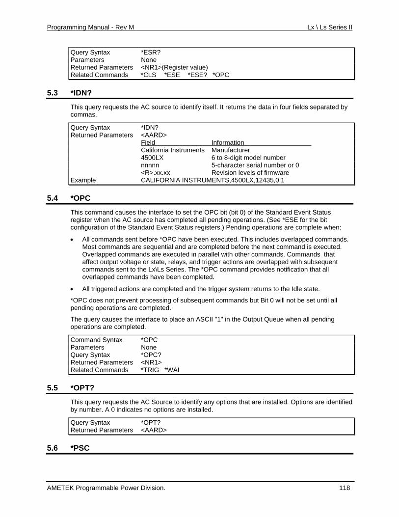
Programming Manual - Rev M Lx \ Ls Series II
Query Syntax *ESR? Parameters None Returned Parameters <NR1>(Register value) Related Comm *CLS *ESE *ESE? *OPC ands
5.3 *IDN?
This query requests the AC source to identify itself. It returns the data in four fields separated by commas.
Query Syntax *IDN? Returned Pa <AARD> rameters Field Information California Instruments Manufacturer 4500LX 6 to 8-digit model number nnnnn 5-character serial number or 0 <R>.xx.xx Revision levels of firmware Example CALIFORNIA INSTRUMENTS,4500LX,12435,0.1
5.4 *OPC
This command causes the interface to set the OPC bit (bit 0) of the Standard Event Statusre when the AC sour
gister ce has completed all pending operations. (See *ESE for the bit
configuration of the Standard Event Status registers.) Pending operations are complete when:
.
executed in parallel with other commands. Commands that
een completed.
ns are completed.
he in e an ASCII "1" in the Output Queue when all pending
• All commands sent before *OPC have been executed. This includes overlapped commandsMost commands are sequential and are completed before the next command is executed. Overlapped commands areaffect output voltage or state, relays, and trigger actions are overlapped with subsequent commands sent to the Lx\Ls Series. The *OPC command provides notification that all overlapped commands have b
• All triggered actions are completed and the trigger system returns to the Idle state.
*OPC does not prevent processing of subsequent commands but Bit 0 will not be set until all pending operatio
The query causes t terface to placoperations are completed.
Command Syntax *OPC Parameters None Query Syntax *OPC? Returned Parameters <NR1> Related Commands *TRIG *WAI
5.5 *OPT?
This query requests th rce tha lled. dica ons are i
uery Syntax *OPT?
e AC Sou to identify any options t are insta Options are identifiedby number. A 0 in tes no opti nstalled.
QReturned Parameters <AARD>
5.6 *PSC
AMETEK Programmable Power Division. 118
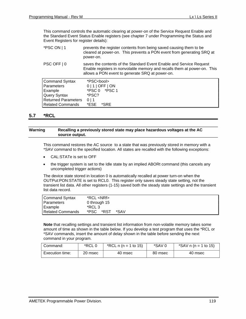
Programming Manual - Rev M Lx \ Ls Series II
This command controls the automatic clearing at power-on of the Service Request Enable and d Event Status Enable registers (see chapter 7 under Programming the Status and sters for register details):
t
ntents of the Standard Event Enable and Service Request Enable registers in nonvolatile memory and recalls them at power-on. This
w event to ge w n.
Command Syntax
the StandarEvent Regi
*PSC ON | 1 prevents the register contents from being saved causing them to be cleared at power-on. This prevents a PON event from generating SRQ apower-on.
PSC OFF | 0 saves the co
allo s a PON ne RQ at porate S er-o
*PSC<bool> Parameters 0 | 1 | OFF | ON Example *PSC 0 *PSC 1 Query Syntax *PSC? Returned Parameters 0 | 1 Related Comma S *SRE nds *E E
5.7 *RCL
Warning Recalling a prev stored state may u es at the AC iously place hazardo s voltag source output.
This command restores the AC source to a stat s red in memory with a *SAV comm c location. All sta t ollowing exceptions:
• CAL:ST
• the trigger system is set to the Idle state by an implied ABORt command (this cancels any uncompleted trigger actions)
The device state stored in location 0 is automatically recalled at power turn-on when the OUTPut:PO This regi a te setting, not the transient list data. All other registers (1-15) saved both the steady state settings and the transient list data record
Command Syntax *RCL <NRf>
e that was previou ly stoand to the spe ified tes are recalled wi h the f
ATe is set to OFF
N:STATE is set to RCL0. ster only saves ste dy sta
.
Pa t h 15 rameters 0 hrougExample *RCL 3 Related S *RST *S Commands *P C AV
N transient list information from non-volatile memory takes some amount of time as shown in the table below. If you develop a test program that uses the *RCL or *SAV commands, insert the amount of delay shown in the table before sending the next command in your program.
Command: *RCL *SAV n (n = 1 to 15)
ote that recalling settings and
0 *RCL n (n = 1 to 15) *SAV 0
Execution time: 20 msec 40 msec 80 msec 40 msec
AMETEK Programmable Power Division. 119
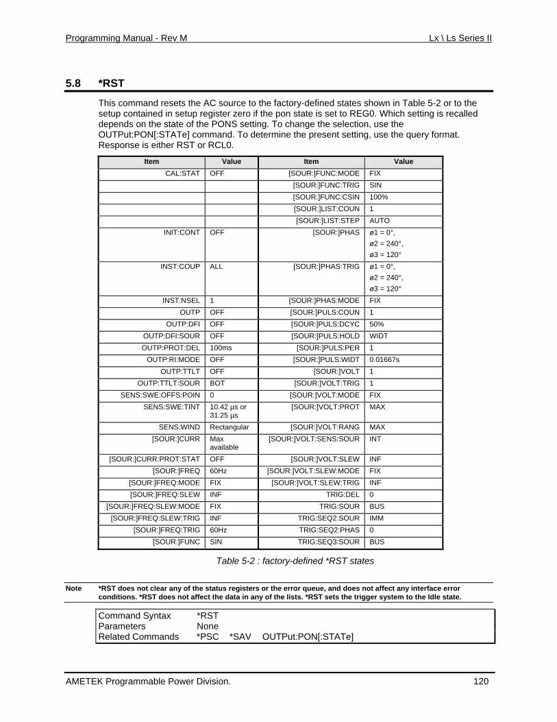
Programming Manual - Rev M Lx \ Ls Series II
5.8 *RST
This command resets the AC source to the factory-defined states shown in Table 5-2 or to the setup contained in setup register zero if the pon state is set to REG0. Which setting is recalleddepends on the state of the PONS setting. To change the selection
, use the
he present setting, use the query format. RST .
OUTPut:PON[:STATe] command. To determine tResponse is either or RCL0
Item V lue a Item Value CAL:STAT OFF [SOUR:]FUNC:MODE FIX
[SOUR:]FUNC:TRIG SIN [SOUR:]FUNC:CSIN 100% [SOUR:]LIST:COUN 1 [SOUR:]LIST:STEP AUTO
INIT:CONT OFF = 0°, 240°, 120°
[SOUR:]PHAS ø1 ø2 = ø3 =
INST:COUP ALL [SOUR:]PHAS:TRIG ø1 = 0°, ø2 = 240°, ø3 = 120°
INST:NSEL 1 [SOUR:]PHAS:MODE FIX OUTP OFF [SOUR:]PULS:COUN 1
OUTP:DFI OFF [SOUR:]PULS:DCYC 50% OUTP:DFI:SOUR OFF [SOUR:]PULS:HOLD WIDT OUTP:PROT:DEL 100ms [SOUR:]PULS:PER 1
OUTP:RI:MODE OFF [SOUR:]PULS:WIDT 0.01667s OUTP:TTLT OFF [SOUR:]VOLT 1
OUTP:TTLT:SOUR BOT [SOUR:]VOLT:TRIG 1 SENS:SWE:OFFS:POIN 0 [SOUR:]VOLT:MODE FIX
SENS:SWE:TINT 10.42 µs or 31.25 µs
[SOUR:]VOLT:PROT MAX
SENS:WIND Rectangular [SOUR:]VOLT:RANG MAX [SOUR:]CURR Max
e availabl[SOUR:]VOLT:SENS:SOUR INT
[SOUR:]CURR:PROT:STAT OFF [SOUR:]VOLT:SLEW INF [SOUR:]FREQ 60Hz [SOUR:]VOLT:SLEW:MODE FIX
[SOUR:]F E FIX REQ:MOD [SOUR:]VOLT:SLEW:TRIG INF [SOUR:]FREQ:SLEW INF TRIG:DEL 0
[SOUR:]FREQ:SLEW:M E FIX OD TRIG:SOUR BUS [SOUR:]FREQ:SLEW:TRIG INF TRIG:SEQ2:SOUR IMM
[SOUR:]FREQ:TRIG 60Hz TRIG:SEQ2:PHAS 0 [SOUR:]FUNC SIN TRIG:SEQ3:SOUR BUS
Table 5-2 : factory-defined *RST states
*RST does not clear any of the status registers or the error queue, and does not affect any interface error Note conditions. *RST does not affect the data in any of the lists. *RST sets the trigger system to the Idle state.
Command Syntax *RST Parameters None R man PS OUTPut:PON[:STATe] elated Com ds * C *SAV
AMETEK Programmable Power Division. 120
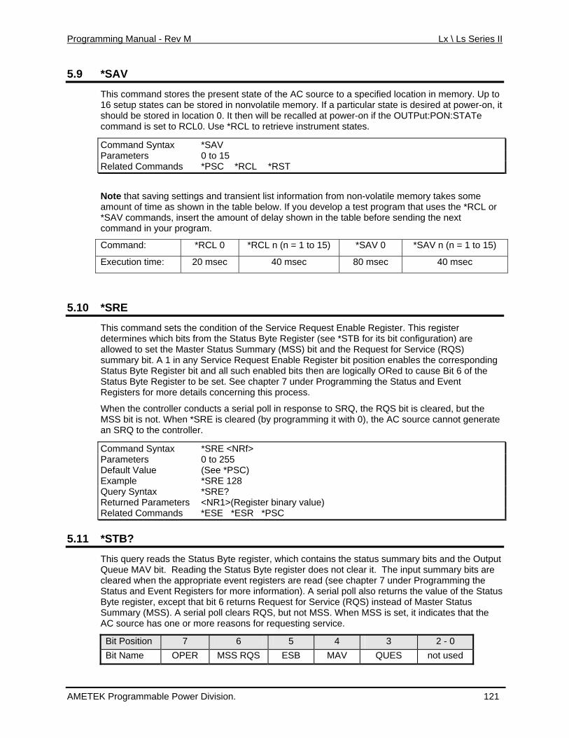
Programming Manual - Rev M Lx \ Ls Series II
5.9 *SAV
This command stores the present state of the AC source to a specified location in memory. Up to 16 setup states can be esired at power-on, it should be stored in location 0. It then will be recommand is set to RCL0. Use *RCL to retriev
Comm
stored in nonvolatile memory. If a particular state is dcalled at power-on if the OUTPut:PON:STATe
e instrument states.
and Syntax *SAV Parameters 0 to 15 Rela *RST ted Commands *PSC *RCL
ote that saving settings and transient list information from non-volatile memory takes some as show table below. If you develop a test program that uses the *RCL or
rt
Command: *RCL 0 *RCL n (n = 1 to 15) *SAV 0 *SAV n (n = 1 to 15)
Namount of time n in the *SAV comman the amods, inse unt of delay shown in the table before sending the next command in your program.
Execution time: 20 msec 40 msec 80 msec 40 msec
*SRE 5.10
This command sets the condition of the Ser B
vice Request Enable Register. This register ee *STB for its bit configuration) are nd the Request for Service (RQS)
it. A 1 in any Service Request Enable Register bit position enables the corresponding Register bit and all such enabled bits then are logically ORed to cause Bit 6 of the
hen *SRE is cleared (by programming it with 0), the AC source cannot generate
determines which bits from the Status yte Register (sallowed to set the Master Status Summary (MSS) bit asummary bStatus ByteStatus Byte Register to be set. See chapter 7 under Programming the Status and Event Registers for more details concerning this process.
When the controller conducts a serial poll in response to SRQ, the RQS bit is cleared, but the MSS bit is not. Wan SRQ to the controller.
Command Syntax *SRE <NRf> Parameters 0 to 255 Default Value (See *PSC) Example *SRE 128 Query Syntax *SRE? Returned Register binary value) Parameters <NR1>(Related Commands *ESE *ESR *PSC
5.11 *STB?
This query reads the Status Byte register, which contains the status summary bits and the Output The input summary bits are
Queue MAV bit. Reading the Status Byte register does not clear it. cleared when the appropriate event registers are read (see chapter 7 under Programming the Status and Event Registers for more information). A serial poll also returns the value of the StatusByte register, except that bit 6 returns Request for Service (RQS) instead of Master Status Summary (MSS). A serial poll clears RQS, but not MSS. When MSS is set, it indicates that the AC source has one or more reasons for requesting service.
Bit Position 7 6 5 4 3 2 - 0 Bit Name OPER MSS RQS ESB MAV QUES not used
AMETEK Programmable Power Division. 121
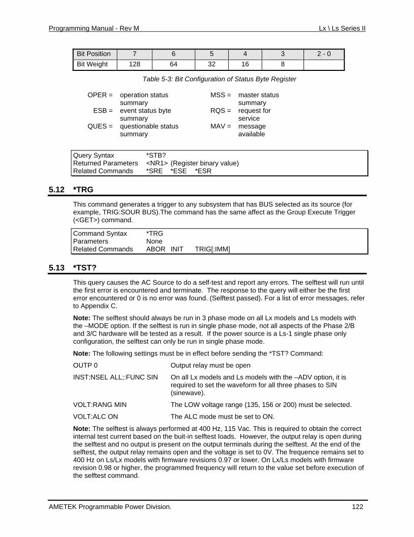
Programming Manual - Rev M Lx \ Ls Series II
Bit Position 7 6 5 4 3 2 - 0 Bit Weight 64 128 32 16 8
T ble 5-3 Bit Co
R = operation status summary
MSS = master status summary
Que
a : nfiguration of Status Byte Register
OPE
ESB = event status byte summary
RQS = request for service
QUES = questionable status MAV = message summary available
ry Syntax *STB? Returned Parameters <NR1> (Register binary value) Related Commands *SRE *ESE *ESR
5.12 R*T G
This command generates a trigger toexample, TRIG:SO US).Th
any subsystem that has BUS selected as its source (for UR B e command has the same affect as the Group Execute Trigger
ommand Syntax *TRG
(<GET>) command.
CParameters None Related Commands ABOR INIT TRIG[:IMM]
5.13 *TST?
This query causes the AC Source to do a self-test and report any errors. The selftest will run until the first error is encountered and terminate. The response to the query will either be the first error encountered or 0 is no error was found. (Selftest passed). For a list of error messages, refer to Appendix C.
Note: The selftest should always be run in 3 phase mode on all Lx models and Ls models with the –MODE option. If the selftest is run in single phase mode, not all aspects of the Phase 2/B and 3/C hardware will be tested as a result. If the power source is a Ls-1 single phase only configuration, the selftest can only be run in single phase mode.
Note: The following settings must be in effect before sending the *TST? Command:
OUTP 0 Output relay must be open
INST:NSEL ALL;:FUNC SIN On all Lx models and Ls models with the –ADV option, it is required to set the waveform for all three phases to SIN (sinewave).
VOLT:RANG MIN The LOW voltage range (135, 156 or 200) must be selected.
VOLT:ALC ON The ALC mode must be set to ON.
Note: The selftest is always performed at 400 Hz, 115 Vac. This is required to obtain the correct internal test current based on the buit-in selftest loads. However, the output relay is open during the selftest and no output is present on the output terminals during the selftest. At the end of the selftest, the output relay remains open and the voltage is set to 0V. The frequence remains set to 400 Hz on Ls/Lx models with firmware revisions 0.97 or lower. On Lx/Ls models with firmware revision 0.98 or higher, the programmed frequency will return to the value set before execution of the selftest command.
AMETEK Programmable Power Division. 122
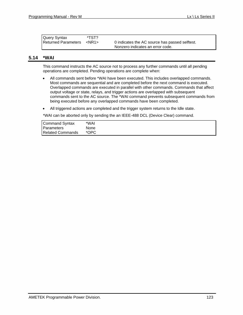
Programming Manual - Rev M Lx \ Ls Series II
Query Syntax *TST? Returned Parameters <NR1> 0 indicates the AC source has passed selftest. Nonzero indicates an error code.
5.14 *WAI
This command instructs the AC source not to process any further commands until all pending e when:
ve been executed. This includes overlapped commands. ted before the next command is executed.
ecuted in parallel with other commands. Commands that affect lays, and trigger actions are overlapped with subsequent source. The *WAI command prevents subsequent commands from y overlapped commands have been completed.
and the trigger system returns to the Idle state.
op rations are completed. Pending operations are complete
• All commands sent before *WAI haMost commands are sequential and are compleOverlapped commands are exoutput voltage or state, recommands sent to the ACbeing executed before an
• All triggered actions are completed
*WAI can be aborted only by sending the an IEEE-488 DCL (Device Clear) command.
Command Syntax *WAI Parameters None Related Commands *OPC
AMETEK Programmable Power Division. 123
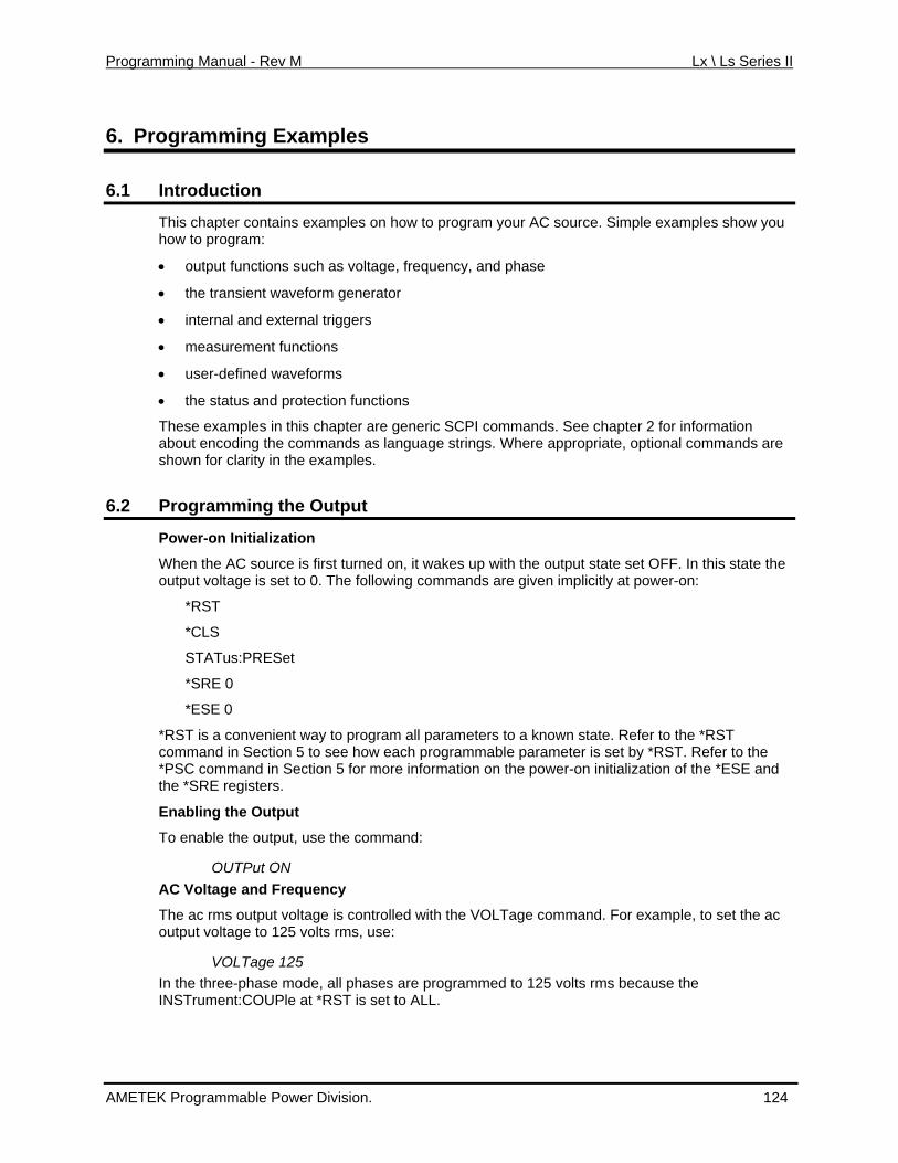
Programming Manual - Rev M Lx \ Ls Series II
6. Programming Examples
6.1 Introduction
This chapter contains examples on how to program your AC source. Simple examples show you
ers
• measurement functions
• the status and protection functions
6.2 the Output
how to
• output functions such as voltage, frequency, and phase
• the transient waveform generator
• internal and external trigg
program:
• user-defined waveforms
These examples in this chapter are generic SCPI commands. See chapter 2 for information about encoding the commands as language strings. Where appropriate, optional commands are shown for clarity in the examples.
Programming
Power-on Initialization
When the AC source is first turned on, it wakes up with the output state set OFF. In this state the
nvenient way to program all parameters to a known state. Refer to the *RST Section 5 to see how each programmable parameter is set by *RST. Refer to the
isters.
Enablin
d:
ut ON
rms, use:
In the three-phase mode, all phases are programmed to 125 volts rms because the INSTrument:COUPle at *RST is set to ALL.
output voltage is set to 0. The following commands are given implicitly at power-on:
*RST
*CLS
STATus:PRESet
*SRE 0
*ESE 0
*RST is a cocommand in *PSC command in Section 5 for more information on the power-on initialization of the *ESE and the *SRE reg
g the Output
To enable the output, use the comman
OUTPAC Voltage and Frequency
The ac rms output voltage is controlled with the VOLTage command. For example, to set the ac output voltage to 125 volts
VOLTage 125
AMETEK Programmable Power Division. 124
Programming Manual - Rev M Lx \ Ls Series II
The AC source can be programmed to turn off its output if the ac output voltage exceeds a preset peak voltage limit. This protection feature is implemented with the VOLTage:PROTection command as explained in chapter 4.
Maximum Voltage
The maximum rms output voltage that can be programmed can be queried with:
VOLTage? MAX The maximum voltage that the AC source can output is limited by the peak value of the
of o
ne waveform, the maximum ac voltage that can be prog
Note:
waveform. This is 425 V peak on all models. Since the user programs output voltage in unitsrms volts, the maximum value that can be programmed is dependent on the peak-to-rms rati(crest factor) of the selected waveform. For a si
rammed is 300 volts.
You cannot program a voltage that produces a higher volt-second on the output than a 300V rms sinewave.
Because voltage commands are coupled with the waveform shape command, changing voltages without changing the waveform shape or voltage offset may result in an error if the resulting peak
eds the maximum voltage rating of the AC source. Refer to "Coupled
taps on an
LTage:RANGe MIN | MAX | 150 | 300 et to MIN (or 150), the maximum rms voltage that can be programmed for a
this range that the maximum output current rating is m programmable voltage may be different,
depending on the waveform's voltage crest factor (peak-to-rms ratio).
VOLTage:RANGe command is coupled with the CURRent command. This t can be programmed at a given time depends on the resently operating. Refer to "Coupled Commands" for
more in
The output frequency is controlled with the FREQuency command. To set the output frequency to
de and frequency changes. te ramps or to protect sensitive loads. To set the voltage slew rate to
voltage amplitude exceCommands" for more information.
Voltage Ranges
The Lx\Ls Series has two voltage ranges4 that are controlled by a relay that switches output transformer. The command that controls the range is:
VOWhen the range is ssine waveshape is 150 volts, but it is only onavailable. For other waveshapes, the maximu
On the Lx Series, themeans that the maximum current limit thavoltage range setting in which the unit is p
formation.
Frequency
50 Hz, use:
FREQuency 50 Voltage and Frequency Slew Rates
Voltage Slew
The AC source has the ability to control the slew rate of ac amplituThis can be used to genera20 volts per second, use:
VOLTage:SLEW 20
4 Actual voltage range values may differ from those shown here based on Model (Lx or Ls) and configuration options (STD, -HV or –EVH). Use Limit or Max query to determine actual voltage range values.
AMETEK Programmable Power Division. 125
Programming Manual - Rev M Lx \ Ls Series II
At *RST the slew rate is set to INFinity, which means that ac voltage changes occur at the fastestpossible slew rate. The slew rate applies to programmed changes in ac output amplitude while the unit is o
perating in fixed mode. Amplitude changes made by the step, pulse, and list
e
nity, which means that frequency changes occur instantaneously. The frequency slew rate applies to programmed changes in frequency while the
d mode. Frequency changes made by the step, pulse, and list transients are controlled by the same rules that apply to all other functions that are subject to transient
6.2.1 W v apes
transients are controlled by the same rules that apply to all other functions that are subject to transient control. See "Programming Transient Outputs".
Output voltage changes caused by the OUTPut:STATe command, by a protection feature disabling the output, or as a result of load changes are not subject to this slew rate control.
Frequency Slew
The AC source also has the ability to control the slew rate of frequency changes. To set thfrequency slew rate to 30 Hz per second, use:
FREQuency:SLEW 30 At *RST the slew rate is set to INFi
unit is operating in fixe
control. See "Programming Transient Outputs".
a eform Sh
At RST, the * AC source supplies a sine waveform, but other shapes can be selected. There are built-in tables for sine, square and clipped sine waveforms. In addition, the user can define
hapes by creating a 1024 point table of amplitudes for a single cycle.
the following examples, the FUNCtion[:SHAPe] command selects the output
HAPe SQUare Clipped
To select a clipped sine waveform use:
ge of the peak amplitude at which clipping occurs.
The clipping level can also be specified in terms of the percent total harmonic distortion in the clipped sine waveform by adding a THD suffix to the command. For example;
10% distortion.
TA] command to send the list of 1024 amplitude points. The med
ne DISTORTION
TRACe:DATA DISTORTION, n1, n2, n3, ..., n1024
arbitrary waves
As shown in waveform.
Square Waveform
To select the square output waveform, use:
FUNCtion:S Waveform
FUNCtion:SHAPe CSINusoid To set the clipping level to 50%, use:
FUNCtion:SHAPe:CSINusoid 50 The clipping level is the percenta
FUNCtion:SHAPe:CSINusoid 10 THD
sets the clipping level so that the clipped sine has
User-Defined Waveform
To create a user-defined waveform, use TRACe:DEFine command to create a name for the waveform, then use the TRACe[:DAwaveform can then be selected using the FUNCtion command. For example, a waveform na"Distortion" can be created with:
TRACe:DEFi
AMETEK Programmable Power Division. 126
Programming Manual - Rev M Lx \ Ls Series II
where n1 ... n1024 are the data points that define the relative amplitudes of exactly one cyclthe wavefor
e of m. The first data point defines the amplitude that will be output at 0 degrees phase
format that ent and ensures that the correct ac rms voltage is output when the
waveform is selected. When queried, trace data is returned as normalized values in the range of ta is stored in nonvolatile memory and is retained when input power is removed. fined waveforms may be created and stored. See section 6.10 for programming
Because waveform shape commands are coupled with the voltage commands, changing waveforms without changing the programmed voltage may result in an error if the resulting peak
e rating of the AC source. Refer to "Coupled
6.2.2 I
reference.
Data points can be in any arbitrary units. The AC source scales the data to an internalremoves the dc compon
±1. Waveform daUp to 50 user deexample.
voltage amplitude exceeds the maximum voltagCommands" for more information.
ndividual Phases
The following functions can be controlled separately in each phase:
• PHASe
Selecting a Phase
h output phase or phases receive commands in the three-phase
nds
n select the desired output to receive the command with INSTrument:NSELect. For
exampl
INSTrument:NSELect 2 are sent, all subsequent voltage commands will go to output phase 2, and all measurement queries will return readings from output phase 2.
t.
• VOLTage
• CURRent
• MEASure
• FETCh
• CALibrate
Two commands determine whicmode. These are:
INSTrument:COUPle ALL | NONE
INSTrument:NSELect <n> The *RST setting for INSTrument:COUPle is ALL. This setting causes programming commato be sent to all output phases simultaneously.
To send a programming command to only one of the output phases, set INSTrument:COUPle toNONE, the
e, when the commands
INSTrument:COUPle NONE
The INSTrument:COUPle command has no effect on queries. In the three-phase mode, queries are always directed to the output selected by INSTrument:NSELec
Programming the Output Phase
You can control the phase of the ac voltage waveform relative to an internal reference with:
PHASe <n>
AMETEK Programmable Power Division. 127
Programming Manual - Rev M Lx \ Ls Series II
which sets the phase in degrees. If <n> is positive, the voltage waveform leads the internal
UPle Se command - it always controls the output selected by
6.2.3 C
reference.
The PHASe command sets the relative phase of each of the outputs. The INSTrument:COsetting is ignored by the PHAINSTrument:NSELect.
urrent Limit
All models have a programmable rms current limit function. The command to set this limit is:
If the load attempts to draw more current than the programmed limit, the output voltage is imit. Since the rms detection involves a filter time utput cycle, the response time of the rms current limit
output voltage is reduced, its waveform is preserved (the output ped).
The ed. This pro ti mand as explained in c
Note: The U that the
CURRent <n> where <n> is the rms current limit in amperes.
reduced to keep the rms current within the lconstant that is long compared to a single ois not instantaneous. When thewaveform is attenuated, not clip
AC source can be programmed to turn off its output if the rms current limit is reachtec on feature is implemented with the CURRent:PROTection:STATe comhapter 3.
C RRent command is coupled with the VOLTage:RANGe.This means maximum current limit that can be programmed at a given timerange setting in which the unit is presently operating. Refer to "Coupled Commands" for
depends on the voltage
mo inre formation.
6.3 Co l up ed Commands
This section describes how to avoid programming errors that may be caused because of the error checking done for coupled commands such as VOLTage:LEVel and FUNCtion:SHAPe.
SHAPe commands are the output transient com s that control s t transient is initiated (rea eceive a trigg ximum peak output voltage incl y combinatiotransient.
URRent:LEVeProgramming the curren at is greater than the maximum allowed on the pres rogrammed v
rated because the CURRent command is requesting a current limit value allowed on that voltage range.
the
VOLTage:RANGe 150
CURRent 10
Commands that are coupled to the VOLTage and mand tep, pulse and list generation. When an outpudy to r er), the error checking that takes place for ma
udes an n of voltage, voltage offset, or function shape that can occur during the
C l and VOLTage:RANGe t limit by itself to a value th
ently p oltage range causes an error. If the commands
VOLTage:RANGe 300
CURRent 10 are sent, an error will be genethat is outside the maximum
Programming the VOLTage:RANGe by itself causes the programmed current limit to be set tomaximum for the given range if it had previously been higher than the maximum setting for the new range. If the commands
AMETEK Programmable Power Division. 128
Programming Manual - Rev M Lx \ Ls Series II
VOLTage:RANGe 300 are sent, no error will be generated because the second VOLTage:RANGe command automatically sets the programmed current limit to 5, which is the maximum value for the
program message unit can be done
are sent, no error will be generated because the combined current limit and voltage range specified on the second line are within the output ratings of above models.
6.4 Programming Output Transients
programmed voltage range.
Programming both the current and the voltage range in one in any order and will not cause an error if the final combination specifies a valid current limit for the indicated range. If the commands
VOLTage:RANGe 300
CURRent 10;:VOLTage:RANGe 150
Output transients are used to:
• Synchronize output changes with a particular phase of the voltage waveform. • Synchronize output changes with internal or external trigger signals. • Simulate surge, sag, and dropout conditions with precise control of duration and phase. • Create complex, multi-level sequences of output changes. • Create output changes that have rapid or precise timing requirements.
The following AC source functions are subject to transient control:
• AC output voltage • Frequency • Phase • Waveform shape • AC voltage slew rate • Frequency slew rate
The following transient modes can be generated:
Step generates a single triggered output change.
Pulse generates an output change which returns to its original state after some time period.
List generates a sequence of output changes, each with an associated dwell time or paced by triggers.
Fixed turns off the transient functions, which means that only the IMMediate values are used as the data source for a particular function.
At *RST all functions are set t nctions.
6.4.1 Transient System Model
o FIXed, which turns off the transient fu
Figure 6-1 is a model of the transient system. The figure shows the transient modes and the rigger is received in step or pulse modes, source of the data that generates each mode. When a t
the triggered functions are set from their IMMediate to their TRIGgered value.
AMETEK Programmable Power Division. 129
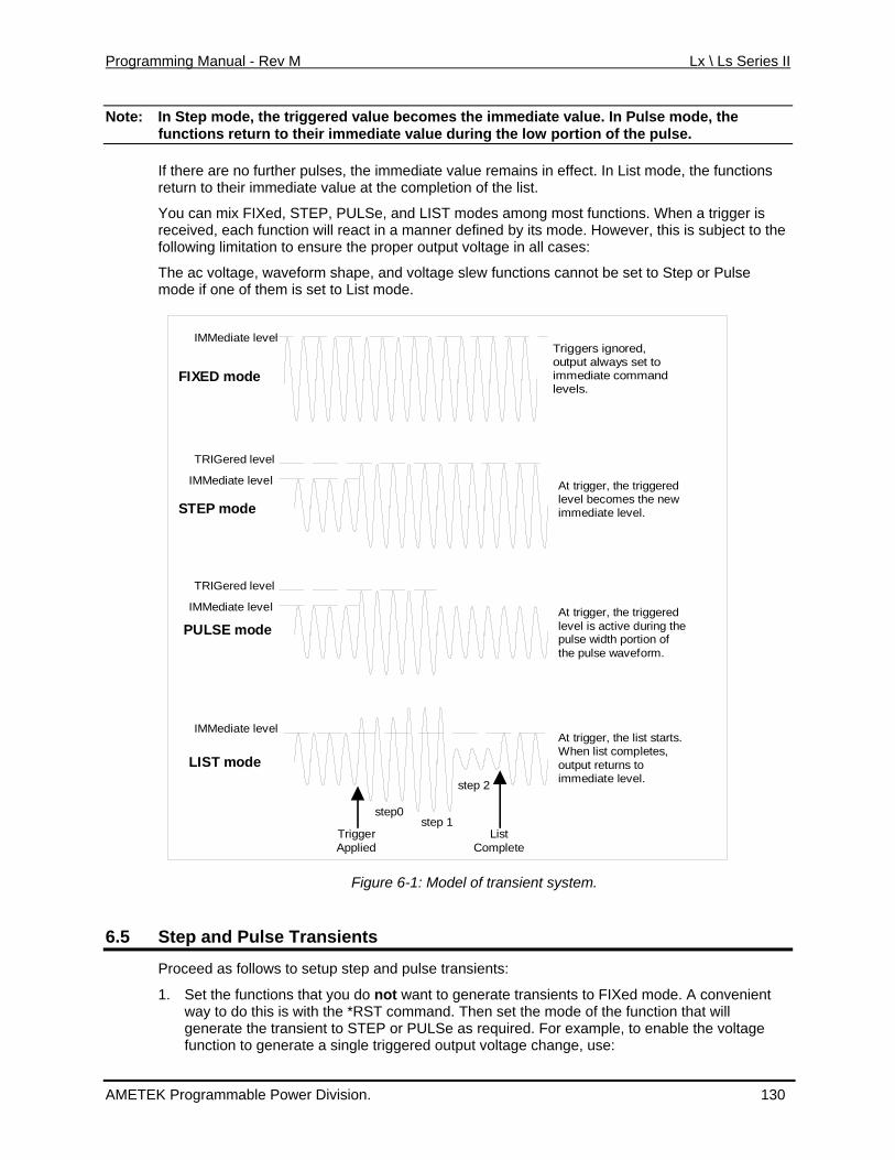
Programming Manual - Rev M Lx \ Ls Series II
Note: In Step mode, the triggered value becomes the immediate value. In Pulse mode, the functions return to their immediate value during the low portion of the pulse.
If there are no further pulses, the immediate value remains in effect. In List mode, the functions return to their immediate value at the completion of the list.
You can mix FIXed, STEP, PULSe, and LIST modes among most functions. When a trigger is received, each function will react in a manner defined by its mode. However, this is subject to the
The s cannot be set to Step or Pulse mode if
following limitation to ensure the proper output voltage in all cases:
ac voltage, waveform shape, and voltage slew functionone of them is set to List mode.
IMMediate level
IXED mode
Triggers ignored,output always set to
F immediate commandlevels.
TRIGered level
IMMediate level At trigger, the triggeredlevel becomes the new
STEP mode immediate level.
TRIGered level
IMMediate level At trigger, the triggeredlevel is active during thePULpulse width portion ofthe pulse waveform.
SE mode
IMMediate level
LIST mode
TriggeApplie
At trigger, the list starts.When list completes,
r Listd Complete
step0step 1
step 2
output returns toimmediate level.
Fig
6.5
ure 6-1: Model of transient system.
Step and Pulse Transients
Proceed as follows to setup step and pulse transients:
1. Set the functions that you do not want to generate transients to FIXed mode. A convenient way to do this is with the *RST command. Then set the mode of the function that will generate the transient to STEP or PULSe as required. For example, to enable the voltage function to generate a single triggered output voltage change, use:
AMETEK Programmable Power Division. 130
Programming Manual - Rev M Lx \ Ls Series II
*RST
STEP
VOLTage:TRIGger 135 l
CYCle 50 specifies a duty cycle of 50%
• P specifies a pulse width of .5 seconds (not necessary in this case ce a duty cycle has already been specified)
r
6. le the transient system indefinitely use:
Exa
The following example programs a voltage dropout fodropout degrees phase) and is triggere
*RSVOFREOUVOLT:MODE PULS VOLT:T t (triggered level) PUL Set pulse width for 2 periods TRIG:SOUR BUS TRIG:S ronize triggers to internal phase reference TRIG:S internal phase reference point to 90 degrees
VOLTage:MODE2. Set the triggered level of the function that will generate the transient. For example, if the
previously programmed voltage function is going to step the output voltage amplitude to 135 volts upon receipt of a trigger, use:
3. Select the trigger source that will generate the trigger. For example, to select the externaTrigger In1 SMA connector as the trigger source, use:
TRIGger:TRANsient:SOURce EXTernal Trigger sources are discussed in detail under "Triggering Output Changes".
4. Only perform this step if you have selected PULSE as the transient mode in Step 1. Specify the pulse count, the pulse period, and then either the duty cycle or the pulse width using the following commands:
• PULSe:COUNt 1 specifies 1 output pulse
• PULSe:PERiod 1 specifies a pulse period of 1 second
• PULSe:D
ULSe:WIDTh .5 sin
5. Initiate the transient trigger system to enable it to receive a trigger. To enable the triggesystem for one transient event use:
INITiate:IMMediate:SEQuence1 To enab
INITiate:CONTinuous:SEQuence1 ON Trigger the transient. This is described in detail under "Triggering Output Changes".
mple
r 2 cycles of a 120 volt, 60 Hz output. The begins at the positive peak of the output voltage waveform (90d by IEEE-488 bus trigger.
T Begin at power-on state LT 120 Set initial output voltage (immediate-level) Q 60 Set initial output frequency
TP ON Enable the output Enable output to generate pulses when triggered
RIG 0 Set the voltage dropouS:WIDT .03333
Respond to IEEE-488 bus triggers YNC:SOUR PHAS SynchYNC:PHAS 90 Sets
INIT:SEQ1 Set to Wait-for-trigger state <device trigger> Send the IEEE-488 bus trigger
AMETEK Programmable Power Division. 131
Programming Manual - Rev M Lx \ Ls Series II
6.6 List Transients
List mode lets you generate complex sequences of output changes with rapid, precise timing, whi rticipate in
You can program up to 100 settings (or points) in the list, the time interval (dwell) that each setting is maintained, the number of times that the list will be executed, and how the settings change in response to triggers.
All l list
List Therefore, each of the up to 100 list points has an associated dwell time, which specifies the time (in seconds) that the output remain at that setting before moving on to the next setting.
The es:
1.
2. Program the list of output values for each function. The list commands take a comma- order in which the arguments are given determines the
r example, to cycle the voltage through a
y include the following values:
r points, or an error will occur when the ion is when a list has
only one item or point. In this case the single-item list is treated as if it had the same number ues being equal to the one item. For example:
ecified in seconds. For example, to specify five
, use:
utput points. If a dwell list has only , that value wil d to all points in the output list.
ch may be synchronized with internal or external signals. Each function that can paoutput transients can also have an associated list of values that specify its output at each list point.
ist point data is stored in nonvolatile memory. This means that the programmed data for anyfunction will be retained when the AC source is turned off.
s are paced by a separate list of dwell times which define the duration of each output setting.
following procedure shows how to generate a simple list of voltage and frequency chang
Set the mode of each function that will participate in the output sequence to LIST. For example:
VOLTage:MODE LIST
FREQuency:MODE LIST
separated list of arguments. Thesequence in which the values will be output. Fosequence that includes nominal line, high line, and low line, a list may include the following values:
LIST:VOLTage 120, 132, 108, 120, 132, 108, 120, 132, 108 You can specify lists for more than one function. For example, to synchronize the previous voltage list with another list that varies the output frequency from nominal, to high, to low, thelists ma
LIST:VOLTage 120, 132, 108, 120, 132, 108, 120, 132, 108
LIST:FREQuency 60, 60, 60, 63, 63, 63, 57, 57, 57 All lists must have the same number of data values otransient system that starts the sequence is later initiated. The except
of points as the other lists, with all val
LIST:VOLTage 110, 120, 130;FREQuency 60 is the same as:
LIST:VOLTage 110, 120, 130
LIST:FREQuency 60, 60, 60 3. Determine the time interval that the output remains at each level or point in the list before it
advances to the next point. The time is spdwell intervals
LIST:DWELl 1, 1.5, 2, 2.5, 3 The number of dwell points must equal the number of oone value l be applie
AMETEK Programmable Power Division. 132
Programming Manual - Rev M Lx \ Ls Series II
4. Determine the number of times the list is repeated before it completes. For example, to repeat a list 10 times use:
list repeat indefinitely. At *RST, the count is set to 1.
5. Determines how the list sequencing responds to triggers. For a closely controlled sequence of output levels, you can use a dwell-paced list. To cause the list to be paced by dwell time use:
LIST:STEP AUTO As each dwell time elapses, the next point is immediately output. This is the *RST setting.
If you need the output to closely follow asynchronous events, then a trigger-paced list is more appropriate. In a trigger-paced list, the list advances one point for each trigger received. To enable trigger-paced lists use:
LIST:STEP ONCE The dwell time associated with each point determines the minimum time that the output remains at that point. If a trigger is received before the previous dwell time completes, the trigger is ignored. Therefore, to ensure that no triggers are lost, program the dwell time to zero.
6. Use the transient trigger system to trigger the list. This is described in detail under "Triggering Output Changes" (Section 6.7).
6.7 Triggering Output Changes
LIST:COUNt 10 Entering INFinity makes the
The AC source has two independent trigger systems. One is used for generating output changes, and the other is used for triggering measurements. This section describes the output trigger system. The measurement trigger system is described under "Triggering Measurements".
The basic components of both systems are the same, but the transient trigger system has additional delay and phase synchronization features that the measurement trigger system does not have.
The following transient trigger sources can be selected:
IMMediate generates a trigger when the trigger system is initiated.
BUS selects IEEE-488 bus triggers.
EXTernal selects the external Trigger In1 SMA connector.
6.7.1 SCPI Triggering Nomenclature
In SCPI terms, trigger syste one trigger system exists, they are differentiated by naming them SEQuence1, SEQuence2, ... etc. In the AC source,
EQuence1 is the transient trigger system, SEQuence2 is the phase synchronization trigger system, and SEQuence3 is the measurement trigger system.
criptive names for these sequences. These aliases
ms are called sequences. When more than
S
The AC source uses aliases with more descan be used instead of the sequence forms.
Sequence Form Alias
SEQuence1 TRANsient
SEQuence2 SYNChronize
SEQuence3 ACQuire
AMETEK Programmable Power Division. 133
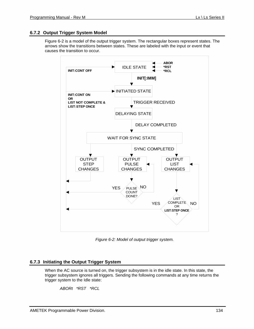
Programming Manual - Rev M Lx \ Ls Series II
6.7.2 Output Trigger System Model
Figure 6-2 is a model of the output trigger system. The rectangular boxes represent states. The arrows show the transitions between states. These are labeled with the input or event that causes the transition to occur.
IDLE STATE
INITIATED STATE
DELAYING STATE
WAIT FOR SYNC STATE
OUTPUTE
ANGESPULS
CH
OUTPUTSTEP
CHANGES
OUTPUTLIST
CHANGES
PULSECOUNTDONE?
LIST
?
COMPLETEOR
LIST:STEP ONCE
YES NO
NOYES
SYNC COMPLETED
TRIGGER RECEIVED
IT[:IMM]
DELAY COMPLETED
IN
ABOR*RST*RCLINIT:CONT OFF
INIT:CONT ONORLIST NOT COMPLETE &LIST:STEP ONCE
Figure 6-2: Model of output trigger system.
6.7.3 Initiatin g the Output Trigger System
When the AC source is turned on, the trigger subsystem is in the idle state. In this state, the trigger subsystem ignores all triggers. Sending the following commands at any time returns the trigger system to the Idle state:
ABORt *RST *RCL
AMETEK Programmable Power Division. 134
Programming Manual - Rev M Lx \ Ls Series II
The INITiate commands move the trigger system from the Idle state to the Initiated state. This enables the AC source to receive triggers. To initiate for a single triggered action, use:
he trigger system will return to the Idle state.
t having to send an initiate command for each trigger,
r
E TRANsient, ON The SEQuence2 (or SYNChronize) trigger sequence does not have an INITiate command. It is always
6.7.4 S
INITiate:IMMediate:SEQuence1 or
INITiate:IMMediate:NAME TRANsient After a trigger is received and the action completes, tThus it will be necessary to initiate the system each time a triggered action is desired. To keep a trigger system initiated for multiple actions withou
use:
INITiate:CONTinuous:SEQuence1 ON o
INITiate:CONTinuous:NAM
initiated.
electing the Output Trigger Source
The trigger system is waiting for a trigger signal intrigger, you must select a trigger source. To selec
the Initiated state. Before you generate a t the external Trigger In1 SMA as the source,
use:
TRIGger:TRANsient:SOURce EXTernal
riggers (group execute trigger, device trigger, or *TRG command), use:
ient:SOURce BUS
that is always true, use:
or
er:TRANsient:SOURce IMMediate
The immediate source can be combined with INITiate:CONTinuous:SEQuence1 ON to generate repetitive output transients. A transition from the Initiated state to the Delay state is made when
6.7.5 Specify
TRIGger:SEQuence1:SOURce EXTernal or
To select IEEE-488 bus t
TRIGger:SEQuence1:SOURce BUS or
TRIGger:TRANs
To select a trigger source
TRIGger:SEQuence1:SOURce IMMediate
TRIGg
the trigger signal is received.
ing a Trigger Delay
A time delay can be programmed between the receipt of the trigger signal and the start of the output t , which means that there is no delay. To program
which sets a delay time of 10 milliseconds. A trigger delay can only be programmed for rammed trigger delay has elapsed, the
e Wait-for-sync state.
ransient. At *RST the trigger delay is set to 0 a delay, use:
TRIGger:SEQuence1:DELay .01 or
TRIGger:TRANsient:DELay .01
SEQuence1 (or TRANsient) triggers. When the progtrigger system transitions from the Delay state to th
AMETEK Programmable Power Division. 135
Programming Manual - Rev M Lx \ Ls Series II
6.7.6 Synchronizing Output Changes to a Reference Phase Angle
An output transient normally occurs immediately when the trigger signal is received, or after thdelay has expired if a trigger delay has been set. For some applications it is desirable that the transient is synchronized with a particular phase of the output waveform
e
such as the zero
e, you
To s
TRIGger:SYNChronize:PHASe 90 se angle of the internal phase reference as the point where the
transient begins.
6.7.7 Generating
crossing point or the positive peak.
To synchronize the start of a transient with a particular phase of the internal phase referencmust select PHASE as the trigger source. Use:
TRIGger:SEQuence2:SOURce PHASe or
TRIGger:SYNChronize:SOURce PHASe elect the desired phase, use:
TRIGger:SEQuence2:PHASe 90 or
which specifies the 90 degree pha
To turn off transient phase synchronization, use:
TRIGger:SYNChronous:SOURce IMMediate When IMMediate is selected, the trigger system transitions through the Delaying and Wait-for-sync states and goes directly to the Output state. This is the parameter selected at *RST.
Triggers
Profollo
•
a high-to-low transition to the Trig In1 SMA connector.
Continuous Triggers
INITiate:CONTinuous:SEQuence1 ON When the trigger system enters the Output Change state upon receipt of a trigger (see Figure
r programmed trigger levels. When the triggered
6.7.8 Specify t Point
viding that you have specified the appropriate trigger source, you can generate triggers as ws:
Single Triggers
By sending one of the following over the IEEE-488:
• TRIGger:IMMediate
• *TRG
• a group execute trigger
• By applying a signal with
• By sending the following commands over the IEEE-488:
TRIGger:SEQuence1:SOURce IMMediate
6-2), the triggered functions are set to theiactions are completed, the trigger system returns to the Idle state.
ing a Dwell Time for Each Lis
Each voltage and current list point has an associated dwell time specified by:
LIST:DWELl <n> {,<n>}
AMETEK Programmable Power Division. 136
Programming Manual - Rev M Lx \ Ls Series II
where <n> specifies the dwell time in seconds. The number of dwell points must equal the ed to all points in
point in re the list advances to the next point. Only an ABO out of the Dwelling state.
At the end of the dwell interval, the transition to the next state depends on whether or not the list ing and the state of the LIST:STEP command (see Figure 6-2).
r.
.
6.8 Making
number of output points. If a dwell list has only one value, that value will be applithe output list. After each new output level or point is programmed, the output remains at that
the list for the programmed dwell interval befoRt command can transfer the system
has completed its sequenc
• If the list is completed, the trigger system returns to the Idle state.
• If the list is not completed, then the system reacts as follows:
LIST:STEP ONCE programs the trigger system to return to the Initiated state to wait for thenext trigge
LIST:STEP AUTO programs the trigger system to immediately execute the next list point
Measurements
The AC source has the c rn a number of current, voltage, and powmeasurements. When the AC source is turned on, it is continuously sampling th
apability to retu er e instantaneous
output voltage and current for several output cycles and writing the results into a buffer. The urrent data points.
ed
commands to immediately start acquiring new voltage and current data, and return measurement calculations from this dateas programming.
• Use om the buffer. Then use the rieved by the acq ize the data acquisition
Note of the query, there is a corresponding query that begins with the
buffer holds 4096 voltage and c
The AC source uses the data from the voltage and current buffer to calculate the requestmeasurement information. Data in the voltage and current buffers is always re-acquired for subsequent measurement requests. There are two ways to make measurements:
• Use the MEASurea as soon as the buffer is full. This is the
iest way to make measurements, since it requires no explicit trigger
an acquisition trigger to acquire the voltage and current data frFETCh commands to return calculations from the data that was retuisition trigger. This method gives you the flexibility to synchron an external signal. FETCh commands do not trigger the acquiswith ition of new measurement
data, but they can be used to return many different calculations from the data that was retrieved by the acquisition trigger.
Making triggered measurements with the acquisition trigger system is discussed under "Triggering Measurements".
For each MEASure form header FETCh. FETCh queries perform the same calculation as their MEASure counte ata acquired by an explicit trigger d are used.
rparts, but do not cause new data to be acquired. Dor a previously programmed MEASure comman
6.8.1 Voltage and Current Measurements
To read the sum of ac and dc components of the rms voltage or current, use:
MEASure:VOLTage:ACDC? or
MEASure:CURRent:ACDC? To measure the dc voltage or current components, use:
MEASure:VOLTage:DC? or
AMETEK Programmable Power Division. 137
Programming Manual - Rev M Lx \ Ls Series II
MEASure:CURRent:DC? To measure the maximum current amplitude and the current crest factor, use:
MEASure:CURRent:AMPLitude:MAXimum?
MEASure:CURRent:CREStfactor?
ower Measurements 6.8.2 P
The MEASure and FETCh queries can return real, apparent, and reactive power measurements as well as dc power and power factor using the following commands:
MEASure:POWer:AC:APParent? measures the ac component of apparent power in VA
MEASu measures the reactive power
MEASu measures the in-phase component of power in watts
MEASu returns the output power factor
MEASu measures the total real power being sourced
6.8.3 H
re:POWer:AC:REACtive?
re:POWer:AC:REAL?
re:POWer:AC:PFACtor?
re:POWer:AC:TOTal?
MEASure:POWer:DC? measures the dc component of power
armonic Measurements
The MEASure and FETCh queries can return the amplitude and phase of up to the 50th harmonic of voltage and current. They can also return the total harmonic distortion in the output voltage or current. For example, to return readings for an individual harmonic component, use the followin
RMonic:AMPLitude? <harmonic number>
of output voltage. Queries sent with an a nt of 0 return t of 1 indicates the fundamental freq dicates th on.
The m harmonic easurement ban hich is 16 k at has a frequency greater than 16 kHz. To return all the harmonic components with a single query, use the following commands:
MEASure:ARRay:CURRent:HARMonic:AMPLitude?
MEASure:ARRay:CURRent:HARMonic:PHASe?
MEASure:ARRay:VOLTage:HARMonic:AMPLitude?
MEASure:ARRay:VOLTage:HARMonic:PHASe? These queries always return 51 data values, from the dc component up to the 50th harmonic. Any harmonics that represent frequencies greater than 16 kHz are returned as the value 0. To return the percentage of total harmonic distortion in the output voltage or current, use the following commands:
MEASure:CURRent:HARMonic:THD?
MEASure:VOLTage:HARMonic:THD?
g commands:
MEASure:CURRent:HA
MEASure:CURRent:HARMonic:PHASe? <harmonic number>
MEASure:VOLTage:HARMonic:AMPLitude? <harmonic number>
ber> MEASure:VOLTage:HARMonic:PHASe? <harmonic numHarmonic numbers are related to the programmed frequency
rgume the dc component. An argumenuency, 2 in e second harmonic, 3 indicates the third, and so
maximu component that can be read is limited by the fundamental mdwidth, w Hz. An error is generated if a query is sent for a harmonic th
AMETEK Programmable Power Division. 138
Programming Manual - Rev M Lx \ Ls Series II
6.8.4 Simultaneous Output Phase Measurements
You can return simultaneous measurements from all output phases of the source in the three phase mode using the FETCh query. Unlike MEASure queries, FETCh queries do not trigger theacquisition of new data when they are executed. First, you must initiate the measurement trigger system and generate
a measurement trigger as explained in the following section "Triggering Measurements". When the measurement data has been acquired by the voltage and current data buffers for each output phase, use INSTrument:NSELect to select each phase, and FETCh to return the specified measurement data. The following commands return rms voltage:
INSTrument:NSELect 1
INSTrument:NSELect 3
FETCh:VOLTage:AC?
6.8.5 Returning Voltage and Current Data From the Data Buffer
FETCh:VOLTage:AC?
INSTrument:NSELect 2
FETCh:VOLTage:AC?
The MEASure and FETCh queries can also return all 4096 data values of the instantaneous voltage and current buffers. These are:
MEASure:ARRay:CURRent?
MEASure:ARRay:VOLTage?
6.8.6 Triggering Measurements
You can use the data acquisition trigger system to synchronize the timing of the voltage and current data acquisition with an external trigger source. Then use the FETCh commands to return different calculations from the data acquired by the measurement trigger.
The following measurement trigger sources can be selected:
BUS se
EXTernal selects the external Trigger In1 SMA connector.
e Trigger Out1 SMA connector.
lects IEEE-488 bus triggers.
TTLTrg selects the signal driving th
AMETEK Programmable Power Division. 139
Programming Manual - Rev M Lx \ Ls Series II
6.8.7 SCPI Measurement Triggering Nomenclature
As previously explained under "Triggering Output Changes", the AC source uses the following er system. This alias can be used instead of sequence name and alias for the measurement trigg
the sequence form.
Sequence Form Alias
SEQuence3 ACQuire
6.8.8 Measurement Trigger System Model
Figure 6-3 is a model of the measurement trigger system. The rectangular boxes represent states. The arrows show the transitions between states. These are labeled with the input or event that causes the transition to occur.
IDLE STATE
INITIATED STATE
DATA ACQUISITION
IN
TRIGGER RECEIVED
IT[:IMM]
ABOR*RST*RCL
6.8.9 Initiating the Measurement Trigger System
Figure 6-3: Model of Measurement triggers.
When the AC source is turned on, the trigger system is in the idle state. In this state, the trigger system ignores all triggers. Sending the following commands at any time returns the trigger system to the Idle state:
ABORt *RST *RCL The INITiate commands move the trigger system from the Idle state to the Initiated state. This enables the AC source to receive triggers. To initiate for a measurement trigger, use:
INITiate:IMMediate:SEQuence3 or
mpletes, the trigger system will return to the y to initiate the system each time a triggered acquisition is
INITiate:IMMediate:NAME ACQuire After a trigger is received and the data acquisition coIdle state. Thus it will be necessardesired.
AMETEK Programmable Power Division. 140
Programming Manual - Rev M Lx \ Ls Series II
Note: riggers continuously. Otherwise, the measurement data You cannot initiate measurement tin the data buffer would continuously be overwritten by each triggered measurement.
6.8.10 Selecting the Measurement Trigger Source
The trigger system is waiting for a trigger signal in the Initiated state. Before you generate a er source. To select the external Trigger In1 SMA as the source,
To select IEEE-488 bus triggers (group execute trigger, device trigger, or *TRG command), use:
6.8.11 Measurement Triggers
trigger, you must select a trigguse:
TRIGger:SEQuence3:SOURce EXTernal or
TRIGger:ACQuire:SOURce EXTernal
TRIGger:SEQuence3:SOURce BUS or
TRIGger:ACQuire:SOURce BUS To select the signal driving the Trigger Out1 SMA connector, use:
TRIGger:SEQuence3:SOURce TTLTrg or
TRIGger:ACQuire:SOURce TTLTrg
Generating
Providing that you have specified the appropriatefollows:
trigger source, you can generate triggers as
h-to-low transition to the Trig In1 SMA connector.
ent that causes the Trig Out1 SMA connector to output a pulse.
6.8.12
• By sending one of the following over the IEEE-488:
• TRIGger:SEQuence3:IMMediate
• TRIGger:ACQuire:IMMediate
• *TRG
• a group execute trigger
• By applying a signal with a hig
• By generating an output transi
Using the DFI Output to Indicate Error Conditions
The Discrete Fault Indicator output on the rear of the Lx\Ls Series unit can be used to provide a the DFI
up internally removed by removing jumper W1 on the
ctive high so a logic 1 state indicates a fault
e following command:
control or status signal to an external device. The following example illustrates the use ofoutput to signal a current limit fault condition.
The DFI output is the floating collector and emitter of an opto isolator. It is pulledusing a pull up resistor to 5Vdc. The pull up can be 7004-716 range/relay board. The DFI output is acondition.
The OCP detector has be to activated by sending th
CURR:PROT:STATE ON
To enable the DFI circuit, send:
AMETEK Programmable Power Division. 141
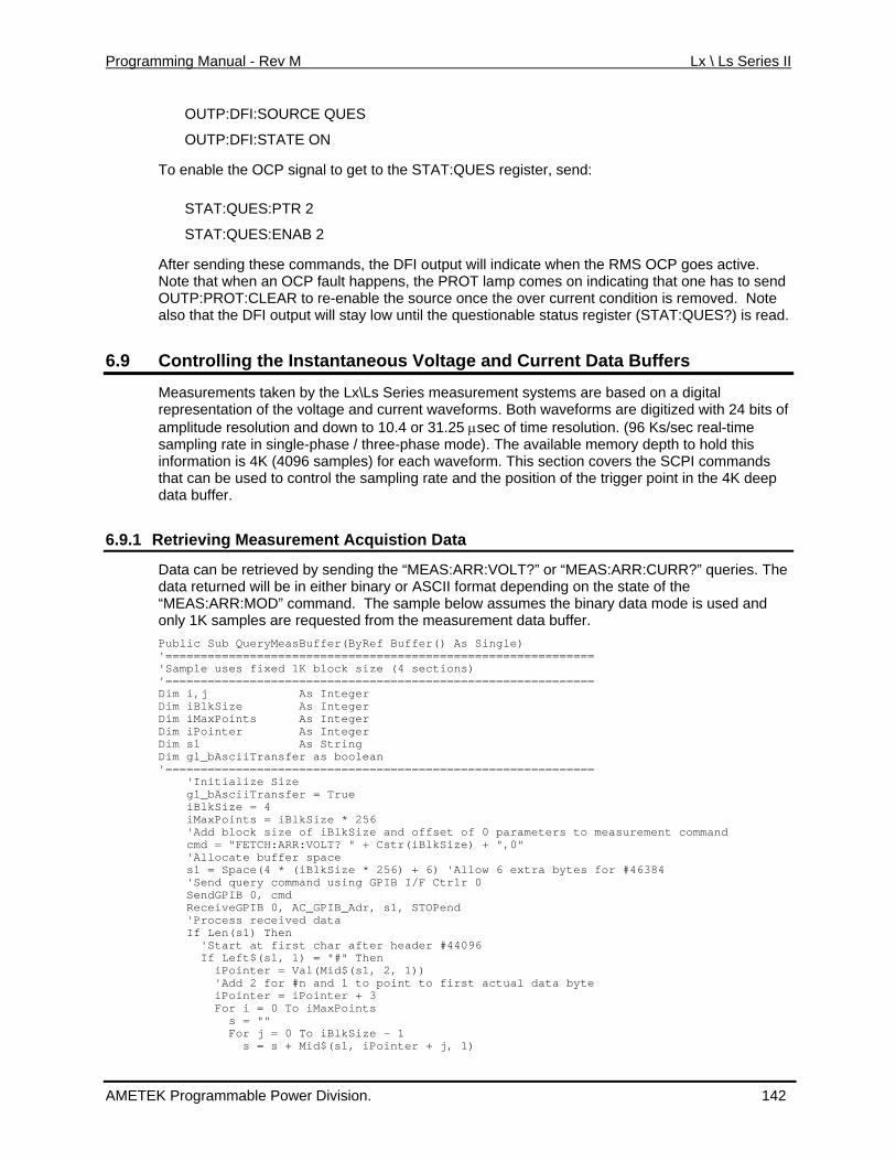
Programming Manual - Rev M Lx \ Ls Series II
OUTP:DFI:SOURCE QUES
OUTP:DFI:STATE ON
To enable the OCP signal to get to the STAT:QUES register, send:
STAT:QUES:PTR 2
After sending these commands, the DFI output will indicate when the RMS OCP goes active. hat one has to send
d.
6.9
STAT:QUES:ENAB 2
Note that when an OCP fault happens, the PROT lamp comes on indicating tOUTP:PROT:CLEAR to re-enable the source once the over current condition is removed. Note also that the DFI output will stay low until the questionable status register (STAT:QUES?) is rea
Controlling the Instantaneous Voltage and Current Data Buffers
Measurements taken by the Lx\Ls Series measurement systems afor
re based on a digital ms are digitized with 24 bits of
mory depth to hold this es) for each waveform. This section covers the SCPI commands sampling rate and the position of the trigger point in the 4K deep
6.9.1 R
representation of the voltage and current waveforms. Both waveamplitude resolution and down to 10.4 or 31.25 µsec of time resolution. (96 Ks/sec real-time
/ three-phase mode). The available mesampling rate in single-phaseinformation is 4K (4096 samplthat can be used to control thedata buffer.
etrieving Measurement Acquistion Data
Data can be retrieved by sending the “MEAS:ARR:VOLT?” or “MEASr binary or ASCII format depending on th
:ARR:CURR?” queries. The e state of the
ef Buffer() As Single) =====
==================================== As Integer
Integer
================================================ ize Size
rs to measurement command
'Allow 6 extra bytes for #46384 ery command using GPIB I/F Ctrlr 0
md STOPend
er header #44096
to first actual data byte
1)
data returned will be in eithe“MEAS:ARR:MOD” command. The sample below assumes the binary data mode is used and
nly 1K samples are requested from the measurement data buffer. oPublic Sub QueryMeasBuffer(ByR'========================================================
ck size (4 sections) 'Sample uses fixed 1K blo======='==================
Dim i,j Dim iBlkSize AsDim iMaxPoints As Integer Dim iPointer As Integer Dim s1 As String
Transfer as boolean Dim gl_bAscii==='==========
itial 'In gl_bAsciiTransfer = True iBlkSize = 4 iMaxPoints = iBlkSize * 256
amete 'Add block size of iBlkSize and offset of 0 parR:VOLT? " + Cstr(iBlkSize) + ",0" cmd = "FETCH:AR
'Allocate buffer space ace(4 * (iBlkSize * 256) + 6) s1 = Sp
qu 'Send SendGPIB 0, c ReceiveGPIB 0, AC_GPIB_Adr, s1, 'Process received data If Len(s1) Then
r aft 'Start at first cha If Left$(s1, 1) = "#" Then
1)) iPointer = Val(Mid$(s1, 2, nd 1 to point 'Add 2 for #n a
iPointer = iPointer + 3 For i = 0 To iMaxPoints
s = "" For j = 0 To iBlkSize - 1 s = s + Mid$(s1, iPointer + j,
AMETEK Programmable Power Division. 142
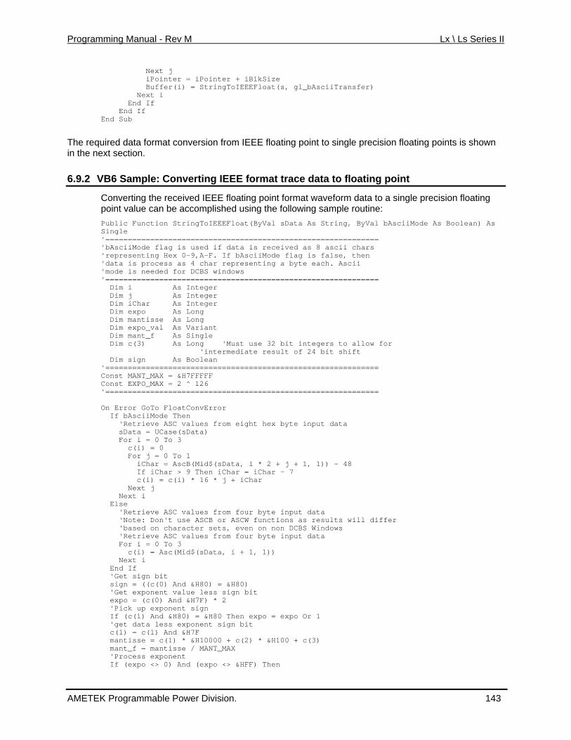
Programming Manual - Rev M Lx \ Ls Series II
Next j iPointer = iPointer Buffer(i) = StringTo
+ iBlkSize iiTransfer)
The required data format conversion from IEEE floating point to single precision floating points is shown in the ne
6.9.2 VB6 Sample: Converting IEEE format trace data to floating point
IEEEFloat(s, gl_bAsc Next i End If End If End Sub
xt section.
Converting the received IEEE floating point format waveform data to a single precision floating
bAsciiMode As Boolean) As
================== d as 8 ascii chars
F. If bAsciiMode flag is false, then as 4 char representing a byte each. Ascii
d for DCBS windows
Dim iChar As Integer
Long 'Must use 32 bit integers to allow for
Dim s'=============================================================
================== On Error GoTo FloatConvError If bAsciiMode Then 'Retrieve ASC values from eight hex byte input data sData = UCase(sData) For i = 0 To 3 c(i) = 0 For j = 0 To 1 iChar = AscB(Mid$(sData, i * 2 + j + 1, 1)) - 48 If iChar > 9 Then iChar = iChar - 7 c(i) = c(i) * 16 * j + iChar Next j Next i Else 'Retrieve ASC values from four byte input data 'Note: Don't use ASCB or ASCW functions as results will differ 'based on character sets, even on non DCBS Windows 'Retrieve ASC values from four byte input data For i = 0 To 3 c(i) = Asc(Mid$(sData, i + 1, 1)) Next i End If 'Get sign bit sign = ((c(0) And &H80) = &H80) 'Get exponent value less sign bit expo = (c(0) And &H7F) * 2 'Pick up exponent sign If (c(1) And &H80) = &H80 Then expo = expo Or 1 'get data less exponent sign bit c(1) = c(1) And &H7F mantisse = c(1) * &H10000 + c(2) * &H100 + c(3) mant_f = mantisse / MANT_MAX 'Process exponent If (expo <> 0) And (expo <> &HFF) Then
point value can be accomplished using the following sample routine: StringToIEEEFloat(ByVal sData As String, ByVal Public Function
Single '===========================================
if data is receive'bAsciiMode flag is used 0-9,A-'representing Hex
ess'data is proc'mode is neede'============================================================= Dim i As Integer Dim j As Integer
Dim expo As Long Dim mantisse As Long Dim expo_val As Variant Dim mant_f As Single Dim c(3) As 'intermediate result of 24 bit shift
ign As Boolean
Const MANT_MAX = &H7FFFFF Const EXPO_MAX = 2 ^ 126 '===========================================
AMETEK Programmable Power Division. 143
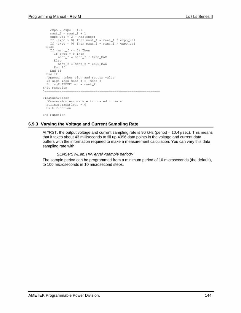
Programming Manual - Rev M Lx \ Ls Series II
expo = expo - 127
MAX
End If 'Append number sign and return value If sign Then mant_f = -mant_f StringToIEEEFloat = mant_f Exit Function '============================================================= FloatConvError: 'Conversion errors are truncated to zero StringToIEEEFloat = 0 Exit Function End Function
6.9.3 Varying the Voltage and Current Sampling Rate
mant_f = mant_f + 1 expo_val = 2 ^ Abs(expo) If (expo > 0) Then mant_f = mant_f * expo_val If (expo < 0) Then mant_f = mant_f / expo_val Else If (mant_f <> 0) Then If expo = 0 Then mant_f = mant_f / EXPO_MAX Else mant_f = mant_f * EXPO_ End If End If
At *RST, the output voltage and current sampling rate is 96 kHz (period = 10.4 µsec). This means that it takes about 43 milliseconds to fill up 4096 data points in the voltage and current data buffers with the information required to make a measurement calculation. You can vary this data sampling rate with:
SENSe:SWEep:TINTerval <sample period> The sample period can be programmed from a minimum period of 10 microseconds (the default), to 100 microseconds in 10 microsecond steps.
AMETEK Programmable Power Division. 144
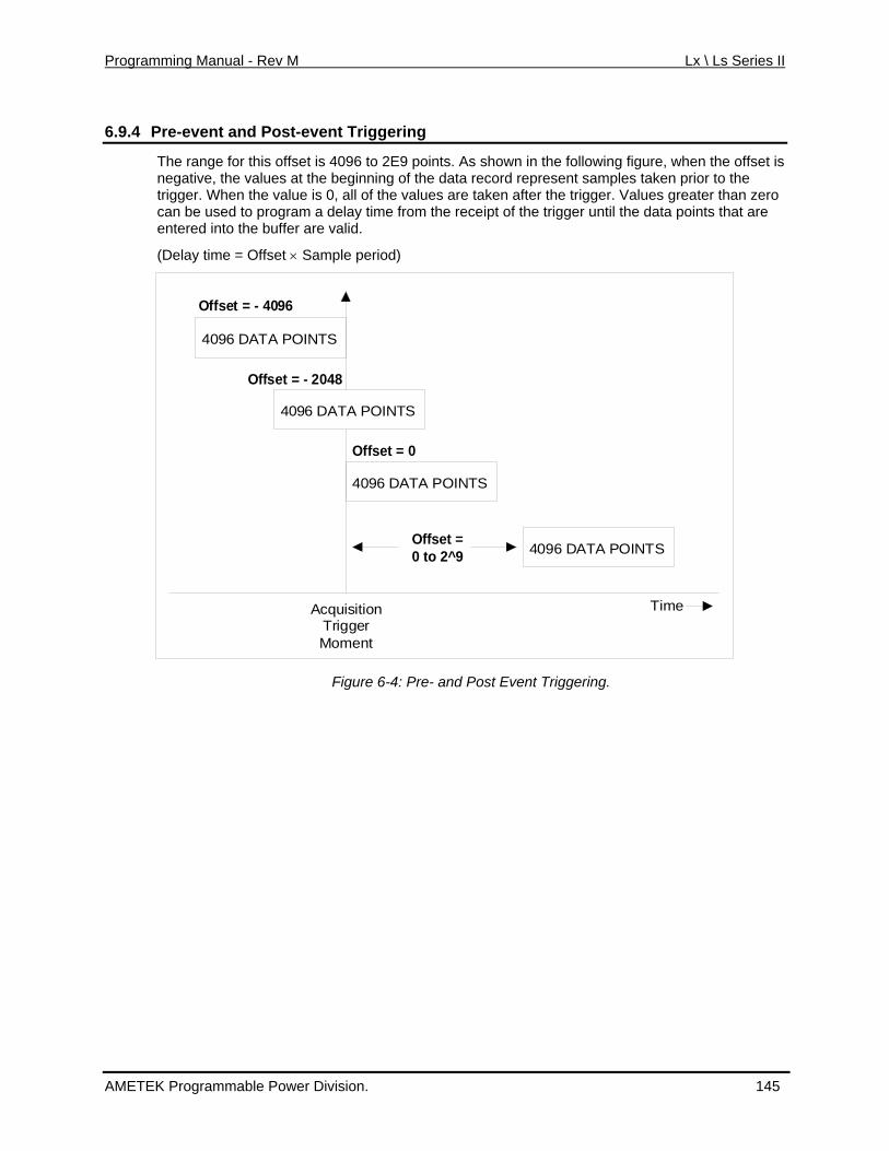
Programming Manual - Rev M Lx \ Ls Series II
6.9.4 re-event and Post-event Triggering P
The range for this offset is 4096 to 2E9 points. As shown in the following figure, when the offset isnegative, the values at the beginning of the data record represent samples taken prior to thetrigger. When the value is 0, all of the values are taken after the trigger. Values greater than zerocan be used to program a delay time from the receipt of the trigger until the data points that areentered into the buffer are valid.
(Delay time = Offset × Sample per
iod)
4096 DATA POINTS
4096 DATA POINTS
4096 DATA POINTS
TimeAcquisitionTrigger
Offset = - 4096
Offset = - 2048
Moment
Offset = 0 to 2^9
Offset = 0
4096 DATA POINTS
Figure 6-4: Pre- and Post Event Triggering.
AMETEK Programmable Power Division. 145
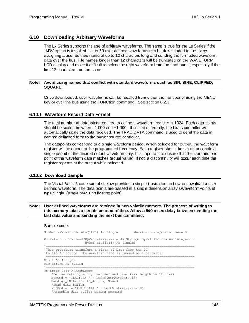
Programming Manual - Rev M Lx \ Ls Series II
6.10 Downloading Arbitrary Waveforms
The e is true for the Ls Series if the -ADV option is installed. Up to 50 user defined waveforms can be downloaded to the Lx by
runcated on the WAVEFORM the front panel, especially if the
Note:
Lx Series supports the use of arbitrary waveforms. The sam
assigning a user defined name of up to 12 characters long and sending the formatted waveform data over the bus. File names longer than 12 characters will be t
ay and make it difficult to select the right waveform fromLCD displfirst 12 characters are the same.
Avoid using names that conflict with standard waveforms such as SIN, SINE, CLIPPED, SQUARE.
Once downloaded, user waveforms can be recalled from either the front panel using the MENUkey or over the bus using the FUNCtion command. See section 6.2.1.
6.10.1 Waveform Record Data Format
The total number of datapoints required to define a waveform register is 1024. Each data points should be scaled between –1.000 and +1.000. If scaled differently, the Lx/Ls controller will automatically scale the data received. The TRAC:DATA command is used to send the data in
T ts corres aveform hen selected for output, the waveform register will be output at the programmed frequency.s riod of the de t waveform on d point of the waveform data matches (equal valu he register repeats at the ile selected.
6.10.2 D Sample
comma delimited form to the power source controller.
he datapoin pond to a single w period. W Each register should be set up to conain a
ly. It is important to ensure that the start and ene). If not, a discontinuity will occur each time t
ingle pe sired outpu
output wh
ownload
The Visual Basic 6 code sample below provides defined waveform. The data points are passed i type Single. (single precision floating point).
Note: User defined waveforms are retained in non- to
a simple illustration on how to download a usern a single dimension array sWaveformPoints of
volatile memory. The process of writingt takes a f time. the last data value and sending the next bus comhis memory certain amount o Allow a 500 msec delay between sending
mand.
Sample code: G nt s Single Private Sub Download(ByVal strWaveName As St ByRef sBuffer() As Sing'============================================================================ ' rocedure trans block of Data fr'to the AC Source. The waveform name is passed as a parameter '============================================================================ Dim i As Integer Dim strCmd As String '===========================================On Error GoTo XFRArbError
catalog e defined name = "TRAC:DE t$(strWaveName
Send gl_iNIBrdId, AC_Adr, s, NLend ‘Send data buffer strCmd = = "TRAC:DATA‘Assemble data buffer string command
lobal sWaveformPoi s(1023) A 'Waveform datapoints, base 0
ring, ByVal iPoints As Integer, _ le)
This p fers a om the PC
=================================
‘Define strCmd
ntry user F " + Lef
(max length is 12 char) ,12)
" + Left$(strWaveName,12)
AMETEK Programmable Power Division. 146
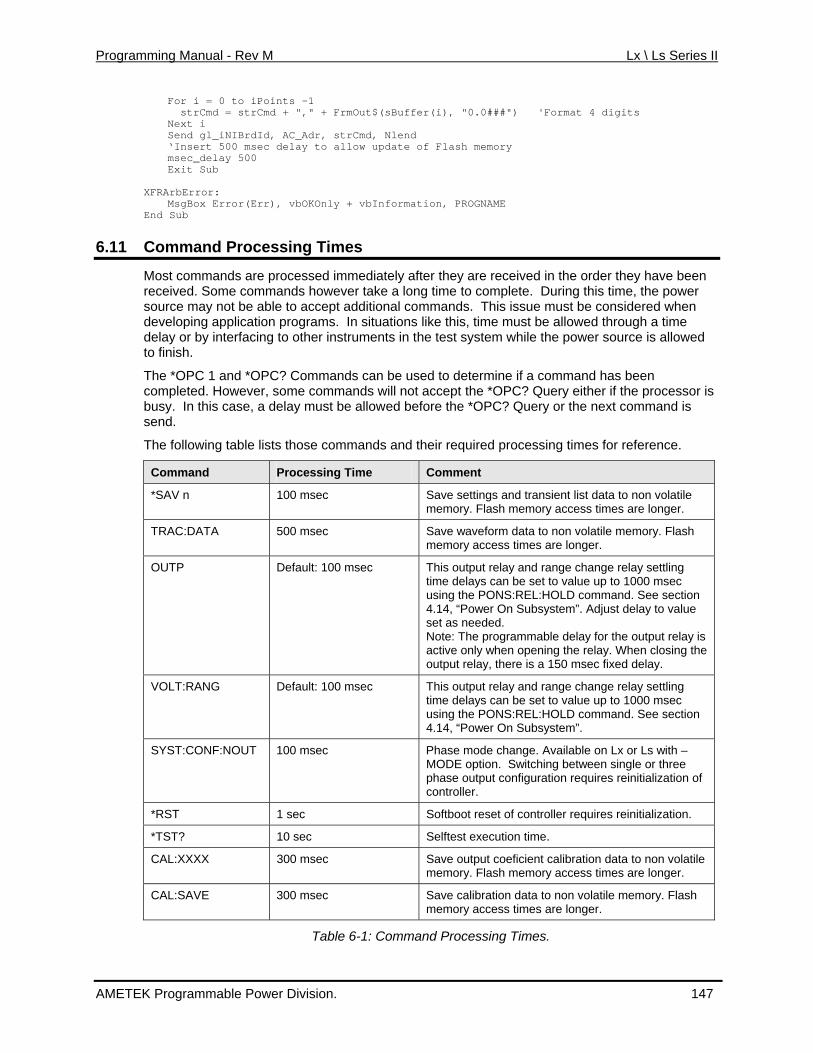
Programming Manual - Rev M Lx \ Ls Series II
For i = 0 to iPoints –1 'Format 4 digits
mation, PROGNAME
6.11
strCmd = strCmd + "," + FrmOut$(sBuffer(i), "0.0###") Next i Send gl_iNIBrdId, AC_Adr, strCmd, Nlend ‘Insert 500 msec delay to allow update of Flash memory msec_delay 500 Exit Sub
XFRArbError: MsgBox Error(Err), vbOKOnly + vbInfor
End Sub
Command Processing Times
Most commands are processed immediately after they are received in the order they have beenreceived. Some commands however take a long time to complete. During this time, the power
source may not be able to accept additional commands. This issue must be considered when . In situations like this, time must be allowed through a time struments in the test system while the power source is allowed
*OPC? Commands can be used to determine if a command has been completed. However, some commands will not accept the *OPC? Query either if the processor is
be allowed before the *OPC? Query or the next command is
developing application programsdelay or by interfacing to other into finish.
The *OPC 1 and
busy. In this case, a delay mustsend.
The following table lists those commands and their required processing times for reference.
Command Processing Time Comment
*SAV n 100 msec tings and transient list data to non volatile longer.
Save setmemory. Flash memory access times are
TRAC:DATA 500 msec ory. Flash ory access times are longer.
Save waveform data to non volatile memmem
OUTP Default: 100 msec settling 00 msec See section
, “Power On Subsystem”. Adjust delay to value
put relay is en closing the elay.
This output relay and range change relaytime delays can be set to value up to 10using the PONS:REL:HOLD command. 4.14set as needed. Note: The programmable delay for the outactive only when opening the relay. Whoutput relay, there is a 150 msec fixed d
VOLT:RANG Default: 100 msec This output relay and range change relay settling time delays can be set to value up to 1000using the PONS:REL:HOLD command. See 4.14, “Power On Subsystem”.
msec section
SYST:CONF:N –or three
nfiguration requires reinitialization of controller.
OUT 100 msec Phase mode change. Available on Lx or Ls withMODE option. Switching between single phase output co
*RST 1 sec ller requires reinitialization. Softboot reset of contro
*TST? 10 sec Selftest execution time.
CAL:XXXX 300 msec Save output coeficient calibration data to non volatile memory. Flash memory access times are longer.
CAL:SAVE 300 msec Save calibration data to non volatile memory. Flash memory access times are longer.
Table 6-1: Command Processing Times.
AMETEK Programmable Power Division. 147
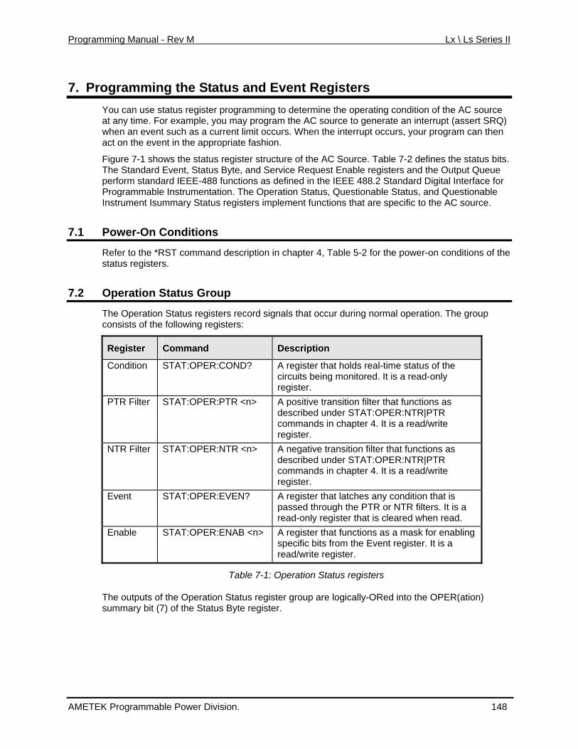
Programming Manual - Rev M Lx \ Ls Series II
7. Programming the Status and Event Registers You can use status register programming to determine the operating condition of the AC source at any time. For example, you may program the AC source to generate an interrupt (assert SRQ) when an event such as a current limit occurs. When the interrupt occurs, your program can then act on the event in the appropriate fashion.
Figure 7-1 shows the status register structure of the AC Source. Table 7-2 defines the status bits. The Standard Event, Status Byte, and Service Request Enable registers and the Output Queue perform standard IEEE-488 functions as defined in the IEEE 488.2 Standard Digital Interface for Programmable Instrumentation. The Operation Status, Questionable Status, and Questionable Instrument Isummary Status registers implement functions that are specific to the AC source.
7.1 Power-On Conditions
Refer to the *RST command description in chapter 4, Table 5-2 for the power-on conditions of the status registers.
7.2 Operation Status Group
The Operation Status registers record signals that occur during normal operation. The group consists of the following registers:
Register Command Description
Condition STAT:OPER:COND? A register that holds real-time status of the circuits being monitored. It is a read-only register.
PTR Filter STAT:OPER:PTR <n> A positive transition filter that functions as described under STAT:OPER:NTR|PTR commands in chapter 4. It is a read/write register.
NTR Filter STAT:OPER:NTR <n> A negative transition filter that functions as described under STAT:OPER:NTR|PTR commands in chapter 4. It is a read/write register.
Event STAT:OPER:EVEN? A register that latches any condition that is passed through the PTR or NTR filters. It is a read-only register that is cleared when read.
Enable STAT:OPER:ENAB <n> A register that functions as a mask for enabling specific bits from the Event register. It is a read/write register.
Table 7-1: Operation Status registers
The outputs of the Operation Status register group are logically-ORed into the OPER(ation) summary bit (7) of the Status Byte register.
AMETEK Programmable Power Division. 148
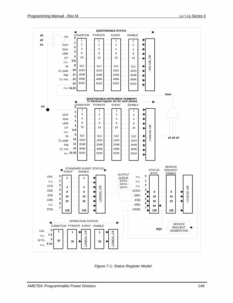
Programming Manual - Rev M Lx \ Ls Series II
1248
16
5121024204840968192
124816
5121024204840968192
1248
16
5121024204840968192
1248
16
5121024204840968192
QUESTIONABLE STATUSCONDITION PTR/NTR EVENTOV
P
OTn.u.
RIeakRail
s
.
ENABLE
OCSOAUNR
CL p
CL rm
n.u
1248
16
5121024204840968192
124816
5121024204840968192
1248
16
204840968192
5121024
1248
16
5121024204840968192
QUESTIONABLE INSTRUMENT ISUMMARY
CONDITION PTR/NTR EVENT ENABLE(1 identical register set for each phase)
OCPSOA
RTu.RIk
ails
u.
UNOn.
CL peaR
CL rmn.
0
123
45-8
9
10111213
14,15
0
123
45-8
9
101112
13-15
Isum
ø3ø2ø1
OV
ø1 ø2 ø3
STATUSBYTE
SERVICEREQUESTENABLE
n.u.
n.u.
n.u.
QUES
MAV
ESB
OPER
012
34
5
81632
128
EVENT ENABLE
OP
n.
C
u.
E
DE
E
E
n.u.
PON
6
7
1
48
32
128
OY
D
EX
CM
012
34
516
1
48
1632
128
STANDARD EVENT STATUS
MSS 6
764
81632
128
SERVICEREQUEST
GENERATION
DATADATADATA
OUTPUTQUEUE
RQSCAL
n.u.
WTG
n.u.
01-4
56-15
1
32
OPERATION STATUS
1
32
1
32
CONDITION PTR/NTR EVENT ENABLE
Figure 7-1: Status Register Model.
AMETEK Programmable Power Division. 149
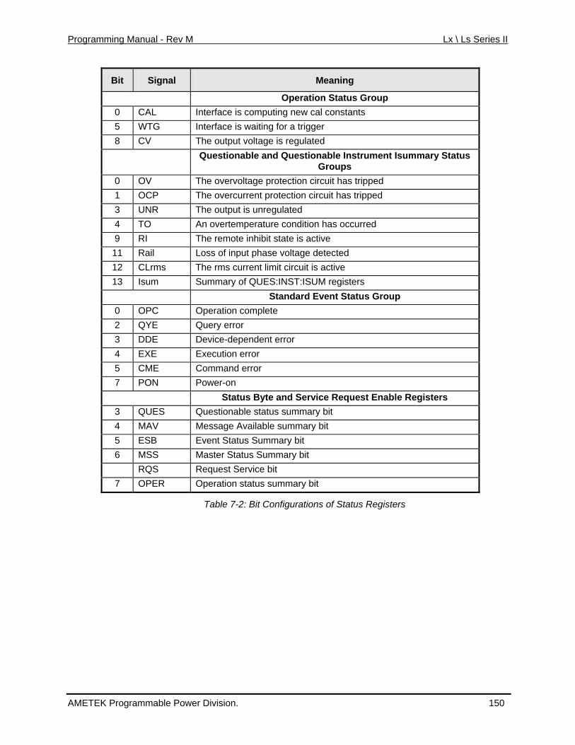
Programming Manual - Rev M Lx \ Ls Series II
Bit Signal Meaning
Operation Status Group 0 CAL Interface is computing new cal constants 5 WTG Interface is waiting for a trigger 8 CV The output voltage is regulated Questionable and Questionable In mmary Status strument Isu
Groups 0 OV The overvoltage protection circuit has tripped 1 OCP The overcurrent protection circuit has tripped 3 UNR The output is unregulated 4 TO An overtemperature condition has occurred 9 RI The remote inhibit state is active 11 Rail aseLoss of input ph voltage detected 12 CLrms The rms current limit circuit is active 13 Isum Summary of QUES:INST:ISUM registers
Standard Event Status Group 0 OPC Operation complete 2 QYE Query error 3 DDE t Device-dependen error 4 EXE Execution error 5 CME Command error 7 PON Power-on Status Byte and Service Request Enable Registers
3 QUES Questionable status summary bit 4 MAV Message Available summary bit 5 ESB Event Status Summary bit 6 MSS Master Status Summary bit RQS Request Service bit
7 OPER Operation status summary bit
Table 7-2: Bit Configurations of Status Registers
AMETEK Programmable Power Division. 150
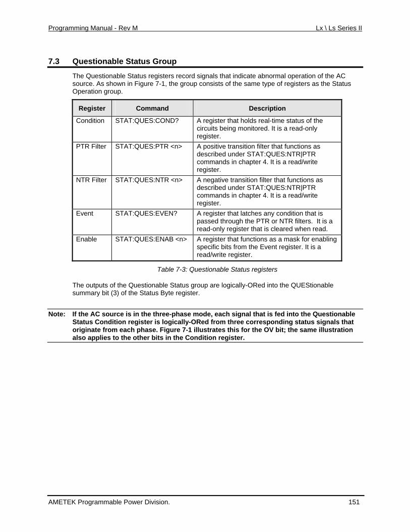
Programming Manual - Rev M Lx \ Ls Series II
7.3 Questionable Status Group
The Questionable Status registers record signals that indicate abnormal operation of the ACsource. As shown in Figure 7-1, the group consists of the same type of registers as the Status Operation group.
Register Command Description
Condit D? A register that holds real-time status of the red. It is a read-only
ion STAT:QUES:CONcircuits being monitoregister.
PTR F > A positive transition filter that functions as
commands in chapter 4. It is a read/write register.
ilter STAT:QUES:PTR <ndescribed under STAT:QUES:NTR|PTR
NTR Filter STAT:QUES:NTR <n> A negative transition filter that functions as described under STAT:QUES:NTR|PTR commands in chapter 4. It is a read/write register.
Event EN?
STAT:QUES:EV A register that latches any condition that is passed through the PTR or NTR filters. It is aread-only register that is cleared when read.
Enable AB <STAT:QUES:EN n> A register that functions as a mask for enabling specific bits from the Event register. It is a read/write register.
Table 7
The outputs o Stasummary bit (3) of the Status Byte re
Note: If the AC source is in the three-phase mode, each signal that is fed into the Questionable
-3: Questionable Status registers
f the Questionable tus group are logically-ORed into the QUEStionable gister.
Status Condition register is logically-ORed from three corresponding status signals that originate from each phase. Figure 7-1 illustrates this for the OV bit; the same illustration also applies to the other bits in the Condition register.
AMETEK Programmable Power Division. 151
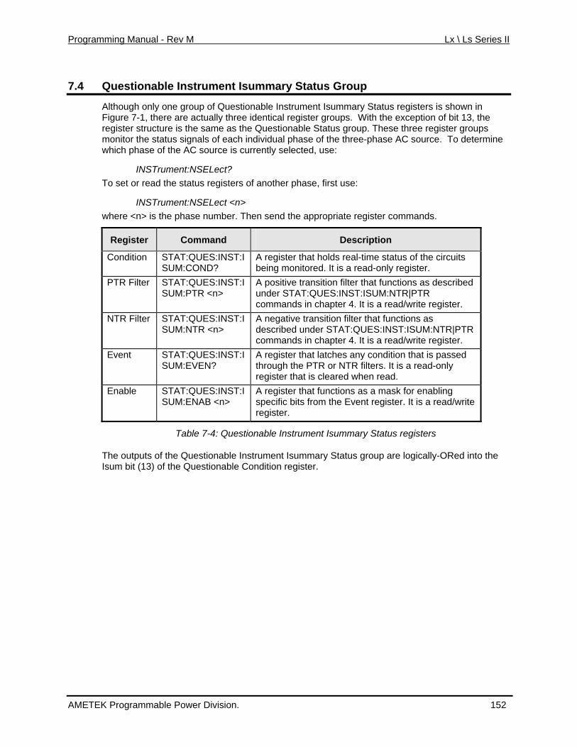
Programming Manual - Rev M Lx \ Ls Series II
7.4 Questionable Instrument Isummary Status Group
Although only one group of Questionable Instrument Isummary Status registers is shown Figure 7-1, there are actually three identical register groups. With the exception of bit 1register structure is the same as the Questionable Status group. These three register group
in 3, the
s
r commands.
monitor the status signals of each individual phase of the three-phase AC source. To determinewhich phase of the AC source is currently selected, use:
INSTrument:NSELect? To set or read the status registers of another phase, first use:
INSTrument:NSELect <n> where <n> is the phase number. Then send the appropriate registe
Register Command Description
Condition STAT:QUES:INST:ISUM:COND?
A register that holds real-time status of the circuits being monitored. It is a read-only register.
PTR Filter STAT:QUES:INST:ISUM:PTR <n>
A positive transition filter that functions as described under STAT:QUES:INST:ISUM:NTR|PTR commands in chapter 4. It is a read/write register.
NTR Filter STAT:QUES:INST:INTR <n>
A negative transition filter that functions as described under STAT:QUES:INST:ISUM:NTR|PTR commands in chapter 4. It is a read/write register.
SUM:
Event STAT:QUES:INST:I:EVEN?
A register that latches any condition that is passed through the PTR or NTR filters. It is a read-only register that is cleared when read.
SUM
Enable STAT:QUES:INST:ISUM:ENAB <n>
A register that functions as a mask for enabling specific bits from the Event register. It is a read/write register.
Table 7-4: Questionable Instrument Isummary Status registers
The outputs of the Questionable Instrument Isummary Status group are logically-ORed into the Isum bit (13) of the Questionable Condition register.
AMETEK Programmable Power Division. 152
Programming Manual - Rev M Lx \ Ls Series II
7.5 Standard Event Status Group
This group consists of an Event register and an Enable register that are programmed by Common commands. The Standard Event register latches events relating to interface communication status (see Figure 7-1). It is a read-only register that is cleared when read.
ter functions similarly to the enable registers of the Operation The Standard Event Enable regisand Questionable status groups.
Command Action
*ESE programs specific bits in the Standard Event Enable register.
the Standard Event register is set whenever the AC source is turned on. The most r PON is to generate an SRQ at power-on following an unexpected loss of power.
*PSC ON clears the Standard Event Enable register at power-on.
*ESR? reads and clears the Standard Event register.
The PON (Power On) Bit
The PON bit incommon use foTo do this, bit 7 of the Standard Event Enable register must be set so that a power-on event registers in the ESB (Standard Event Summary Bit). Bit 5 of the Service Request Enable register must be set to permit an SRQ to be generated, and *PSC OFF must be sent. The commands to accomplish these conditions are:
*PSC OFF
*ESE 128
*SRE 32
AMETEK Programmable Power Division. 153
Programming Manual - Rev M Lx \ Ls Series II
7.6 Status Byte Register
This register summarizes the information from all other status groups as defined in the IEEE strumentation. The bit configuration is
shown in Table 5-3. 488.2 Standard Digital Interface for Programmable In
Command Action
serial p ads and clears the data in the register (returns RQS in bit 6)
Service Request Enable register. MSS is set whenever the AC source has one or more reasons for requesting service. *STB? reads the MSS in bit position 6 of the response but does not clear any of the bits in the Status Byte register.
The RQ
The RQS bit is a latched version of the MSS bit. Whenever the AC source requests service, it
onse. The remaining bits of the Status Byte register are not disturbed.
The er mes ts the
*STB? reads the data in the register but does not clear it (returns MSS in bit 6)
oll re
The MSS Bit
This is a real-time (unlatched) summary of all Status Byte register bits that are enabled by the
S Bit
sets the SRQ interrupt line true and latches RQS into bit 6 of the Status Byte register. When the controller does a serial poll, RQS is cleared inside the register and returned in bit position 6 of theresp
The MAV bit and Output Queue
Output Queue is a first-in, first-out (FIFO) data register that stores AC source-to-controllsages until the controller reads them. Whenever the queue holds one or more bytes, it seMAV bit (bit 4) of the Status byte register.
AMETEK Programmable Power Division. 154
Programming Manual - Rev M Lx \ Ls Series II
7.7 Examples
7.7.1 Determining the Cause of a Service Interrupt
You can determine the reason for an SRQ by the following actions:
1. Det
each summary bit to determine which events caused the summary bit to be set. Use:
Note:
ermine which summary bits are active. Use
*STB? or serial poll
2. Read the corresponding Event register for
STATus:QUEStionable:EVENt?
STATus:OPERation:EVENt?
ESR?
When an Event register is read, it is cleared. This also clears the corresponding summary bit.
3. Remove the specific condition that caused the event. If this is not possible, the event may be disabled by programming the corresponding bit of the status group Enable register or NTR terrupt is to disable the service request by programming the appropriate bit of the Service Request Enable register.
7.7.2 Servicin
|PTR filter. A faster way to prevent the in
g Questionable Status Events
This example assumes you want a service request generated whenever the AC source's
rogram the Questionable Status PTR register to allow a positive transition at bits 0, 1, or 4 to be latched into the Status Event register. Use:
(1 + 2 + 16 = 19) he latched events to be summed
3. rogram the Service Request Enable register to allow the QUES summary bit from the
*SRE 8 4. tionable
overvoltage, overcurrent, or overtemperature circuits have tripped. From Figure 7-1, note the required path for Questionable Status conditions at bits 0, 1, and 4 to generate a service request (RQS) at the Status Byte register. The required register programming is as follows:
1. P
STATus:QUEStionable:PTR 19 2. Program the Questionable Status Enable register to allow t
into the QUES summary bit. Use:
STATus:QUEStionable:ENABle 19 PStatus Byte register to generate RQS. Use:
When you service the request, read the event register to determine which QuesStatus Event register bits are set and clear the register for the next event. Use:
STATus:QUEStionable:EVENt?
AMETEK Programmable Power Division. 155
Programming Manual - Rev M Lx \ Ls Series II
7.7.3 Monitoring Both Phases of a Status Transition
You can monitor a status signal for both its positive and negative transitions. For example, to generate RQS when the AC t limit) condition or leaves that condition, program the Questionable Status PTR/NTR filter as follows:
STATus:QUEStionable:PTR 4096;NTR 4096
STATus:QUEStionable:ENABle 4096;*SRE 8 The PTR filter will cause the QUES summary bit to set RQS when CLrms occurs. When the controller subsequently reads the event register with STATus:QUEStionable:EVEN?, the register is cleared. When CLrms subsequently goes false, the NTR filter causes the QUES summary bit to again set RQS.
7.7.4 Programming the Trigger In and Trigger Out SMA connectors
source either enters the CLrms (rms curren
The AC source has two SMA connectors labeled Trigger In1and Trigger Out2(see Figure 7-2). Refer to specifications in the User's Manual for the electrical parameters.
Trigger In1 SMA
This chassis-referenced digital input can be selected as a source for transient or measurement triggers. This allows an action to be synchronized to an external signal. The trigger is recognized on a high-to-low transition of the input signal. The minimum pulse width of the signal is 1 microsecond. To select the Trigger In connector as the trigger source, use:
TRIGger:SEQuence1:SOURce EXTernal or TRIGger:TRANsient:SOURce EXTernal
TRIGger:SEQuence3:SOURce EXTernal or TRIGger:ACQuire:SOURce EXTernal
Trigger Out1 SMA
This chassis-referenced digital output can be programmed to supply a pulse output at the leading or trailing edge of a step or pulse, or at the leading edge of any point in a list sequence. The output signal is nominally a 10 microsecond low-true pulse. To enable the Trigger Out connector, use:
OUTPut:TTLTrg:STATe ON At *RST, the Trigger Out connector is off.
To select a trigger source for the Trigger Out connector, use:
OUTPut:TTLTrg:SOURce BOT | EOT | LIST
BOT - specifies that the pulse is output at the beginning of a transient. This is the *RST setting.
EOT - specifies that the pulse is output at the end of a transient.
LIST - specifies that the pulse position is defined by the LIST:TTLTrg command.
You can also specify the Trigger Out connector as a trigger source for measurement trigger sequences. Use:
TRIGger:SEQuence3:SOURce TTLT or TRIGger:ACQuire:SOURce TTLT
AMETEK Programmable Power Division. 156
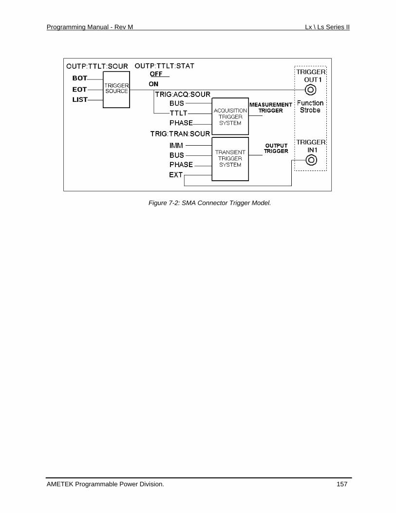
Programming Manual - Rev M Lx \ Ls Series II
Figure 7-2: SMA Connector Trigger Model.
AMETEK Programmable Power Division. 157
Programming Manual - Rev M Lx \ Ls Series II
7.8 Remote Inhibit and Discrete Fault Indicator
The remote inhibit and discrete fault indicators are implemented through the respective IFLT connections on the rear panel. Refer to the User's Manual for the electrical parame
NH and ters.
7.8.1 Remote Inhibit (RI)
Remote inhibit is an external, chassis-referenced logic signal routed through the rear panel INH connection, which allows an external device to signal a fault.
To select an operating modes for the remote inhibit signal, use:
TPut:RI:MOD
LATChing
LIVE t to disable the output in a non-latching manner. When no effect
OFF
7.8.2 Discrete Fault Indicator (DFI)
OU E LATChing | LIVE | OFF
causes a low-true signal on the INH input to disable the output. The only way to clear the latch is by sending an OUTPut:PROTection:CLEAR command while the INH input is false.
allows the RI inpuINH is low true, the output is disabled. When INH is high, it hason the output.
disables the INH input.
The discrete fault indicator is a chassis-referenced, open-collector logic signal connected to the rear panel FLT connection, that can be used to signal external devices when a fault condition is detected. To select the internal fault source that drives this signal, use:
OUTPut:DFI:SOURce QUEStionable | OPERation | ESB | RQS | OFF
QUEStionable selects the Questionable event summary bit (bit 3 of the Status Byte Register)
OPERation selects the Operation Event summary bit (bit 7 of the Status Byte Register)
ESB selects the Standard Event summary bit (bit 5 of the Status Byte Register)
RQS selects the Request Service bit (bit 6 of the Status Byte Register)
OFF selects no DFI source
To enable or disable the DFI output, use:
OUTPut:DFI:STATe ON | OFF
AMETEK Programmable Power Division. 158
Programming Manual - Rev M Lx \ Ls Series II
7.9 SCPI Command Completion
SCPI commands sent to the AC source are processed either sequentially or in parallel. s finish execution before a subsequent command begins. Parallel er commands to begin executing while the parallel command is still
.
ding operations are completed.
es a 1 in the Output Queue when all pending operations have d. Because it requires your program to read the returned value
uting the next program statement, *OPC? can be used to
Sequential commandcommands allow othexecuting. Commands that affect list and trigger actions are among the parallel commands
The *WAI, *OPC, and *OPC? common commands provide different ways of indicating when all transmitted commands, including any parallel ones, have completed their operations. The syntaxand parameters for these commands are described in chapter 4. Some practical considerations for using these commands are as follows:
*WAI This prevents the AC source from processing subsequent commandsuntil all pen
*OPC? This placcompletebefore execcause the controller to wait for commands to complete before proceeding with its program.
*OPC This sets the OPC status bit when all pending operations have completed. Since your program can read this status bit on an interrupt basis, *OPC allows subsequent commands to be executed.
AMETEK Programmable Power Division. 159
Programming Manual - Rev M Lx \ Ls Series II
8. Option Commands
8.1 Introduction
The Lx and Ls Series offer a number of options that are implemented in the power source controller. If one or more of these options are installed, they may be used from both the fronpanel and the interface. For front panel operation of any of these firmware options, consult the User Manual supplied with the unit. For use in an automated test system, this chapter contains the command sub system syntax for the available test options.
Specifically, the following firmware options are available at the time of this manual’s printing:
t
–704
•
• Abb
The n que d may be added over time. Consult the factory for additional information on firmware options not listed here but prese
• RTCA/DO-160D, Option –1605
• MIL-STD 704, Option 6
MIL-STD 704F, Option –704F7
reviated Plain English, Option –APE8. (Bundled with -GPIB option)
AC power source will report all installed options, including any firmware options, wherie using the SYST:CONF:BYTE? or *OPT? command. Additional firmware options
nt on your unit.
5 Option -160 requires Lx/Ls firmware version 0.88 or higher. 6 Option -704 requires Lx/Ls firmware version 0.98 or higher. 7 Option –704F requires Lx/Ls f8 Option APE requires Lx/Ls firmware version 0.98 or higher. Check CI website for firmware updates.
irmware version 1.00 or higher.
AMETEK Programmable Power Division. 160
Programming Manual - Rev M Lx \ Ls Series II
8.2 APE Command Language (Abbreviated Plain English)
The APE (Abbreviated Plain English) command language syntax is available as an option on the Ls Series only. This option is not offered on Lx Series models. The APE language provides backward compatibility with California Instruments’ L Series legacy products.
This option is bundled with the GPIB interface option on the Ls Series. If present, Ls Series units
The presence of this option can be determined by using ST:CONF? command queries. Note that the Ls can always be operated in SCPI . If the –APE option is installed, it can be switched to APE mode. In APE mode,
the E
This se ill availablprocedu
• ATION screen, select the LANG field. This field can be toggled between
•
of similar power and voltage rating can be used to replace L Series in test systems running programs written using the APE syntax.the *OPT? or SYmode as needed
IEE 488.2 common commands such as *IDN? are still available but not SCPI commands.
ction of the manual covers the APE syntax. Note that the SCPI command language is ste as well. The Ls can be configured to power up in either mode of operation. The re is as follows:
From the front panel, select the CONFIGURATION screen using the MENU key. In the CONFIGURSPCI or APE using the shuttle knob.
From the bus, send the following commands depending on the present mode of operation.
Present Mode To change to other language mode, send:
APE mode SCPI
SCPI mode SYST:LANG APEN
Table 8-1: APE to SCPI mode change commands
8.2.1 Introduction
Remoteaddressnumerical value or other argument. The description of the abbreviations for GPIB messages use device d(ex. FR
programming through the IEEE-488 Interface (GPIB) consists of sending the unit and the proper ASCII alphanumeric characters to identify the parameter and the
d in this section is listed in Table 3-10. These abbreviations must not be confused with the ependent abbreviations used to describe the AC Power System operating parameters
Q=Frequency, etc.).
AMETEK Programmable Power Division. 161
Programming Manual - Rev M Lx \ Ls Series II
8.2.2 L Series Backward Compatibility Issues
Although every effort has been made to mimic the L Series bus operation as closely as possible, the endcompared to the L Series. This inevitably leads to subtle differences of execution of the same application programs on each unit.
Specific may require slight modifications of programs that may be affected by them.
Discrepancies:
lt in the transient being aborted and the output voltage set to
ommand followed by an AMP100
V over a 10 second period using a 10V/s slew
ld the last error message in its error buffer until the TLK STA query eceived. Once the TLK STA has been received, the error buffer is cleared.
angeve the
This may require the require o be set when using an Ls before g power to a EUT. On the L mporary loss of output was not required.
e California Instruments L S mand to the ause the front is due to
ller.
nstruments L S and to the Ls Controller will not cause the GPIB listen address to be changed immediately. Instead, a powe not recommended to change the GPIB listen address as part of any application program on the Ls Series.
CRL STP and PHZ STP No support for current and phase angle ramps CAL AMP STP No support for calibration ramp CAL PWR There is no power calibration requirement on the Ls. TLK MNU Menus are different on Ls Series CLMB and CLMC Query format (TLK) only.
8. The following APE commands must be at the end of a compound command string or used as the only command in a message string: SNC, WVF, CLK. If followed by any other APE command in the same message string, a syntax error will be generated.
9. The MOD command cannot be used with other APE commands in the same message string.
-user should be aware that the Ls uses a completely different controller and operating system
ally, the following discrepancies should be noted and
1. APE Programming commands received during the execution of a transient will stop the transient as was the case on the L Series but any program values associated with the command will not be accepted. Thus, while sending AMP100 to an L Series during transient execution will resu100 V, the Ls will only abort the transient program. If it is required to set the voltage, theAMP100 command should be replaced with an AMP ccommand.
2. Ramp transients will be slewed in a linear fashion rather than in discrete steps as defined by the STEP value. Thus, the Ls determines the required slew rate. For example, where an L Series will step the voltage every second by 10 Volt to go to 100 V in 10 seconds, the Ls will ramp gradually from 0 to 100 rate.
3. The Ls will hormessage is
4. A ch e of the waveform THD level will cause the output to go to zero momentarily. How r a change from zero THD to the previously set THD level will not affect output. applyin
d THD level tSeries, this te
5. Unlike th eries controllers, sending a TLK XXX comLs Controller will not c panel to display the measurement screen. Thisthe different measurement screen layout and organithe L series contro
zation of the Ls series controller versus
6. Unlike the California I eries controllers, sending a CFGA XXX comm
r cycle is required for the new GPIB listen address to take effect. Thus, it is
7. The following APE commands are not supported due to hardware incompatibilities of theLs Controller with the L series controllers:
AMETEK Programmable Power Division. 162
Programming Manual - Rev M Lx \ Ls Series II
Configuration Issues:
iguration related issues are unique to the Ls Series when operated in APE
language to SCPI when in APE mode.
5. Power source configuration queries should be done in SCPI mode. However the “TLK command will respond with a configuration byte similar to that of the L series
If the Ls Series AC power source is powered up in APE mode, the normal recall power up setting from a user-assigned setup register will NOT take place. Instead a power on initialization similar to that of the L Series is used as shown below.
The factory default values for APE power on settings are:
ALMA 0 FLMA 60 Hz INIA 0 V INIC n A where n is the maximum current limit of the system at a given range.
The following confmode and did not apply to the L Series:
1. The Square wave command (WVF SQW) is accepted only if the advance feature option is installed. (Option –ADV)
2. The System configuration language bit must be set to enable the APE option. See *OPT? Command in SCPI syntax section of this manual.
3. SYSTem:LANGuage APENglish will change the language to APE when in SCPI mode.
4. SCPI will change the
CFGA” APEfor backward compatibility.
6. The CFGA command will be accepted but changes to the GPIB listen address will not take effect until input power on the Ls unit is cycled.
Power-on Initialization:
APE Mode SCPI Mode
ALMA 0 or 8 PONSetup:VRANge <voltage range>
FLMA <initial frequency> PONSetup:FREQuency <initial frequency>
INIA <initial voltage> PONSetup:VOLTage <initial voltage>
INIC<initial current limit> PONSetup:CURRent <initial current limit>
Table 8-2: APE versus SCPI equivalent power initialization commands
Note: When upgrading the firmware on an Ls Series unit that has a firmware revision of 0.90 or less, the above parameters must be reset in APE mode.
AMETEK Programmable Power Division. 163
Programming Manual - Rev M Lx \ Ls Series II
8.2.3 GPIB Address
The GPIB address (also referred to as the unit address) of the Lx / Ls Series power source is the same for either language mode. set at the factory to 1 but may be
The Unit Address can range from 0 through 31. The Unit Address is changed by selecting the CONFIGURATION screen and setting a
e. The value set is retained in non-volatile memory.
CFGA query command. The CFGA ke effect until input ew listen address
8.2.4 A
new valu
In APE mode, the GPIB address is returned by the TLKcommand will be accepted but changes to the GPIB listen address will not tapower on the Ls unit is cycled. This is different than the L Series where the ntakes effect immediately.
PE over RS232
Although not available on the L Series power source, the Ls AC power source also has a RS232C
in capabilities such as GPIB trigger and SRQ may serial interface. It is possible to use the APE mode over RS232C but this mode of operation is not formally supported by California Instruments. Certanot function when using the RS232C interface. In general, it is recommended to use the normal SCPI mode when programming the Ls Series over the RS232C interface.
AMETEK Programmable Power Division. 164
Programming Manual - Rev M Lx \ Ls Series II
8.2.5 Message Format
The message sent to the AC Power System must have the following format for each parameter:
HHHDXXX---------------E±NND
Where:
H = Three letter mnemonic for each message header.
D = Optional header extension (A, B or C) to specify output (ref. Table 8-3)
X = Alpha, numeric or # for message header argument.
E = Optional ASCII E for exponent identification
± = Exponent sign
N = Exponent value 0 to ±63
D = Message string delimiter, (CR) (LF) or (LF)
More than one message header with its corresponding argument may be sent in one setup string
8.2.6 Numeric Data Field
with a common delimiter.
Parameter values may be sent as an unsigned value with a decimal point or a decimal point with an exponent. The phase value may be sent as a signed value.
The Decimal Point for numeric data values may be either sent or inferred. The two following ASCII strings will represent 115 volts.
the 256 byte DAM d. The LSD for to 99.99, 999.9 or
with a decimal point and exponent. The
AMP115
AMP115.0
There may be any number of digits following the decimal point, not to exceed buffer, but only the Least Significant Digit (LSD) of resolution will be recognizeamplitude is 0.1 volts. The LSD for frequency is either 0.01, 0.1 or 1 Hz for up5000 Hz respectively.
Any parameter's numeric value may be of a mixed form umeric, with or without leading zeros, up to a value of ±63. The following exponent may be a n
ASCII strings will represent 115 volts:
AMP1.15E2
AMP1.15E+2
AMP1.15E+02
AMP1150E-1
A positive exponent value is represented by either an ASCII "+" or an unsigned value.
AMETEK Programmable Power Division. 165
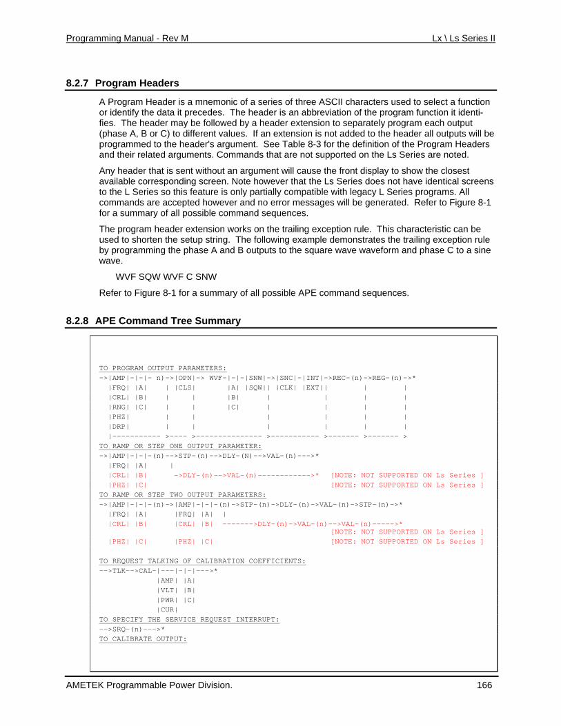
Programming Manual - Rev M Lx \ Ls Series II
8.2.7 Program Headers
A Program Header is a mnemonic of a series of three ASCII characters used to select a function edes. The header is an abbreviation of the program function it identi-followed by a header extension to separately program each output
ded to the header all outputs will be
ommands that are not supported on the Ls Series are noted.
sent without an argument will cause the front display to show the closest ding screen. Note however that the Ls Series does not have identical screens
y L Series programs. All
command sequences.
extension works on the trailing exception rule. This characteristic can be etup string. The following example demonstrates the trailing exception rule
the phase A and B outputs to the square wave waveform and phase C to a sine
VF C SNW
-1 for a summary of all possible APE command sequences.
8.2.8 APE Command Tree Summary
or identify the data it precfies. The header may be (phase A, B or C) to different values. If an extension is not ad
argument. See Table 8-3 for the definition of the Program Headers programmed to the header's and their related arguments. C
Any header that is available corresponto the L Series so this feature is only partially compatible with legac
ever and no error messages will be generated. Refer to Figure 8-1 commands are accepted howossiblefor a summary of all p
The program header the sused to shorten
by programming wave.
WVF SQW W
Refer to Figure 8
TO PROGRAM OUTPUT PARAMETERS: ->|AMP|-|-|- n)->|OPN|-> WVF-|-|-|SNW|->|SNC|-|INT|->REC-(n)->REG-(n)->* |FRQ| |A| | |CLS| |A| |SQW|| |CLK| |EXT|| | | |CRL| |B| | | |B| | | | | |RNG| |C| | | |C| | | | | |PHZ| | | | | | | |DRP| | | | | | | |----------- >---- >--------------- >----------- >------- >------- > TO RAMP OR STEP ONE OUTPUT PARAMETER: ->|AMP|-|-|-(n)-->STP-(n)-->DLY-(N)-->VAL-(n)--->* |FRQ| |A| | |CRL| |B| ->DLY-(n)-->VAL-(n)------------>* [NOTE: NOT SUPPORTED ON Ls Series ] |PHZ| |C| [NOTE: NOT SUPPORTED ON Ls Series ] TO RAMP OR STEP TWO OUTPUT PARAMETERS: ->|AMP|-|-|-(n)->|AMP|-|-|-(n)->
AMETEK Programmable Power Division. 166
STP-(n)->DLY-(n)->VAL-(n)->STP-(n)->* |FRQ| |A| |FRQ| |A| | |CRL| |B| |CRL| |B| ------->DLY-(n)->VAL-(n)-->VAL-(n)----->* [NOTE: NOT SUPPORTED ON Ls Series ] |PHZ| |C| |PHZ| |C| [NOTE: NOT SUPPORTED ON Ls Series ] TO REQUEST TALKING OF CALIBRATION COEFFICIENTS: -->TLK-->CAL-|---|-|-|--->* |AMP| |A| |VLT| |B| |PWR| |C| |CUR| TO SPECIFY THE SERVICE REQUEST INTERRUPT: -->SRQ-(n)--->* TO CALIBRATE OUTPUT:
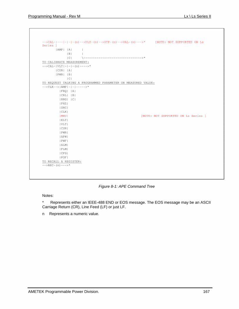
Programming Manual - Rev M Lx \ Ls Series II
-->CAL-|---|-|-|-(n)-->DLY-(n)-->STP-(n)-->VAL-(n)--->* [NOTE: NOT SUPPORTED ON Ls Series ] |AMP| |A| | |B| | -- --------- |C| \-- -------------- ---->* TO CALIBRATE MEASUREMENT: -->CAL-|VLT|-|-|-(n)---->* |CUR| |A| |PWR| |B| |C| TO REQUEST TALKING A PROGRAMMED PARAMETER OR MEASURED VALUE: -->TLK-->|AM --->* P|-|-|-- |FRQ| |A| |CRL| |B| |RNG| |C| |PHZ| |SNC| |CLK| |MNU| Ls Series ] [NOTE: NOT SUPPORTED ON |ELT| |VL T| |CUR| |PWR| |APW| |PWF| |AL M| |FL M| |CFG| |POF| TO RECALL A REGISTER: -->REC-(n)-- * ->
Figure 8-1: APE Co
Notes:
eprese ts either an IE r EOS message. The EOS message may be an ASCII ge Ret n (CR), Line F t LF.
presen s a numeric va
mmand Tree
* R n EE-488 END oCarria ur eed (LF) or jus
n Re t lue.
AMETEK Programmable Power Division. 167
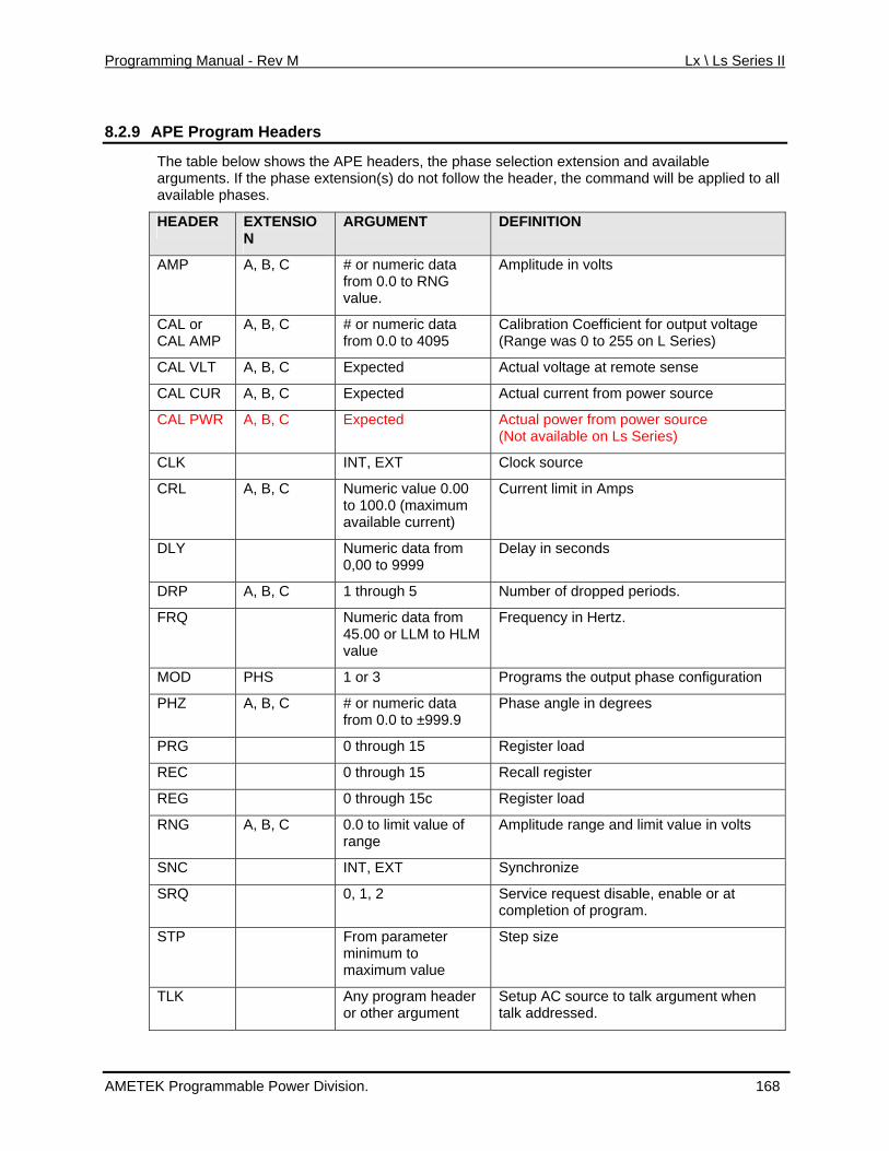
Programming Manual - Rev M Lx \ Ls Series II
8.2.9 APE Program Headers
The table bel shows the A E headers, the phase arguments. If the phase extension(s) do not follow the header, the command will be applied to all
ble pha es.
ow P selection extension and available
availa s
HEADER EXTENSION
ARGUMENT DEFINITION
AMP A, B, C # or numeric data om 0.0 to RNG
volts frvalue.
Amplitude in
CAL or CAL AMP om 0.0 to 4095
A, B, C # or numeric data fr
Calibration Coefficient for output voltage (Range was 0 to 255 on L Series)
CAL VLT A, B, C Expected Actual voltage at remote sense
CAL CUR A, B, C Expected ce Actual current from power sour
CAL PWR xpected A, B, C E Actual power from power source (Not available on Ls Series)
CLK INT, EXT Clock source
CRL A, B, C Numeric value 0.00 100.0 (maximum to
available current)
Current limit in Amps
DLY N0,00 to 9999
umeric data from Delay in seconds
DRP A, B, C 1 through 5 Number of dropped periods.
FRQ Numeric data from 5.00 or LLM to HLM 4
value
Frequency in Hertz.
MOD PHS 1 or 3 Programs the output phase configuration
PHZ A, B, C from 0.0 to ±999.9 # or numeric data Phase angle in degrees
PRG 0 through 15 Register load
REC 0 through 15 Recall register
REG 0 through 15c Register load
RNG A, B, C 0.0 to limit value of range
Amplitude range and limit value in volts
SNC INT, EXT Synchronize
SRQ 0, 1, 2 Service request disable, enable or at completion of program.
STP From parameter minimum to maximum value
Step size
TLK Any program header or other argument
Setup AC source to talk argument when talk addressed.
AMETEK Programmable Power Division. 168
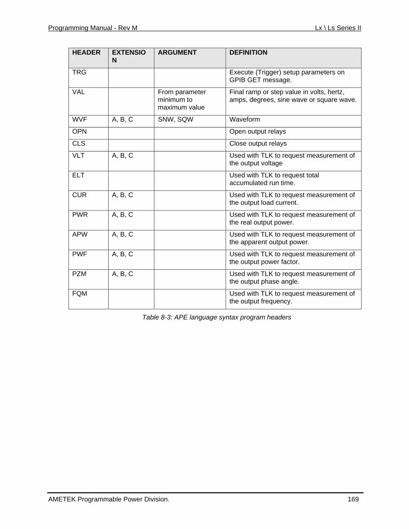
Programming Manual - Rev M Lx \ Ls Series II
HEADER EXTENSION
ARGUMENT DEFINITION
TRG Execute (Trigger) setup parameters onGPIB GET message.
VAL From parameter Final ramp or step value in volts, hertz, . minimum to
maximum value amps, degrees, sine wave or square wave
WVF A, B, C SNW, SQW Waveform
OPN Open output relays
CL Close output relays S
VLT A, B, C Used with TLK to request measurement of the output voltage
ELT Uaccumulated run time.
sed with TLK to request total
CUR A, B, C Used with TLK to request measurement of the output load current.
PWR A, B, C Used with TLK to request measurement of the real output power.
APW A, B, C Used with TLK to request measurement of the apparent output power.
PWF A, B, C Used with TLK to request measurement of the output power factor.
PZM A, B, C Used with TLK to request measurement of the output phase angle.
FQM Used with TLK to request measurement of the output frequency.
Table 8-3: A e syntaPE languag x program headers
AMETEK Programmable Power Division. 169
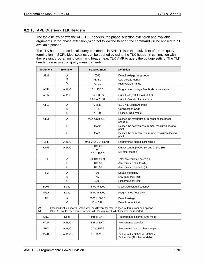
Programming Manual - Rev M Lx \ Ls Series II
8.2.10 APE Queries - TLK Headers
The table below shows the APE TLK headers, the phasarguments. If the phase extension(s) do not follow the header, the command will be applied to all available phases.
The TLK header precedes all query commands in APE. f the “?” query termination in SCPI. Most settings can be queried by using the TLK header in conjunction with the relevant programming command header, e.g. TLK AMP to query the voltage setting. The TLK head also use ery measur
e selection extension and available
This is the equivalent o
er is d to qu ements.
Ar t gumen Extension Data returned Definition
ALM A 0000 Default voltage range cB C
ode *135.0 *270.0
Low Voltage Range High Voltage Range
AMP A, B, C 0 to 270.0 Programmed voltage Amplitude value in volts.
APW A, B, C 0 to 6000 or 0.00 to 20.00 Output KVA (All other models)
Output VA (3000Ls to 6000Ls)
CFG A 0 to 30 IEEE-488 LB C
* 28 * 120
isten Address Configuration Code Phase C initial Value
CLM A
B
MAX CURRENT
0 or 2
Defines the maximum current per phase (model specific) Defines the power measurement resolution decimal
C
point. Defines the current measurement resolution decimal 2 or 1 point.
CRL A, B 0 to MAX CURRENT Programmed o, C utput current limit.
CUR A, B, C 0.00 to 20.0 or Output current (4500L-3P and 2750L-3P)
0.0 to 100.0 (All other models)
ELT A 0000 to 9999 00 to 59
Total accumulateAccB
00 to 59
d hours (H) umulated minutes (M)
Accumulated seconds (S) C
FLM A B C
60 45
50
Default frequency Low frequency limit
00 High frequency limit
FQM None 45.00 to 5000 Measured output frequency
FRQ None 45.00 to 5000 Programmed frequency
INI A C
0000 to 005.0 O to CRL
Default voltage Default current limit
(*) Standard values shown. Values will be different for other ranges, output power and options. NOTE: If the A, B or C Extension is not sent with the argument, all phases will be reported.
SNC None INT or EXT Programmed external sync mode
WVF A, B, C INT or EXT Programmed waveform
PHZ A, B, C 0.0 to 359.9 Programmed output phase angle
PWR A, B, C 0 to 2000 or Output watts (3000Ls to 6000Ls) Output KW (All other models)
AMETEK Programmable Power Division. 170
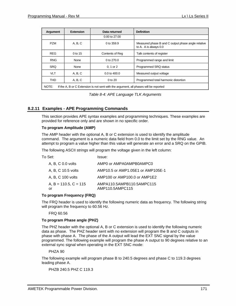
Programming Manual - Rev M Lx \ Ls Series II
Argument Extension Data returned Definition 0.00 to 27.00
PZM A, B, C 0 to 359.9 Measured phase B and C output phase angle relative to A. A is always 0.0
REG 0 to 15 Contents of Reg Talk contents of register
RNG None 0 to 270.0 Programmed range and limit
SRQ None 0, 1 or 2 Programmed SRQ status
VLT A, B, C 0.0 to 400.0 Measured output voltage
THD A, B, C 0 to 20 Programmed total harmonic distortion
NOTE: If the A, B or C Extension is not sent with the argument, all phases will be reported
Table 8-4: APE Language TLK Arguments
8.2.11 ng Commands Examples - APE Programmi
This section provides APE syntax examples and programming techniques. These exampleprovided for reference only and are shown in no specific order.
To program Amplitude (AMP)
The AMP header with the optional A, B or C extension is used to identify the amplitude command. The argument is a numeric data field from 0.0 to the limit set by the RNG value. An
value will generate an error and a SRQ on the GPIB.
s are
B = 110.5, C = 115 AMPA110.5AMPB110.5AMPC115 AMP110.5AMPC115
ension is used to identify the following numeric ata sent with no extension will program the B and C outputs in
the phase A output to 90 degrees relative to an xte the EXT SNC mode:
se B to 240.5 degrees and phase C to 119.3 degrees
PHZB 240.5 PHZ C 119.3
attempt to program a value higher than this
The following ASCII strings will program the voltage given in the left column:
To Set: Issue:
A, B, C 0.0 volts AMP0 or AMPA0AMPB0AMPC0
A, B, C 10.5 volts AMP10.5 or AMP1.05E1 or AMP105E-1
A, B, C 100 volts AMP100 or AMP100.0 or AMP1E2
A, or
To program Frequency (FRQ)
The FRQ header is used to identify the following numeric data as frequency. The following string will program the frequency to 60.56 Hz.
FRQ 60.56
To program Phase angle (PHZ)
The PHZ header with the optional A, B or C extd as phase. The PHZ headerphase with phase A. The phase of the A output will lead the EXT SNC signal by the value programmed. The following example will program e rnal sync signal when operating in
PHZA 90
The following example will program phaleading phase A.
AMETEK Programmable Power Division. 171
Programming Manual - Rev M Lx \ Ls Series II
The PHZA value can be used to control the point of the phase A waveform where the change will occur. The following example will drop the phase A waveform at 90 degrees for 0.017 secondbefore going to 115 volts.
s
115
d. The argument is a numeric data field from 0.0 to the maximum rated current of the
a relative starting CII # symbol. The CAL ramp is not supported on the Ls Series.
C DVM
CAL header is used with the headers VLT, CUR and PWR to calibrate the respective ws the headers to designate a specific
extension is omitted, the calibration coefficients for all measurement will depend on only the value for phase A. The argument is a numeric
operations (DLY)
sed with a parameter that has a numeric argument (examples are AMP, FRQ,
.
to 115 volts with 1.5 volt/.5 sec. steps:
Y .5 STP 1.5 VAL 115
t of 0 is used, the waveform will stop and drop to zero volts at es
PHZA 90 AMP0 DLY .017 VAL
The following example will increase the phase A output voltage to 135 volts for 0.017 seconds starting at the 90 degree point of the waveform. The voltage will return to 115 volts after the tran-sient.
PHZA 90 AMPA 135 DLY .017 VAL 115
To program Current Limit (CRL)
The CRL header with the optional A, B or C extension is used to identify the Current Limit Commanpower system.
The following string will program a current limit of 10.5 amps for all three phases:
CRL 10.5
To program Calibration (CAL)
The CAL header when used alone or followed by the header AMP, in addition to an A, B or C extension, is used to calibrate the programmed output voltage. The argument iscoefficient from 0 to 255 or the ASThe CAL header can be used with a Delay (DLY) command to allow the external calibration Atime to settle. A CAL coefficient can be programmed without a ramp by using only the argument with the CAL header. To program the CAL A coefficient to 55, use the following string:
CALA55
Themeasurement function. An A, B or C extension follomeasurement channel. If the channels will be the same andvalue that represents the expected measured value. It should be equal to an external precision TRMS voltmeter, ammeter or power meter. The following ASCII string will cause the current measurement for phase A to measure the value indicated by a TRMS ammeter standard, 10.12 amps:
CAL CUR A 10.12
To program Ramp or Step
The DLY header is uPHZ, CRL or CAL) in a single step program. The numeric argument is in seconds with four decades of resolution from 0.001 to 9999 seconds. The STP header with VAL may be used with DLY to completely specify a ramp program. The following string will first step the voltage to 125 volts for 2.55 seconds and return to 115 volts
AMP 125 DLY 2.55 VAL 115
The following string will ramp the voltage from 10 volts
AMP 10 DL
When an AMP header with an argumenthe point specified by the PHZ A value. The following ASCII string will stop the waveform at 0 degrefor .01 seconds and return to 115 volts:
PHZ A 0 AMP 0 DLY .01 VAL 115
AMETEK Programmable Power Division. 172
Programming Manual - Rev M Lx \ Ls Series II
The STP header is used to identify a numeric value as the increment or decrement value for a FRQ, CRL, AMP, PHZ or CAL ramp. The following example will ramp all outputs from 130 volts in 1.5
o 10 volts.
ill e,
ration will wait for the Group xe he TRG header is added to the string. The following example will decrement
steps to 100 volts after a Device
FRQ400 STP.1 DLY1 VAL500 STP.5
egister (REG)
used to load the register specified by the following numeric data with the
ltage from 10 to 115 volts with 1 volt/.5 sec steps at 400 Hz into register
VAL115 REG0
e and frequency is maintained at 115 volts
ted by the following ASCII string:
Range (RNG)
c value following the RNG header will also is
ge
volt/.5 sec. steps t
AMP130 DLY.5 STP1.5 VAL10
The header VAL is used to identify the following numeric argument as the final Value of a ramp or step. If the VAL argument is larger than the initial value for the parameter to be ramped, the ramp wincrement with step size defined by STP and DLY. With the VAL argument less than the initial valuthe ramp will decrement from the initial parameter. A ramp or step operation can be started at anytime by the GPIB message Group Execute Trigger (GET). The opeE cute Trigger when tthe output amplitude of phase A only from 120 in .1 volt/.2 sec Trigger.
AMP A 120 DLY.2 STP.1 VAL100 TRG
The following example will simultaneously ramp the Frequency from 400 to 500 Hz at a rate of 0.1 Hz per second and the Amplitude from 5 volts in increments of .5 volts per step:
RNG270 AMP5
A GPIB Service Request will be generated at the end of a ramp if SRQ2 is included in the setup string. The GPIB Group Execute Trigger can stop at a ramp operation anytime.
To program a R
The REG header ispreceding data. The numeric value is from 0 to 15. The PRG header is identical to the REG header and is included to standardize other AC power controllers. The following example will load a ramp program that will step the vo0.
FRQ400 AMP10 DLY.5 STP1
To recall a Register (REC)
The REC header is used to recall previously loaded data from a register identified by the following register number (0 to 15). The following example recalls and outputs the parameters stored in register 0 by an example in previous paragraph:
REC0
The following example recalls the parameters in register 0 and outputs the parameters after the IEEE-488 "GET" message.
REC0 TRG
The following is an example of register linking. The voltagand 60 Hz for 5 seconds and then the program contained in register 0 is recalled and executed. The program is stored in register 1.
FRQ60 AMP115 DLY5 VAL115 REC0 REG1
The program is initia
REC1
To program Voltage
The RNG header is used to select a range. The numeridefine the upper limit for the AMP value. The RNG value will select the higher range if the valuegreater than the lower range value defined by the ALM screen, which is 135 for the standard voltarange. If the range and voltage amplitude are to be programmed by the same data string the RNG header and argument must precede the AMP header or a syntax error will be generated. The
AMETEK Programmable Power Division. 173
Programming Manual - Rev M Lx \ Ls Series II
following example will select the 270 range from the 135/270 range pair with an upper amplitude limit
he with the EXT argument to synchronize the phase A output to an external renced to the sync input with the displacement
EXT
le the sync input.
er with the EXT argument will ak C Power System a slave to another system. The slave will operate at the same eq the master. Phase A of the slave will be related to phase A of the master by the PHZ A
.
and LOCK inputs to the associated slave AC Power System:
CLK EXT
re is no signal at the CLOCK input at the rear panel of the associated power system, the output will go to zero volts.
he er has no argument. When the TRG mnemonic is included in a setup string, it will ela of the string until the bus controller sends the GPIB Device Trigger message. The
tions by including the TRG header with the
t l then be programmed in the remote mode when the
ev eceived.
To program the output Waveform (WVF) (Optional)
The header WVF with the optional A, B or C extension is used to identify the following argument as the Sine Wave (SNW) or Square Wave (SQW) function of the Waveform. The following example will program all outputs to the square wave function.
WVF SQW
The following example will program only output B to the square wave function:
WVFB SQW
To Open (OPN) and Close (CLS) the output relay
The OPN and CLS headers open and close the output relays in the power source. There is no argument associated with these headers. When the OPN or CLS headers is received the output voltage will be programmed to zero volts for 50 milliseconds before the output relays open or close.
of 210 volts.
RNG210
To program External Synchronization (SNC) (optional)
T SNC header is usedsync input. The phase A output will be phase refeequal to the PHZ A value. The following ASCII string will program the phase A output to 0 degree relative to the external sync input and select the external sync mode.
PHZA0 SNC
Sending the ASCII string SNC INT will disab
To program External Clock (CLK) (optional)
The CLK header has an argument of either EXT or INT. The CLK headm e one Afr uency asvalue of the slave.
NOTE The clock option is only available if the associated power systems have the -LKM option
The following ASCII string will enable the CLOCK
NOTE If the
The ASCII string CLK INT will return the slave AC Power System to its programmed frequency.
To Trigger an operation (TRG)
T TRG headd y executionTRG header may also be used to trigger register operastring used to recall a register. The following example will delay execution of the program in register 1 until an IEEE-488 Device Trigger is received:
REC1 TRG
The Trigger mode may also be enabled in the local mode by programming setup parameters withoudepressing the ENT key. The setup values wilD ice Trigger is r
AMETEK Programmable Power Division. 174
Programming Manual - Rev M Lx \ Ls Series II
To program Drop Cycles (DRP)
Command. The argument is a numeric data field from 1 t at
RP B
power-up, IEEE-488 Device Clear or an Amplitude
Clear. The following example
er-up or IEEE-488 Device Clear. A value of 0 the high range. The following example will
pro efault voltage range to the
ALM A 8
To program 1 or 3 Phase Mode (MOD) (optional)
This command is valid only for Ls Series models with the –3 controller and the –MODE option. The MOD header with the required PHS extension is used to identify the mode command. The argument is a 1 or pecify the 1 -phase mod ctively. A mode c by the AC Power System will cause the output voltage to go to the default values. The following string will set the AC Power Systems to the 3-phase mode:
The DRP header is used to identify the Drop to 5. The following string will drop the output voltage for phase B for five complete cycles and star0 degree of the waveform. Note that all drop phase angles are relative to Phase A.
PHZ A 120 D
To program the Default Frequency (FLM A)
The default frequency is the output frequency after power-up or after an IEEE-488 Device Clear. The following example will program the default frequency to 400 Hz.
FLM A 400
To program the default Voltage (INI A)
The default voltage is the output voltage after fault. The following example will program the default voltage to 5 volts.
INI A 5
NOTE: The restrictions on setting initial voltage that applied to the L Series do not apply to the Ls Series so any voltage amplitude - within the selected voltage range - can be set at initialization.
To program the default Current Limit (INI C)
The default current limit is the value after power-up or IEEE-488 Devicewill program the default current limit to 10 amps.
INI C 10
To program the default Voltage Range (ALM A)
The default voltage range is the voltage range after powdesignates the low-range. A value of 8 designates
gram the d high range.
either a 3 to s -phase or 3 e respe hange
MOD PHS 3
AMETEK Programmable Power Division. 175

Programming Manual - Rev M Lx \ Ls Series II
8.2.12 Examples – APE Query Commands
The TLK header will setup the AC Power System to talk data. The TLK header will setup the AC Power System to report a programmed output parameter if the program header is the argument for the heade
To the AC r System to valu , attach a measuremen header as the TLK argument. The measurement headers are VLT, CUR, PWR, APW and PWF with an A, B or C extension and FQM with no extension.
Note: ontrollers, sending a TLK XXX command to the Ls Controller will not cause the front panel to display the measurement screen. This is due to the dif asure versus the L series controller.
The following string r output when it is
For 1-phase systems, all responses will only
, if the TLK argument includes the A, B or C
t if the SRQ2 wing string will cause the Service Request to be
TLK r.
setup Powe report a measured e t
Unlike the California Instruments L Series c
ferent me ment screen layout and organization of the Ls series controller
will setup the AC Power System to measure the phase A powetalk addressed:
TLK PWR A
All arguments for the TLK header are shown in Table 3-13. Table 3-14 shows an example responsefor all TLK arguments with no A, B or C extension.include the phase A value. For 3-phase systemsextension, the response message will be only for the indicated phase.
A GPIB Service Request (SRQ) will be generated at the completion of a measuremenheader is included with the TLK string. The follogenerated when the power system has finished the power factor measurement.
TLK PWF SRQ2
Example talk responses are shown in Table 8-5.
Command Response (Fields separate by SPACE 0x20 characters)
Field A Field B Field C
TLK ALM ALMA0000 B135.0 C270.0
TLK AMP AMPA000.0 B000.0 C000.0
TLK APW APWA1003 B0985 C1507
TLK CFG CFGA0001 B0028 C0120
TLK CLM CLMA11.12 B0002 C0000
TLK CRL CRLA11.12 B11.12 C11.12
TLK CUR CURA06.14 B05.12 C06.71
TLK ELT ELTH0147 M0051 S0033
TLK FLM FLMA0060 B0045 C0550
TLK FQM FQM59.97
TLK FRQ FRQ60.00
TLK CLK CLK INT (*)
TLK SNC SNC INT
TLK PHZ PHZA000.0 B240.0 C120.0
TLK PWF PWFA1.000 B1.000 C1.000
AMETEK Programmable Power Division. 176
Programming Manual - Rev M Lx \ Ls Series II
Command Response (Fields separate by SPACE 0x20 characters)
Field A Field B Field C
TLK PWR PWRA0.737 B0.620 C0.806
TLK PZM PZMA000.0 B242.1 C118.9
TLK REG0 (Contents of REG0)
TLK RNG RNGA 135.0
TLK VLT VLTA120.1 B119.8 C120.0
TLK WVF WVFA SNW B SNW C SNW (*)
Note (*) If function is not enabled, a syntax Error message will be generated.
Table 8-5: Example TALK responses for 3 phase systems
an
an A, B or C extension. When used as an easure the output current in amps.
easured Power (TLK PWR)
PWR may be used as an argument to the header TLK with an A, B or C extension. When used as an asure the output power in watts.
an
gument to the header TLK with an A, B or C extension. When used as an argument, it will set up the AC Power System to measure the Apparent Power output in VA.
To query the red FQM)
FQM may be used as an argument to the header TLK. r this argument. When FQM is used as an argument, it will set up the AC Power System to measure the output frequency in hertz.
To query the measured Phase Angle (TLK PZM)
PZM may be used as an argument with an extension A, B or C for the header TLK. When used as an argument, PZM will set up the AC Power System to measure the phase angle of phase B and C relative to phase A. The measurement is made at the External Sense terminals. Phase A is the reference phase and will always be reported as 000.0 degrees unless the AC Power System is ope g in the ternal
To query the measured Voltage (TLK VLT)
VLT may be used as an argument to the header TLK with an A, B or C extension. When used as argument, it will set up the AC Power System to measure the output voltage with 0.1 volt resolution.
To query the measured Current (TLK CUR)
CUR may be used as an argument to the header TLK withargument, it will set up the AC Power System to m
To query the m
argument, it will set up the AC Power System to me
To query the measured Power Factor (TLK PWF)
PWF may be used as an argument to the header TLK with an A, B or C extension. When used asargument, it will set up the AC Power System to measure the output power factor from 0 to 1.000.
To query the measured Apparent Power (TLK APW)
APW may be used as an ar
measu Frequency (TLK
There are no extensions fo
ratin ex sync mode.
AMETEK Programmable Power Division. 177
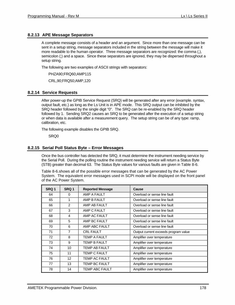
Programming Manual - Rev M Lx \ Ls Series II
8.2.13 APE Message Separators
A complete message consists of a header and an argument. Since more than one message can be sent setup g, me uded in the string between the message will make it more readable to the human operator. Three message semicolon (;) and a space. Since these separators are ignored, they may be dispersed throughout a setup string.
The wing a o exa s with se
A90;FR 0;AM
,90;FR ;AMP
8.2.14 Service Requests
in a strin ssage separators inclseparators are recognized: the comma (,),
follo re tw mples of ASCII string parators:
PHZ Q6 P115
CRL Q50 ,120
After power-up the GPIB Service Request (SRQ) will be generated after any error (example. syntax, outp ult, etc long mode. hibited by the SR der fo d by Q cfollowed by 1. Sending SRQ2 causes an SRQ to be generated after the execution of a setup string or when data is available after a measurement query. Tcalibration, etc.
The following example disables the GPIB SRQ.
SRQ0
8.2.15 Serial Poll Status Byte –
ut fa .) as as the Ls Unit is in APE This SRQ output can be inQ hea llowe the single digit "0". The SR an be re-enabled by the SRQ header
he setup string can be of any type: ramp,
Error Messages
Once the bus controller has detected the SRQ, it must determine the instrument needing service by the Serial Poll. During the polling routine the instrument needing service will return a Status Byte (STB) greater than decimal 63. The Status Byte values for various faults are given in Table 8-6.
Table 8-6.shows all of the possible error messages that can be generated by the AC Power System. The equivalent error messages used in SCPI mode will be displayed on the front panel of the AC Power System.
SRQ 1 SRQ 1 Reported Message Cause 64 0 AMP A FAULT Overload or sense line fault 65 1 AMP B FAULT Overload or sense line fault 66 2 AMP AB FAULT Overload or sense line fault 67 3 AMP C FAULT Overload or sense line fault 68 4 AMP AC FAULT Overload or sense line fault 69 5 AMP BC FAULT Overload or sense line fault 70 6 AMP ABC FAULT Overload or sense line fault 71 7 CRL FAULT Output current exceeds program value 72 8 TEMP A FAULT Amplifier over temperature 73 9 TEMP B FAULT Amplifier over temperature 74 10 TEMP AB FAULT Amplifier over temperature 75 11 TEMP C FAULT Amplifier over temperature 76 12 TEMP AC FAULT Amplifier over temperature 77 13 TEMP BC FAULT Amplifier over temperature 78 14 TEMP ABC FAULT Amplifier over temperature
AMETEK Programmable Power Division. 178
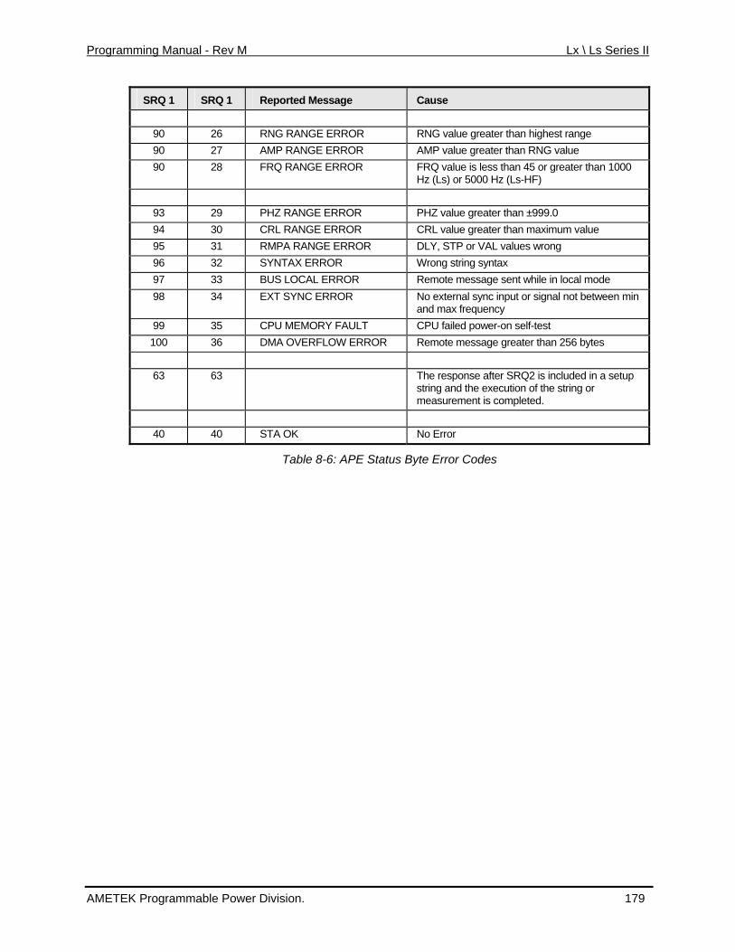
Programming Manual - Rev M Lx \ Ls Series II
SRQ 1 SRQ 1 Reported Message Cause
90 26 RNG RANGE ERROR RNG value greater than highest range 90 27 AMP RANGE ERROR AMP value greater than RNG value 90 28 FRQ RANGE ERROR FRQ value is less than 45 or greater than 1000
Hz (Ls) or 5000 Hz (Ls-HF)
93 29 PHZ RANGE ERROR PHZ value greater than ±999.0 94 30 CRL RANGE ERROR CRL value greater than maximum value 95 31 RMPA RANGE ERROR DLY, STP or VAL values wrong 96 32 SYNTAX ERROR Wrong string syntax 97 33 BUS LOCAL ERROR Remote message sent while in local mode 98 34 EXT SYNC ERROR No external sync input or signal not between min
and max frequency 99 35 CPU MEMORY FAULT CPU failed power-on self-test 100 36 DMA OVERFLOW ERROR Remote message greater than 256 bytes
63 63 The response after SRQ2 is included in a setup
string and the execution of the string or measurement is completed.
40 40 STA OK No Error
Table 8-6: APE Status Byte Error Codes
AMETEK Programmable Power Division. 179
Programming Manual - Rev M Lx \ Ls Series II
8.2.1 End of String Delimiter 6
The End of String (EOS) delimiter recognized by the Ls AC Power source in APE mode is the ASLine Feed (LF). Carriage Return (CR) followed by Line Feed may also be used for EOS. The Identify (EOI) IEEE-488 message END will also be recognized. The END message is sent bythe IEEE-488 End or Identify line true with the last da
CII End or
setting ta byte.
8.2.17 Group Execute Trigger - GET
The trigger mode is enabled when the mnemonic TRG is added to a setup string. The trigger command may be inserted anywhere in the string. When the mnemonic is detected, it will delay execution of the new setup values until the GPIB Device Trigger is sent by the bus controller.
A GPIB Device Trigger will also terminate a programmed ramp or other program.
The following setup string will recall the values from register 9 and delay execution until the GET message is received. (Note: GET is the abbreviation for the GPIB Group Execute Trigger messageand does not represent a series of ASCII characters.
REC9 TRG
AMETEK Programmable Power Division. 180
Programming Manual - Rev M Lx \ Ls Series II
8.3 ABLE Command Language (Atlas Based Language Extension)
The ABLE (Atlas Based Language Extension) command language syntax is available on Ls S (Firm rovides backward compatibility with Elager Series 9012 single phase (PIP9012) and Series 9023 ( phas
T undled is present, units of similtest systems running programs written using the ABLE syntax. The presence of this option can b by usi he presence of the ABLE option is indicated by the “LANG” option sto ed; the BLE mode, the IEEE488.2commands.
T the m nguage is still available as well although not at the same time. The power source can be configured to p her mo
the fron ATION screen using the MENU key. In the CONFIGURATION screen, select the LANG SPCI, ABLE
When operating over g commands depending on the present mode of operation to switch between language modes.
eries models. ware revision must be 1.61 or higher). The ABEL language p
PIP9023) three e programmable controllers.
his option is b on the Ls Series with the GPIB interface option. If the GPIB optionsar power and voltage rating can be used to replace PIP controller units in
e determined ng the *OPT? or SYST:CONF? Command queries. Tring in the response to this query. If the –ABL
power source can be switched from SCPI mode to ABLE mode. In A common commands such as *IDN? Are still available but not SCPI
ption is install
his section of anual covers the ABLE syntax. Note that the SCPI command la
ower up in eit de of operation. The procedure is as follows:
• From t panel, select the CONFIGURfield. This field can be toggled between
or APE using the shuttle knob.
the bus, send the followin
Present Mode To change to other language mode, send:
ABLE mode SCPI
SCPI mode SYST:LANG ABLE
Table 8-7: ABLE to SCPI mode change commands
8.3.1 Introduction
Remote programming through the IEEE-488 Interface (GPIB) consists of sending the unit a he prop meter and the numerical value if an argument is required.
8.3.2 ABLE Language details
ddress and t er ASCII alphanumeric characters to identify the para
T e following comma s areh nd supported by the –ABL option.
SYNTAX DESCRIPTION
VOLTA <n> Programs voltage on phase A. (9023)
VOLTB <n> Programs voltage on phase B. (9023)
VOLTC <n> Programs voltage on phase C. (9023)
VOLTS <n> Programs voltage on all phases (9023) or on phase A on (9012)
CURL <n> d by numeric value. (9012) Set the current limit value followe
AMETEK Programmable Power Division. 181
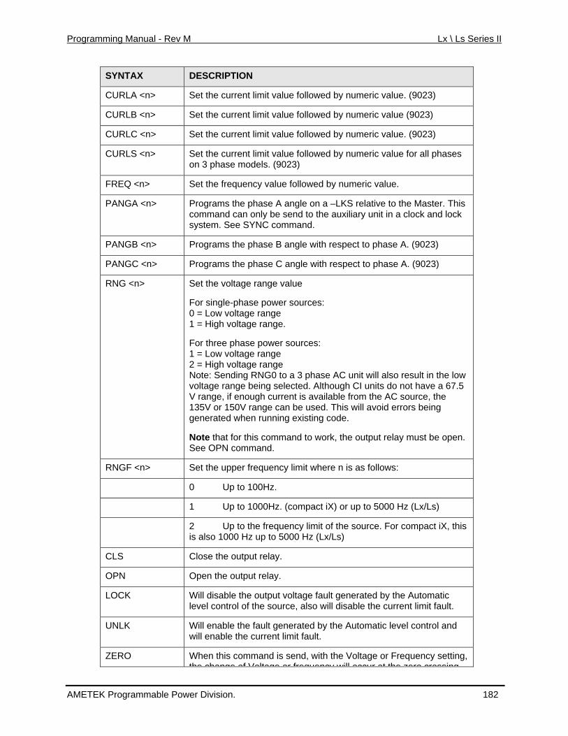
Programming Manual - Rev M Lx \ Ls Series II
SYNTAX DESCRIPTION
CURLA <n> Set the current limit value followed by numeric value. (9023)
CURLB <n> current limit value followed by numeric value (9023) Set the
CURLC <n> Set the current limit value followed by numeric value. (9023)
CURLS <n> ses on 3 phase models. (9023) Set the current limit value followed by numeric value for all pha
FREQ <n> Set the frequency value followed by numeric value.
PANGA <n> lock
Programs the phase A angle on a –LKS relative to the Master. This command can only be send to the auxiliary unit in a clock and system. See SYNC command.
PANGB <n> Programs the phase B angle with respect to phase A. (9023)
PANGC <n> Programs the phase C angle with respect to phase A. (9023)
RNG <n>
Note: Sending RNG0 to a 3 phase AC unit will also result in the low .5
Set the voltage range value
For single-phase power sources: 0 = Low voltage range 1 = High voltage range.
For three phase power sources: 1 = Low voltage range 2 = High voltage range
voltage range being selected. Although CI units do not have a 67V range, if enough current is available from the AC source, the 135V or 150V range can be used. This will avoid errors being generated when running existing code.
Note that for this command to work, the output relay must be open. See OPN command.
RNGF <n> Set the upper frequency limit where n is as follows:
0 Up to 100Hz.
AMETEK Programmable Power Division. 182
1 Up to 1000Hz. (compact iX) or up to 5000 Hz (Lx/Ls)
2 Up to the frequency limit ofis also 1000 Hz up to 5000 Hz (Lx/L
the source. For compact iX, this s)
CLS Close the output relay.
OPN Open the output relay.
LOCK Will disable the output voltage fault generated by the Automatic sable the current limit fault. level control of the source, also will di
UNLK Will enable the fault generated by thewill enable the current limit fault.
Automatic level control and
ZERO When this command is send, with the Voltage or Frequency setting, the change of Voltage or frequency will occur at the zero crossing
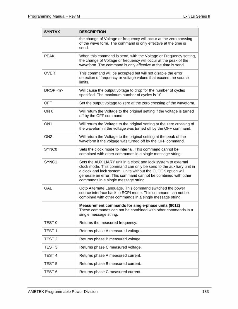
Programming Manual - Rev M Lx \ Ls Series II
SYNTAX DESCRIPTION
the change of Voltage or frequency wof the wave form. The command is only effective at the time is
ill occur at the zero crossing
send.
PEAK When this command is send, with the Voltage or Frequency setting, the change of Voltage or frequency will occur at the peak of the
d. waveform. The command is only effective at the time is sen
OVER ccepted but will not disable the error detection of frequency or voltage values that exceed the source This command will be a
limits.
DROP <n> for the number of cycles Will cause the output voltage to dropspecified. The maximum number of cycles is 10.
OFF Set the output voltage to zero at the zero crossing of the waveform.
ON 0 Will return the Voltage to the original setting if the voltage is turned off by the OFF command.
ON1 Will return the Voltage to the original setting at the zero crossing of ed off by the OFF command. the waveform if the voltage was turn
ON2 Will return the Voltage to the originalwaveform if the voltage was turned o
setting at the peak of the ff by the OFF command.
SYNC0 Sets the clock mode to internal. This command cannot be . combined with other commands in a single message string
SYNC1 Sets the AUXILIARY unit in a clock and lock system to exteclock mode. This command can only be send to the auxilia
rnal ry unit in
out the CLOCK option will
co d
a clock and lock system. Units withgenerate an error. This command cannot be combined with other
mman s in a single message string.
GAL Goto Alternate Language. This command switched the power source interface back to SCPI mode. This command can not be combined with other commands in a single message string.
Measurement commands for single-phase units (9012) These commands can not be combined with other commands in a single message string.
TEST 0 Returns the measured frequency.
TEST 1 Returns phase A measured voltage.
TEST 2 Returns phase B measured voltage.
TEST 3 Returns phase C measured voltage.
TEST 4 Returns phase A measured current.
TEST 5 Returns phase B measured current.
TEST 6 Returns phase C measured current.
AMETEK Programmable Power Division. 183
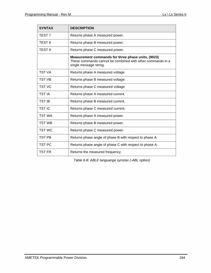
Programming Manual - Rev M Lx \ Ls Series II
SYNTAX DESCRIPTION
TEST 7 Returns phase A measured power.
TE ST 8 Returns phase B measured power.
TEST Returns phase C measured power. 9
ther commands in a
single message string.
Measurement commands for three phase units, (9023) These commands cannot be combined with o
TST VA Returns phase A measured voltage
TST VB Returns phase B measured voltage
TST VC Returns phase C measured voltage
TST IA Returns phase A measured current.
TST IB Returns phase B measured current.
TST IC Returns phase C measured current.
TST WA Returns phase A measured power.
TST WB Re turns phase B measured power.
TST WC Re turns phase C measured power.
TST PB Returns phase angle of phase B with respect to phase A.
TST PC Returns phase angle of phase C with respect to phase A.
TST FR Returns the measured frequency.
Table 8-8: ABLE languange synstax (-ABL option)
AMETEK Programmable Power Division. 184
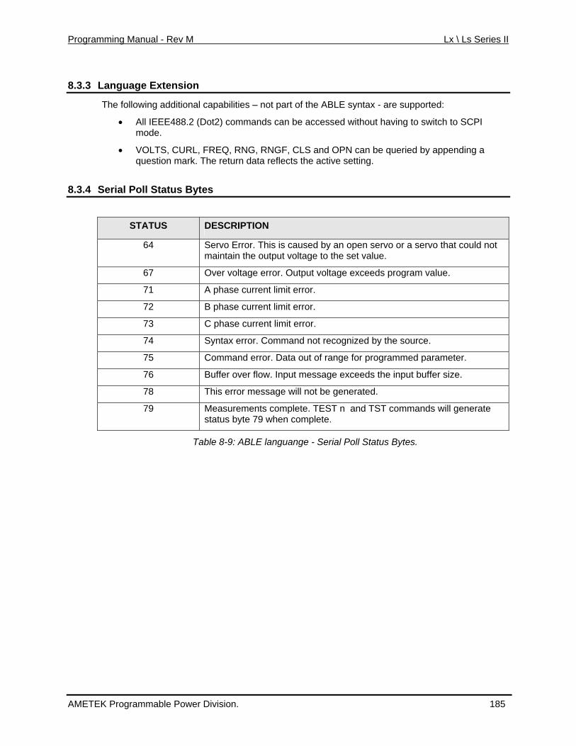
Programming Manual - Rev M Lx \ Ls Series II
8.3.3 Language Extension
The following additional capabilities – not part of the ABLE syntax - are supported:
• All IEEE488.2 (Dot2) commands can be accessed without having to switch to SCPI mode.
• VOLTS, CURL, FREQ, RNG, RNGF, CLS and OPN can be queried by appending a question mark. The return data reflects the active setting.
erial Poll Status Bytes 8.3.4 S
STATUS DESCRIPTION
64 Servo Error. This is caused by an open servo or a servo that could not maintain the output voltage to the set value.
67 Over voltage error. Output voltage exceeds program value.
71 A phase current limit error.
72 B phase current limit error.
73 C phase current limit error.
74 Syntax error. Command not recognized by the source.
75 Command error. Data out of range for programmed parameter.
76 Buffer over flow. Input message exceeds the input buffer size.
78 This error message will not be generated.
79 Measurements complete. TEST n and TST commands will generate status byte 79 when complete.
Table 8-9: ABLE languange - Serial Poll Status Bytes.
AMETEK Programmable Power Division. 185
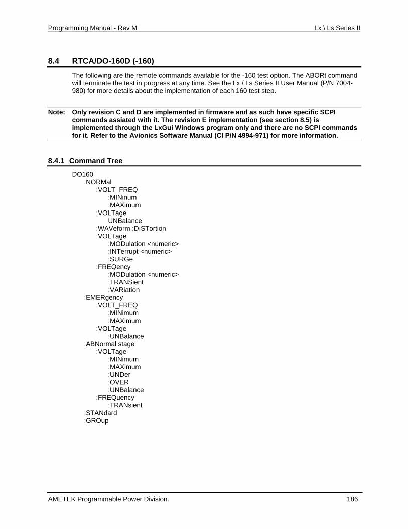
Programming Manual - Rev M Lx \ Ls Series II
8.4 RTCA/DO-160D (-160)
The following are the remote commands available for the -160 test option. The ABORt command
Note: e specific SCPI
will terminate the test in progress at any time. See the Lx / Ls Series II User Manual (P/N 7004-980) for more details about the implementation of each 160 test step.
Only revision C and D are implemented in firmware and as such havcommands as ith it. Timplemented through the LxGui Window
siated w he revision E implementation (see section 8.5) is s program only and there are no SCPI commands
for it. Refer to the Avionics Software Manual (CI P/N 4994-971) for more information.
8.4.1 Command Tree
DO160 :NORMal :VOLT_FREQ :MINinum
:VOLTage
:MODulation <numeric>
:VOLT_FREQ
:ABNormal stage
:MAXimum :VOLTage UNBalance :WAVeform :DISTortion
:MODulation <numeric> :INTerrupt <numeric> :SURGe
ency :FREQ
:TRANSient :VARiation :EMERgency
:MINimum :MAXimum :VOLTage :UNBalance
:VOLTage :MINimum :MAXimum :UNDer :OVER :UNBalance :FREQuency :TRANsient :STANdard :GROup
AMETEK Programmable Power Division. 186
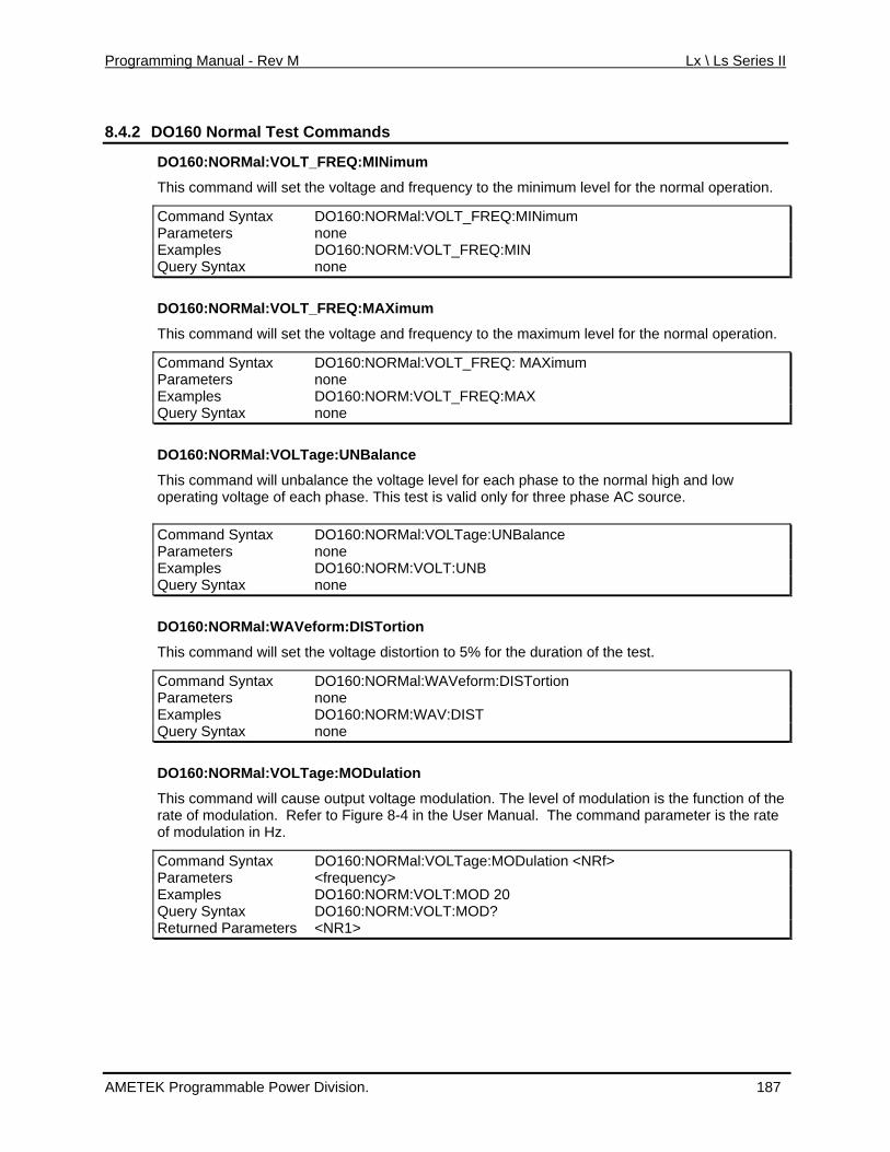
Programming Manual - Rev M Lx \ Ls Series II
8.4.2 DO160 Normal Test Commands
DO160:NORMal:VOLT_FREQ:MINimum
This command will set the voltage and frequency to the minimum level for the normal operation.
Command Syntax DO160:NORMal:VOLT_FREQ:MINimum Parameters none Examples DO160:NORM:VOLT_FREQ:MIN Query Syntax none
O160:NORMal:VOLT_FREQ:MAXimum
d frequency to the maximum level for the normal operation.
D
This command will set the voltage an
Command Syntax DO160:NORMal:VOLT_FREQ: MAXimum Parameters none Examples DO160:NORM:VOLT_FREQ:MAX Query Syntax none
al:VOLTa Balance
his command will unbalance the voltage level for each phase to the normal high and low valid only for three phase AC source.
DO160:NORM ge:UN
Toperating voltage of each phase. This test is
Command Syntax DO160:NORMal:VOLTage:UNBalance Parameters none Examples DO160:NORM:VOLT:UNB Query Syntax none
th e distortion to 5% for the duration of the test.
ommand Syntax DO160:NORMal:WAVeform:DISTortion
DO160:NORMal:WAVeform:DISTortion
This command will set e voltag
CParameters none Examples DO160:NORM:WAV:DIST Query Syntax none
dulation is the function of the
ommand Syntax DO160:NORMal:VOLTage:MODulation <NRf>
DO160:NORMal:VOLTage:MODulation
This command will cause output voltage modulation. The level of moion. Refe gure 8-4 in the User Manual. The command parameter is the rate rate of modulat r to Fi
of modulation in Hz.
CParameters <frequency> Examples DO160:NORM:VOLT:MOD 20 Query Syntax DO160:NORM:VOLT:MOD? Returned Parameters <NR1>
AMETEK Programmable Power Division. 187
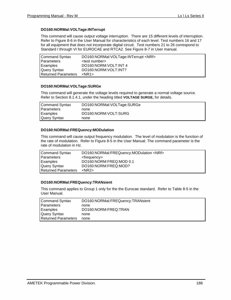
Programming Manual - Rev M Lx \ Ls Series II
DO160:NORMal:VOLTage:INTerrupt
This command will cause output voltage interruption. There are 15 different levels of interruption. Refer to Figure
8-6 in the User Manual for characteristics of each level. Test numbers 16 and 17
in User manual.
f>
for all equipment that does not incorporate digital circuit. Test numbers 21 to 26 correspond to Standard I through r EUROCAE and RTCA2. See Figure 8-7 VI fo
Command Syntax DO160:NORMal:VOLTage:INTerrupt <NRParameters <test number> Examples DO160:NORM:VOLT:INT 4 Query Syntax DO160:NORM:VOLT:INT? Returned Parameters <NR1>
DO160:NORMal:VOLTage:SURGe
This command will generate the voltage levels required to generate a normal voltage source. Refer to Section 8.1.4.1, under the heading titled VOLTAGE SURGE, for details.
Command Syntax DO160:NORMal:VOLTage:SURGe Parameters none Examples DO160:NORM:VOLT:SURG Query Syntax none
DO160:NORMal:FREQuency:MODulation
This command will cause output frequency modulation. The level of modulation is the function of the rate of modulation. Refer to Figure 8-5 in the User Manual. The command parameter is the rate of modulation in Hz.
Command Syntax DO160:NORMal:FREQuency:MODulation <NRf> Parameters <frequency> Examples DO160:NORM:FREQ:MOD 0.1 Query Syntax DO160:NORM:FREQ:MOD? Returned Parameters <NR2>
DO160:NORMal:FREQuency:TRANsient
This command applies to Group 1 only for the the Eurocae standard. Refer to Table 8-5 in the User Manual.
Command Syntax DO160:NORMal:FREQuency:TRANsient Parameters none Examples DO160:NORM:FREQ:TRAN Query Syntax none Returned Parameters none
AMETEK Programmable Power Division. 188
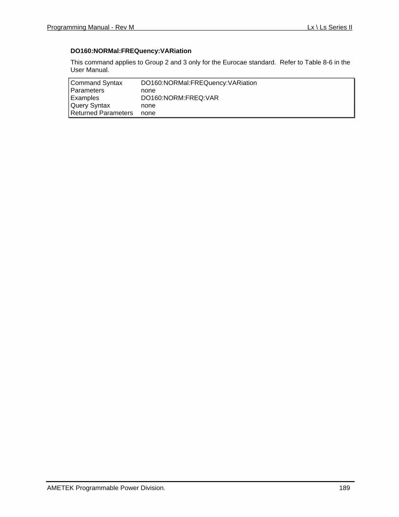
Programming Manual - Rev M Lx \ Ls Series II
DO160:NORMal:FREQuency:VARiation
nly for the Eurocae standard. Refer to Table 8-6 in the This command applies to Group 2 and 3 oUser Manual.
Command Syntax DO160:NORMal:FREQuency:VARiation Parameters none Examples DO160:NORM:FREQ:VAR Query Syntax none Returned Parameters none
AMETEK Programmable Power Division. 189
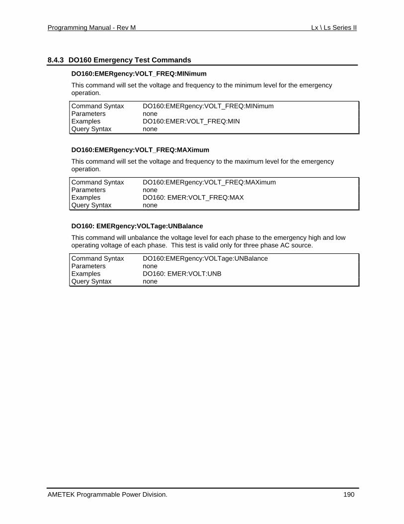
Programming Manual - Rev M Lx \ Ls Series II
8.4.3 DO160 Emergency Test Commands
DO160:EMERgency:VOLT_FREQ:MINimum
ency
cy:VOLT_FREQ:MINimum
This command will set the voltage and frequency to the minimum level for the emergoperation.
Command Syntax DO160:EMERgenParameters none Examples DO160:EMER:VOLT_FREQ:MIN Query Syntax none
DO160:EMERgency:VOLT_FREQ:MAXimum
This command will set the voltage and frequency to the maximum level for the emergency operation.
Command Syntax DO160:EMERgency:VOLT_FREQ:MAXimum Parameters none Examples DO160: EMER:VOLT_FREQ:MAX Query Syntax none
DO160: EMERgency:VOLTage:UNBalance
This command will unbalance the voltage level for each phase to the emergency high and low operating voltage of each phase. This test is valid only for three phase AC source.
ce Command Syntax DO160:EMERgency:VOLTage:UNBalanParameters none Examples DO160: EMER:VOLT:UNB Query Syntax none
AMETEK Programmable Power Division. 190
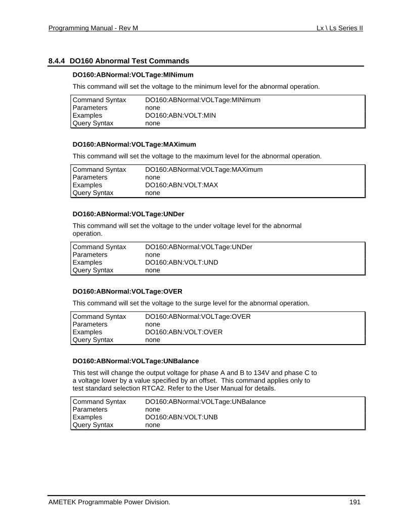
Programming Manual - Rev M Lx \ Ls Series II
8.4.4 DO160 Abnormal Test Commands
DO160:ABNormal:VOLTage:MINimum
set th mal operation. This command will e voltage to the minimum level for the abnor
Command Syntax DO160:ABNormal:VOLTage:MINimum Parameters none Examples DO160:ABN:VOLT:MIN Query Syntax none
imum
et the voltage to the maximum level for the abnormal operation.
DO160:ABNormal:VOLTage:MAX
This command will s
Command Syntax DO160:ABNormal:VOLTage:MAXimum Parameters none Examples DO160:ABN:VOLT:MAX Query Syntax none
DO160:ABNormal:VOLTage:UNDer
This command will e voltage to the undset th er voltage level for the abnormal
operation.
Command Syntax DO160:ABNormal:VOLTage:UNDerParameters none Examples DO160:ABN:VOLT:UND Query Syntax none
DO160:ABNormal:VOLTage:OVER
This command will set the voltage to the surge level for the abnormal operation.
Command Syntax DO160:ABNormal:VOLTage:OVER Parameters none Examples DO160:ABN:VOLT:OVER Query Syntax none
DO160:ABNormal:VOLTage:UNBalance
This test will change the output voltage for phase A and B to 134V and phase C to a voltage lower by a value specified by an offset. This command applies only to test standard selection RTCA2. Refer to the User Manual for details.
Command Syntax DO160:ABNormal:VOLTage:UNBalance Parameters none Examples DO160:ABN:VOLT:UNB Query Syntax none
AMETEK Programmable Power Division. 191
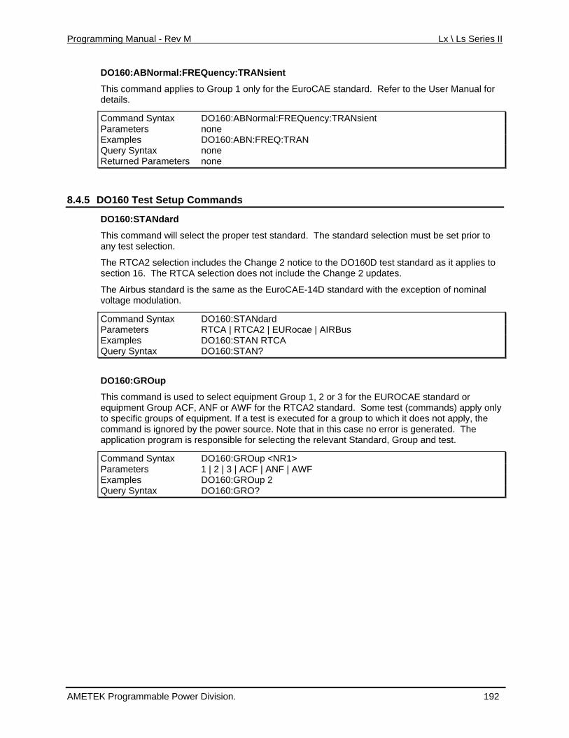
Programming Manual - Rev M Lx \ Ls Series II
DO160:ABNormal:FREQuency:TRANsient
the EuroCAE standard. Refer to the User Manual for This command applies to Group 1 only for details.
Command Syntax DO160:ABNormal:FREQuency:TRANsient Parameters none Examples DO160:ABN:FREQ:TRAN Query Syntax none Returned Parameters none
8.4.5 DO160 Test Setup Commands
DO160:STANdard
This command will select the proper test standard. The standard selection must be set prior to any test selection.
The RTCA2 selection includes the Change 2 notice to the DO160D test standard as it applies to section 16. The RTCA selection does not include the Change 2 updates.
The Airbus standard is the same as the EuroCAE-14D standard with the exception of nominal voltage modulation.
Command Syntax DO160:STANdard Parameters RTCA | RTCA2 | EURocae | AIRBus Examples DO160:STAN RTCA Query Syntax DO160:STAN?
DO160:GROup
This command is used to select equipment Group 1, 2 or 3 for the EUROCAE standard or equipment Group ACF, ANF or AWF for the RTCA2 standard. Some test (commands) apply only to specific groups of equipment. If a test is executed for a group to which it does not apply, the command is ignored by the power source. Note that in this case no error is generated. The application program is responsible for selecting the relevant Standard, Group and test.
Command Syntax DO160:GROup <NR1> Parameters 1 | 2 | 3 | ACF | ANF | AWF Examples DO160:GROup 2 Query Syntax DO160:GRO?
AMETEK Programmable Power Division. 192

Programming Manual - Rev M Lx \ Ls Series II
8.5 RTCA/DO160 Rev E Test Option
Revison E of the RTCA/DO160 AC power section test standard is implemented through thprovided LxGui windows program and can be accessed if the -160 option. As such, there a
e re no
SCP ofor r
I c mmands that apply to this revision. See the 7004-980 Lx and Ls Series II User Manual ope ation information.
AMETEK Programmable Power Division. 193
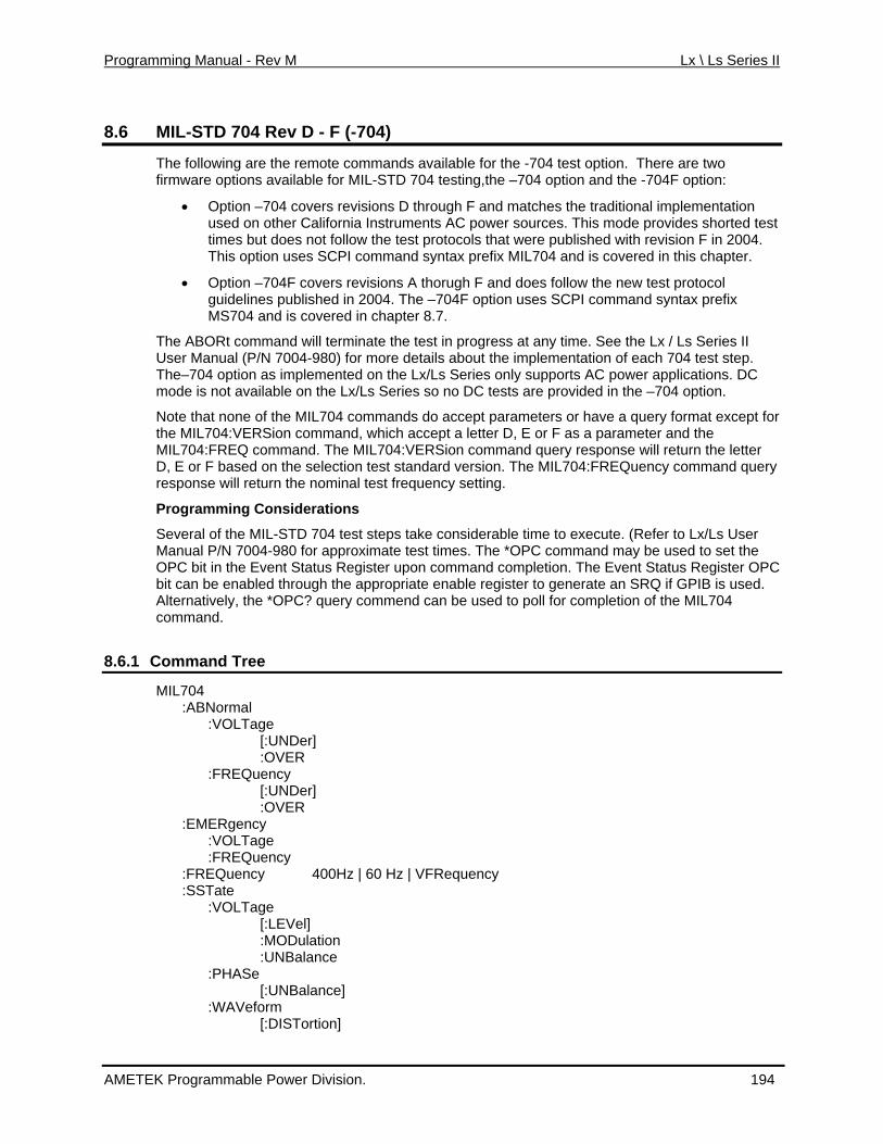
Programming Manual - Rev M Lx \ Ls Series II
8.6 04 (-704) MIL-STD 7 Rev D - F
The following are the remote commands available for the -704 test option. There are two ble for MIL-STD 704 testing,the –704 option and the -704F option:
n – revisions D through F and matches the traditional implementation fornia Instruments AC power sources. This mode provides shorted test
ollow the test protocols that were published with revision F in 2004. opt PI command syntax prefix MIL704 and is covered in this chapter.
ers revisions A thorugh F and does follow the new test protocol guidelines published in 2004. The –704F option uses SCPI command syntax prefix
chapter 8.7.
nd will terminate the test in progress at any time. See the Lx / Ls Series II
Lx/Ls Series so no DC tests are provided in the –704 option.
ands do accept parameters or have a query format except for n co ept a letter D, E or F as a parameter and the man Sion command query response will return the letter
he MIL704:FREQuency command query
everal of the MIL-STD 704 test steps take considerable time to execute. (Refer to Lx/Ls User for approximate test times. The *OPC command may be used to set the
4
8.6.1 C
firmware options availa
• Optio 704 coveris
used on other Cal butimes t does not f
This ion uses SC
• Option –704F cov
MS704 and is covered in
The ABORt commaUser Manual (P/N 7004-980) for more details about the implementation of each 704 test step. The–704 option as implemented on the Lx/Ls Series only supports AC power applications. DC mode is not available on the
Note that none of the MIL704 commthe MIL704:VERSio mmand, which acc
Q com L704:VERMIL704:FRE d. The MID, E or F based on the selection test standard version. T
eturn the n uency setting. response will r ominal test freq
Programming Considerations
SManual P/N 7004-980 OPC bit in the Event Status Register upon command completion. The Event Status Register OPC bit can be enabled through the appropriate enable register to generate an SRQ if GPIB is used. Alternatively, the *OPC? query commend can be used to poll for completion of the MIL70command.
ommand Tree
MIL704 :ABNormal :VOLTage [:UNDer] :OVER :FREQuency [:UNDer] :OVER :EMERgency :VOLTage :FREQuency :FREQuency 400Hz | 60 Hz | VFRequency :SSTate :VOLTage [:LEVel] :MODulation :UNBalance :PHASe [:UNBalance] :WAVeform [:DISTortion]
AMETEK Programmable Power Division. 194
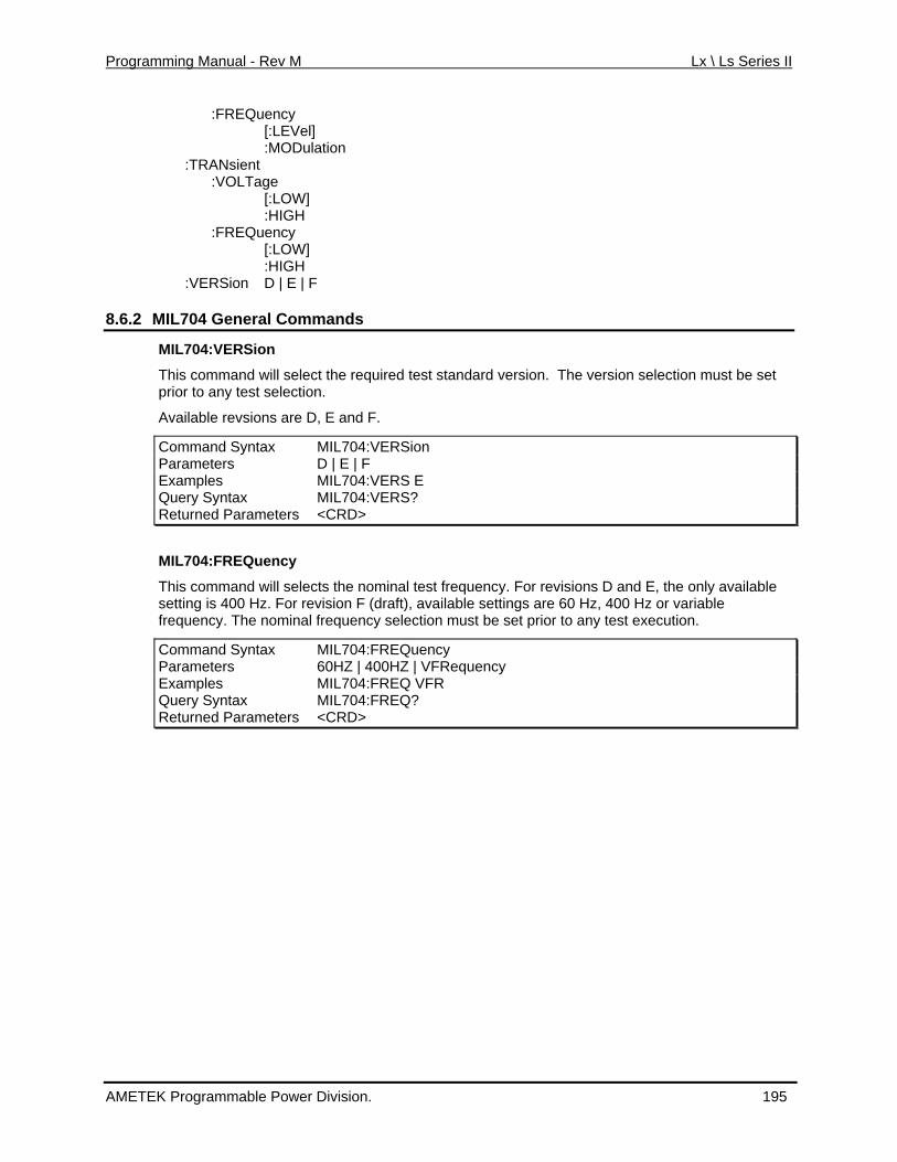
Programming Manual - Rev M Lx \ Ls Series II
:FREQuency
:HIGH :VERSion D | E | F
8.6.2 MIL704 General Commands
[:LEVel] :MODulation :TRANsient :VOLTage [:LOW] :HIGH :FREQuency [:LOW]
MIL704:VERSion
This command will select the required test standard version. The version selection must be set
ns are D F.
prior to any test selection.
Available revsio , E and
Command Syntax MIL704:VERSion Parameters D | E | F Examples MIL704:VERS E Query Syntax MIL704:VERS? Returned Parameters <CRD>
MIL704:FREQuency
This command ts the will selec nominal test frequency. For revisions D and E, the only available setting is 400 Hz. For revision F (draft), available settings are 60 Hz, 400 Hz or variable
tion must be set prior to any test execution. frequency. The nominal frequency selec
Command Syntax MIL704:FREQuency Parameters 60HZ | 400HZ | VFRequency Examples MIL704:FREQ VFR Query Syntax MIL704:FREQ? Returned Parameters <CRD>
AMETEK Programmable Power Division. 195
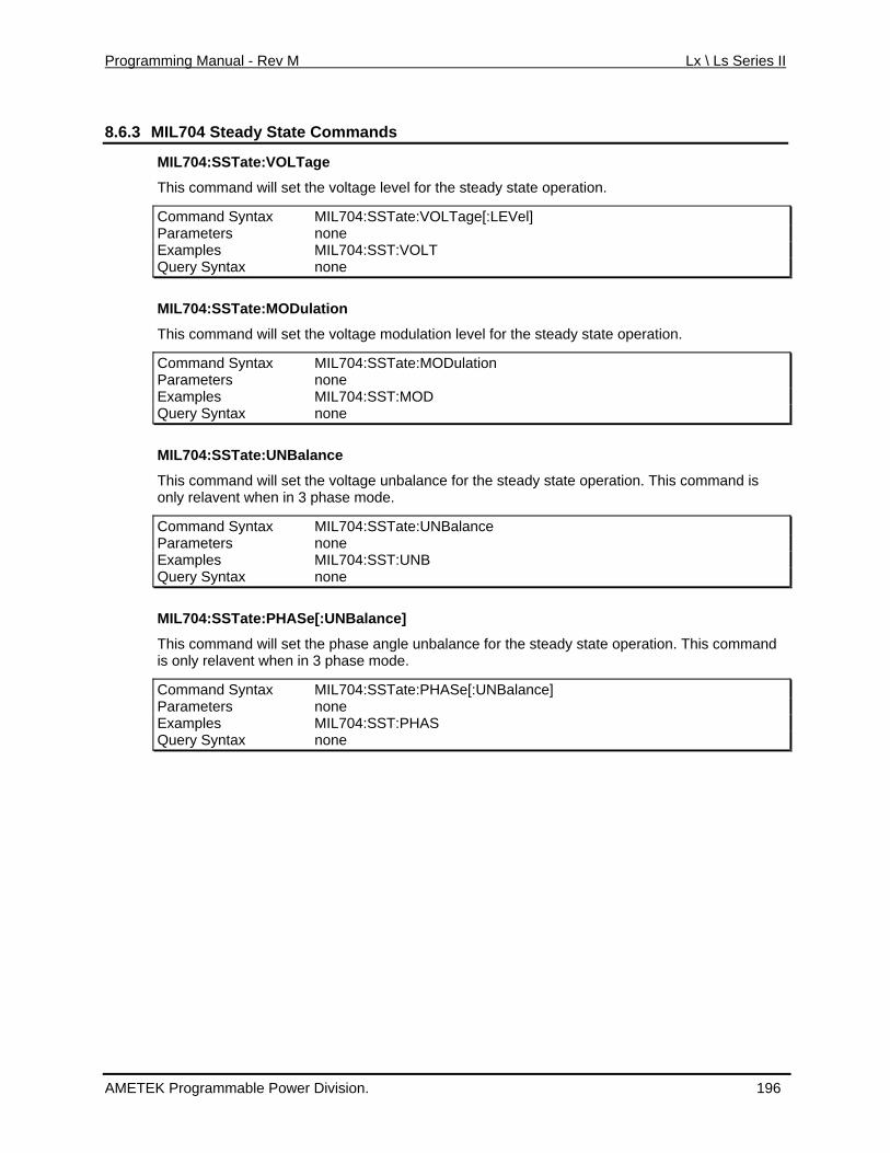
Programming Manual - Rev M Lx \ Ls Series II
8.6.3 MIL704 Steady State Commands
MIL704:SSTate:VOLTage
This command will set the voltage level for the steady state operation.
tax 4:SSTate:VOLTage[:LEVel] Command Syn MIL70Parameters none Examples MIL704:SST:VOLT Query Syntax none
ion level for the steady state operation.
tax 4:SSTate:MODulation
MIL704:SSTate:MODulation
This command will set the voltage modulat
Command Syn MIL70Parameters none Examples MIL704:SST:MOD Query Syntax none
ce for the steady state operation. This command is
Command Syntax MIL704:SSTate:UNBalance
MIL704:SSTate:UNBalance
This command will set the voltage unbalanonly relavent when in 3 phase mode.
Parameters none Examples MIL704:SST:UNB Query Syntax none
]
MIL704:SSTate:PHASe[:UNBalance]
This command will set the phase angle unbalance for the steady state operation. This command is only relavent when in 3 phase mode.
Command Syntax MIL704:SSTate:PHASe[:UNBalanceParameters none Examples MIL704:SST:PHAS Query Syntax none
AMETEK Programmable Power Division. 196
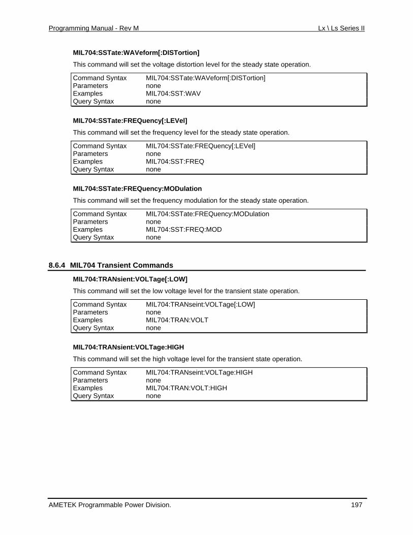
Programming Manual - Rev M Lx \ Ls Series II
MIL704:SSTate:WAVeform[:DISTortion]
This command will set the voltage distortion level for the steady state operation.
Command Syntax MIL704:SSTate:WAVeform[:DISTortion] Parameters none Examples MIL704:SST:WAV Query Syntax none
MIL704:SSTate:FREQuency[:LEVel]
This command will set the frequency level for the steady state operation.
Command Syntax MIL704:SSTate:FREQuency[:LEVel] Parameters none Examples MIL704:SST:FREQ Query Syntax none
MIL704:SSTate:FREQuency:MODulation
lation for the steady state operation.
FREQuency:MODulation
This command will set the frequency modu
Command Syntax MIL704:SSTate:Parameters none Examples MIL704:SST:FREQ:MOD Query Syntax none
.6.4 MIL704 Transient Commands 8
MIL704:TRANsient:VOLTage[:LOW]
This command will set the low voltage level for the transient state operation.
Command Syntax MIL704:TRANseint:VOLTage[:LOW] Parameters none Examples MIL704:TRAN:VOLT Query Syntax none
MIL704:TRANsient:VOLTage:HIGH
This command will set the high voltage level for the transient state operation.
Command Syntax MIL704:TRANseint:VOLTage:HIGH Parameters none Examples MIL704:TRAN:VOLT:HIGH Query Syntax none
AMETEK Programmable Power Division. 197
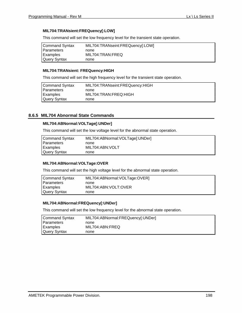
Programming Manual - Rev M Lx \ Ls Series II
MIL704:TRANsient:FREQuency[:LOW]
This command will set the low frequency level for the transient state operation.
Command Syntax MIL704:TRANseint:FREQuency[:LOW] Parameters none Examples MIL704:TRAN:FREQ Query Syntax none
MIL704:TRANsient: FREQuency:HIGH
level for the transient state operation.
RANseint:FREQuency:HIGH
This command will set the high frequency
Command Syntax MIL704:TParameters none Examples MIL704:TRAN:FREQ:HIGH Query Syntax none
.6.5 MIL704 Abnormal State Commands 8
MIL704:ABNormal:VOLTage[:UNDer]
r]
This command will set the low voltage level for the abnormal state operation.
Command Syntax MIL704:ABNormal:VOLTage[:UNDeParameters none Examples MIL704:ABN:VOLT Query Syntax none
MIL704:ABNormal:VOLTage:OVER
This command will set the high voltage level for the abnormal state operation.
Command Syntax MIL704:ABNormal:VOLTage:OVER] Parameters none Examples MIL704:ABN:VOLT:OVER Query Syntax none
MIL704:ABNormal:FREQuency[:UNDer]
This command will set the low frequency level for the abnormal state operation.
Command Syntax MIL704:ABNormal:FREQuency[:UNDer] Parameters none Examples MIL704:ABN:FREQ Query Syntax none
AMETEK Programmable Power Division. 198

Programming Manual - Rev M Lx \ Ls Series II
MIL704:ABNormal:FREQuency:OVER
y level for the abnormal state operation. This command will set the high frequenc
Command Syntax MIL704:ABNormal:FREQuency:OVER] Parameters none Exa lmp es MIL704:ABN:FREQ:OVER Que Sry yntax none
8.6.6 MIL704 Emergeny State Commands
MIL704:EMERgency:VOLTage
This command will set the voltage level for the emergency state operation.
Command Syntax MIL704:EMERgency:VOLTage Parameters none Examples MIL704:EMER:VOLT Query Syntax none
Command Syntax MIL704:EMERgency:FREQuency
MIL704:EMERgency:FREQuency
This command will set the frequency level for the emergency state operation.
Parameters none Examples MIL704:EMER:FREQ Query Syntax none
AMETEK Programmable Power Division. 199
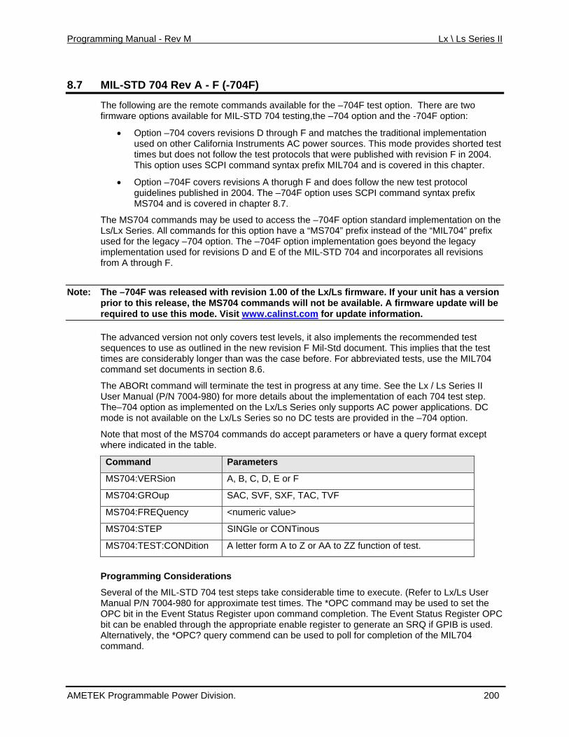
Programming Manual - Rev M Lx \ Ls Series II
8.7 MIL-STD 704 Rev A - F (-704F)
The following are the remote commands available for the –704F test option. There are two ailable for MIL-STD 704 testing,the –704 option and the -704F option:
revisions D through F and matches the traditional implementation on ia Instruments AC power sources. This mode provides shorted test bu follow the test protocols that were published with revision F in 2004. opt PI command syntax prefix MIL704 and is covered in this chapter.
isions A thorugh F and does follow the new test protocol lin 4. The –704F option uses SCPI command syntax prefix
04 s c apter 8.7.
om ds to access the –704F option standard implementation on the Al ma ave a “MS704” prefix instead of the “MIL704” prefix eg 704 4F option implementation goes beyond the legacy
evisions D and E of the MIL-STD 704 and incorporates all revisions
Note: as se ion 1.00 of the Lx/Ls firmware. If your unit has a version
firmware options av
• Optio 704 coversn –used other Californtimes t does notThis ion uses SC
• Option –704F covers revguide es published in 200MS7 and i overed in ch
The MS704 c man may be usedLs/Lx Series. l com nds for this option hused for the l acy – option. The –70implementation used for rfrom A through F.
The –704F w relea d with revisprior to this ease e MS704 comman
de. Visit www.carel , th ds will not be available. A firmware update will be
o linst.comrequired to use this m for update information.
The advance ersion not od v nly covers test levels, it also implements the recommended test us n the new revision F Mil-Std document. This implies that the test sid er than was the case before. For abbreviated tests, use the MIL704
t do section 8.6.
will terminate the test in progress at any time. See the Lx / Ls Series II 7004-980) for more details about the implementation of each 704 test step.
plemented on the Lx/Ls Series only supports AC power applications. DC e Lx/Ls Series so no DC tests are provided in the –704 option.
st o ommands do accept parameters or have a query format except ted .
sequences to e as outlined itimes are con erably longcommand se cuments in
The ABORt commandUser Manual (P/NThe–704 option as immode is not available on th
Note that mo f the MS704 cwhere indica in the table
Command Parameters
MS704:VERSion A, B, C, D, E or F
MS704:GROup SAC, SVF, SXF, TAC, TVF
MS704:FRE ency <nQu umeric value>
MS704:STE SINGP le or CONTinous
MS704:TEST:CONDition A letter form A to Z or AA to ZZ function of test.
considerable time to execute. (Refer to Lx/Ls User mate test times. The *OPC command may be used to set the
e E ter upon command completion. The Event Status Register OPC abl ropriate enable register to generate an SRQ if GPIB is used. the C? end can be used to poll for completion of the MIL704
Programming Considerations
Several of the MIL-STD 700
04 test steps takeManual P/N 7 4-980 for approxi
isOPC bit in th vent Status Regroubit can be en ed th gh the app
Alternatively, *OP query commcommand.
AMETEK Programmable Power Division. 200
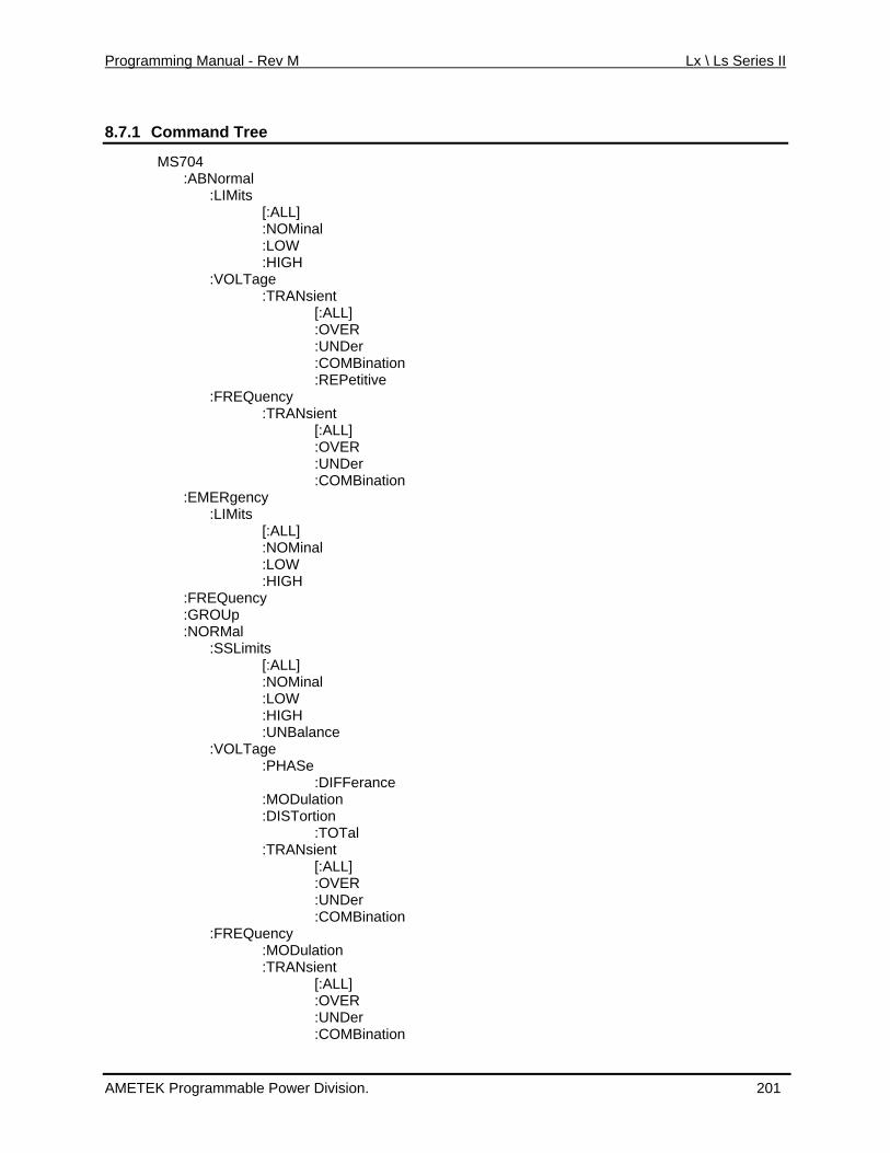
Programming Manual - Rev M Lx \ Ls Series II
8.7.1 Command Tree
MS704 :ABNormal :LIMits
IGH
age RANsient
[:ALL] :OVER
:UNDer :COMBination :REPetitive
:TRANsient [:ALL] :OVER :UNDer :COMBination :EMERgency :LIMits [:ALL] :NOMinal :LOW :HIGH :FREQuency :GROUp :NORMal :SSLimits [:ALL] :NOMinal :LOW :HIGH :UNBalance :VOLTage :PHASe :DIFFerance :MODulation :DISTortion :TOTal :TRANsient [:ALL] :OVER :UNDer :COMBination :FREQuency :MODulation :TRANsient [:ALL] :OVER :UNDer :COMBination
[:ALL] :NOMinal :LOW :H :VOLT :T :FREQuency
AMETEK Programmable Power Division. 201
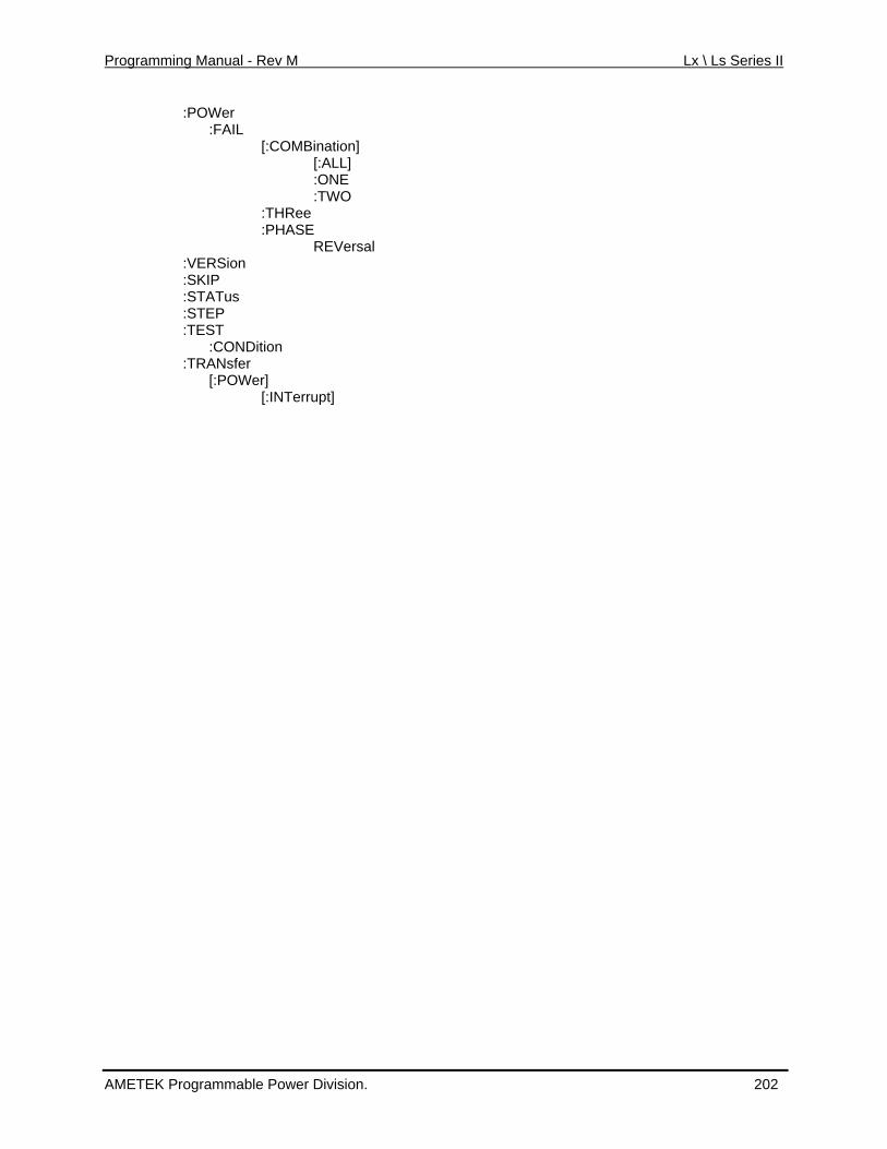
Programming Manual - Rev M Lx \ Ls Series II
:POWer
:VERSion :TEST :CONDition :TRANsfer [:POWer]
:FAIL [:COMBination] [:ALL] :ONE :TWO :THRee :PHASE REVersal
:SKIP :STATus :STEP
[:INTerrupt]
AMETEK Programmable Power Division. 202
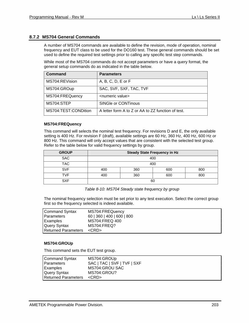
Programming Manual - Rev M Lx \ Ls Series II
8.7.2 MS704 General Commands
A number of MS704 commands are available to define the revision, mode of operation, nominal clas DO160 test. These general commands should be set
requi r to calling any specific test step commands.
rameters or have a query format, the ommand d in the table below.
frequency and EUT s to be used for thee the used to defin red test settings prio
While most of the MS704 commands do not accept pageneral setup c s do as indicate
Command Parameters
MS704:REVision A, B, C, D, E or F
MS704:GROup SAC, SVF, SXF, TAC, TVF
MS704:FREQuency <numeric value>
MS704:STEP SINGle or CONTinous
MS704:TEST:CONDition A letter form A to Z or AA to ZZ function of test.
y
y. For revisions D and E, the only available tings are 60 Hz, 360 Hz, 400 Hz, 600 Hz or
mmand y accept values that are consistent with the selected test group. efer to the table below for valid frequency settings by group.
MS704:FREQuenc
This command will selects the nominal test frequencz. For rev F (draft), available setsetting is 400 H ision
800 Hz. This co will onlR
GROUP Steady State Frequency in Hz SAC 400 TAC 400 SVF 400 360 600 800 TVF 400 360 600 800 SXF 60
Table 8-10: MS704 Steady state frequency by group
s e set prior to any test execution. Select the correct group e ilable.
ommand Syntax MS704:FREQuency
The nominal frequency election requency s
must bfirst so the f lected is indeed ava
CParameters 60 | 360 | 400 | 600 | 800 Examples MS704:FREQ 400 Query Syntax MS704:FREQ? Returned Parameters <CRD>
MS704:GROUp
This command sets the EUT test group.
Command S MS704:GROUp yntax Parameters SAC | TAC | SVF | TVF | SXF Examples MS704:GROU SAC Query Syntax MS704:GROU? Returned Parameters <CRD>
AMETEK Programmable Power Division. 203
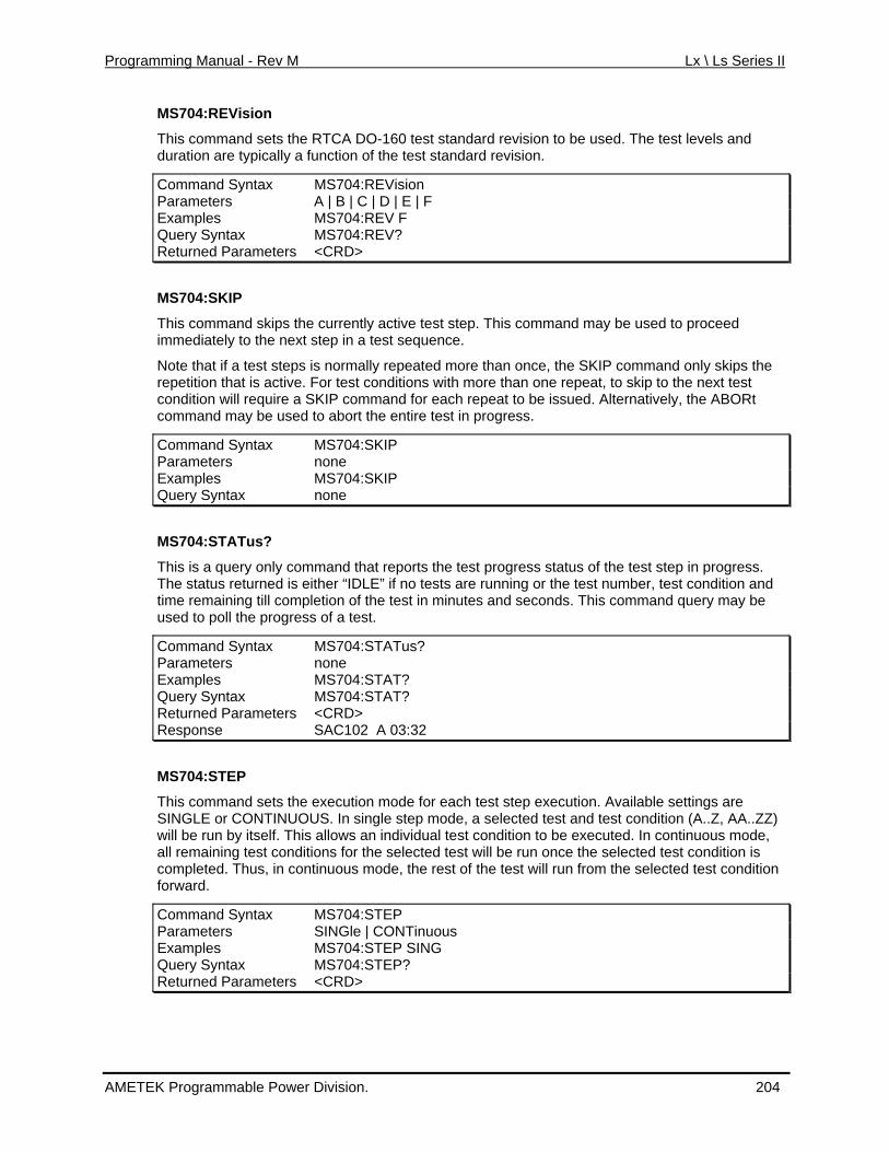
Programming Manual - Rev M Lx \ Ls Series II
MS704:REVision
This command sets the RTCA DO-160 test standard revision to be used. The test levels and duration are typically a function of the test standard revision.
Command Syntax MS704:REVision Parameters A | B | C | D | E | F Examples MS704:REV F Query Syntax MS704:REV? Returned Paramete <CRD> rs
MS704:SKIP
This command skips th currentlymediately to the nex tep in a
et s test sequence.
Note that if a test steps is normally repeated more than once, the SKIP command only skips the repetition that is active. For test conditions with more than one repeat, to skip to the next test condition will require a SKIP command for each repeat to be issued. Alternatively, the ABORt command may be used to abort the entire test in progress.
Command Syntax MS704:SKIP
active test step. This command may be used to proceed im
Parameters none Examples MS704:SKIP Query Syntax none
MS704:STATus?
This is a query only command that reports the test progress status of the test step in progress. The status returned is either “IDLE” if no tests are running or the test number, test condition and time remaining till completion of the test in minutes and seconds. This command query may be used to poll the progress of a test.
Command Syntax MS704:STATus? Parameters none Examples MS704:STAT? Query Syntax MS704:STAT? Returned Parameters <CRD> Response SAC102 A 03:32
MS704:STEP
This command sets the execution mode for each test step execution. Available settings are SINGLE or CONTINUOUS. In single step mode, a selected test and test condition (A..Z, AA..ZZ) will be run by itself. This allows an individual test condition to be executed. In continuous mode, all remaining test conditions for the selected test will be run once the selected test condition is completed. Thus, in continuous mode, the rest of the test will run from the selected test condition forward.
Command Syntax MS704:STEP Parameters SINGle | CONTinuous Examples MS704:STEP SING Query Syntax MS704:STEP? Returned Parameters <CRD>
AMETEK Programmable Power Division. 204
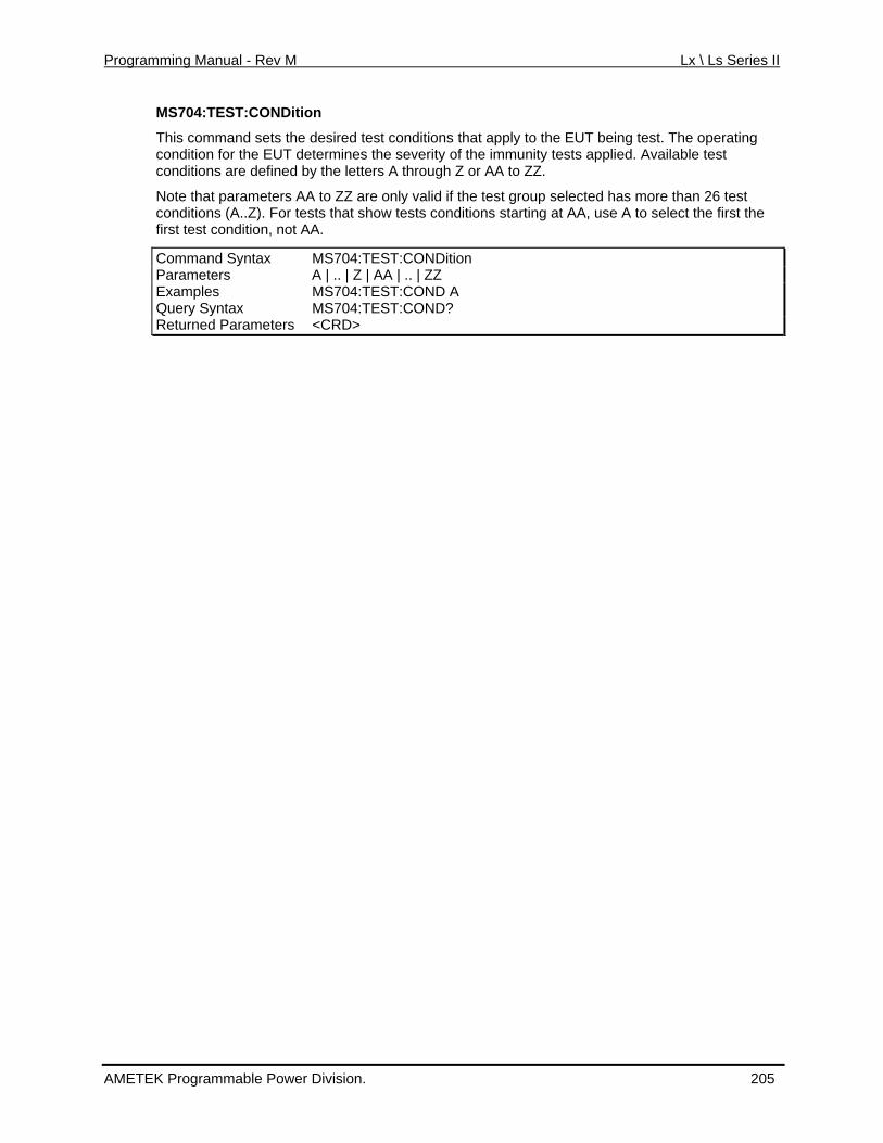
Programming Manual - Rev M Lx \ Ls Series II
MS704:TEST:CONDition
nditions that apply to the EUT being test. The operating
only valid if the test group selected has more than 26 test w tests conditions starting at AA, use A to select the first the
This command sets the desired test cocondition for the EUT determines the severity of the immunity tests applied. Available test conditions are defined by the letters A through Z or AA to ZZ.
Note that parameters AA to ZZ are conditions (A..Z). For tests that shofirst test condition, not AA.
Command Syntax MS704:TEST:CONDition Parameters A | .. | Z | AA | .. | ZZ Examples MS704:TEST:COND A Query Syntax MS704:TEST:COND? Returned Parameters <CRD>
AMETEK Programmable Power Division. 205
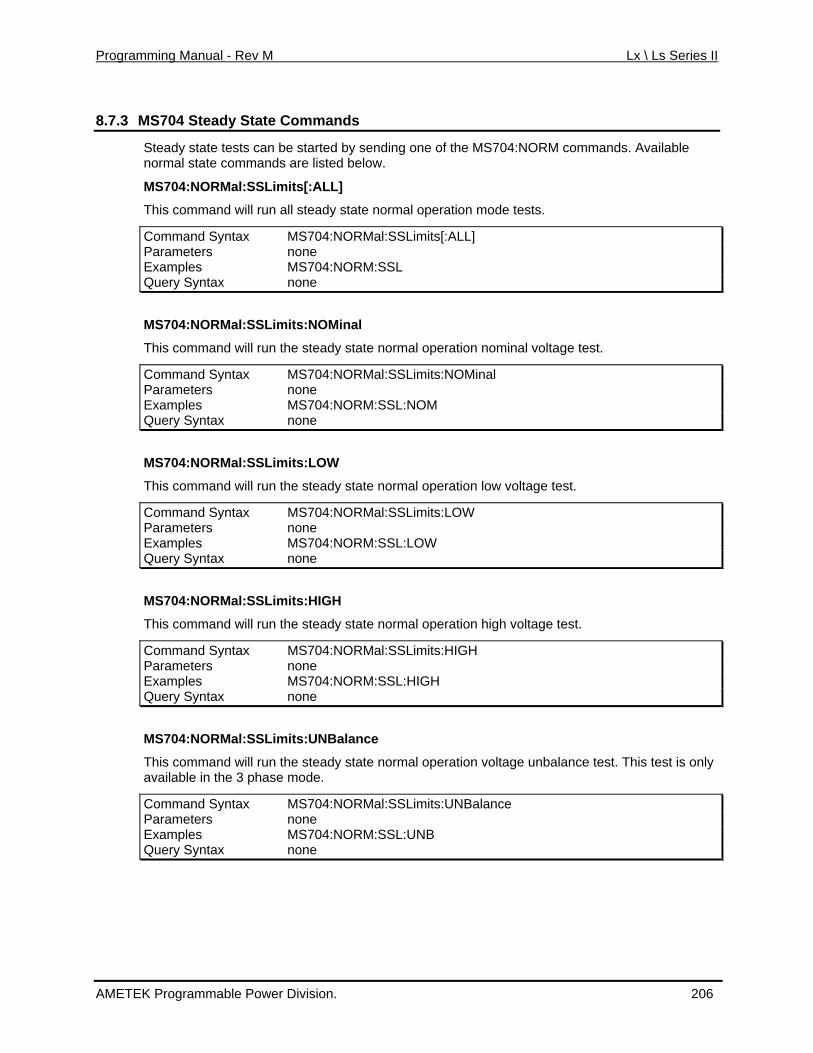
Programming Manual - Rev M Lx \ Ls Series II
8.7.3 MS704 Steady State Commands
Steady state tests can be started by sending one of the MS704:NORM commands. Available
ommand Syntax MS704:NORMal:SSLimits[:ALL]
normal state commands are listed below.
MS704:NORMal:SSLimits[:ALL]
This command ll stead will run a y state normal operation mode tests.
CParameters none Examples MS704:NORM:SSL Query Syntax none
MS704:NORMal:SSLimits:NOMinal
This command he stea will run t dy state normal operation nominal voltage test.
Command Syntax MS704:NORMal:SSLimits:NOMinal Parameters none Examples MS704:NORM:SSL:NOM Query Syntax none
MS704:NORMal:SSLimits:LOW
This command he stea will run t dy state normal operation low voltage test.
ommand Syntax MS704:NORMal:SSLimits:LOW CParameters none Examples MS704:NORM:SSL:LOW Query Syntax none
MS704:NORMal:SSLimits:HIGH
This command he stea will run t dy state normal operation high voltage test.
Command Syntax MS704:NORMal:SSLimits:HIGH Parameters none Examples MS704:NORM:SSL:HIGH Query Syntax none
MS704:NORMal:SSLimits:UNBalance
This command he steavailable in the mode
will run t dy state normal operation voltage unbalance test. This test is only a 3 phase .
Command Syntax MS704:NORMal:SSLimits:UNBalance Parameters none Examples MS704:NORM:SSL:UNB Query Syntax none
AMETEK Programmable Power Division. 206
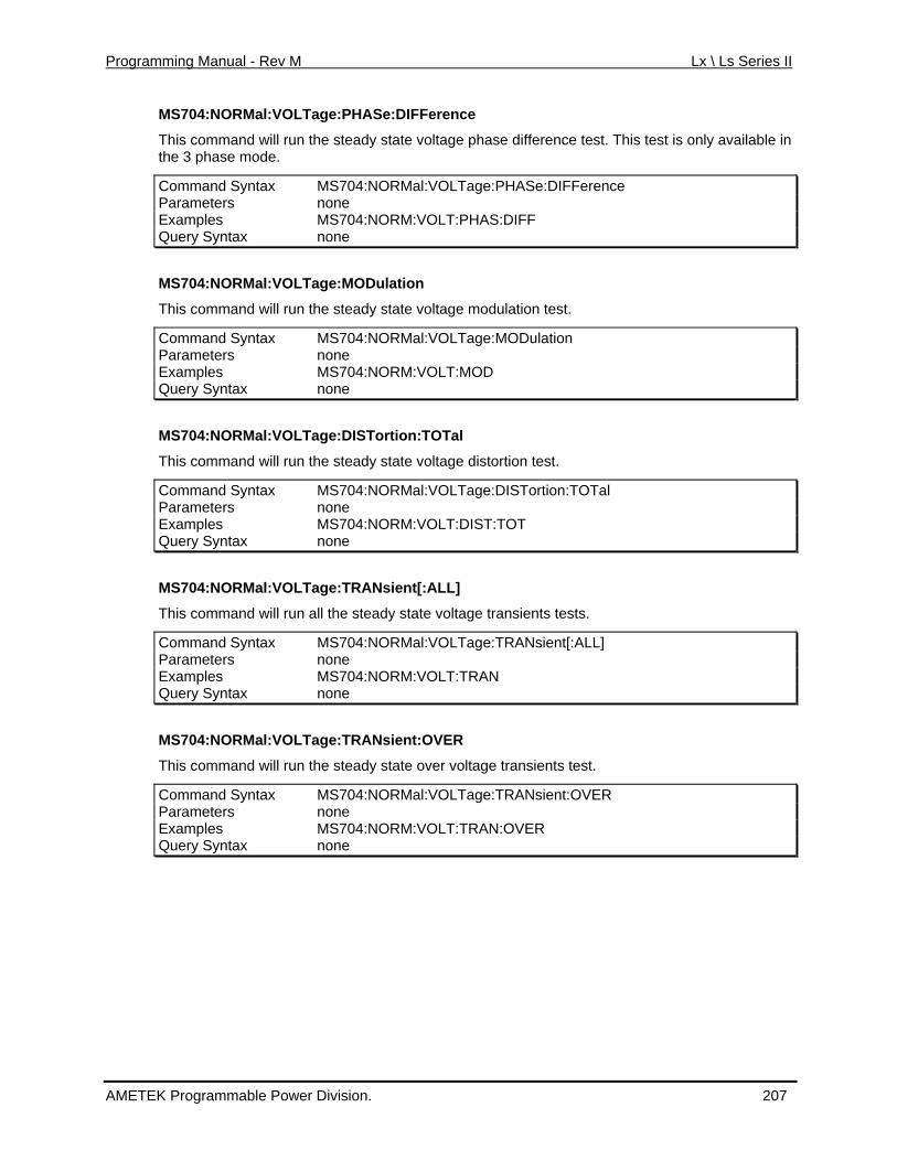
Programming Manual - Rev M Lx \ Ls Series II
MS704:NORMal:VOLTage:PHASe:DIFFerence
This test is only available in
OLTage:PHASe:DIFFerence
This command will run the steady state voltage phase difference test. the 3 phase mode.
Command Syntax MS704:NORMal:VParameters none Examples MS704:NORM:VOLT:PHAS:DIFF Query Syntax none
MS704:NORMal:VOLTage:MODulation
This command will run the steady state voltage modulation test.
Command Syntax MS704:NORMal:VOLTage:MODulation Parameters none Examples MS704:NORM:VOLT:MOD Query Syntax none
MS704:NORMal:VOLTage:DISTortion:TOTal
This command will run the steady state voltage distortion test.
Command Syntax MS704:NORMal:VOLTage:DISTortion:TOTal Parameters none Examples MS704:NORM:VOLT:DIST:TOT Query Syntax none
MS704:NORMal:VOLTage:TRANsient[:ALL]
This command will run all the steady state voltage transients tests.
Command Syntax MS704:NORMal:VOLTage:TRANsient[:ALL] Parameters none Examples MS704:NORM:VOLT:TRAN Query Syntax none
MS704:NORMal:VOLTage:TRANsient:OVER
This command will run the steady state over voltage transients test.
Command Syntax MS704:NORMal:VOLTage:TRANsient:OVER Parameters none Examples MS704:NORM:VOLT:TRAN:OVER Query Syntax none
AMETEK Programmable Power Division. 207
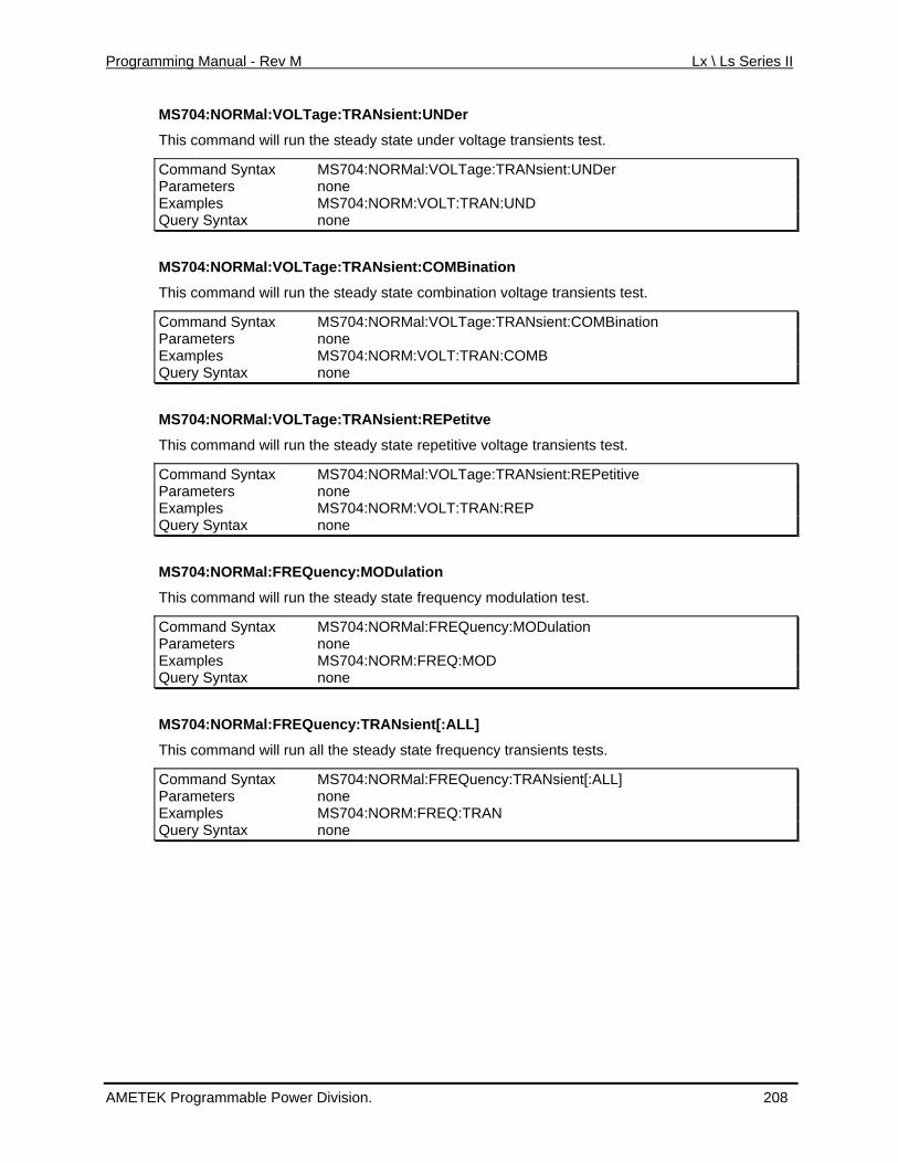
Programming Manual - Rev M Lx \ Ls Series II
MS704:NORMal:VOLTage:TRANsient:UNDer
This command will run the steady state under voltage transients test.
Command Syntax MS704:NORMal:VOLTage:TRANsient:UNDer Parameters none Examples MS704:NORM:VOLT:TRAN:UND Query Syntax none
MS704:NORMal:VOLTage:TRANsient:COMBination
st.
n
This command will run the steady state combination voltage transients te
Command Syntax MS704:NORMal:VOLTage:TRANsient:COMBinatioParameters none Examples MS704:NORM:VOLT:TRAN:COMB Query Syntax none
MS704:NORMal:VOLTage:TRANsient:REPetitve
This command will run the steady state repetitive voltage transients test.
Command Syntax MS704:NORMal:VOLTage:TRANsient:REPetitive Parameters none Examples MS704:NORM:VOLT:TRAN:REP Query Syntax none
MS704:NORMal:FREQuency:MODulation
This command will run the steady state frequency modulation test.
Command Syntax MS704:NORMal:FREQuency:MODulation Parameters none Examples MS704:NORM:FREQ:MOD Query Syntax none
MS704:NORMal:FREQuency:TRANsient[:ALL]
This command will run all the steady state frequency transients tests.
Command Syntax MS704:NORMal:FREQuency:TRANsient[:ALL] Parameters none Examples MS704:NORM:FREQ:TRAN Query Syntax none
AMETEK Programmable Power Division. 208
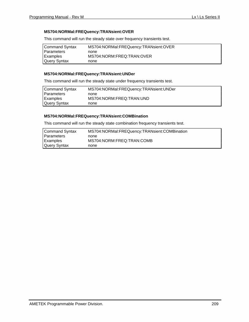
Programming Manual - Rev M Lx \ Ls Series II
MS704:NORMal:FREQuency:TRANsient:OVER
er frequency transients test. This command will run the steady state ov
Command Syntax MS704:NORMal:FREQuency:TRANsient:OVER Parameters none Examples MS704:NORM:FREQ:TRAN:OVER Query Syntax none
MS704:NORMal:FREQuency:TRANsient:UNDer
This command will run the steady state under frequency transients test.
tax :NORMal:FREQuency:TRANsient:UNDer Command Syn MS704Parameters none Examples MS704:NORM:FREQ:TRAN:UND Query Syntax none
MS704:NORMal:FREQuency:TRANsient:COMBination
This command will run the steady state combination frequency transients test.
tax Quency:TRANsient:COMBination Command Syn MS704:NORMal:FREParameters none Examples MS704:NORM:FREQ:TRAN:COMB Query Syntax none
AMETEK Programmable Power Division. 209
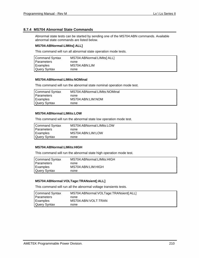
Programming Manual - Rev M Lx \ Ls Series II
8.7.4 MS704 Abnormal State Commands
Abnormal state tests can be started by sending one of the MS704:ABN co.
mmands. Available
will run a rmal state operation mode tests.
LL]
abnormal state commands are listed below
MS704:ABNormal:LIMits[:ALL]
This command ll abno
Command Syntax MS704:ABNormal:LIMits[:AParameters none Examples MS704:ABN:LIM Query Syntax none
MS704:ABNormal:LIMits:NOMinal
This command e abn will run th ormal state nominal operation mode test.
l Command Syntax MS704:ABNormal:LIMits:NOMinaParameters none Examples MS704:ABN:LIM:NOM Query Syntax none
MS704:ABNormal:LIMits:LOW
This command e abn will run th ormal state low operation mode test.
W Command Syntax MS704:ABNormal:LIMits:LOParameters none Examples MS704:ABN:LIM:LOW Query Syntax none
MS704:ABNormal:LIMits:HIGH
This command e abn will run th ormal state high operation mode test.
H Command Syntax MS704:ABNormal:LIMits:HIGParameters none Examples MS704:ABN:LIM:HIGH Query Syntax none
MS704:ABNormal:VOLTage:TRANsient[:ALL]
This command ll the a will run a bnormal voltage transients tests.
Command Syntax MS704:ABNormal:VOLTage:TRANsient[:ALL] Parameters none Examples MS704:ABN:VOLT:TRAN Query Syntax none
AMETEK Programmable Power Division. 210
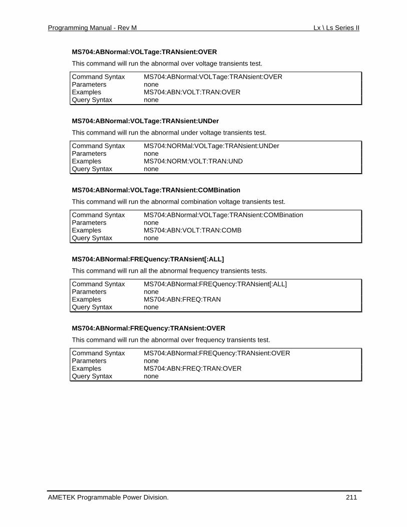
Programming Manual - Rev M Lx \ Ls Series II
MS704:ABNormal:VOLTage:TRANsient:OVER
This command will run the abnormal over voltage transients test.
Command Syntax MS704:ABNormal:VOLTage:TRANsient:OVER Parameters none Examples MS704:ABN:VOLT:TRAN:OVER Query Syntax none
MS704:ABNormal:VOLTage:TRANsient:UNDer
This command will run the abnormal under voltage transients test.
Command Syntax MS704:NORMal:VOLTage:TRANsient:UNDer Parameters none Examples MS704:NORM:VOLT:TRAN:UND Query Syntax none
MS704:ABNormal:VOLTage:TRANsient:COMBination
This command will run the abnormal combination voltage transients test.
Command Syntax MS704:ABNormal:VOLTage:TRANsient:COMBination Parameters none Examples MS704:ABN:VOLT:TRAN:COMB Query Syntax none
MS704:ABNormal:FREQuency:TRANsient[:ALL]
This command will run all the abnormal frequency transients tests.
Command Syntax MS704:ABNormal:FREQuency:TRANsient[:ALL] Parameters none Examples MS704:ABN:FREQ:TRAN Query Syntax none
MS704:ABNormal:FREQuency:TRANsient:OVER
This command will run the abnormal over frequency transients test.
Command Syntax MS704:ABNormal:FREQuency:TRANsient:OVER Parameters none Examples MS704:ABN:FREQ:TRAN:OVER Query Syntax none
AMETEK Programmable Power Division. 211
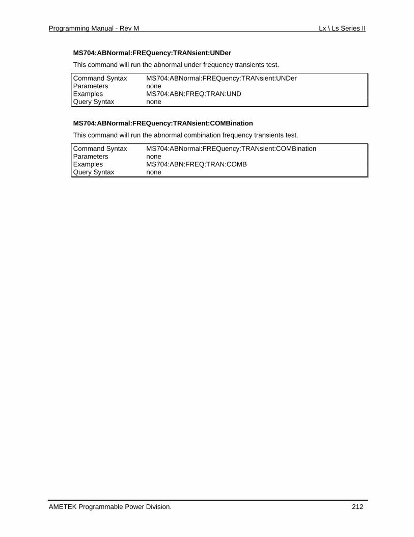
Programming Manual - Rev M Lx \ Ls Series II
MS704:ABNormal:FREQuency:TRANsient:UNDer
frequency transients test. This command will run the abnormal under
Command Syntax MS704:ABNormal:FREQuency:TRANsient:UNDer Parameters none Examples MS704:ABN:FREQ:TRAN:UND Query Syntax none
MS704:ABNormal:FREQuency:TRANsient:COMBination
y transients test.
tax :ABNormal:FREQuency:TRANsient:COMBination
This command will run the abnormal combination frequenc
Command Syn MS704Parameters none Examples MS704:ABN:FREQ:TRAN:COMB Query Syntax none
AMETEK Programmable Power Division. 212
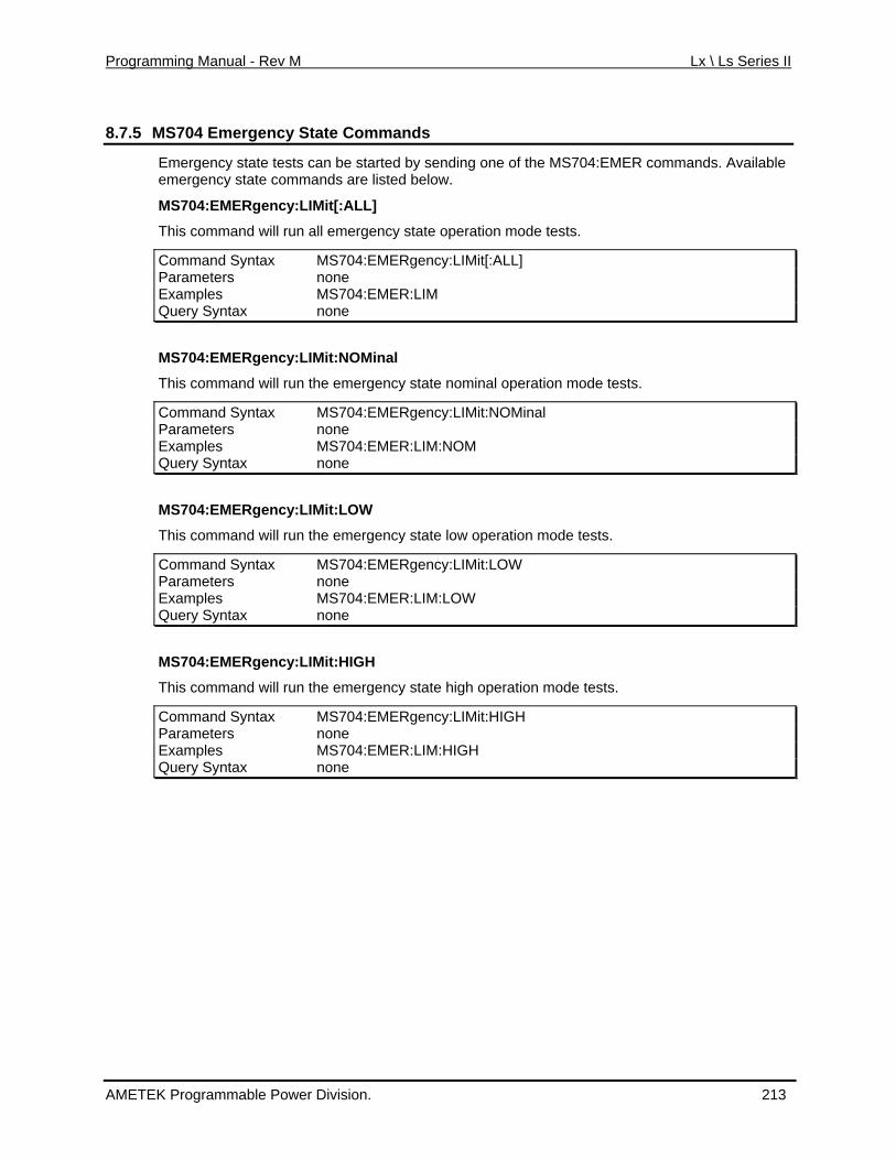
Programming Manual - Rev M Lx \ Ls Series II
8.7.5 MS704 Emergency State Commands
Emergency state tests can be started by sending one of the MS704:EMER commands. Avaemergency state commands are listed below.
ilable
MS704:EMERgency:LIMit[:ALL]
This command will run all emergency state operation mode tests.
Command Syntax MS704:EMERgency:LIMit[:ALL] Parameters none Examples MS704:EMER:LIM Query Syntax none
MS704:EMERgency:LIMit:NOMinal
This command will run the emergency state nominal operation mode tests.
Command Syntax MS704:EMERgency:LIMit:NOMinal Parameters none Examples MS704:EMER:LIM:NOM Query Syntax none
MS704:EMERgency:LIMit:LOW
This command will run the emergency state low operation mode tests.
Command Syntax MS704:EMERgency:LIMit:LOW Parameters none Examples MS704:EMER:LIM:LOW Query Syntax none
MS704:EMERgency:LIMit:HIGH
H
This command will run the emergency state high operation mode tests.
Command Syntax MS704:EMERgency:LIMit:HIGParameters none Examples MS704:EMER:LIM:HIGH Query Syntax none
AMETEK Programmable Power Division. 213
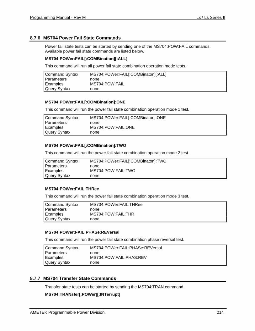
Programming Manual - Rev M Lx \ Ls Series II
8.7.6 MS704 Power Fail State Commands
Power fail state tests can be started by sending one of the MS704:POW:FAIL commands.
r:FAIL[:C nation][:ALL]
This command will run all power fail state combination operation mode tests.
Command Syntax MS704:POWer:FAIL[:COMBinaton][:ALL]
Available power fail state commands are listed below.
MS704:POWe OMBi
Parameters none Examples MS704:POW:FAIL Query Syntax none
MS704:POWer:FAIL[:COMBination]:ONE
This command will run the power fail state combination operation mode 1 test.
Command Syntax MS704:POWer:FAIL[:COMBinaton]:ONE Parameters none Examples MS704:POW:FAIL:ONE Query Syntax none
MS704:POWer:FAIL[:COMBination]:TWO
This command will run the power fail state combination operation mode 2 test.
Command Syntax MS704:POWer:FAIL[:COMBinaton]:TWO Parameters none Examples MS704:POW:FAIL:TWO Query Syntax none
MS704:POWer:FAIL:THRee
This command will run the power fail state combination operation mode 3 test.
Command Syntax MS704:POWer:FAIL:THRee Parameters none Examples MS704:POW:FAIL:THR Query Syntax none
MS704:POWer:FAIL:PHASe:REVersal
This command will run the power fail state combination phase reversal test.
Command Syntax MS704:POWer:FAIL:PHASe:REVersal Parameters none Examples MS704:POW:FAIL:PHAS:REV Query Syntax none
8.7.7 MS704 Transfer State Commands
Transfer state tests can be started by sending the MS704:TRAN command.
MS704:TRANsfer[:POWer][:INTerrupt]
AMETEK Programmable Power Division. 214
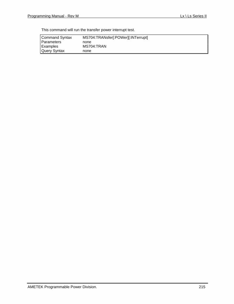
Programming Manual - Rev M Lx \ Ls Series II
This command will run the transfer power interrupt test.
:INTerrupt] Command Syntax MS704:TRANsfer[:POWer][Parameters none Examples MS704:TRAN Query Syntax none
AMETEK Programmable Power Division. 215
Programming Manual - Rev M Lx \ Ls Series II
8.8 Airbus ABD0100.1.8 Test Option (-ABD)
The -ABD option is implemented through the LxGui Windows software provided with each AC urce. As such, there are no SCPI comm D option. Refer to the
Software User Manual (CI P/N 4994-97
8.9 rbus A350, ABD0100.1.8.1 Test Opti
power soionics
ands that ap ly to the –ABpAv 1) for more information.
Ai on (-A350)
The –Awer
350 option is implemented through the Lx ided with each AC source. As such, there are no SCPI comm 50 option. Refer to
nics Software User Manual (CI P/N 4994 on.
8.1 AMD24 Test Option (-AMD)
Gui Windows software provA3po ands that apply to the –
the Avio -971) for more informati
0 Airbus
The -AMD option is implemented through the Lxwer source. As such, there are no SCPI comm at apply to the –AMD option. Refer to the
vionics Software User Manual (CI P/N 4994-971) fo .
oeing 787B3-0147 Test Option (-B787)
Gui Windows software provided with each AC po ands thA r more information
8.11 B
The –B787 option is implemented through the LxGui Windows software provided with each AC such, there are no SCPI comm –B787 option. Refer to
ics Software User Manual (CI P/N 4994-97 tion. power source. As ands that apply to the
rmathe Avion 1) for more info
AMETEK Programmable Power Division. 216
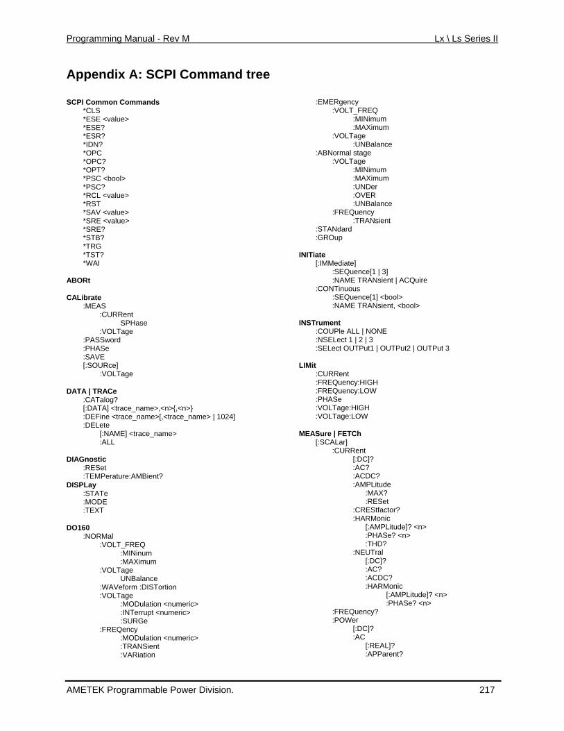
Programming Manual - Rev M Lx \ Ls Series II
Appendix A: SCPI Command tree SCPI Common Commands
*CLS *ESE <valu*ESE? *ESR? *IDN? *OPC
*PSC*PSC? *RCL <value> *RST *SAV <valu*SRE <value> *SRE? *STB? *TRG *TST*WA
ABORt CALibrate
SPHase e
,<n>} ,<trace_name> | 1024]
?
m
tion :VOLTage
:MODulation <numeric> errupt <numeric>
CQuire
l>
ut2 | OUTPut 3
e
or?
Tral
DC? :HARMonic
[:AMPLitude]? <n> :PHASe? <n>
:APParent?
e>
*OPC? *OPT?
<bool>
e>
? I
:MEAS :CURRent
:VOLTag:PASSword :PHASe :SAVE [:SOURce]
:VOLTage DATA | TRACe
:CATalog? <n>{[:DATA] <trace_name>,
:DEFine <trace_name>[:DELete
ce_name>[:NAME] <tra:ALL
DIAGnostic :RESet :TEMPerature:AMBient
DISPLay :STATe :MODE :TEXT
DO160 :NORMal :VOLT_FREQ :MINinu :MAXimum :VOLTage UNBalance :WAVeform :DISTor :INT :SURGe :FREQency :MODulation <numeric>
nt :TRANSie :VARiation
:EMERgency :VOLT_FREQ :MINimum :MAXimum :VOLTage :UNBalance :ABNormal stage :VOLTage :MINimum :MAXimum :UNDer :OVER :UNBalance :FREQuency :TRANsient :STANdard :GROup INITiate
[:IMMediate] :SEQuence[1 | 3] :NAME TRANsient | A
:CONTinuous :SEQuence[1] <boo:NAME TRANsient, <bool>
INSTrument :COUPle ALL | NONE:NSELect 1 | 2 | 3
UTP:SELect OUTPut1 | O
LIMit :CURRent :FREQuency:HIGH :FREQuency:LOW :PHASe :VOLTage:HIGH :VOLTage:LOW
MEASure | FETCh
[:SCALar] :CURRent
[:DC]? :AC?
C?:ACD:AMPLitud
:MAX? t :RESe
:CREStfact:HARMonic
[:AMPLitude]? <n> :PHASe? <n> :THD?
:NEU[:DC]?
? :AC:AC
:FREQuency? :POWer
[:DC]? :AC
[:REAL]?
AMETEK Programmable Power Division. 217
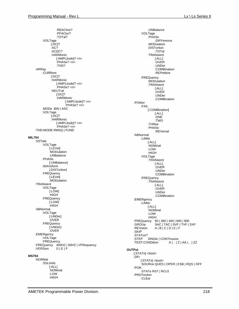
Programming Manual - Rev L Lx \ Ls Series II
:REACtive? :PFACtor?
Tage
:HARMonic [:AMPLitude]? <n> :PHASe? <n>
:CURRent
:HARMonic [:AMPLitude]? <n>
e? <n> :NE
[:DC]? :HARMonic
PLitude]? <n> :PHASe? <n>
ODe BIN | ASC LTage
[:DC]? RMonic
de]? <n>
:THD:MODE RMSQ | FUND MIL704 :MODulation :UNB :PHASe [:UN [:DISTortion] :FREQuency [:LE :MODulation :TRANsient :VOLTage [:LO :HIG :FREQuency :ABNormal [:UN :FREQ [:UN : :EMERgency :FREQuency HZ | VFRequency :VER MS704 :NO :SSLimits [ :NO : :HIG
:UNBalance :DIFFerence :MODulation
al [ L] : ER :UNDer :COMBination :MODulation :TRANsient :POWer [:COMBination] : :THR :PHA
[ l :HIGH :TRANsient [:ALL] : VER :UNDer :COMBination :TRANsient :COMBination :EMERgency
:LOW
0 | 360 | 400 | 600 | 800 :GR SVF | TVF | SXF :REV | E | F :SKI :STATus? :STEP SINGle | CONTinuous :TEST:CONDi A | .. | Z | AA | .. | ZZ OUTPut
[:STATe] <boo:DFI
[:STATe] OPER | ESB | RQS | OFF
L0 ion ar
:TOTal? :VOL
[:DC]? :AC? :ACDC?
:THD? :ARRay
[:DC]?
:PHASUTral
[:AM
:M:VO
:HA[:AMPLitu:PHASe? <n>
:SSTate :VOLTage
[:LEVel]
alance
Balance] :WAVeform
Vel]
W] H
[:LOW] :HIGH
:VOLTage Der]
:OVER uency
Der] OVER
:VOLTage :FREQuency
400HZ | 60Sion D | E | F
RMal
:ALL] Minal
LOW H
:VOLTage :PHASe
:DISTortion :TOT :TRANsient
:ALOV
:REPetitive :FREQuency
[:ALL] :OVER
:UNDer :COMBination
:FAIL
:ONE [:ALL]
TWO ee Se
:REVersal :ABNormal :LIMits
:ALL] :NOMina :LOW
:VOLTage
O
:FREQuency
[:ALL] :OVER :UNDer
:LIMits [:ALL]
:NOMinal
:HIGH:FREQuency 6
OUp SAC | TAC |A | B | C | Dision
P
tion
l>
<bool> :SOURce
:PON QUES |
:STATe RST | RC
:PROTect:CLE
AMETEK Programmable Power Division. 218
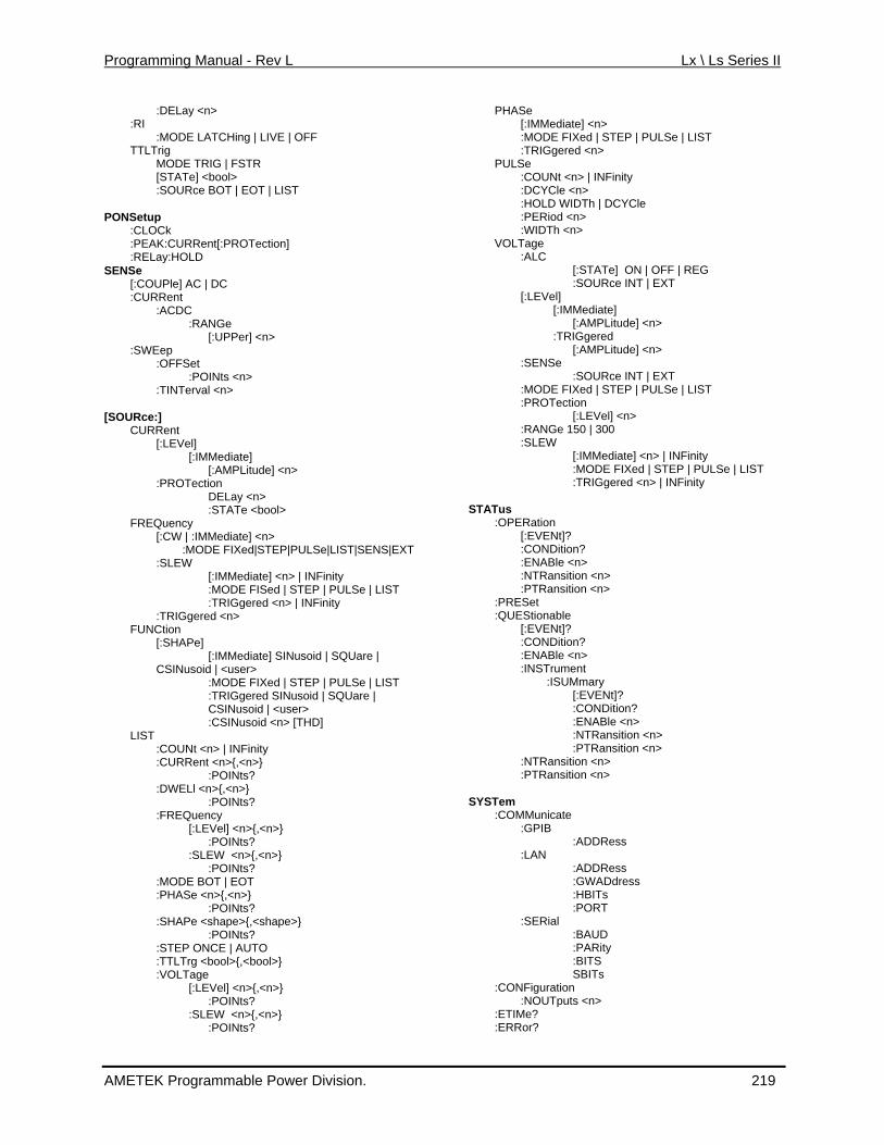
Programming Manual - Rev L Lx \ Ls Series II
:DELay <n> :RI
:MODE LATCHing | LIVE | OFF
TRIG | FSTR [STATe] <bool> :SOURce BOT | EOT | LIST
PONSetu:CLO:PEAK:CURRent[:PROTection]
SENSe [:COUPle] AC | DC
[:UPPer] <n> :SW
al <n>
[SOURce:] CURRent
[:LEVel] [:IMMediate]
[:AMPLitude] <n> :PROTection
DELay <n> :STATe <bool>
FREQuency [:CW | :IMMediate] <n>
:MODE FIXed|STEP|PULSe|LIST|SENS|EXT :SLEW
[:IMMediate] <n> | INFinity :MODE FISed | STEP | PULSe | LIST :TRIGgered <n> | INFinity
:TRIGgered <n> FUNCtion
[:SHAPe] [:IMMediate] SINusoid | SQUare |
CSINusoid | <user> :MODE FIXed | STEP | PULSe | LIST :TRIGgered SINusoid | SQUare | CSINusoid | <user> :CSINusoid <n> [THD]
LIST :COUNt <n> | INFinity :CURRent <n>{,<n>}
:POINts? :DWELl <n>{,<n>}
:POINts? :FREQuency
[:LEVel] <n>{,<n>} :POINts?
:SLEW <n>{,<n>} :POINts?
:MODE BOT | EOT :PHASe <n>{,<n>}
:POINts? :SHAPe <shape>{,<shape>}
:POINts? :STEP ONCE | AUTO :TTLTrg <bool>{,<bool>} :VOLTage
[:LEVel] <n>{,<n>} :POINts?
:SLEW <n>{,<n>} :POINts?
PHASe [:IMMediate] <n> :MODE FIXed | STEP | PULSe | LIST :TRIGgered <n>
PULSe :COUNt <n> | INFinity :DCYCle <n> :HOLD WIDTh | DCYCle :PERiod <n> :WIDTh <n>
VOLTage :ALC
[:STATe] ON | OFF | REG :SOURce INT | EXT
[:LEVel] [:IMMediate]
[:AMPLitude] <n> :TRIGgered
[:AMPLitude] <n> :SENSe
:SOURce INT | EXT :MODE FIXed | STEP | PULSe | LIST :PROTection
[:LEVel] <n> :RANGe 150 | 300 :SLEW
[:IMMediate] <n> | INFinity :MODE FIXed | STEP | PULSe | LIST :TRIGgered <n> | INFinity
STATus
:OPERation [:EVENt]? :CONDition? :ENABle <n> :NTRansition <n> :PTRansition <n>
:PRESet :QUEStionable
[:EVENt]? :CONDition? :ENABle <n> :INSTrument
:ISUMmary [:EVENt]? :CONDition? :ENABle <n> :NTRansition <n> :PTRansition <n>
:NTRansition <n> :PTRansition <n>
SYSTem
:COMMunicate :GPIB
:ADDRess :LAN
:ADDRess :GWADdress :HBITs :PORT
:SERial :BAUD :PARity :BITS SBITs
:CONFiguration :NOUTputs <n>
:ETIMe? :ERRor?
TTLTrig MODE
p Ck
:RELay:HOLD
:CURRent :ACDC
:RANGe
Eep :OFFSet
:POINts <n> :TINTerv
AMETEK Programmable Power Division. 219

Programming Manual - Rev L Lx \ Ls Series II
:LANGuage SCPI | APEN :REMote :RW:TEM:VER
TRIGger
[:IMMediate] URce BUS | EXTernal | IMMediate
Lay <n> ronize | :SEQuence2
Mediate
ediate] Rce BUS | EXTernal | IMMediate
LOCK Perature? Sion?
[:TRANsient | SEQuence1]
:SODE
:SYNCh:SOURce PHASe | IM:PHASe <n>
| :SEQuence3 :ACQuire [:IMM:SOU
:SEQuence1 :DEFine TRANsient
:SEQuence2 :DEFine SYNChronize
:SEQuence3 :DEFine ACQuire
AMETEK Programmable Power Division. 220
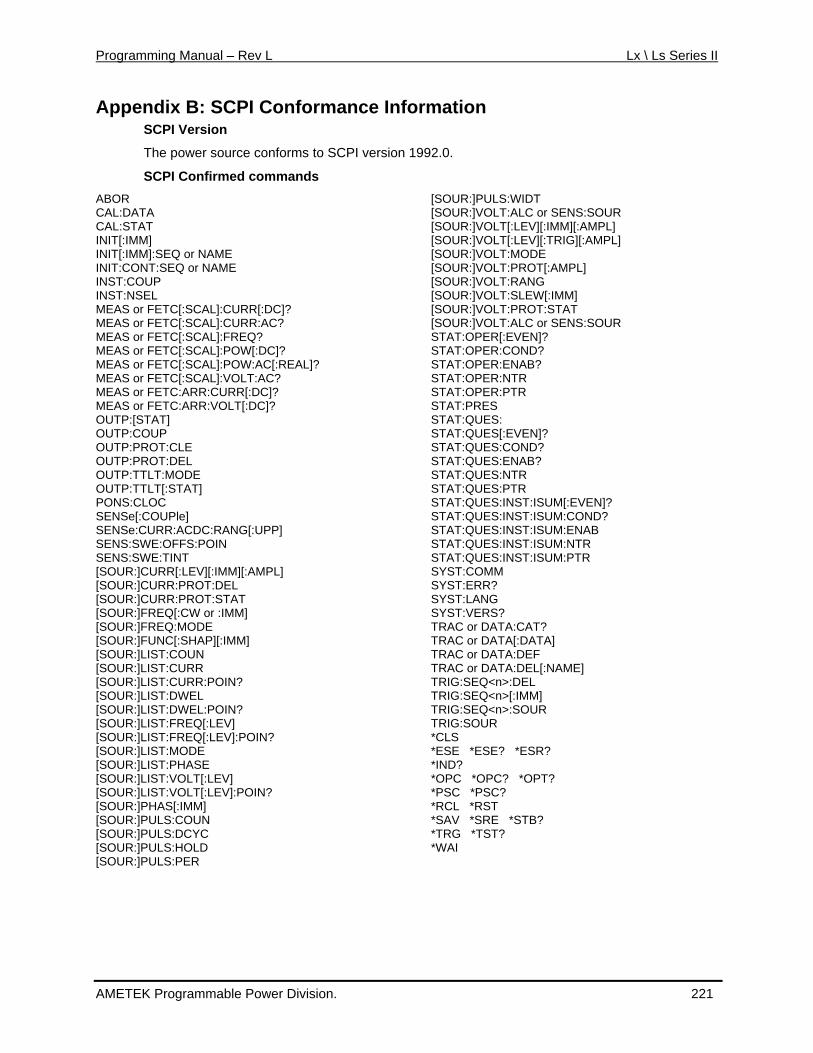
Programming Manual – Rev L Lx \ Ls Series II
Appendix B: SCPI Conformance Information
r source conforms to SCPI version 199
PI Confirmed commands
or NAME or NAME
URR[:DC]? URR:AC?
Q? OW[:DC]? OW:AC[:REAL]?
C[:SCAL]:VOLT:AC?
[:UPP]
[:AMPL] :PROT:DEL
R:PROT:STAT or :IMM]
DE C[:SHAP][:IMM]
N RR
E
:SOUR
EN]? ST:ISUM:COND? ST:ISUM:ENAB
R TR
SCPI Version
The powe 2.0.
SCABOR CAL:DATA CAL:STAT INIT[:IMM] INIT[:IMM]:SEQ INIT:CONT:SEQINST:COUP INST:NSEL MEAS or FETC[:SCAL]:CMEAS or FETC[:SCAL]:CMEAS or FETC[:SCAL]:FREMEAS or FETC[:SCAL]:PMEAS or FETC[:SCAL]:PMEAS or FETMEAS or FETC:ARR:CURR[:DC]? MEAS or FETC:ARR:VOLT[:DC]? OUTP:[STAT] OUTP:COUP OUTP:PROT:CLE OUTP:PROT:DEL OUTP:TTLT:MODE OUTP:TTLT[:STAT] PONS:CLOC SENSe[:COUPle] SENSe:CURR:ACDC:RANGSENS:SWE:OFFS:POIN SENS:SWE:TINT [SOUR:]CURR[:LEV][:IMM][SOUR:]CURR[SOUR:]CUR[SOUR:]FREQ[:CW[SOUR:]FREQ:MO[SOUR:]FUN[SOUR:]LIST:COU[SOUR:]LIST:CU[SOUR:]LIST:CURR:POIN? [SOUR:]LIST:DWEL [SOUR:]LIST:DWEL:POIN? [SOUR:]LIST:FREQ[:LEV] [SOUR:]LIST:FREQ[:LEV]:POIN? [SOUR:]LIST:MODE [SOUR:]LIST:PHASE [SOUR:]LIST:VOLT[:LEV] [SOUR:]LIST:VOLT[:LEV]:POIN? [SOUR:]PHAS[:IMM] [SOUR:]PULS:COUN [SOUR:]PULS:DCYC [SOUR:]PULS:HOLD [SOUR:]PULS:PER
[SOUR:]PULS:WIDT [SOUR:]VOLT:ALC or SENS:SOUR [SOUR:]VOLT[:LEV][:IMM][:AMPL] [SOUR:]VOLT[:LEV][:TRIG][:AMPL] [SOUR:]VOLT:MOD[SOUR:]VOLT:PROT[:AMPL] [SOUR:]VOLT:RANG [SOUR:]VOLT:SLEW[:IMM] [SOUR:]VOLT:PROT:STAT [SOUR:]VOLT:ALC or SENSSTAT:OPER[:EVEN]? STAT:OPER:COND? STAT:OPER:ENAB? STAT:OPER:NTR STAT:OPER:PTR STAT:PRES STAT:QUES: STAT:QUES[:EVEN]? STAT:QUES:COND? STAT:QUES:ENAB? STAT:QUES:NTR STAT:QUES:PTR STAT:QUES:INST:ISUM[:EVSTAT:QUES:INSTAT:QUES:INSTAT:QUES:INST:ISUM:NTSTAT:QUES:INST:ISUM:PSYST:COMM SYST:ERR? SYST:LANG SYST:VERS? TRAC or DATA:CAT? TRAC or DATA[:DATA] TRAC or DATA:DEF TRAC or DATA:DEL[:NAME] TRIG:SEQ<n>:DEL TRIG:SEQ<n>[:IMM] TRIG:SEQ<n>:SOUR TRIG:SOUR *CLS *ESE *ESE? *ESR? *IND? *OPC *OPC? *OPT? *PSC *PSC? *RCL *RST *SAV *SRE *STB? *TRG *TST? *WAI
AMETEK Programmable Power Division. 221
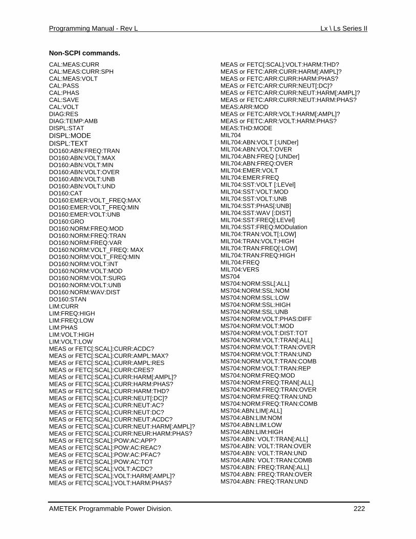
Programming Manual - Rev L Lx \ Ls Series II
Non-SCPI commands. CAL:MEAS:CURR
H
DISPL:MODE
EQ:TRAN LT:MAX
OLT:MIN LT:OVER LT:UNB
D
T_FREQ:MAX OLT_FREQ:MIN
LT:UNB
:FREQ:MOD
DO160:NORM:FREQ:VAR EQ: MAX
MIN DO160:NORM:VOLT:INT
IM:CURR
LIM:FREQ:LOW LIM:PHAS LIM:VOLT:HIGH LIM:VOLT:LOW MEAS or FETC[:SCAL]:CURR:ACDC? MEAS or FETC[:SCAL]:CURR:AMPL:MAX? MEAS or FETC[:SCAL]:CURR:AMPL:RES MEAS or FETC[:SCAL]:CURR:CRES? MEAS or FETC[:SCAL]:CURR:HARM[:AMPL]? MEAS or FETC[:SCAL]:CURR:HARM:PHAS? MEAS or FETC[:SCAL]:CURR:HARM:THD? MEAS or FETC[:SCAL]:CURR:NEUT[:DC]? MEAS or FETC[:SCAL]:CURR:NEUT:AC? MEAS or FETC[:SCAL]:CURR:NEUT:DC? MEAS or FETC[:SCAL]:CURR:NEUT:ACDC? MEAS or FETC[:SCAL]:CURR:NEUT:HARM[:AMPL]? MEAS or FETC[:SCAL]:CURR:NEUR:HARM:PHAS? MEAS or FETC[:SCAL]:POW:AC:APP? MEAS or FETC[:SCAL]:POW:AC:REAC? MEAS or FETC[:SCAL]:POW:AC:PFAC? MEAS or FETC[:SCAL]:POW:AC:TOT MEAS or FETC[:SCAL]:VOLT:ACDC? MEAS or FETC[:SCAL]:VOLT:HARM[:AMPL]? MEAS or FETC[:SCAL]:VOLT:HARM:PHAS?
HD? ARM[:AMPL]?
PHAS?
NEUT:HARM[:AMPL]? MEAS or FETC:ARR:CURR:NEUT:HARM:PHAS?
MEAS or FETC:ARR:VOLT:VOLT:HARM:PHAS?
MIL704:ABN:VOLT:OVER
MIL704:SST:PHAS[:UNB]
on
MIL704:TRAN:VOLT:HIGH :FREQ[:LOW] :FREQ:HIGH
Q S
SL:LOW
MS704:NORM:SSL:UNB MS704:NORM:VOLT:PHAS:DIFF MS704:NORM:VOLT:MOD MS704:NORM:VOLT:DIST:TOT MS704:NORM:VOLT:TRAN[:ALL] MS704:NORM:VOLT:TRAN:OVER MS704:NORM:VOLT:TRAN:UND MS704:NORM:VOLT:TRAN:COMB MS704:NORM:VOLT:TRAN:REP MS704:NORM:FREQ:MOD MS704:NORM:FREQ:TRAN[:ALL] MS704:NORM:FREQ:TRAN:OVER MS704:NORM:FREQ:TRAN:UND MS704:NORM:FREQ:TRAN:COMB MS704:ABN:LIM[:ALL] MS704:ABN:LIM:NOM MS704:ABN:LIM:LOW MS704:ABN:LIM:HIGH MS704:ABN: VOLT:TRAN[:ALL] MS704:ABN: VOLT:TRAN:OVER MS704:ABN: VOLT:TRAN:UND MS704:ABN: VOLT:TRAN:COMB MS704:ABN: FREQ:TRAN[:ALL] MS704:ABN: FREQ:TRAN:OVER MS704:ABN: FREQ:TRAN:UND
CAL:MEAS:CURR:SPCAL:MEAS:VOLT CAL:PASS CAL:PHAS CAL:SAVE CAL:VOLT DIAG:RES DIAG:TEMP:AMB DISPL:STAT
DISPL:TEXTDO160:ABN:FRDO160:ABN:VODO160:ABN:VDO160:ABN:VODO160:ABN:VODO160:ABN:VOLT:UNDO160:CAT DO160:EMER:VOLDO160:EMER:VDO160:EMER:VODO160:GRO DO160:NORMDO160:NORM:FREQ:TRAN
DO160:NORM:VOLT_FRDO160:NORM:VOLT_FREQ:
DO160:NORM:VOLT:MOD DO160:NORM:VOLT:SURG DO160:NORM:VOLT:UNB DO160:NORM:WAV:DIST DO160:STAN LLIM:FREQ:HIGH
MEAS or FETC[:SCAL]:VOLT:H
:HARM:TMEAS or FETC:ARR:CURRMEAS or FETC:ARR:CURR:HARM:
CURR:NEUT[:DC]? MEAS or FETC:ARR:MEAS or FETC:ARR:CURR:
MEAS:ARR:MOD :HARM[:AMPL]?
MEAS or FETC:ARRMEAS:THD:MODE MIL704 MIL704:ABN:VOLT [:UNDer]
MIL704:ABN:FREQ [:UNDer] ER MIL704:ABN:FREQ:OV
MIL704:EMER:VOLT MIL704:EMER:FREQ MIL704:SST:VOLT [:LEVel]MIL704:SST:VOLT:MOD MIL704:SST:VOLT:UNB
MIL704:SST:WAV [:DIST] MIL704:SST:FREQ[:LEVel]
tiMIL704:SST:FREQ:MODulaOLT[:LOW] MIL704:TRAN:V
MIL704:TRANNMIL704:TRA
MIL704:FREMIL704:VERMS704 MS704:NORM:SSL[:ALL]
L:NOM MS704:NORM:SSS704:NORM:SM
MS704:NORM:SSL:HIGH
AMETEK Programmable Power Division. 222
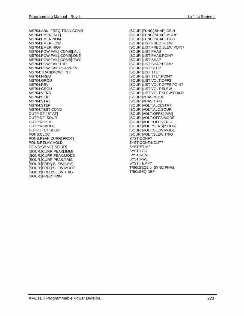
Programming Manual - Rev L Lx \ Ls Series II
MS704:ABN: FREQ:TRAN:COMB MS704:EMER[:ALL] MS704:EMS704:EMS704:EMER:HIGH MS704:PMS704:PMS704:POWMS704:POWMS704:POWMS704:TMS704:FMS704:GMS704:REV MS704:GROU MS704:VERS MS704:SKIP MS704:STAT MS704:STEP MS704:TEST:CONOUTP:DFI[:STAT] OUTP:DFI:SOUR OUTP:RI:LEV OUTP:RI:MODE OUTP:TTLT:SOUR PONS:CLOC PONS:PEAK:CURR[:PROT] PONS:RELAY:HOLD PONS:S[SOUR:][SOUR:][SOUR:]CURR:PEAK:T[SOUR:][SOUR:]FREQ:SLEW:MODE [SOUR:]FR :[SOUR:]FREQ
[SOUR:]FUNC[:SHAP]:CSIN [SOUR:]FUNC[:SHAP]:MODE
:FREQ:SLEW :FREQ:SLEW:POIN?
UR:]LIST:PHAS
[SOUR:]LIST:STEP
[SOUR:]LIST:VOLT:OFFS [SOUR:]LIST:VOLT:OFFS:POIN? [SOUR:]LIST:VOLT
:VOLT:SLEW:POIN? :]PHAS:MODE :]PHAS:TRIG :]VOLT:ALC[:STAT]
[SOUR:]VOLT:OFFS:TRIG OUR:]VOLT:SENS[:SOUR]
:SLEW:MODE RIG
SYST:CONF:NOUT?
TRIG:SEQ2 or SYNC:PHAS TRIG:SEQ:D
MER:NOM MER:LOW
[SOUR:]FUNC[:SHAP]:TRIG [SOUR:]LIST
OW:FAIL[:COMB][:ALL] [SOUR:]LIST[SO
OW:FAIL[:COMB]:ONE :FAIL[:COMB]:TWO :FAIL:THR :FAIL:PHAS:REV
[SOUR:]LIST:PHAS:POIN? [SOUR:]LIST:SHAP [SOUR:]LIST:SHAP:POIN?
RAN[:POW][:INT] REQ ROU
[SOUR:]LIST:TTLT [SOUR:]LIST:TTLT:POIN?
D
YNC[:SOUR] CURR:PEAK[:IMM] CURR:PEAK:MODE
SYST:ETIM? SYST:LOC SYST:REM
RIG FREQ:SLEW[:IMM}
SYST:RWL SYST:TEMP?
EQ:SLEW TRIG :TRIG
:SLEW[SOUR:]LIST[SOUR[SOUR[SOUR[SOUR:]VOLT:ALC:SOUR [SOUR:]VOLT:OFFS[:IMM] [SOUR:]VOLT:OFFS:MODE
[S[SOUR:]VOLT[SOUR:]VOLT:SLEW:TSYST:CONF?
EF
AMETEK Programmable Power Division. 223
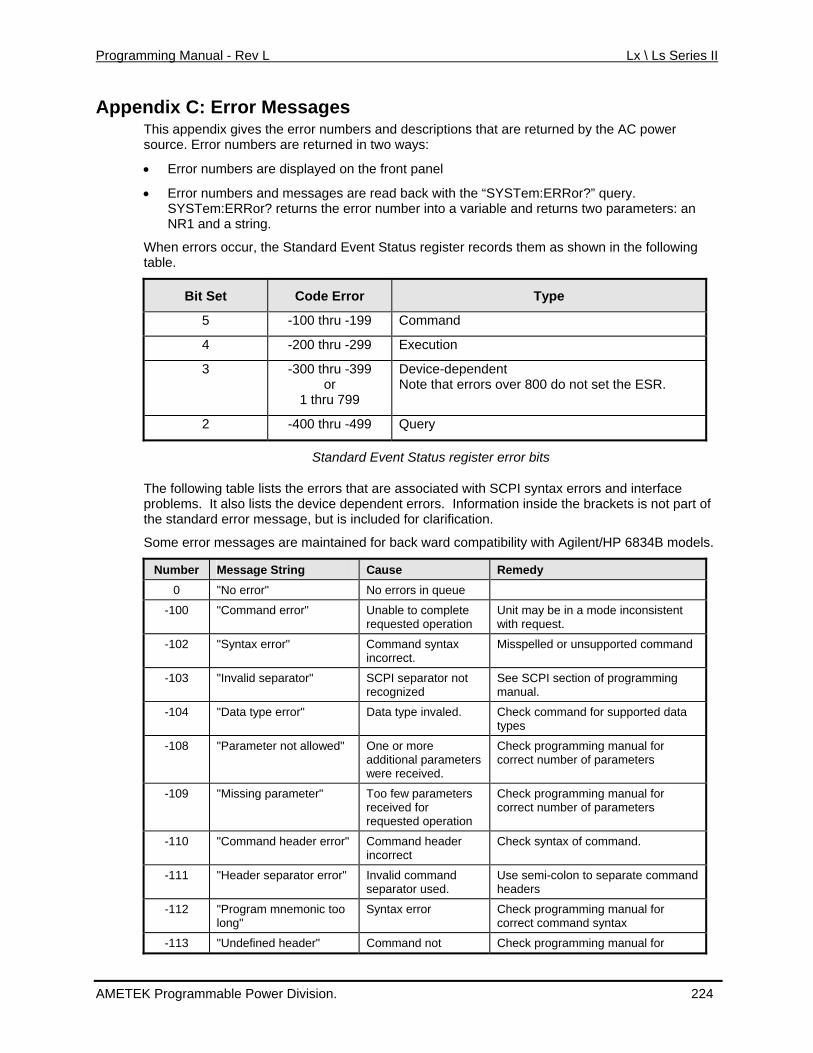
Programming Manual - Rev L Lx \ Ls Series II
Appendix C: Error Messages This appendix gives the error number s tha power sou rro ed in
•
• Error numbers and messages are read back with the “SYSTem:ERRor?” query. SYSTem:ERRor? returns the error number into a variable and returns two parameters: an
an
When errors occur, the Standard Eve ter reco e following tab
s and description t are returned by the ACrce. E r numbers are return two ways:
Error numbers are displayed on the front panel
NR1 d a string.
nt Status regis rds them as shown in thle.
Bit Set Code Error Type
5 -100 thru -199 Command
4 thru -29-200 9 Execution
3 -39
1 thru 799
es
-300 thruor
9 Device-dependNote that error
nt over 800 do not set the ESR.
2 -49-400 thru 9 Query
Standard Event Status register
The win errors tha h Sproblems. It also lists the device dependent errors. Information inside the brackets is not part of the standard error message, but is included for clarification.
Some error messages are maintained for back ward compatibility with Agilent/HP 6834B models.
error bits
follo g table lists the t are associated wit CPI syntax errors and interface
Number Message String Cause Remedy 0 "No error" No errors in queue
-100 "Command error" Unable to complete requested operation
Unit may be in a mode inconsistent with request.
-102 "Syntax error" Command syntaincorrect.
x
nd Misspelled or unsupported comma
-103 "Invalid separator" SCPI separator not
amming See SCPI section of progrrecognized manual.
-104 "Data type error" data Data type invaled. Check command for supportedtypes
-108 "Parameter not allowed" ore eters
al for Check programming manuOne or mcorrect number of parameters additional param
were received.
-109 "Missing parameter" parameters Check programming manual for Too fewcorrect number of parameters received for
requested operation
-110 "Command header error" Command header k syntax of command. Checincorrect
-111 "Header separator error" nd parate command Invalid comma Use semi-colon to seseparator used. headers
-112 "Program mnemonic too long" mand syntax
Syntax error Check programming manual for correct com
-113 "Undefined header" Command not k programming manual for Chec
AMETEK Programmable Power Division. 224
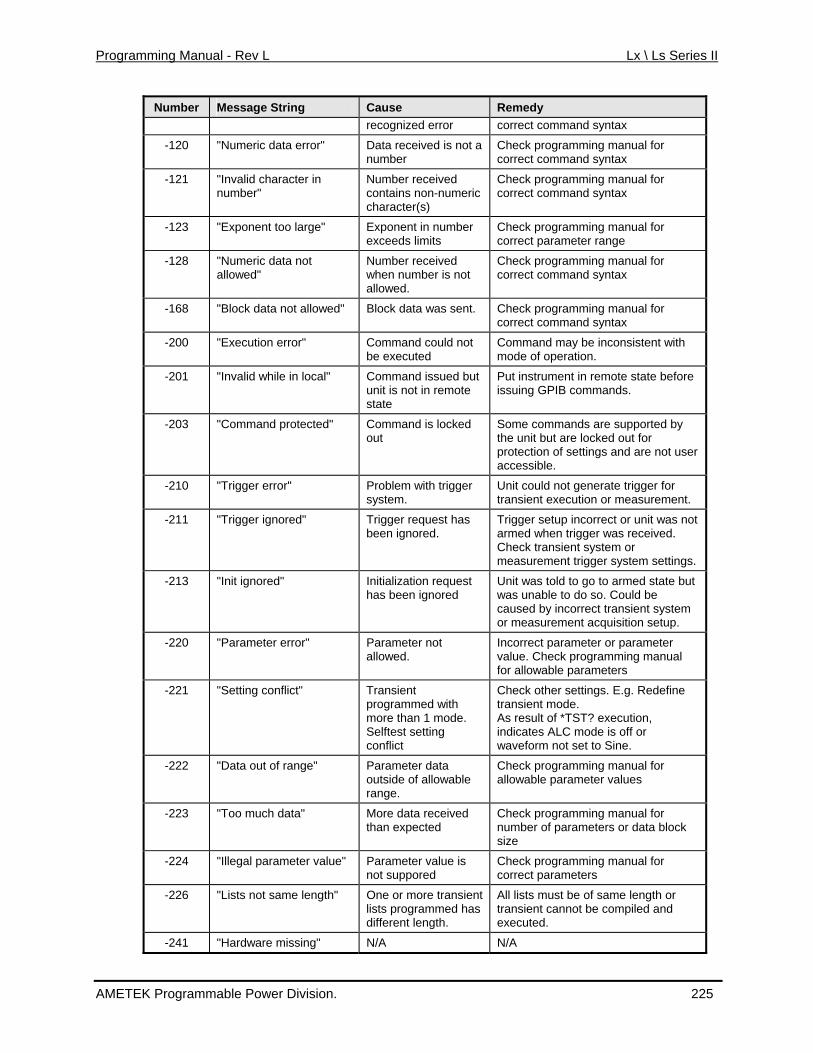
Programming Manual - Rev L Lx \ Ls Series II
Number Message String Cause Remedy recognized error correct command syntax
-120 "Numeric data error" t a r
programming manual for correct command syntax
Data received is nonumbe
Check
-121 "Invalid character in number" eric
Number received contains non-numcharacter(s)
Check programming manual for correct command syntax
-123 "Exponent too large" ber l for Exponent in numexceeds limits
Check programming manuacorrect parameter range
-128 "Numeric data not Number received allowed" when number is not
allowed.
Check programming manual for correct command syntax
-168 "Block data not allowed" data was sent. Check programming manual for Block correct command syntax
-200 "Execution error" Command could not be executed
Command may be inconsistent with mode of operation.
-201 "Invalid while in local" Command issued but unit is not in remote state
before Put instrument in remote stateissuing GPIB commands.
-203 "Command protected" Command is locked out
r accessible.
Some commands are supported by the unit but are locked out for protection of settings and are not use
-210 "Trigger error" Problem wisystem.
th trigger ent.
Unit could not generate trigger for transient execution or measurem
-211 "Trigger ignored" er request has been ignored. d when trigger was received.
system settings.
Trigg Trigger setup incorrect or unit was not armeCheck transient system or measurement trigger
-213 "Init ignored" Initialization request has been ignored
but
urement acquisition setup.
Unit was told to go to armed state was unable to do so. Could be caused by incorrect transient systemor meas
-220 "Parameter error" .
r Parameter not allowed
Incorrect parameter or parametevalue. Check programming manual for allowable parameters
-221 "Setting conflict" programmed with
conflict
t set to Sine.
Transient
more than 1 mode. Selftest setting
Check other settings. E.g. Redefinetransient mode. As result of *TST? execution, indicates ALC mode is off or waveform no
-222 "Data out of range" Parameter data outside of allowable
ter values
range.
Check programming manual forallowable parame
-223 More data received amming manual for umber of parameters or data block
"Too much data" than expected
Check progrnsize
-224 value" is not suppored
anual for correct parameters
"Illegal parameter Parameter value Check programming m
-226 ient d has mpiled and
All lists must be of same length or transient cannot be co
"Lists not same length" One or more translists programme
executed. different length.
-241 "Hardware missing" N/A N/A
AMETEK Programmable Power Division. 225
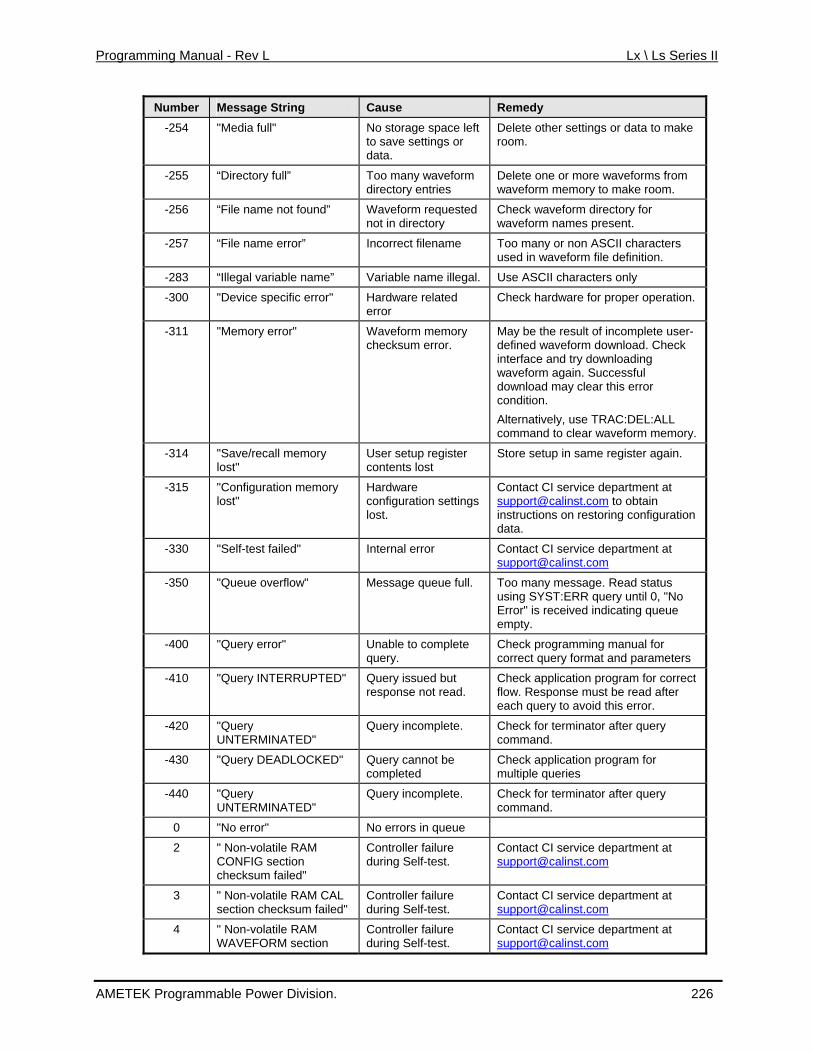
Programming Manual - Rev L Lx \ Ls Series II
Number Message String Cause Remedy -254 No storage space left
r Delete other settings or data to make "Media full" room. to save settings o
data.
-255 m
“Directory full” Too many waveformdirectory entries
Delete one or more waveforms frowaveform memory to make room.
-256 “File name not found” d directory
Check waveform directory for waveform names present.
Waveform requestenot in
-257 definition.
“File name error” Incorrect filename Too many or non ASCII charactersused in waveform file
-283 “Illegal variable name” a al. Use ASCII characters only Vari ble name illeg
-300 on. "Device specific error" Hardware related error
Check hardware for proper operati
-311 "Memory error" ksum error.
May be the result of incomplete user-defined waveform download. Check
is error condition.
ry.
Waveform memorychec
interface and try downloading waveform again. Successful download may clear th
Alternatively, use TRAC:DEL:ALL command to clear waveform memo
-314 "Save/recall memory lost"
nts lost
Store setup in same register again. User setup registerconte
-
Contact CI service department at [email protected] to obtain
315 "Configuration memory lost"
Hardware configuration settingslost. instructions on restoring configuration
data.
-330 "Self-test failed" Internal error Contact CI service department at [email protected]
-350 "Queue overflow" Message queue full. using SYST:ERR query until 0, "No Too many message. Read status
Error" is received indicating queue empty.
-400 "Query error" for ameters
Unable to complete query.
Check programming manualcorrect query format and par
-410 "Query INTERRUPTED" Check application program for correct after
Query issued but response not read. flow. Response must be read
each query to avoid this error.
-420 "Query UNTERMINATED"
Query incomplete. Check for terminator after query command.
-430 EADLOCKED" Query cannot be Check application program for "Query Dcompleted multiple queries
-440 r terminator after query command.
"Query UNTERMINATED"
Query incomplete. Check fo
0 "No error" eue No errors in qu
2 " Non-volatile RAM CONFIG section checksum failed"
Controller failure during Self-test.
Contact CI service department at [email protected]
3 latile RAM CAL
ailure
Contact CI service department at " Non-vosection checksum failed"
Controller fduring Self-test. [email protected]
4 WAVEFORM section -test.
Contact CI service department at [email protected]
" Non-volatile RAM Controller failure during Self
AMETEK Programmable Power Division. 226
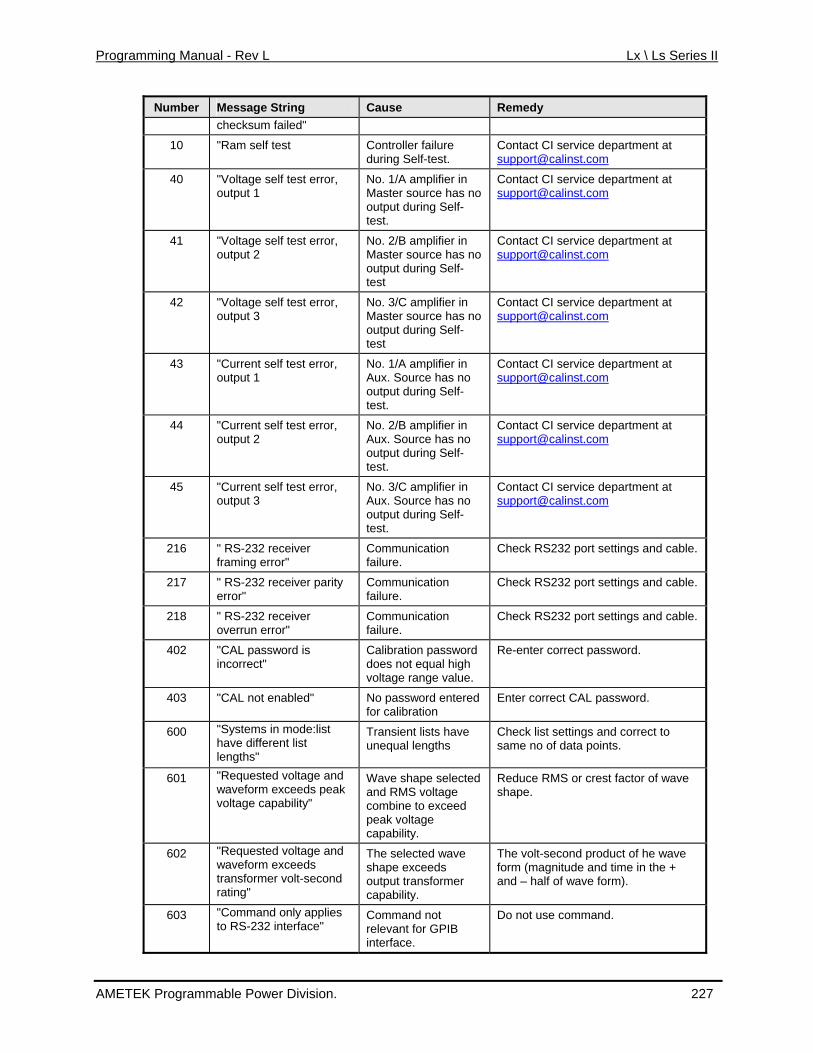
Programming Manual - Rev L Lx \ Ls Series II
Number Message String Cause Remedy checksum failed"
10 g Self-test.
t CI service department at [email protected]
"Ram self test Controller failure durin
Contac
40 "Voltage self test error, output 1
No. 1/A amplifier in Master source has noutput during Sel
o f-
test.
Contact CI service department at [email protected]
41 self test error, plifier in no
-
ment at "Voltage output 2
No. 2/B amMaster source hasoutput during Selftest
Contact CI service [email protected]
42 "Voltage self tesoutput 3
t error, o
ontact CI service department at No. 3/C amplifier in Master source has noutput during Self-test
43 "Current self test error, output 1
No. 1/A amplifier in Aux. Source has no output during Self-test.
Contact CI service department at [email protected]
44 "Current self test error, Contact CI service department at output 2
No. 2/B amplifier in Aux. Source has no output during Self-test.
45 "Current self test error, output 3
/C amplifier in has no
ervice department at No. 3Aux. Sourceoutput during Self-test.
Contact CI [email protected]
216 " RS-232 receiver Communication RS232 port settings and cable. framing error" failure.
Check
217 " RS-232 receiver parity error"
tion failure.
e. Communica Check RS232 port settings and cabl
218 " RS-232 receiver overrun error"
Communication failure.
Check RS232 port settings and cable.
402 "CAL password is ord incorrect"
Calibration passwdoes not equal high voltage range value.
Re-enter correct password.
403 "CAL not enabled" No password entered for calibration
Enter correct CAL password.
600 "Systems in mode:list have different list
e
lengths"
Transient lists havunequal lengths
Check list settings and correct to same no of data points.
601 "Requested voltage and waveform exceeds peak voltage capability"
Wave shape selected and RMS voltage combine to exceed peak voltage capability.
Reduce RMS or crest factor of wave shape.
602 "Requested voltage and waveform exceeds transformer volt-second rating"
output transformer capability.
The selected wave shape exceeds
The volt-second product of he wave form (magnitude and time in the + and – half of wave form).
603 "Command only applies to RS-232 interface" B
Command not relevant for GPIinterface.
Do not use command.
AMETEK Programmable Power Division. 227
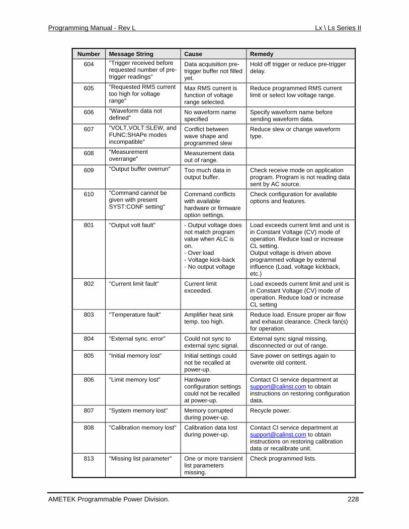
Programming Manual - Rev L Lx \ Ls Series II
Number Message String Cause Remedy 604 "Trigger received befor
requested number of pre-e
trigger readings"
n pre-
Data acquisitiotrigger buffer not filledyet.
Hold off trigger or reduce pre-trigger delay.
605 "Requested RMS current Max RMS current is rammed RMS current too high for voltage range"
function of voltage range selected.
Reduce proglimit or select low voltage range.
606 "Waveform data not defined"
e specified
No waveform nam Specify waveform name beforesending waveform data.
607 "VOLT,VOLT:SLEW, and FUNC:SHAPe modes incompatible"
rm Conflict between wave shape and programmed slew
Reduce slew or change wavefotype.
608 "Measurement overrange"
Measurement dataout of range.
609 "Output buffer overrun" Too much dataoutput buffer.
in n ata
sent by AC source.
Check receive mode on applicatioprogram. Program is not reading d
610 "Command cannot be given with present SYST:CONF setting"
cts
r firmware
Command confliwith available hardware ooption settings.
Check configuration for available options and features.
801 "Output volt fault" es
ack ge
V) mode of
Output voltage is driven above programmed voltage by external influence (Load, voltage kickback, etc.)
- Output voltage donot match program value when ALC is on. - Over load - Voltage kick-b- No output volta
Load exceeds current limit and unit is in Constant Voltage (Coperation. Reduce load or increase CL setting.
802 "Current limit fault" e
Current limit exceeded.
Load exceeds current limit and unit isin Constant Voltage (CV) mode ofoperation. Reduce load or increasCL setting
803 "Temperature fault" Reduce load. Ensure proper air flow and exhaust clearance. Check fan(s)
Amplifier heat sink temp. too high.
for operation.
804 "External sync. error" l.
l sync signal missing, Could not sync to external sync signa
Externadisconnected or out of range.
805 "Initial memory lost" s could
Initial settingnot be recalled atpower-up.
Save power on settings again to overwrite old content.
806 "Limit memory lost" Hardware
er-up.
t CI service department at configuration settingscould not be recalled at pow
[email protected] to obtaininstructions on restoring configuratiodata.
n
807 "System memory lost" Memory corrupted during power-up.
Recycle power.
808 "Calibration memory lost" ata lost during power-up.
Contact CI service department at [email protected]
Calibration d to obtain
restoring calibration data or recalibrate unit. instructions on
813 "Missing list parameter" One or more transient list parameters missing.
Check programmed lists.
AMETEK Programmable Power Division. 228
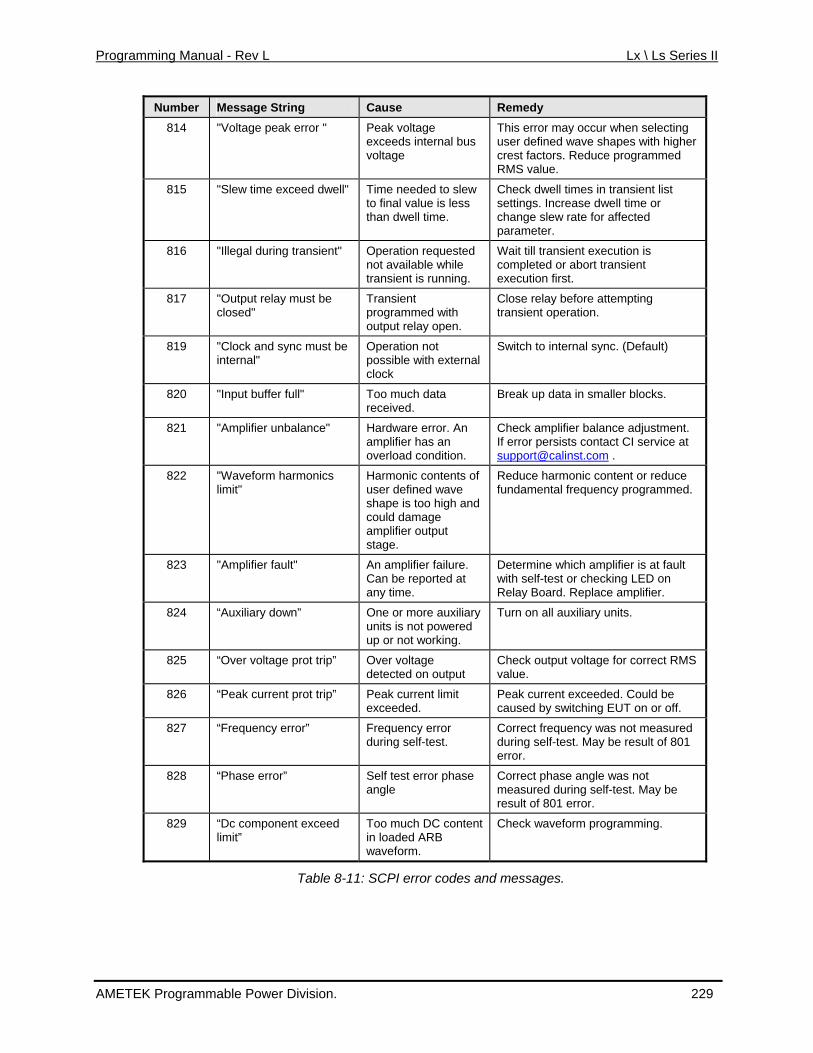
Programming Manual - Rev L Lx \ Ls Series II
Number Message String Cause Remedy 814 "Voltage peak error " Peak voltage
exceeds internal bus voltage
This error may occur when selecting user defined wave shapes with higher crest factors. Reduce programmed RMS value.
815 "Slew time exceed dwell" Time needed to slew to final value is less
Check dwell times in transient list settings. Increase dwell time or
than dwell time. change slew rate for affected parameter.
816 "Illegal during transient" Operation requested not available while transient is running.
Wait till transient execution is completed or abort transient execution first.
817 "Output relay must be closed"
Transient programmed with output relay open.
Close relay before attempting transient operation.
819 "Clock and sync must be internal"
Operation not possible with external
Switch to internal sync. (Default)
clock
820 "Input buffer full" Too much data Break up data in smaller blocks. received.
821 "Amplifier unbalance" Hardware error. An amplifier has an overload condition.
Check amplifier balance adjustment. If error persists contact CI service at [email protected] .
822 "Walimit user defined wave
amplifier output
educe harm nic content or reduce fundamental frequency programmed.
veform harmonics Harmonic contents of R"
shape is too high and could damage
stage.
o
823 "Amplifier fault" An amplifier failure. Determine which amCan be reported at any time.
with self-test or cheRelay Board. Repla
plifier is at fault cking LED on ce amplifier.
824 “Auxiliary d e or more auxiliary Turn oown” Onuniup or not w
n all auxiliary units. ts is not powered
orking.
825 “Over voltage prot trip” Over voltage detected on output
Check output voltage for correct RMS value.
826 “Peak current prot trip” Peak current limit exceeded.
Peak current exceeded. Could be caused by switching EUT on or off.
827 “Frequency error” Frequency error Correct frequency was not measured 801 during self-test. during self-test. May be result of
error.
828 “Phase error” Self test error phase angle
Correct phase angle was not measured during self-test. May be result of 801 error.
829 “Dc component exceed lim
Too much DC content in loaded ARB waveform.
Check waveform programming. it”
Tab 1: SCPI e odes and
le 8-1 rror c messages.
AMETEK Programmable Power Division. 229
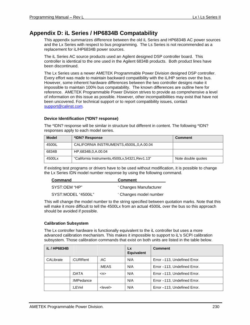
Programming Manual – Rev L Lx \ Ls Series II
Appen S ries / HP 834B Co atability This appendix summarizes difference betwee eries and HP6834B AC power sources and the Lx Series with respect to bus program The Lsreplacement for iL/HP6834B power sources.
The iL Series AC source products used an Agilent designed DSP controller board. This controller is identical to the one used in the Agilent 6834B p been discontinued.
The Lx Series uses a newer AMETEK Programmable Power Division designed DSP controller. E ery effort wa to main in backward c tibility w L/HP series over the bus. H wever, some t hardw es een the it impossible to maintain 100% bus compatability.reference. AMETEK Programmable Power Division strives to provide as comprehensive a level o information o this issue as e other inco have not
dix D: iL e 6 mpn the old iL Sming. Series is not recommended as a
roducts. Both product lines have
v s made ta ompa ith the io inheren are differenc betw two controller designs make
The known differences are outline here for
f n possible. How ver, mpatibilities may exist that been uncovered. For technical support or to report compatibility issues, contact [email protected].
Device Identification (*IDN? response)
The *IDN? response will be similar in structure but different in content. The following *IDN? responses apply to each model series.
Model *IDN? Response Comment
4500iL C LIFORNIA INSTRUMENTS,4500IL,0,A.00.04 A
6834B HP,6834B,0,A.00.04
4500Lx “California Instruments,4500Lx,54321,Rev1.13” tes Note double quo
If existing test programs or drivers have to be used without modification, it is possible to change t Lx Series ID del numb nse by us llowin
Command me
he N mo er respo ing the fo g command.
Com nt
SYST:OEM “HP” nufactur
SYST:MODEL “4500iL” ‘ Changes model number
T is will chang del nu ber to the string s d betwe at this will make it more difficult to tell the 4500Lx from an actual 4500iL over the bus so this approach should be avoided if possible.
Calibration Subsystem
ware is functionally equivalent to the iL controller but uses a more
‘ Changes Ma er
h e the mo m pecifie en quotation marks. Note th
The Lx controller hardadvanced calibration mechanism. This makes it impossible to support to iL’s SCPI calibration subsystem. Those calibration commands that exist on both units are listed in the table below.
iL / HP6834B Lx Equivalent
Comment
CALibrate :CURRent :AC N/A Error –113, Undefined Error.
:MEAS N/A Error –113, Undefined Error.
:DATA <n> N/A Error –113, Undefined Error.
:IMPedance N/A Error –113, Undefined Error.
:LEVel <level> N/A Error –113, Undefined Error.
AMETEK Programmable Power Division. 230
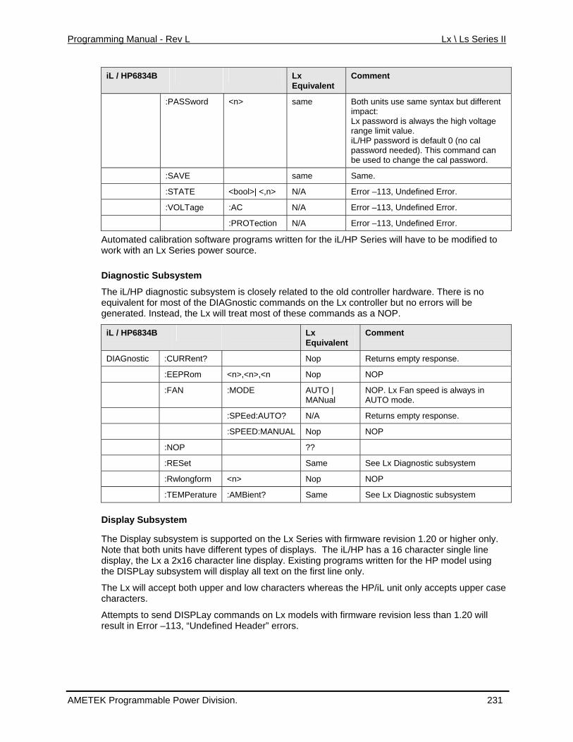
Programming Manual - Rev L Lx \ Ls Series II
iL / HP6834B Lx Equivalent
Comment
:PASSword <n> sam
be used to change the cal password.
e Both units use same syntax but different impact: Lx password is always the high voltage range limit value. iL/HP password is default 0 (no cal password needed). This command can
:SAVE same Same.
:STATE <bool>| <,n> N/A Error –113, Undefined Error.
:VOLTage :AC N/A Error –113, Undefined Error.
:PROTection N/A Error –113, Undefined Error.
Automated calibration software programs written
The iL/HP diagnostic subsystem is closely relatealent for most of the DIAGnostic commands
of thes
for the iL/HP Series will have to be modified to work with an Lx Series power source.
Diagnostic Subsystem
d to the old controller hardware. There is no equiv on the Lx controller but no errors will be generated. Instead, the Lx will treat most e commands as a NOP.
iL / HP6834B Lx Equivalent
Comment
DIAGnostic :CURRent? Nop Returns empty response.
:EEPRom <n>,<n>,<n Nop NOP
:FAN :MODE AUTO | NOP. Lx Fan speed is always in MANual AUTO mode.
:SPEed:AUTO? N/A Returns empty response.
:SPEED:MANUAL Nop NOP
:NOP ??
:RESet Same See Lx Diagnostic subsystem
:Rwlongform <n> Nop NOP
:TEMPerature :AMBient? Same See Lx Diagnostic subsystem
Display Subsystem
The Display subsystem is supported on the Lx Sof displalay. Existing programs written for the HP model using xt on the
aracters
n Lx moderrors.
eries with firmware revision 1.20 or higher only. Note that both units have different types ys. The iL/HP has a 16 character single line display, the Lx a 2x16 character line dispthe DISPLay subsystem will display all te first line only.
The Lx will accept both upper and low ch whereas the HP/iL unit only accepts upper casecharacters.
Attempts to send DISPLay commands oresult in Error –113, “Undefined Header”
els with firmware revision less than 1.20 will
AMETEK Programmable Power Division. 231
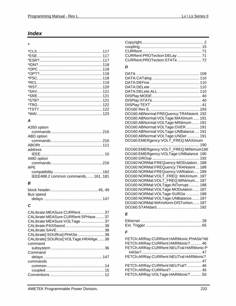
Programming Manual - Rev L Lx \ Ls Series II
Index
*
*CLS.............................................................117 *ESE.............................................................117 *ESR?...........................................................117 *IDN?............................................................118 *OPC ............................................................118 *OPT?...........................................................118 *PSC.............................................................118 *RCL.............................................................119 *RST.............................................................120 *SAV.............................................................121 *SRE.............................................................121 *STB?...........................................................121 *TRG ............................................................122 *TST? ...........................................................122 *WAI .............................................................123
A
A350 option commands ................................................216
ABD option commands ................................................216
ABORt ..........................................................111 address
IEEE............................................................10 AMD option
88.2 common commands.......161, 181
Librate[:SOURce]:PHASe .........................38 Librate[:SOURce]:VOLTage:HRANge ......38
d
C
s
Conventions ...................................................12
C
Play:MODE .............................................. 40 .............................................. 40
EXT................................................ 41 D
rmal:FREQuency:TRANsient. 192 DDD
TCh:ARRay:CURRent:HARMonic? .......... 46
FEFETCh:ARRay:VOLTage:HARMonic? .......... 50
commands ................................................216 APE
compatibility..............................................162 IEEE4
B
block header.............................................45, 49 Bus speed
delays .......................................................147
C
CALibrate:MEASure:CURRent ......................37 CALibrate:MEASure:CURRent:SPHase........37 CALibrate:MEASure:VOLTage ......................37 CALibrate:PASSword.....................................38 CALibrate:SAVE.............................................38 CACAcomman
subsystem ..................................................36 ommand delays .......................................................147
commandcommon......................................................14 coupled .......................................................15
Ccoupling.......................................
opyright.......................................................... 2 ................... 15
URRent........................................................ 71 CURRent:PROTection:DELay....................... 71 CURRent:PROTection:STATe ...................... 72
D
DATA ........................................................... 109 DATA:CATalog ............................................ 110 DATA:DEFine .............................................. 110 DATA:DELete .............................................. 110 DATA:DELete:ALL....................................... 110 DISDISPlay:STATeDISPlay:T
O160 Rev E............................................... 193 DO160:ABNo
O160:ABNormal:VOLTage:MAXimum...... 191 O160:ABNormal:VOLTage:MINimum....... 191 O160:ABNormal:VOLTage:OVER ............ 191
DO160:ABNormal:VOLTage:UNBalance .... 191 DO160:ABNormal:VOLTage:UNDer ........... 191 DO160:EMERgency:VOLT_FREQ:MAXimum
................................................................. 190 DO160:EMERgency:VOLT_FREQ:MINimum190 DO160:EMERgency:VOLTage:UNBalance 190 DO160:GROup ............................................ 192 DO160:NORMal:FREQuency:MODulation.. 188 DO160:NORMal:FREQuency:TRANsient ... 188 DO160:NORMal:FREQuency:VARiation..... 189 DO160:NORMal:VOLT_FREQ: MAXimum . 187 DO160:NORMal:VOLT_FREQ:MINimum.... 187 DO160:NORMal:VOLTage:INTerrupt.......... 188 DO160:NORMal:VOLTage:MODulation ...... 187 DO160:NORMal:VOLTage:SURGe............. 188 DO160:NORMal:VOLTage:UNBalance....... 187 DO160:NORMal:WAVeform:DISTortion...... 187 DO160:STANdard........................................ 192
E
Ethernet ......................................................... 28 Ext. Trigger .................................................... 65
F
FETCh:ARRay:CURRent:HARMonic:PHASe?46 FEFETCh:ARRay:CURRent:NEUTral:HARMonic:P
HASe? ........................................................ 47 TCh:ARRay:CURRent:NEUTral:HARMonic?FE................................................................... 47
FETCh:ARRay:CURRent:NEUTral?.............. 46 TCh:ARRay:CURRent?............................. 45
AMETEK Programmable Power Division. 232
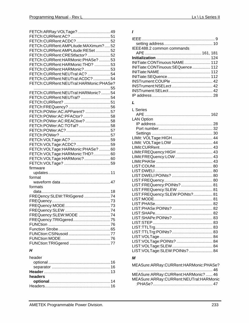
Programming Manual - Rev L Lx \ Ls Series II
FETCh:ARRay:VOLTage?.............................49 TCh:CURRent:AC? ...................................51 FE
FETCh:CURRent:NEUTral? ..........................54
FE
FETCh:VOLTage:HARMonic:PHASe? ..........60
FETCh:VOLTage? .........................................59
formats
L
M
. .
FETCh:CURRent:ACDC? ..............................52 FETCh:CURRent:AMPLitude:MAXimum?.....52 FETCh:CURRent:AMPLitude:RESet .............52 FETCh:CURRent:CREStfactor? ....................52 FETCh:CURRent:HARMonic:PHASe? ..........53 FETCh:CURRent:HARMonic:THD? ..............53 FETCh:CURRent:HARMonic? .......................53 FETCh:CURRent:NEUTral:AC? ....................54 FETCh:CURRent:NEUTral:ACDC? ...............54 FETCh:CURRent:NEUTral:HARMonic:PHASe?
....................................................................55 FETCh:CURRent:NEUTral:HARMonic? ........54
FETCh:CURRent? .........................................51 FETCh:FREQuency? .....................................56 FETCh:POWer:AC:APParent? ......................57
TCh:POWer:AC:PFACtor? ........................58 FETCh:POWer:AC:REACtive? ......................58 FETCh:POWer:AC:TOTal?............................58 FETCh:POWer:AC?.......................................57 FETCh:POWer? .............................................57 FETCh:VOLTage:AC? ...................................59 FETCh:VOLTage:ACDC? ..............................59
FETCh:VOLTage:HARMonic:THD?...............60 FETCh:VOLTage:HARMonic? .......................60
firmware updates.......................................................11
format waveform data ............................................47
data.............................................................18 FREQency:SLEW:TRIGgered .......................74 FREQuency....................................................73 FREQuency:MODE........................................73 FREQuency:SLEW ........................................74 FREQuency:SLEW:MODE ............................74 FREQuency:TRIGgered.................................75 FUNCtion .......................................................76 Function Strobe..............................................65 FUNCtion:CSINusoid .....................................77 FUNCtion:MODE............................................76 FUNCtion:TRIGgered ....................................77
H
header optional .......................................................16 separator ....................................................16
Header ...........................................................13 headers
optional......................................................14 Headers..........................................................16
I
.......................................... 9 IEEE.......................setting address........................................... 10
commands IEEE488.2 commonAPE .................................................. 161, 181
...................................... 124 Initialization ..........INITiate:CONTinuous:NAME....................... 112 INITiate:CONTinuous:SEQuence................ 112 INITiate:NAME............................................. 112 INITiate:SEQuence...................................... 112 INSTrument:COUPle ..................................... 42 INSTrument:NSELect .................................... 42 INSTrument:SELect....................................... 42
IP address...................................................... 28
L Series APE .......................................................... 162
LAN Option IP address .................................................. 28 Port number................................................ 32 Settings ...................................................... 30
LIMit: VOLTage:HIGH.................................... 44 LIMit: VOLTage:LOW .................................... 44
........................................... 43 LIMit:CURRent....LIMit:FREQuency:HIGH ................................ 43 LIMit:FREQuency:LOW ................................. 43 LIMit:PHASe .................................................. 43
........................................... 80 LIST:COUNt........LIST:DWELl ................................................... 80
LIST:DWELl:POINts? .................................... 80LIST:FREQuency........................................... 80 LIST:FREQuency:POINts? ............................ 81 LIST:FREQuency:SLEW ............................... 81 LIST:FREQuency:SLEW:POINts?................. 81 LIST:MODE.................................................... 81 LIST:PHASe................................................... 82 LIST:PHASe:POINts?.................................... 82 LIST:SHAPe................................................... 82 LIST:SHAPe:POINts?.................................... 83
LIST:STEP..................................................... 83LIST:TTLTrg................................................... 83
LIST:TTLTrg:POINts?.................................... 83LIST:VOLTage............................................... 84 LIST:VOLTage:POINts? ................................ 84 LIST:VOLTage:SLEW.................................... 84 LIST:VOLTage:SLEW:POINts?..................... 84
MEASure:ARRay:CURRent:HARMonic:PHASe?................................................................... 46
MEASure:ARRay:CURRent:HARMonic? ...... 46 MEASure:ARRay:CURRent:NEUTral:HARMonic
......... ................................ . 47 :PHASe?.........
AMETEK Programmable Power Division. 233
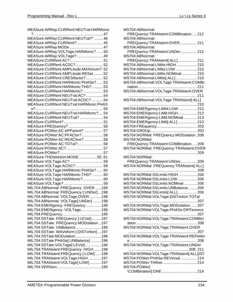
Programming Manual - Rev L Lx \ Ls Series II
M
ay:VOLTage?.........................49 M
:ACDC? ..........................52 M
ASure:CURRent:AMPLitude:RESet .........52 ASure:CURRent:CREStfactor? ................52
C:APParent? ..................57 ASure:POWer:AC:PFACtor? ....................58
LTage:HARMonic:PHASe? ......60 M
........198 704:EMERgency :FREQuency ..............199
uency.....................................195 L704:SSTate: FREQuency [:LEVel].........197
L704:TRANsient:FREQuency :HIGH.......198
MM
M
M
LL] .................... 210 M
M
M
M
M
:TRANsient:OVER
704:NORMal:VOLTage:TRANsient:UNDer......................................................... 208, 211
OWer[
EASure:ARRay:CURRent:NEUTral:HARMonic?..................................................................47
MEASure:ARRay:CURRent:NEUTral?".........46 MEASure:ARRay:CURRent?.........................45 MEASure:ARRay:MODe................................47 MEASure:ARRay:VOLTage:HARMonic? ......50 MEASure:ARR
EASure:CURRent:AC? ...............................51 MEASure:CURRent
EASure:CURRent:AMPLitude:MAXimum?.52 MEMEMEASure:CURRent:HARMonic:PHASe? ......53 MEASure:CURRent:HARMonic:THD? ..........53 MEASure:CURRent:HARMonic? ...................53 MEASure:CURRent:NEUTral:AC? ................54 MEASure:CURRent:NEUTral:ACDC? ...........54 MEASure:CURRent:NEUTral:HARMonic:PHAS
e?................................................................55 MEASure:CURRent:NEUTral:HARMonic? ....54 MEASure:CURRent:NEUTral? ......................54 MEASure:CURRent? .....................................51 MEASure:FREQuency? .................................56 MEASure:POWer:AMEMEASure:POWer:AC:REACtive? ..................58 MEASure:POWer:AC:TOTal?........................58 MEASure:POWer:AC?...................................57 MEASure:POWer? .........................................57 MEASure:THDistortion:MODE.................55, 61 MEASure:VOLTage:AC? ...............................59 MEASure:VOLTage:ACDC? ..........................59 MEASure:VO
EASure:VOLTage:HARMonic:THD? ..........60 MEASure:VOLTage:HARMonic? ...................60 MEASure:VOLTage? .....................................59 MIL704:ABNormal :FREQuency :OVER......199 MIL704:ABNormal :FREQuency [:UNDer]...198 MIL704:ABNormal :VOLTage:OVER...........198 MIL704:ABNormal :VOLTage[:UNDer]MILMIL704:EMERgency :VOLTage...................199 MIL704:FREQMIMIL704:SSTate: FREQuency:MODulation ..197 MIL704:SSTate: UNBalance........................196 MIL704:SSTate: WAVeform [:DISTortion] ...197
STate:MODulation ........................196 MIL704:SMIL704:SSTate:PHASe[:UNBalance] ..........196
...............196 MIL704:SSTate:VOLTage[:LEVel]MIMIL704:TRANsient:FREQuency [:LOW]......198 MIL704:TRANsient:VOLTage:HIGH ............197
IL704:TRANsient:VOLTage[:LOW]...........197 IL704:VERSion..........................................195
S704:ABNormal: FREQuency:TRANsient:COMBination..... 212 S704:ABNormal: FREQuency:TRANsient:OVER................ 211
MS704:ABNormal: FREQuency:TRANsient:UNDer ............... 212
MS704:ABNormal: FREQuency:TRANsient[:ALL].................. 211
MS704:ABNormal:LIMits:HIGH ................... 210 MS704:ABNormal:LIMits:LOW .................... 210 MS704:ABNormal:LIMits:NOMinal .............. 210 MS704:ABNormal:LIMits[:A
S704:ABNormal:VOLTage:TRANsient:COMBination........................................................ 211
MS704:ABNormal:VOLTage:TRANsient:OVER................................................................. 211
MS704:ABNormal:VOLTage:TRANsient[:ALL]................................................................. 210
S704:EMERgency:LIMIit:LOW ................. 213 MS704:EMERgency:LIMit:HIGH.................. 213
S704:EMERgency:LIMit:NOMinal ............ 213 MS704:EMERgency:LIMit[:ALL] .................. 213
S704:FREquency...................................... 203 MS704:GROUp............................................ 203
S704:NORMal: FREQuency:MODulation. 208 MS704:NORMal:
FREQuency:TRANsient:COMBination..... 209 MS704:NORMal: FREQuency
................................................................. 209 MS704:NORMal:
FREQuency:TRANsient:UNDer ............... 209 MS704:NORMal: FREQuency:TRANsient[:ALL]
................................................................. 208 MS704:NORMal:SSLimits:HIGH ................. 206 MS704:NORMal:SSLimits:LOW .................. 206 MS704:NORMal:SSLimits:NOMinal ............ 206 MS704:NORMal:SSLimits:UNBalance ........ 206 MS704:NORMal:SSLimits[:ALL] .................. 206 MS704:NORMal:VOLTage:DISTortion:TOTal
................................................................. 207 MS704:NORMal:VOLTage:MODulation ...... 207 MS704:NORMal:VOLTage:PHASe:DIFFerence
................................................................. 207 MS704:NORMal:VOLTage:TRANsient:COMBin
ation.......................................................... 208 MS704:NORMal:VOLTage:TRANsient:OVER
................................................................. 207 MS704:NORMal:VOLTage:TRANsient:REPetitiv
e ............................................................... 208 MS
MS704:NORMal:VOLTage:TRANsient[:ALL]207 MS704:POWer:PHASe:REVersal ............... 214 MS704:POWer:THRee ................................ 214 MS704:P
\COMBination]:ONE ................................. 214
AMETEK Programmable Power Division. 234
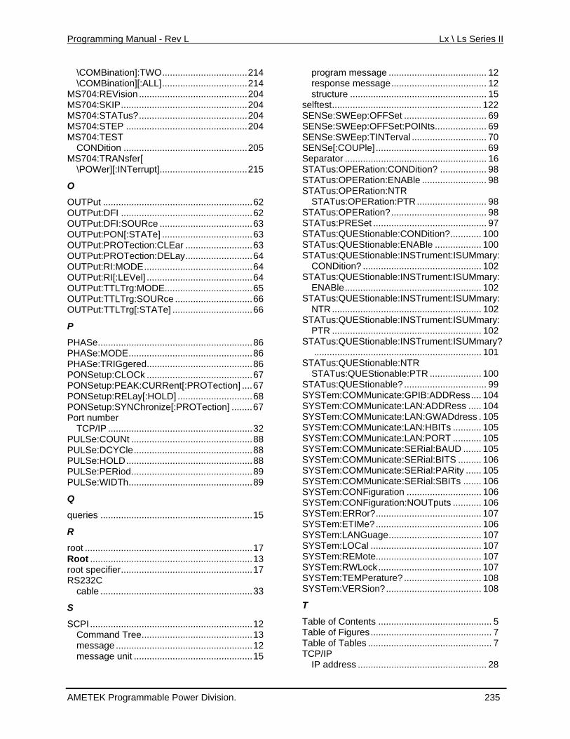
Programming Manual - Rev L Lx \ Ls Series II
\COMBination]:TWO.................................214 \COMBination][:ALL].................................214
MS704:REVision ..........................................204 MS704:SKIP.................................................204 MS704:STATus?..........................................204 MS704:STEP ...............................................204 MS704:TEST
CONDition ................................................205 MS704:TRANsfer[
\POWer][:INTerrupt]..................................215
O
OUTPut ..........................................................62 OUTPut:DFI ...................................................62 OUTPut:DFI:SOURce ....................................63 OUTPut:PON[:STATe] ...................................63 OUTPut:PROTection:CLEar ..........................63 OUTPut:PROTection:DELay..........................64 OUTPut:RI:MODE..........................................64 OUTPut:RI[:LEVel] .........................................64 OUTPut:TTLTrg:MODE..................................65 OUTPut:TTLTrg:SOURce ..............................66
UTPut:TTLTrg[:STATe] ...............................66
P
PHASe............................................................86 PHASe:MODE................................................86 PHASe:TRIGgered.........................................86 PONSetup:CLOCk .........................................67 PONSetup:PEAK:CURRent[:PROTection] ....67 PONSetup:RELay[:HOLD] .............................68 PONSetup:SYNChronize[:PROTection] ........67 Port number
TCP/IP ........................................................32 PULSe:COUNt ...............................................88 PULSe:DCYCle..............................................88 PULSe:HOLD.................................................88 PULSe:PERiod...............................................89 PULSe:WIDTh................................................89
Q
queries ...........................................................15
R
root .................................................................17 Root ...............................................................13 root specifier...................................................17 RS232C
cable ...........................................................33
S
SCPI ...............................................................12 Command Tree...........................................13 message .....................................................12 message unit ..............................................15
ssage ...................................... 12
NSe:SWEep:OFFSet ................................ 69 ep:OFFSet:POINts.................... 69
Tus:QUEStionable:INSTrument:ISUMmary:102
STATus:QUEStionable:INSTrument:ISUMmary:PTR .......................................................... 102
STATus:QUEStionable:INSTrument:ISUMmary?................................................................. 101
STATus:QUEStionable:NTR STATus:QUEStionable:PTR .................... 100
STATus:QUEStionable? ................................ 99 SYSTem:COMMunicate:GPIB:ADDRess.... 104 SYSTem:COMMunicate:LAN:ADDRess ..... 104 SYSTem:COMMunicate:LAN:GWADdress . 105 SYSTem:COMMunicate:LAN:HBITs ........... 105 SYSTem:COMMunicate:LAN:PORT ........... 105 SYSTem:COMMunicate:SERial:BAUD ....... 105 SYSTem:COMMunicate:SERial:BITS ......... 106 SYSTem:COMMunicate:SERial:PARity ...... 105 SYSTem:COMMunicate:SERial:SBITs ....... 106 SYSTem:CONFiguration ............................. 106 SYSTem:CONFiguration:NOUTputs ........... 106 SYSTem:ERRor?......................................... 107 SYSTem:ETIMe?......................................... 106 SYSTem:LANGuage.................................... 107 SYSTem:LOCal ........................................... 107 SYSTem:REMote......................................... 107 SYSTem:RWLock........................................ 107 SYSTem:TEMPerature? .............................. 108 SYSTem:VERSion?..................................... 108
T
Table of Contents ............................................ 5 Table of Figures............................................... 7 Table of Tables ................................................ 7 TCP/IP
IP address .................................................. 28
O
program meresponse message..................................... 12 structure ..................................................... 15
selftest.......................................................... 122 SESENSe:SWESENSe:SWEep:TINTerval ............................. 70 SENSe[:COUPle] ........................................... 69 Separator ....................................................... 16 STATus:OPERation:CONDition? .................. 98 STATus:OPERation:ENABle ......................... 98 STATus:OPERation:NTR
STATus:OPERation:PTR........................... 98 STATus:OPERation?..................................... 98 STATus:PRESet ............................................ 97 STATus:QUEStionable:CONDition?............ 100 STATus:QUEStionable:ENABle .................. 100 STATus:QUEStionable:INSTrument:ISUMmary:
CONDition? .............................................. 102 STA
ENABle.....................................................STATus:QUEStionable:INSTrument:ISUMmary:
NTR .......................................................... 102
AMETEK Programmable Power Division. 235
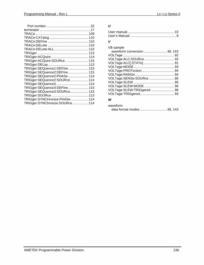
Programming Manual - Rev L Lx \ Ls Series II
AMETEK Programmable Power Division. 236
Port number................................................32 terminator .......................................................17 TRACe..........................................................109 TRACe:CATalog ..........................................110 TRACe:DEFine ............................................110 TRACe:DELete ............................................110 TRACe:DELete:ALL.....................................110 TRIGger .......................................................113 TRIGger:ACQuire.........................................114 TRIGger:ACQuire:SOURce .........................115 TRIGger:DELay............................................113 TRIGger:SEQuence1:DEFine......................115 TRIGger:SEQuence2:DEFine......................115 TRIGger:SEQuence2:PHASe ......................114 TRIGger:SEQuence2:SOURce....................114 TRIGger:SEQuence3...................................114 TRIGger:SEQuence3:DEFine......................115 TRIGger:SEQuence3:SOURce....................115 TRIGger:SOURce ........................................113 TRIGger:SYNCHronize:PHASe...................114 TRIGger:SYNChronize:SOURce .................114
U
User manual................................................... 10 User's Manual .................................................. 8
V
VB sample waveform conversion ......................... 48, 143
VOLTage........................................................ 92 VOLTage:ALC:SOURce ................................ 92 VOLTage:ALC[:STATe] ................................. 91 VOLTage:MODE............................................ 93 VOLTage:PROTection................................... 94 VOLTage:RANGe .......................................... 94 VOLTage:SENSe:SOURce ........................... 95 VOLTage:SLEW ............................................ 95 VOLTage:SLEW:MODE ................................ 96 VOLTage:SLEW:TRIGgered ......................... 96 VOLTage:TRIGgered..................................... 93
W
waveform data format modes ............................. 48, 143


![Lx Series User Manual - California Instruments Corp _User... · User Manual Lx / Ls Series II 6 ... 202 12. Option –ABD: Airbus ABD0100.1.8 Test ... Series. manual. ]: Power](https://img.pdfslide.us/doc/110x75/5b52549a7f8b9a6b118d3be3/lx-series-user-manual-california-instruments-user-user-manual-lx-ls.jpg)