Embed Size (px)
Citation preview
User Manual
HD Compact Network CameraPlease read this manual carefully prior to use for proper usage and operation of the device.
Model LW130W
P/N : COV31151202 1112(V1.1)
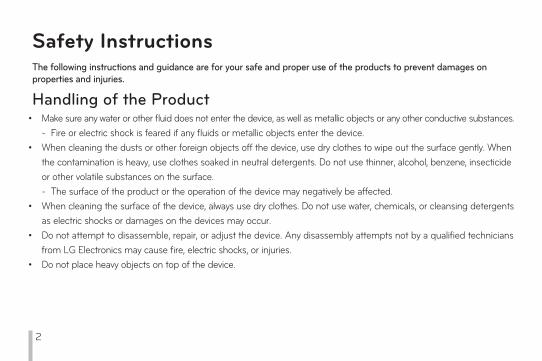
The following instructions and guidance are for your safe and proper use of the products to prevent damages on properties and injuries.
Handling of the Product•
•
•
•
•
Make sure any water or other fluid does not enter the device, as well as metallic objects or any other conductive substances. - Fire or electric shock is feared if any fluids or metallic objects enter the device. When cleaning the dusts or other foreign objects off the device, use dry clothes to wipe out the surface gently. When the contamination is heavy, use clothes soaked in neutral detergents. Do not use thinner, alcohol, benzene, insecticide or other volatile substances on the surface.- The surface of the product or the operation of the device may negatively be affected.When cleaning the surface of the device, always use dry clothes. Do not use water, chemicals, or cleansing detergents as electric shocks or damages on the devices may occur.Do not attempt to disassemble, repair, or adjust the device. Any disassembly attempts not by a qualified technicians from LG Electronics may cause fire, electric shocks, or injuries.Do not place heavy objects on top of the device.
Safety Instructions
2
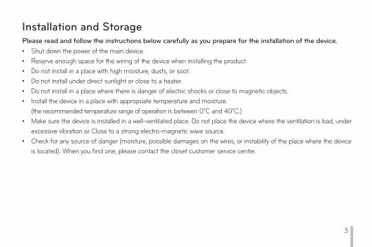
Installation and StoragePlease read and follow the instructions below carefully as you prepare for the installation of the device.••••••
•
•
Shut down the power of the main device.Reserve enough space for the wiring of the device when installing the product.Do not install in a place with high moisture, dusts, or soot.Do not install under direct sunlight or close to a heater.Do not install in a place where there is danger of electric shocks or close to magnetic objects.Install the device in a place with appropriate temperature and moisture.(the recommended temperature range of operation is between 0°C and 40°C.)Make sure the device is installed in a well-ventilated place. Do not place the device where the ventilation is bad, under excessive vibration or Close to a strong electro-magnetic wave source.Check for any source of danger (moisture, possible damages on the wires, or instability of the place where the device is located). When you find one, please contact the closet customer service center.
3
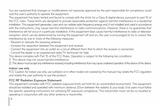
You are cautioned that changes or modifications not expressly approved by the part responsible for compliance could void the user’s authority to operate the equipment.This equipment has been tested and found to comply with the limits for a Class B digital device, pursuant to part 15 of the FCC rules. These limits are designed to provide reasonable protection against harmful interference in a residential installation. This equipment generates, uses and can radiate radio frequency energy and, if not installed and used in accordance with the instructions, may cause harmful interference to radio communications. However, there is no guarantee that interference will not occur in a particular installation. If this equipment does cause harmful interference to radio or television reception, which can be determined by turning the equipment off and on, the user is encouraged to try to correct the interference by one or more of the following measures:- Reorient or relocate the receiving antenna.- Increase the separation between the equipment and receiver.- Connect the equipment into an outlet on a circuit different from that to which the receiver is connected.- Consult the dealer or an experienced radio/TV technician for help.This device complies with Part 15 of the FCC Rules. Operation is subject to the following two conditions:1) This device may not cause harmful interference. 2) This device must accept any interference received, including interference that may cause undesired operation of the device of the device.
Indoor use onlyFCC Caution: for indoor use only, use outdoors or in other modes not covered by this manual may violate the FCC regulation and violate the user authority to use the product.
FCC RF Radiation Exposure Statement:This equipment complies with FCC radiation exposure limits set forth for an uncontrolled environment. This equipment should be installed and operated with minimum distance 20cm between the radiator & your body. End users must follow the specific operating instructions for satisfying RF exposure compliance. This transmitter must not be co-located or operating in conjunction with any other antenna or transmitter. 4
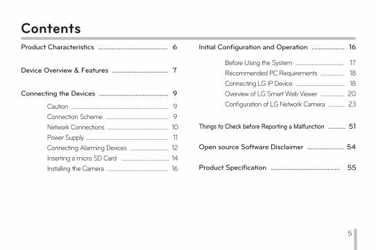
Product Characteristics ........................................ 6
Device Overview & Features ................................ 7
Connecting the Devices ........................................ 9
Caution ............................................................................. 9Connection Scheme ................................................. 9Network Connections ................................................Power Supply ..................................................................
10
Connecting Alarming Devices .............................. 1211
Inserting a micro SD Card ...................................... 14Installing the Camera ................................................ 16
Initial Configuration and Operation ................... 16
Before Using the System ...................................... 17Recommended PC Requirements ................... 18Connecting LG IP Device ....................................... 18Overview of LG Smart Web Viewer ................... 20Configuration of LG Network Camera ............. 23
Things to Check before Reporting a Malfunction .......... 51
Open source Software Disclaimer ..................... 54
Product Specification ........................................ 55
Contents
5

Product Characteristics
••••••
••••
Multi Codec Streaming (H.264, MJPEG)Audio supported (G.711/G.726 Full Duplex)Ethernet 100MbpsWireless Lan802.11b/g/nDigital Input/Output: Input 1port, Output 1portExntended memory using a micro SD card(up to 32GB)Pre/Post Alarming feature and recordingHuman Motion DetectionNight Flash LED (5meter radious)AW, AE, Sharpness
Note:A PIR sensor can detect human motions within 5m radius.
PIR Max. Detection Radius
LG Network Camera is a more convenient, easy-to-use network-based surveillance system. As you establish a network based surveillance environment using LG’s Network Cameras, you can easily perform various surveillance tasks such as the video monitoring, recording, configurations and event management.
With this manual, you can learn how to install and operate LG Network Camera in a networked enviroment in details. Any prior knowledge or familiarity with the network environment will be of assistance as you try to understand this manual.
If you need further technical assistance, contact our customer service centers.
6
Device Overview & Features
7
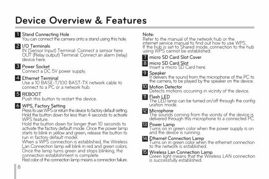
Device Overview & FeaturesNote: Refer to the manual of the network hub or the internet service manual to find out how to use WPS.If the hub is set to Shared mode, connection to the hub using WPS cannot be established.
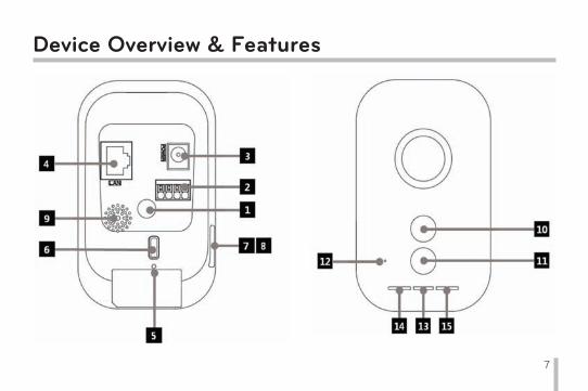
Stand Connecting HoleYou can connect the camera onto a stand using this hole.I/O TerminalsIN (Sensor Input) Terminal: Connect a sensor here.OUT (Relay output) Terminal: Connect an alarm (relay) device here.Power SocketConnect a DC 5V power supply.Ethernet TerminalUse a 10 BASE-T/100 BAST-TX network cable to connect to a PC or a network hub.REBOOTPush this button to restart the device.WPS, Factory SettingPress to use WPS or return the device to factory default setting.Hold the button down for less than 4 seconds to activate WPS feature. Hold the button down for longer than 10 seconds to activate the factory default mode. Once the power lamp starts to blink in yellow and green, release the button to run in factory default model.When a WPS connection is established, the Wireless Lan Connection lamp will blink in red and green colors. Once the lamp turns green and stops blinking, the connection establishment is complete.Red color of the connection lamp means a connection failure.
1
2
3
4
5
6
micro SD Card Slot Covermicro SD Card SlotInsert a micro SD Card here.SpeakerIt delivers the sound from the microphone of the PC to the camera, to be played by the speaker on the device.Motion DetectorDetects motions occurring in vicinity of the device.Flash LEDThe LED lamp can be turned on/off through the configuration mode.MicrophoneThe sounds coming from the vicinity of the device is delivered through this microphone to a connected PC.Power LampTurns on in green color when the power supply is on and the device is running.Ethernet Connection LampTurns on in green color when the ethernet connection to the network is established.Wireless Lan Connection LampGreen light means that the Wireless LAN connection is successfully established.
78
9
10
11
12
13
14
15
8
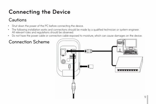
Cautions• Shut down the power of the PC before connecting the device.• The following installation works and connections should be made by a qualified technician or system engineer.
All relevant rules and regulations should be observed.• Do not have the power cable or connection cable exposed to moisture, which can cause damages on the device.
Connection Scheme
Connecting the Device
9
Network Connections
Connecting the Device
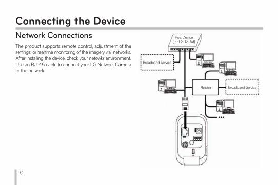
The product supports remote control, adjustment of the settings, or realtime monitoring of the imagery via networks.After installing the device, check your netowkr environment.Use an RJ-45 cable to connect your LG Network Camera to the network.
PoE Device(IEEE802.3af)
Broadband Service
Broadband ServiceRouter
10
10
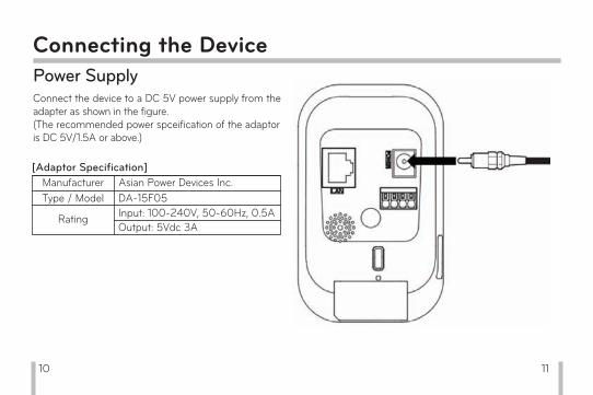
Power SupplyConnect the device to a DC 5V power supply from the adapter as shown in the figure.(The recommended power spceification of the adaptor is DC 5V/1.5A or above.)
Connecting the Device
ManufacturerType / Model
Asian Power Devices Inc.DA-15F05Input: 100-240V, 50-60Hz, 0.5AOutput: 5Vdc 3A
Rating
[Adaptor Specification]
11
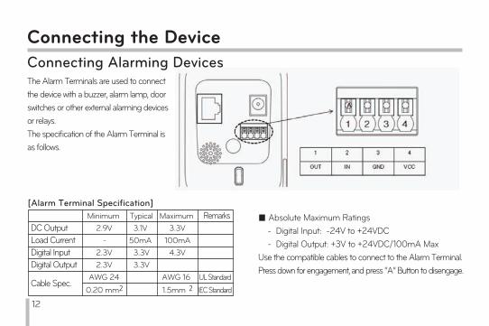
Connecting the DeviceConnecting Alarming DevicesThe Alarm Terminals are used to connect the device with a buzzer, alarm lamp, door switches or other external alarming devices or relays. The specification of the Alarm Terminal is as follows.
■ Absolute Maximum Ratings - Digital Input: -24V to +24VDC - Digital Output: +3V to +24VDC/100mA MaxUse the compatible cables to connect to the Alarm Terminal. Press down for engagement, and press “A” Button to disengage.
[Alarm Terminal Specification]Minimum Typical Maximum Remarks
Digital Input 2.3V 3.3V 4.3VDigital Output 2.3V 3.3V
Cable Spec.AWG 24 AWG 16 UL Standard
0.20 mm2 1.5mm 2 IEC Standard
Load Current - 50mA 100mADC Output 2.9V 3.1V 3.3V
12

Sensor
Alarm (Relay) Device
IN (Sesor Input)Connect a Sensor to the Sensor Input Terminal.
Output (Relay Output)Connect an alarming device (or a relay) to the Relay Output Terminal of the device. Alarming signals will be given in case of an event.
Connecting the Device
Note:For a Photo MOS relay, use regular voltages of AC28V, 100mA or DC20V, 100mA.
13

Connecting the DeviceInserting a micro SD CardYou can use a micro SD card to prevent interruption of recording or monitoring even when there is a network failure.
Inserting a micro SD Card1. Open the micro SD Card Slot Cover.2. As illustrated below, insert the micro SD card while making sure the direction of the terminals on the card is properly aligned. Slide in the card slowly, and give a little pressure at the end to complete the insertion of the card.
Note:Do not use excessive force as you slide in the card to prevent damages.Inserting the card with the terminals facing the wrong dirction may result in the damages of the card of the card slot on the device.Keep the metallic terminal on the card clear of any foreign objects or contamination.The SD card is a consumable item. After a certain number of reading/writing operations the card may expire and the data may not be saved. In this case, replace the expired card with a new one.14
Connecting the Device
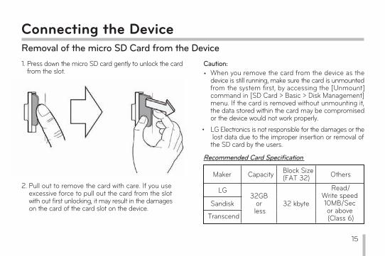
1. Press down the micro SD card gently to unlock the card from the slot.
2. Pull out to remove the card with care. If you use excessive force to pull out the card from the slot with out first unlocking, it may result in the damages on the card of the card slot on the device.
Removal of the micro SD Card from the Device
When you remove the card from the device as the device is still running, make sure the card is unmounted from the system first, by accessing the [Unmount] command in [SD Card > Basic > Disk Management] menu. If the card is removed without unmounting it, the data stored within the card may be compromised or the device would not work properly.LG Electronics is not responsible for the damages or the lost data due to the improper insertion or removal of the SD card by the users.
Caution:•
•
Recommended Card Specification
Maker Capacity Block Size (FAT 32) Others
LG32GB
or less
32 kbyte
Read/Write speed 10MB/Sec or above (Class 6)
Sandisk
Transcend
15

Connecting the DeviceInstalling the CameraEnsure the camera is placed on a safe and stable position where the weight of the camera can securely be supported sustainably.1. Disconnect the stand from the body. - Turn the nut-cover counterclockwise to remove the cover from the body.
2. Fix the stand. - Detach the stand cover and fix the stand using two screws provided with it.
3. Attach the body of the device on the fixed stand. - Engage the stand with the body of the device and turn the nut- cover clockwise to fix it.
When redirecting your camera, turn the nut cover to the left to loosen the stand from the body first before you turn the camera for a new direction. LG Electronics is not responsible for any damages on the camera due to attempts to redirect it while the fixtures are not loosened.
Caution:
16
Before Using the System•
•
•
Before you use LG IP device, check the connection cables and power supply of the device.
Make sure LG IP device is connected to the network and each of the system components are powered up.
To connect to a PC, you need to install LG Client software on the machine first. Once you connect the PC with an LG IP device, the Smart Web Viewer Software automatically starts the installation procedure.LG IPSOLUTE and LG Smart Web Viewer software are the network software that is used in controlling the LG Network Video Server and LG IP Cameras.
Initial Configuration and Operation
•
•
•
To view the video stream on a web browser, you first need to allow the installation of the Active X controls in the settings menu of your web browser. Once you see the installation warning message of ‘IPCam_Streamer.cab distributed by LG ELECTRONICS.IN,’ click on the yellow bar on the upper margin of your web browser’s screen to install LG Smart Web Viewer Software (which is an Active X control.)
The images displayed on your screen may differ in accordance with the different types of OS or web browser you use.
Do not run the client program with other software, which may cause errors or excessive memory consumption.
17
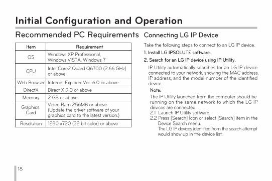
Initial Configuration and OperationRecommended PC Requirements
Item Requirement
OS Windows XP Professional, Windows VISTA, Windows 7
CPU Intel Core2 Quard Q6700 (2.66 GHz)or above
Web Browser Internet Explorer Ver. 6.0 or aboveDirectX Direct X 9.0 or aboveMemory 2 GB or above
Graphics Card
Video Ram 256MB or above (Update the driver software of your graphics card to the latest version.)
Resolution 1280 x720 (32 bit color) or above
Connecting LG IP DeviceTake the following steps to connect to an LG IP device.1. Install LG IPSOLUTE software.2. Search for an LG IP device using IP Utility.
IP Utility automatically searches for an LG IP device connected to your network, showing the MAC address, IP address, and the model number of the identified device. Note:The IP Utility launched from the computer should be running on the same network to which the LG IP devices are connected.2.1 Launch IP Utility software.2.2 Press [Search] Icon or select [Search] item in the Device Search menu. The LG IP devices identified from the search attempt would show up in the device list.
18
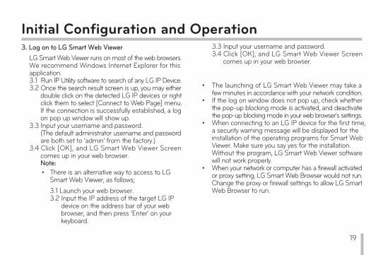
Initial Configuration and Operation3. Log on to LG Smart Web Viewer
LG Smart Web Viewer runs on most of the web browsers. We recommend Windows Internet Explorer for this application. 3.1 Run IP Utility software to search of any LG IP Device.3.2 Once the search result screen is up, you may either double click on the detected LG IP devices or right click them to select [Connect to Web Page] menu. If the connection is successfully established, a log on pop up window will show up.3.3 Input your username and password. (The default administrator username and password are both set to ‘admin’ from the factory.)3.4 Click [OK], and LG Smart Web Viewer Screen comes up in your web browser.
Note:• There is an alternative way to access to LG
Smart Web Viewer, as follows;3.1 Launch your web browser.3.2 Input the IP address of the target LG IP device on the address bar of your web browser, and then press ‘Enter’ on your keyboard.
•
•
•
•
The launching of LG Smart Web Viewer may take a few minutes in accordance with your network condition. If the log on window does not pop up, check whether the pop-up blocking mode is activated, and deactivate the pop-up blocking mode in your web browser’s settings. When connecting to an LG IP device for the first time, a security warning message will be displayed for the installation of the operating programs for Smart Web Viewer. Make sure you say yes for the installation. Without the program, LG Smart Web Viewer software will not work properly. When your network or computer has a firewall activated or proxy setting, LG Smart Web Browser would not run. Change the proxy or firewall settings to allow LG Smart Web Browser to run.
3.3 Input your username and password.3.4 Click [OK], and LG Smart Web Viewer Screen comes up in your web browser.
19

Initial Configuration and OperationOverview of LG Smart Web Viewer
20
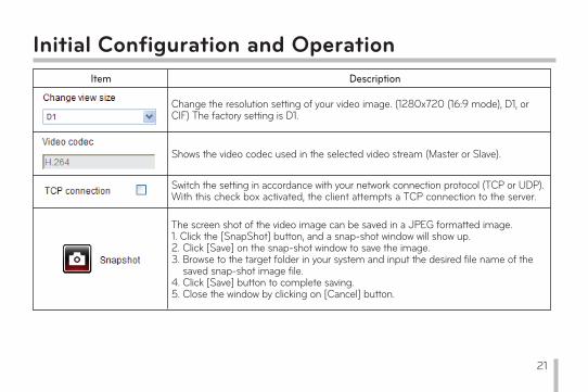
Initial Configuration and OperationItem Description
Change the resolution setting of your video image. (1280x720 (16:9 mode), D1, or CIF) The factory setting is D1.
Shows the video codec used in the selected video stream (Master or Slave).
Switch the setting in accordance with your network connection protocol (TCP or UDP). With this check box activated, the client attempts a TCP connection to the server.
The screen shot of the video image can be saved in a JPEG formatted image. 1. Click the [SnapShot] button, and a snap-shot window will show up.2. Click [Save] on the snap-shot window to save the image. 3. Browse to the target folder in your system and input the desired file name of the saved snap-shot image file. 4. Click [Save] button to complete saving.5. Close the window by clicking on [Cancel] button.
21
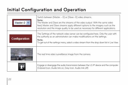
Initial Configuration and OperationSwitch between [Master – 0] or [Slave -0] video streams.Note:The Master and Slave are the streams of the video output. With the same video feed, Master and Slave streams apply different options to the imagery such as the resolution and the image quality to be used as necessary for different applications.
The Settings of the network video server can be configured here. Only the user with the authority as an administrator can make modifications on the settings. Note:To get out of the settings menu, select a video stream from the drop down list in Live View.
The real time video surveillance image from the camera.
Engage or disengage the audio transmission between the LG IP device and the computer.(Colored Icon: Audio link on, Grey Icon: Audio link off)
22
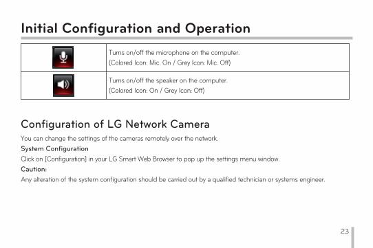
Initial Configuration and OperationTurns on/off the microphone on the computer. (Colored Icon: Mic. On / Grey Icon: Mic. Off)
Turns on/off the speaker on the computer.(Colored Icon: On / Grey Icon: Off)
Configuration of LG Network CameraYou can change the settings of the cameras remotely over the network. System ConfigurationClick on [Configuration] in your LG Smart Web Browser to pop up the settings menu window. Caution:Any alteration of the system configuration should be carried out by a qualified technician or systems engineer.
23

Initial Configuration and OperationOverview of the Systems Configuration Menu
Menu Sub-menus
System
VersionDate & TimeMaintenance
Log & Report Language
Audio & Video
CameraStreamAudio
Motion detect
Network
BasicRTP stream
TCP/IPDDNS
IP filteringWireless
User BasicSD Card Basic
EventEvent Schedule
Event ServerSensor & Relay
24
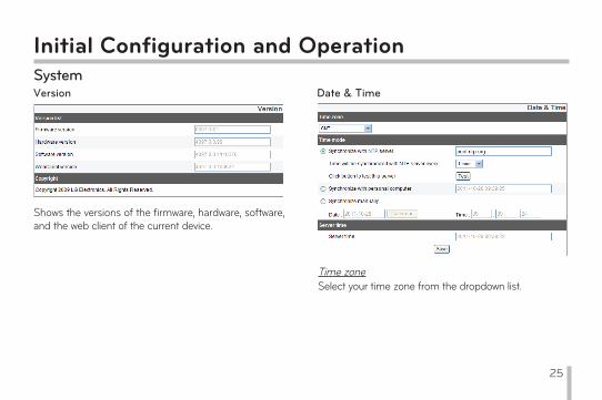
Initial Configuration and OperationSystemVersion
Shows the versions of the firmware, hardware, software, and the web client of the current device.
Date & Time
Time zoneSelect your time zone from the dropdown list.
25

Initial Configuration and OperationTime mode>
>
>
Synchronize with NTP Server: Sets the time of the system according to the Sync. Interval configuration of your system. Input the IP address or the URL of the NTP server and select the interval of the synchronization with it. You can also test the NTP server you set by pressing the [Test] button.Synchronize with personal computer: Synchronize with the clock of your local system to configure the time and date. Synchronize manually: Input the time and date of the system manually.
Note:• Rebooting the system after setting the time may cause
the system clock lag. To maintain precise time, we recommend you select [Synchronize with NTP server] mode.
• If you are using the recording server both for the recording and as an NTP server, refer to the NTP configuration instructions for the OS of the recording server.
Server time> Server time: Displays the current date and time of the
IP device.
• Save: Click [Save] button to save the changes you made in this menu.
26
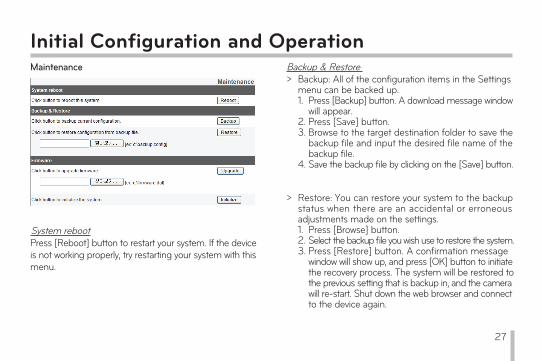
Initial Configuration and OperationMaintenance
System rebootPress [Reboot] button to restart your system. If the device is not working properly, try restarting your system with this menu.
Backup & Restore> Backup: All of the configuration items in the Settings
menu can be backed up. 1. Press [Backup] button. A download message window will appear. 2. Press [Save] button.3. Browse to the target destination folder to save the backup file and input the desired file name of the backup file. 4. Save the backup file by clicking on the [Save] button.
> Restore: You can restore your system to the backup status when there are an accidental or erroneous adjustments made on the settings. 1. Press [Browse] button. 2. Select the backup file you wish use to restore the system.3. Press [Restore] button. A confirmation message window will show up, and press [OK] button to initiate the recovery process. The system will be restored to the previous setting that is backup in, and the camera will re-start. Shut down the web browser and connect to the device again.
27
Initial Configuration and OperationNote:•
•
The backup and recovery functionalities can only work when the system that you will apply the backup file has the same firmware version. These functionalities cannot be used for multi-layered environment or a firmware upgrade.
Backup is only possible under HTTP protocol. HTTPS protocol does not support backup functionality.
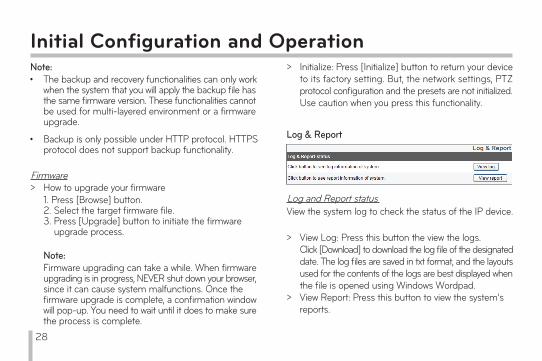
Firmware> How to upgrade your firmware
1. Press [Browse] button. 2. Select the target firmware file. 3. Press [Upgrade] button to initiate the firmware upgrade process.
Note:Firmware upgrading can take a while. When firmware upgrading is in progress, NEVER shut down your browser, since it can cause system malfunctions. Once the firmware upgrade is complete, a confirmation window will pop-up. You need to wait until it does to make sure the process is complete.
> Initialize: Press [Initialize] button to return your device to its factory setting. But, the network settings, PTZ protocol configuration and the presets are not initialized. Use caution when you press this functionality.
Log & Report
Log and Report statusView the system log to check the status of the IP device.
>
>
View Log: Press this button the view the logs.Click [Download] to download the log file of the designated date. The log files are saved in txt format, and the layouts used for the contents of the logs are best displayed when the file is opened using Windows Wordpad. View Report: Press this button to view the system’s reports.
28
Save: Press this buttons to save the changes you made.
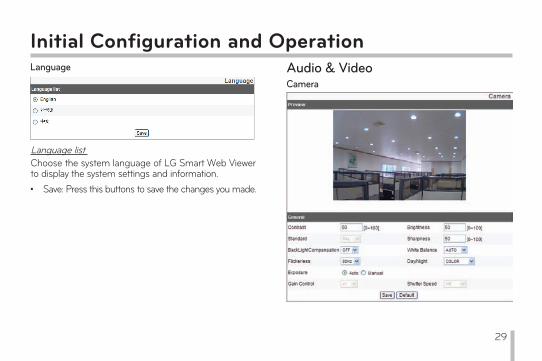
Initial Configuration and OperationLanguage
Language listChoose the system language of LG Smart Web Viewer to display the system settings and information. •
Audio & VideoCamera
29
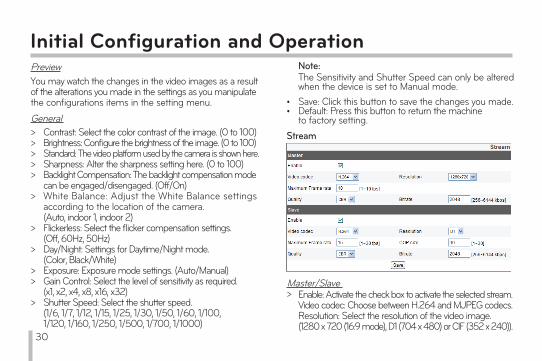
PreviewYou may watch the changes in the video images as a result of the alterations you made in the settings as you manipulate the configurations items in the setting menu.
Initial Configuration and Operation
General>>>>>
>
>
>
>>
>
Contrast: Select the color contrast of the image. (0 to 100)Brightness: Configure the brightness of the image. (0 to 100)Standard: The video platform used by the camera is shown here. Sharpness: Alter the sharpness setting here. (0 to 100)Backlight Compensation: The backlight compensation mode can be engaged/disengaged. (Off/On)White Balance: Adjust the White Balance settings according to the location of the camera. (Auto, indoor 1, indoor 2)Flickerless: Select the flicker compensation settings. (Off, 60Hz, 50Hz)Day/Night: Settings for Daytime/Night mode. (Color, Black/White)Exposure: Exposure mode settings. (Auto/Manual)Gain Control: Select the level of sensitivity as required. (x1, x2, x4, x8, x16, x32)Shutter Speed: Select the shutter speed.(1/6, 1/7, 1/12, 1/15, 1/25, 1/30, 1/50, 1/60, 1/100, 1/120, 1/160, 1/250, 1/500, 1/700, 1/1000)
••
Save: Click this button to save the changes you made. Default: Press this button to return the machine to factory setting.
>Master/Slave
Enable: Activate the check box to activate the selected stream.Video codec: Choose between H.264 and MJPEG codecs. Resolution: Select the resolution of the video image.(1280 x 720 (16:9 mode), D1 (704 x 480) or CIF (352 x 240)).
Stream
Note:The Sensitivity and Shutter Speed can only be altered when the device is set to Manual mode.
30
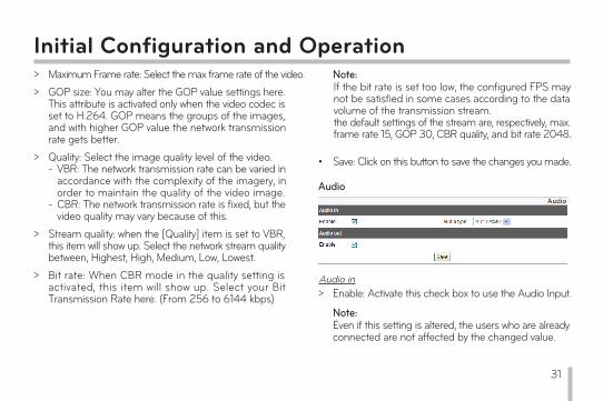
Maximum Frame rate: Select the max frame rate of the video.GOP size: You may alter the GOP value settings here. This attribute is activated only when the video codec is set to H.264. GOP means the groups of the images, and with higher GOP value the network transmission rate gets better. Quality: Select the image quality level of the video. VBR: The network transmission rate can be varied in accordance with the complexity of the imagery, in order to maintain the quality of the video image. CBR: The network transmission rate is fixed, but the video quality may vary because of this. Stream quality: when the [Quality] item is set to VBR, this item will show up. Select the network stream quality between, Highest, High, Medium, Low, Lowest.Bit rate: When CBR mode in the quality setting is activated, this item will show up. Select your Bit Transmission Rate here. (From 256 to 6144 kbps)
Initial Configuration and Operation>>
>
>
>
-
-
Note:If the bit rate is set too low, the configured FPS may not be satisfied in some cases according to the data volume of the transmission stream. the default settings of the stream are, respectively, max. frame rate 15, GOP 30, CBR quality, and bit rate 2048.
• Save: Click on this button to save the changes you made.
Audio
Audio in> Enable: Activate this check box to use the Audio Input.
Note:Even if this setting is altered, the users who are already connected are not affected by the changed value.
31
Initial Configuration and Operation> Audio type: Choose the type of audio encoding that
you wish to use. (G.711 PCMA, G.711 PCMU, G.726 24K, G.726 32K)
Audio out>
•
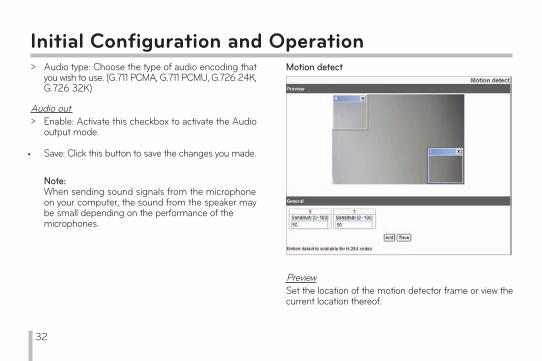
Motion detect
PreviewSet the location of the motion detector frame or view the current location thereof.
Note:When sending sound signals from the microphone on your computer, the sound from the speaker may be small depending on the performance of the microphones.
Enable: Activate this checkbox to activate the Audio output mode.
Save: Click this button to save the changes you made.
32
Initial Configuration and OperationGeneral>
>
Sensitivity: Set the sensitivity of the motion detector to detect any moving objects in the scene. At high sensitivity, even tiny twitches in the scene can be detected as a moving object. Save: Click this button to save the changes you made.
Setting the motion detector frame1. Click [Add] button to add a motion detector frame on screen. As you click the button, newly added motion detector frame will appear on the preview screen, and you may add upto five frames per scene. 2. Set the sensitivity value for the frame at [Sensitivity] menu.3. Click on the motion detector frame at its rim or sides and drag to a desired position.4. Click [Save] to save the changes. Note:•
•
The size of the motion detector frame can be adjusted. Click on the edge of the frame and drag to adjust the size as necessary. To activate the motion detection functionality, either of the Master or Slave setting should be activated by activating the [Enable] Item. Also the video codec should be set at H.264 and the value of GOP should be 2 or higher to allow the motion detection mode to function.
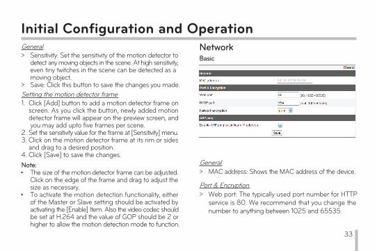
NetworkBasic
General> MAC address: Shows the MAC address of the device.
Port & Encryption> Web port: The typically used port number for HTTP
service is 80. We recommend that you change the number to anything between 1025 and 65535.
33
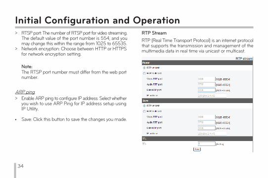
Initial Configuration and Operation>
>
RTSP port: The number of RTSP port for video streaming. The default value of the port number is 554, and you may change this within the range from 1025 to 65535.Network encryption: Choose between HTTP or HTTPS for network encryption setting.
Note:The RTSP port number must differ from the web port number.
ARP ping> Enable ARP ping to configure IP address: Select whether
you wish to use ARP Ping for IP address setup using IP Utility.
Save: Click this button to save the changes you made. •
RTP StreamRTP (Real Time Transport Protocol) is an internet protocol that supports the transmission and management of the multimedia data in real time via unicast or multicast.
34
Initial Configuration and OperationMaster / Slave>
>
RTP Unicast: Check this radio button when you are using RTP unicast.RTP Multicast: Check this radio button when you are using RTP multicast.
-
-
-
-
Video RTP port: Set the number of Video RTP port. The range of the possible port number is from 1,025 to 65,534.
Audio RTP port: Set the number of Audio RTP port. The range of the possible port number is from 1,025 to 65,534.
Data RTP port: Set the number of Data RTP port. The range of the possible port number is from 1,025 to 65,534.
IP address: Set the IP address for RTP multicast. The range of the possible address is from 240.0.0.0 to 239.255.255.255.
Note:When using multicast, avoid using the same port number with the multicast to prevent the video stream from overwrapping. Also, use unique IP addresses and port number for each device, or there might be IP address collision between the devices.
TTL> TTL: Set the TTL(Time To Live) value. The default setting
is 7, and the possible range of the value is from 1 to 225.
• Save: Press this button to save any changes you made.
35

Initial Configuration and OperationTCP/IP
IP Address status> Automatically set with DHCP: Click on this radio button
if you wish to use DHCP mode. The network settings are automatically configured by the DHCP server.
- Notify to SMTP server, if IP address is changed: With this option activated, the system will notify the user with the new IP address each time it changes by sending an e-mail.
Note:To use this functionality, the mail server should be registered within the event server configuration.
> Statically set: Manually configure the network settings.IP address: Input the IP address here.Subnet mask: Input the subnet mask address here.Gateway: Input the gateway address here.
---
DNS Server status>
>
Primary DNS Server: Input the main DNS server address here.A DNS (Domain Name Service) changes the domain name into an IP address within the network. Secondary DNS Server: Input the address of the Secondary DNS Server.
• Save: Click this button to save the changes you made.
36
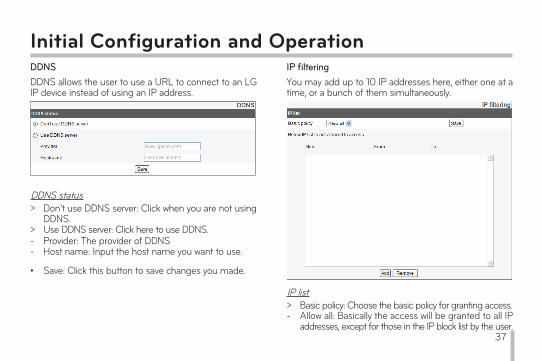
Initial Configuration and OperationDDNSDDNS allows the user to use a URL to connect to an LG IP device instead of using an IP address.
DDNS status>
>
Don’t use DDNS server: Click when you are not using DDNS.Use DDNS server: Click here to use DDNS.
--
Provider: The provider of DDNSHost name: Input the host name you want to use.
• Save: Click this button to save changes you made.
IP filteringYou may add up to 10 IP addresses here, either one at a time, or a bunch of them simultaneously.
IP list> Basic policy: Choose the basic policy for granting access.- Allow all: Basically the access will be granted to all IP
addresses, except for those in the IP block list by the user. 37
- Alias: Input the name here.From: Insert the beginning address from which the access control policy applies.To: Insert the address at the end of the application range of the access control policy.
Initial Configuration and Operation- Deny all: Basically the access will not be granted to any
IP address except for those listed in the Access Permission List. To active this mode, there should be at least one or more address registered in the list.
•
•
Save: Click here to save the change you made for the setting.
Add: Add an IP address to the list.1. Press [Add] button.2. Input the following items on the list.
Note:To apply your access granting policy (either blocking or opening for them) to a range of addresses, insert the starting address of the range as the Beginning Address and the last one as the End Address. If you wish to add only one address, input the same address both for the Beginning and End addresses.
3. Click [Save] button.4. Repeat step 1 to step 3 to add more IP addresses.
• Remove: Deletes one or more addresses from the list.1. Select the address you wish to delete from the list.2. Click [Remove] button to eliminate it (or them) from the list.
38
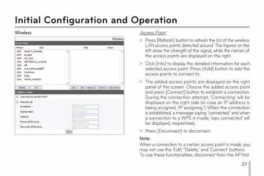
Initial Configuration and OperationWireless Access Point
>
>
>
>
Press [Refresh] button to refresh the list of the wireless LAN access points detected around. The figures on the left show the strength of the signal, while the names of the access points are displayed on the right.Click [Info] to display the detailed information for each selected access point. Press [Add] button to add the access points to connect to.The added access points are displayed on the right panel of the screen. Choose the added access point and press [Connect] button to establish a connection. During the connection attempt, ‘Connecting’ will be displayed on the right side (in case an IP address is being assigned, ‘IP assigning.’) When the connection is established, a message saying ‘connected,’ and when a connection to a WPS is made, ‘wps connected’ will be displayed, respectively.Press [Disconnect] to disconnect.
Note:When a connection to a certain access point is made, you may not use the ‘Edit,’ ‘Delete,’ and ‘Connect’ buttons.To use these functionalities, disconnect from the AP first.
39

Initial Configuration and Operation>
>
>
You may use an access point you would like to use by pressing [Add] button to add a new access point.
To change the information on the added access point, press [Edit] to change.
To delete an added access point, select the target access point and press [Remove].
IP Address status>
>
Automatically set with DHCP: Click on this radio button to use DHCP to automatically configure the network settings of the device through a DHCP server.Statically set: Manually set the network configurations.----
-
IP address: Input the IP address.Subnet mask: Input the subnet mask address.Gateway: Input the gateway address.Primary DNS server: Input the address of the Main DNS Server.Secondary DNS server: Input the address of the secondary DNS server.
Save: Press this button to save the changes you made.
Note:Due to the nature of a Wi-Fi network, signal interruption may be feared at 2.4GHz when the device is connected through a wireless LAN network. Depending on the number of the wireless devices that are sharing the hub to which the camera is connected or the hubs using the same or adjacent channels, the network speed might become slower. As there are possibilities of the video feed being interrupted due to the network problem when used under a wireless network environment, it is recommended that the stream settings of the audio and video are set to default settings.
•
40
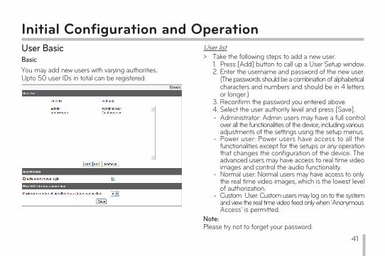
Initial Configuration and OperationUser BasicBasicYou may add new users with varying authorities.Upto 50 user IDs in total can be registered.
User list> Take the following steps to add a new user.
1. Press [Add] button to call up a User Setup window.2. Enter the username and password of the new user. (The passwords should be a combination of alphabetical characters and numbers and should be in 4 letters or longer.)3. Reconfirm the password you entered above.4. Select the user authority level and press [Save].-
-
-
-
Administrator: Admin users may have a full control over all the functionalities of the device, including various adjustments of the settings using the setup menus.Power user: Power users have access to all the functionalities except for the setups or any operation that changes the configuration of the device. The advanced users may have access to real time video images and control the audio functionality.Normal user: Normal users may have access to only the real time video images, which is the lowest level of authorization.Custom User: Custom users may log on to the system and view the real time video feed only when ‘Anonymous Access’ is permitted.
Note:Please try not to forget your password.
41
Initial Configuration and Operation>
>
Editing a registered userThe password or the authorization setting of an existing user may be altered.1. Select the target user for alteration and press [Edit].2. Make changes to the password or the authorities as necessary and press [Save] to save the changes made.
Deleting a registered user1. Choose the user to be deleted.2. Press [Remove] button and the selected user will be removed.
Note:You cannot delete the ‘admin’ user and ‘anonymous’ user, which is the temporary user account.
Anonymous> Enable anonymous login
Activate the checkbox to allow anonymous access to the system. An anonymous user may have access only to the real time video stream.
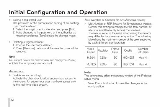
Max. Number of Streams for Simultaneous Access> Max.Number of RTP Streams for Simultaneous Access
Control this setting to manipulate the total number of users to simultaneously access the streams.The max. number of the users for accessing the streams may differ by the stream configuration. The following table shows the maximum number of the users supported by each different configuration.
Video Codec Resolution Frame
Rate Quality Number of Users
H.264 720p 30 HIGHEST Max. 4
MJPEG 720p 20 HIGHEST Max. 4
Note:This setting may affect the preview window of the IP device setup menu.• Save: Press this button to save the changes in the
configuration.
42

Initial Configuration and OperationSD Card SettingsBasic
SD Card Recording>>
Always: Starts recording to SD cards immediately.Recurrence pattern: Automatically repeats recording to SD cards at designated time and days of the week set by the user.
Note:It is not possible to set different times for different days of weeks. The recording starts automatically at designated time on the designated days of the week.
>
>
>
Never: Do not use [Always] and [Recurrence Pattern] recording functions.Overwrite: When the memory in the card left is not sufficient, the images recorded are overwritten, with the oldest one in the card first.DiskFull Notification: If the ‘Overwrite’ menu is not activated and the remaining memory space in the card comes below a certain level, the event server sends a warning e-mail to a designated e-mail address.
43
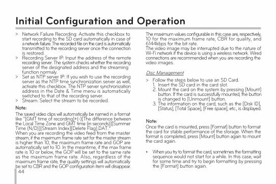
Initial Configuration and Operation>
>
>
>
Network Failure Recording: Activate this checkbox to start recording to the SD card automatically in case of a network failure. The recorded file on the card is automatically transmitted to the recording server once the connection is restored. Recording Server IP: Input the address of the remote recording server. The system checks whether the recording server of the designated address and the streaming function normaly.Set as NTP server IP: If you wish to use the recording server as the NTP time synchronization server as well, activate this checkbox. The NTP server synchronization address in the Date & Time menu is automatically switched to that of the recording server.Stream: Select the stream to be recorded.
Note:The saved video clips will automatically be named in a format like “[GMT time of recording]+(-)[The difference between the Local Time Zone and GMT time (in seconds)][Summer Time (N/D)][Stream Index][Delete Flag].DAT.”When you are recording the video feed from the master stream, if the maximum frame rate set for the master stream is higher than 10, the maximum frame rate and GOP are automatically set to 10. In the meantime, if the max frame rate is 10 or below, the GOP will be set to the same rateas the maximum frame rate. Also, regardless of the maximum frame rate, the quality settings will automaticallybe set to CBR and the GOP configuration item will disappear.
Disc Management> Follow the steps below to use an SD Card.
1. Insert the SD card in the card slot.2. Mount the card on the system by pressing [Mount] button. If the card is successfully mounted, the button is changed to [Unmount] button.3. The information on the card, such as the [Disk ID], [Status], [Total Space], [Free space], etc., is displayed.
Note:Once the card is mounted, press [Format] button to format the card for stable performance of the storage. When the format is completed, press [Mount] button again to mount the card again.
The maximum values configurable in this case are, respectively, 10 for the maximum frame rate, CBR for quality, and 6144kbps for the bit rate.The video image may be interrupted due to the nature of Wi-Fi network if the device is using a wireless network. Wired connections are recommended when you are recording the video images.
• When you try to format the card, sometimes the formatting sequence would not start for a while. In this case, wait for some time and try to begin formatting by pressing the [Format] button again.
44

Initial Configuration and Operation> To remove the card from the system;
1. Press [Unmount] button to unmount the card from the system. Once the unmounting is completed, the [Mount] button will appear.2. Pull out the card from the socket.
Note:When you attempt to unmount a card, sometimes the unmounting sequence would not start. This is because the system is still writing or reading data on the card as you attempt the unmounting.
File ManagementDisplay a list of files that are stored in the SD Card.To check the files recorded on the card, press [Search] button. The list of the files are only updated when this button is pressed.
Some: Search the files that meet the specified conditions, such as the date and time of recording.2. Press [Search] button to show the search results on the panel.
> Searching for a saved file.1. Select the search condition. All: Display all of the recorded files stored on the card.
>
> Remove: Delete the selected file from the SD card.
-
Download: Select a target file from the list and press [Download] to start downloading. Once you hit this button, two windows will show up. Make sure you download both the video file and the data file.
We recommend that you disengage the Overwrite mode. When the card is nearly full and the Overwrite functionality is activated, the old file you may be download can be overwritten with the download still in progress, which will result in a corrupted file that would not play.The downloaded files can be played using LG IPSOLUTE Player.File corruption may occur if the SD card is using FAT File System.
Note:-
-
-
45
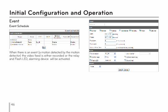
Initial Configuration and OperationEventEvent Schedule
When there is an event (a motion detected by the motion detector) the video feed is either recorded or the relay and Flash LED, alarming device will be activated.
46
Initial Configuration and OperationNote:•
•
•
•
•
In order to activate ‘FTP server / SMTP server’ settings, a file server and/or mail server should be registered at the event server setting sub menu under the event menu.The recorded files of the event (motion detector/sensor event) are split up by a 5 minutes duration. In case the remaining free space in the SD card is 200MB or below, the system stops recording or overwrites an existing file in accordance with the [Overwrite] setting. An overwritten file may cause error or would not play when you try to open the file.Set the video codec to MJPEG, and the video recorded on the SD card will have only one frame per second. When you are recording the master stream video using a FTP Server/SD Card, if the maximum frame rate set for the master stream is higher than 10, the maximum frame rate and GOP are automatically set to 10. In the meantime, if the max frame rate is 10 or below, the GOP will be set to the same rate as the maximum frame rate. Also, regardless of the maximum frame rate, the quality settings will automatically be set to CBR and the GOP configuration item will disappear. The maximum values configurable in this case are, respectively, 10 for the maximum frame rate, CBR for quality, and 6144kbps for the bit rate.
-
--
--
••
•
•
Event Schedule ListEditing the Event Schedule List1. Select an event trigger and press [Edit] button. An event setup window will pop-up.2. Make appropriate changes to the settings. Trigger: The selected trigger event Time: Set the day of the week, the time, pre-alarm duration and Post alarm duration, and the duration of the time during which the inputs will be ignored. Action: Set the actions to be taken as below. FTP Server /SMTP Server: Choose whether to upload the image to an FTP server or send an e-mail to an SMTP server. Control relay: Activate or deactivate a selected relay. SD Card Recording: Record the video feed to the SD card when there is an event. Flash LED: Turns on the Flash LED when there is an event. Sound Alert: Strike up a sound alarm in case of an event. Stream: Choose the desired video feed stream from the relevant camera.3. Press [Save] button to save the changes in settings.
>
47
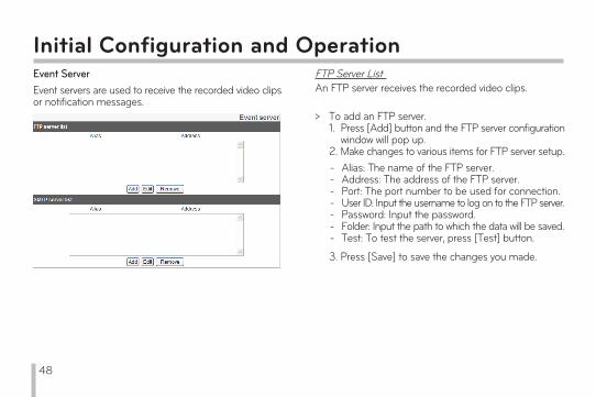
Initial Configuration and OperationEvent ServerEvent servers are used to receive the recorded video clips or notification messages.
FTP Server ListAn FTP server receives the recorded video clips.
> To add an FTP server.1. Press [Add] button and the FTP server configuration window will pop up.2. Make changes to various items for FTP server setup.
3. Press [Save] to save the changes you made.
-------
Alias: The name of the FTP server.Address: The address of the FTP server.Port: The port number to be used for connection.User ID: Input the username to log on to the FTP server.Password: Input the password.Folder: Input the path to which the data will be saved.Test: To test the server, press [Test] button.
48
Initial Configuration and Operation>
>
Editing an FTP server1. Select the target FTP server to be edited from the list.2. Press [Edit] button. Makes changes to setup attributes of the server.
Remove an FTP Server1. Select the target FTP server to be deleted from the list.2. Press [Remove] button.
>
>
Editing SMTP Server1. Select the SMTP server to be edited from the SMTP server list.2. Press [Edit] button. Make necessary changes to the server setup attributes.
Removing an SMTP Server1. Select the SMTP server to be deleted from the list.2. Press [Remove] button.
SMTP Server listAn SMTP server is used to receive notification messages.
> Add an SMTP server.1. Press [Add] button. The SMTP server setup window will appear.2. Make changes to various attributes as below.
-
-
-
---
Enable SSL: Activate this setting when using SSL (Secure Socket Layer) protocol. SSL protocol is an encryption protocol to provide secure communication on the network. Receiving address: Input the e-mail address to be used to receive the notifications.Administrator address: Input the e-mail address of the admin user.Subject: Input title.Message: Input the body text of the notification message.Test: Press [Test] button to test the server.
-----
Alias: Input the name of the SMTP server.User ID: Input the username to log on to the server.Password: Input the password.Address: Input the address of the SMTP server.Port: Input Port number.
3. Press [Save] to save the changes made.
49
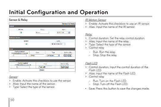
Initial Configuration and OperationSensor & Relay
Sensor>>>
Enable: Activate this checkbox to use the sensor.Alias: Input the name of the sensor.Type: Select the type of the sensor.
IR Motion Sensor>>
Enable: Activate this checkbox to use an IR sensor.Alias: Input the name of the IR sensor.
Relay>>>>
Control duration: Set the relay control duration.Alias: Input the name of the relay.Type: Select the type of the sensor.Control relay--
Run: Run the relay.Stop: Stop the relay.
Flash LED>
>>
Control duration: Input the control duration of the Flash LED.Alias: Input the name of the Flash LED.Control relay--
Run: Turn on the Flash LED.Stop: Turn off the Flash LED.
Save: Press this button to save the changes made.•
50
The following instructions are to help our customers solve some of the operation errors or malfunctions when LG IP devices do not work properly for various reasons.I cannot setup the IP device. • ARP/Ping: Turn of the device and turn the power back
on after waiting for a few minutes. Then it will take another two minutres for the device to be assigned with a new IP address and enter the operation mode. Search for the IP device using IP Utility. Select the relevant IP device from the search result, and right click on the item. From the pop-up menu, find and click [IP Setting by ARP_Ping]. Input your username and password to log on, and then give it the desired IP address. Ping Test: Go to Windows Menu > Start > Run. Type in ‘cmd’ into the command line and click [OK]. Then, you will see the command prompt on the screen. Use ‘Ping’ command to find out the network connection status. Ping Command: Ping IP_device’s IP address. With this command, you may check the following infomraiton.
•
- bytes=32 time=2ms: means the IP address you typed in is working.
-
-
Destination host unreachable: This means the system could not access to a device that is using the IP address you typed in.Request timed out: It means the IP address you gave is simply not in use for the moment.
• Colliding IPs: Collision of IP addresses may happen when you are using a fixed IP address. In case of colliding IPs, shift the IP setting of the colliding device to DHCP and check for the newly assigned IP address through a Ping test or network administrator menus before further use.
I cannot access to my IP device from Smart Web Viewer.• Check the network connection and the power supply
are correctly established or connected. Check if your web browser is set for a proxy. If so, deactivate the proxy mode. Check the URL that is input in the address bar of the web browser, if it starts with ‘HTTPS,’ you may not have an access though HTTP protocol. Shift to Fixed IP mode and check if Subnet mask, Gateway, and DNS server settings are correct.
Things to Check before Reporting a Malfunction
51
Things to Check before Reporting a MalfunctionI want to access a device on the Local network from outside. ••
•
Check your Firewall settings.Check the router configuration. You may require Port Forwarding or DMZ configuration. Contact your network administrator for further guidance regarding the firewalls or the router configuration.
My network is down. •
•
•
In case a heavy traffic occurs over a short period of time, the network may have a problem. Check your network equipments, such as the switch or the hub. Contact your network administrator to find out the cause of the surge in the traffic and make necessary adjustments to the network or remove the cause of such network problems to prevent further network problems.
I lost my log-on password.•
•
Press the Reset button and return the device to the factory setting. Log on to the system using the default admin username and password, and change the user settings as necessary.
I have a problem with the Video Streaming.•
•
•
•
•
When the video is not playing on your web browser, follow the instruction on the screen to install the web client Active X.Deactivate the ‘Pop-up Blocking’ functionality of your web browser before connecting to the system through Smart Web Viewer. Check the settings regarding video streaming in the setup menus (Audio & Video > Stream), and make necessary changes to play the video. If you set the quality or resolution of the video too high, the video may be interrupted or play slow. Select the optimized settings in consideration of the performance of your network. The video may be interrupted or play slow when there is a heavy traffic load on the network. Remove the device that cause such a heavy traffic or make changes to settings to prevent such a surge of the traffic.
52
Things to Check before Reporting a Malfunction•
•
•
The video may be interrupted or play slow when there are a number of other applications running in the client computer. When using LG IPSOLUTE or Smart Web Viewer, try not to use any other software in your computer. If you cannot access to the multicast streaming, check the multicast settings. The IP address and port number should not be the same with any other device. Also, set your router or other network equipment to support multicasting by contacting your network administrator. If you see grey lines in the video, update the driver software of your graphic card to the latest version.
My audio is not working.•
••
•
•
Check if your computer is equipped with a sound card or other sound related components. See if you’re your speakers and microphones are connected properly. See if your sound card supports Full duplex. Check the volume setting of your computer. If the volume is set to ‘Mute,’ deactivate the Mute mode to play sounds. To listen to the audio source from Smart Web Viewer, the Speaker button should be activated. In order to use the bidirectional audio feature, you need to have a microphone connected to your computer and the bidirectional audio button on Smart Web Viewer must be activated.
53
LG Electronics will also provide open source code to you on CD-ROM for a charge covering the cost of performing such distribution (such as the cost of media, shipping and handling) upon email request to [email protected]. This offer is valid for three (3) years from the date on which you purchased the product.
Open Source Software DisclaimerTo obtain the source code under GPL, LGPL, MPL and other open source licenses, that is contained in this product, please visit http://opensource.lge.com.
In addition to the source code, all referred license terms, warranty disclaimers and copyright notices are available for download.
54
Product Specificaiton
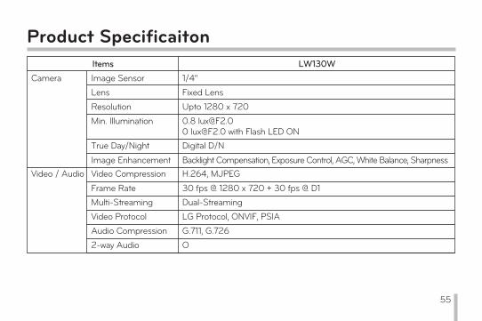
30 fps @ 1280 x 720 + 30 fps @ D1
Backlight Compensation, Exposure Control, AGC, White Balance, Sharpness
Items LW130WCamera Image Sensor 1/4"
Lens Fixed Lens
Resolution Upto 1280 x 720
True Day/Night Digital D/N
Min. Illumination 0.8 [email protected] [email protected] with Flash LED ON
Image EnhancementVideo / Audio Video Compression H.264, MJPEG
Frame RateMulti-Streaming Dual-StreamingVideo Protocol LG Protocol, ONVIF, PSIAAudio Compression G.711, G.7262-way Audio O
55
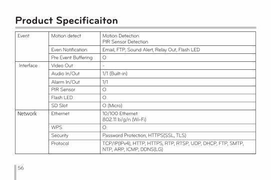
Product SpecificaitonEvent Motion detect Motion Detection
PIR Sensor DetectionEven Notification Email, FTP, Sound Alert, Relay Out, Flash LED Pre Event Buffering O
Interface Video Out -Audio In/Out 1/1 (Built-in)
Alarm In/Out 1/1PIR Sensor O
Network
SD Slot O (Micro)Ethernet 10/100 Ethernet
802.11 b/g/n (Wi-Fi)WPS OSecurity Password Protection, HTTPS(SSL, TLS)Protocol TCP/IP(IPv4), HTTP, HTTPS, RTP, RTSP, UDP, DHCP, FTP, SMTP,
NTP, ARP, ICMP, DDNS(LG)
Flash LED O
56

Product Specificaiton
Misc. Power Source DC 5VOperating Temp. 0°C ~ 40°C
Operating Humidity 0 % RH to 80 % RHWeight 100gDimension (W x H x D) Body – 60 x 98 x 42 mm
Body and Stand – 69 x 123 x 97 mm
Connections 4
Remote S/W Web ClientMobile Application (IPhone, Android)LG Video Management S/W
57
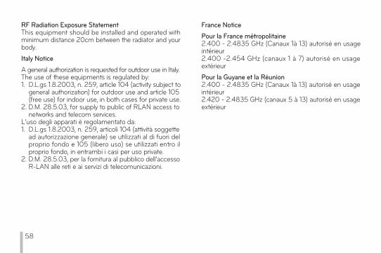
RF Radiation Exposure StatementThis equipment should be installed and operated with minimum distance 20cm between the radiator and your body.Italy NoticeA general authorization is requested for outdoor use in Italy.The use of these equipments is regulated by: 1. D.L.gs 1.8.2003, n. 259, article 104 (activity subject to general authorization) for outdoor use and article 105 (free use) for indoor use, in both cases for private use.2. D.M. 28.5.03, for supply to public of RLAN access to networks and telecom services.L’uso degli apparati è regolamentato da:1. D.L.gs 1.8.2003, n. 259, articoli 104 (attività soggette ad autorizzazione generale) se utilizzati al di fuori del proprio fondo e 105 (libero uso) se utilizzati entro il proprio fondo, in entrambi i casi per uso private. 2. D.M. 28.5.03, per la fornitura al pubblico dell’accesso R-LAN alle reti e ai servizi di telecomunicazioni.
France NoticePour la France métropolitaine2.400 - 2.4835 GHz (Canaux 1à 13) autorisé en usage intérieur 2.400 -2.454 GHz (canaux 1 à 7) autorisé en usage extérieur Pour la Guyane et la Réunion 2.400 - 2.4835 GHz (Canaux 1à 13) autorisé en usage intérieur2.420 - 2.4835 GHz (canaux 5 à 13) autorisé en usage extérieur
58
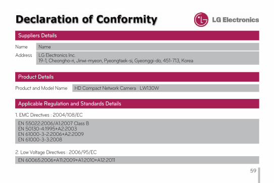
Name Name
Address LG Electronics Inc. 19-1, Cheongho-ri, Jinwi-myeon, Pyeongtaek-si, Gyeonggi-do, 451-713, Korea
Suppliers Details
Product and Model Name HD Compact Network Camera LW130W
Product Details
1. EMC Directives : 2004/108/EC
Applicable Regulation and Standards Details
EN 55022:2006/A1:2007 Class BEN 50130-4:1995+A2:2003EN 61000-3-2:2006+A2:2009EN 61000-3-3:2008
2. Low Voltage Directives : 2006/95/ECEN 60065:2006+A11:2009+A1:2010+A12:2011
59

3. R&TTE Directives : 1999/5/EC
ETSI EN 300 328 V1.7.1:2006-10ETSI EN 301 489-1 V1.8.1:2008-04ETSI EN 301 489-17 V2.1.1:2009-05
4. ErP Directives : 2009/125/EC Regulation : 278/2009/EC
The last two digits of the year in which the CE marking was affixed : 11
1588
I hereby declare under our sole responsibility that the product mentioned above to which this declaration relates complies with the above mentioned standards, regulation and directives
LG Electronics Inc. – EU Representative Veluwezoom 15, 1327 AE Almere, The Netherlands
Declaration
Name
Doo Haeng Lee / Director
Signature of representative
Oct 25, 2011
Issued Date
60