Embed Size (px)
Citation preview
Control Units
LW Series
ø22mm
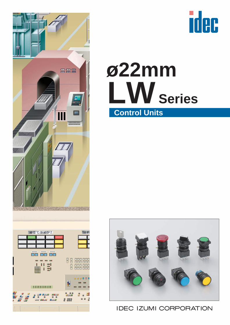
LW Series Control Units (Selection Guide)
2
ø22
Function Pushbutton
CategoryRound Flush Square Flush Round Flush with
Square Bezel Round Extended Square Extended
Momentary/Maintained
Shape
Type LW1B-∗ 1 LW2B-∗ 1 LW3B-∗ 1 LW1B-∗ 2 LW2B-∗ 2Page 5 5 5 6 6
Function Pushbutton Pilot Light (Unibody/Separate Types)
CategoryRound Extended with
Square Bezel ø30mm MushroomRound Flush Square Flush Round Flush with
Square BezelMomentary/Maintained
Shape
Type LW3B-∗ 2 LW1B-∗ 3 LW1P LW2P LW3PPage 6 6 8 8 8
Function Illuminated Pushbutton
CategoryRound Flush Round Extended Square Flush Round Flush with
Square Bezel ø30mm Mushroom
Momentary/Maintained
Shape
Type LW1L-∗ 1 LW1L-∗ 2 LW2L-∗ 1 LW3L-∗ 1 LW1L-∗ 3Page 10 10 10 11 11
Function Selector Switch Key Selector Switch
Category Round Round withSquare Bezel Round Round with
Square Bezel
Shape
Type LW1S LW3S LW1K LW3KPage 13 13 14, 15 14, 16
Function Illuminated Selector Switch Buzzer
Category Round Round withSquare Bezel
Round SquareContinuous / Intermittent
Shape
Type LW1F LW3F LW1Z LW2ZPage 18 18 19 19
3
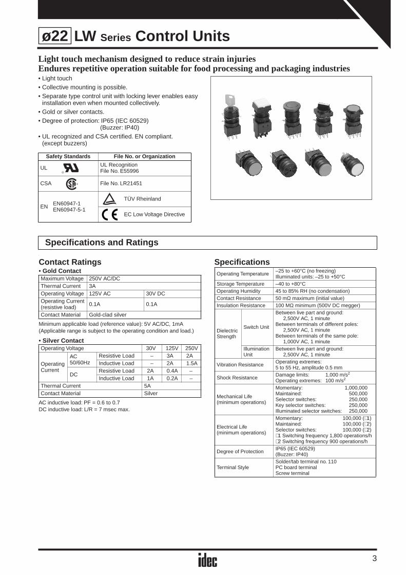
LW Series Control UnitsLight touch mechanism designed to reduce strain injuriesEndures repetitive operation suitable for food processing and packaging industries • Light touch • Collective mounting is possible.• Separate type control unit with locking lever enables easy
installation even when mounted collectively.• Gold or silver contacts.• Degree of protection: IP65 (IEC 60529)
(Buzzer: IP40)• UL recognized and CSA certified. EN compliant.
(except buzzers)
˙
Safety Standards File No. or Organization
UL UL RecognitionFile No. E55996
CSA File No. LR21451
EN EN60947-1EN60947-5-1
TÜV Rheinland
EC Low Voltage Directive
Specifications and Ratings
Contact Ratings• Gold Contact
Minimum applicable load (reference value): 5V AC/DC, 1mA(Applicable range is subject to the operating condition and load.)
• Silver Contact
AC inductive load: PF = 0.6 to 0.7DC inductive load: L/R = 7 msec max.
Specifications
Maximum Voltage 250V AC/DCThermal Current 3AOperating Voltage 125V AC 30V DCOperating Current(resistive load) 0.1A 0.1A
Contact Material Gold-clad silver
Operating Voltage 30V 125V 250V
OperatingCurrent
AC50/60Hz
Resistive Load – 3A 2AInductive Load – 2A 1.5A
DCResistive Load 2A 0.4A –Inductive Load 1A 0.2A –
Thermal Current 5AContact Material Silver
Operating Temperature –25 to +60°C (no freezing)Illuminated units: –25 to +50°C
Storage Temperature –40 to +80°COperating Humidity 45 to 85% RH (no condensation)Contact Resistance 50 mΩ maximum (initial value)Insulation Resistance 100 MΩ minimum (500V DC megger)
Dielectric Strength
Switch Unit
Between live part and ground:2,500V AC, 1 minute
Between terminals of different poles:2,500V AC, 1 minute
Between terminals of the same pole:1,000V AC, 1 minute
Illumination Unit
Between live part and ground:2,500V AC, 1 minute
Vibration Resistance Operating extremes:5 to 55 Hz, amplitude 0.5 mm
Shock Resistance Damage limits: 1,000 m/s2 Operating extremes: 100 m/s2
Mechanical Life(minimum operations)
Momentary: 1,000,000Maintained: 500,000Selector switches: 250,000Key selector switches: 250,000Illuminated selector switches: 250,000
Electrical Life(minimum operations)
Momentary: 100,000 (∗ 1)Maintained: 100,000 (∗ 2)Selector switches: 100,000 (∗ 2)∗ 1 Switching frequency 1,800 operations/h∗ 2 Switching frequency 900 operations/h
Degree of Protection IP65 (IEC 60529)(Buzzer: IP40)
Terminal StyleSolder/tab terminal no. 110PC board terminalScrew terminal
ø22
LW Series Control Units
4
ø22
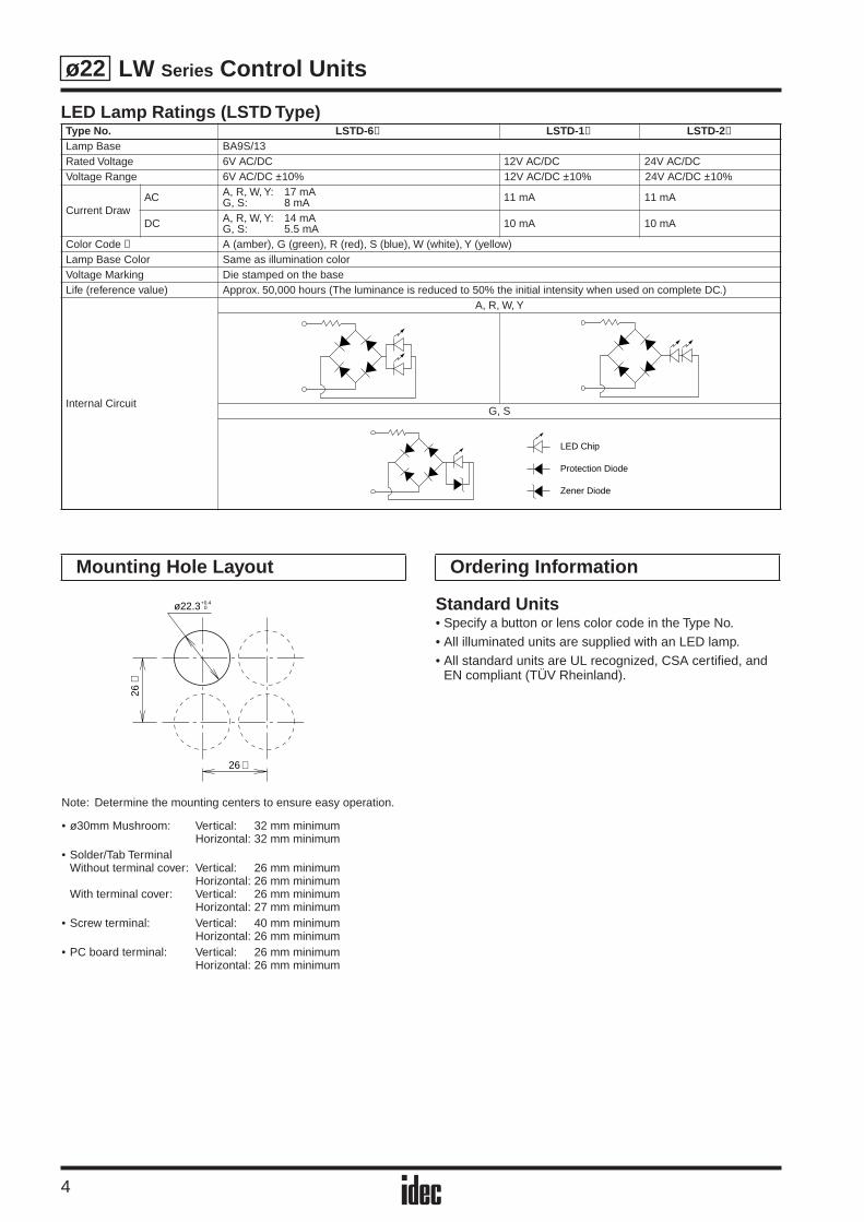
LED Lamp Ratings (LSTD Type)Type No. LSTD-6 ➁ LSTD-1➁ LSTD-2➁
Lamp Base BA9S/13Rated Voltage 6V AC/DC 12V AC/DC 24V AC/DCVoltage Range 6V AC/DC ±10% 12V AC/DC ±10% 24V AC/DC ±10%
Current DrawAC A, R, W, Y: 17 mA
G, S: 8 mA 11 mA 11 mA
DC A, R, W, Y: 14 mAG, S: 5.5 mA 10 mA 10 mA
Color Code ➁ A (amber), G (green), R (red), S (blue), W (white), Y (yellow)Lamp Base Color Same as illumination colorVoltage Marking Die stamped on the baseLife (reference value) Approx. 50,000 hours (The luminance is reduced to 50% the initial intensity when used on complete DC.)
Internal Circuit
A, R, W, Y
G, S
LED Chip
Protection Diode
Zener Diode
Note: Determine the mounting centers to ensure easy operation.
• ø30mm Mushroom: Vertical: 32 mm minimumHorizontal: 32 mm minimum
• Solder/Tab TerminalWithout terminal cover: Vertical: 26 mm minimum
Horizontal: 26 mm minimumWith terminal cover: Vertical: 26 mm minimum
Horizontal: 27 mm minimum• Screw terminal: Vertical: 40 mm minimum
Horizontal: 26 mm minimum• PC board terminal: Vertical: 26 mm minimum
Horizontal: 26 mm minimum
Standard Units• Specify a button or lens color code in the Type No.• All illuminated units are supplied with an LED lamp.• All standard units are UL recognized, CSA certified, and
EN compliant (TÜV Rheinland).
Mounting Hole Layout
ø22.3 0+0.4
26
26∗
∗
Ordering Information
LW Series Pushbuttons
5
ø22
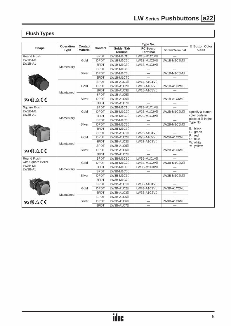
Flush Types
Shape Operation Type
ContactMaterial Contact
Type No.➀ Button Color
CodeSolder/Tab Terminal
PC Board Terminal Screw Terminal
Round FlushLW1B-M1LW1B-A1
Momentary
GoldSPDT LW1B-M1C1➀ LW1B-M1C1V➀ —
Specify a button color code in place of ➀ in the Type No.
B: blackG: greenR: redS: blueW: whiteY: yellow
DPDT LW1B-M1C2➀ LW1B-M1C2V➀ LW1B-M1C2M➀
3PDT LW1B-M1C3➀ LW1B-M1C3V➀ —
SilverSPDT LW1B-M1C5➀ — —DPDT LW1B-M1C6➀ — LW1B-M1C6M➀
3PDT LW1B-M1C7➀ — —
Maintained
GoldSPDT LW1B-A1C1➀ LW1B-A1C1V➀ —DPDT LW1B-A1C2➀ LW1B-A1C2V➀ LW1B-A1C2M➀
3PDT LW1B-A1C3➀ LW1B-A1C3V➀ —
SilverSPDT LW1B-A1C5➀ — —DPDT LW1B-A1C6➀ — LW1B-A1C6M➀
3PDT LW1B-A1C7➀ — —Square FlushLW2B-M1LW2B-A1
Momentary
GoldSPDT LW2B-M1C1➀ LW2B-M1C1V➀ —DPDT LW2B-M1C2➀ LW2B-M1C2V➀ LW2B-M1C2M➀
3PDT LW2B-M1C3➀ LW2B-M1C3V➀ —
SilverSPDT LW2B-M1C5➀ — —DPDT LW2B-M1C6➀ — LW2B-M1C6M➀
3PDT LW2B-M1C7➀ — —
Maintained
GoldSPDT LW2B-A1C1➀ LW2B-A1C1V➀ —DPDT LW2B-A1C2➀ LW2B-A1C2V➀ LW2B-A1C2M➀
3PDT LW2B-A1C3➀ LW2B-A1C3V➀ —
SilverSPDT LW2B-A1C5➀ — —DPDT LW2B-A1C6➀ — LW2B-A1C6M➀
3PDT LW2B-A1C7➀ — —Round Flush with Square BezelLW3B-M1LW3B-A1 Momentary
GoldSPDT LW3B-M1C1➀ LW3B-M1C1V➀ —DPDT LW3B-M1C2➀ LW3B-M1C2V➀ LW3B-M1C2M➀
3PDT LW3B-M1C3➀ LW3B-M1C3V➀ —
SilverSPDT LW3B-M1C5➀ — —DPDT LW3B-M1C6➀ — LW3B-M1C6M➀
3PDT LW3B-M1C7➀ — —
Maintained
GoldSPDT LW3B-A1C1➀ LW3B-A1C1V➀ —DPDT LW3B-A1C2➀ LW3B-A1C2V➀ LW3B-A1C2M➀
3PDT LW3B-A1C3➀ LW3B-A1C3V➀ —
SilverSPDT LW3B-A1C5➀ — —DPDT LW3B-A1C6➀ — LW3B-A1C6M➀
3PDT LW3B-A1C7➀ — —

LW Series Pushbuttons
6
ø22
Extended / Mushroom Types
Shape Operation Type
ContactMaterial Contact
Type No.➀ Button Color
CodeSolder/Tab Terminal
PC Board Terminal Screw Terminal
Round ExtendedLW1B-M2LW1B-A2
Momentary
GoldSPDT LW1B-M2C1➀ LW1B-M2C1V➀ —
Specify a button color code in place of ➀ in the Type No.
B: blackG: greenR: redS: blueW: whiteY: yellow
DPDT LW1B-M2C2➀ LW1B-M2C2V➀ LW1B-M2C2M➀
3PDT LW1B-M2C3➀ LW1B-M2C3V➀ —
SilverSPDT LW1B-M2C5➀ — —DPDT LW1B-M2C6➀ — LW1B-M2C6M➀
3PDT LW1B-M2C7➀ — —
Maintained
GoldSPDT LW1B-A2C1➀ LW1B-A2C1V➀ —DPDT LW1B-A2C2➀ LW1B-A2C2V➀ LW1B-A2C2M➀
3PDT LW1B-A2C3➀ LW1B-A2C3V➀ —
SilverSPDT LW1B-A2C5➀ — —DPDT LW1B-A2C6➀ — LW1B-A2C6M➀
3PDT LW1B-A2C7➀ — —Square ExtendedLW2B-M2LW2B-A2
Momentary
GoldSPDT LW2B-M2C1➀ LW2B-M2C1V➀ —DPDT LW2B-M2C2➀ LW2B-M2C2V➀ LW2B-M2C2M➀
3PDT LW2B-M2C3➀ LW2B-M2C3V➀ —
SilverSPDT LW2B-M2C5➀ — —DPDT LW2B-M2C6➀ — LW2B-M2C6M➀
3PDT LW2B-M2C7➀ — —
Maintained
GoldSPDT LW2B-A2C1➀ LW2B-A2C1V➀ —DPDT LW2B-A2C2➀ LW2B-A2C2V➀ LW2B-A2C2M➀
3PDT LW2B-A2C3➀ LW2B-A2C3V➀ —
SilverSPDT LW2B-A2C5➀ — —DPDT LW2B-A2C6➀ — LW2B-A2C6M➀
3PDT LW2B-A2C7➀ — —Round Extended with Square BezelLW3B-M2LW3B-A2 Momentary
GoldSPDT LW3B-M2C1➀ LW3B-M2C1V➀ —DPDT LW3B-M2C2➀ LW3B-M2C2V➀ LW3B-M2C2M➀
3PDT LW3B-M2C3➀ LW3B-M2C3V➀ —
SilverSPDT LW3B-M2C5➀ — —DPDT LW3B-M2C6➀ — LW3B-M2C6M➀
3PDT LW3B-M2C7➀ — —
Maintained
GoldSPDT LW3B-A2C1➀ LW3B-A2C1V➀ —DPDT LW3B-A2C2➀ LW3B-A2C2V➀ LW3B-A2C2M➀
3PDT LW3B-A2C3➀ LW3B-A2C3V➀ —
SilverSPDT LW3B-A2C5➀ — —DPDT LW3B-A2C6➀ — LW3B-A2C6M➀
3PDT LW3B-A2C7➀ — —ø30mm MushroomLW1B-M3LW1B-A3
Momentary
GoldSPDT LW1B-M3C1➀ LW1B-M3C1V➀ —DPDT LW1B-M3C2➀ LW1B-M3C2V➀ LW1B-M3C2M➀
3PDT LW1B-M3C3➀ LW1B-M3C3V➀ —
SilverSPDT LW1B-M3C5➀ — —DPDT LW1B-M3C6➀ — LW1B-M3C6M➀
3PDT LW1B-M3C7➀ — —
Maintained
GoldSPDT LW1B-A3C1➀ LW1B-A3C1V➀ —DPDT LW1B-A3C2➀ LW1B-A3C2V➀ LW1B-A3C2M➀
3PDT LW1B-A3C3➀ LW1B-A3C3V➀ —
SilverSPDT LW1B-A3C5➀ — —DPDT LW1B-A3C6➀ — LW1B-A3C6M➀
3PDT LW1B-A3C7➀ — —
LW Series Pushbuttons
7
ø22
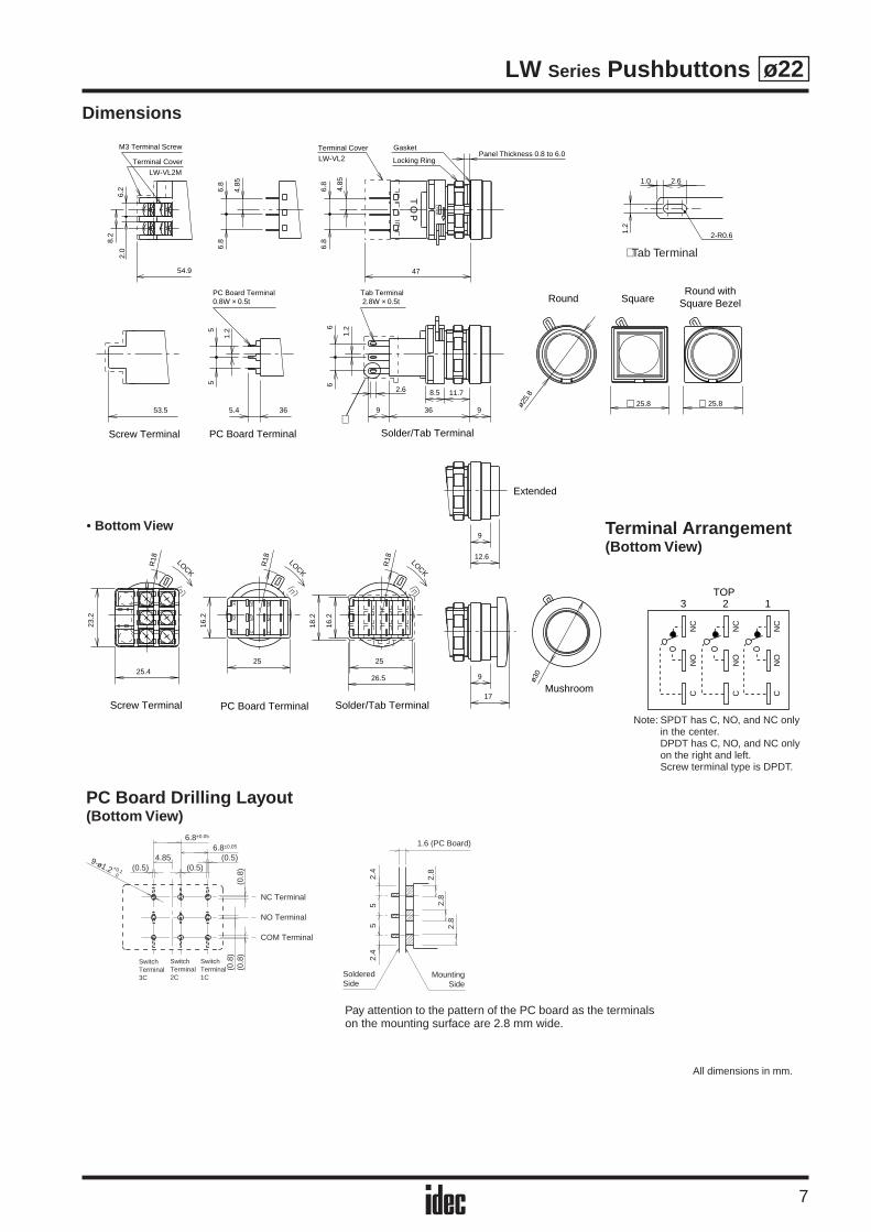
Dimensions
Locking Ring
Terminal Cover Gasket
LW-VL2
OT
P
Terminal Cover
LW-VL2M
M3 Terminal Screw
54.9
Panel Thickness 0.8 to 6.0
LOC
K
47
4.85
6.8
6.8
2.0
6.2 6.
8
4.85
6.88.
2
PC Board Terminal0.8W × 0.5t
Tab Terminal 2.8W × 0.5t
53.5 36
Solder/Tab TerminalScrew Terminal PC Board Terminal
Round withSquare BezelRound Square
1.25
5
8.5 11.7
9 36 9
1.2
2.6
66
5.4
ø25.
8
25.825.8
∗
Solder/Tab TerminalScrew Terminal PC Board Terminal
LOCK
LOCK
LOCK
CN
OX2
X1
X2
NC
NO
C
NC
25.4
23.2
R18
R18
25
16.2
R18
25
26.5
16.2
18.2
Extended
Mushroom
9ø3
09
17
12.6
2.6
2-R0.6
1.0
1.2
CN
ON
C
CN
ON
C
CN
ON
C
TOP123
Note: SPDT has C, NO, and NC only in the center. DPDT has C, NO, and NC only on the right and left.Screw terminal type is DPDT.
∗ Tab Terminal
Terminal Arrangement(Bottom View)
• Bottom View
(0.5) (0.5)(0.5)
(0.8
)(0
.8)
(0.8
)
6.8±0.05
6.8±0.05
4.85
NC Terminal
NO Terminal
COM Terminal
SwitchTerminal3C
SwitchTerminal2C
SwitchTerminal1C
9-ø1.2 +0.10
PC Board Drilling Layout(Bottom View)
Pay attention to the pattern of the PC board as the terminals on the mounting surface are 2.8 mm wide.
2.4
55
2.4
2.8
2.8
2.8
1.6 (PC Board)
MountingSide
SolderedSide
All dimensions in mm.
LW Series Pilot Lights
8
ø22
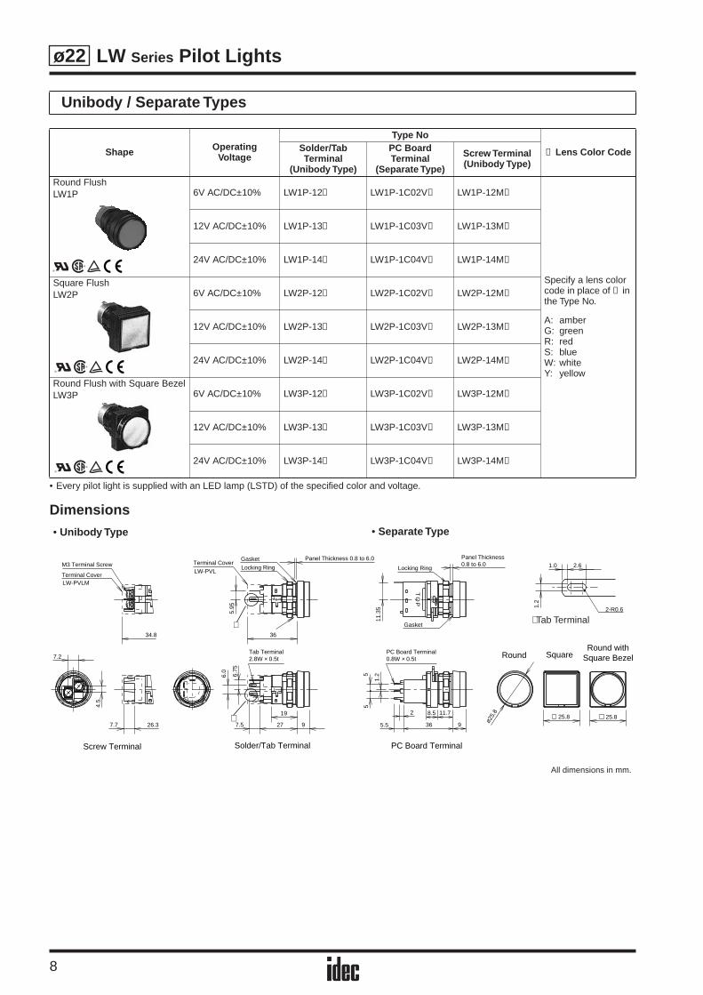
• Every pilot light is supplied with an LED lamp (LSTD) of the specified color and voltage.
Dimensions
Unibody / Separate Types
Shape OperatingVoltage
Type No
➁ Lens Color CodeSolder/Tab Terminal
(Unibody Type)
PC Board Terminal
(Separate Type)
Screw Terminal(Unibody Type)
Round FlushLW1P 6V AC/DC±10% LW1P-12➁ LW1P-1C02V➁ LW1P-12M➁
Specify a lens color code in place of ➁ in the Type No.
A: amberG: greenR: redS: blueW: whiteY: yellow
12V AC/DC±10% LW1P-13➁ LW1P-1C03V➁ LW1P-13M➁
24V AC/DC±10% LW1P-14➁ LW1P-1C04V➁ LW1P-14M➁
Square FlushLW2P 6V AC/DC±10% LW2P-12➁ LW2P-1C02V➁ LW2P-12M➁
12V AC/DC±10% LW2P-13➁ LW2P-1C03V➁ LW2P-13M➁
24V AC/DC±10% LW2P-14➁ LW2P-1C04V➁ LW2P-14M➁
Round Flush with Square BezelLW3P 6V AC/DC±10% LW3P-12➁ LW3P-1C02V➁ LW3P-12M➁
12V AC/DC±10% LW3P-13➁ LW3P-1C03V➁ LW3P-13M➁
24V AC/DC±10% LW3P-14➁ LW3P-1C04V➁ LW3P-14M➁
Solder/Tab Terminal PC Board TerminalScrew Terminal
Tab Terminal2.8W × 0.5t
PC Board Terminal0.8W × 0.5t
M3 Terminal Screw
Terminal CoverLW-PVLM
Terminal CoverLW-PVL
Gasket
Gasket
Locking Ring
Panel Thickness 0.8 to 6.0
34.8
26.3
TP OP O
36
5.95
19
7.5 27 9
6.75
6.0
7.7
7.2
4.5
Round withSquare BezelRound Square
ø25.
8
25.825.8
∗
∗8.5 11.7
5.5
2
36 9
1.25
5
Locking Ring
OT
P
Panel Thickness 0.8 to 6.0
LOC
K
11.3
5
2.6
2-R0.6
1.0
1.2
• Unibody Type • Separate Type
∗ Tab Terminal
All dimensions in mm.
LW Series Pilot Lights
9
ø22
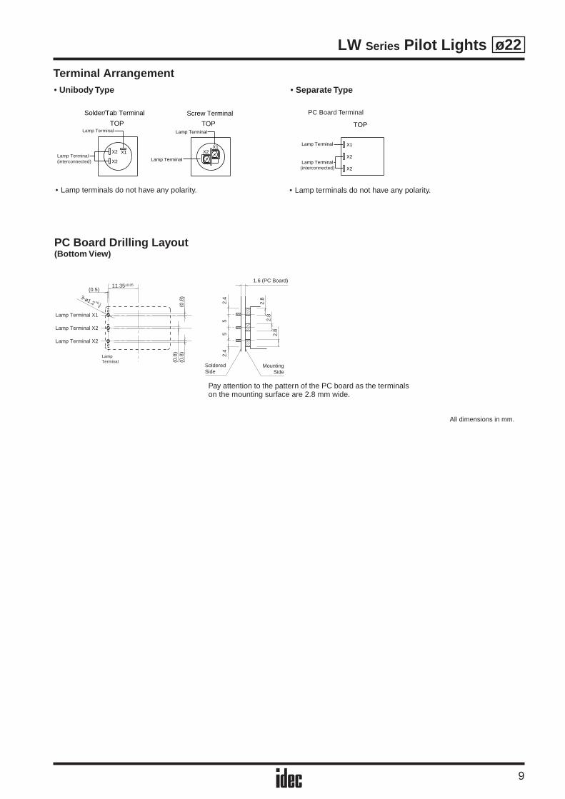
Terminal Arrangement
(0.5)
(0.8
)(0
.8)
(0.8
)
3-ø1.2 +0.10
Lamp Terminal X1
Lamp Terminal X2
Lamp Terminal X2
LampTerminal
11.35±0.05
2.4
55
2.4
2.8
2.8
2.8
1.6 (PC Board)
MountingSide
SolderedSide
Pay attention to the pattern of the PC board as the terminals on the mounting surface are 2.8 mm wide.
Lamp Terminal
Lamp Terminal
X1
X2
X2
(interconnected)
TOPTOP TOP
X2X1
X2
X1X2
Lamp Terminal
Lamp Terminal
Lamp Terminal
Lamp Terminal(interconnected)
Screw TerminalSolder/Tab Terminal
• Separate Type
PC Board Terminal
• Lamp terminals do not have any polarity. • Lamp terminals do not have any polarity.
PC Board Drilling Layout(Bottom View)
All dimensions in mm.
• Unibody Type

LW Series Illuminated Pushbuttons
10
ø22
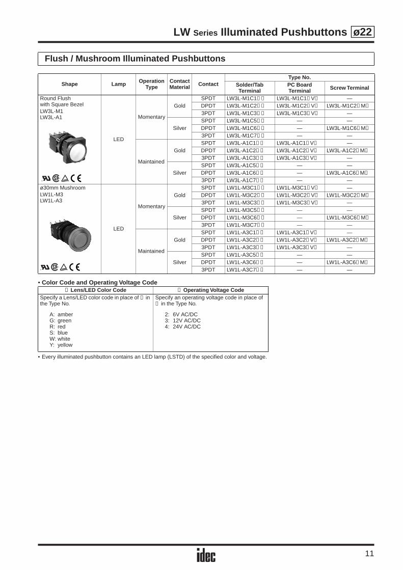
• Color Code and Operating Voltage Code
• Every illuminated pushbutton contains an LED lamp (LSTD) of the specified color and voltage.
Flush / Extended Illuminated Pushbuttons
Shape Lamp Operation Type
ContactMaterial Contact
Type No.Solder/Tab Terminal
PC Board Terminal Screw Terminal
Round FlushLW1L-M1LW1L-A1
LED
Momentary
GoldSPDT LW1L-M1C1➂➁ LW1L-M1C1➂ V➁ —DPDT LW1L-M1C2➂➁ LW1L-M1C2➂ V➁ LW1L-M1C2➂ M➁
3PDT LW1L-M1C3➂➁ LW1L-M1C3➂ V➁ —
SilverSPDT LW1L-M1C5➂➁ — —DPDT LW1L-M1C6➂➁ — LW1L-M1C6➂ M➁
3PDT LW1L-M1C7➂➁ — —
Maintained
GoldSPDT LW1L-A1C1➂➁ LW1L-A1C1➂ V➁ —DPDT LW1L-A1C2➂➁ LW1L-A1C2➂ V➁ LW1L-A1C2➂ M➁
3PDT LW1L-A1C3➂➁ LW1L-A1C3➂ V➁ —
SilverSPDT LW1L-A1C5➂➁ — —DPDT LW1L-A1C6➂➁ — LW1L-A1C6➂ M➁
3PDT LW1L-A1C7➂➁ — —Round ExtendedLW1L-M2LW1L-A2
LED
Momentary
GoldSPDT LW1L-M2C1➂➁ LW1L-M2C1➂ V➁ —DPDT LW1L-M2C2➂➁ LW1L-M2C2➂ V➁ LW1L-M2C2➂ M➁
3PDT LW1L-M2C3➂➁ LW1L-M2C3➂ V➁ —
SilverSPDT LW1L-M2C5➂➁ — —DPDT LW1L-M2C6➂➁ — LW1L-M2C6➂ M➁
3PDT LW1L-M2C7➂➁ — —
Maintained
GoldSPDT LW1L-A2C1➂➁ LW1L-A2C1➂ V➁ —DPDT LW1L-A2C2➂➁ LW1L-A2C2➂ V➁ LW1L-A2C2➂ M➁
3PDT LW1L-A2C3➂➁ LW1L-A2C3➂ V➁ —
SilverSPDT LW1L-A2C5➂➁ — —DPDT LW1L-A2C6➂➁ — LW1L-A2C6➂ M➁
3PDT LW1L-A2C7➂➁ — —Square FlushLW2L-M1LW2L-A1
LED
Momentary
GoldSPDT LW2L-M1C1➂➁ LW2L-M1C1➂ V➁ —DPDT LW2L-M1C2➂➁ LW2L-M1C2➂ V➁ LW2L-M1C2➂ M➁
3PDT LW2L-M1C3➂➁ LW2L-M1C3➂ V➁ —
SilverSPDT LW2L-M1C5➂➁ — —DPDT LW2L-M1C6➂➁ — LW2L-M1C6➂ M➁
3PDT LW2L-M1C7➂➁ — —
Maintained
GoldSPDT LW2L-A1C1➂➁ LW2L-A1C1➂ V➁ —DPDT LW2L-A1C2➂➁ LW2L-A1C2➂ V➁ LW2L-A1C2➂ M➁
3PDT LW2L-A1C3➂➁ LW2L-A1C3➂ V➁ —
SilverSPDT LW2L-A1C5➂➁ — —DPDT LW2L-A1C6➂➁ — LW2L-A1C6➂ M➁
3PDT LW2L-A1C7➂➁ — —
➁ Lens/LED Color Code ➂ Operating Voltage CodeSpecify a Lens/LED color code in place of ➁ in the Type No.
A: amberG: greenR: redS: blueW: whiteY: yellow
Specify an operating voltage code in place of ➂ in the Type No.
2: 6V AC/DC3: 12V AC/DC4: 24V AC/DC
LW Series Illuminated Pushbuttons
11
ø22
• Color Code and Operating Voltage Code
• Every illuminated pushbutton contains an LED lamp (LSTD) of the specified color and voltage.
Flush / Mushroom Illuminated Pushbuttons
Shape Lamp Operation Type
ContactMaterial Contact
Type No.Solder/Tab Terminal
PC Board Terminal Screw Terminal
Round Flushwith Square BezelLW3L-M1LW3L-A1
LED
Momentary
GoldSPDT LW3L-M1C1➂➁ LW3L-M1C1➂ V➁ —DPDT LW3L-M1C2➂➁ LW3L-M1C2➂ V➁ LW3L-M1C2➂ M➁
3PDT LW3L-M1C3➂➁ LW3L-M1C3➂ V➁ —
SilverSPDT LW3L-M1C5➂➁ — —DPDT LW3L-M1C6➂➁ — LW3L-M1C6➂ M➁
3PDT LW3L-M1C7➂➁ — —
Maintained
GoldSPDT LW3L-A1C1➂➁ LW3L-A1C1➂ V➁ —DPDT LW3L-A1C2➂➁ LW3L-A1C2➂ V➁ LW3L-A1C2➂ M➁
3PDT LW3L-A1C3➂➁ LW3L-A1C3➂ V➁ —
SilverSPDT LW3L-A1C5➂➁ — —DPDT LW3L-A1C6➂➁ — LW3L-A1C6➂ M➁
3PDT LW3L-A1C7➂➁ — —ø30mm MushroomLW1L-M3LW1L-A3
LED
Momentary
GoldSPDT LW1L-M3C1➂➁ LW1L-M3C1➂ V➁ —DPDT LW1L-M3C2➂➁ LW1L-M3C2➂ V➁ LW1L-M3C2➂ M➁
3PDT LW1L-M3C3➂➁ LW1L-M3C3➂ V➁ —
SilverSPDT LW1L-M3C5➂➁ — —DPDT LW1L-M3C6➂➁ — LW1L-M3C6➂ M➁
3PDT LW1L-M3C7➂➁ — —
Maintained
GoldSPDT LW1L-A3C1➂➁ LW1L-A3C1➂ V➁ —DPDT LW1L-A3C2➂➁ LW1L-A3C2➂ V➁ LW1L-A3C2➂ M➁
3PDT LW1L-A3C3➂➁ LW1L-A3C3➂ V➁ —
SilverSPDT LW1L-A3C5➂➁ — —DPDT LW1L-A3C6➂➁ — LW1L-A3C6➂ M➁
3PDT LW1L-A3C7➂➁ — —
➁ Lens/LED Color Code ➂ Operating Voltage CodeSpecify a Lens/LED color code in place of ➁ in the Type No.
A: amberG: greenR: redS: blueW: whiteY: yellow
Specify an operating voltage code in place of ➂ in the Type No.
2: 6V AC/DC3: 12V AC/DC4: 24V AC/DC
LW Series Illuminated Pushbuttons
12
ø22
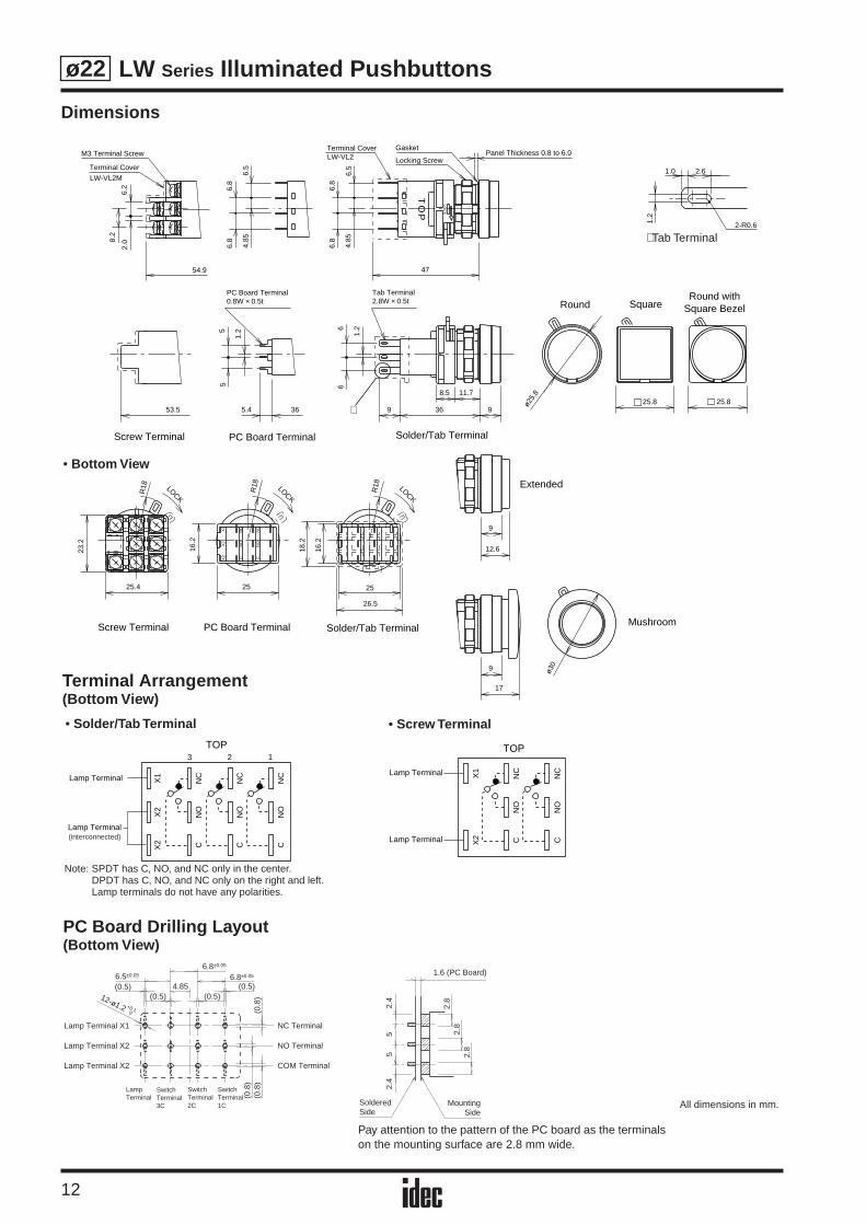
Dimensions
Locking Screw
Terminal Cover GasketLW-VL2
OT
P
Terminal Cover
LW-VL2M
M3 Terminal Screw
54.9
Panel Thickness 0.8 to 6.0
LOC
K
47
4.85
6.5
2.0
6.2
6.8
6.8
6.5
6.8
4.85
6.88.
2
53.5 36
Round withSquare BezelRound Square
1.25
5
8.5 11.7
9 36 9
1.26
6
5.4
ø25.
8
25.825.8∗
Tab Terminal2.8W × 0.5t
PC Board Terminal0.8W × 0.5t
PC Board Terminal Solder/Tab TerminalScrew Terminal
Solder/Tab TerminalScrew Terminal PC Board Terminal
LOCK
LOCK
LOCK
CN
OX2
X1
X2
NC
NO
C
NC
25.4
23.2
R18
R18
25
16.2
R18
25
26.5
16.2
18.2
X2
X2
X1
CN
ON
C
CN
ON
C
CN
ON
C
12
TOP3
(interconnected)
Lamp Terminal
Lamp Terminal
CN
ON
C
X2
X1
CN
ON
CLamp Terminal
Lamp Terminal
TOP
2.6
2-R0.6
1.0
1.2
Extended
Mushroom
9
ø309
17
12.6
(0.5)(0.5) (0.5)
(0.5)
(0.8
)(0
.8)
(0.8
)
12-ø1.2 +0.10
6.8±0.05
6.8±0.056.5±0.05
4.85
Lamp Terminal X1 NC Terminal
NO Terminal
COM Terminal
Lamp Terminal X2
Lamp Terminal X2
LampTerminal
SwitchTerminal3C
SwitchTerminal2C
SwitchTerminal1C
2.4
55
2.4
2.8
2.8
2.8
1.6 (PC Board)
MountingSide
SolderedSide
Note: SPDT has C, NO, and NC only in the center.DPDT has C, NO, and NC only on the right and left.Lamp terminals do not have any polarities.
• Bottom View
• Solder/Tab Terminal • Screw Terminal
PC Board Drilling Layout(Bottom View)
Terminal Arrangement(Bottom View)
Pay attention to the pattern of the PC board as the terminals on the mounting surface are 2.8 mm wide.
∗ Tab Terminal
All dimensions in mm.
LW Series Selector Switches
13
ø22
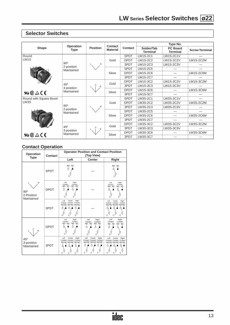
Selector Switches
Shape Operation Type Position Contact
Material ContactType No.
Solder/Tab Terminal
PC Board Terminal Screw Terminal
RoundLW1S
90º2-positionMaintained
GoldSPDT LW1S-2C1 LW1S-2C1V —DPDT LW1S-2C2 LW1S-2C2V LW1S-2C2M3PDT LW1S-2C3 LW1S-2C3V —
SilverSPDT LW1S-2C5 — —DPDT LW1S-2C6 — LW1S-2C6M3PDT LW1S-2C7 — —
45º3-positionMaintained
GoldDPDT LW1S-3C2 LW1S-3C2V LW1S-3C2M3PDT LW1S-3C3 LW1S-3C3V —
SilverDPDT LW1S-3C6 — LW1S-3C6M3PDT LW1S-3C7 — —
Round with Square BezelLW3S
90º2-positionMaintained
GoldSPDT LW3S-2C1 LW3S-2C1V —DPDT LW3S-2C2 LW3S-2C2V LW3S-2C2M3PDT LW3S-2C3 LW3S-2C3V —
SilverSPDT LW3S-2C5 — —DPDT LW3S-2C6 — LW3S-2C6M3PDT LW3S-2C7 — —
45º3-positionMaintained
GoldDPDT LW3S-3C2 LW3S-3C2V LW3S-3C2M3PDT LW3S-3C3 LW3S-3C3V —
SilverDPDT LW3S-3C6 — LW3S-3C6M3PDT LW3S-3C7 — —
L R
LC
R
L R
LC
R
Contact OperationOperation
Type ContactOperator Position and Contact Position
(Top View)Left Center Right
90º2-PositionMaintained
SPDT —
DPDT —
3PDT —
45º3-positionMaintained
DPDT
3PDT
L R
NO
C
NC NO
C
NC
C C
LeftContactNO NC
RightContact
NO NC
C C
LeftContactNO NC
RightContact
NO NC
C C C
LeftContact
CenterContact
RightContact
NO NC NO NC NO NC
C C C
LeftContact
CenterContact
RightContact
NO NC NO NC NO NC
LC
R
C C
LeftContactNO NC
RightContact
NO NC
C C
LeftContactNO NC
RightContact
NO NC
C C
LeftContactNO NC
RightContactNO NC
C C C
LeftContact
CenterContact
RightContact
NO NC NO NC NO NC
C C C
LeftContact
CenterContact
RightContact
NO NC NO NC NO NC
C C C
LeftContact
CenterContact
RightContact
NO NC NO NC NO NC
LW Series Selector Switches
14
ø22
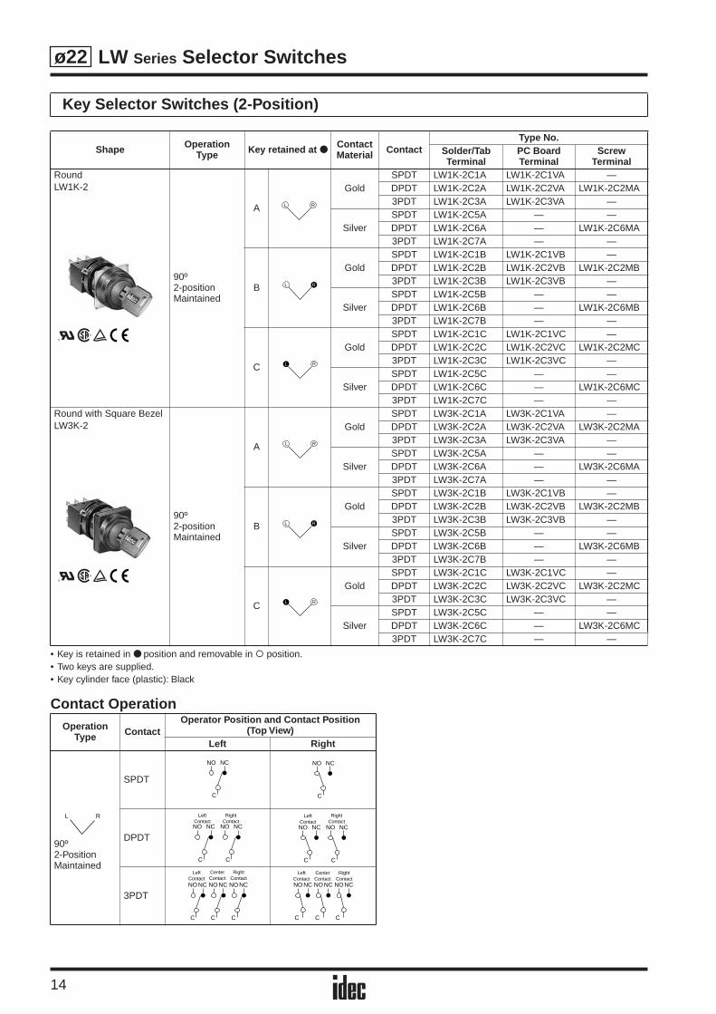
• Key is retained in position and removable in position.• Two keys are supplied.• Key cylinder face (plastic): Black
Contact Operation
Key Selector Switches (2-Position)
Shape Operation Type Key retained at
ContactMaterial Contact
Type No.Solder/Tab Terminal
PC Board Terminal
Screw Terminal
RoundLW1K-2
90º2-positionMaintained
A
GoldSPDT LW1K-2C1A LW1K-2C1VA —DPDT LW1K-2C2A LW1K-2C2VA LW1K-2C2MA3PDT LW1K-2C3A LW1K-2C3VA —
SilverSPDT LW1K-2C5A — —DPDT LW1K-2C6A — LW1K-2C6MA3PDT LW1K-2C7A — —
B
GoldSPDT LW1K-2C1B LW1K-2C1VB —DPDT LW1K-2C2B LW1K-2C2VB LW1K-2C2MB3PDT LW1K-2C3B LW1K-2C3VB —
SilverSPDT LW1K-2C5B — —DPDT LW1K-2C6B — LW1K-2C6MB3PDT LW1K-2C7B — —
C
GoldSPDT LW1K-2C1C LW1K-2C1VC —DPDT LW1K-2C2C LW1K-2C2VC LW1K-2C2MC3PDT LW1K-2C3C LW1K-2C3VC —
SilverSPDT LW1K-2C5C — —DPDT LW1K-2C6C — LW1K-2C6MC3PDT LW1K-2C7C — —
Round with Square BezelLW3K-2
90º2-positionMaintained
A
GoldSPDT LW3K-2C1A LW3K-2C1VA —DPDT LW3K-2C2A LW3K-2C2VA LW3K-2C2MA3PDT LW3K-2C3A LW3K-2C3VA —
SilverSPDT LW3K-2C5A — —DPDT LW3K-2C6A — LW3K-2C6MA3PDT LW3K-2C7A — —
B
GoldSPDT LW3K-2C1B LW3K-2C1VB —DPDT LW3K-2C2B LW3K-2C2VB LW3K-2C2MB3PDT LW3K-2C3B LW3K-2C3VB —
SilverSPDT LW3K-2C5B — —DPDT LW3K-2C6B — LW3K-2C6MB3PDT LW3K-2C7B — —
C
GoldSPDT LW3K-2C1C LW3K-2C1VC —DPDT LW3K-2C2C LW3K-2C2VC LW3K-2C2MC3PDT LW3K-2C3C LW3K-2C3VC —
SilverSPDT LW3K-2C5C — —DPDT LW3K-2C6C — LW3K-2C6MC3PDT LW3K-2C7C — —
Operation Type Contact
Operator Position and Contact Position(Top View)
Left Right
90º2-PositionMaintained
SPDT
DPDT
3PDT
L R
L R
RL
L R
L R
RL
L R
NO
C
NC NO
C
NC
C C
LeftContactNO NC
RightContact
NO NC
C C
LeftContactNO NC
RightContact
NO NC
C C C
LeftContact
CenterContact
RightContact
NO NC NO NC NO NC
C C C
LeftContact
CenterContact
RightContact
NO NC NO NC NO NC

LW Series Selector Switches
15
ø22
• Key is retained in position and removable in position.• Two keys are supplied.• Key cylinder face (plastic): Black
Contact Operation
Key Selector Switches (3-Position)
Shape Operation Type Key Retained at
ContactMaterial Contact
Type No.Solder/Tab Terminal
PC Board Terminal
Screw Terminal
RoundLW1K-3
45º3-positionMaintained
AGold
DPDT LW1K-3C2A LW1K-3C2VA LW1K-3C2MA3PDT LW1K-3C3A LW1K-3C3VA —
SilverDPDT LW1K-3C6A — LW1K-3C6MA3PDT LW1K-3C7A — —
BGold
DPDT LW1K-3C2B LW1K-3C2VB LW1K-3C2MB3PDT LW1K-3C3B LW1K-3C3VB —
SilverDPDT LW1K-3C6B — LW1K-3C6MB3PDT LW1K-3C7B — —
CGold
DPDT LW1K-3C2C LW1K-3C2VC LW1K-3C2MC3PDT LW1K-3C3C LW1K-3C3VC —
SilverDPDT LW1K-3C6C — LW1K-3C6MC3PDT LW1K-3C7C — —
DGold
DPDT LW1K-3C2D LW1K-3C2VD LW1K-3C2MD3PDT LW1K-3C3D LW1K-3C3VD —
SilverDPDT LW1K-3C6D — LW1K-3C6MD3PDT LW1K-3C7D — —
EGold
DPDT LW1K-3C2E LW1K-3C2VE LW1K-3C2ME3PDT LW1K-3C3E LW1K-3C3VE —
SilverDPDT LW1K-3C6E — LW1K-3C6ME3PDT LW1K-3C7E — —
GGold
DPDT LW1K-3C2G LW1K-3C2VG LW1K-3C2MG3PDT LW1K-3C3G LW1K-3C3VG —
SilverDPDT LW1K-3C6G — LW1K-3C6MG3PDT LW1K-3C7G — —
HGold
DPDT LW1K-3C2H LW1K-3C2VH LW1K-3C2MH3PDT LW1K-3C3H LW1K-3C3VH —
SilverDPDT LW1K-3C6H — LW1K-3C6MH3PDT LW1K-3C7H — —
Operation Type Contact
Operator Position and Contact Position(Top View)
Left Center Right
45º3-positionMaintained
DPDT
3PDT
CL R
CL R
CL RR
CL R
L CRR
L C R
RCL
LC
R
C C
LeftContactNO NC
RightContact
NO NC
C C
LeftContactNO NC
RightContact
NO NC
C C
LeftContactNO NC
RightContactNO NC
C C C
LeftContact
CenterContact
RightContact
NO NC NO NC NO NC
C C C
LeftContact
CenterContact
RightContact
NO NC NO NC NO NC
C C C
LeftContact
CenterContact
RightContact
NO NC NO NC NO NC
LW Series Selector Switches
16
ø22
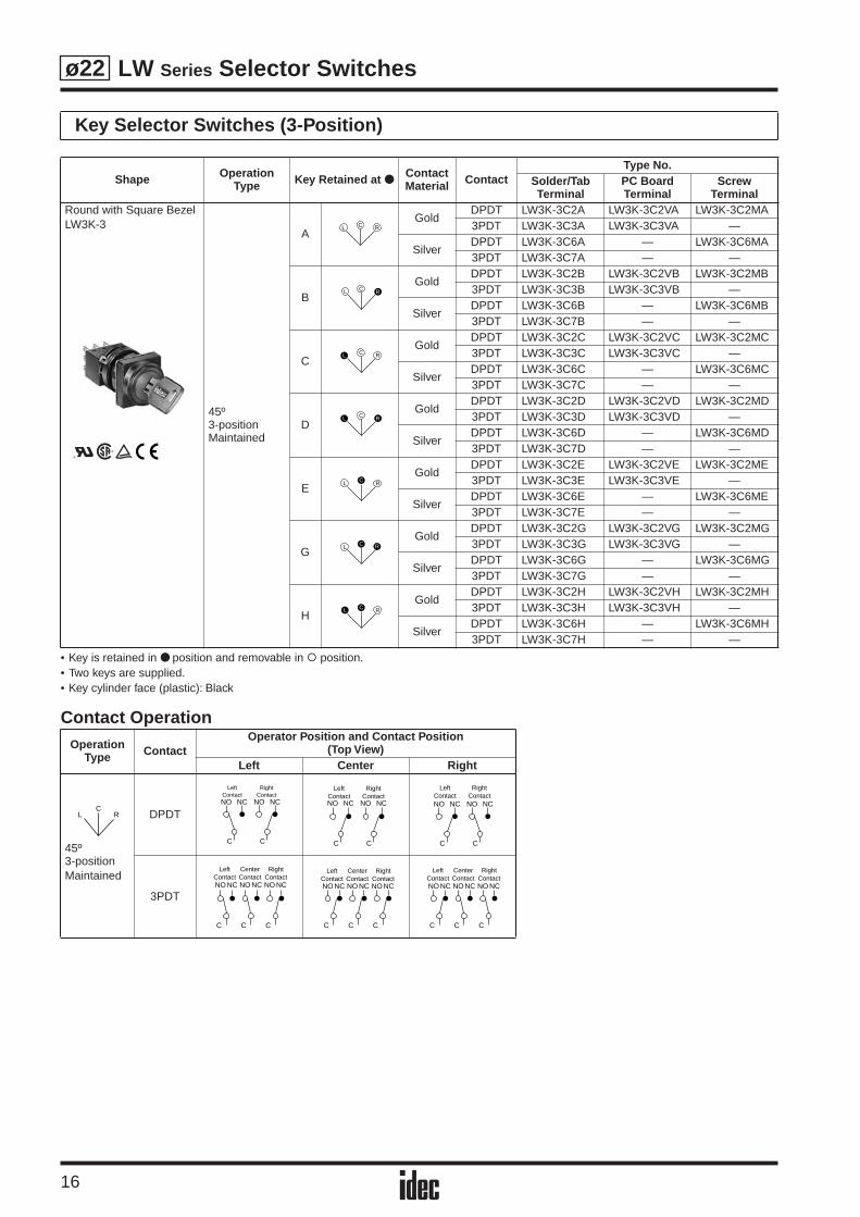
• Key is retained in position and removable in position.• Two keys are supplied.• Key cylinder face (plastic): Black
Contact Operation
Key Selector Switches (3-Position)
Shape Operation Type Key Retained at
ContactMaterial Contact
Type No.Solder/Tab Terminal
PC Board Terminal
Screw Terminal
Round with Square BezelLW3K-3
45º3-positionMaintained
AGold
DPDT LW3K-3C2A LW3K-3C2VA LW3K-3C2MA3PDT LW3K-3C3A LW3K-3C3VA —
SilverDPDT LW3K-3C6A — LW3K-3C6MA3PDT LW3K-3C7A — —
BGold
DPDT LW3K-3C2B LW3K-3C2VB LW3K-3C2MB3PDT LW3K-3C3B LW3K-3C3VB —
SilverDPDT LW3K-3C6B — LW3K-3C6MB3PDT LW3K-3C7B — —
CGold
DPDT LW3K-3C2C LW3K-3C2VC LW3K-3C2MC3PDT LW3K-3C3C LW3K-3C3VC —
SilverDPDT LW3K-3C6C — LW3K-3C6MC3PDT LW3K-3C7C — —
DGold
DPDT LW3K-3C2D LW3K-3C2VD LW3K-3C2MD3PDT LW3K-3C3D LW3K-3C3VD —
SilverDPDT LW3K-3C6D — LW3K-3C6MD3PDT LW3K-3C7D — —
EGold
DPDT LW3K-3C2E LW3K-3C2VE LW3K-3C2ME3PDT LW3K-3C3E LW3K-3C3VE —
SilverDPDT LW3K-3C6E — LW3K-3C6ME3PDT LW3K-3C7E — —
GGold
DPDT LW3K-3C2G LW3K-3C2VG LW3K-3C2MG3PDT LW3K-3C3G LW3K-3C3VG —
SilverDPDT LW3K-3C6G — LW3K-3C6MG3PDT LW3K-3C7G — —
HGold
DPDT LW3K-3C2H LW3K-3C2VH LW3K-3C2MH3PDT LW3K-3C3H LW3K-3C3VH —
SilverDPDT LW3K-3C6H — LW3K-3C6MH3PDT LW3K-3C7H — —
Operation Type Contact
Operator Position and Contact Position(Top View)
Left Center Right
45º3-positionMaintained
DPDT
3PDT
CL R
CL R
CL RR
CL R
L CRR
L C R
RCL
LC
R
C C
LeftContactNO NC
RightContact
NO NC
C C
LeftContactNO NC
RightContact
NO NC
C C
LeftContactNO NC
RightContactNO NC
C C C
LeftContact
CenterContact
RightContact
NO NC NO NC NO NC
C C C
LeftContact
CenterContact
RightContact
NO NC NO NC NO NC
C C C
LeftContact
CenterContact
RightContact
NO NC NO NC NO NC
LW Series Selector Switches
17
ø22
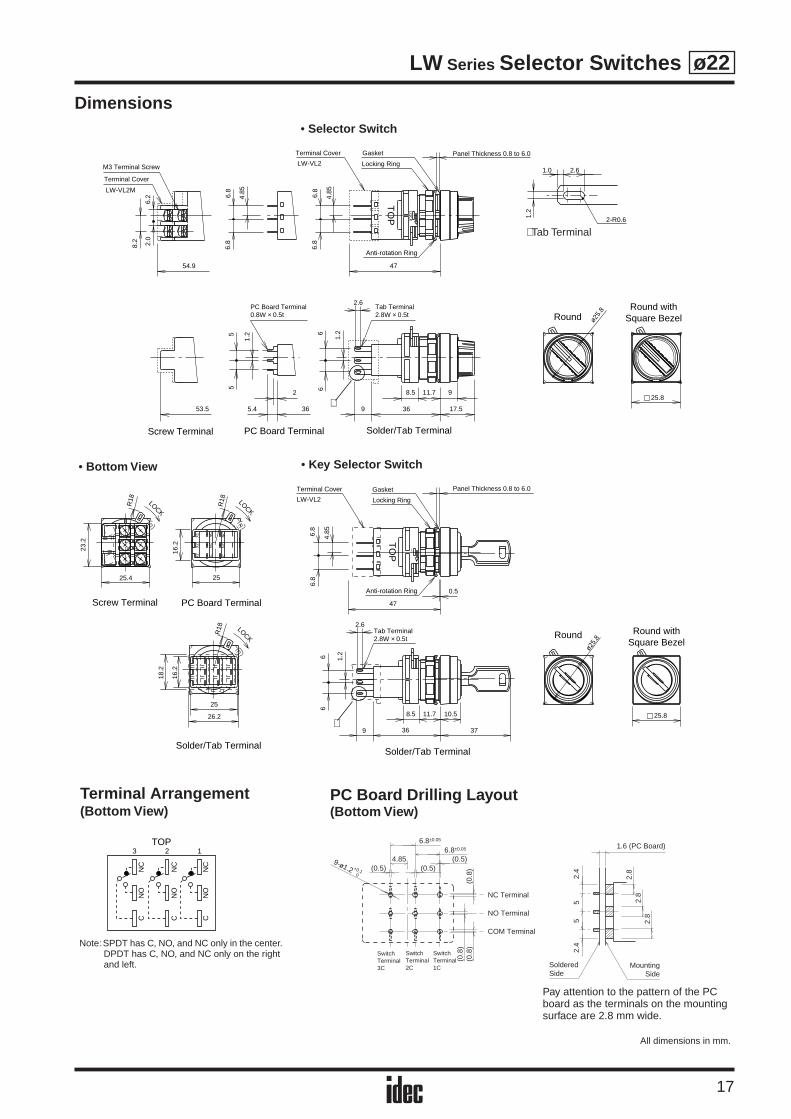
Dimensions
Anti-rotation Ring
LW-VL2
OT
P
LW-VL2M
54.9
LOC
K
47
4.85
6.8
6.8
6.8
4.85
6.8
8.2
3653.5
ø25.
8
25.88.5 11.7 9
9 36 17.5
1.26
6
2
5.4
1.25
5
∗
2.0
6.2
2.6
M3 Terminal Screw
Terminal Cover
Terminal Cover Gasket
Locking Ring
Panel Thickness 0.8 to 6.0
PC Board Terminal0.8W × 0.5t
Tab Terminal2.8W × 0.5t
Screw Terminal Solder/Tab TerminalPC Board Terminal
RoundRound with
Square Bezel
2.6
2-R0.6
1.0
1.2
LOCK
LOCK
LOCK
NC
CN
O
X2
X1
X2
NC
NO
C
25
26.2
16.2
18.2
R18
R18
25
16.2
23.2
25.4
R18
Screw Terminal PC Board Terminal
Solder/Tab Terminal
LOC
K
Anti-rotation Ring
LW-VL2
0.5
47
6.8
4.85
6.8
369
8.5 11.7
66 1.2
10.5
37
ø25.
8
25.8
TO
P
2.6
Terminal Cover Gasket
Locking Ring
Panel Thickness 0.8 to 6.0
Tab Terminal2.8W × 0.5t Round Round with
Square Bezel
Solder/Tab Terminal
∗
CN
ON
C
CN
ON
C
CN
ON
C
TOP3 2 1
∗ Tab Terminal
• Bottom View
Note:SPDT has C, NO, and NC only in the center. DPDT has C, NO, and NC only on the right and left.
Terminal Arrangement(Bottom View)
All dimensions in mm.
• Key Selector Switch
• Selector Switch
(0.5) (0.5)(0.5)
(0.8
)(0
.8)
(0.8
)
6.8±0.05
6.8±0.05
4.85
NC Terminal
NO Terminal
COM Terminal
SwitchTerminal3C
SwitchTerminal2C
SwitchTerminal1C
9-ø1.2 +0.10
PC Board Drilling Layout(Bottom View)
Pay attention to the pattern of the PC board as the terminals on the mounting surface are 2.8 mm wide.
2.4
55
2.4
2.8
2.8
2.8
1.6 (PC Board)
MountingSide
SolderedSide
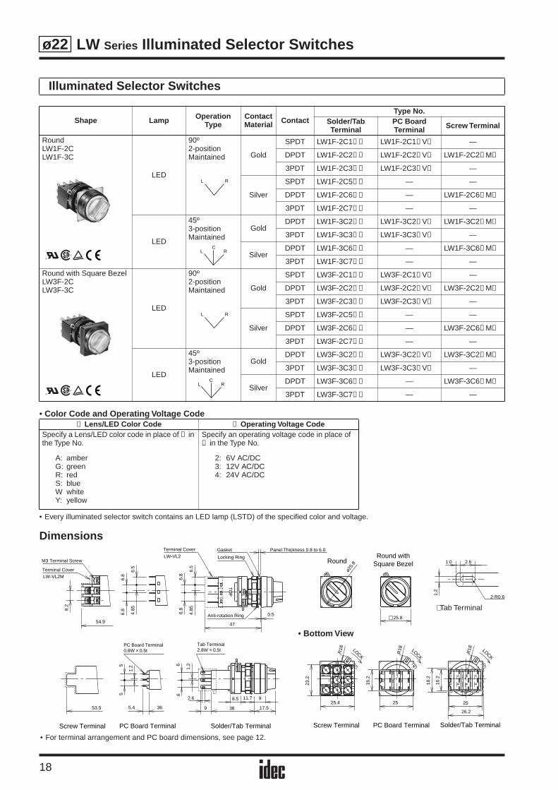
LW Series Illuminated Selector Switches
18
ø22
• Color Code and Operating Voltage Code
• Every illuminated selector switch contains an LED lamp (LSTD) of the specified color and voltage.
Dimensions
Illuminated Selector Switches
Shape Lamp Operation Type
ContactMaterial Contact
Type No.Solder/Tab Terminal
PC Board Terminal Screw Terminal
RoundLW1F-2CLW1F-3C
LED
90º2-positionMaintained Gold
SPDT LW1F-2C1➂➁ LW1F-2C1➂ V➁ —
DPDT LW1F-2C2➂➁ LW1F-2C2➂ V➁ LW1F-2C2➂ M➁
3PDT LW1F-2C3➂➁ LW1F-2C3➂ V➁ —
Silver
SPDT LW1F-2C5➂➁ — —
DPDT LW1F-2C6➂➁ — LW1F-2C6➂ M➁
3PDT LW1F-2C7➂➁ — —
LED
45º3-positionMaintained
GoldDPDT LW1F-3C2➂➁ LW1F-3C2➂ V➁ LW1F-3C2➂ M➁
3PDT LW1F-3C3➂➁ LW1F-3C3➂ V➁ —
SilverDPDT LW1F-3C6➂➁ — LW1F-3C6➂ M➁
3PDT LW1F-3C7➂➁ — —
Round with Square BezelLW3F-2CLW3F-3C
LED
90º2-positionMaintained Gold
SPDT LW3F-2C1➂➁ LW3F-2C1➂ V➁ —
DPDT LW3F-2C2➂➁ LW3F-2C2➂ V➁ LW3F-2C2➂ M➁
3PDT LW3F-2C3➂➁ LW3F-2C3➂ V➁ —
Silver
SPDT LW3F-2C5➂➁ — —
DPDT LW3F-2C6➂➁ — LW3F-2C6➂ M➁
3PDT LW3F-2C7➂➁ — —
LED
45º3-positionMaintained
GoldDPDT LW3F-3C2➂➁ LW3F-3C2➂ V➁ LW3F-3C2➂ M➁
3PDT LW3F-3C3➂➁ LW3F-3C3➂ V➁ —
SilverDPDT LW3F-3C6➂➁ — LW3F-3C6➂ M➁
3PDT LW3F-3C7➂➁ — —
➁ Lens/LED Color Code ➂ Operating Voltage CodeSpecify a Lens/LED color code in place of ➁ in the Type No.
A: amberG: greenR: redS: blueW whiteY: yellow
Specify an operating voltage code in place of ➂ in the Type No.
2: 6V AC/DC3: 12V AC/DC4: 24V AC/DC
L R
LC
R
L R
LC
R
LW-VL2
LW-VL2M
54.9
TO
P
LOC
K
0.5
47
4.85
6.5
6.8
6.8
6.5
6.8
4.85
6.88.
2
ø25.
8M3 Terminal Screw
Terminal Cover
Terminal Cover Gasket
Locking Ring
Panel Thickness 0.8 to 6.0
Anti-rotation Ring
RoundRound with
Square Bezel
25.8
53.5 36
1.25
5
8.5 11.7
9 36
1.26
6
5.4
9
17.5
2.6
LOCKLOCK
LOCK
NC
CN
O
X2
X1
X2
NC
NO
C
25
26.2
16.2
18.2
R18
R18
25
16.2
23.2
25.4
R18
PC Board Terminal0.8W × 0.5t
Tab Terminal2.8W × 0.5t
Screw Terminal Screw TerminalPC Board Terminal PC Board TerminalSolder/Tab Terminal Solder/Tab Terminal
2.6
2-R0.6
1.0
1.2
∗ Tab Terminal
• For terminal arrangement and PC board dimensions, see page 12.
• Bottom View
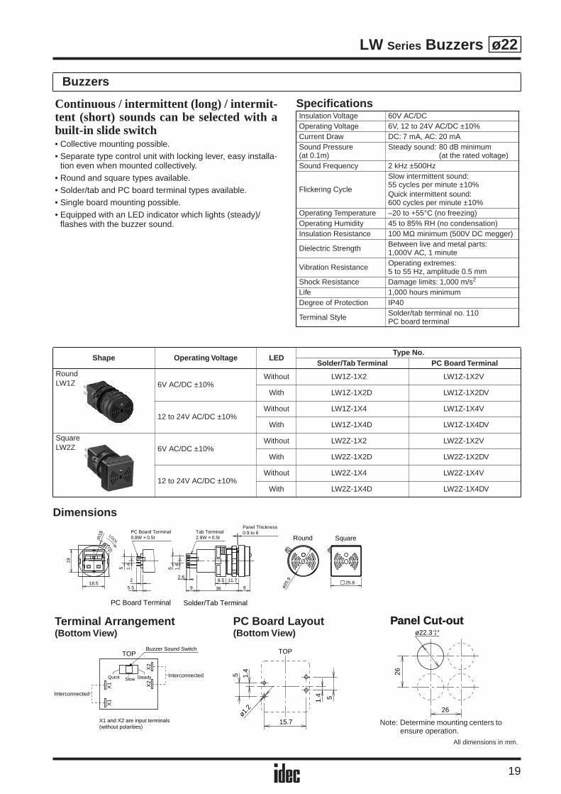
LW Series Buzzers
19
ø22
Dimensions
Buzzers
Shape Operating Voltage LEDType No.
Solder/Tab Terminal PC Board TerminalRoundLW1Z 6V AC/DC ±10%
Without LW1Z-1X2 LW1Z-1X2V
With LW1Z-1X2D LW1Z-1X2DV
12 to 24V AC/DC ±10%Without LW1Z-1X4 LW1Z-1X4V
With LW1Z-1X4D LW1Z-1X4DV
SquareLW2Z 6V AC/DC ±10%
Without LW2Z-1X2 LW2Z-1X2V
With LW2Z-1X2D LW2Z-1X2DV
12 to 24V AC/DC ±10%Without LW2Z-1X4 LW2Z-1X4V
With LW2Z-1X4D LW2Z-1X4DV
Continuous / intermittent (long) / intermit-tent (short) sounds can be selected with abuilt-in slide switch• Collective mounting possible.• Separate type control unit with locking lever, easy installa-
tion even when mounted collectively.• Round and square types available. • Solder/tab and PC board terminal types available.• Single board mounting possible.• Equipped with an LED indicator which lights (steady)/
flashes with the buzzer sound.
SpecificationsInsulation Voltage 60V AC/DCOperating Voltage 6V, 12 to 24V AC/DC ±10%Current Draw DC: 7 mA, AC: 20 mASound Pressure(at 0.1m)
Steady sound: 80 dB minimum(at the rated voltage)
Sound Frequency 2 kHz ±500Hz
Flickering Cycle
Slow intermittent sound:55 cycles per minute ±10%Quick intermittent sound:600 cycles per minute ±10%
Operating Temperature –20 to +55°C (no freezing) Operating Humidity 45 to 85% RH (no condensation)Insulation Resistance 100 MΩ minimum (500V DC megger)
Dielectric Strength Between live and metal parts:1,000V AC, 1 minute
Vibration Resistance Operating extremes: 5 to 55 Hz, amplitude 0.5 mm
Shock Resistance Damage limits: 1,000 m/s2
Life 1,000 hours minimumDegree of Protection IP40
Terminal Style Solder/tab terminal no. 110PC board terminal
LOCK
Panel Thickness0.9 to 6
X2X1
R18
18.5
19
8.5 11.7
9 36 9
1.4
61.4
5
2
5.5 ø25.
9
25.82.6
PC Board Terminal0.8W × 0.5t
Tab Terminal2.8W × 0.5t Round Square
Solder/Tab TerminalPC Board Terminal
Slow SteadyQuick
X1
X1 X2
X2
Buzzer Sound Switch
Interconnected
Interconnected
X1 and X2 are input terminals(without polarities)
TOP
1.4
5
1.4 5
15.7
ø1.2
TOP
ø22.3 0+0.4
26
26
Terminal Arrangement (Bottom View)
PC Board Layout(Bottom View)
Panel Cut-out
Note: Determine mounting centers to ensure operation.
All dimensions in mm.
Panel Cut-out
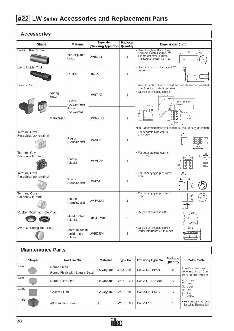
LW Series Accessories and Replacement Parts
20
ø22
Accessories
Shape Material Type No. (Ordering Type No.)
PackageQuantity Dimensions (mm)
Locking Ring Wrench
Nickel-plated brass LW9Z-T1 1
• Used to tighten the locking ring when installing the LW control unit onto a panel.
• Tightening torque: 1.2 N·m
Lamp Holder Tool
Rubber OR-55 1
• Used to install and remove LED lamps.
Switch Guard
Spring Return
Guard(polyarylate)Base(polyacetal)
LW9Z-K1 1
• Used to protect flush pushbuttons and illuminated pushbut-tons from inadvertent operation.
• Degree of protection: IP65.
Note: Determine mounting centers to ensure easy operation.
Maintained LW9Z-K11 1
Terminal CoverFor solder/tab terminal
Plastic(translucent) LW-VL2 1
• For separate type control units only.
Terminal CoverFor screw terminal
Plastic(black) LW-VL2M 1
• For separate type control units only.
Terminal CoverFor solder/tab terminal
Plastic(translucent) LW-PVL 1
• For unibody type pilot lights only.
Terminal CoverFor screw terminal
Plastic(translucent) LW-PVLM 1
• For unibody type pilot lights only.
Rubber Mounting Hole PlugNitryl rubber(black) OB-31PN05 5
• Degree of protection: IP65
Metal Mounting Hole PlugMetal (diecast)Locking nut(plastic)
LW9Z-BM 1
• Degree of protection: IP66• Panel thickness: 0.8 to 6 mm
Maintenance Parts
Shape For Use On Material Type No. Ordering Type No. PackageQuantity Color Code
Lens Round FlushPolyarylate LW9Z-L1➁ LW9Z-L1➁ PN05 5 Specify a lens color
code in place of ➁ in the Ordering Type No.
A: amberC: clearG: greenR: redS: blueY: yellow
• Use the clear (C) lens for white illumination.
Round Flush with Square Bezel
LensRound Extended Polyarylate LW9Z-L12➁ LW9Z-L12➁ PN05 5
LensSquare Flush Polyarylate LW9Z-L2➁ LW9Z-L2➁ PN05 5
Lensø30mm Mushroom AS LW9Z-L13➁ LW9Z-L13➁ 1
60
ø25.4
59
14
ø11
.6
OR-55
29.2
R
0.414.2 43.2
41.6
44.4
Panel Thickness0.8 to 4.5
17.3
31.3
25.8
26.2
18.224
2221
CX2
3231
NC
NO
34
X2
X1 12
1114
14.8
5.412.9
23.2
25.4
X1
X2
TOP
X1
X2
TOP
7.5
19.2
ø20
.6
44
14
ø20
.6
X1
X2
TOP
3.5
3.5
ø25
ø29
123
ø25.8
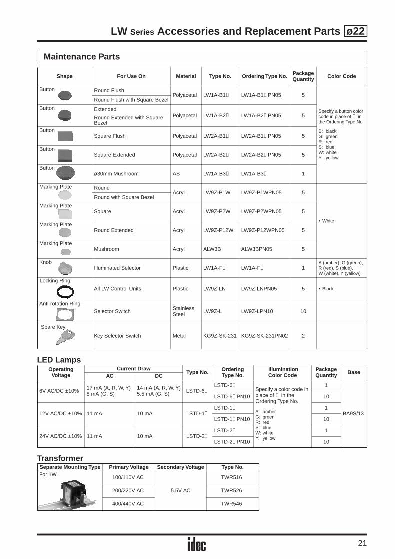
LW Series Accessories and Replacement Parts
21
ø22
LED Lamps
Transformer
Maintenance Parts
Shape For Use On Material Type No. Ordering Type No. PackageQuantity Color Code
Button Round FlushPolyacetal LW1A-B1➀ LW1A-B1➀ PN05 5
Specify a button color code in place of ➀ in the Ordering Type No.
B: blackG: greenR: redS: blueW: whiteY: yellow
Round Flush with Square Bezel
Button ExtendedPolyacetal LW1A-B2➀ LW1A-B2➀ PN05 5Round Extended with Square
BezelButton
Square Flush Polyacetal LW2A-B1➀ LW2A-B1➀ PN05 5
ButtonSquare Extended Polyacetal LW2A-B2➀ LW2A-B2➀ PN05 5
Buttonø30mm Mushroom AS LW1A-B3➀ LW1A-B3➀ 1
Marking Plate Round Acryl LW9Z-P1W LW9Z-P1WPN05 5
• White
Round with Square Bezel
Marking PlateSquare Acryl LW9Z-P2W LW9Z-P2WPN05 5
Marking PlateRound Extended Acryl LW9Z-P12W LW9Z-P12WPN05 5
Marking PlateMushroom Acryl ALW3B ALW3BPN05 5
KnobIlluminated Selector Plastic LW1A-F➁ LW1A-F➁ 1
A (amber), G (green), R (red), S (blue),W (white), Y (yellow)
All LW Control Units Plastic LW9Z-LN LW9Z-LNPN05 5 • Black
Anti-rotation RingSelector Switch Stainless
Steel LW9Z-L LW9Z-LPN10 10
Key Selector Switch Metal KG9Z-SK-231 KG9Z-SK-231PN02 2
OperatingVoltage
Current DrawType No. Ordering
Type No. IlluminationColor Code
PackageQuantity Base
AC DC
6V AC/DC ±10% 17 mA (A, R, W, Y)8 mA (G, S)
14 mA (A, R, W, Y)5.5 mA (G, S) LSTD-6➁
LSTD-6➁Specify a color code in place of ➁ in the Ordering Type No.
A: amberG: greenR: red S: blueW: whiteY: yellow
1
BA9S/13
LSTD-6➁ PN10 10
12V AC/DC ±10% 11 mA 10 mA LSTD-1➁LSTD-1➁ 1
LSTD-1➁ PN10 10
24V AC/DC ±10% 11 mA 10 mA LSTD-2➁LSTD-2➁ 1
LSTD-2➁ PN10 10
Separate Mounting Type Primary Voltage Secondary Voltage Type No.For 1W 100/110V AC
5.5V AC
TWR516
200/220V AC TWR526
400/440V AC TWR546
Locking Ring
Spare Key
LW Series Instructions
22
ø22
z
Safety Precautions
Instructions
• Turn off the power to the LW series control units before starting installation, removal, wiring, maintenance, and inspection of the products. Failure to turn power off may cause electrical shocks or fire hazard.
• To avoid burning your hand, use the lamp holder tool when replacing lamps.
• For wiring, use wires of a proper size to meet the voltage and current requirements. Solder correctly according to the instructions on “Wiring” and “Notes on Terminal Cover” on page 23. Tighten the M3 terminal screws to a torque of 0.6 to 1.0 N·m. Failure to tighten terminal screws may cause overheating and fire.
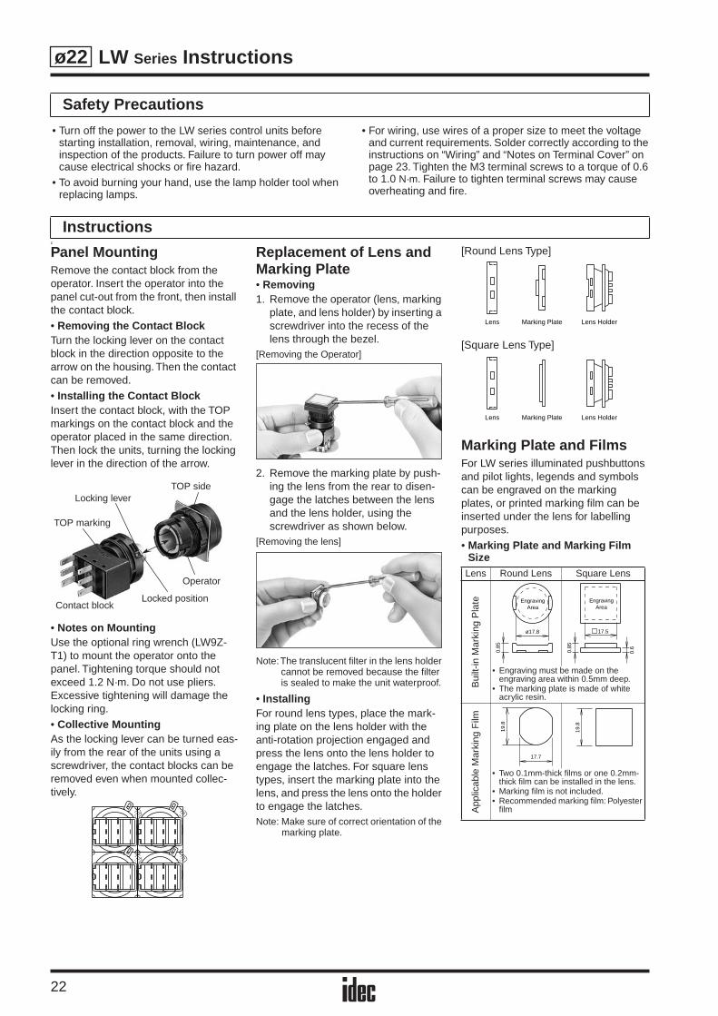
Panel MountingRemove the contact block from the operator. Insert the operator into the panel cut-out from the front, then install the contact block.• Removing the Contact BlockTurn the locking lever on the contact block in the direction opposite to the arrow on the housing. Then the contact can be removed.• Installing the Contact BlockInsert the contact block, with the TOP markings on the contact block and the operator placed in the same direction. Then lock the units, turning the locking lever in the direction of the arrow.
• Notes on MountingUse the optional ring wrench (LW9Z-T1) to mount the operator onto the panel. Tightening torque should not exceed 1.2 N·m. Do not use pliers. Excessive tightening will damage the locking ring.• Collective MountingAs the locking lever can be turned eas-ily from the rear of the units using a screwdriver, the contact blocks can be removed even when mounted collec-tively.
Replacement of Lens and Marking Plate• Removing1. Remove the operator (lens, marking
plate, and lens holder) by inserting a screwdriver into the recess of the lens through the bezel.
[Removing the Operator]
2. Remove the marking plate by push-ing the lens from the rear to disen-gage the latches between the lens and the lens holder, using the screwdriver as shown below.
[Removing the lens]
Note:The translucent filter in the lens holder cannot be removed because the filter is sealed to make the unit waterproof.
• InstallingFor round lens types, place the mark-ing plate on the lens holder with the anti-rotation projection engaged and press the lens onto the lens holder to engage the latches. For square lens types, insert the marking plate into the lens, and press the lens onto the holder to engage the latches.Note: Make sure of correct orientation of the
marking plate.
[Round Lens Type]
[Square Lens Type]
Marking Plate and FilmsFor LW series illuminated pushbuttons and pilot lights, legends and symbols can be engraved on the marking plates, or printed marking film can be inserted under the lens for labelling purposes.• Marking Plate and Marking Film
Size
TOP side
Operator
Locking lever
TOP marking
Contact blockLocked position
Lens Round Lens Square Lens
Bui
lt-in
Mar
king
Pla
teA
pplic
able
Mar
king
Film
Lens Marking Plate Lens Holder
Lens Marking Plate Lens Holder
EngravingArea
ø17.8
0.85
EngravingArea
0.85
0.6
17.5
17.7
19.8
19.8
• Two 0.1mm-thick films or one 0.2mm-thick film can be installed in the lens.
• Marking film is not included.• Recommended marking film: Polyester
film
• Engraving must be made on the engraving area within 0.5mm deep.
• The marking plate is made of white acrylic resin.
LW Series Instructions
23
ø22
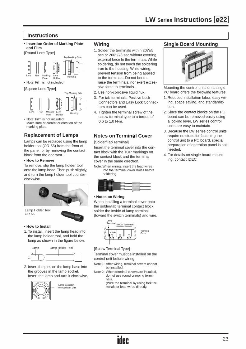
Instructions• Insertion Order of Marking Plate
and Film[Round Lens Type]
• Note: Film is not included
[Square Lens Type]
• Note: Film is not includedMake sure of correct orientation of the marking plate.
Replacement of LampsLamps can be replaced using the lamp holder tool (OR-55) from the front of the panel, or by removing the contact block from the operator.• How to RemoveTo remove, slip the lamp holder tool onto the lamp head. Then push slightly, and turn the lamp holder tool counter-clockwise.
• How to Install1. To install, insert the lamp head into
the lamp holder tool, and hold the lamp as shown in the figure below.
2. Insert the pins on the lamp base into the grooves in the lamp socket. Insert the lamp and turn it clockwise.
Wiring1. Solder the terminals within 20W/5
sec or 260°C/3 sec without exerting external force to the terminals. While soldering, do not touch the soldering iron to the housing. While wiring, prevent tension from being applied to the terminals. Do not bend or raise the terminals, nor exert exces-sive force to terminals.
2. Use non-corrosive liquid flux.3. For tab terminals, Positive Lock
Connectors and Easy Lock Connec-tors can be used.
4. Tighten the terminal screw of the screw terminal type to a torque of 0.6 to 1.0 N·m.
Notes on Termin l Cover
[Solder/Tab Terminal]Insert the terminal cover into the con-tact block with the TOP markings on the contact block and the terminal cover in the same direction.
Note: When wiring, insert the lead wires into the terminal cover holes before soldering.
•
Notes on Wiring
When installing a terminal cover onto the solder/tab terminal contact block, solder the inside of lamp terminal (toward the switch terminals) and wire.
[Screw Terminal Type]Terminal cover must be installed on the control unit before wiring.
Note 1: After wiring, terminal covers cannot be installed.
Note 2: When terminal covers are installed, do not use round crimping termi-nals.(Wire the terminal by using fork ter-minals or lead wires directly.
Single Board Mounting
Mounting the control units on a single PC board offers the following features.1. Reduced installation labor, easy wir-
ing, space saving, and standardiz-tion.
2. Since the contact blocks on the PC board can be removed easily using a locking lever, LW series control units are easy to maintain.
3. Because the LW series control units require no studs for fastening the control unit to a PC board, special preparation of operation panel is not needed.
4. For details on single board mount-ing, contact IDEC.
Top Marking Side
Lens Film MarkingPlate
LensHolder
Housing
Lens Film MarkingPlate
LensHolder
Housing
Top Marking Side
Lamp Holder ToolOR-55
Lamp Holder ToolLamp
Lamp Socket inthe Operator Unit
LampTerminal Switch Terminals
InsideTerminalCover

IDEC CORPORATION (USA)1175 Elko Drive, Sunnyvale, CA 94089-2209, USATel: +1-408-747-0550, Toll Free: (800) 262-IDEC, Fax: +1-408-744-9055E-mail: [email protected], www.idec.com
IDEC CANADA LIMITEDUnit 22-151, Brunel Road Mississauga, Ontario, L4Z 1X3, CanadaTel: +1-905-890-8561, Toll Free: (888) 317-4332, Fax: +1-905-890-8562
IDEC ELECTRONICS LIMITEDUnit 2, Beechwood, Chineham Business Park, Basingstoke, HampshireRG24 8WA, UKTel: +44-1256-321000, Fax: +44-1256-327755E-mail: [email protected]
IDEC ELEKTROTECHNIK GmbHWendenstrasse 331, D-20537 Hamburg, GermanyTel: +49-40-25 30 54 10, Fax: +49-40-25 30 54 24E-mail: [email protected], www.idec.de
IDEC AUSTRALIA PTY. LTD.2/3 Macro Court, Rowville, Victoria 3178, AustraliaToll Free: 1-800-68-4332, Fax: +61-3-9763-3255E-mail: [email protected]
7-31, Nishi-Miyahara 1-Chome, Yodogawa-ku, Osaka 532-8550, JapanTel: +81-6-6398-2571, Fax: +81-6-6392-9731www.idec.com
Specifications and other descriptions in this catalog are subject to change without notice.
Cat. No. EP1097-0 SEPTEMBER 2005 8DNP PRINTED IN JAPAN
IDEC IZUMI ASIA PTE. LTD.No. 31, Tannery Lane #05-01, Dragon Land Building, Singapore 347788Tel: +65-6746-1155, Fax: +65-6844-5995E-mail: [email protected]
IDEC IZUMI (H.K.) CO., LTD.Unit 1505-07, DCH Commercial Centre No. 25, Westlands Road,Quarry Bay, Hong KongTel: +852-2803-8989, Fax: +852-2565-0171E-mail: [email protected]
IDEC IZUMI (Shanghai) Co., Ltd.Room E, 15F, Majesty Building, No. 138 Pudong Avenue, Shanghai 200120, P.R.C.Tel: +86-21-5887-9181, Fax: +86-21-5887-8930E-mail: [email protected]
IDEC TAIWAN CORPORATION8F, No. 79, Hsin Tai Wu Road, Sec. 1, Hsi-Chih, Taipei County, TaiwanTel: +886-2-2698-3929, Fax: +886-2-2698-3931E-mail: [email protected]