Embed Size (px)
Citation preview
Cable Carriers
Information about further items of our productrange is available on request:
• Copper head rails• Current collectors• Insulators• Plastic- and neoprene-cables• Junction boxes• Cable reels• Radio remote control units• Anti-collision devices
Eisenstraße 1D-57489 Drolshagen-Scheda
Germany
Tel.: +49 2763 / 211 482FAX: +49 2763 / 211 484

31
500 SeriesSteel(galvanised)
500 series cable carriers are suitable for medium duty applications in arduous conditions, and are ideal in installations inrestricted areas because of their moderate dimensions.
The system is suitable for either internal or external applications.
The carrier and cable support are made of aluminium giving strength whilst light in weight, the rollers have dust proof and watertight seals, and the precision bearings are packed with grease giving many hours of trouble free operation.
Please note: All parts in this series are available in stainless steel.
Technical dataTack: Special box section track Ref. No. 500
in length of 6 metres.Distance between suspension supports: Normally every 2 metres, but every 1 metre within the stack section.Maximum admissible capacity ofcarrier: max. 25 kg
Maximum admissible number of cables: six round cables of 23 mm diameter each orflat cable up to 16.9 mm thick
35 mm thickMaximum cable capacity:for round cable: 23 mm ∅ for flat cable
97 mm wideRollers: Steel rollers with dust and water protected ball bearings.
Bearings pre-packed with grease suitable fortemperature range –30°C to + 125°C
Cable fastening: By neoprene clamping pieces.Material spec.: Carrier and supports of corrosion resistant aluminium and steel.
All screws suitably rust-proofed.Applications: For medium sized mobile installations. Suitable for interior or exterior applications.Each installation requires:
1) Requisite number of carriers2) One end clamp with buffer stop3) One leading carrier4) Special box section track5) Suspension brackets (every 2metres)6) Box section joints (every 6 metrees)7) Two end covers (only required with exteriorapplications)8) The corresponding number of cable cleats
No. 500No. 582 or 584No. 588No. 595

32
500 SeriesSpecial boxsection track(galv. steel)
For cable carriers Part No. K 501 – K 517
Material: steel (galvanised)Standard length: 6 metresSupport distance: 2 metres
Part No.Momentof stressJ x cm4
Momentof resistW x cm³
kg/m
500 6.92 3.15 2.550
Suspensionbrackets(galv. steel)
These brackets should be used every 2 metres on the normal track but every 1 metre within the stack section.
Part No.. 582Weight: 0.6 kg/each
Part No.: 584Weight: 0.5 kg/each
Track joints(galv. steel) In order to avoid the ingress of dirt and water it is necessary to insulate all joints with a plastic insulation (supplied).
Part No.: 588Weight: 1.0 kg/each
Endcover for track(soft PVC) These end covers are necessary in all external applications
Part No. A B C kg/ea.595 47 48 45 0.035
33
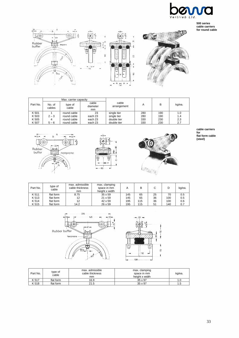
500 seriescable carriersfor round cable
Max. carrier capacity
Part No. No. ofcables
type ofcable
cablediameter
mm
cablearrangement A B kg/ea.
K 501 1 round cable 23 single tier 280 190 1.0K 503 2 – 3 round cable each 23 single tier 280 190 1.4K 505 4 round cable each 23 double tier 330 230 2.3K 507 5 – 6 round cable each 23 double tier 330 230 2.7
cable carriersforflat form cable(steel)
Part No. type ofcable
max. admissiblecable thickness
mm
max. clampingspace in mmheight x width
A B C D kg/ea.
K 511 flat form 8.75 35 x 59 145 65 25 70 0.5K 513 flat form 12 21 x 59 145 65 36 100 0.5K 514 flat form 12 42 x 59 195 115 36 100 0.6K 515 flat form 14.2 26 x 59 195 115 51 140 0.7
Part No. type ofcable
max. admissiblecable thickness
mm
max. clampingspace in mmheight x width
kg/ea.
K 517 flat form 16.9 35 x 97 1.0K 518 flat form 21.5 35 x 97 1.5

34
The leading carrier is joined to the trolley by a tubular outrigger approximately 35 mm diameter. It is essential that theoutrigger is located centrally in the rectangular section of the leading carrier and that it is free to move horizontally within thisrectangular section.
500 SeriesLeading carrierforround and flatcable(steel)
cablesPart No. For cable
carrier No. No. typeA B C kg/ea.
M 501 K 501 1 round 280 90 150 1.7M 503 K 503 2 – 3 round 280 90 150 2.1M 505 K 505 4 round 330 90 150 3.0M 507 K 507 5 - 6 round 330 90 150 3.4M 511 K 511 - flat form 145 85 140 0.9M 513 K 513 - flat form 145 85 140 0.9M 514 K 514 - flat form 195 85 140 1.0M 515 K 515 - flat form 195 85 140 1.1M 517 K 517 - flat form 235 90 150 1.7M 518 K 518 - flat form 300 90 150 1.9
Cable cleatsforround cable
The fitting of cable cleats is recommended with round cables in order to avoid entanglement of the cables caused when thefestoon system in subjected to changes of direction or side movements for example high winds.The clamping pieces of the cable cleats are made of hardwood impregnated with wood preservative and are fastenedbetween aluminium frames. When ordering please specify the exact cable diameters or alternatively we can supply cleatsundrilled.When using two tier cable carriers the cable cleats should be installed in such a way that they cannot touch each other, alsothe nuts on the clamping bolts should be on the outside to prevent damage to the cable.
Part No. For cablecarrier No. No of cables A B C kg/ea.
S 328 K 503 – K 507 3 125 56 33 0.24
35
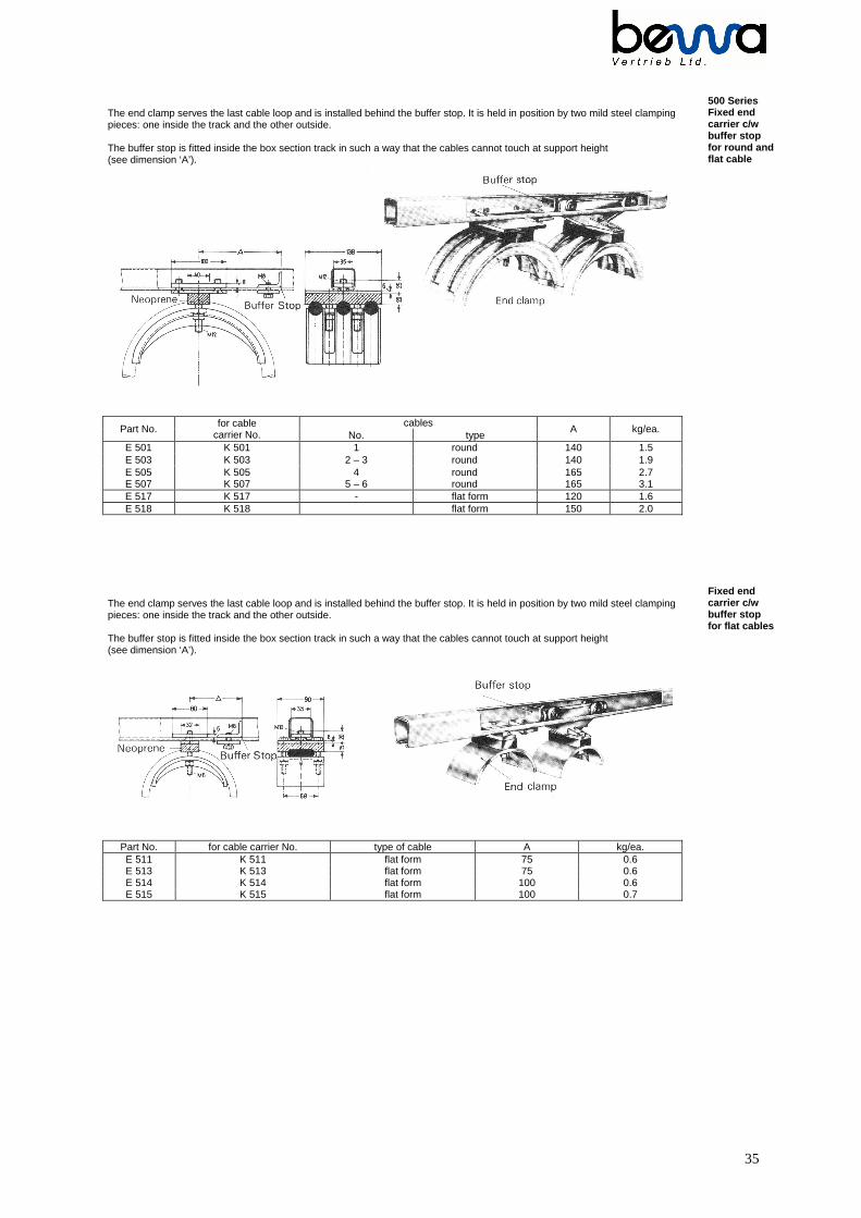
The end clamp serves the last cable loop and is installed behind the buffer stop. It is held in position by two mild steel clampingpieces: one inside the track and the other outside.
The buffer stop is fitted inside the box section track in such a way that the cables cannot touch at support height(see dimension ‘A’).
cablesPart No. for cable
carrier No. No. typeA kg/ea.
E 501 K 501 1 round 140 1.5E 503 K 503 2 – 3 round 140 1.9E 505 K 505 4 round 165 2.7
500 SeriesFixed endcarrier c/wbuffer stopfor round andflat cable
E 507 K 507 5 – 6 round 165 3.1E 517 K 517 - flat form 120 1.6E 518 K 518 flat form 150 2.0
The end clamp serves the last cable loop and is installed behind the buffer stop. It is held in position by two mild steel clampingpieces: one inside the track and the other outside.
The buffer stop is fitted inside the box section track in such a way that the cables cannot touch at support height(see dimension ‘A’).
Fixed endcarrier c/wbuffer stopfor flat cables
Part No. for cable carrier No. type of cable A kg/ea.E 511 K 511 flat form 75 0.6E 513 K 513 flat form 75 0.6E 514 K 514 flat form 100 0.6E 515 K 515 flat form 100 0.7