Embed Size (px)
Citation preview
© ABB Inc.July 24, 2014 | Slide 1
LV and MV Drives 101
R Hoadley, 22 July 2014
LV and MV Drives 101
© ABB GroupJuly 24, 2014 | Slide 2
Speaker name: Rick Hoadley
Speaker title: Principle Consulting Applications Engineer
Medium Voltage Drives
Company name: ABB
Location: New Berlin, WI
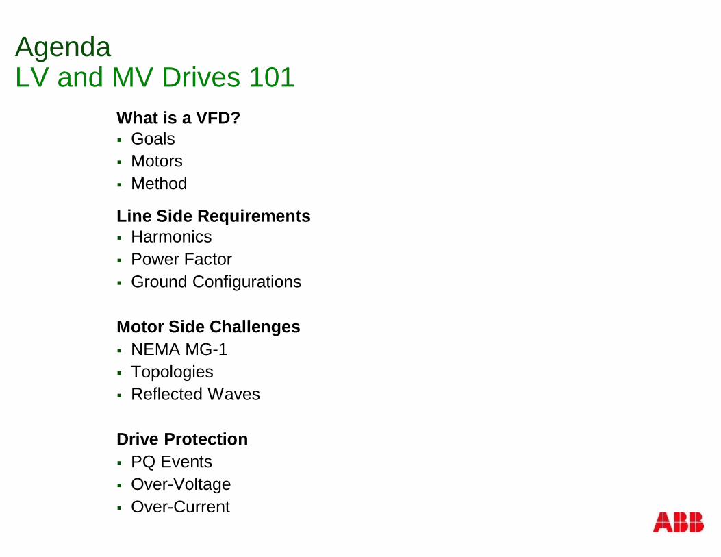
AgendaLV and MV Drives 101
What is a VFD?§ Goals§ Motors§ Method
Line Side Requirements§ Harmonics§ Power Factor§ Ground Configurations
Motor Side Challenges§ NEMA MG-1§ Topologies§ Reflected Waves
Drive Protection§ PQ Events§ Over-Voltage§ Over-Current
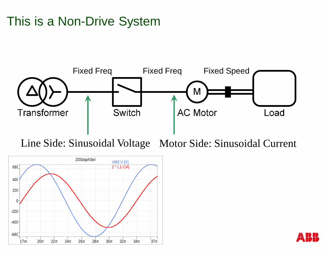
This is a Non-Drive System
Fixed Freq Fixed Freq Fixed Speed
-680
680
-400
-200
0
200
400
17m 37m20m 22m 24m 26m 28m 30m 32m 34m
2DGraphSel1 VM2.V [V] 2 * L1.I [A]
Motor Side: Sinusoidal CurrentLine Side: Sinusoidal Voltage
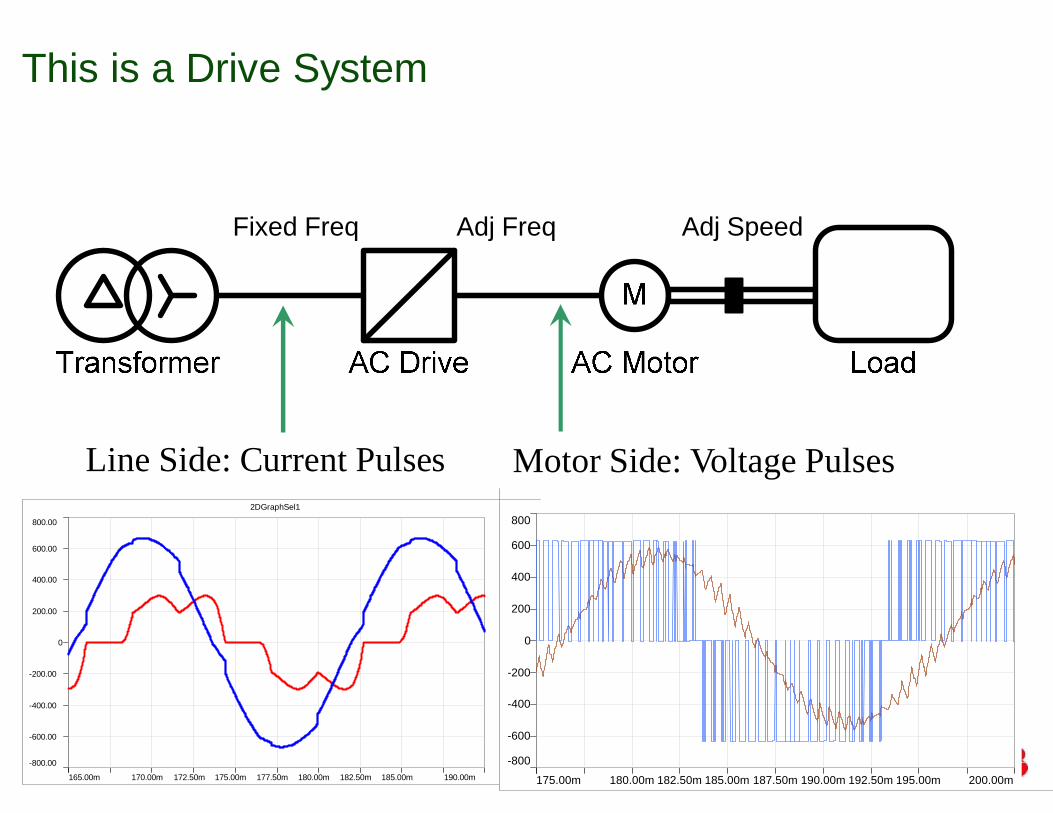
This is a Drive System
Fixed Freq Adj Freq Adj Speed
Line Side: Current Pulses Motor Side: Voltage Pulses
-800.00
800.00
-600.00
-400.00
-200.00
0
200.00
400.00
600.00
165.00m 190.00m170.00m 172.50m 175.00m 177.50m 180.00m 182.50m 185.00m
2DGraphSel1
L1.I [A] VMab....
-800
800
-600
-400
-200
0
200
400
600
175.00m 200.00m180.00m 182.50m 185.00m 187.50m 190.00m 192.50m 195.00m
AMmu.I [A] VMmuv.V...
Why are AC drives used?
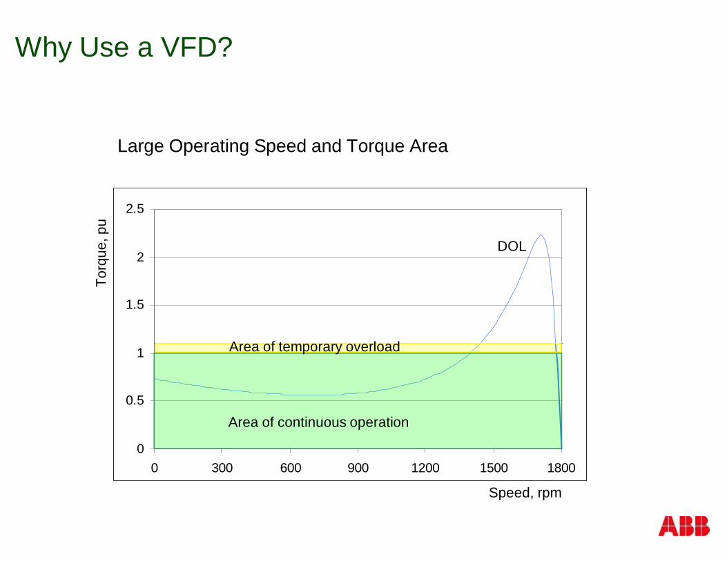
Why Use a VFD?
Large Operating Speed and Torque Area
0
0.5
1
1.5
2
2.5
0 300 600 900 1200 1500 1800
Torq
ue,p
u
Speed, rpm
Area of continuous operation
Area of temporary overload
DOL
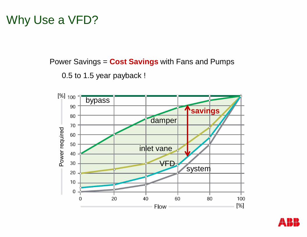
Why Use a VFD?
Power Savings = Cost Savings with Fans and Pumps
0.5 to 1.5 year payback !
bypass
damper
inlet vane
VFD system
savings
Why Use a VFD?
Adjustable speed to Optimize Process
Reduce production losses
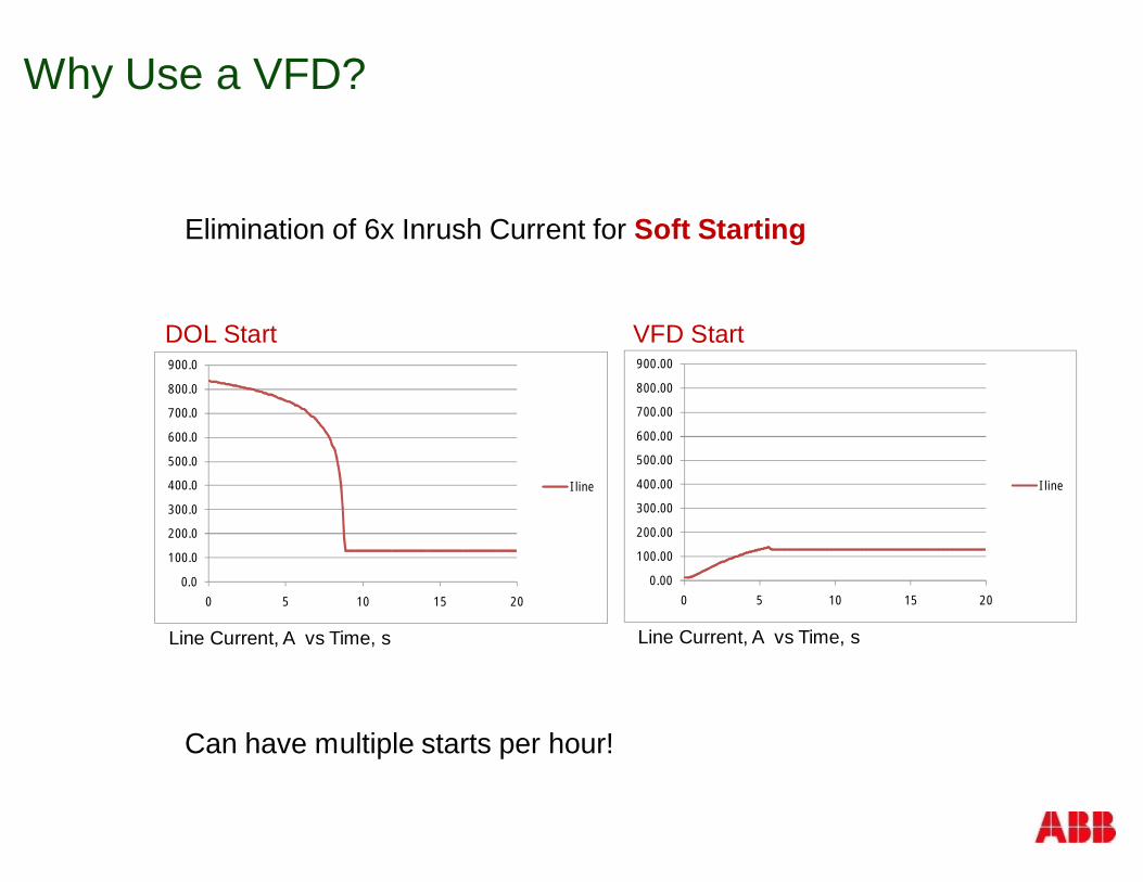
Why Use a VFD?
Elimination of 6x Inrush Current for Soft Starting
Can have multiple starts per hour!
Line Current, A vs Time, s
0.0
100.0
200.0
300.0
400.0
500.0
600.0
700.0
800.0
900.0
0 5 10 15 20
I line
Line Current, A vs Time, s
0.00
100.00
200.00
300.00
400.00
500.00
600.00
700.00
800.00
900.00
0 5 10 15 20
I line
DOL Start VFD Start
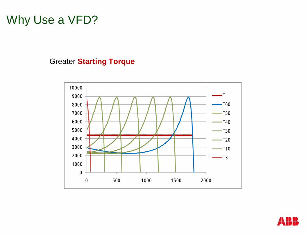
Why Use a VFD?
Greater Starting Torque
Torque vs Speed0
1000
2000
3000
4000
5000
6000
7000
8000
9000
10000
0 500 1000 1500 2000
T
T60
T50
T40
T30
T20
T10
T3
Why Use a VFD?
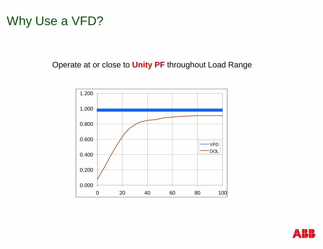
Operate at or close to Unity PF throughout Load Range
PF vs Load, %0.000
0.200
0.400
0.600
0.800
1.000
1.200
0 20 40 60 80 100
VFDDOL
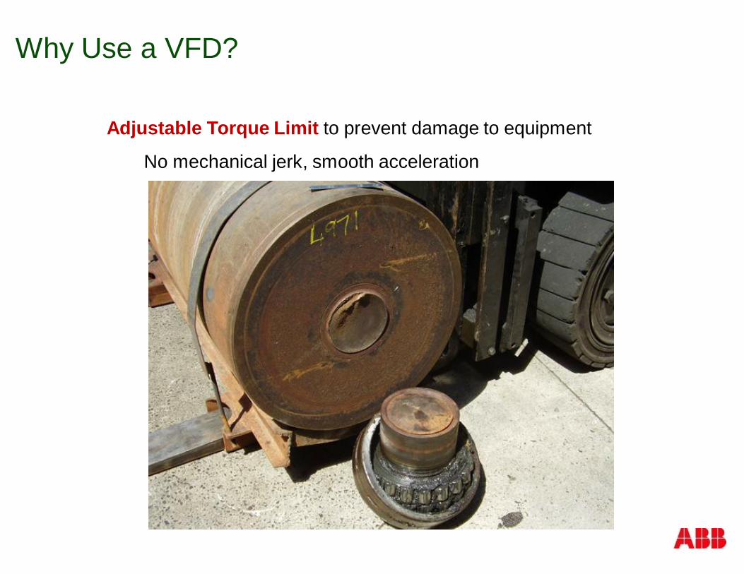
Why Use a VFD?
Adjustable Torque Limit to prevent damage to equipment
No mechanical jerk, smooth acceleration
What is LV and MV?

What is LV and MV?
© ABB Inc.July 24, 2014 | Slide 15
200V
690V
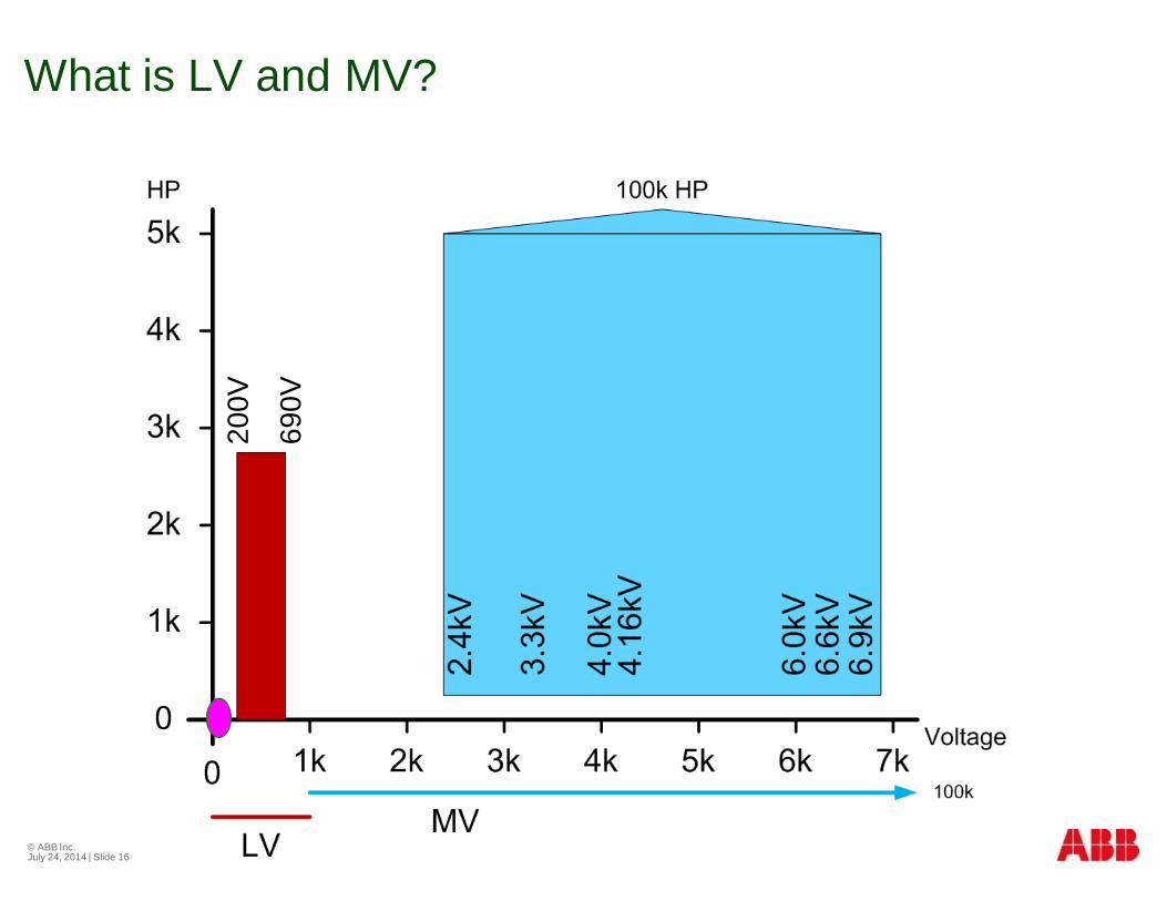
What is LV and MV?
© ABB Inc.July 24, 2014 | Slide 16
200V
690V
How do you change thespeed of an AC motor?
© ABB Inc.July 24, 2014 | Slide 18
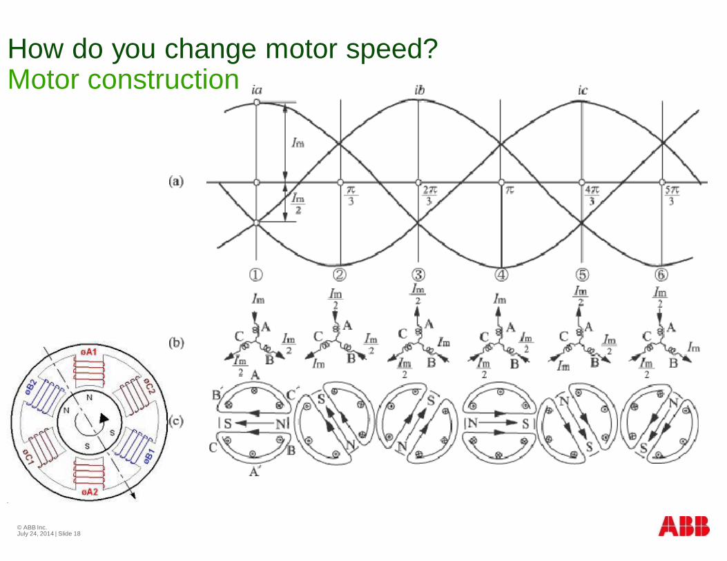
How do you change motor speed?Motor construction
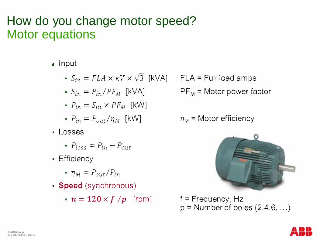
How do you change motor speed?Motor equations
§
© ABB GroupJuly 24, 2014 | Slide 19
How do you make variablefrequency AC?
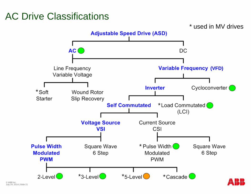
AC Drive Classifications
© ABB Inc.July 24, 2014 | Slide 21
* used in MV drives
*
***
*
*
(VFD)
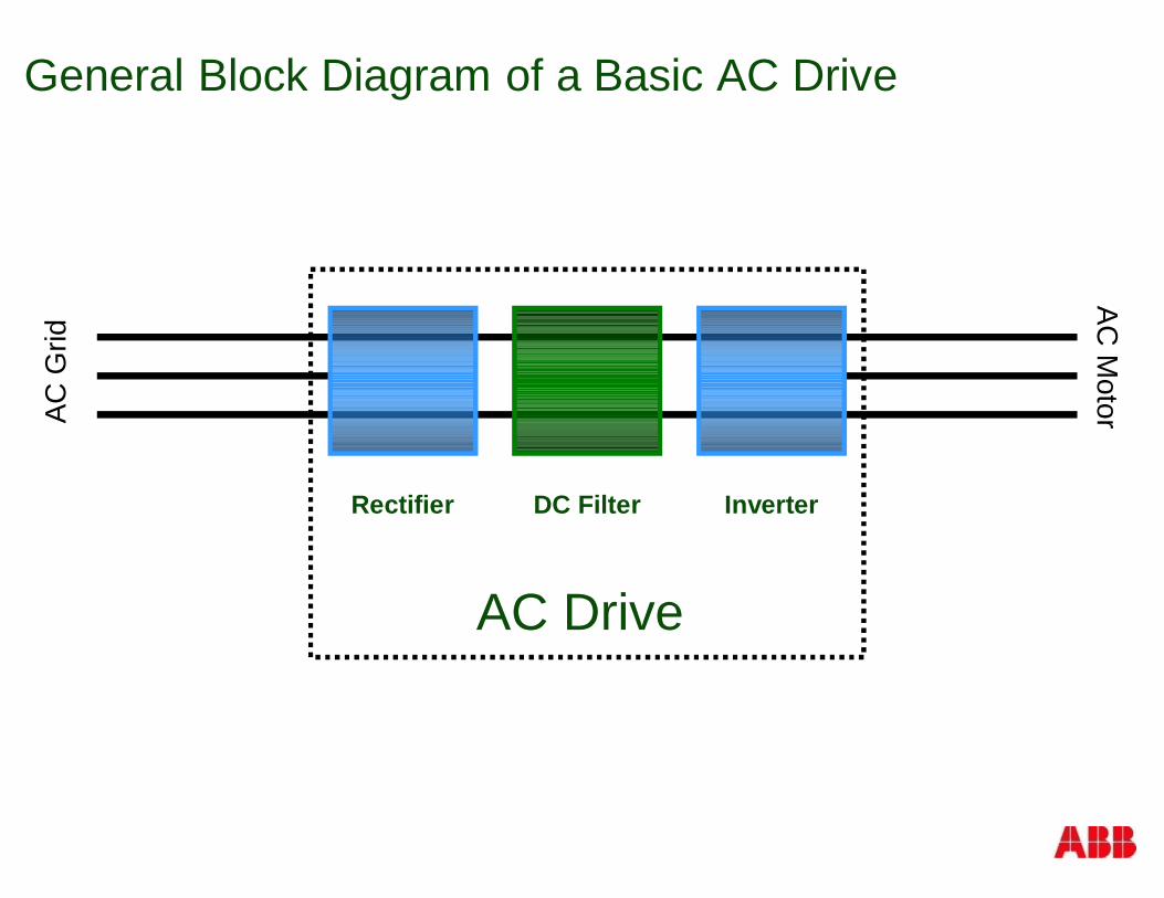
General Block Diagram of a Basic AC Drive
Rectifier DC Filter Inverter
ACG
ridAC
Motor
AC Drive
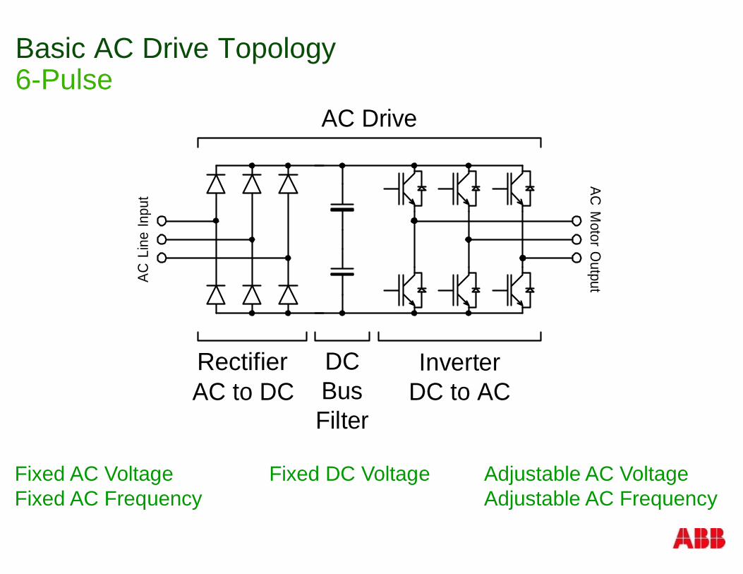
Basic AC Drive Topology6-Pulse
Fixed AC VoltageFixed AC Frequency
Adjustable AC VoltageAdjustable AC Frequency
Fixed DC Voltage
ConverterAC to DC
InverterDC to AC
DCBusFilter
AC DriveAC
MotorO
utputACLi
neIn
put
Rectifier
24
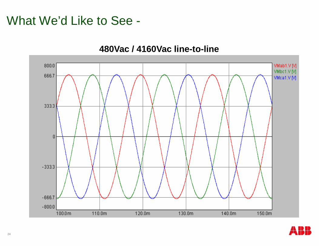
What We’d Like to See -
480Vac / 4160Vac line-to-line
25
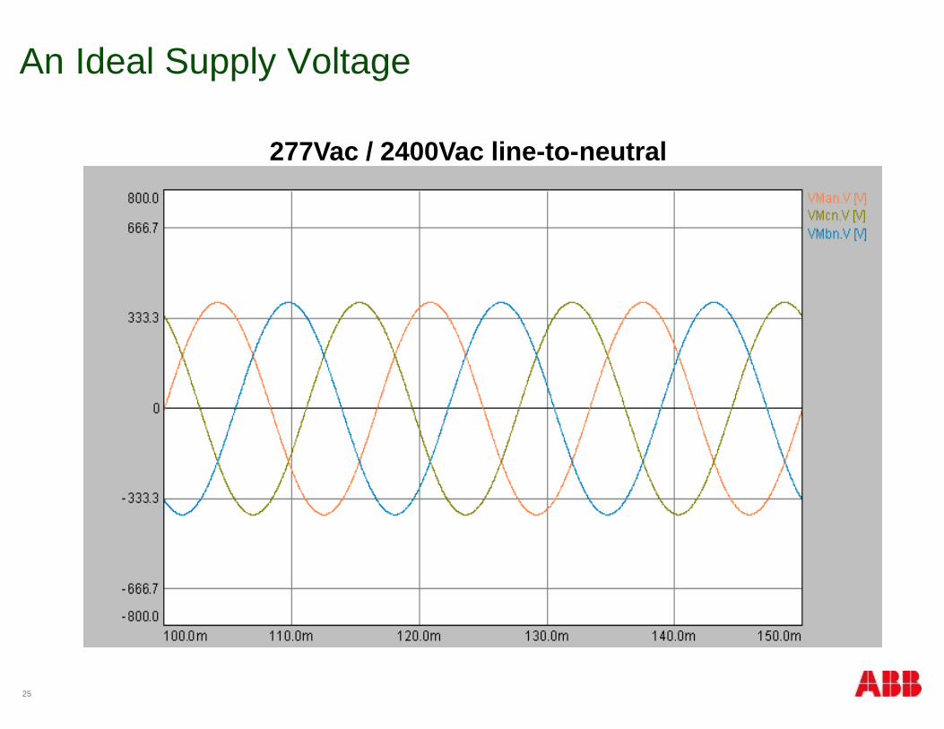
An Ideal Supply Voltage
277Vac / 2400Vac line-to-neutral
26
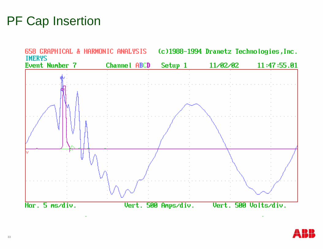
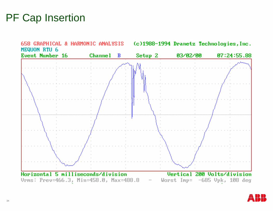
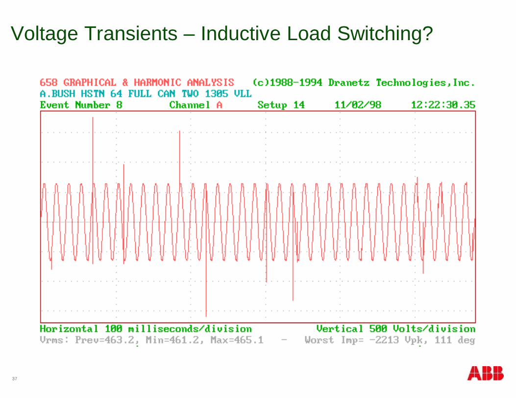
Common Power Quality Problems
§ Too High
§ Switching in PF caps
§ DC drive transients
§ Switching off inductive loads
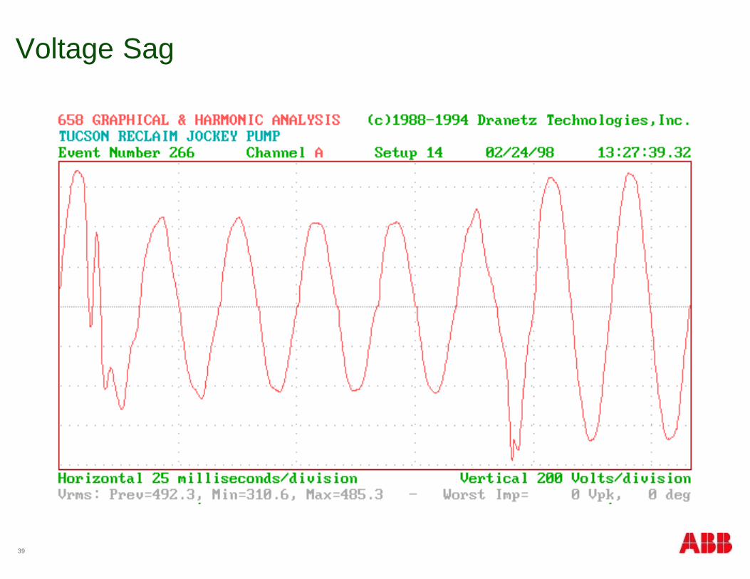
§ Too Low
§ Voltage sags
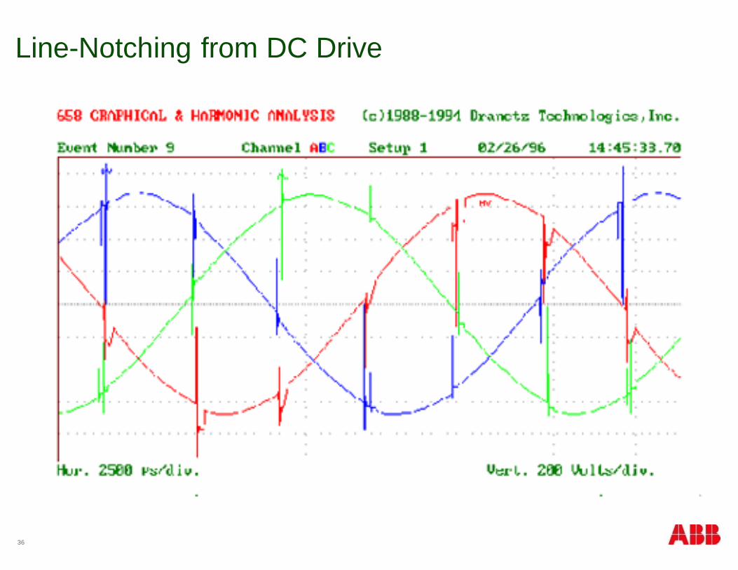
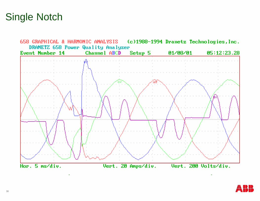
§ Voltage notches
§ Voltage flat-topping
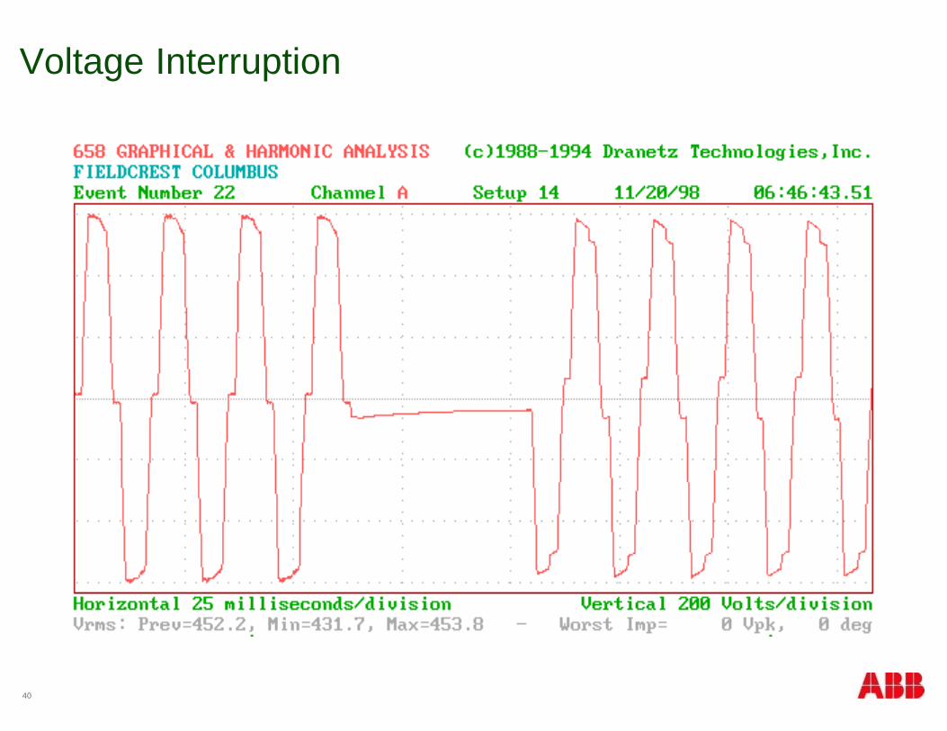
§ Nothing’s There
§ Voltage interruptions
27
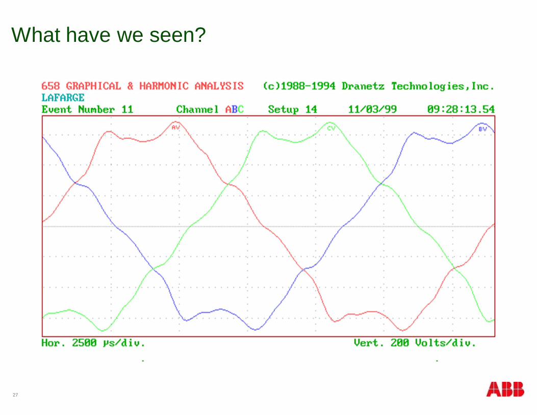
What have we seen?
28
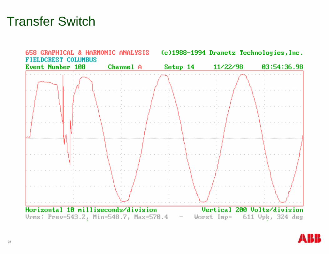
Transfer Switch
29
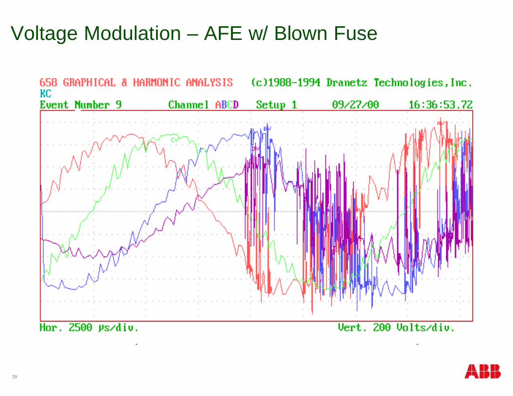
Voltage Modulation – AFE w/ Blown Fuse
30
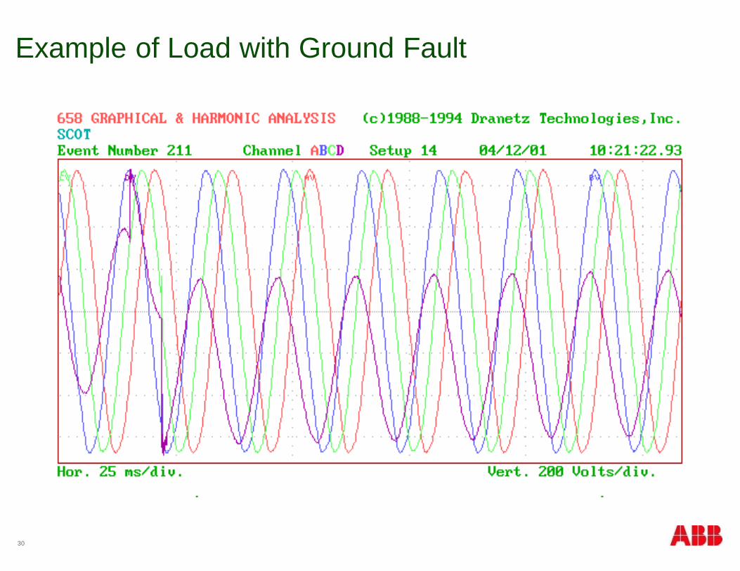
Example of Load with Ground Fault
31
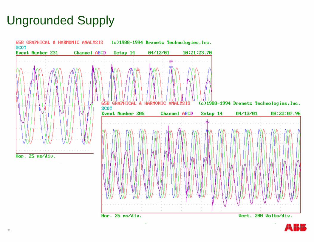
Ungrounded Supply
32
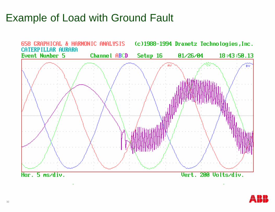
Example of Load with Ground Fault
33
PF Cap Insertion
34
PF Cap Insertion
35
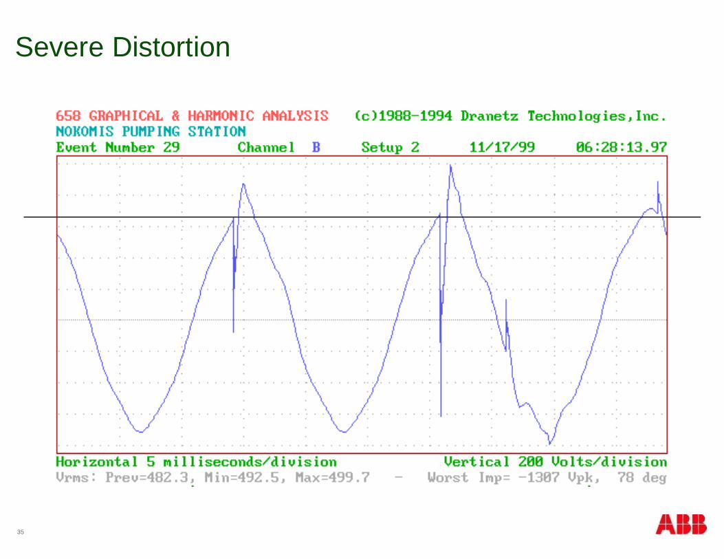
Severe Distortion
36
Line-Notching from DC Drive
37
Voltage Transients – Inductive Load Switching?
38
Single Notch
39
Voltage Sag
40
Voltage Interruption
41
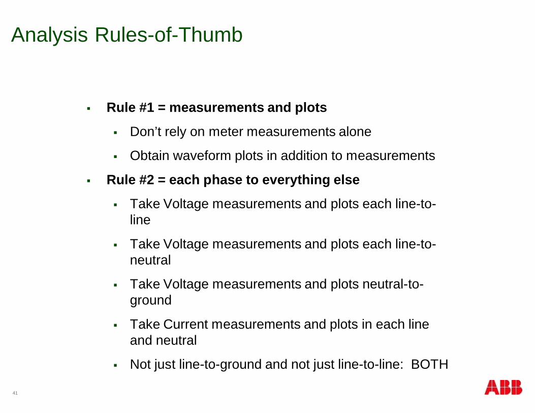
Analysis Rules-of-Thumb
§ Rule #1 = measurements and plots
§ Don’t rely on meter measurements alone
§ Obtain waveform plots in addition to measurements
§ Rule #2 = each phase to everything else
§ Take Voltage measurements and plots each line-to-line
§ Take Voltage measurements and plots each line-to-neutral
§ Take Voltage measurements and plots neutral-to-ground
§ Take Current measurements and plots in each lineand neutral
§ Not just line-to-ground and not just line-to-line: BOTH
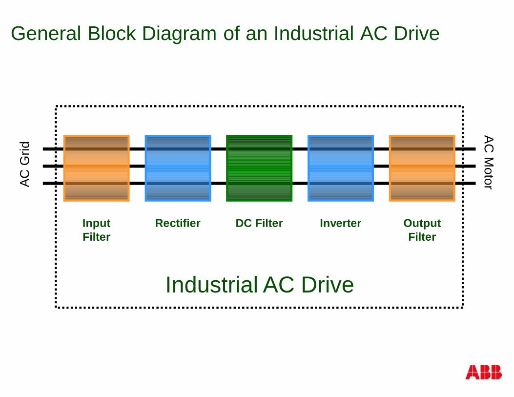
General Block Diagram of an Industrial AC Drive
InputFilter
Rectifier DC Filter Inverter OutputFilter
ACG
ridAC
Motor
Industrial AC Drive
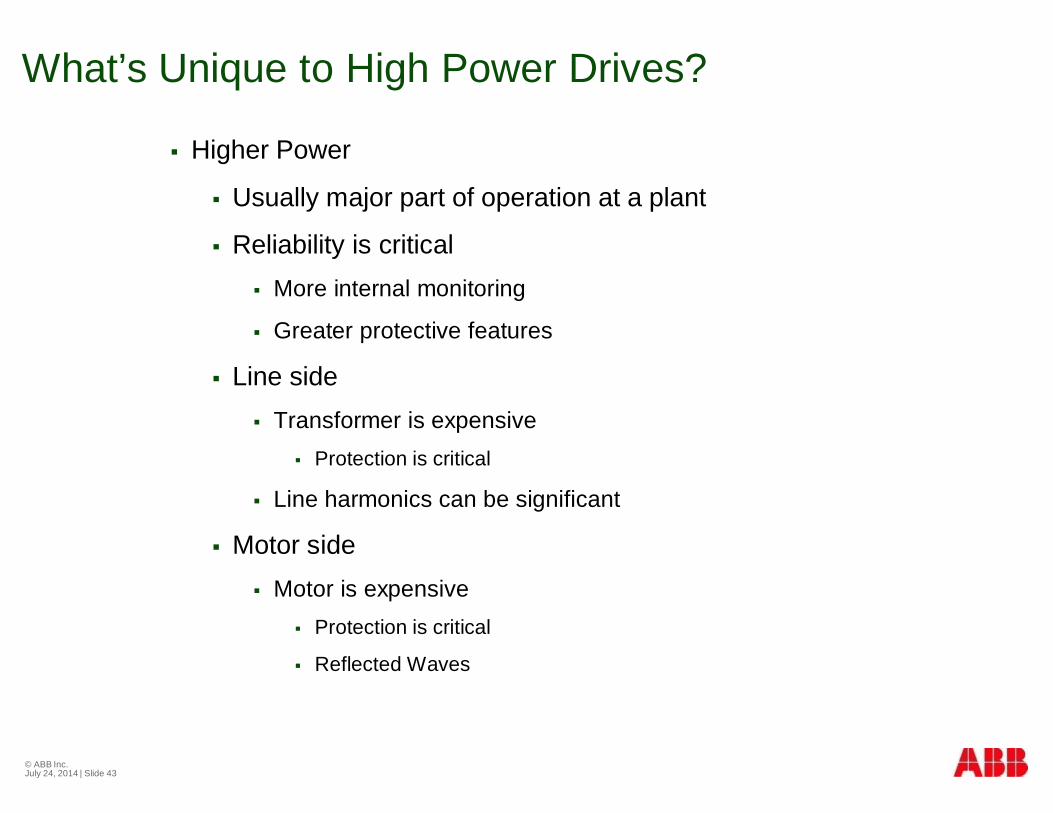
What’s Unique to High Power Drives?
§ Higher Power
§ Usually major part of operation at a plant
§ Reliability is critical§ More internal monitoring
§ Greater protective features
§ Line side§ Transformer is expensive
§ Protection is critical
§ Line harmonics can be significant
§ Motor side§ Motor is expensive
§ Protection is critical
§ Reflected Waves
© ABB Inc.July 24, 2014 | Slide 43
Line Side Requirements
§ Harmonics
§ Power Factor
§ Grounding Configuration

What are Harmonics?
Rfund.V =...
0
0
40.00m
40.00m
10.00m
10.00m
20.00m
20.00m
30.00m
30.00m
-150.0 -150.0
150.0
0 0
-100.0 -100.0
-50.0 -50.0
50.0 50.0
100.0 100.0
A sinusoidal waveform has no harmonics
This is an example of a linear load
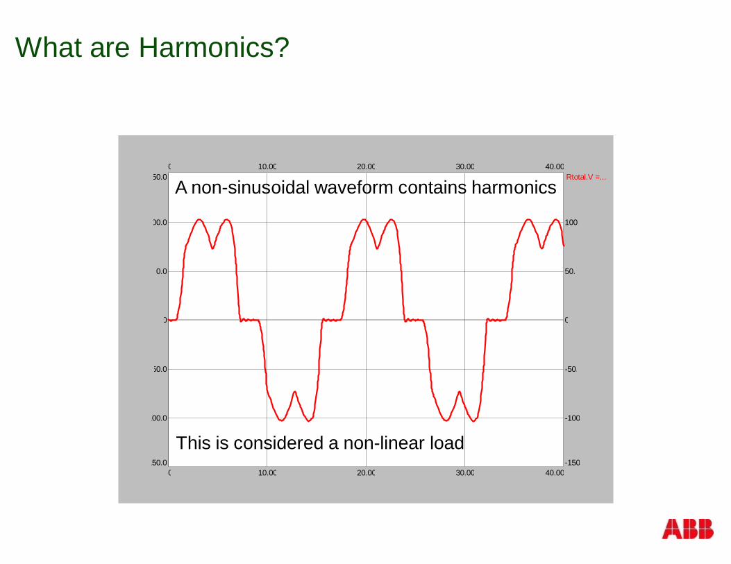
What are Harmonics?
Rtotal.V =...
0
0
40.00m
40.00m
10.00m
10.00m
20.00m
20.00m
30.00m
30.00m
-150.0 -150.0
150.0
0 0
-100.0 -100.0
-50.0 -50.0
50.0 50.0
100.0 100.0
A non-sinusoidal waveform contains harmonics
This is considered a non-linear load
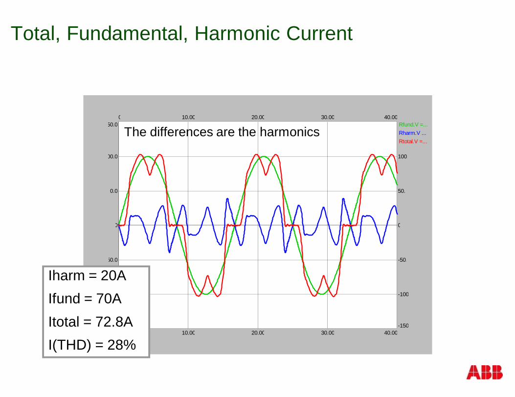
Total, Fundamental, Harmonic Current
Rfund.V =...Rharm.V ...Rtotal.V =...
0
0
40.00m
40.00m
10.00m
10.00m
20.00m
20.00m
30.00m
30.00m
-150.0 -150.0
150.0
0 0
-100.0 -100.0
-50.0 -50.0
50.0 50.0
100.0 100.0
Iharm = 20AIfund = 70AItotal = 72.8AI(THD) = 28%
The differences are the harmonics
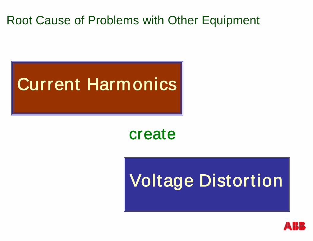
Current Harmonics
create
Voltage Distortion
Root Cause of Problems with Other Equipment
49
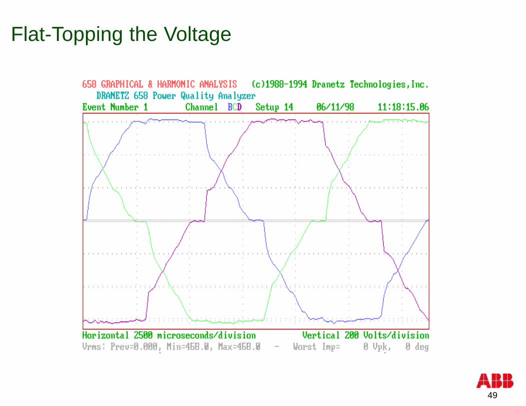
Flat-Topping the Voltage
50
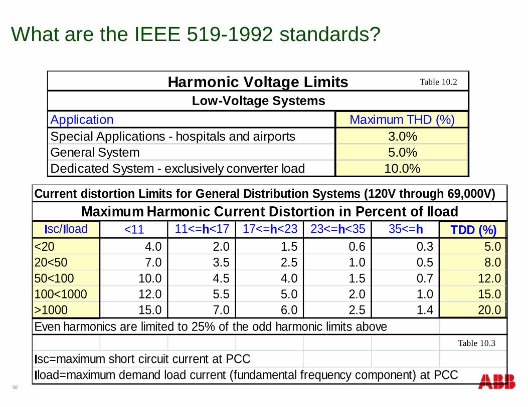
What are the IEEE 519-1992 standards?
Application Maximum THD (%)Special Applications - hospitals and airports 3.0%General System 5.0%Dedicated System - exclusively converter load 10.0%
Harmonic Voltage LimitsLow-Voltage Systems
Table 10.2
Table 10.3
Current distortion Limits for General Distribution Systems (120V through 69,000V)
Isc/Iload <11 11<=h<17 17<=h<23 23<=h<35 35<=h TDD (%)<20 4.0 2.0 1.5 0.6 0.3 5.020<50 7.0 3.5 2.5 1.0 0.5 8.050<100 10.0 4.5 4.0 1.5 0.7 12.0100<1000 12.0 5.5 5.0 2.0 1.0 15.0>1000 15.0 7.0 6.0 2.5 1.4 20.0Even harmonics are limited to 25% of the odd harmonic limits above
Isc=maximum short circuit current at PCCIload=maximum demand load current (fundamental frequency component) at PCC
Maximum Harmonic Current Distortion in Percent of Iload
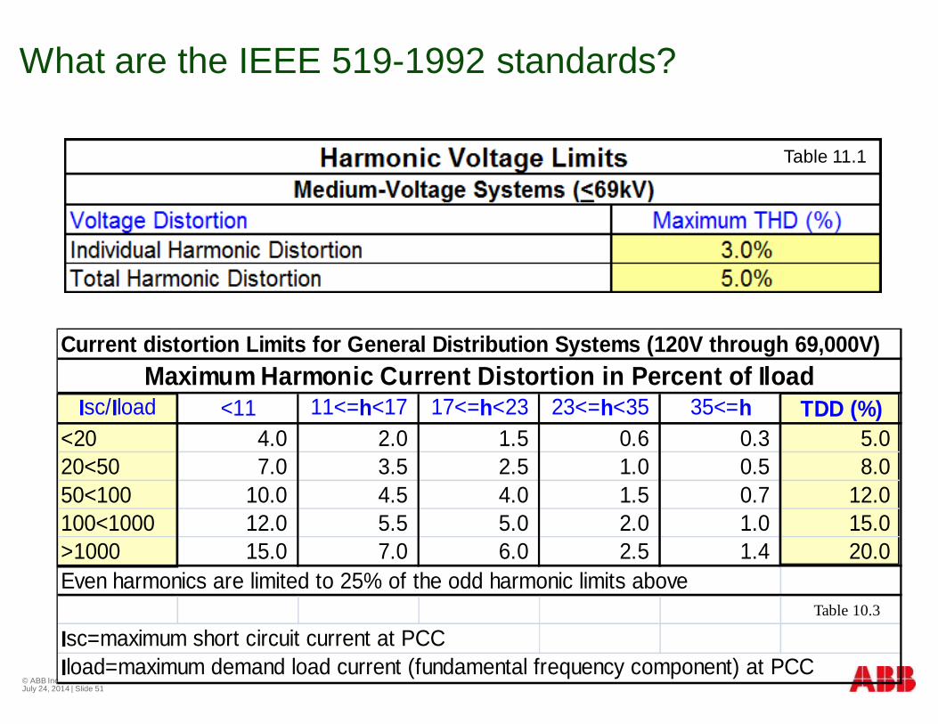
What are the IEEE 519-1992 standards?
© ABB Inc.July 24, 2014 | Slide 51
Table 11.1
Table 10.3
Current distortion Limits for General Distribution Systems (120V through 69,000V)
Isc/Iload <11 11<=h<17 17<=h<23 23<=h<35 35<=h TDD (%)<20 4.0 2.0 1.5 0.6 0.3 5.020<50 7.0 3.5 2.5 1.0 0.5 8.050<100 10.0 4.5 4.0 1.5 0.7 12.0100<1000 12.0 5.5 5.0 2.0 1.0 15.0>1000 15.0 7.0 6.0 2.5 1.4 20.0Even harmonics are limited to 25% of the odd harmonic limits above
Isc=maximum short circuit current at PCCIload=maximum demand load current (fundamental frequency component) at PCC
Maximum Harmonic Current Distortion in Percent of Iload
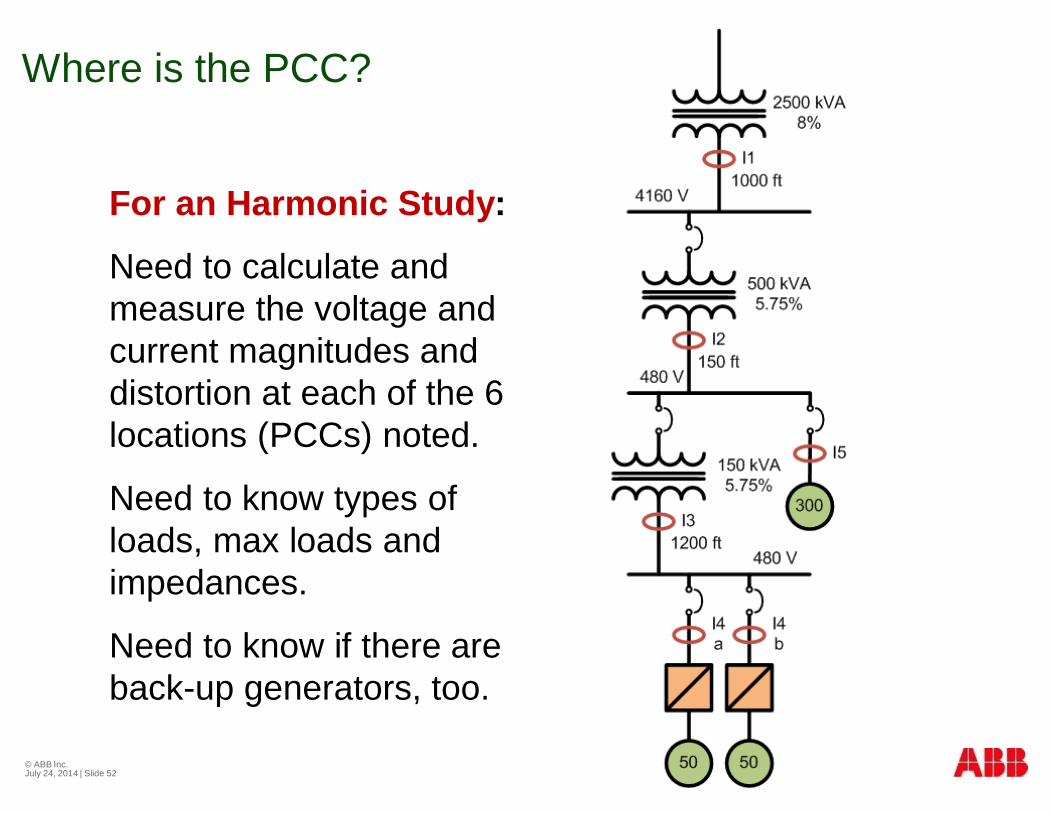
Where is the PCC?
© ABB Inc.July 24, 2014 | Slide 52
For an Harmonic Study:
Need to calculate andmeasure the voltage andcurrent magnitudes anddistortion at each of the 6locations (PCCs) noted.
Need to know types ofloads, max loads andimpedances.
Need to know if there areback-up generators, too.
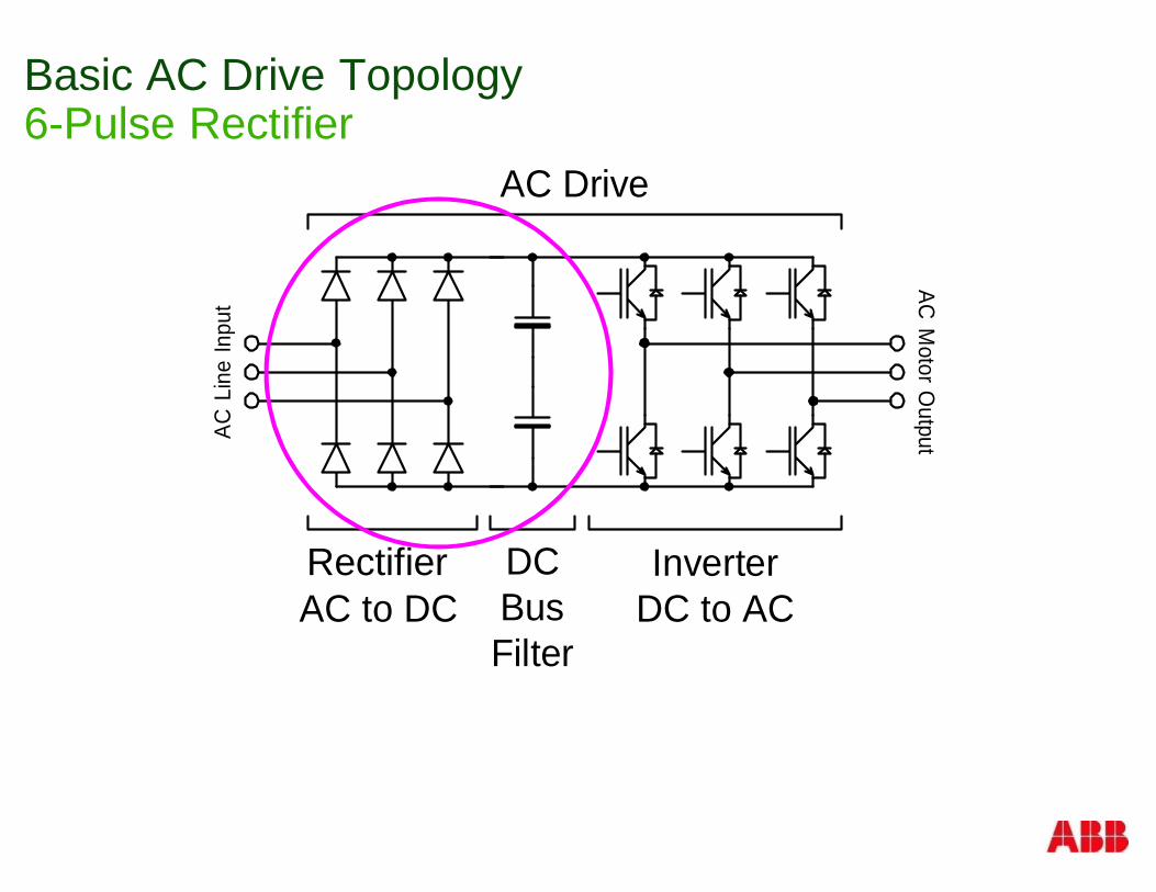
Basic AC Drive Topology6-Pulse Rectifier
ConverterAC to DC
InverterDC to AC
DCBusFilter
AC DriveAC
MotorO
utputACLi
neIn
put
Rectifier
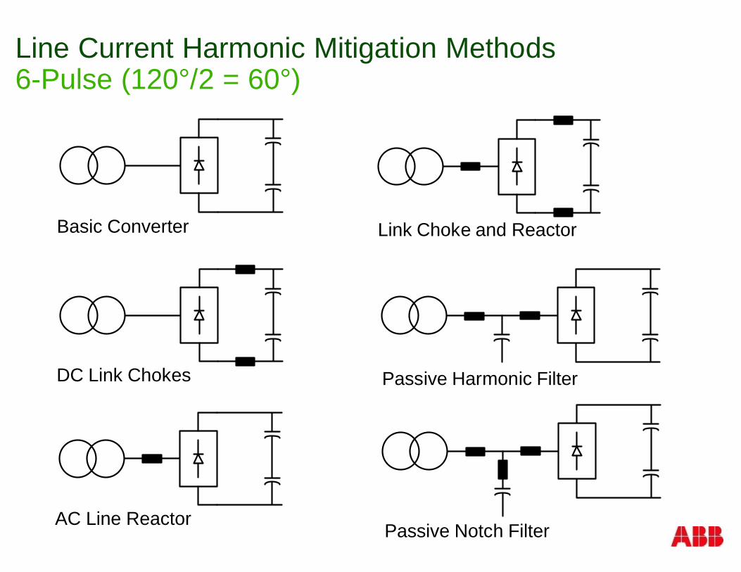
Line Current Harmonic Mitigation Methods6-Pulse (120°/2 = 60°)
Basic Converter
DC Link Chokes
AC Line Reactor
Link Choke and Reactor
Passive Harmonic Filter
Passive Notch Filter
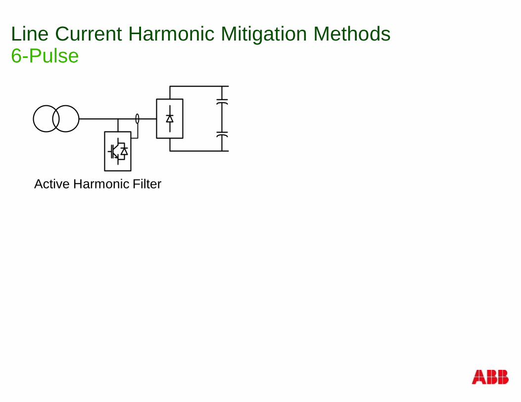
Line Current Harmonic Mitigation Methods6-Pulse
Active Harmonic Filter
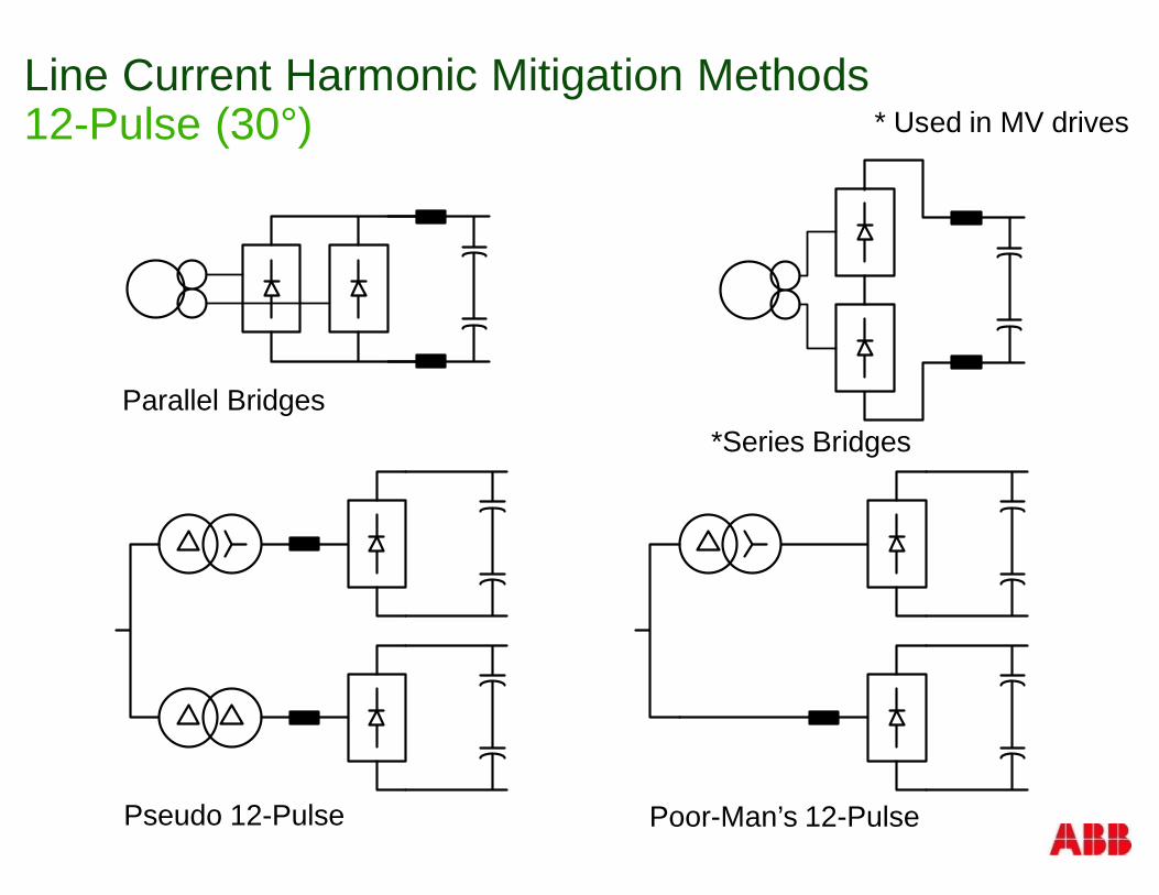
Line Current Harmonic Mitigation Methods12-Pulse (30°)
Parallel Bridges*Series Bridges
Pseudo 12-Pulse Poor-Man’s 12-Pulse
* Used in MV drives
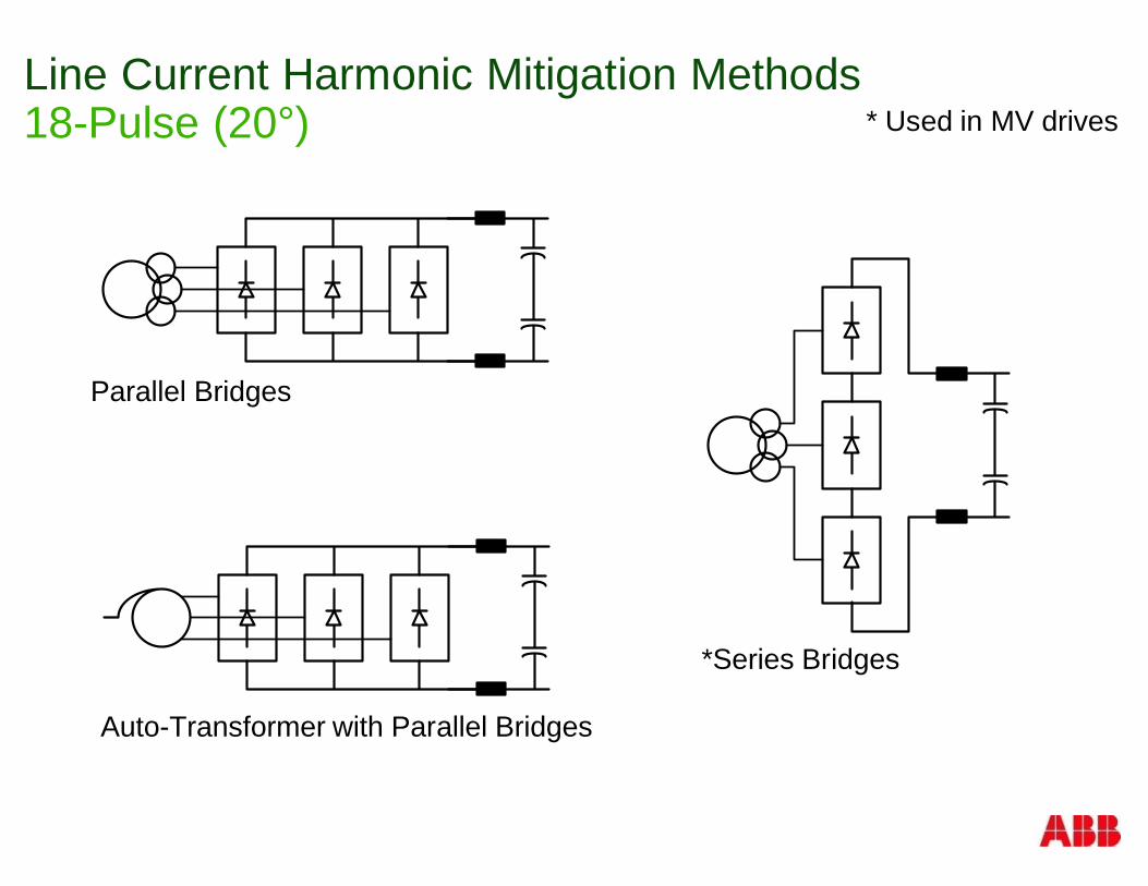
Line Current Harmonic Mitigation Methods18-Pulse (20°)
Parallel Bridges
*Series Bridges
Auto-Transformer with Parallel Bridges
* Used in MV drives
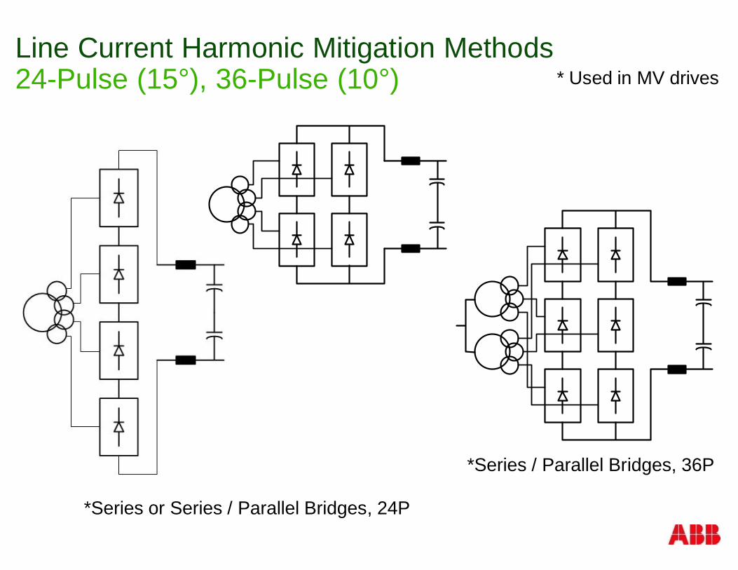
Line Current Harmonic Mitigation Methods24-Pulse (15°), 36-Pulse (10°)
*Series or Series / Parallel Bridges, 24P
*Series / Parallel Bridges, 36P
* Used in MV drives
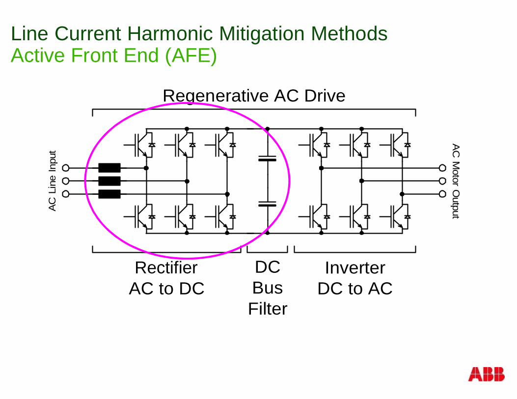
Line Current Harmonic Mitigation MethodsActive Front End (AFE)
AC
Line
Inpu
t
ConverterAC to DC
InverterDC to AC
DCBusFilter
Regenerative AC Drive
AC
Motor
Output
Rectifier
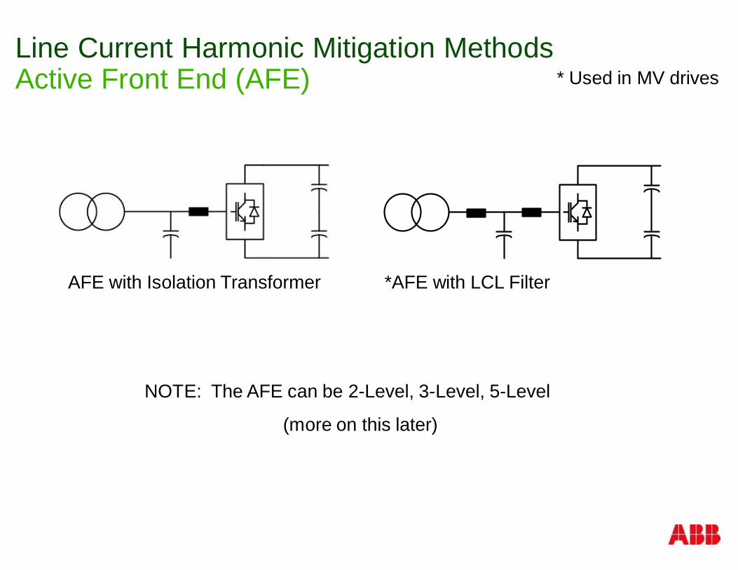
Line Current Harmonic Mitigation MethodsActive Front End (AFE)
AFE with Isolation Transformer *AFE with LCL Filter
NOTE: The AFE can be 2-Level, 3-Level, 5-Level
* Used in MV drives
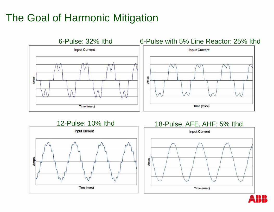
6-Pulse: 32% Ithd 6-Pulse with 5% Line Reactor: 25% Ithd
12-Pulse: 10% Ithd 18-Pulse, AFE, AHF: 5% Ithd
The Goal of Harmonic Mitigation
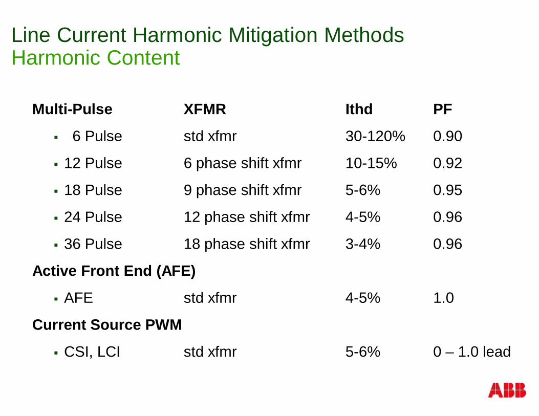
Line Current Harmonic Mitigation MethodsHarmonic Content
Multi-Pulse XFMR Ithd PF
§ 6 Pulse std xfmr 30-120% 0.90
§ 12 Pulse 6 phase shift xfmr 10-15% 0.92
§ 18 Pulse 9 phase shift xfmr 5-6% 0.95
§ 24 Pulse 12 phase shift xfmr 4-5% 0.96
§ 36 Pulse 18 phase shift xfmr 3-4% 0.96
Active Front End (AFE)
§ AFE std xfmr 4-5% 1.0
Current Source PWM
§ CSI, LCI std xfmr 5-6% 0 – 1.0 lead
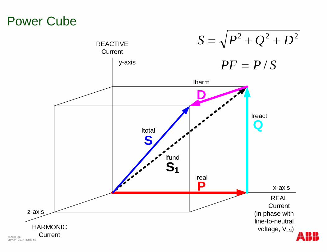
Power Cube
© ABB Inc.July 24, 2014 | Slide 63
HARMONICCurrent
Ireact
Ireal
Ifund
Itotal
Iharm
(in phase withline-to-neutral voltage, VLN)
REACTIVECurrent
Q
PS1
S
D
x-axis
y-axis
z-axis
REALCurrent
222 DQPS ++=
SPPF /=
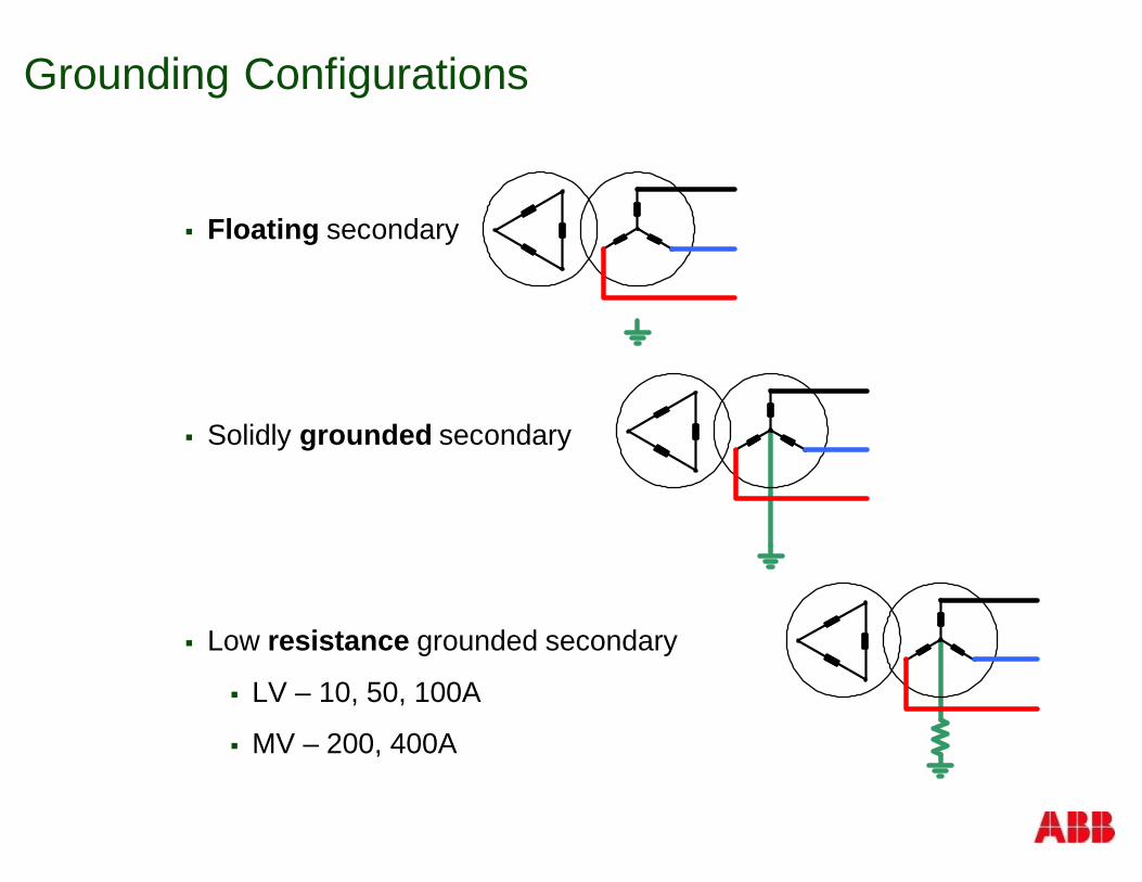
Grounding Configurations
§ Floating secondary
§ Solidly grounded secondary
§ Low resistance grounded secondary
§ LV – 10, 50, 100A
§ MV – 200, 400A
Motor Side Challenges
§ NEMA MG-1
§ Topologies
§ Reflected Wave
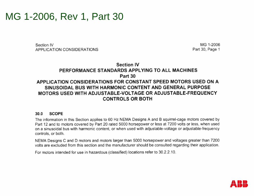
MG 1-2006, Rev 1, Part 30
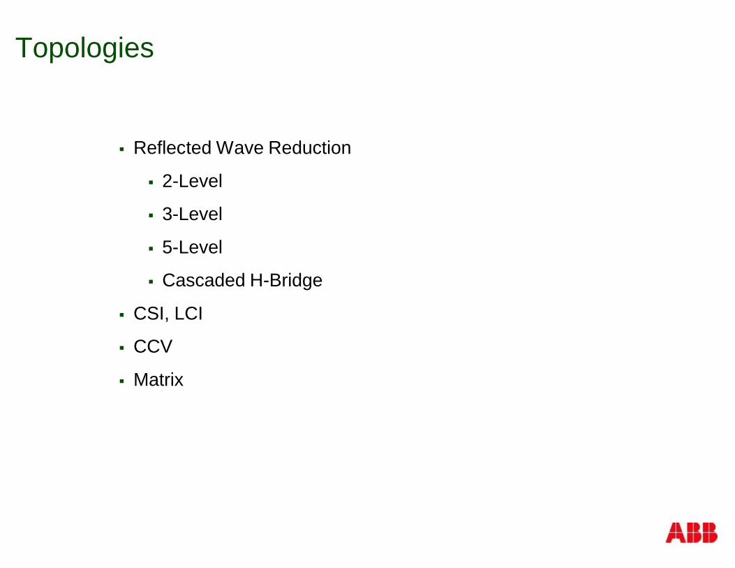
Topologies
§ Reflected Wave Reduction
§ 2-Level
§ 3-Level
§ 5-Level
§ Cascaded H-Bridge
§ CSI, LCI
§ CCV
§ Matrix
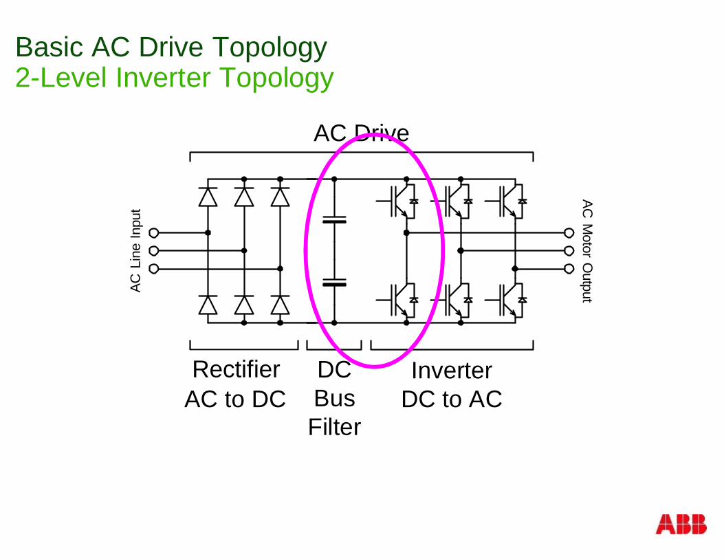
Basic AC Drive Topology2-Level Inverter Topology
ConverterAC to DC
InverterDC to AC
DCBusFilter
AC DriveAC
Motor
OutputAC
Line
Inpu
t
Rectifier
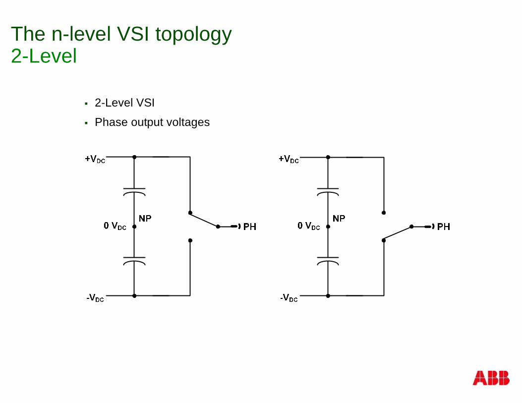
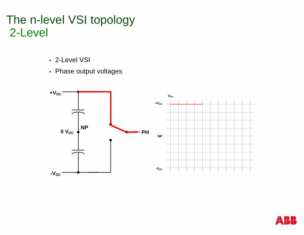
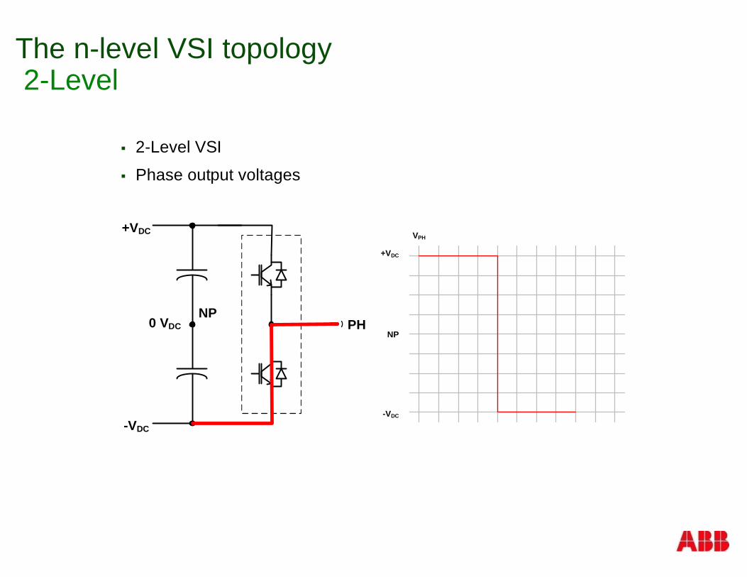
The n-level VSI topology2-Level
§ 2-Level VSI
§ Phase output voltages
The n-level VSI topology2-Level
§ 2-Level VSI
§ Phase output voltages
+VDC
-VDC
0 VDC PHNP
+VDC
NP
-VDC
VPH
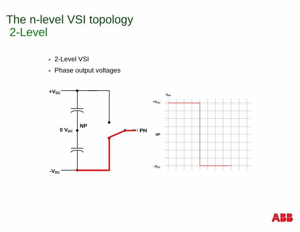
The n-level VSI topology2-Level
§ 2-Level VSI
§ Phase output voltages
+VDC
-VDC
0 VDC PHNP
+VDC
NP
-VDC
VPH
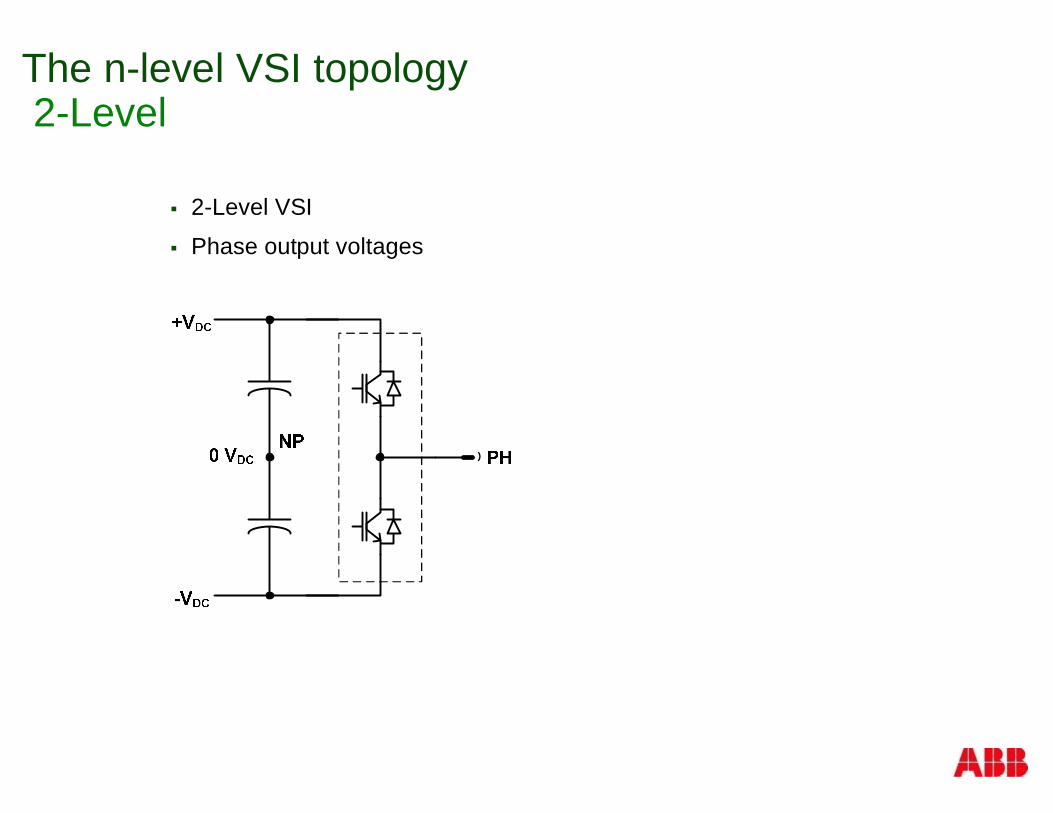
The n-level VSI topology2-Level
§ 2-Level VSI
§ Phase output voltages
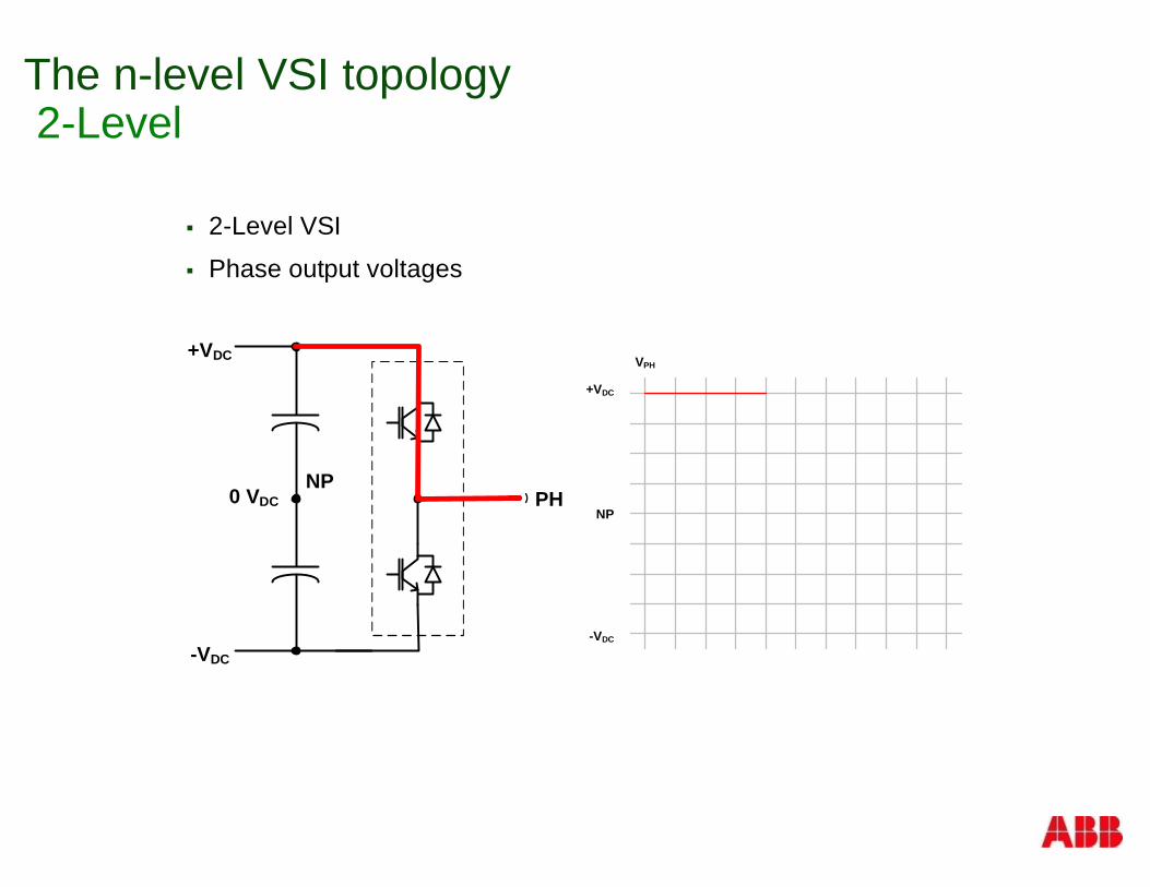
The n-level VSI topology2-Level
§ 2-Level VSI
§ Phase output voltages
+VDC
NP
-VDC
VPH+VDC
-VDC
0 VDC PHNP
The n-level VSI topology2-Level
§ 2-Level VSI
§ Phase output voltages
+VDC
NP
-VDC
VPH+VDC
-VDC
0 VDC PHNP
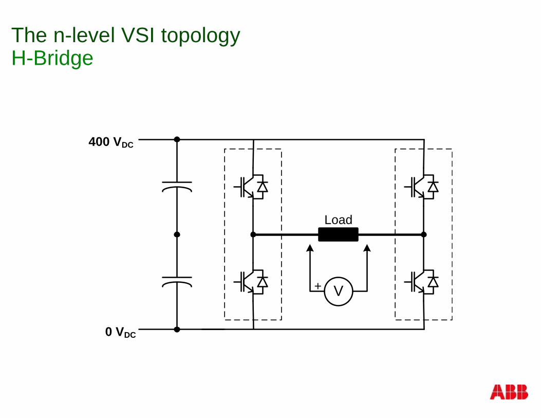
The n-level VSI topologyH-Bridge
V+
Load
400 VDC
0 VDC
The n-level VSI topologyH-Bridge
V+
Load
400 VDC
0 VDC
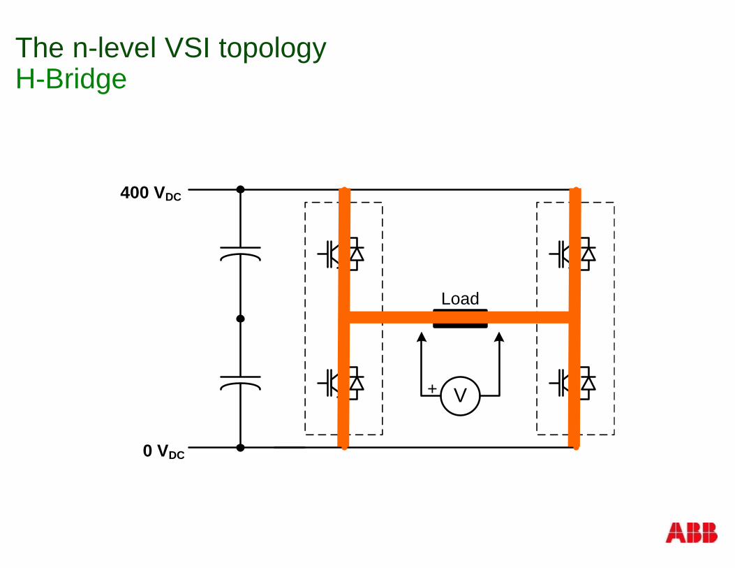
The n-level VSI topologyH-Bridge
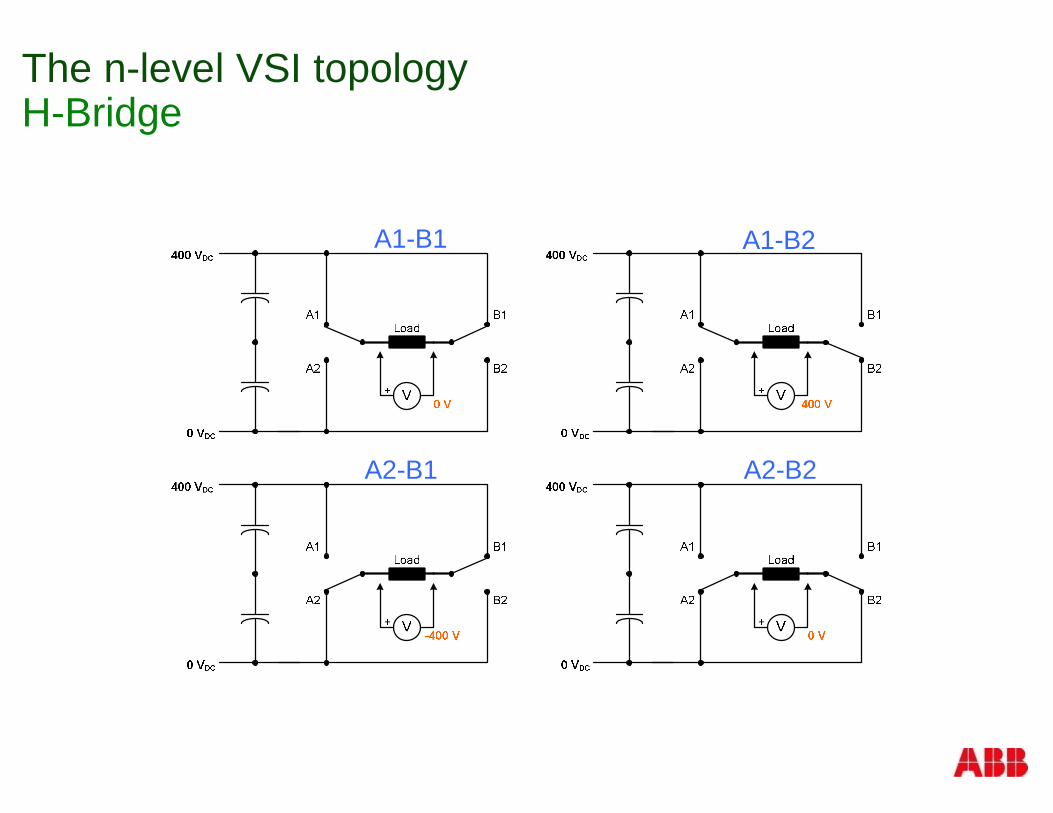
The n-level VSI topologyH-Bridge
A1-B1 A1-B2
A2-B2A2-B1
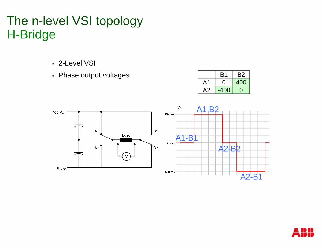
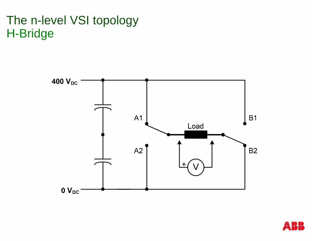
The n-level VSI topologyH-Bridge
§ 2-Level VSI
§ Phase output voltages
A1-B1
A1-B2
A2-B2
A2-B1
B1 B2A1 0 400A2 -400 0
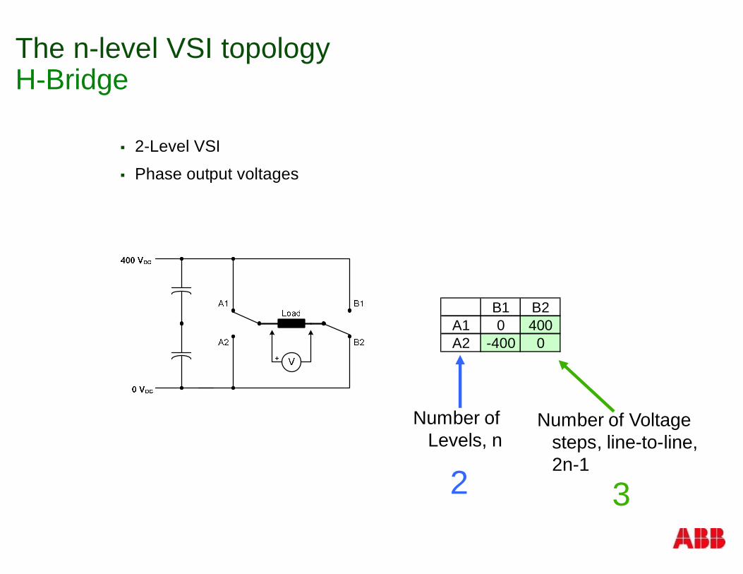
The n-level VSI topologyH-Bridge
§ 2-Level VSI
§ Phase output voltages
Number ofLevels, n
B1 B2A1 0 400A2 -400 0
Number of Voltagesteps, line-to-line,2n-1
2 3
-8k
8k
-6k
-4k
-2k
0
2k
4k
6k
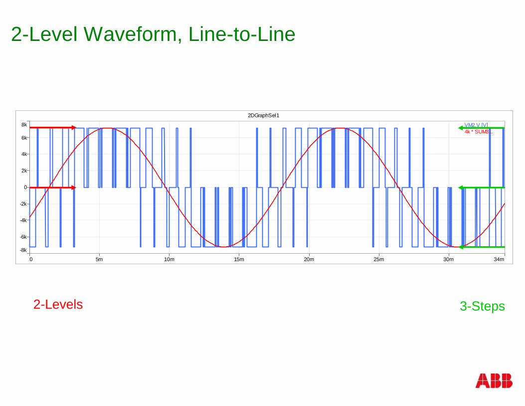
0 34m5m 10m 15m 20m 25m 30m
2DGraphSel1
VM2.V [V] 4k * SUM3...
2-Level Waveform, Line-to-Line
2-Levels 3-Steps

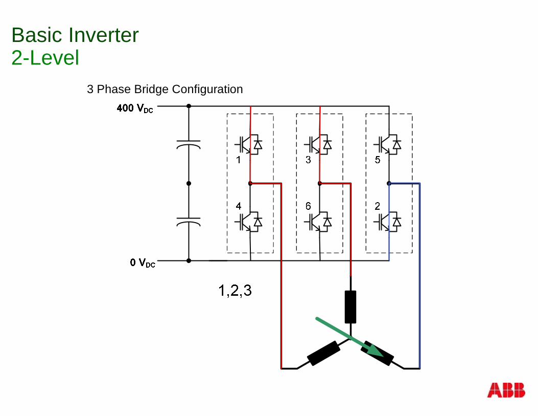
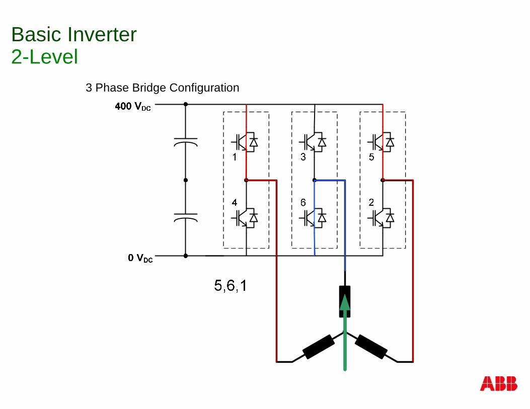
Basic Inverter2-Level
3 Phase Bridge Configuration
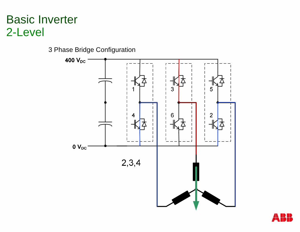
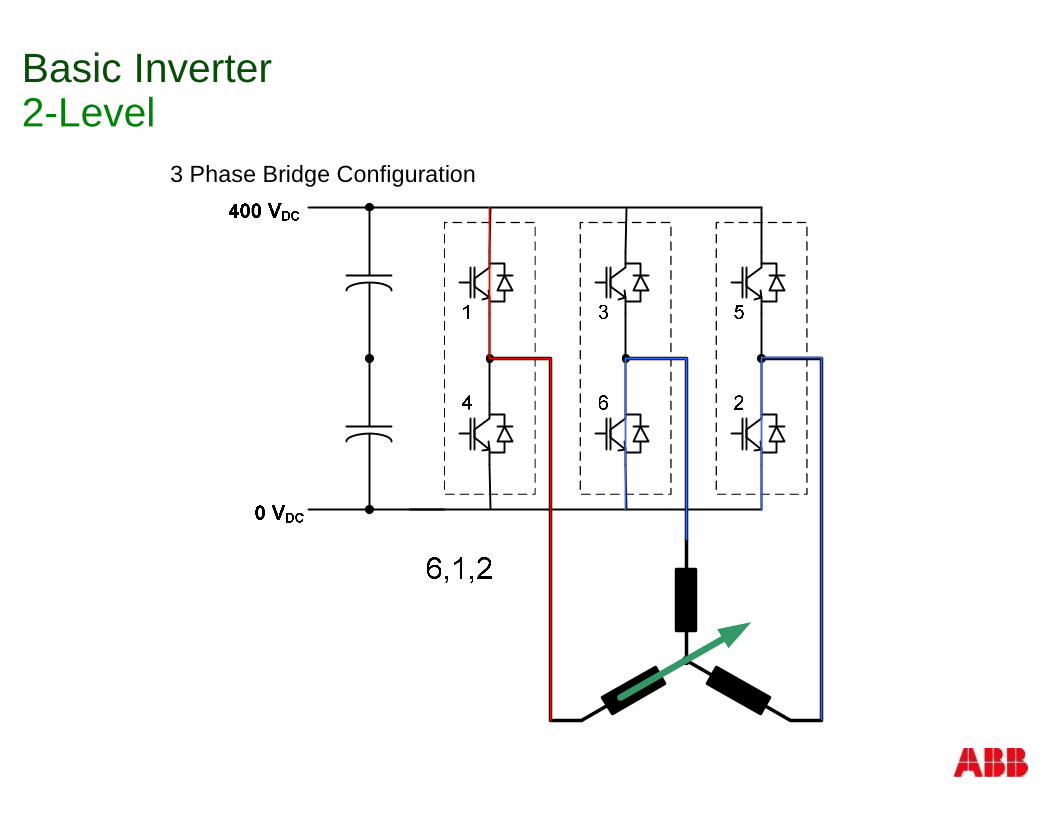
Basic Inverter2-Level
3 Phase Bridge Configuration
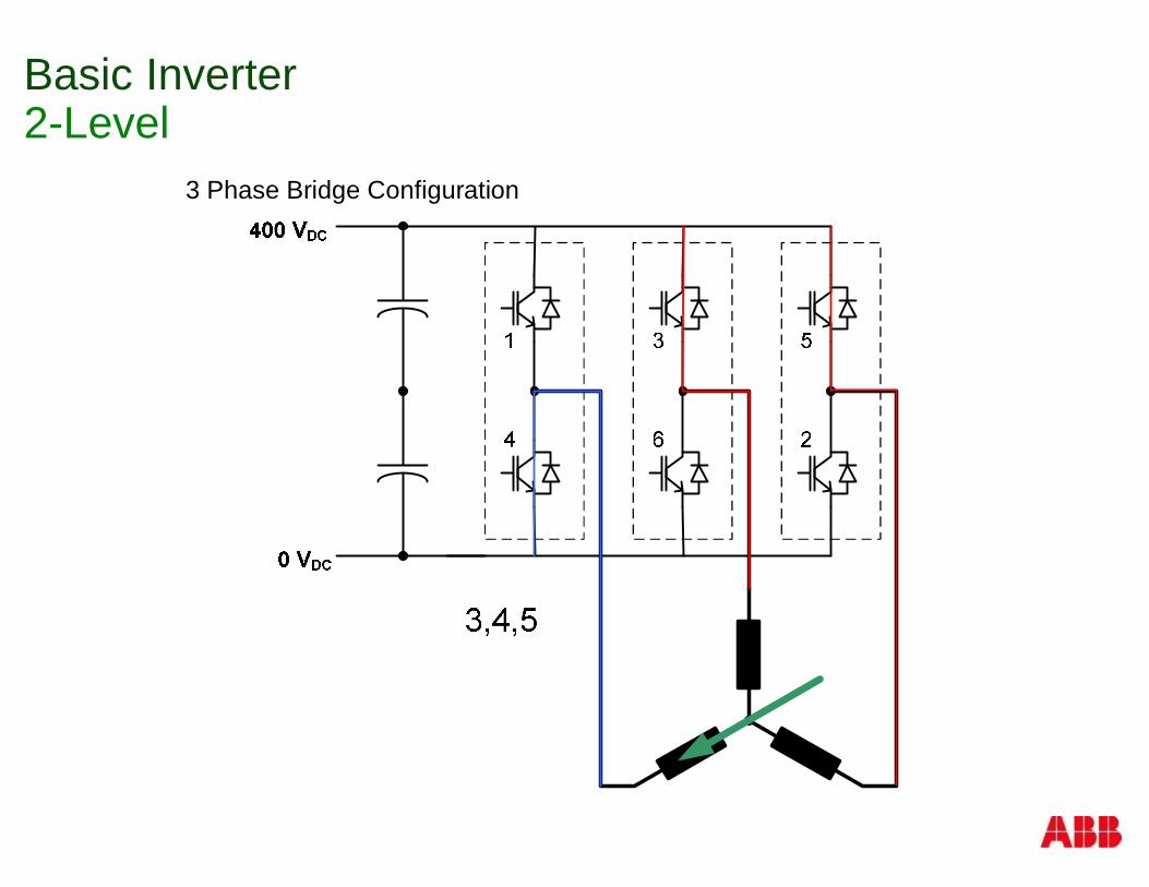
Basic Inverter2-Level
3 Phase Bridge Configuration
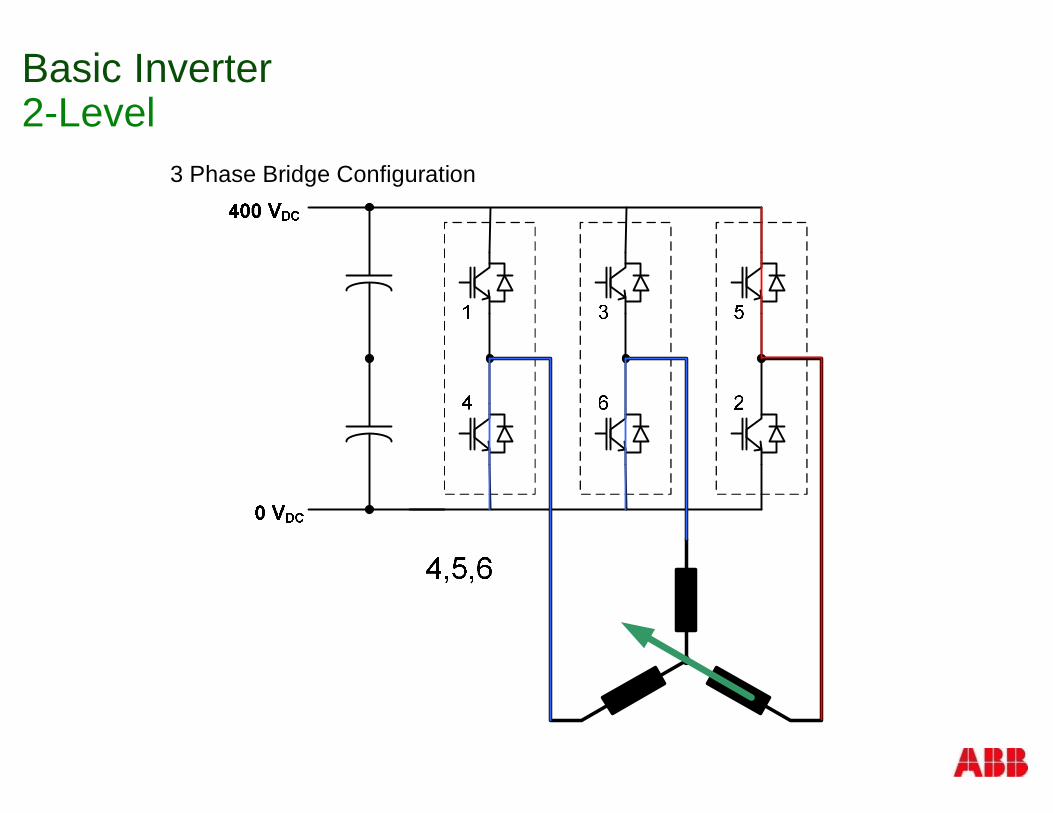
Basic Inverter2-Level
3 Phase Bridge Configuration
Basic Inverter2-Level
3 Phase Bridge Configuration
Basic Inverter2-Level
3 Phase Bridge Configuration
Basic Inverter2-Level
3 Phase Bridge Configuration

Basic Inverter2-Level
3 Phase Bridge Configuration
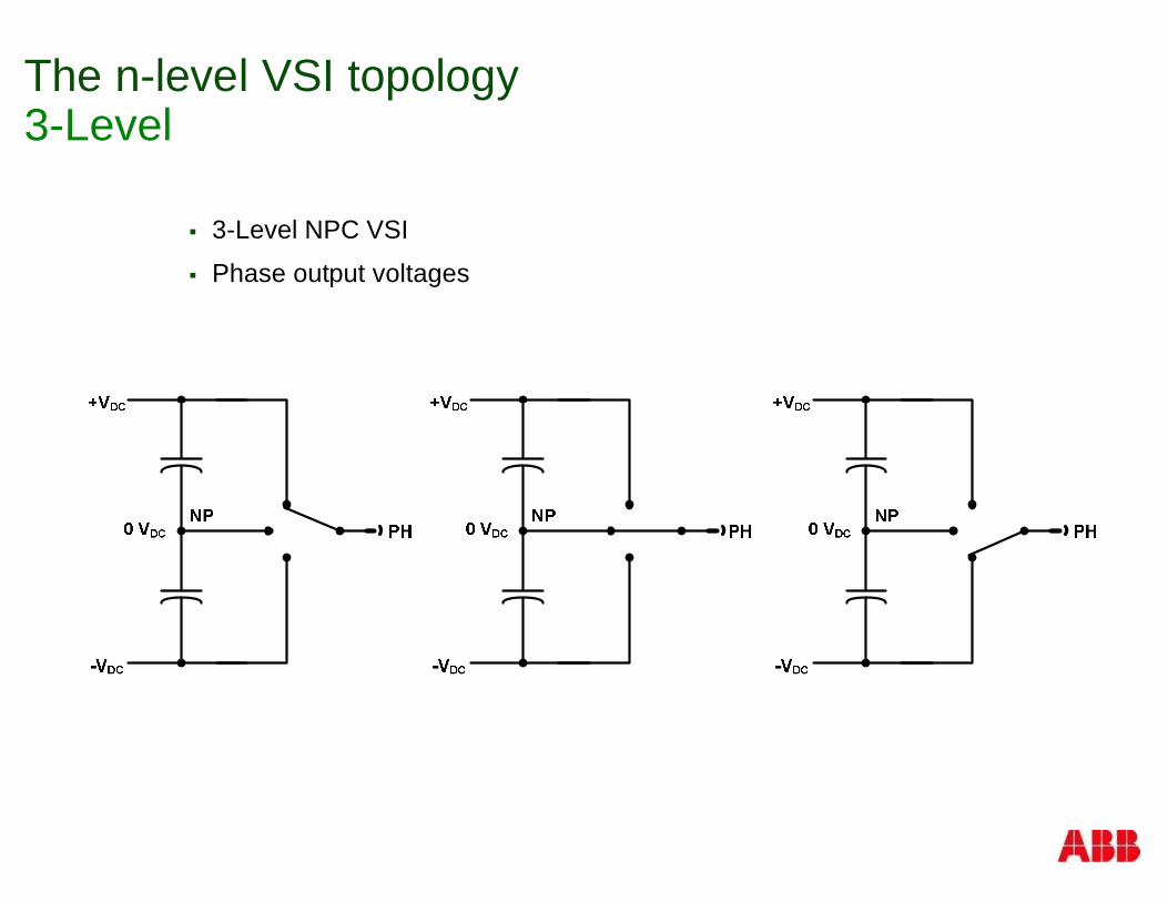
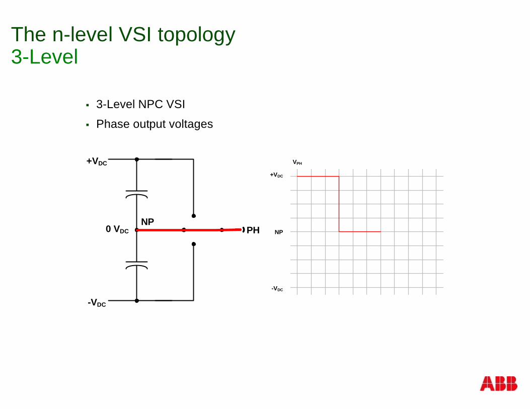
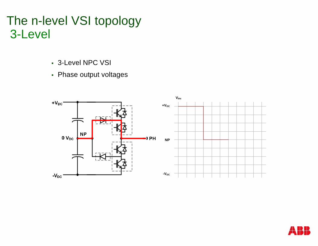
The n-level VSI topology3-Level
§ 3-Level NPC VSI
§ Phase output voltages
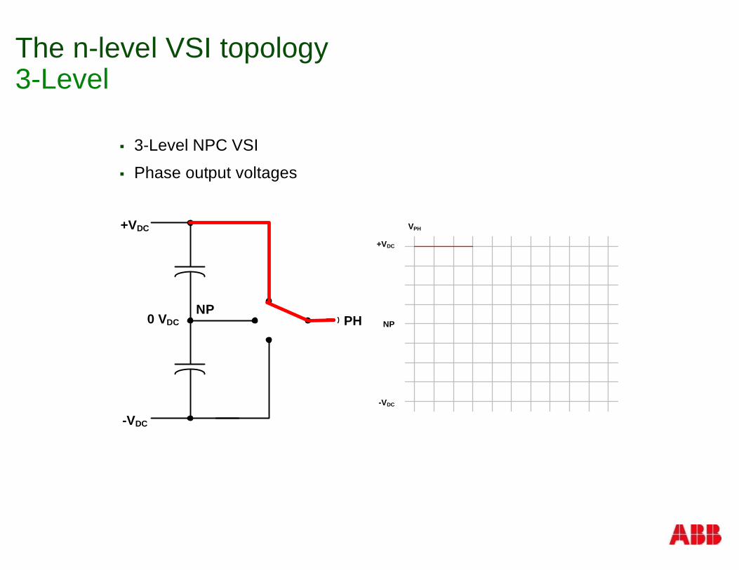
The n-level VSI topology3-Level
§ 3-Level NPC VSI
§ Phase output voltages
+VDC
NP
-VDC
VPH+VDC
-VDC
0 VDC PHNP
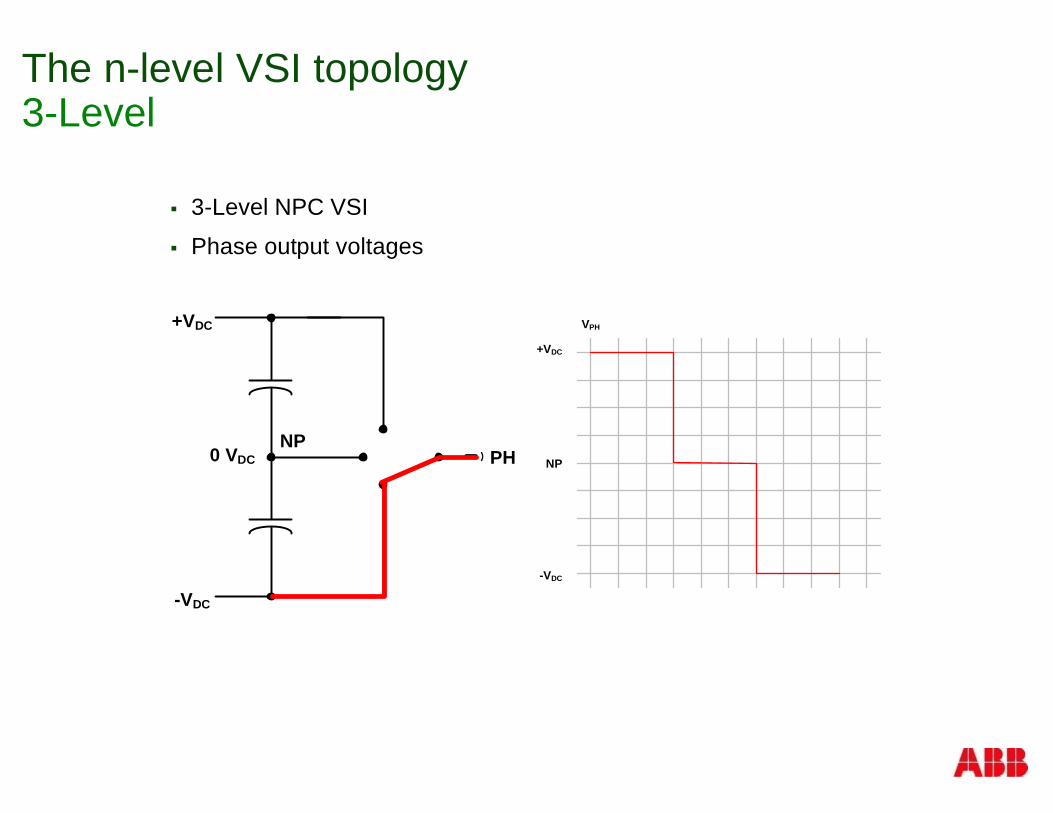
The n-level VSI topology3-Level
§ 3-Level NPC VSI
§ Phase output voltages
+VDC
NP
-VDC
VPH+VDC
-VDC
0 VDC PHNP
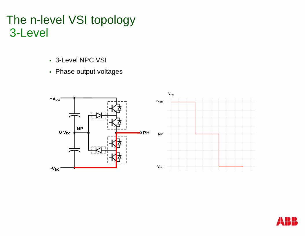
The n-level VSI topology3-Level
§ 3-Level NPC VSI
§ Phase output voltages
+VDC
-VDC
0 VDC PHNP
+VDC
NP
-VDC
VPH
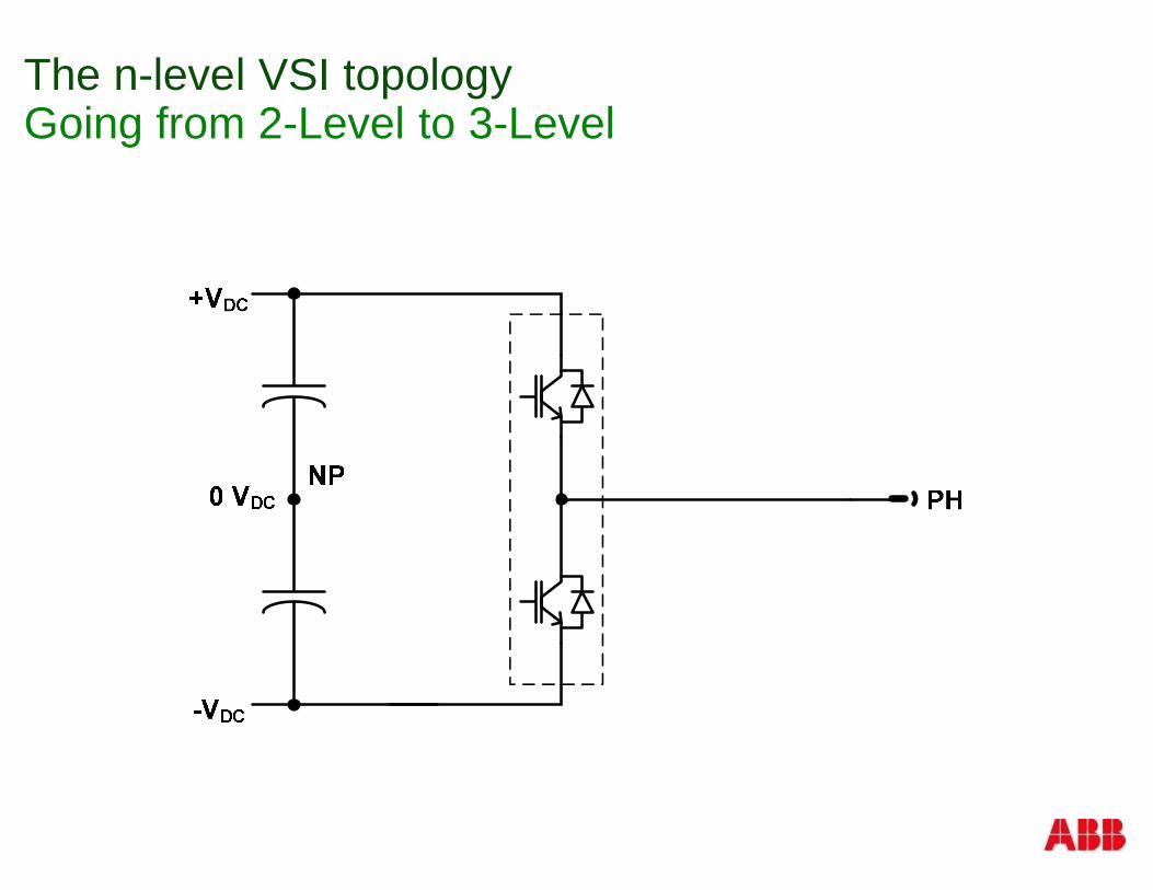
The n-level VSI topologyGoing from 2-Level to 3-Level
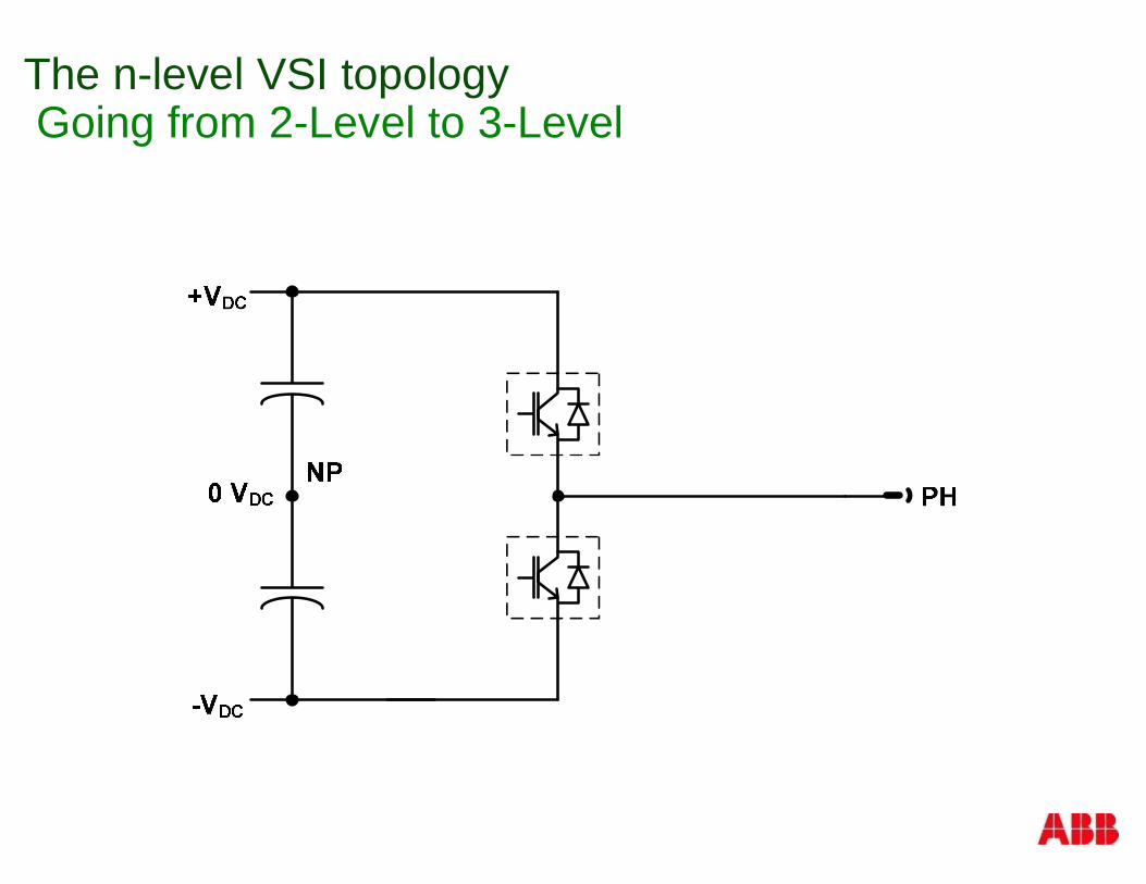
The n-level VSI topologyGoing from 2-Level to 3-Level
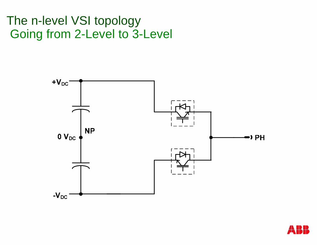
The n-level VSI topologyGoing from 2-Level to 3-Level
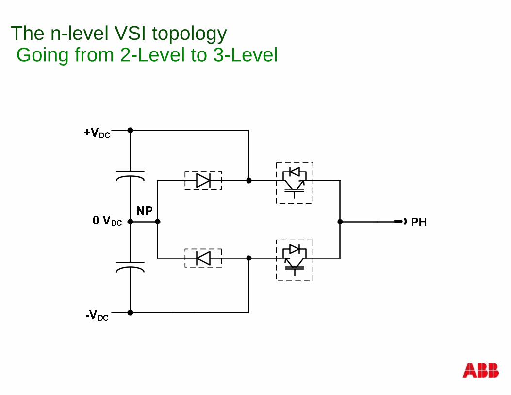
The n-level VSI topologyGoing from 2-Level to 3-Level
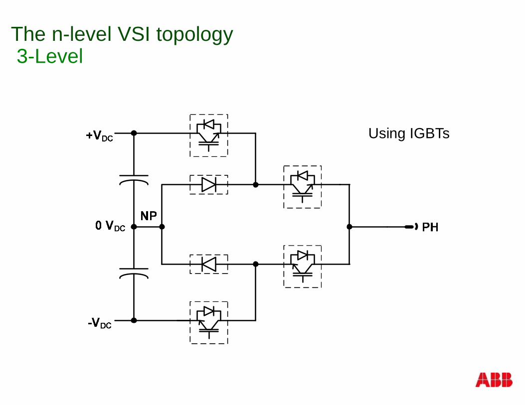
The n-level VSI topology3-Level
Using IGBTs
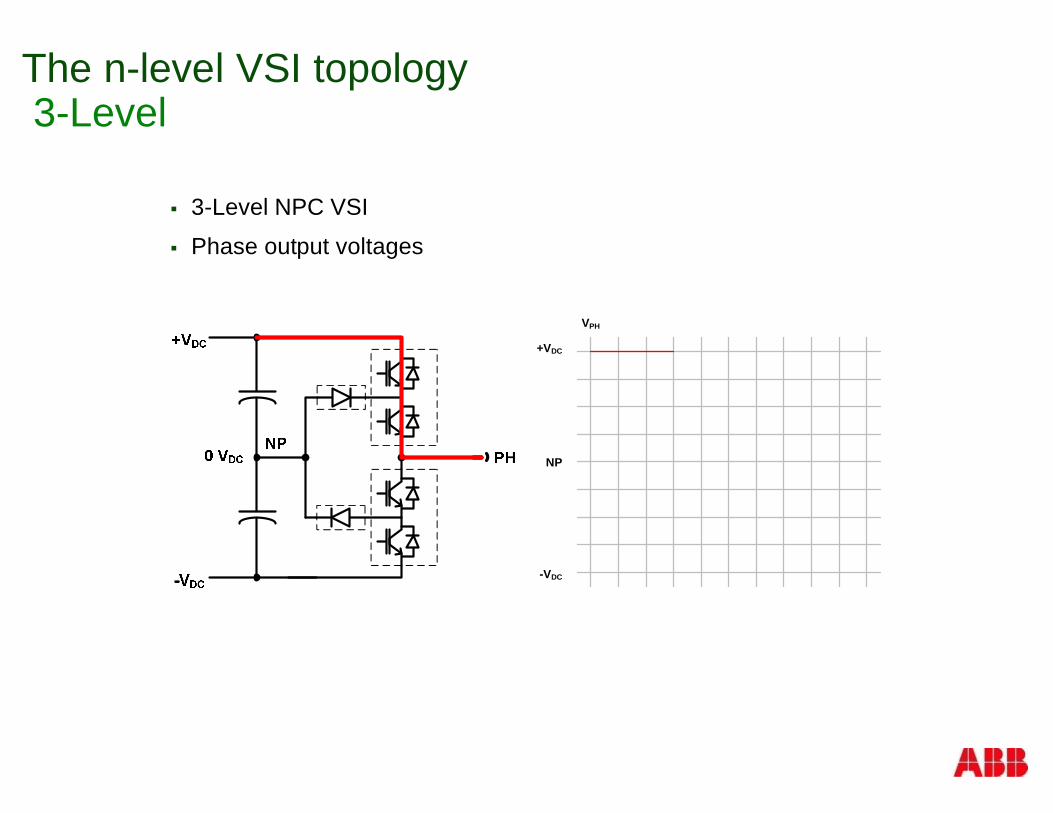
The n-level VSI topology3-Level
§ 3-Level NPC VSI
§ Phase output voltages
+VDC
NP
-VDC
VPH
The n-level VSI topology3-Level
§ 3-Level NPC VSI
§ Phase output voltages
+VDC
NP
-VDC
VPH
The n-level VSI topology3-Level
§ 3-Level NPC VSI
§ Phase output voltages
+VDC
NP
-VDC
VPH
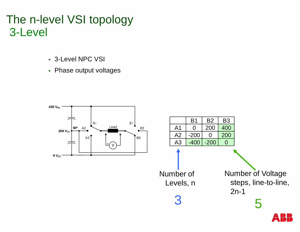
The n-level VSI topology3-Level
§ 3-Level NPC VSI
§ Phase output voltages
B1 B2 B3A1 0 200 400A2 -200 0 200A3 -400 -200 0
Number ofLevels, n
Number of Voltagesteps, line-to-line,2n-1
3 5
-8k
8k
-6k
-4k
-2k
0
2k
4k
6k
0 35m5m 10m 15m 20m 25m 30m
2DGraphSel1
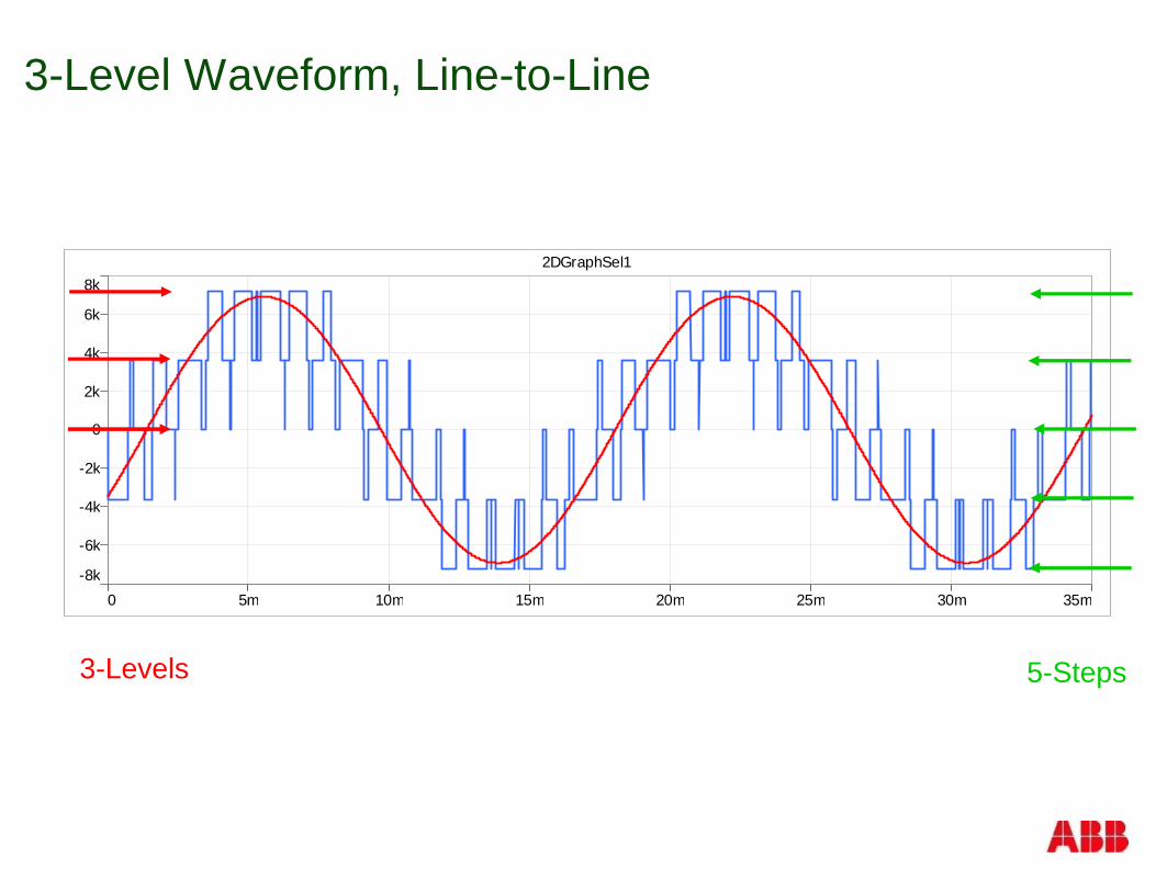
3-Level Waveform, Line-to-Line
5-Steps3-Levels
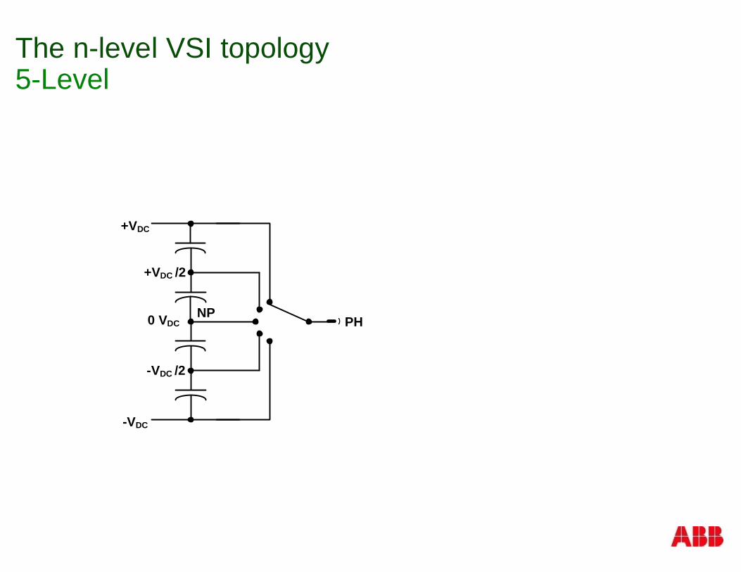
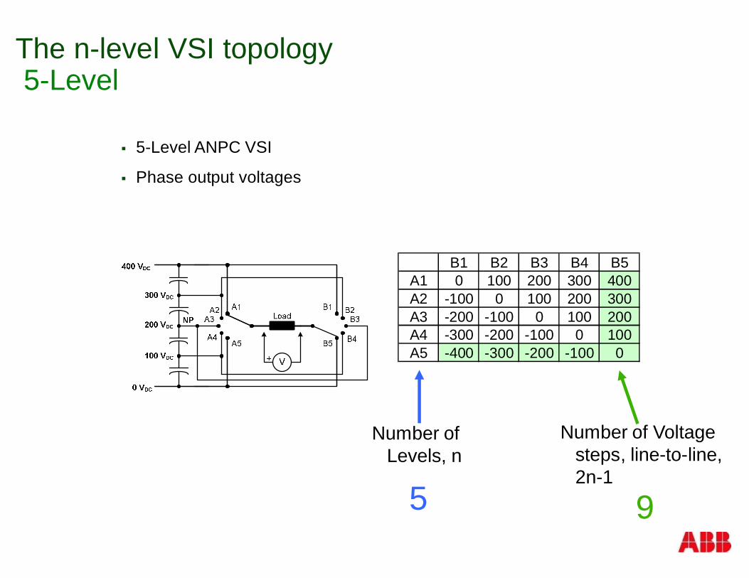
The n-level VSI topology5-Level
+VDC
-VDC
0 VDC PHNP
+VDC /2
-VDC /2
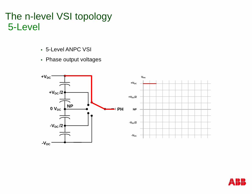
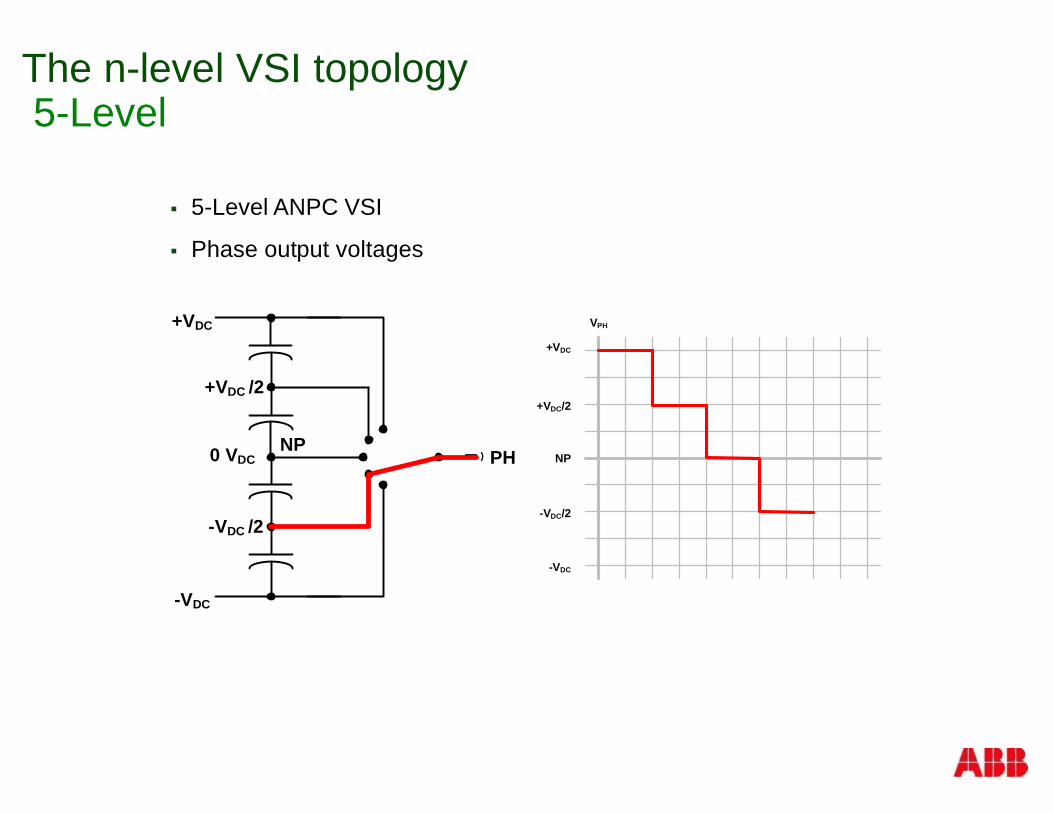
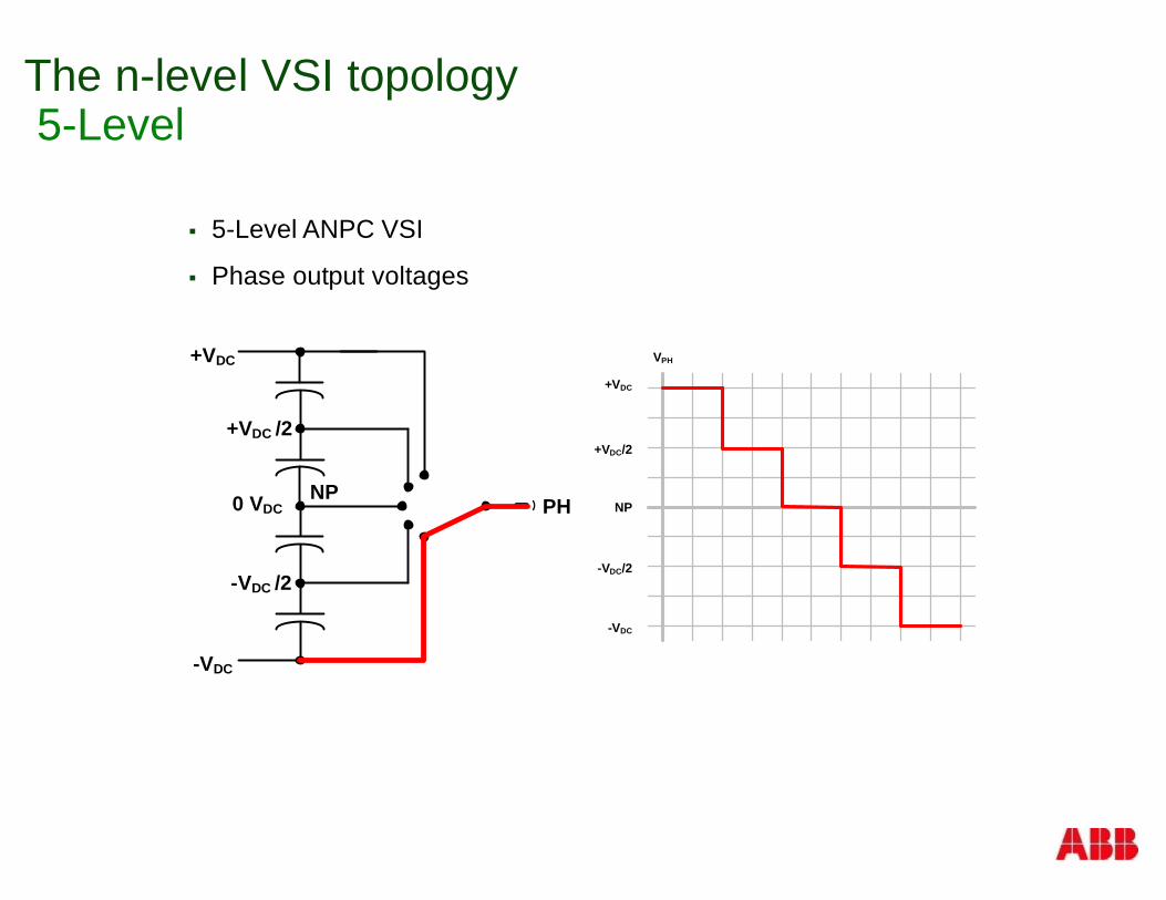
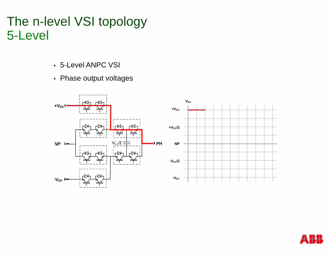
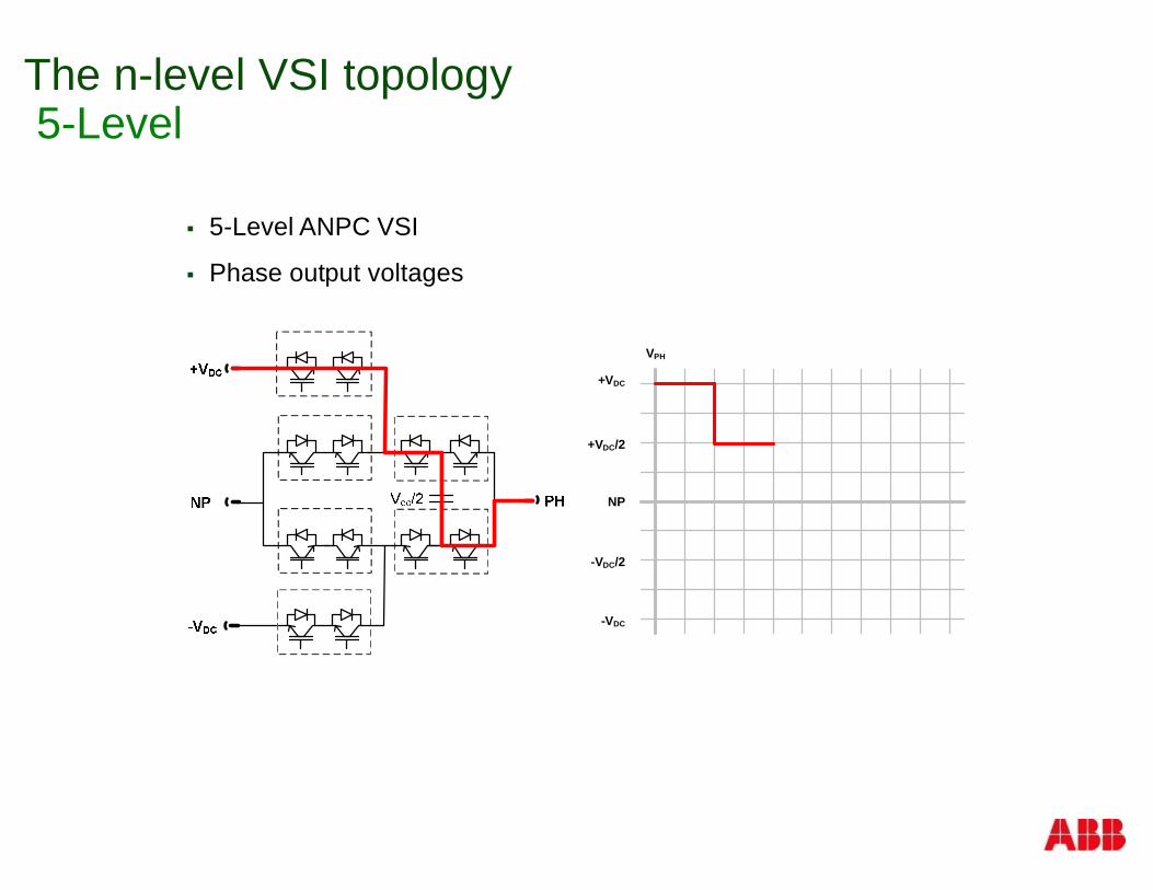
The n-level VSI topology5-Level
§ 5-Level ANPC VSI
§ Phase output voltages
+VDC
NP
-VDC
+VDC/2
-VDC/2
VPH+VDC
-VDC
0 VDC PHNP
+VDC /2
-VDC /2
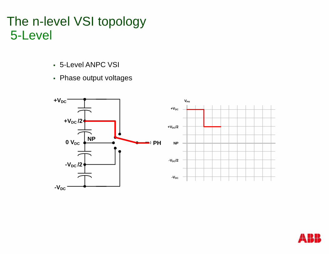
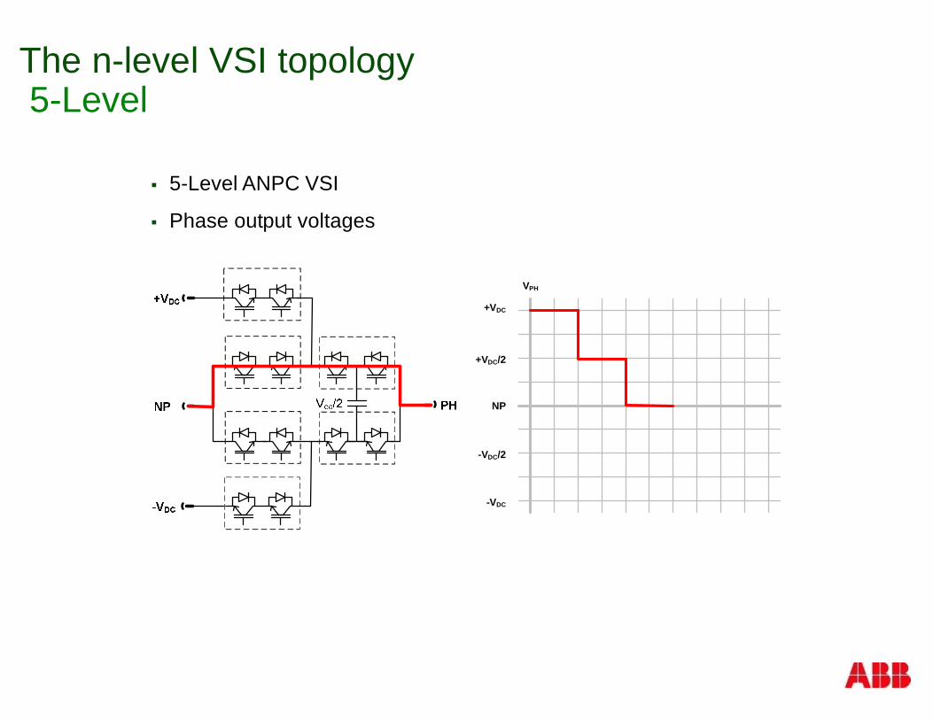
The n-level VSI topology5-Level
§ 5-Level ANPC VSI
§ Phase output voltages
+VDC
NP
-VDC
+VDC/2
-VDC/2
VPH+VDC
-VDC
0 VDC PHNP
+VDC /2
-VDC /2
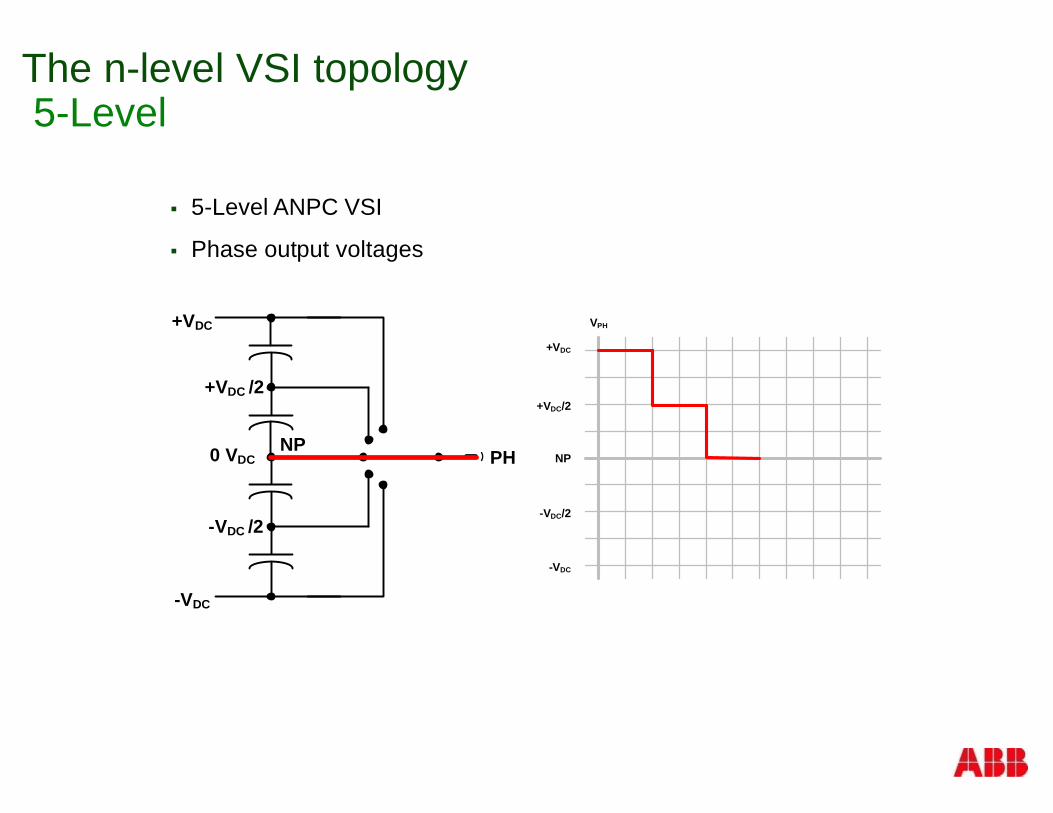
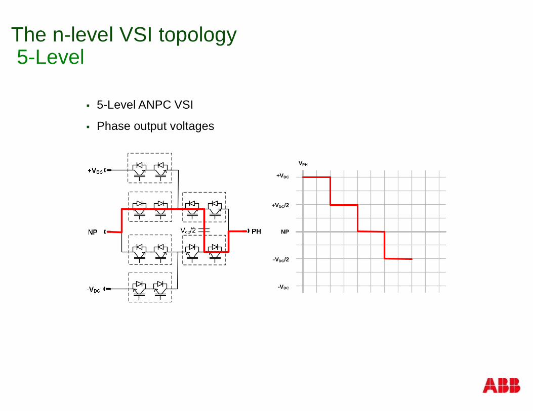
The n-level VSI topology5-Level
§ 5-Level ANPC VSI
§ Phase output voltages
+VDC
NP
-VDC
+VDC/2
-VDC/2
VPH+VDC
-VDC
0 VDC PHNP
+VDC /2
-VDC /2
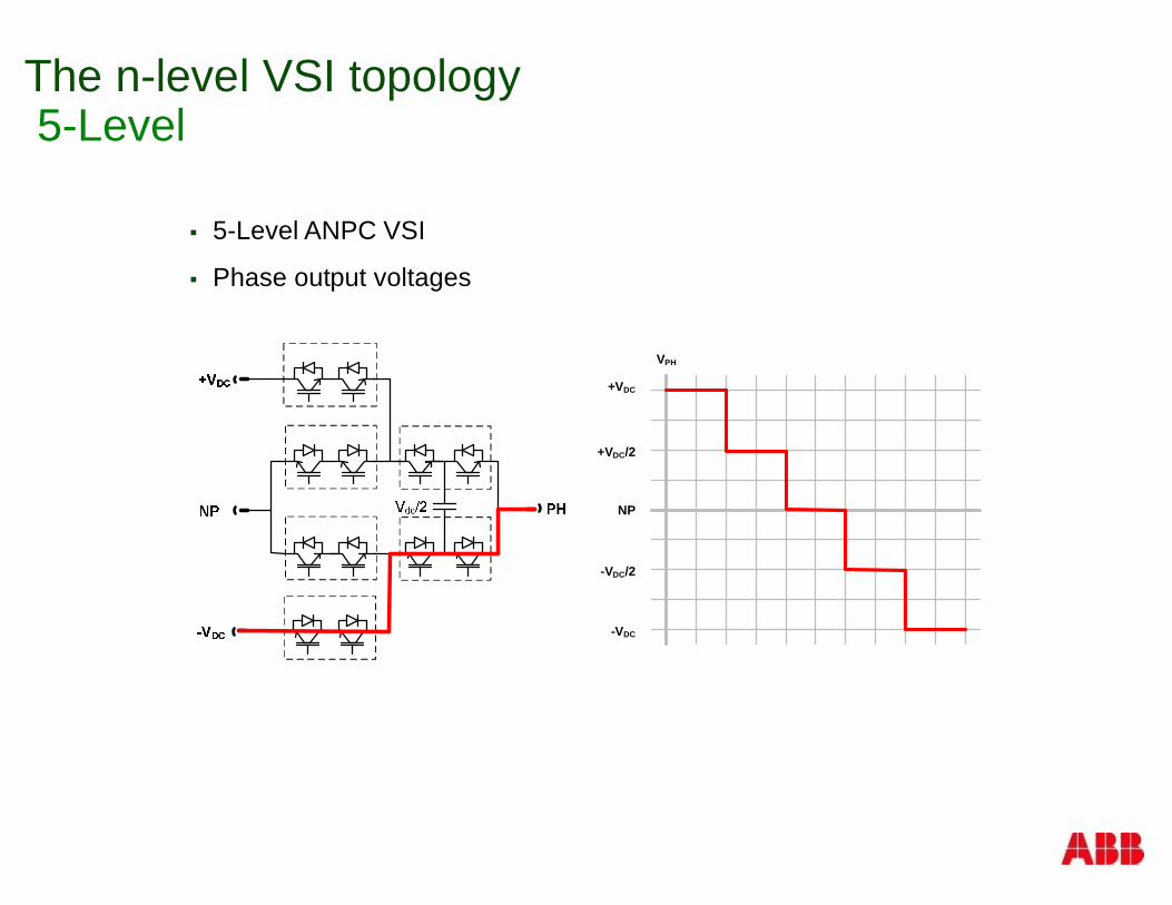
The n-level VSI topology5-Level
§ 5-Level ANPC VSI
§ Phase output voltages
+VDC
NP
-VDC
+VDC/2
-VDC/2
VPH+VDC
-VDC
0 VDC PHNP
+VDC /2
-VDC /2
The n-level VSI topology5-Level
§ 5-Level ANPC VSI
§ Phase output voltages
+VDC
NP
-VDC
+VDC/2
-VDC/2
VPH+VDC
-VDC
0 VDC PHNP
+VDC /2
-VDC /2
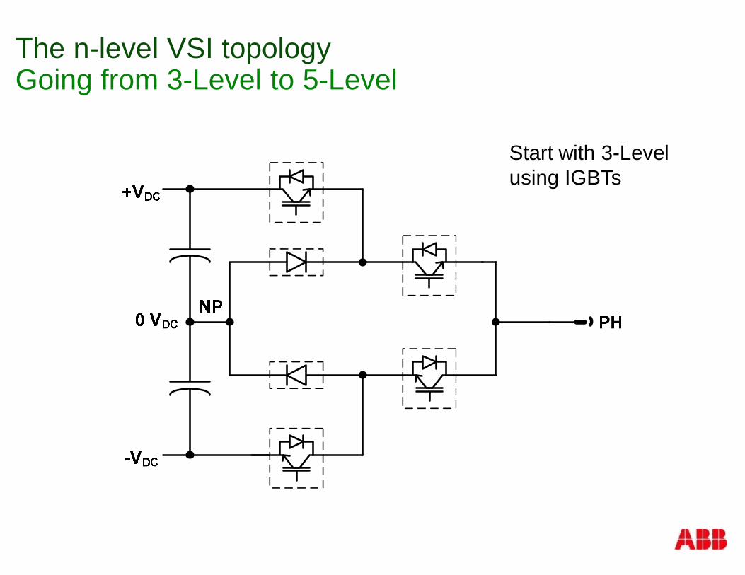
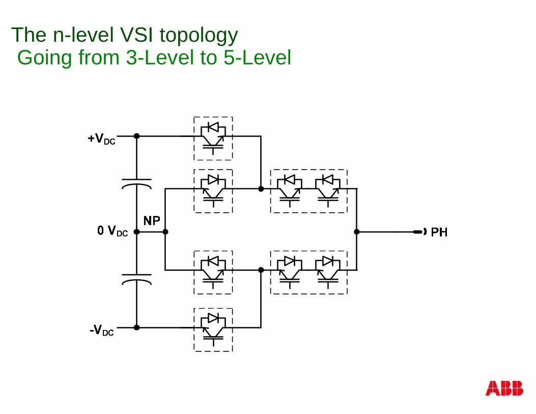
The n-level VSI topologyGoing from 3-Level to 5-Level
Start with 3-Levelusing IGBTs
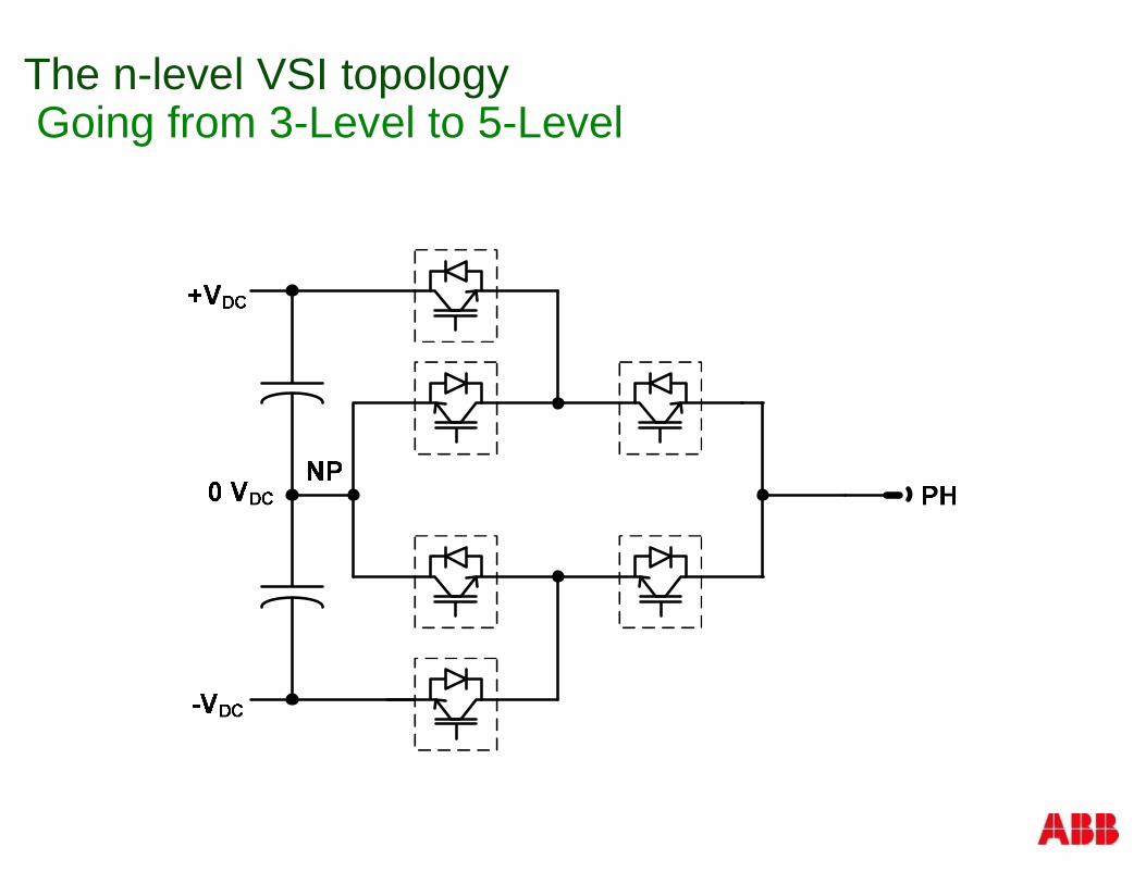
The n-level VSI topologyGoing from 3-Level to 5-Level
The n-level VSI topologyGoing from 3-Level to 5-Level
The n-level VSI topologyGoing from 3-Level to 5-Level
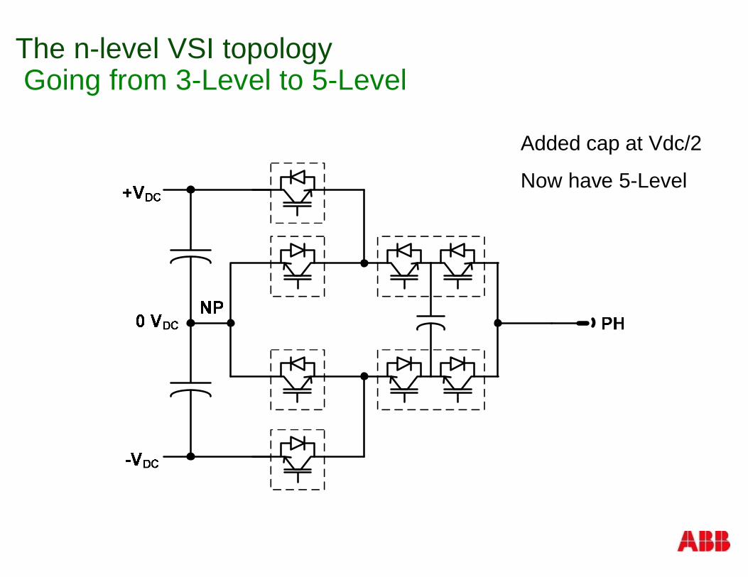
Added cap at Vdc/2
Now have 5-Level
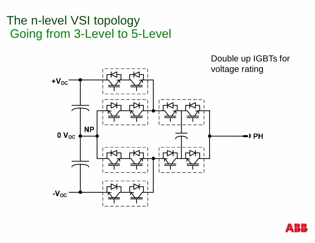
The n-level VSI topologyGoing from 3-Level to 5-Level
Double up IGBTs forvoltage rating
The n-level VSI topology5-Level
§ 5-Level ANPC VSI
§ Phase output voltages
+VDC
NP
-VDC
+VDC/2
-VDC/2
VPH
The n-level VSI topology5-Level
§ 5-Level ANPC VSI
§ Phase output voltages
+VDC
NP
-VDC
+VDC/2
-VDC/2
VPH
The n-level VSI topology5-Level
§ 5-Level ANPC VSI
§ Phase output voltages
+VDC
NP
-VDC
+VDC/2
-VDC/2
VPH
The n-level VSI topology5-Level
§ 5-Level ANPC VSI
§ Phase output voltages
+VDC
NP
-VDC
+VDC/2
-VDC/2
VPH
The n-level VSI topology5-Level
§ 5-Level ANPC VSI
§ Phase output voltages
+VDC
NP
-VDC
+VDC/2
-VDC/2
VPH
The n-level VSI topology5-Level
§ 5-Level ANPC VSI
§ Phase output voltages
B1 B2 B3 B4 B5A1 0 100 200 300 400A2 -100 0 100 200 300A3 -200 -100 0 100 200A4 -300 -200 -100 0 100A5 -400 -300 -200 -100 0
Number ofLevels, n
Number of Voltagesteps, line-to-line,2n-1
5 9
-8.0k
8.0k
-6.0k
-4.0k
-2.0k
0
2.0k
4.0k
6.0k
0 35m5m 10m 15m 20m 25m 30m
2DGraphSel1
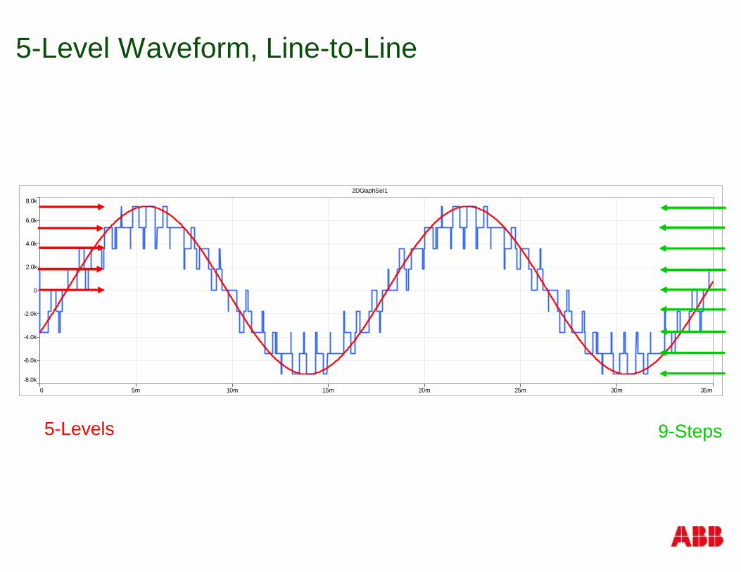
5-Level Waveform, Line-to-Line
9-Steps5-Levels
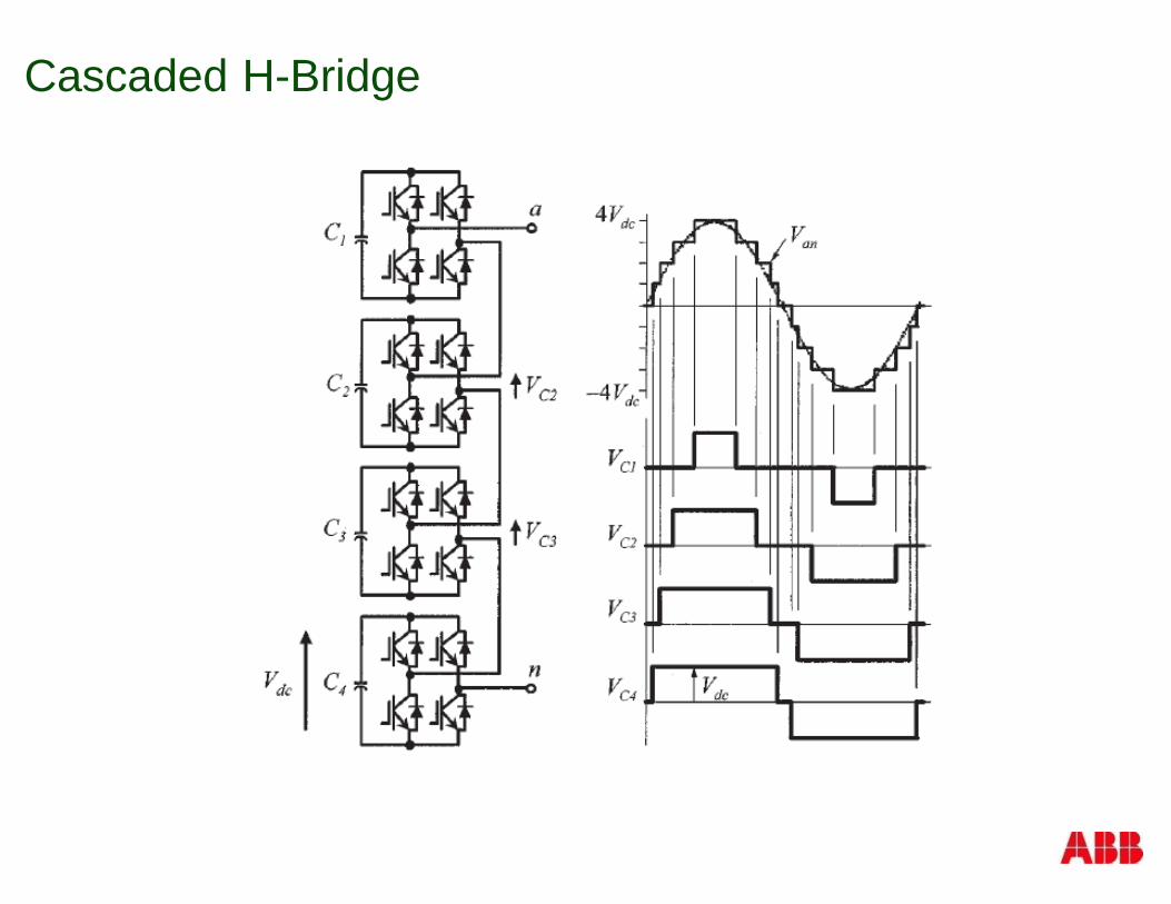
Cascaded H-Bridge
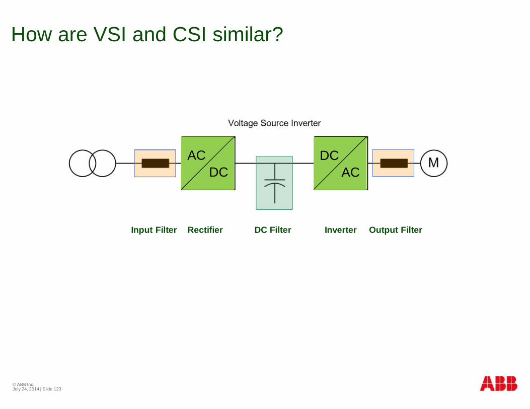
How are VSI and CSI similar?
© ABB Inc.July 24, 2014 | Slide 123
Input Filter Rectifier DC Filter Inverter Output Filter
ACDC
DCAC
ACDC
DCAC
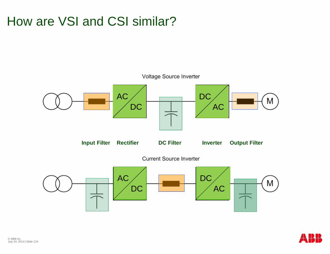
How are VSI and CSI similar?
© ABB Inc.July 24, 2014 | Slide 124
Input Filter Rectifier DC Filter Inverter Output Filter
ACDC
DCAC
ACDC
DCAC
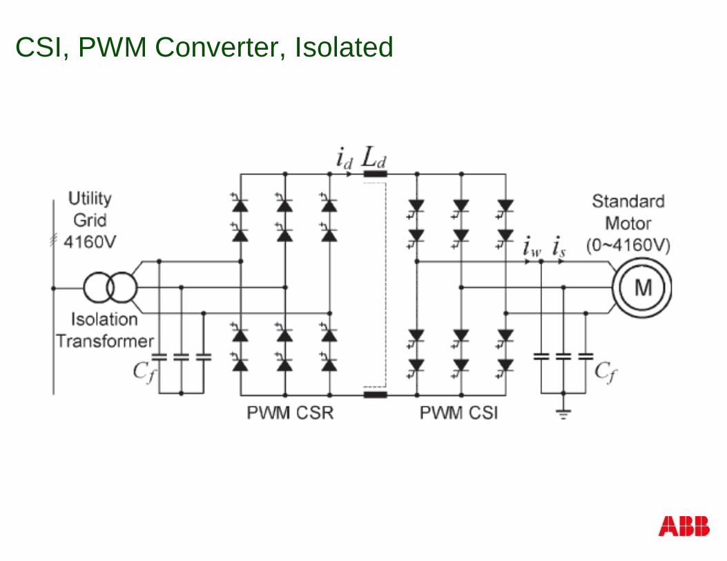
CSI, PWM Converter, Isolated
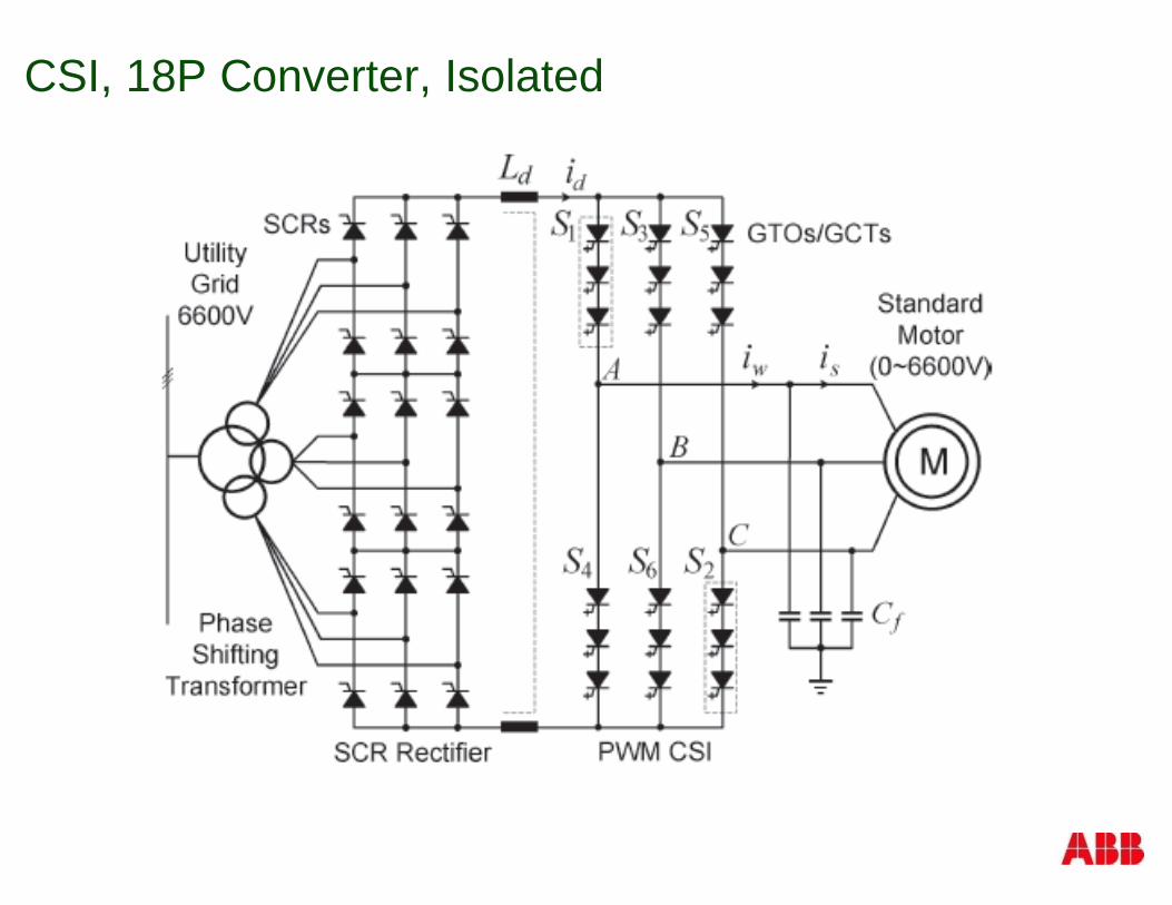
CSI, 18P Converter, Isolated
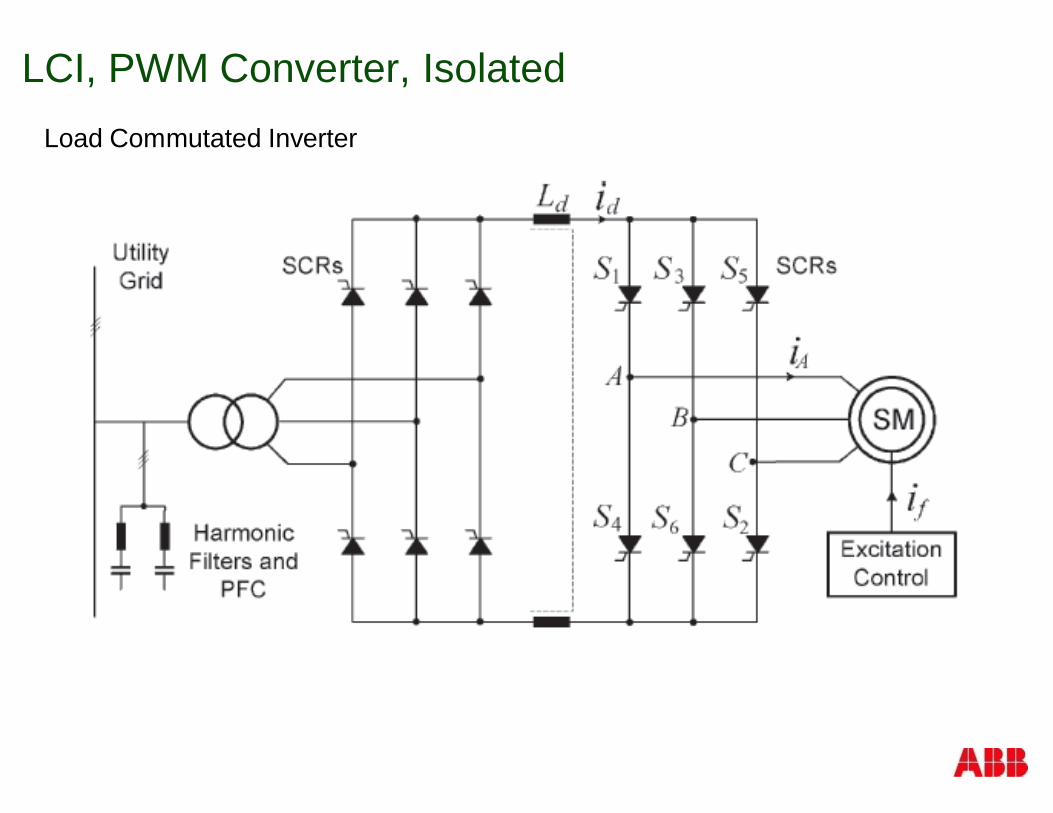
LCI, PWM Converter, IsolatedLoad Commutated Inverter
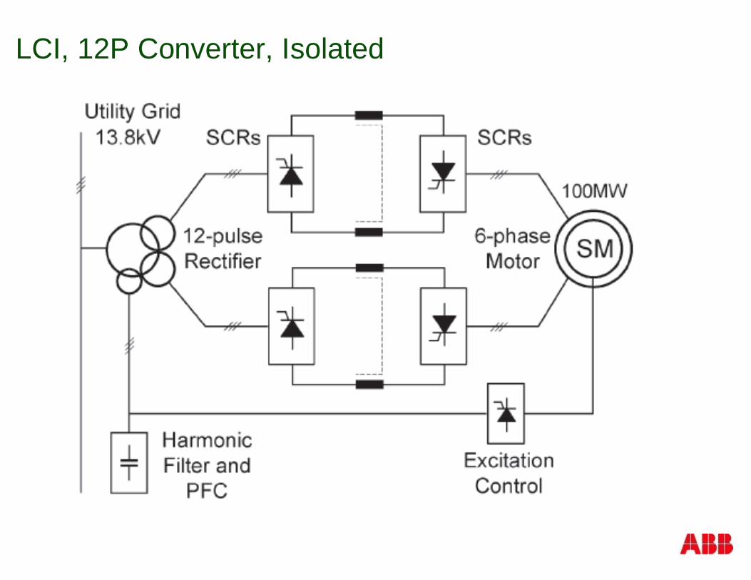
LCI, 12P Converter, Isolated
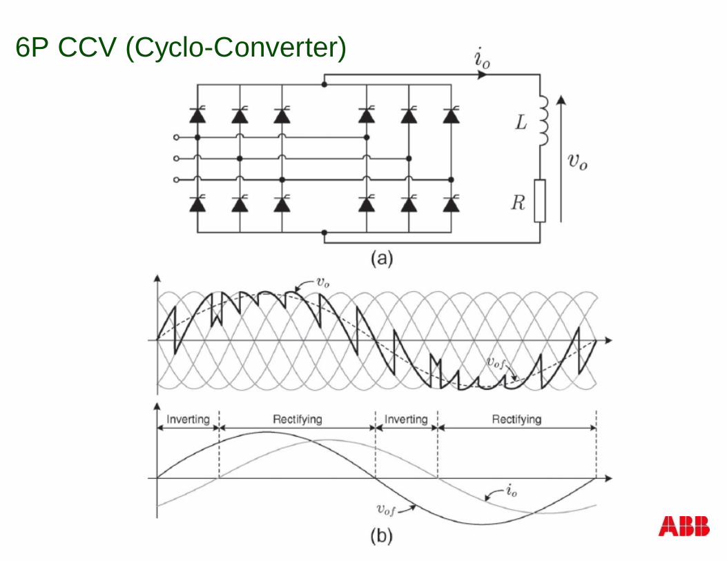
6P CCV (Cyclo-Converter)
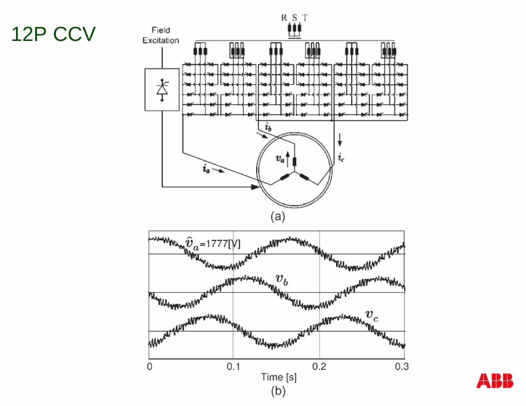
12P CCV
Reflected Waves
§ Affected by:
§ Length of cable between drive and motor
§ Rate of rise of voltage (dV/dt)
§ Voltage step size
§ Pulse width
© ABB Inc.July 24, 2014 | Slide 131
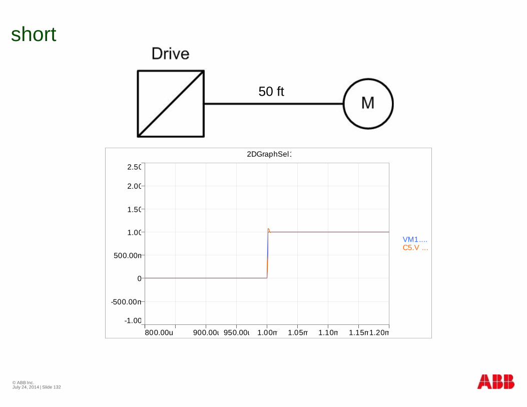
short
© ABB Inc.July 24, 2014 | Slide 132
-1.00
2.50
-500.00m
0
500.00m
1.00
1.50
2.00
800.00u 1.20m900.00u 950.00u 1.00m 1.05m 1.10m 1.15m
2DGraphSel1
VM1.... C5.V ...
50 ft
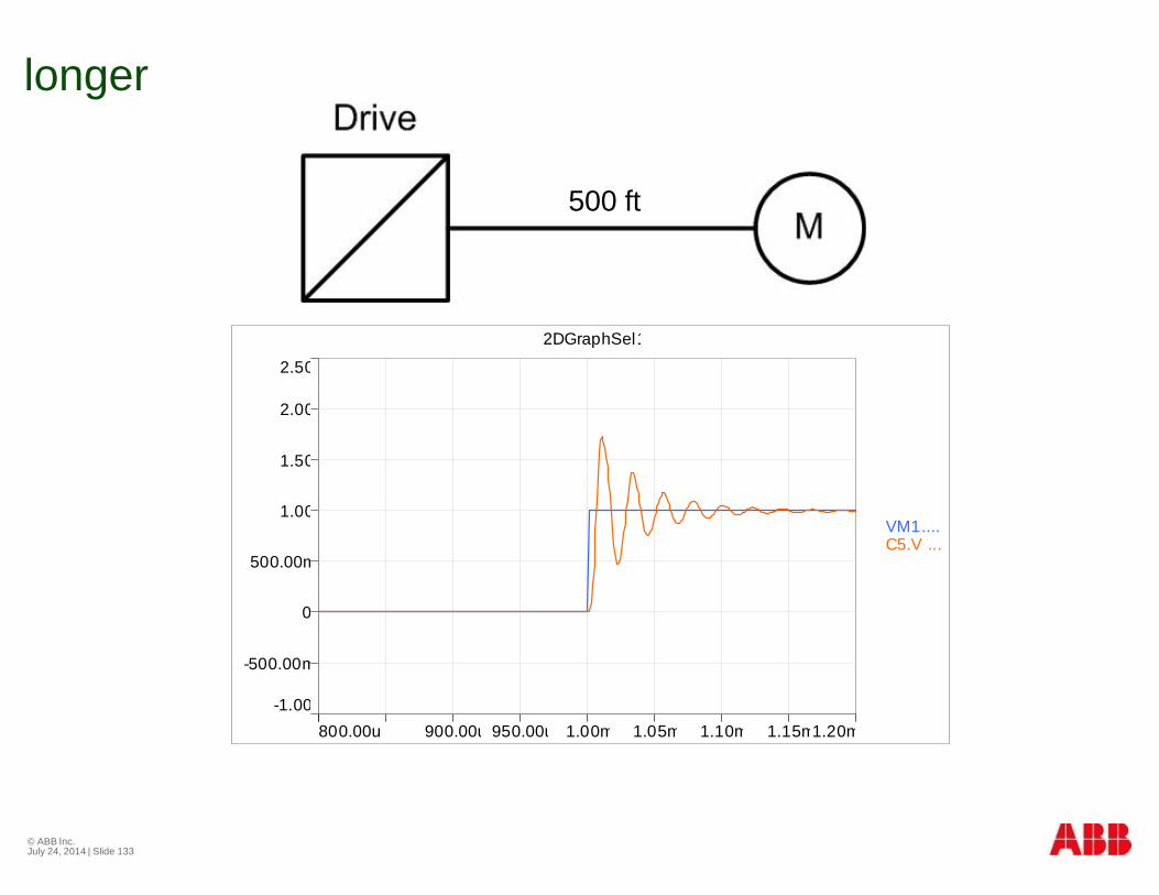
longer
© ABB Inc.July 24, 2014 | Slide 133
-1.00
2.50
-500.00m
0
500.00m
1.00
1.50
2.00
800.00u 1.20m900.00u 950.00u 1.00m 1.05m 1.10m 1.15m
2DGraphSel1
VM1.... C5.V ...
500 ft
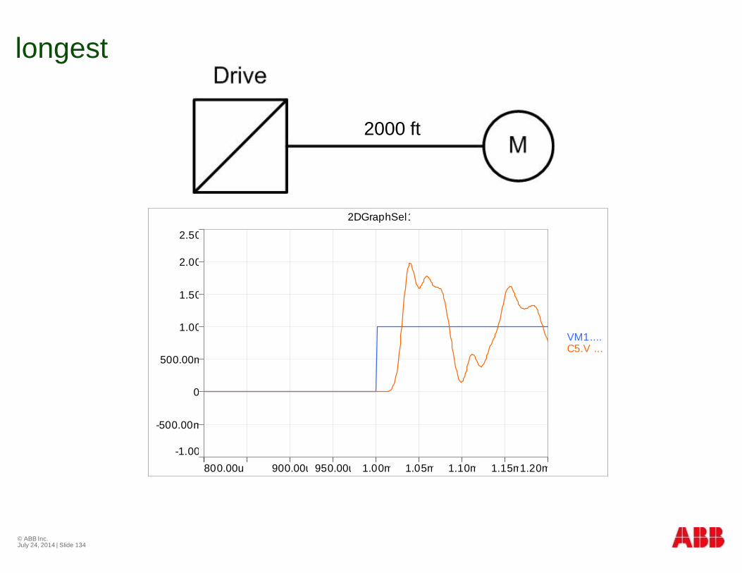
longest
© ABB Inc.July 24, 2014 | Slide 134
-1.00
2.50
-500.00m
0
500.00m
1.00
1.50
2.00
800.00u 1.20m900.00u 950.00u 1.00m 1.05m 1.10m 1.15m
2DGraphSel1
VM1.... C5.V ...
2000 ft
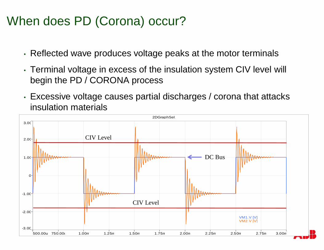
When does PD (Corona) occur?
• Reflected wave produces voltage peaks at the motor terminals
• Terminal voltage in excess of the insulation system CIV level willbegin the PD / CORONA process
• Excessive voltage causes partial discharges / corona that attacksinsulation materials
-3.00
3.00
-2.00
-1.00
0
1.00
2.00
500.00u 3.00m750.00u 1.00m 1.25m 1.50m 1.75m 2.00m 2.25m 2.50m 2.75m
2DGraphSel1
VM1.V [V] VM2.V [V]
DC Bus
CIV Level
CIV Level
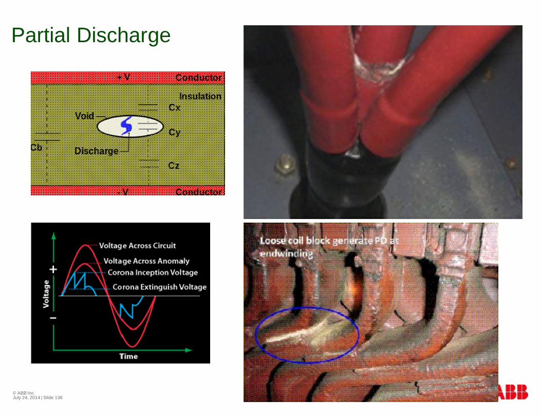
Partial Discharge
© ABB Inc.July 24, 2014 | Slide 136
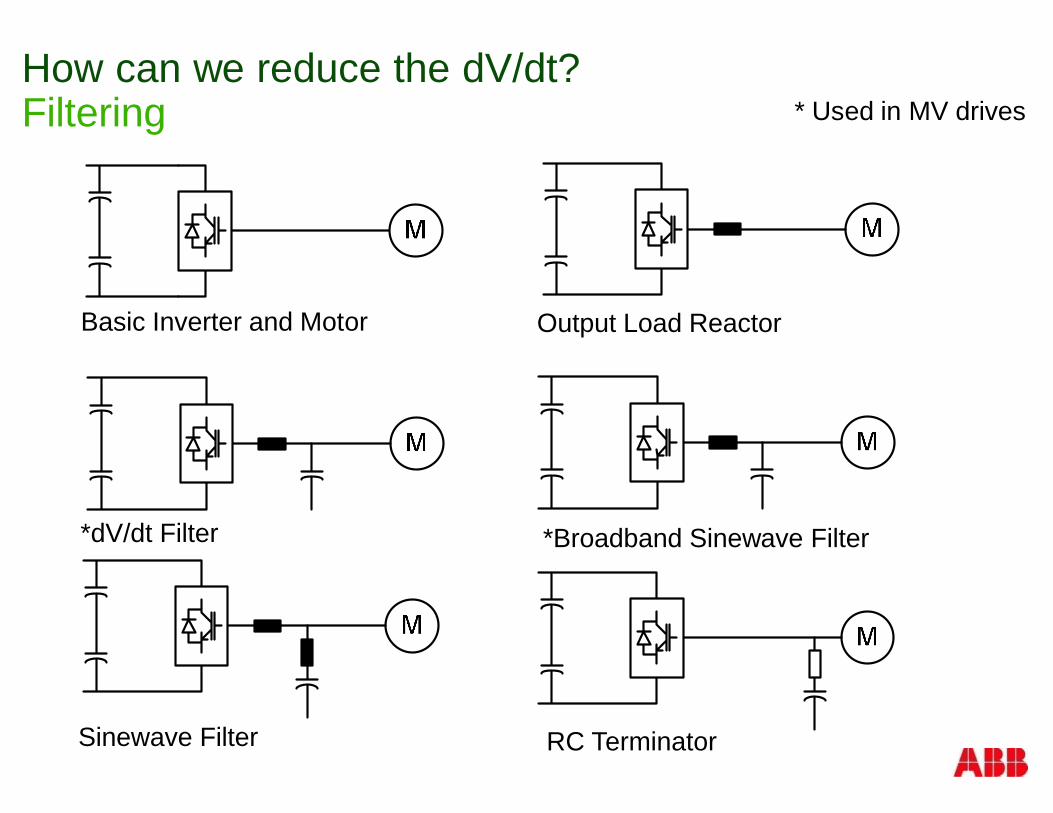
How can we reduce the dV/dt?Filtering
Basic Inverter and Motor
*dV/dt Filter
Sinewave Filter
Output Load Reactor
*Broadband Sinewave Filter
RC Terminator
* Used in MV drives
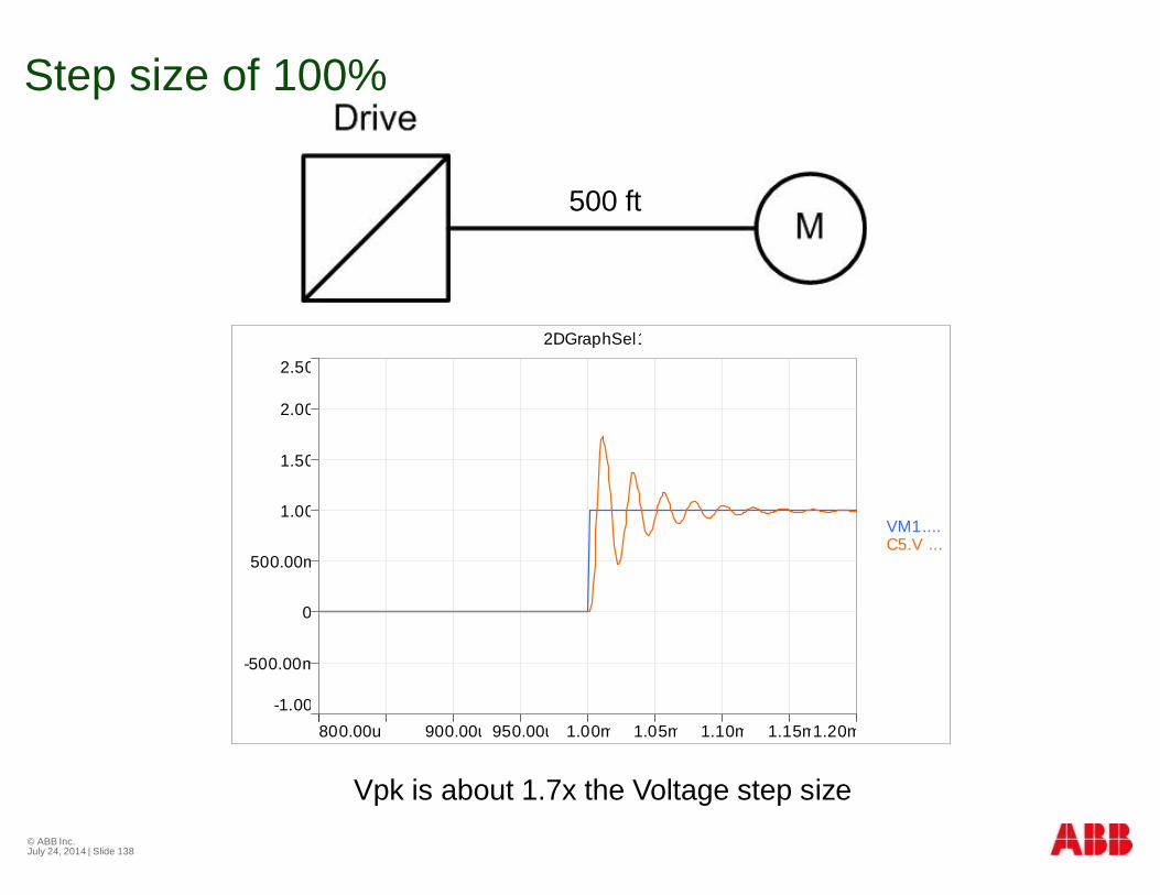
Step size of 100%
© ABB Inc.July 24, 2014 | Slide 138
-1.00
2.50
-500.00m
0
500.00m
1.00
1.50
2.00
800.00u 1.20m900.00u 950.00u 1.00m 1.05m 1.10m 1.15m
2DGraphSel1
VM1.... C5.V ...
500 ft
Vpk is about 1.7x the Voltage step size
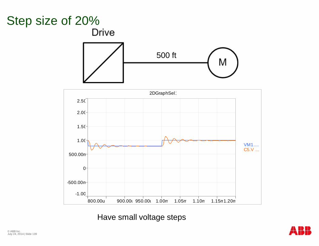
Step size of 20%
© ABB Inc.July 24, 2014 | Slide 139
-1.00
2.50
-500.00m
0
500.00m
1.00
1.50
2.00
800.00u 1.20m900.00u 950.00u 1.00m 1.05m 1.10m 1.15m
2DGraphSel1
VM1.... C5.V ...
500 ft
Have small voltage steps
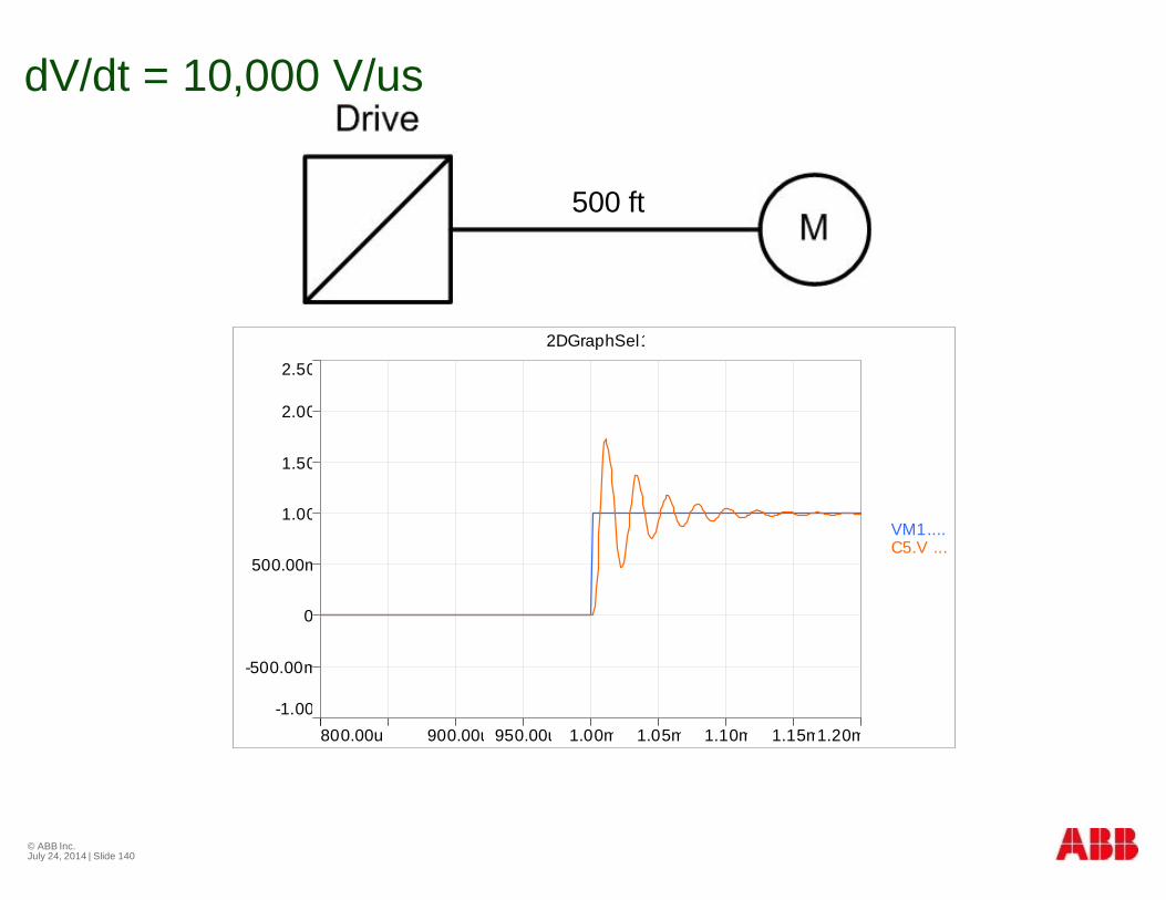
dV/dt = 10,000 V/us
© ABB Inc.July 24, 2014 | Slide 140
500 ft
-1.00
2.50
-500.00m
0
500.00m
1.00
1.50
2.00
800.00u 1.20m900.00u 950.00u 1.00m 1.05m 1.10m 1.15m
2DGraphSel1
VM1.... C5.V ...
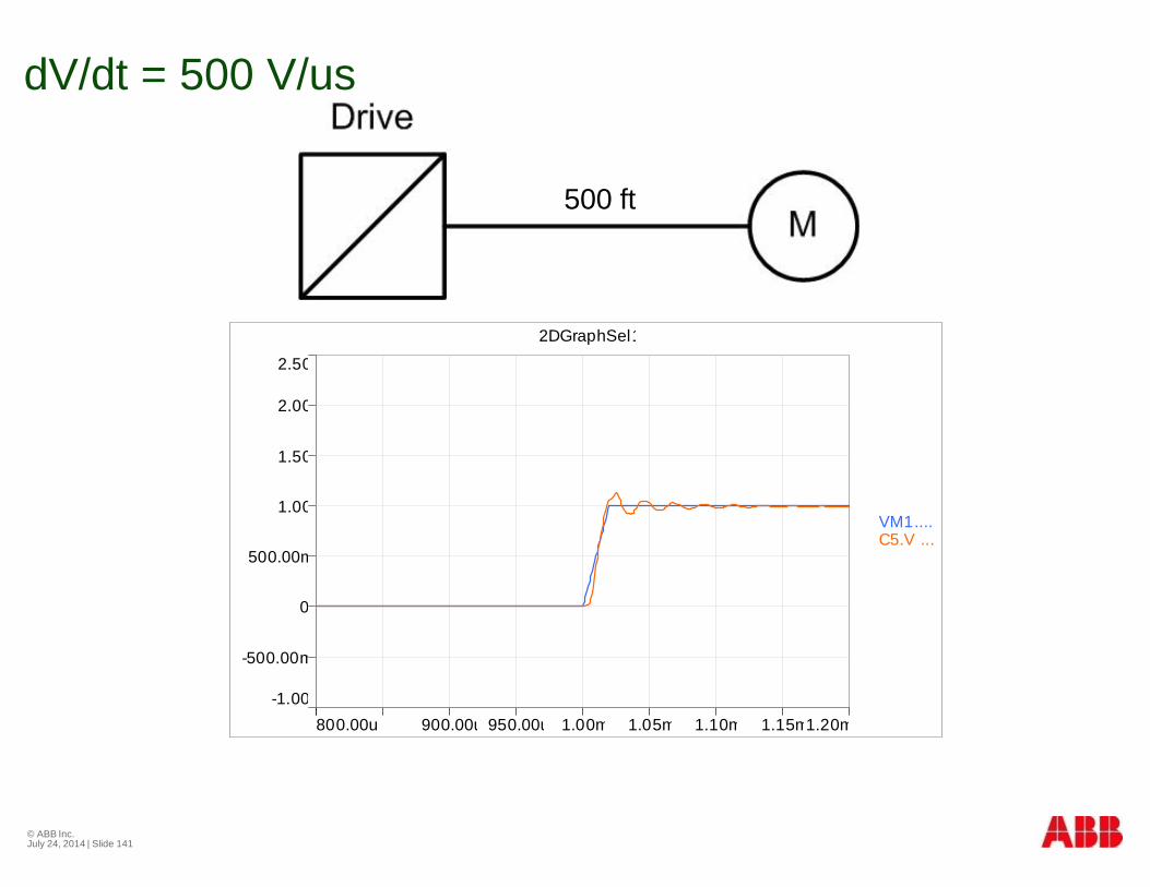
dV/dt = 500 V/us
© ABB Inc.July 24, 2014 | Slide 141
500 ft
-1.00
2.50
-500.00m
0
500.00m
1.00
1.50
2.00
800.00u 1.20m900.00u 950.00u 1.00m 1.05m 1.10m 1.15m
2DGraphSel1
VM1.... C5.V ...
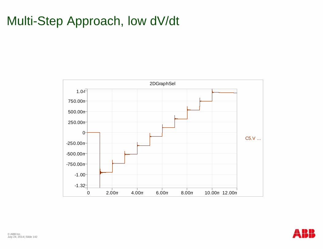
Multi-Step Approach, low dV/dt
© ABB Inc.July 24, 2014 | Slide 142
-1.32
1.04
-1.00
-750.00m
-500.00m
-250.00m
0
250.00m
500.00m
750.00m
0 12.00m2.00m 4.00m 6.00m 8.00m 10.00m
2DGraphSel1
C5.V ...
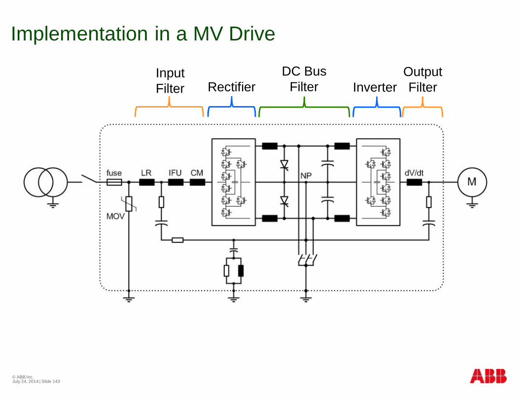
Implementation in a MV Drive
© ABB Inc.July 24, 2014 | Slide 143
InputFilter
OutputFilter
DC BusFilterRectifier Inverter
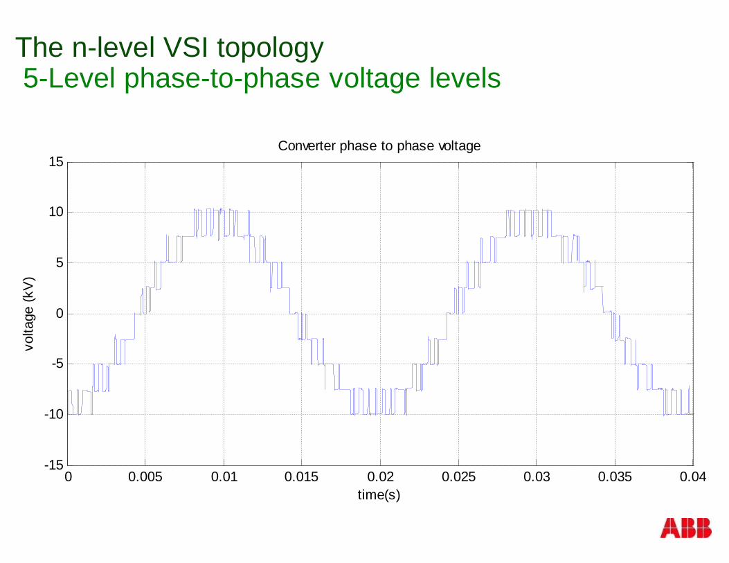
The n-level VSI topology5-Level phase-to-phase voltage levels
0 0.005 0.01 0.015 0.02 0.025 0.03 0.035 0.04-15
-10
-5
0
5
10
15
volta
ge(k
V)
Converter phase to phase voltage
time(s)
Protection
§ PQ Events
§ Over-Voltage
§ Over-Current
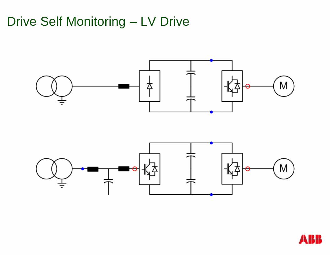
Drive Self Monitoring – LV Drive
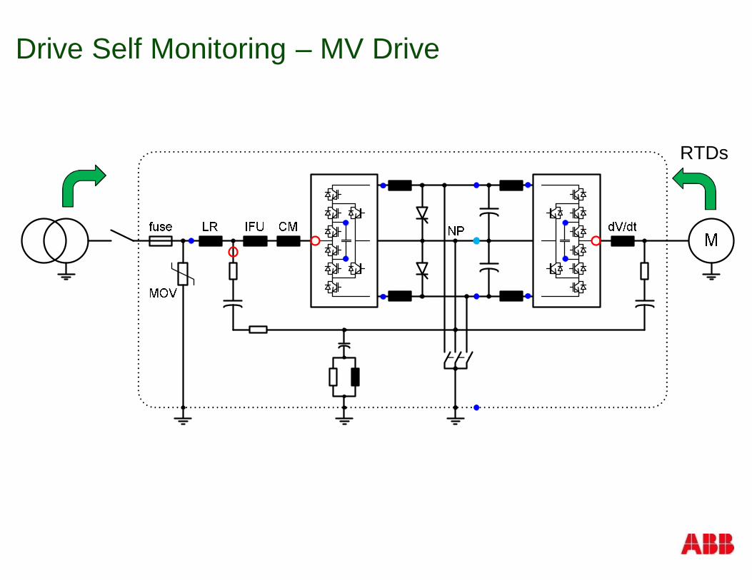
Drive Self Monitoring – MV Drive
RTDs
© ABB GroupJuly 24, 2014 | Slide 148
Operation and Protection Concept
§ Try to keep operating
§ If unable to due to external issues§ Alarm, but don’t stop
§ Trip
§ If catastrophic failure§ Limit collateral damage
§ Minimal MTTR (mean time to repair)
§ Look-out for its motor and transformer, too!§ Like a big brother or sister
© ABB LV DrivesProperty of ABB LV Drives, Do Not CopySlide 149
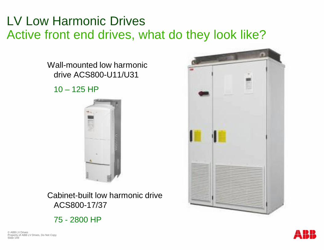
LV Low Harmonic DrivesActive front end drives, what do they look like?
Wall-mounted low harmonicdrive ACS800-U11/U31
10 – 125 HP
Cabinet-built low harmonic driveACS800-17/37
75 - 2800 HP
© ABB LV DrivesProperty of ABB LV Drives, Do Not CopySlide 150
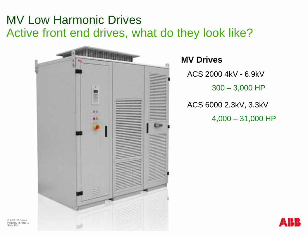
MV Low Harmonic DrivesActive front end drives, what do they look like?
MV DrivesACS 2000 4kV - 6.9kV
300 – 3,000 HP
ACS 6000 2.3kV, 3.3kV
4,000 – 31,000 HP
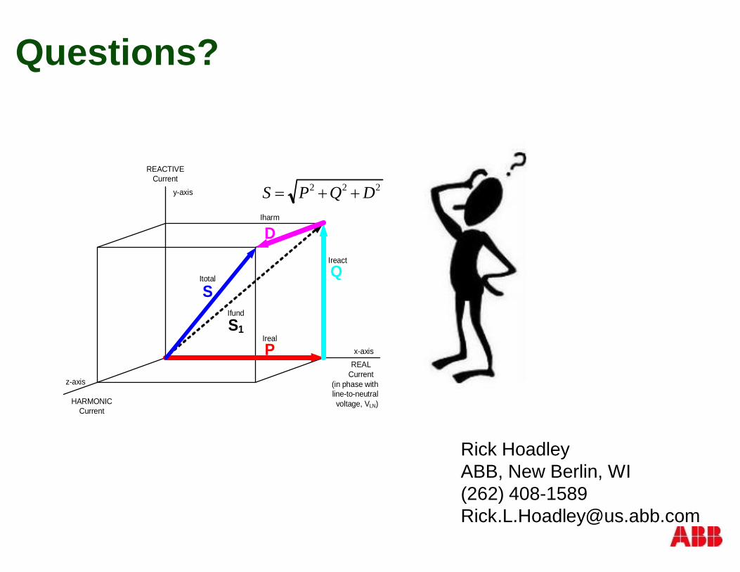
Questions?
Rick HoadleyABB, New Berlin, WI(262) [email protected]
HARMONICCurrent
Ireact
Ireal
Ifund
Itotal
Iharm
(in phase withline-to-neutral voltage, VLN)
REACTIVECurrent
Q
PS1
S
D
x-axis
y-axis
z-axis
REALCurrent
222 DQPS ++=

© ABB GroupJuly 24, 2014 | Slide 152