Embed Size (px)
Citation preview
www.tridonic.com 1Subject to change without notice.
Data sheet 08/18-CO074-25
luxCONTROL lighting control system
basicDIM
Product description
• Compact dimensions for luminaire installation
• For up to 20 DSI or DALI devices (max. 10 per output channel)
• DALI IN input
• 2 DALI/DSI output channels with adjustable offset from
channel 2 to channel 1
• 1 relais output
• Sensor input for up to 4 basicDIM DGC sensors 5DPI 14
• 2 switch inputs for on/off switching and dimming
• Individual adjustment of the parameters with
basicDIM DGC Programmer or
software masterCONFIGURATOR
• 5-year guarantee
ÈWiring diagrams and installation examples, page 10
basicDIM DGC
Compact control module
www.tridonic.com 2Subject to change without notice.
Data sheet 08/18-CO074-25
luxCONTROL lighting control system
basicDIM
basicDIM DGC Sensor 5DPI 14f
ACC
ES-
SOR
IES
44,4
Ø13,9
16,4
1,93
12,8
2
Ordering dataType Article number Packaging, carton
basicDIM DGC Sensor 5DPI 14f Luminaire installation 28000933 40 pc(s).
basicDIM DGC Sensor 5DPI 14f black Luminaire installation 28001696 40 pc(s).
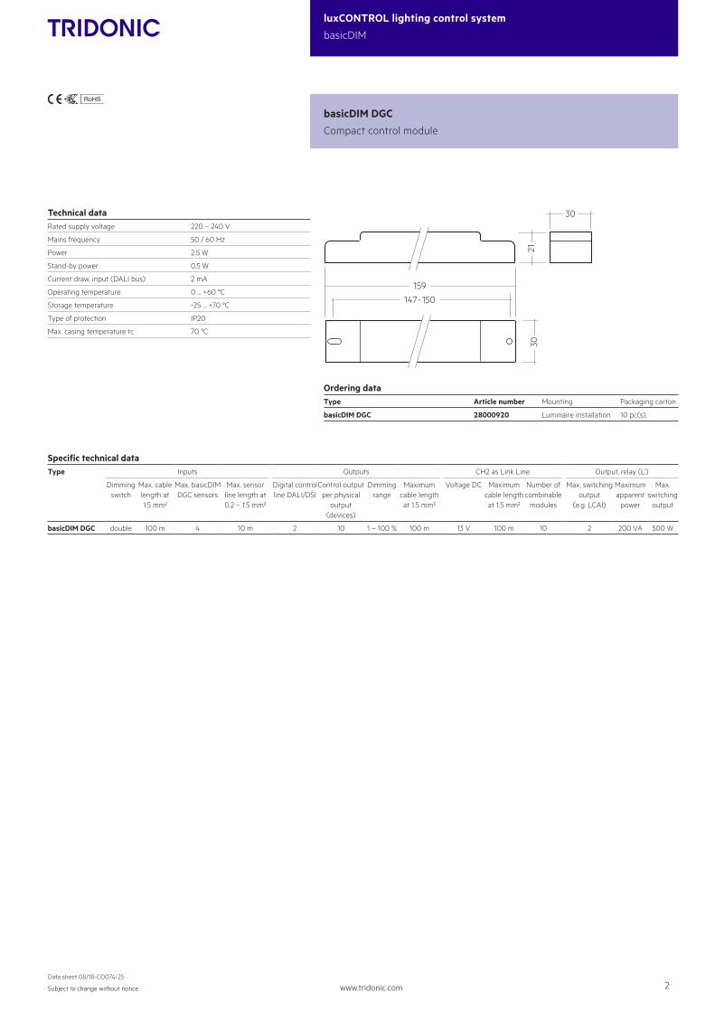
Technical dataRated supply voltage 220 – 240 V
Mains frequency 50 / 60 Hz
Power 2.5 W
Stand-by power 0.5 W
Current draw, input (DALI bus) 2 mA
Operating temperature 0 ... +60 °C
Storage temperature -25 ... +70 °C
Type of protection IP20
Max. casing temperature tc 70 °C
basicDIM DGC
Compact control module
159147–150
3021
30
Ordering dataType Article number Mounting Packaging carton
basicDIM DGC 28000920 Luminaire installation 10 pc(s).
Specific technical dataType Inputs Outputs CH2 as Link Line Output, relay (L‘)
Dimming switch
Max. cable length at 1.5 mm²
Max. basicDIM DGC sensors
Max. sensor line length at 0.2 – 1.5 mm²
Digital control line DALI/DSI
Control output per physical
output (devices)
Dimming range
Maximum cable length at 1.5 mm²
Voltage DC Maximum cable length at 1.5 mm²
Number of combinable
modules
Max. switching output
(e.g. LCAI)
Maximumapparent
power
Max. switching
output
basicDIM DGC double 100 m 4 10 m 2 10 1 – 100 % 100 m 13 V 100 m 10 2 200 VA 500 W
5DPI 14f Mounting Kit
ACC
ES-
SOR
IES
Ordering dataType Article number Packaging carton Weight per pc.
5DPI 14f mounting kit 28001558 100 pc(s). 0.004 kg
5DPI 14f mounting kit black 28001575 100 pc(s). 0.004 kg
www.tridonic.com 3Subject to change without notice.
Data sheet 08/18-CO074-25
luxCONTROL lighting control system
basicDIM
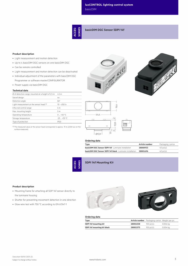
Product description
• Light measurement and motion detection
• Up to 4 basicDIM DGC sensors on one basicDIM DGC
• Can be remote controlled
• Light measurement and motion detection can be deactivated
• Individual adjustment of the parameters with basicDIM DGC
Programmer or software masterCONFIGURATOR
• Power supply via basicDIM DGC
Technical dataØ of detection range, mounted at a height of 2.5 m 4.5 m
Swivel design no
Detection angle 84°
Light measurement at the sensor head 1 10 – 650 lx
Infra-red control range 5 m
Max. mounting height 5 m
Operating temperature 0 ... +50 °C
Storage temperature -25 ... +55 °C
Type of protection IP20
basicDIM DGC Sensor 5DPI 14f
ACC
ES-
SOR
IES
44,4
Ø13,9
16,4
1,93
12,8
2
Ordering dataType Article number Packaging, carton
basicDIM DGC Sensor 5DPI 14f Luminaire installation 28000933 40 pc(s).
basicDIM DGC Sensor 5DPI 14f black Luminaire installation 28001696 40 pc(s).
1 The measured value at the sensor head corresponds to approx. 15 to 2,000 lux on the surface measured.
Product description
• Mounting frame for attaching all 5DP 14f sensor directly to
the luminaire housing
• Shutter for preventing movement detection in one direction
• Glow wire test with 750 °C according to EN 61347-1
5DPI 14f Mounting Kit
ACC
ES-
SOR
IES
Ordering dataType Article number Packaging carton Weight per pc.
5DPI 14f mounting kit 28001558 100 pc(s). 0.004 kg
5DPI 14f mounting kit black 28001575 100 pc(s). 0.004 kg
www.tridonic.com 4Subject to change without notice.
Data sheet 08/18-CO074-25
luxCONTROL lighting control system
basicDIM
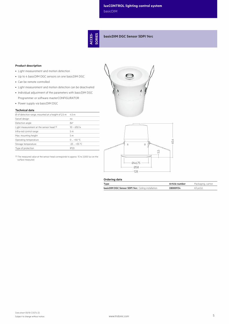
basicDIM DGC Sensor 5DPI 14rc
ACC
ES-
SOR
IES
65,4
5,5
Ø46,75Ø58128
Ordering dataType Article number Packaging, carton
basicDIM DGC Sensor 5DPI 14rc Ceiling installation 28000934 63 pc(s).
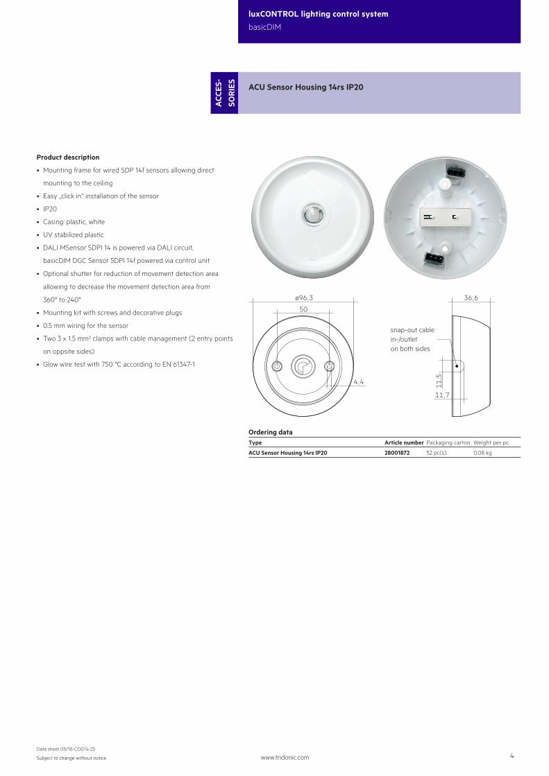
Product description
• Mounting frame for wired 5DP 14f sensors allowing direct
mounting to the ceiling
• Easy „click in“ installation of the sensor
• IP20
• Casing: plastic, white
• UV stabilized plastic
• DALI MSensor 5DPI 14 is powered via DALI circuit,
basicDIM DGC Sensor 5DPI 14f powered via control unit
• Optional shutter for reduction of movement detection area
allowing to decrease the movement detection area from
360° to 240°
• Mounting kit with screws and decorative plugs
• 0.5 mm wiring for the sensor
• Two 3 x 1.5 mm² clamps with cable management (2 entry points
on oppsite sides)
• Glow wire test with 750 °C according to EN 61347-1
ACU Sensor Housing 14rs IP20
ACC
ES-
SOR
IES
4,4
11,7
snap-out cablein-/outleton both sides
36,6
50
ø96,3
11,5
Ordering dataType Article number Packaging carton Weight per pc.
ACU Sensor Housing 14rs IP20 28001872 52 pc(s). 0.08 kg
www.tridonic.com 5Subject to change without notice.
Data sheet 08/18-CO074-25
luxCONTROL lighting control system
basicDIM
basicDIM DGC Sensor 5DPI 14rc
ACC
ES-
SOR
IES
65,4
5,5
Ø46,75Ø58128
Ordering dataType Article number Packaging, carton
basicDIM DGC Sensor 5DPI 14rc Ceiling installation 28000934 63 pc(s).
Product description
• Light measurement and motion detection
• Up to 4 basicDIM DGC sensors on one basicDIM DGC
• Can be remote controlled
• Light measurement and motion detection can be deactivated
• Individual adjustment of the parameters with basicDIM DGC
Programmer or software masterCONFIGURATOR
• Power supply via basicDIM DGC
Technical dataØ of detection range, mounted at a height of 2.5 m 4.5 m
Swivel design no
Detection angle 84°
Light measurement at the sensor head 1 10 – 650 lx
Infra-red control range 5 m
Max. mounting height 5 m
Operating temperature 0 ... +50 °C
Storage temperature -25 ... +55 °C
Type of protection IP20
1 The measured value at the sensor head corresponds to approx. 15 to 2,000 lux on the surface measured.
www.tridonic.com 6Subject to change without notice.
Data sheet 08/18-CO074-25
luxCONTROL lighting control system
basicDIM
REMOTECONTROL IR6
ACC
ES-
SOR
IES
Ordering dataType Article number Dimensions L x W x H Packaging carton
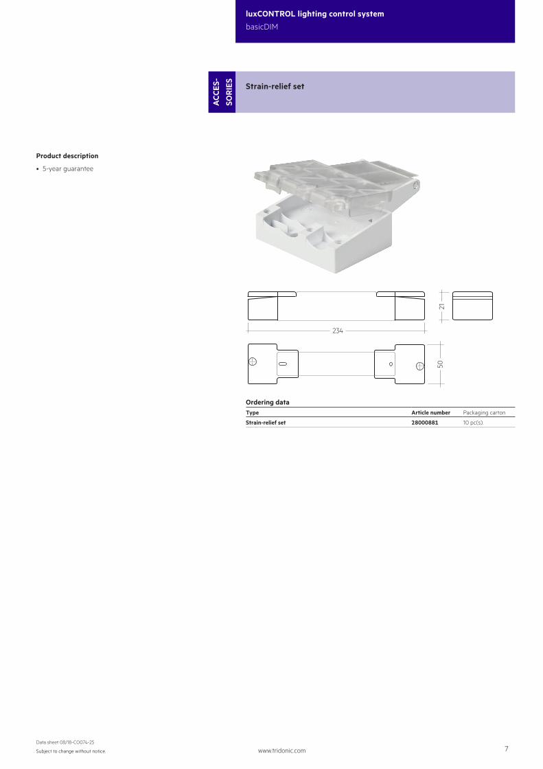
REMOTECONTROL IR6 28000647 86.5 x 40.5 x 7.2 mm 500 pc(s).
Product description
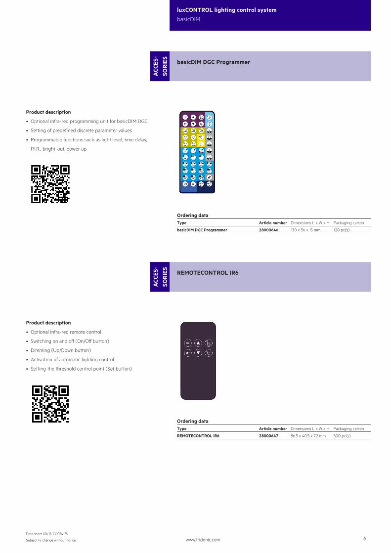
• Optional infra-red programming unit for basicDIM DGC
• Setting of predefined discrete parameter values
• Programmable functions such as light level, time delay,
P.I.R., bright-out, power up
basicDIM DGC Programmer
ACC
ES-
SOR
IES
Ordering dataType Article number Dimensions L x W x H Packaging carton
basicDIM DGC Programmer 28000646 130 x 56 x 15 mm 120 pc(s).
Product description
• Optional infra-red remote control
• Switching on and off (On/Off button)
• Dimming (Up/Down button)
• Activation of automatic lighting control
• Setting the threshold control point (Set button)
Strain-relief set
ACC
ES-
SOR
IES
21
234
50
Ordering dataType Article number Packaging carton
Strain-relief set 28000881 10 pc(s).
www.tridonic.com 7Subject to change without notice.
Data sheet 08/18-CO074-25
luxCONTROL lighting control system
basicDIM
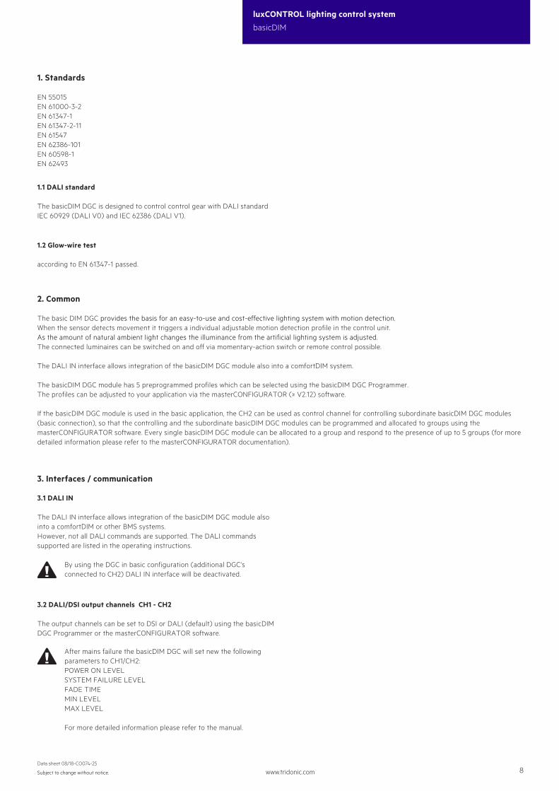
Strain-relief set
ACC
ES-
SOR
IES
21
234
50
Ordering dataType Article number Packaging carton
Strain-relief set 28000881 10 pc(s).
Product description
• 5-year guarantee
www.tridonic.com 8Subject to change without notice.
luxCONTROL lighting control system
basicDIM
Data sheet 08/18-CO074-25
1. Standards
EN 55015EN 61000-3-2EN 61347-1EN 61347-2-11EN 61547EN 62386-101 EN 60598-1EN 62493
2. Common
The basic DIM DGC provides the basis for an easy-to-use and cost-effective lighting system with motion detection.When the sensor detects movement it triggers a individual adjustable motion detection profile in the control unit.As the amount of natural ambient light changes the illuminance from the artificial lighting system is adjusted.The connected luminaires can be switched on and off via momentary-action switch or remote control possible.
The DALI IN interface allows integration of the basicDIM DGC module also into a comfortDIM system.
The basicDIM DGC module has 5 preprogrammed profiles which can be selected using the basicDIM DGC Programmer.The profiles can be adjusted to your application via the masterCONFIGURATOR (≥ V2.12) software.
If the basicDIM DGC module is used in the basic application, the CH2 can be used as control channel for controlling subordinate basicDIM DGC modules (basic connection), so that the controlling and the subordinate basicDIM DGC modules can be programmed and allocated to groups using the masterCONFIGURATOR software. Every single basicDIM DGC module can be allocated to a group and respond to the presence of up to 5 groups (for more detailed information please refer to the masterCONFIGURATOR documentation).
1.2 Glow-wire test
according to EN 61347-1 passed.
1.1 DALI standard
The basicDIM DGC is designed to control control gear with DALI standard IEC 60929 (DALI V0) and IEC 62386 (DALI V1).
3.1 DALI IN
The DALI IN interface allows integration of the basicDIM DGC module also into a comfortDIM or other BMS systems.However, not all DALI commands are supported. The DALI commands supported are listed in the operating instructions.
By using the DGC in basic configuration (additional DGC‘s connected to CH2) DALI IN interface will be deactivated.
3.2 DALI/DSI output channels CH1 - CH2
The output channels can be set to DSI or DALI (default) using the basicDIM DGC Programmer or the masterCONFIGURATOR software.
After mains failure the basicDIM DGC will set new the following parameters to CH1/CH2:POWER ON LEVELSYSTEM FAILURE LEVELFADE TIMEMIN LEVELMAX LEVEL
For more detailed information please refer to the manual.
3. Interfaces / communication
www.tridonic.com 9Subject to change without notice.
luxCONTROL lighting control system
basicDIM
Data sheet 08/18-CO074-25
4. Installation
• basicDIM DGC can be operated without sensor. The motion detection must be disabled via masterCONFIGURATOR or with unique connecting a sensor and basicDIM DGC Programmer.• DSI/DALI is not SELV. The installation instructions for mains voltage therefore apply.• The maximum cable length between the external switch and basicDIM DGC is 100 m.• The maximum cable length between the sensor and basicDIM DGC is 10 m.• A synchronous operation of DALI and DSI ballasts at the same control gear is not possible.• The output channels (for a cable cross-section of 1.5 mm2) must not be exceeded 100 m.• If CH2 is used as link line, the maximum cable length must not exceed 100 m (at 1.5 mm²).• If a basicDIM DGC is connected to CH2, DALI IN is disabled and CH2 is used as Link-Line (neighbourhood function). No control commands are transmitted via CH2, to reactivate
DALI IN see basicDIM DGC manual.
• Any number of push to make switches may be connected in parallel to the inputs.• Do not connect standard switches to the input.• Please ensure that the detection range of the sensor lies in the lighting area of the controlled luminaires.• Heaters, fans, printers and copiers located in the detection zone may cause incorrect presence detection.• To avoid false readings, the sensor should be installed so there is no direct light from the lamp in the detection zone.• Sensor wires must be routed separately from the lamp wires and mains cables otherwise the lighting control system may malfunction. If separate routing is not possible (for reasons of space) shielded lamp wires and mains cables must be used.
3.3 Switch
basicDIM DGC has two inputs (T1 and T2) for two external switches. Any number of switches can be connected in parallel to the inputs (parallel connection of T1 and T2 possible).
Short press (< 500 ms): ON/OFF
Long press (> 500 ms): Dim up/down A change in the light value deactivates lighting regulation only temporarily. As soon as the luminaire has been automatically switched on again (motion detection) or manually switched off and on again, regulation is activated again.
2 x short press: The overwritten setpoint light value is stored (luminaire acknowledges by flashing twice)Function is lockable via the DSI programmer
Different output channels are controlled, depending on the profile selected.

www.tridonic.com 10Subject to change without notice.
luxCONTROL lighting control system
basicDIM
Data sheet 08/18-CO074-25
4.1 Wiring diagram basicDIM DGC
DALI
basicDIM DGC
LNL’
T1T2
N
L
DA
DA
DADA
DADA
D1D2
D1D2CH1
CH2DADA
234
67
234
67
eD1eD2Sensor
basicDIM DGC Sensor
UconverterLCAI
DADA
DADA
234
67
234
67
DALI IN
max. 64 DGC
max. 500 W (L') max. 4
max. 10
max. 10
UconverterLCAI
UconverterLCAI
UconverterLCAI
* must be the same phase as for L
*
Relais in standby
basicDIM DGC
LNL’
T1T2
N
L
L’
DA
DA
DADA
DADA
D1D2
D1D2CH1
CH2DADA
234
67
234
67
eD1eD2Sensor
basicDIM DGC Sensor
DALI IN
max. 64 DGC
max. 4
max. 10
max. 10
UconverterLCAI
UconverterLCAI
The inrush currents of the control gearsmust be taken into account whendimensioning the contactor.
* must be the same phase as for L
*
www.tridonic.com 11Subject to change without notice.
luxCONTROL lighting control system
basicDIM
Data sheet 08/18-CO074-25
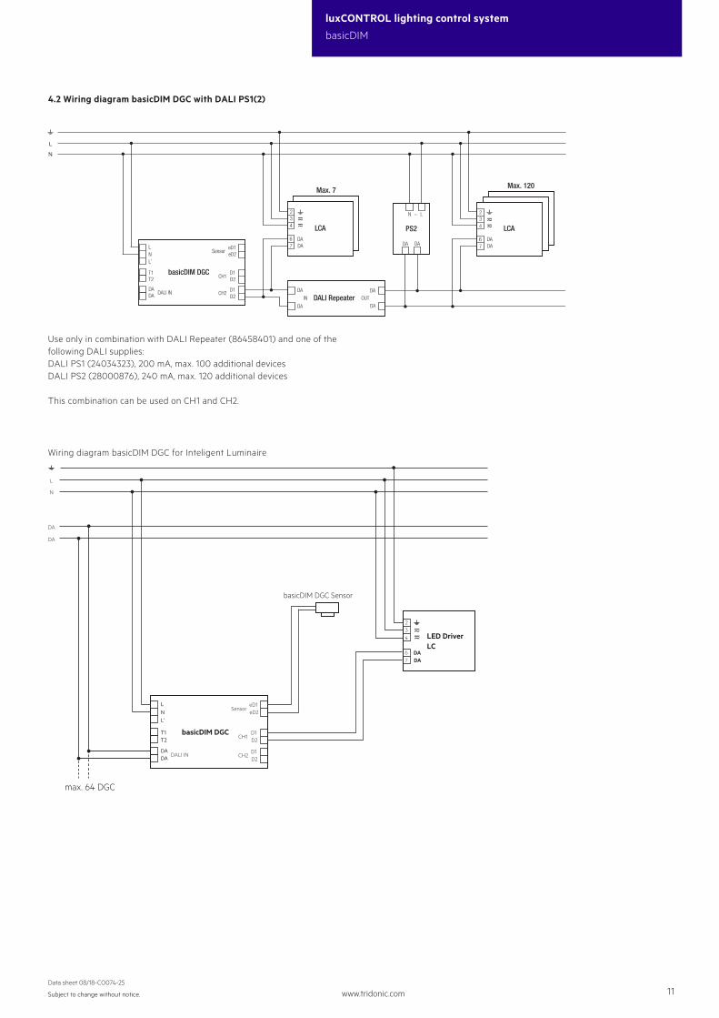
Wiring diagram basicDIM DGC for Inteligent Luminaire
basicDIM DGC
LNL’
T1T2
N
L
DA
DA
DADA
D1D2
D1D2
CH1
CH2DADA
234
67
eD1eD2
Sensor
basicDIM DGC Sensor
DALI IN
max. 64 DGC
LED DriverLC
N
L
LCADADA
DADA
LCA
234
67
234
67
DALI RepeaterDA
DA
DA
DAOUTIN
N L~
DA DA
Max. 7 Max. 120
PS2
basicDIM DGC
LNL’
T1T2
D1D2
D1D2CH1
CH2DADA
eD1eD2Sensor
DALI IN
4.2 Wiring diagram basicDIM DGC with DALI PS1(2)
Use only in combination with DALI Repeater (86458401) and one of the following DALI supplies:DALI PS1 (24034323), 200 mA, max. 100 additional devicesDALI PS2 (28000876), 240 mA, max. 120 additional devices
This combination can be used on CH1 and CH2.
www.tridonic.com 12Subject to change without notice.
luxCONTROL lighting control system
basicDIM
Data sheet 08/18-CO074-25
A1
B1 A1
C1B1B0
C1C0
A1 & A2
C0B0
SensorD1D2
D1D2D1D2
C0 C1
B0 B1
A1
A2
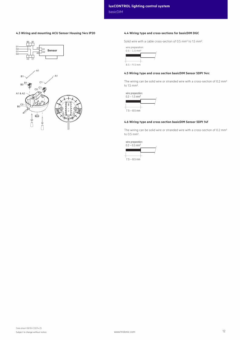
4.3 Wiring and mounting ACU Sensor Housing 14rs IP20
��� – ��� mm
wire preparation:��� – ��� mm²
4.4 Wiring type and cross-sections for basicDIM DGC
Solid wire with a cable cross-section of 0.5 mm² to 1.5 mm².
7.5 – 8.5 mm
wire preparation:0.2 – 1.5 mm²
4.5 Wiring type and cross section basicDIM Sensor 5DPI 14rc
The wiring can be solid wire or stranded wire with a cross-section of 0.2 mm² to 1.5 mm².
7.5 – 8.5 mm
wire preparation:0.2 – 0.5 mm²
4.6 Wiring type and cross section basicDIM Sensor 5DPI 14f
The wiring can be solid wire or stranded wire with a cross-section of 0.2 mm² to 0.5 mm².

www.tridonic.com 13Subject to change without notice.
luxCONTROL lighting control system
basicDIM
Data sheet 08/18-CO074-25
4.7 Mounting variants luminair installation sensor
Size of the sheet: 0.8 – 1.8 mm
ø14,
1+0,
2 0
1,5 – 2,5
Size of the sheet: 0.8 – 3.0 mm
Size of the sheet: 0.6 – 0.8 mm
3,2 0 -0,15
ø1,8 +0,1 0
20 +0,1 -0,1
4 +0,2 0
2,2+
0,2
0
19,1
41,1 +0,2 0
14,1
+0,
2 0
R1,9 0 -0,2
3,3 – 5,5
4.8 Mounting in luminaire housing with Mounting Kit:
Size of the sheet: 0.8 – 2.0 mm
Shutter support ring has to be snappedinto the shutter support
Thickness metal sheet 0.8 – 2.0 mm0.
8
Option shutter:has to be snappedinto the shutter support ring
Dimension drawing for neededmounting opening
10,65±0,05
1,8±
0,05
ø21,2+0,1
–0,0
R0,9
www.tridonic.com 14Subject to change without notice.
luxCONTROL lighting control system
basicDIM
Data sheet 08/18-CO074-25
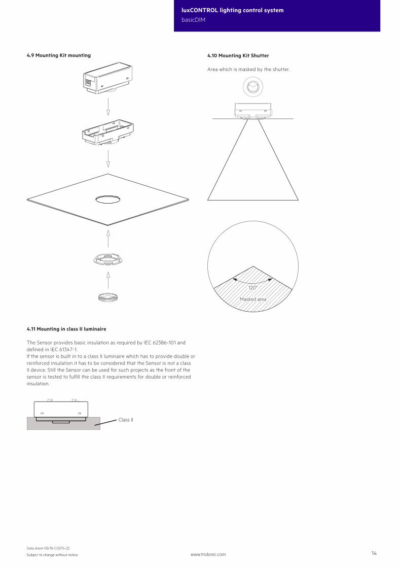
4.9 Mounting Kit mounting
120°
Masked area
4.10 Mounting Kit Shutter
Area which is masked by the shutter.
4.11 Mounting in class II luminaire
The Sensor provides basic insulation as required by IEC 62386-101 and defined in IEC 61347-1.If the sensor is built in to a class II luminaire which has to provide double or reinforced insulation it has to be considered that the Sensor is not a class II device. Still the Sensor can be used for such projects as the front of the sensor is tested to fulfill the class II requirements for double or reinforced insulation.
Class II
www.tridonic.com 15Subject to change without notice.
luxCONTROL lighting control system
basicDIM
Data sheet 08/18-CO074-25
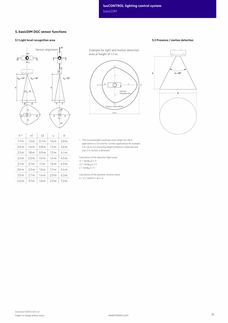
5. basicDIM DGC sensor functions
5.2 Presence / motion detection5.1 Light level recognition area
y
x1 yy
x1
αx1 = 38°αx2 = 22° αy = 30°
h
x2 x1
y y
y
y
yx2
x2
22° 38°
h
x2 x1
y y
x1
x2
Sensor alignment
* The recommended maximum room height for office
applications is 3 m and for corridor applications for example
4 m. Up to 2 m mounting height presence is detected and
over 2 m motion is detected.
Calculation of the diameter (light area):
x1 = tan(ax1) × hx2 = tan(ax2) × hy = tan(ay) × h
Calculation of the diameter (motion area):
d = 2 × tan(0,5 × a) × h
h * x1 x2 y d
1.7 m 1.3 m 0.7 m 1.0 m 3.0 m
2.0 m 1.6 m 0.8 m 1.2 m 3.6 m
2.3 m 1.8 m 0.9 m 1.3 m 4.1 m
2.5 m 2.0 m 1.0 m 1.4 m 4.5 m
2.7 m 2.1 m 1.1 m 1.6 m 4.9 m
3.0 m 2.3 m 1.2 m 1.7 m 5.4 m
3.5 m 2.7 m 1.4 m 2.0 m 6.3 m
4.0 m 3.1 m 1.6 m 2.3 m 7.2 m
x1
y
y
1 m
0.7 m
1 m
1.3 mx2
Light levelrecognation area
Presence / motion detection
3.0 m
Example for light and motion detection area at height of 1.7 m:
h α = 84°
d

www.tridonic.com 16Subject to change without notice.
luxCONTROL lighting control system
basicDIM
Data sheet 08/18-CO074-25
6. Functions
6.1 Relais
The relay can be used in four different operating modes:• Reduction of standby losses (standby wiring example)• Independent output channel for switching non-dimmable luminaires (DALI wiring example)
Depending on the profile used, the relay will respond differently. For the 5 main profiles, the two relay profiles used are Standby and OnlyOFF.The masterCONFIGURATOR software allows to enable or disable the relay profiles as well.
Standby
Standby
Energy saving mode If the basicDIM DGC module is switched off, the relay will switch off (after 10 minutes).If the basicDIM DGC is switched on, the relay will switch on.Switching: relay in standby mode
OnlyOFF
Only OFF
The relay must be switched on using the momentary-action switch, but is switched off by the presence detector.
Active The relay is switched on or off via the presence detector.
Inactive The relay must be switched on and off using the momentary-action switch.
Depending on the profile used, different operating modes are preprogrammed for the presence detector. These can be changed using the basicDIM DGC Programmer or the masterCONFIGURATOR software.
ON OFF
ON / OFF The light is switched on and off automatically based on the presence/absence of people.
only OFF
Only OFF The presence detector just switches the connected luminaires off. The luminaires are switched on manually via the connected external momentary-action switch or the remote control.
∞
Never OFF
If no presence is detected, the sensor dims down to the “second light level” parameter and maintains this setting.
OFF
OFF Presence detector disabled. The light must be switched on and off manually.
www.tridonic.com 17Subject to change without notice.
luxCONTROL lighting control system
basicDIM
Data sheet 08/18-CO074-25
6.2 Run-on time
1 min
10min
20min
AUTO
Run-on time of the presence detector, run-on time starts when no presence is detected.The run-on time may vary depending on the profile used.You can choose whether you want the basicDIM DGC module to switch off the light completely or to dim it down to the absence value after the run-on time.It can also be changed using the basicDIM DGC Programmer or the masterCONFIGURATOR software.
Absence value
1%
10%
30%
Switch-off delay
0min
1 min
30min ∞
The absence value (light level) and the switch-off delay (the period for which the level is maintained) differ depending on the profile used; these parameters may be changed using the basicDIM DGC Programmer or the masterCONFIGURATOR software.
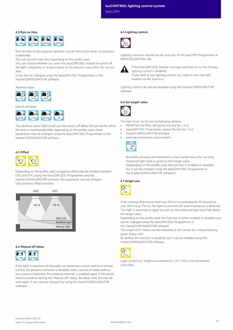
40 % 70 %
500 LUXArtificial light
Natural light
CH2 CH1
6.3 Offset
OFF
- 30%
Depending on the profile used, a negative offset may be enabled between CH2 and CH1. Using the basicDIM DGC Programmer and the masterCONFIGURATOR software, this parameter may be changed (also positive offset possible).
6.4 Manual-off delay
1 min
10 min
If the light is switched off manually via momentary-action switch or remote control, the presence detector is disabled. After a period of delay without any presence detected, the presence detector is enabled again. If the sensor detects presence during the “Manual Off” delay, the delay time will start all over again. It can only be changed by using the masterCONFIGURATOR software.
6.5 Lighting control
AUTO
Lighting control is started via the Auto key of the basicDIM Programmer or REMOTECONTROL IR6.
If the basicDIM DGC module has been switched on via the ON key, lighting control is disabled.If you want to use lighting control, you need to start the DGC module via the Auto key.
Lighting control can also be disabled using the masterCONFIGURATOR software.
6.6 Set target value
SET
The light level can be set via following options: • REMOTECONTROL IR6 (press the key for > 3 s)• basicDIM DGC Programmer (press the key for > 3 s)• masterCONFIGURATOR software• external momentary-action switch:
ON
SET
By briefly pressing the momentary-action switch twice the currently measured light level is saved as new target value. (Depending on the profile used, this function is enabled or disabled, but it can be changed using the basicDIM DGC Programmer or the masterCONFIGURATOR software)
6.7 Bright-out
ON
If the nominal illuminance level (e.g. 500 lx) is exceeded for 10 minutes at over 150 % (e.g. 750 lx), the light is switched off, even if presence is detected.The light is switched on again as soon as the measured light level falls below the target value.Depending on the profile used, this function is either enabled or disabled and can be changed using the basicDIM DGC Programmer or the masterCONFIGURATOR software.The bright-OUT status can be indicated on the sensor by a slowly flashing green status LED.By default this function is disabled, but it can be enabled using the masterCONFIGURATOR software.
CH1 ONCH2 OFF
Light control incl. brightout activated for CH1. CH2 is not illuminated controlled.

www.tridonic.com 18Subject to change without notice.
luxCONTROL lighting control system
basicDIM
Data sheet 08/18-CO074-25
T1Momentary-action switch 1
T2Momentary-action switch 2
CH1 CH2
CH1
CH2
Display of outputs controlled by momentary-action switch (CH1 and CH2, or just CH1 or CH2)
OFF
Switched off No response to presence detected in other groups. Default setting for all profiles!
ON
Switched on If presence is reported by other groups, the light level will switch to presence value
Switched on If presence is reported by other groups, the light level will switch to absence value
6.8 Neighbourhood function
Depending on the profile used, the basicDIM DGC can respond to presence detected in other groups. These functions can be changed using the basicDIM DGC Programmer or the masterCONFIGURATOR software.
6.9 Momentary-action switch inputs
6.10 Basic functions
ONSwitching onIf the DGC module has been switched on via ON, lighting control is disabled.
OFFSwitching off
Dimming up
Dimming down
6.12 Behaviour after return of power
The basicDIM DGC module features two different types of starting behaviour after mains failure.
OFF
Power ON behaviour OFF (luminaires remain switched off)
ON
Power ON behaviour ON (the luminaires are switched on after return of power).Default setting for all profiles!
6.11 Profiles
Profile 1: Individual room Profile 2: Classroom Profile 3: Corridor Profile 4: WC Profile 5: Free-standing luminaire (default profile)Profile Test:
You may use the Profile Test to check the profile you selected.All times relevant to the profile are reduced to 15 s.The Profile Test will automatically be terminated after 1 h, or by pressing the Auto key of the basicDIM DGC Programmer.
The profiles can be adjusted to your needs via the masterCONFIGURATOR software or the DGC Programmer.For more detailed information please refer to the masterCONFIGURATOR documentation at www.tridonic.com.

www.tridonic.com 19Subject to change without notice.
luxCONTROL lighting control system
basicDIM
Data sheet 08/18-CO074-25
7. Brief description of profiles
7.1 Individual room profile
7.2 Classroom profile
7.3 Corridor profile
7.4 WC profile
7.5 Free-standing luminaire profile (default)
T1
CH1
ON
OFF
ON
SET
Standby
ON
- 30%
ON OFF
10min
10%
1 min
10 min
T2
CH2
ON
OFF
ON
SET
T1
CH1 CH2
ON
OFF
Only OFF
ON
- 30%
only OFF
20min
10 min
T2
ON
OFF
T1
CH1 CH2
ON
OFF
Standby
ON
ON OFF
1 min
10%
∞ 1 min
T2
CH1 CH2
ON
T1
CH1 CH2
ON
OFF
Only OFF
CH1 ONCH2 OFF
ON OFF
20min
1 min
T2
ON
T1
CH1
ON
OFF
ON
SET
Standby
CH1 ONCH2 OFF
ON OFF
10min
10%
1 min
10 min
T2
CH2
ON
OFF
ON
SET
www.tridonic.com 20Subject to change without notice.
luxCONTROL lighting control system
basicDIM
Data sheet 08/18-CO074-25
8. Miscellaneous
8.1 Additional information
Additional technical information at www.tridonic.com → Technical Data
Guarantee conditions at www.tridonic.com → Services
Life-time declarations are informative and represent no warranty claim.No warranty if device was opened.