Embed Size (px)
Citation preview
Specif icat ion Submittal page
Job Name:
Job Number:
Model Numbers:
369974a 1 11.05.15
ThermostatL-HWLV2-WIFILutronR
LutronR Wireless Thermostat
The LutronR Wireless Thermostat allows for the ability to adjust heating and cooling systems from anywhere using your mobile device – whether home or away. The LutronR Wireless Thermostat works with CasétaR Wireless, RadioRAR 2, and HomeWorksR QS.
Features
• Powered by HoneywellR HVAC control technology.
• Works with CasetaR Wireless1, RadioRAR 22, or HomeWorksR QS2.
• Adjust temperature settings via mobile device – whether home or away.
• 7-day programmable schedule.
• Large touchscreen display with backlight and message center.
• For use with an existing Wi-Fi Network.
• Supports up to three heat and two cool stages (heat pump), or up to two heat and two cool stages (conventional).
• Controls humidification, dehumidification, or ventilation.
• Universal input for a wired indoor, outdoor, or discharge sensor.
• Keeps date/time during power failure and automatically adjusts for daylight savings time.
• Automatically downloads software updates.
• Requires 24 V~ common connection from the HVAC equipment.
• Residential or commercial use.
LutronR Wireless Thermostat
1 The LutronR App, LutronR Smart Bridge or Smart Bridge PRO, and HoneywellR Total Connect Comfort account is required for setup and use with CasétaR Wireless. The LutronR App is compatible with iOSR and AndroidT devices.
2 The LutronR Connect app, LutronR Connect Bridge, and a HoneywellR Total Connect Comfort account is required for setup and use with RadioRAR 2 and HomeWorksR QS. The LutronR Connect app is compatible with iOSR and AndroidT devices.
iOS is a registered trademark of Cisco in the U.S. and other countries and is used under license. Android is a trademark of Google Inc.
Specif icat ion Submittal page
Job Name:
Job Number:
Model Numbers:
369974a 2 11.05.15
ThermostatL-HWLV2-WIFILutronR
Regulatory Approvals
• FCC• IC
Power
• Operating voltage: 24 V~ IEC PELV / NECR Class 2
Typical Power Consumption
• 2.35 VA (backlight on)
Environment
• Ambient operating temperature: 32 ºF to 120 ºF (0 ºC to 49 ºC) 5% to 90% humidity, non-condensing. Indoor use only.
Communication
• LutronR Wireless Thermostat communicates via a connection to an existing Wi-Fi network, and must be located within range of the Wi-Fi router.
• Supports 802.11 B/G/N wireless routers.
Power Failure
• Power failure memory: should power be interrupted, the LutronR Wireless Thermostat will retain its programming when power is restored.
Mounting
• Mount on a wall using conventional thermostat mounting methods.
Wiring
• IEC PELV / NECR Class 2, 22 AWG (0.5 mm2) to 18 AWG (0.75 mm2) solid wiring. Requires transformer common connection.
Warranty
• www.lutron.com/TechnicalDocumentLibrary/369-119_Wallbox_Warranty.pdf
• Warranty only valid if installed by a properly trained climate control specialist.
Specifications
Specif icat ion Submittal page
Job Name:
Job Number:
Model Numbers:
369974a 3 11.05.15
ThermostatL-HWLV2-WIFILutronR
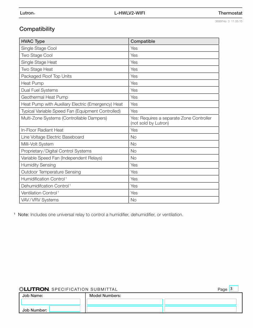
Compatibility
HVAC Type Compatible
Single Stage Cool Yes
Two Stage Cool Yes
Single Stage Heat Yes
Two Stage Heat Yes
Packaged Roof Top Units Yes
Heat Pump Yes
Dual Fuel Systems Yes
Geothermal Heat Pump Yes
Heat Pump with Auxiliary Electric (Emergency) Heat Yes
Typical Variable Speed Fan (Equipment Controlled) Yes
Multi-Zone Systems (Controllable Dampers) Yes: Requires a separate Zone Controller (not sold by Lutron)
In-Floor Radiant Heat Yes
Line Voltage Electric Baseboard No
Milli-Volt System No
Proprietary / Digital Control Systems No
Variable Speed Fan (Independent Relays) No
Humidity Sensing Yes
Outdoor Temperature Sensing Yes
Humidification Control 1 Yes
Dehumidifcation Control 1 Yes
Ventilation Control 1 Yes
VAV / VRV Systems No
1 Note: Includes one universal relay to control a humidifier, dehumidifier, or ventilation.

Specif icat ion Submittal page
Job Name:
Job Number:
Model Numbers:
369974a 4 11.05.15
ThermostatL-HWLV2-WIFILutronR
DimensionsAll dimensions are shown as unless otherwise noted.in
(mm)
Front View Side View
4 5⁄8(118)
4 15⁄16
(126) 1 1⁄8(29)
3 5⁄16
(84)
Back View
Specif icat ion Submittal page
Job Name:
Job Number:
Model Numbers:
369974a 5 11.05.15
ThermostatL-HWLV2-WIFILutronR
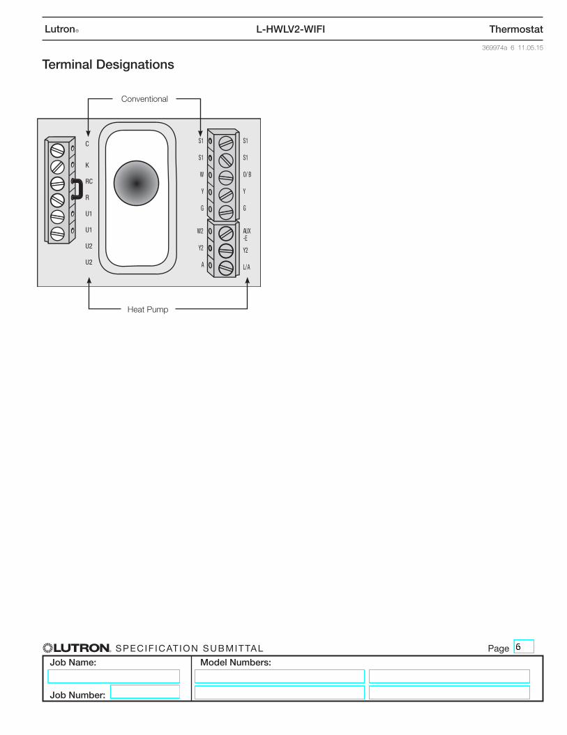
S1
S1
W
Y
G
W2
Y2
A
CK
R C
RU1U1U2U2
S1
S1
O/B
Y
GAU X
-EY2L/A
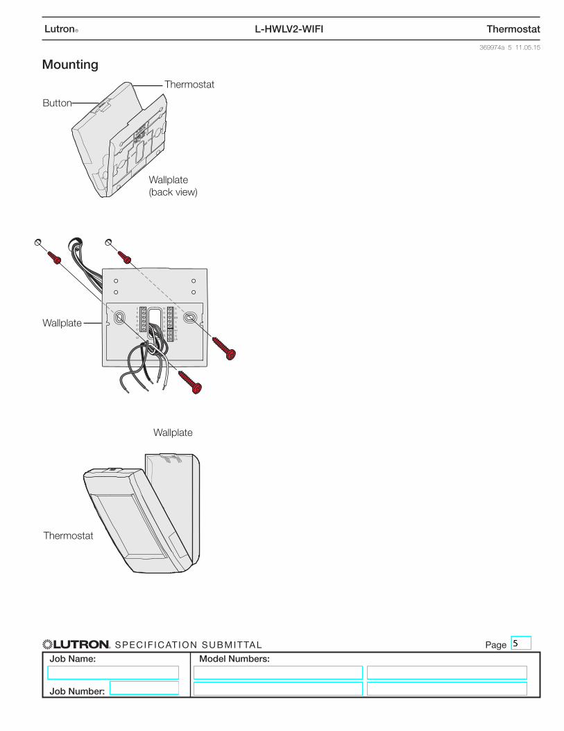
Mounting
Thermostat
Wallplate(back view)
Button
Wallplate
Wallplate
Thermostat
Specif icat ion Submittal page
Job Name:
Job Number:
Model Numbers:
369974a 6 11.05.15
ThermostatL-HWLV2-WIFILutronR
Terminal Designations
S1
S1
W
Y
G
W2
Y2
A
S1
S1
O/ B
Y
G
AUX-E
Y2
L/A
K
RC
R
U1
U1
U2
U2
C
Conventional
Heat Pump
Specif icat ion Submittal page
Job Name:
Job Number:
Model Numbers:
369974a 7 11.05.15
ThermostatL-HWLV2-WIFILutronR
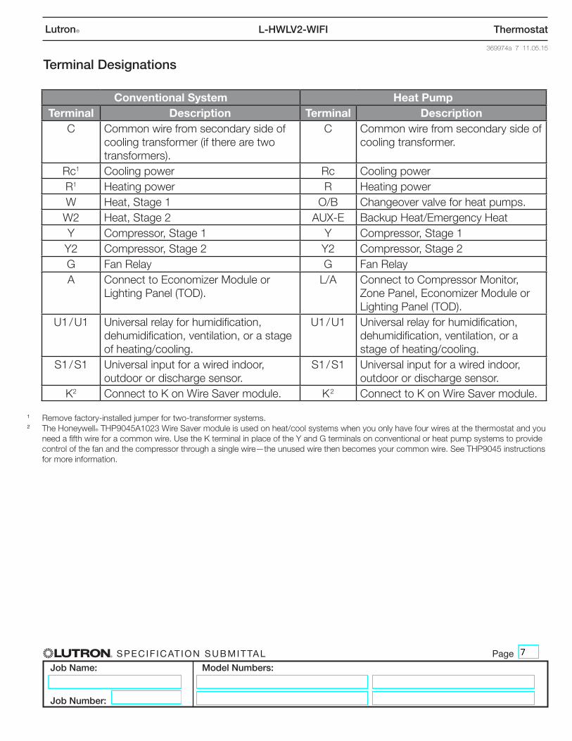
Conventional System Heat PumpTerminal Description Terminal Description
C Common wire from secondary side of cooling transformer (if there are two transformers).
C Common wire from secondary side of cooling transformer.
Rc1 Cooling power Rc Cooling powerR1 Heating power R Heating powerW Heat, Stage 1 O/B Changeover valve for heat pumps.W2 Heat, Stage 2 AUX-E Backup Heat/Emergency HeatY Compressor, Stage 1 Y Compressor, Stage 1Y2 Compressor, Stage 2 Y2 Compressor, Stage 2G Fan Relay G Fan RelayA Connect to Economizer Module or
Lighting Panel (TOD). L/A Connect to Compressor Monitor,
Zone Panel, Economizer Module or Lighting Panel (TOD).
U1 / U1 Universal relay for humidification, dehumidification, ventilation, or a stage of heating/cooling.
U1 / U1 Universal relay for humidification, dehumidification, ventilation, or a stage of heating/cooling.
S1 / S1 Universal input for a wired indoor, outdoor or discharge sensor.
S1 / S1 Universal input for a wired indoor, outdoor or discharge sensor.
K2 Connect to K on Wire Saver module. K 2 Connect to K on Wire Saver module.
1 Remove factory-installed jumper for two-transformer systems.2 The HoneywellR THP9045A1023 Wire Saver module is used on heat/cool systems when you only have four wires at the thermostat and you
need a fifth wire for a common wire. Use the K terminal in place of the Y and G terminals on conventional or heat pump systems to provide control of the fan and the compressor through a single wire—the unused wire then becomes your common wire. See THP9045 instructions for more information.
Terminal Designations
Specif icat ion Submittal page
Job Name:
Job Number:
Model Numbers:
369974a 8 11.05.15
ThermostatL-HWLV2-WIFILutronR
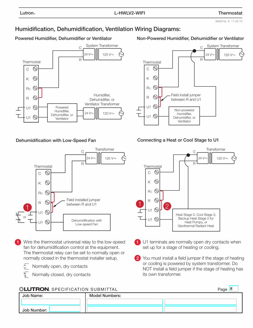
Humidification, Dehumidification, Ventilation Wiring Diagrams:
Wire the thermostat universal relay to the low-speed fan for dehumidification control at the equipment. The thermostat relay can be set to normally open or normally closed in the thermostat installer setup.
U1 terminals are normally open dry contacts when set up for a stage of heating or cooling.
You must install a field jumper if the stage of heating or cooling is powered by system transformer. Do NOT install a field jumper if the stage of heating has its own transformer.
1 1
2
Normally open, dry contacts
Normally closed, dry contacts
Powered Humidifier, Dehumidifier or Ventilator Non-Powered Humidifier, Dehumidifier or Ventilator
Connecting a Heat or Cool Stage to U1 Dehumidification with Low-Speed Fan
C
K
RC
R
U1
U1
C
R
C
K
RC
R
U1
U1
C
R
1 1
2
1
C
K
RC
R
U1
U1
C
R
OR
2
C
K
RC
R
U1
U1
C
R
1
System Transformer
Humidifier, Dehumidifier, or
Ventilator Transformer
Thermostat
Powered Humidifier,
Dehumidifier, or Ventilator
120 V~24 V~
120 V~24 V~
C
K
RC
R
U1
U1
C
R
C
K
RC
R
U1
U1
C
R
1 1
2
1
C
K
RC
R
U1
U1
C
R
OR
2
C
K
RC
R
U1
U1
C
R
1
System Transformer
Thermostat
Non-powered Humidifier,
Dehumidifier, or Ventilator
120 V~24 V~
Field install jumper between R and U1
C
K
RC
R
U1
U1
C
R
C
K
RC
R
U1
U1
C
R
1 1
2
1
C
K
RC
R
U1
U1
C
R
OR
2
C
K
RC
R
U1
U1
C
R
1
Transformer
Thermostat
Dehumidification with Low-speed Fan
120 V~24 V~
Field installed jumper between R and U1
or
C
K
RC
R
U1
U1
C
R
C
K
RC
R
U1
U1
C
R
1 1
2
1
C
K
RC
R
U1
U1
C
R
OR
2
C
K
RC
R
U1
U1
C
R
1
Transformer
Thermostat
Heat Stage 3, Cool Stage 3, Backup Heat Stage 2 for
Heat Pumps, or Geothermal Radiant Heat
120 V~24 V~
Specif icat ion Submittal page
Job Name:
Job Number:
Model Numbers:
369974a 9 11.05.15
ThermostatL-HWLV2-WIFILutronR
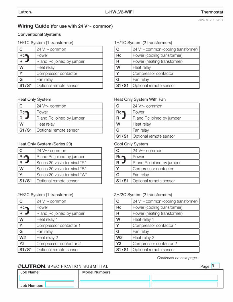
Conventional Systems
1H/1C System (1 transformer) 1H/1C System (2 transformers)
Heat Only System Heat Only System With Fan
Heat Only System (Series 20) Cool Only System
2H/2C System (1 transformer) 2H/2C System (2 transformers)
Wiring Guide (for use with 24 V~ common)
Continued on next page...
C 24 V~ commonRc PowerR R and Rc joined by jumperW Heat relayY Compressor contactorG Fan relayS1 / S1 Optional remote sensor
C 24 V~ common (cooling transformer)Rc Power (cooling transformer)R Power (heating transformer)W Heat relayY Compressor contactorG Fan relayS1 / S1 Optional remote sensor
C 24 V~ commonRc PowerR R and Rc joined by jumperW Heat relayS1 / S1 Optional remote sensor
C 24 V~ commonRc PowerR R and Rc joined by jumperW Heat relayG Fan relayS1 / S1 Optional remote sensor
C 24 V~ commonRc R and Rc joined by jumperR Series 20 valve terminal “R”W Series 20 valve terminal “B”Y Series 20 valve terminal “W”S1 / S1 Optional remote sensor
C 24 V~ commonRc PowerR R and Rc joined by jumperY Compressor contactorG Fan relayS1 / S1 Optional remote sensor
C 24 V~ commonRc PowerR R and Rc joined by jumperW Heat relay 1Y Compressor contactor 1G Fan relayW2 Heat relay 2Y2 Compressor contactor 2 S1 / S1 Optional remote sensor
C 24 V~ common (cooling transformer)Rc Power (cooling transformer)R Power (heating transformer)W Heat relay 1Y Compressor contactor 1G Fan relayW2 Heat relay 2Y2 Compressor contactor 2S1 / S1 Optional remote sensor
Specif icat ion Submittal page
Job Name:
Job Number:
Model Numbers:
369974a 10 11.05.15
ThermostatL-HWLV2-WIFILutronR
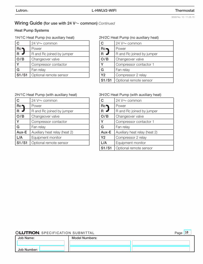
1H/1C Heat Pump (no auxiliary heat) 2H/2C Heat Pump (no auxiliary heat)
2H/1C Heat Pump (with auxiliary heat) 3H/2C Heat Pump (with auxiliary heat)
C 24 V~ commonRc PowerR R and Rc joined by jumperO / B Changeover valveY Compressor contactorG Fan relayS1 / S1 Optional remote sensor
C 24 V~ commonRc PowerR R and Rc joined by jumperO / B Changeover valveY Compressor contactor 1G Fan relayY2 Compressor 2 relayS1 / S1 Optional remote sensor
C 24 V~ commonRc PowerR R and Rc joined by jumperO / B Changeover valveY Compressor contactorG Fan relayAux-E Auxiliary heat relay (heat 2)L/A Equipment monitorS1 / S1 Optional remote sensor
C 24 V~ commonRc PowerR R and Rc joined by jumperO / B Changeover valveY Compressor contactor 1G Fan relayAux-E Auxiliary heat relay (heat 2)Y2 Compressor 2 relayL/A Equipment monitorS1 / S1 Optional remote sensor
Heat Pump Systems
Wiring Guide (for use with 24 V~ common) Continued
Specif icat ion Submittal page
Job Name:
Job Number:
Model Numbers:
369974a 11 11.05.15
ThermostatL-HWLV2-WIFILutronR
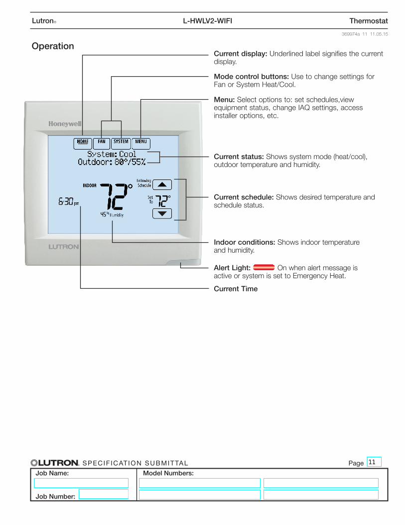
Current display: Underlined label signifies the current display.
Operation
Mode control buttons: Use to change settings for Fan or System Heat/Cool.
Menu: Select options to: set schedules,view equipment status, change IAQ settings, access installer options, etc.
Current status: Shows system mode (heat/cool), outdoor temperature and humidity.
Current schedule: Shows desired temperature and schedule status.
Indoor conditions: Shows indoor temperature and humidity.
Alert Light: On when alert message is active or system is set to Emergency Heat.
Current Time