Embed Size (px)
Citation preview
Prestressed Concrete Ties in North America
Russell H. Lutch1, Devin K. Harris2 and Theresa M. Ahlborn3
1Graduate Research Assistant, Michigan Technological University, Department of Civil and
Environmental Engineering, 1400 Townsend Drive, Houghton, Michigan, 49931; PH (906) 370-
4265; email: [email protected]
2 Assistant Professor, Michigan Technological University, Department of Civil and
Environmental Engineering, 1400 Townsend Drive, Houghton, Michigan, 49931;
PH (906) 487-3521; email: [email protected]
3Associate Professor, Michigan Technological University, Department of Civil and
Environmental Engineering, 1400 Townsend Drive, Houghton, Michigan, 49931;
PH (906) 487-2625; email: [email protected]
Word Count: 7,396
© AREMA 2009 ®
ABSTRACT
Approximately two million concrete railroad ties are installed annually in North America. The
introduction of concrete railroad ties increased durability and capacity when compared to the
typical wooden tie, which has historically been the standard in the railroad industry. It was not
until the early 1970s that concrete ties were utilized on large scale projects in North America.
The primary reason for the initial avoidance of this new technology was that the designs
originally adopted from Europe were simply not sized for the larger loads of the North American
track system. Following the involvement of the Portland Cement Association (PCA) during the
early 1970s, standards and designs were created for new concrete ties suited for use on North
America’s transit and heavy haul railroad systems.
Unlike wooden ties, concrete ties require considerable amounts of engineering and a relatively
complicated fabrication process. The reason for this is the prestressing steel integrated into the
design of the tie. Currently research to improve performance and durability is the field of
interest.
This paper focuses primarily on the state-of-art of concrete ties including design considerations,
failure mechanisms, durability, fabrication, economics and industry utilization with an emphasis
on cold regions applications as it pertains to the proposed Alaska Canada Rail Link. The
investigation includes a synthesis of the best practices used worldwide related to concrete ties
with the objective of enhancing the application of concrete ties in North America.
© AREMA 2009 ®

INTRODUCTION
Today the use of concrete ties is on the rise in North America as they become an economically
competitive alternative to the historical industry standard wood ties, while providing
performance which exceeds its competition in terms of durability and capacity. Issues of
adequacy in regards to flexural capacity and concrete durability were experienced during the
early years of concrete ties in North America. However, with the aid of the Portland Cement
Association (PCA) suitable designs capable of withstanding the tremendous loads of North
American railroads were developed during the 1970’s [1]. Since that time concrete ties have
developed into an adaptable tie alternative with applications in both transit and heavy haul rail
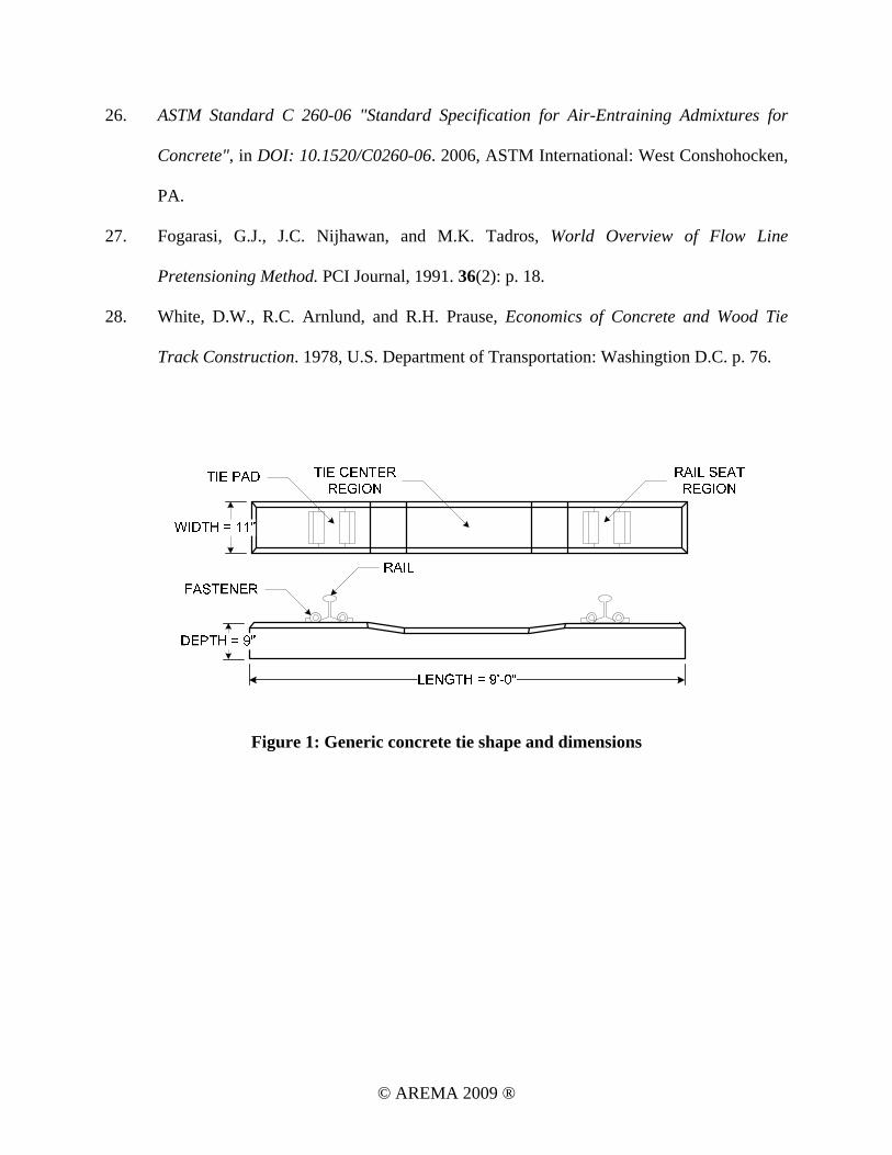
lines. The generic shape and dimensions of a typical North American concrete tie is illustrated
in Figure 1. As energy costs continue to increase and transportation on the North American
continent evolves, railroads will see a swell in demand therefore increasing the concrete tie
demand.
To achieve the performance exhibited by concrete ties considerable amounts of engineering have
been employed with respect to materials and design. The interaction between the concrete and
prestressing provides the necessary strength to resist the cyclic loading of the trains while
concrete provides the protection and rigidity to hold the system together. Initially, this
relationship was not well refined and failures were often the result of inadequate development of
prestressing steel and insufficient flexural capacity. However, over the last several decades tie
failures due to flexure and inadequate development have been nearly eliminated [2]. Currently
the focus of the rail industry is to improve tie durability and service life. Additionally, the
application of concrete ties in unique environments such as permafrost is of interest.
© AREMA 2009 ®
RESEARCH SIGNIFICANCE
This work focuses on the application and potential challenges of using prestressed concrete ties
for the Alaska Canada Rail Link (ACRL) expansion project. The proposed 1300 mile expansion
of heavy haul mainline track will link the mineral deposits of interior portions of Alaska, the
Yukon Territory and British Columbia with ports on the Pacific Rim. A secondary goal of the
project is to connect the Alaska Railroad to the continuous forty eight states [3]. A map showing
the proposed working alignment is shown in Figure 2.
A major obstacle for this project is the presence of permafrost and potential for heavy frost heave
that exists on large sections of the proposed track. This frost heave could be detrimental to the
track structure, especially the concrete ties. As a result, the evaluation of the designs and
fastening systems is necessary to determine the feasibility of construction and the expected
service life of a critical component of this track expansion. A thorough investigation is expected
to highlight other critical considerations related to concrete ties in prolonged freeze-thaw cycle
environments.
TIES IN PERMAFROST REGIONS
Permafrost is the term given to soil that is frozen for a period of time greater than two years.
Approximately 20 percent of the Earth’s land mass is covered by permafrost [4]. Undisturbed
permafrost is rather stable, but when structures or foundations are built upon it, freeze-thaw
cycles and uneven settling can begin causing frost up-heave in the soil. Railroads and other
structures built on permafrost are often plagued with up-heave as a result of the freeze-thaw
cycles of the permafrost [5]. Such a lesson was learned by the builders of the Copper River
Northwestern Railroad in south-central Alaska; uneven settling and frost up-heave on the
© AREMA 2009 ®

magnitude of feet lead a section of track to be called the “roller coaster railroad,” which
ultimately lead to the abandonment of the track.
The concept of using concrete ties in permafrost regions is not new, however information
regarding proper track structure and the effects of the heavy frost heave on concrete ties over
long periods of time is unknown. Several test tracks using concrete ties were built by the Federal
Railroad Administration (FRA) during the fall of 1973 along the Alaska Railroad. The
performance of the concrete ties was satisfactory in terms of failure rates and track geometry
performance, but little information about the ties was documented because the objective of the
test tracks was to study the effects of heavy frost heave on track structure and geometry [6].
Since this study, no new evaluations of the performance of concrete ties on permafrost have been
performed.
The use of concrete ties in permafrost regions outside of North America has been documented in
areas of Northern Scandinavia on the Malmbanan and Ofoten railways, Eastern Russia on the
Trans-Siberian Railway and recently Tibet during the construction of the Qinghai-Tibet railway
[7]. On these railways, concrete ties have shown to provide superior track rigidity and be capable
of withstanding the extreme climatic conditions.
MATERIALS
Typical to any prestressed concrete member are early high strength concrete and high tensile
strength steel [8]. In addition to the concrete and prestressing steel, tie fasteners and pads are
integral to the concrete tie. However, it should be noted that the application of these connection
devices is dictated by the railroad operators and their design is outside of the scope of the tie
© AREMA 2009 ®
manufacturer responsibilities. This presents a unique challenge because a component failure is
often considered a tie failure.
Concrete
The use of high strength concrete is necessary in the production of concrete ties due to the use of
prestressing. It is generally suggested that a minimum compressive strength of 7,000 psi at 28
days be used [9]. Reasons for high early strength concrete are the following:
• To efficiently produce concrete ties or any prestressed member for that matter the
prestressing force must be transferred to the tie at an early age. A compressive strength of
4,500 psi is typically considered satisfactory for prestressing load transfer.
• High early strength concrete allows beds to be turned over more rapidly due to shorter
release times.
Other considerations related to concrete mixture include admixtures. In order to achieve early
high strength concrete, manufacturers commonly include accelerator and water reducer
admixtures. Accelerators increase the rate or cement hydration while water reducers allow for
workability of the concrete at low water-cement ratios [10]. For areas of permafrost or severe
freeze-thaw cycles, air-entraining mixtures should be used. This relates to the fact that concrete
with entrained air is more durable with respect to freeze-thaw cycles.
Prestressing Tendons
Along with concrete, prestressing tendons give ties the tensile resistance required to support the
flexural forces imparted by the trains. During the initial days of concrete tie fabrication, when the
concrete is only at a fraction of its design strength, the most difficult issues to satisfy are
prestressing bond and allowable stresses of the concrete in tension [1, 11]. However, bond and
© AREMA 2009 ®

stress issues during the fabrication process have been solved by using smaller tendon diameters
and larger numbers of tendons set in a uniform pattern to avoid tension stresses at prestressing
transfer [12].
Prestressing may consist of either the typical 7-wire strand found in most prestressed concrete
fabrication or steel wire (Figure 3). Dimensions of 7-wire strand vary with the most common
among North American manufacturers being 3/8 in. diameter. Size of wire used over the years
has varied from 0.19 in. to 0.21 in. (4.80 mm to 5.32 mm). Due to manufacturers achieving better
bond between concrete and prestressing, the strand diameter has increased while maintaining the
same development length and therefore length of tie. This has also decreased the number of
wires required per tie, with the larger wires providing increased tensile resistance. Unlike
conventional reinforced concrete, high strength steel is required to resist the applied prestressing
forces. An ultimate strength of 260 ksi is common for wire whereas 7-wire strand typically has
an ultimate strength of 270.
The choice to use either 7-wire strand or individual wire is up to manufactures and is dictated by
design and material efficiency. However, wire prestressing offers several advantages over
conventional twisted multi-wire strand. Using wire provides the ability to change the quantity of
steel within the tie by smaller increments compared to 7-wire strands. Therefore, the ties can be
more efficiently designed to parameters dictated by predicted service loads, decreasing excess
material, in turn decreasing the cost of the tie [11]. Similarly, wire requires a shorter length for
development, resulting in a shorter tie to achieve the appropriate flexural strength.
© AREMA 2009 ®

Attachment Components
Tie Pads
Tie pads are installed between the rail and concrete ties to minimize water intrusion and tie
abrasion of the rail seat area. Pads also reduce impact and vibration effects on the track structure
leading to quieter operation [9]. Tie pads come in a variety of materials and configurations. Steel
and polymers are the most common materials used in tie pads. A common pad configuration will
include a polymer top pad, a steel plate for added rigidity, and a rubber gasket between the steel
plate and concrete tie to decrease sound, vibrations and water intrusion. Pads can also be made
solely of steel or polymeric materials [9].
Fasteners
In addition to the primary tie components of concrete and steel, fasteners are essential to attach
the steel rail to the tie and protect the tie from rail movement. The fastener type used is dictated
by the railroad operator and the tie application. Most fasteners are composed of two or three
parts; the ductile iron shoulder, spring clip, and insulator. The ductile iron shoulder is cast into
the tie during tie fabrication and varies in terms of size and embedment depth depending on the
fastening system used and tie application (Figure 4).
Fasteners are divided into two categories; captive and non-captive. The difference is in how and
when fastener parts are attached to the tie. Non-captive fasteners include those where only the
ductile iron shoulder is attached to the tie prior to shipping and tie installation (Figure 5). Captive
systems have all parts, shoulder, spring clip and insulator, installed prior to shipment and
installation (Figure 6). Captive systems are at risk of damage to the fastener during transportation
© AREMA 2009 ®
and installation, whereas non-captive systems require additional labor and time for component
installation once the tie is placed within the track.
FAILURE MECHANISMS
The three primary failure mechanisms of concrete ties observed by the rail industry today are rail
seat abrasion, flexural cracking from center binding and rail fastener failure [13, 14]. Of these
three, rail seat abrasion is the most common and difficult to prevent. Failures may be related to
concrete tie materials, design or a combination of the two. Installation and maintenance practices
also contribute to a tie’s resistance to these failure mechanisms. A discussion of the three
primary failure mechanisms is presented in the following sections.
Rail Seat Abrasion
The most common failure mode in the modern prestressed concrete railroad tie is rail seat
abrasion. Rail seat abrasion is the gradual wearing away of the cement paste from the concrete,
resulting in an uneven aggregate bearing surface beneath the tie pad [14]. Figure 7 illustrates the
abraded surface of a degraded rail set. Factors contributing to rail seat abrasion include: the
presence of water, high tonnage (static wheel loads larger than 25,000 lbs), steep track grades,
and especially track curves greater than two degrees [1]. Regions with freeze-thaw cycles often
experience rail seat abrasion at an accelerated rate due to increased cement paste deterioration
below the tie pad.
To prevent rail seat abrasion and prolong tie life, concrete tie manufactures have investigated
methods to protect concrete in the rail seat region. Research has focused on the application of
abrasion resistant materials applied in the form of pads, adhesive polymers (epoxy and
© AREMA 2009 ®
polyurethane) or cast-in-place plates in the rail seat region. Some industry techniques used to
mitigate rail seat abrasion to date include:
• Epoxy or polyurethane applied to rail seat shortly after casting [15],
• Cast-in-place steel plates [16],
• 3-part abrasion resistant pad assembly [16].
Of these options, epoxy or polyurethane has shown promising short term results and appears to
have gained acceptance among manufacturers and railroads. However, epoxy and polyurethane
do wear down over time allowing rail seat abrasion to take place. For rail seat abrasion repair
operations, the application of epoxy is common, but requires specific temperature and humidity
control and also results in costly track closures [15]. Testing of cast-in-place steel plates has
shown no rail seat abrasion at 4 times the number of cycles required to cause failure of currently
used tie designs. However, issues with water intrusion below the plate and the additional cost of
materials and fabrication have limited the use of the cast-in-place steel plate method[16]. 3-part
abrasion resistant pad assemblies remain the industry standard due to lower initial cost and ease
of replacement [17].
Additional solutions that been explored by tie manufactures and railroad operators with mixed
results include:
• Steel fiber reinforced grout applied to the railseat region during manufacturing,
• Steel plates bonded to the tie using epoxy after casting [18],
• Metallic aggregate in the rail seat region [19],
• Variations to concrete mix in terms of strength and porosity to increase abrasion
resistance.
© AREMA 2009 ®

To date, numerous methods have proven to delay the onset of rail seat abrasion, but issues of
cost and repeatability on a high production basis remain a concern. To replace current rail seat
abrasion prevention techniques such as epoxy and the 3-part pad assembly, new methods must
outperform conventional methods in cost, ease of fabrication, and most importantly, abrasion
resistance.
Flexural Cracking (Center Binding)
While inadequate tie flexural capacity is predominantly an issue of the past, cases of ties
cracking at the top center location due to negative moment has been reported on mainline tracks.
Investigations have shown that this failure type results from ballast conditions which are beyond
the scope of tie design. Over time cyclic loading applied to the track causes ties to oscillate and
deform vertically within the track structure; this deformation produces pumping action which
ultimately allows ballast to abrade the bottom of the tie and pulverize the ballast beneath the tie
[20]. The extent of ballast deterioration is unique to concrete ties when compared to that
observed with wood ties resulting from the difference in material strength and hardness. A
converse scenario can occur with wood ties, where the tie is broken down by the ballast through
the same action discussed above.
The pulverized ballast is routinely removed from the track and replaced with new ballast during
undercutting maintenance operations. However, when undercutting and replacement is not
carried out regularly, depressions in the pulverized ballast beneath the ends of the tie may
develop, altering the support condition of the tie. The new support condition is a center support
where ballast bearing still remains. Based on this support condition the tie cantilevers from the
center over the pulverized ballast depression. When loaded, large negative moments occur at the
© AREMA 2009 ®
tie center, resulting in cracking and tie failure as the flexural capacity is exceeded. This type of
failure is referred to as “center binding”. To prevent center binding regular maintenance of
ballast must be performed to avoid deterioration of the material leading to unsuitable tie support
conditions. The required regularity of ballast maintenance will be dictated by frequency and
intensity of loading [20].
Fastener Failure
While many rail fastener configurations exist, a commonality between them is their shared
purpose of providing a restraining spring force known as toe load to the rail. However, over time
due to the effect of cyclic loading, fatigue of fastener components such as the spring clip and
embedded ductile iron shoulder occurs which allows for movement of the rail, deterioration of
pads, and a decrease in the fastener toe load applied to the rail [13].
In addition to a decreased toe load, polymer insulators located between the rail and spring clip
are subjected to abrasion from cyclic loading. Over time this abrasion wears away insulating
material, creating voids and allowing for excess movement between the rail-tie interface in the
form of rail rocking side to side and slip in the longitudinal direction of the rail. This excess
movement and space between the tie and rail further exacerbates the related issue of rail seat
abrasion by providing an abrasive motion and allowing for the intrusion of water and abrasive
agents such as rail grit or coal dust.
To prevent fastener failure or related issues such as rail seat abrasion regular maintenance of
fastener components is essential. The replacement of worn insulators and other components can
prevent escalation of further issues before they begin. Fortunately, for maintenance operations
© AREMA 2009 ®
component wear is typically uniform along a length of track and can be estimated based on
historic performance for a given location knowing the frequency and intensity of loading.
Similarly, fastener wear is relatively easy to monitor visually compared to rail seat abrasion
which is typically hidden by the rail and ballast. It should also be noted that fastener fatigue
requires long periods of time and is typically a secondary failure mechanism when compared to
the rail seat abrasion and center binding failures.
DESIGN CONSIDERATIONS
The governing body for railroads is the American Railway Engineering and Maintenance-of-
Way Association (AREMA) which is comparable to American Association of State Highway
and Transportation Officials (AASHTO) for the highway system. The two are similar in that
each produces recommended design practices. Within the AREMA Manual for Railway
Engineering an entire chapter is dedicated to railroad ties. The largest portion of this chapter
(Part 4) pertains to the design of concrete railroad ties which individual companies can use as a
foundation for their own design standards.
Design aspects such as loading, material specification, testing requirements and discussion of the
relationships between a tie and the surrounding track components (ballast, rail, etc…) are
considered. However, to provide their customers with a reliable product, manufacturers tend to
design their ties to surpass the requirements set forth by AREMA, usually with additional
requirements stipulated by the railroad operators.
The first step in designing a tie begins with discussing the intended service of the tie with its
consumer, the railroad operator. Conditions unique to a tie application such as: tie spacing,
© AREMA 2009 ®
loading in million gross tons annually (MGT) and operating train speed must be acquired from
the railroad operator to indentify the performance requirements of the tie in service. With this
information, the tie manufacturer can then design for the various limit states including flexure
and durability.
The flexural capacity of a concrete tie is derived from material properties, tie dimensions and
number and type of prestressing wire used. Ties typically have an overall length between 8 ft and
9 ft, depth of approximately 9 in. and bottom width of 11in. tapering to approximately 8 in. at the
top (see Figure 1). Depending on the application, industrial, transit or heavy haul, cross-section
dimensions and quantity of prestressing steel will vary, with heavier loading conditions requiring
more prestressing steel.
When designing a tie, an evaluation of the loads being transferred and their flow through the
track structure is essential. Therefore, forces and pressures of interest include the rail seat load,
lateral load, and the ballast pressure. The required flexural capacity is a determined based on the
ballast support conditions (pressure distributions) encountered during the life of a tie and the
applied rail seat loads (Figure 8). AREMA has accounted for these various loading and support
conditions in the minimum specified positive and negative moments located at the critical
sections of the rail seat and tie center. Similarly, lateral loads are accounted for in tie and fastener
design. Fasteners are designed for the transfer of a minimum lateral load to account for those
encountered in curved sections of track, while ties must be capable of withstanding lateral loads
to maintain horizontal track geometry. A further discussion of load analysis and transfer is
presented in the following sections.
© AREMA 2009 ®
Rail Seat Load
As a train moves along the track, the load from an axle is distributed amongst several ties due to
the rigidity of the track. A single tie typically carries between 45 to 65 percent of an axle load
directly above it. Factors affecting this load distribution are the tie spacing, fastening system, rail
stiffness, and ballast and sub-grade conditions with tie spacing having the largest effect. Typical
track design with concrete ties utilizes tie spacing between 19 in. and 27 in. [21].
In the past, equations and variables were used to calculate the rail seat load; however, to simplify
the process of calculating rail seat loads, AREMA collected the factors related to the load
distribution and created a design aid relating the percentage of a wheel load transferred to a
single tie as a function of tie spacing (Figure 9). For example, a tie spacing of 24 in. would
correlate to approximately 50 percent of the applied axle load being carried by that particular tie.
Additionally, to account for rail irregularities and dynamic wheel load effects, impact factors are
applied. Typical impact factors are 200 percent of applied static wheel loads [9].
Ballast Support Pressure
Once wheel loads are applied to the tie they must be transferred to the ground through the ballast
and sub-grade material. Ballast support is crucial to a tie’s ability to support load. Poor ballast
support results in tie cracking and eventually flexural failure. Initially, the distribution of
pressure from the ballast is a function of placement and gradation due to the lack of
consolidation, but over time with traffic the ballast will consolidate and eventually offer a more
uniform support along the length of the tie [1]. Figure 8 illustrates the different stages of ballast
support. However, deterioration of the ballast, due to improper maintenance, can result in a
center support condition as previously discussed.
© AREMA 2009 ®
During service, it is essential that the ballast and sub-grade are not over stressed. In reality
pressure between the tie and ballast is not uniform across the bottom of the tie, but an
approximation or average is used to limit bearing pressures and prevent excessive depression of
the track. This average ballast pressure is a function of the applied axle loads, impact factors, and
the bearing area of the tie per AREMA section 4.1.2.5[21].
Lateral Loads
Along with vertical loads applied from the wheels and ballast, ties are subjected to lateral loads
especially on curved sections of track. The ability of a tie to restrict lateral movement is
important for maintaining track geometry. To support these lateral loads, ties rely on bearing of
their ends against ballast material, friction between tie surfaces and ballast, and gravity. A recent
design innovation to increase this resistance to lateral movement has been the addition of
haunches to the sides of ties, which increases friction and bearing area, whereas previous designs
maintained a smooth surface.[18]. In addition to the lateral load requirement for ties, the
AREMA specification requires fastener systems to have a minimum capacity of 14 kips per
linear foot of track to resist lateral wheel to rail loads. This load is then used for the tie fastener
anchorage design of the ductile iron shoulder embedded within the tie during casting [21].
DURABILITY AND PERFORMANCE
One reason railroads utilize concrete railroad ties in their tracks is their increased durability and
life span when compared to timber ties. These increases result primarily from the absence of
rotting and an increased resistance to climate change. Generally, a concrete tie has a lifespan
longer than the typical treated timber tie with decreased maintenance requirements.
© AREMA 2009 ®
Durability
Like any other concrete product, concrete railroad ties can be affected by changes in temperature
and moisture. Freeze-thaw cycles in particular may cause accelerated deterioration of the
concrete if air entrainment is not used. Additionally, the durability of concrete ties is largely
dependent on ballast condition, because the ballast provides both support and load transfer of
wheel loads and drainage of water away from the tie’s surface. Sufficient drainage is critical for
preventing rail seat abrasion and in regions that experience freeze-thaw cycles. For this reason
ballast material is often replaced or cleaned when adequate drainage is no longer achieved [22].
Corrosion
Corrosion is typically a secondary effect of thermal and flexure cracking of the tie. Within any
reinforced or prestressed concrete member the formation of cracking provides a conduit for the
ingress of moisture and chemicals which in turn initiate the corrosion process once they reach the
internal reinforcement. To prevent corrosion, adequate concrete cover of prestressing steel must
be provided in addition to proper drainage around the tie by the ballast. In general, corrosion is
not often observed in service because ties are typically replaced due to another failure
mechanism such as flexural failure of rail seat abrasion which tend to occur well before
corrosion becomes a problem. As for corrosion of the prestressing steel during the fabrication of
the tie, AREMA specifies that surface rusting may occur, however pitting may not. Under
normal tie manufacturing conditions, prestressing steel is typically turned over well before any
significant surface rusting occurs.
© AREMA 2009 ®
TESTING
To gauge tie performance, laboratory and service testing is performed to check that ties meet the
minimum specified requirements set forth by AREMA. Testing includes both static and dynamic
loadings to simulate in service conditions of the ties [1]. Flexural testing includes the rail seat
moment test, center moment test, bond development test and fatigue testing. The purpose of
these tests is to determine whether the tie design is adequate for the anticipated loads and load
frequency [21]. Along with flexural testing, simulated track testing is also utilized to determine
effects of ballast support and dynamic wheel loading during different stages of tie life [1].
Flexural strength of the ties is tested for both positive and negative bending. Dimensions and
tolerance of ties are critical due to the gage of the track being permanently set during production.
Testing and allowable tolerances are set by AREMA (Chapter 30: Part 4) in the following
sections [21]:
• Section 4.9.1 - Design Test of Monoblock Ties
• Section 4.9.2 - Production Quality Control of Monoblock Ties
Material testing is outlined within AREMA as well. Concrete durability is tested through freeze-
thaw and abrasion processes. Standards for concrete tie materials include:
• ASTM C 150 “Standard Specification for Portland Cement” [23]
• ASTM C 359 “Standard Test Method for Early Stiffening of Hydraulic Cement (Mortar
Method)” [24]
• ASTM C 295 “Standard Guide for Petrographic Examination of Aggregates for
Concrete” [25]
• ASTM C 260 “Standard Specification for Air-Entraining Admixtures for Concrete” [26]
© AREMA 2009 ®

FABRICATION METHODS
Concrete tie production is similar to other precast, prestressed concrete members except in terms
of the repetition and quantity of concrete ties which are produced during a single casting.
Depending on the fabrication method used, hundreds of ties can be cast concurrently [1]. The
three methods of fabrication historically used in North America are the long-line method, stress-
bench method, and the individual form method. The most common fabrication method used
today is the long-line method [27]; the other two methods are less common for major
manufacturing facilities and as such will not be presented.
Long-Line Method
The long-line name describes the process in which ties are produced end to end in a line, with
continuous strands of prestressing steel running through them. Casting beds containing the forms
are stationary and equipment moves along the length of each bed. A variation of this method in
which forms are placed on train cars called lorries, which allow them to move between the
different production steps is termed the Grinberg method.
The long-line fabrication process can be highly automated, but still requires a labor force with a
size dependent on the number of casting beds in operation and the number of forms in each bed.
Workers are typically broken down into crews performing specific tasks which includes utility,
steel layout, casting, sawing, stripping, and final prep. The various stages of fabrication are
illustrated in Figures 10 through 15. A turnaround time of less than 24 hours is typical for this
method.
© AREMA 2009 ®

This process is efficient and has high production compared to other methods. Other advantages
of the long-line method of concrete tie production include uniform tie quality and few labor
hours since majority of production is mechanized. Drawbacks to the long-line method are that it
requires a large capital investment for forms and space for production. Tie manufacturing
facilities vary in size and capacity but the largest facility in North America is capable of
producing 400,000 to 500,000 ties annually.
INSTALLATION & MAINTENANCE
The rate at which concrete ties are installed depends on the equipment used. Large railroads tend
to use highly mechanized equipment such as the Track Renewal Train (TRT) systems which are
capable of installing 8-9 miles of track in a single day, whereas smaller contractors may use
either tie clamps or chain hoist systems mounted on backhoes, which can install up to 1000 and
500 ties per day, respectively.
Maintenance is the responsibility of the operating railroads and procedures vary significantly
between companies. However, it is generally understood that in order for concrete ties to last,
proper care must be taken to maintain the ballast and fastening systems. This is because the tie
acts in conjunction with the rest of the track components, where if one component fails it tends to
start a cascade of failures to the remaining components.
To increase quality control and documentation, some manufacturers have imprinted ties with
information including its date and place of fabrication and tie design. Using this information an
in-service tie can be identified and evaluated based on historical manufacturer records.
© AREMA 2009 ®

ECONOMIC CONSIDERATIONS
In order to analyze the cost of concrete ties in comparison with traditional wood ties, both initial
production and long term maintenance costs must be considered. This cost estimate however is
subject to change with respect to the price of steel, Portland Cement and timber. With rising
energy costs as well as increased reservations about the harvest of dimensionally suitable timber,
the future prices of both concrete and timber ties are uncertain. The following factors have been
determined to have the most significant impact on the economic benefits of concrete ties:
• Annual tonnage carried on track section, as tonnage increases concrete ties benefit
increases due to higher durability,
• Life of concrete ties versus wood ties,
• Savings in train fuel due to more efficient train operation on more rigid concrete tie
tracks,
• Future cost of old growth timber,
• Future cost of labor to replace aging wood ties on a more regular basis than concrete ties.
Initial Production & Construction Costs
Concrete ties are an engineered product requiring specialized knowledge, equipment and a
substantial capital investment in facilities to produce. In addition, more complicated and
expensive fastening systems are required with concrete ties compared to the steel spike used with
wood ties. With this in mind, comparing concrete and wood ties in terms of materials and
manufacturing, wood ties are cheaper to produce by a small margin. However, this may change
as a projected shortage of wood of sufficient size and quality may limit timber tie production.
Concrete ties may experience a similar rise in price due to increasing energy costs related to
© AREMA 2009 ®
cement production and the demand for steel. It can be assumed that the price for both timber and
concrete ties will rise, but the rates are subject to speculation [28].
Similar to their production, concrete and timber ties have very little in common in terms of
construction and installation procedures. Crew size and equipment requirements vary depending
on installation methods, but generally concrete tie construction is faster and simpler due to the
track gage being set during production rather than during construction as is the case with wood
ties.
Long Term Maintenance Costs
The main advantage of concrete ties over other tie materials is their inert nature. Concrete unlike
wood and steel can neither root nor rust. Concrete ties also tend to wear uniformly over a section
of track whereas the location of timber tie wear is more random. Instead of replacing individual
ties over an extended period of time like timber track typically requires, concrete tie tracks are
repaired in sections leading to lower overall maintenance costs [28]. The higher initial capital
investment made for concrete ties is typically recouped through the tie’s extended lifespan. This
is supported by the fact that there are concrete ties still in service today that were installed 35
year ago. However, concrete ties have not typically endured the originally estimated 50 year
service life [20].
CONCLUSION
The utilization of concrete ties as an alternative to wood in North America has occurred due to
the advantages they offer in terms of capacity and long-term durability. As the use of concrete
ties increases in the future with projects such as the Alaska Canada Rail Link, a demand for
© AREMA 2009 ®

reliable and durable ties will grow. Currently there is still room for innovation and research
related to material durability, design efficiency, and production of concrete ties. This paper has
presented an overview of the North American concrete tie. As energy costs increase, the rail
industry has the potential to grow into the primary means for the transportation for goods and
people during the twenty first century. Should this be the case concrete ties will be in an
excellent position to contribute to this expansion.
ACKNOWLEDGEMENTS
This report would not have been possible without the assistance provided by the North American
tie manufacturers L.B. Foster CXT® and KSA who have allowed our research team access to
their wealth of tie knowledge. Information not citied within body of paper is obtained from tour
reports and surveys completed by authors with the aid of industry representatives. Publication of
such reports is expected to be completed within the coming year.
REFERENCES
1. Hanna, A.N., Prestressed Concrete Ties for North American Railroads. PCI Journal
1979. 24(5): p. 29.
2. Hanna, A.N., Concrete Ties for U.S. Railroads-An Update. 1986, Portland Cement
Association: Skokie, Illinois. p. 19.
3. ALCAN RaiLink Inc., Executive Report: Rails to Resources to Ports: The Alaska
Canada Rail Link Project Phase 1 Feasibility Study. 2007, Yukon Government/State of
Alaska: Whitehorse, YK.
4. Esch, D.C., Design and Performance of Road and Railway Embankments on Permafrost,
in Fourth International Conference on Permafrost. 1983: Fairbanks, Alaska. p. 25-30.
© AREMA 2009 ®
5. Arctic and Subarctic Construction: Foundations and Structures, J.D.o.t.A.a.A. Force,
Editor. 1983: USA. p. 269.
6. Weber, J.W., Evaluation of Improved Track Structural Components Under Sub-Arctic
Conditions. 1979, Portland Cement Association. p. 37.
7. Guodong, C., W. Qingbai, and M. Wei, Innovative design of permafrost roadbed for the
Qinghai-Tibet railway. Science in China Series E: Technological Sciences, 2008. 52(2):
p. 630-638.
8. Heintz, J., Prestressed Concrete Tie Production-Summary of the World wide most
common used prestressed Concrete Tie Production Systems, in AREMA Conference.
2000: Dallas, TX.
9. AREMA, Concrete Ties, in 4, AREMA, Editor. 2003, AREMA.
10. Mamlouk, M.S. and J.P. Zaniewski, Materials for Civil and Construction Engineers.
Second Edition ed. 2006, Upper Saddle River, New Jersey: Pearson Prentice Hall.
11. Naaman, A.E., Prestressed Concrete Analysis and Design Fundamentals. 2 ed. 2004,
Ann Arbor: Techno Press 3000. 1072.
12. Kaar, P.H. and N.W. Hanson, Bond Fatigue Tests of Beams Simulating Pretensioned
Concrete Crossties. PCI Journal, 1975(Sept.-Oct.): p. 15.
13. Cann, J.L., CN Experience With Concrete Sleepers. Railway Gazette International, 1978.
134(2): p. 4.
14. Reinschmidt, A.J., Rail-seat abrasion: Cause and the search for the cure. Railway Track
and Structures, 1991. 87: p. 2.
15. Peters, S.R., Abrasion Testing of Epoxy-Coated Concrete Ties (Using Symons Product
No. 301 Epoxy). 2007, J.A. Cesare & Associates, Inc. p. 8.
© AREMA 2009 ®

16. Peters, N. and S.R. Mattson, CN 60E Concrete Tie Development 2003, Canadian
National. p. 25.
17. Takes the weight of freight. Plastics Engineering, 1993. 49(10): p. 1.
18. Peters, N., CN 60E Concrete Tie Development 2003, AREMA. p. 25.
19. Wu, K., et al., Effect of metallic aggregate on strength and fracture properties of HPC.
Cement and Concrete Research, 2001. 31: p. 6.
20. Riessberger, K., Treat Them Right and Concrete Sleepers Will Last Half-A-Century.
Railway Gazette International, 1984. 140(7): p. 3.
21. AREMA, AREMA Manual for Railway Engineering Part 4 Chapter 30 Concrete Ties,
A.R.E.a.M.-o.-W. Association, Editor. 2003, AREMA.
22. Nurmikolu, A. and P. Kolisoja, The Effect of Fines Content and Quality on Frost Heave
Susceptibility of Crushed Rock Aggregates Used in Railway Track Structure, in Ninth
International Conference on Permafrost. 2008: Fairbanks, Alaska.
23. ASTM Standard C 150-07 "Standard Specification for Portland Cement", in DOI:
10.1520/C0150-07. 2007, ASTM International: West Conshohocken, PA.
24. ASTM Standard C 359-08 "Standard Test Method for Early Stiffening of Hydraulic
Cement (Mortar Method)", in DOI: 10.1520/C0359-08. 2008, ASTM International: West
Conshohocken, PA.
25. ASTM Standard C 295-08 "Standard Guide for Petrographic Examination of Aggregates
for Concrete", in DOI: 10.1520/C0295-08. 2008, ASTM International: West
Conshohocken, PA.
© AREMA 2009 ®
26. ASTM Standard C 260-06 "Standard Specification for Air-Entraining Admixtures for
Concrete", in DOI: 10.1520/C0260-06. 2006, ASTM International: West Conshohocken,
PA.
27. Fogarasi, G.J., J.C. Nijhawan, and M.K. Tadros, World Overview of Flow Line
Pretensioning Method. PCI Journal, 1991. 36(2): p. 18.
28. White, D.W., R.C. Arnlund, and R.H. Prause, Economics of Concrete and Wood Tie
Track Construction. 1978, U.S. Department of Transportation: Washingtion D.C. p. 76.
Figure 1: Generic concrete tie shape and dimensions
© AREMA 2009 ®

Figure 2: ACRL working alignment
© AREMA 2009 ®

(a) (b)
Figure 3: (a) 7-wire prestressing strand, diameter 0.5 in. 270 ksi (b) prestressing wire,
diameter 0.21 in. 260 ksi
Figure 4: Embedded cast iron shoulder for PANDROL E-CLIP fastening system
© AREMA 2009 ®
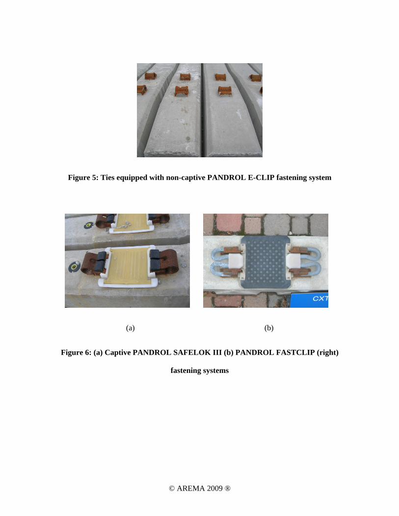
Figure 5: Ties equipped with non-captive PANDROL E-CLIP fastening system
(a) (b)
Figure 6: (a) Captive PANDROL SAFELOK III (b) PANDROL FASTCLIP (right)
fastening systems
© AREMA 2009 ®

Figure 7: Rail seat abrasion due to water intrusion [18]
© AREMA 2009 ®
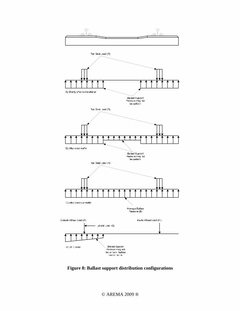
Figure 8: Ballast support distribution configurations
© AREMA 2009 ®

Figure 9: Estimated distribution of loads based on tie spacing [21]
© AREMA 2009 ®

(a) (b)
Figure 10: (a) View of entire indoor prestressing facility, 4 casting beds with rail system
situated in middle to transport ties out of facility, overhead gantry crane to service casting
beds (b) Form section consisting of 6 tie cells, 60 form sections makes up a single casting
bed, ties are cast upside down, forms are heated using circulating oil to control cure
temperature (pictures taken by author with permission of CXT)
© AREMA 2009 ®

(a) (b)
Figure 11: (a) Forms are cleaned to remove remaining concrete from previous batch and
coated with release agent to aid in de-molding (b) Ductile iron shoulder installed and
identification data installed prior to running of prestressing steel (pictures taken by author
with permission of CXT)
© AREMA 2009 ®
(a) (b)
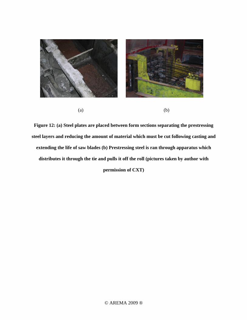
Figure 12: (a) Steel plates are placed between form sections separating the prestressing
steel layers and reducing the amount of material which must be cut following casting and
extending the life of saw blades (b) Prestressing steel is ran through apparatus which
distributes it through the tie and pulls it off the roll (pictures taken by author with
permission of CXT)
© AREMA 2009 ®
(a) (b)
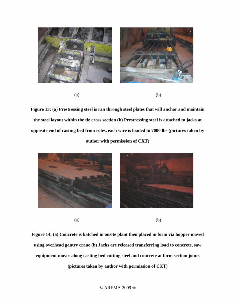
Figure 13: (a) Prestressing steel is ran through steel plates that will anchor and maintain
the steel layout within the tie cross section (b) Prestressing steel is attached to jacks at
opposite end of casting bed from roles, each wire is loaded to 7000 lbs (pictures taken by
author with permission of CXT)
(a) (b)
Figure 14: (a) Concrete is batched in onsite plant then placed in form via hopper moved
using overhead gantry crane (b) Jacks are released transferring load to concrete, saw
equipment moves along casting bed cutting steel and concrete at form section joints
(pictures taken by author with permission of CXT)
© AREMA 2009 ®
(a) (b)
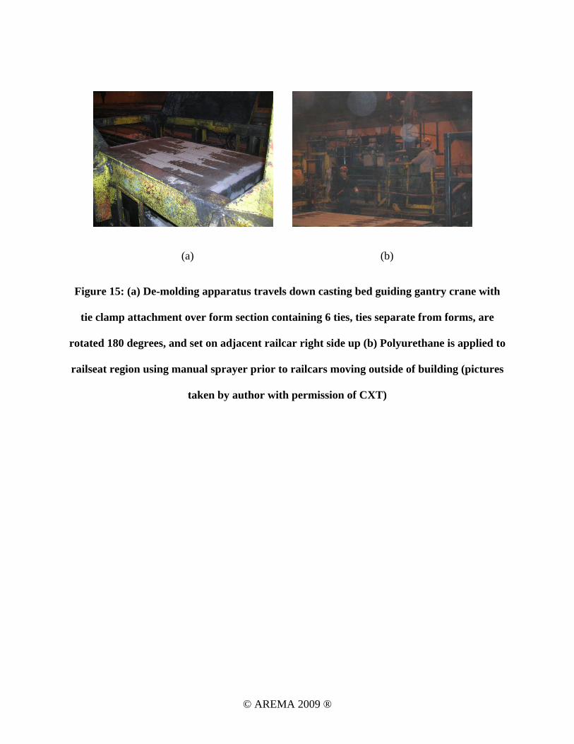
Figure 15: (a) De-molding apparatus travels down casting bed guiding gantry crane with
tie clamp attachment over form section containing 6 ties, ties separate from forms, are
rotated 180 degrees, and set on adjacent railcar right side up (b) Polyurethane is applied to
railseat region using manual sprayer prior to railcars moving outside of building (pictures
taken by author with permission of CXT)
© AREMA 2009 ®
TABLES & FIGURES
Figure 1: Generic concrete tie shape and dimensions
Figure 2: ACRL working alignment
Figure 3: (a) 7-wire prestressing strand, diameter 0.5 in. 270 ksi (b) prestressing wire,
diameter 0.21 in. 260 ksi
Figure 4: Embedded cast iron shoulder for PANDROL E-CLIP fastening system
Figure 5: Ties equipped with non-captive PANDROL E-CLIP fastening system
Figure 6: (a) Captive PANDROL SAFELOK III (b) PANDROL FASTCLIP (right)
fastening systems
Figure 7: Rail seat abrasion due to water intrusion [18]
Figure 8: Ballast support distribution configurations
Figure 9: Estimated distribution of loads based on tie spacing [21]
Figure 10: (a) View of entire indoor prestressing facility, 4 casting beds with rail system
situated in middle to transport ties out of facility, overhead gantry crane to service
casting beds (b) Form section consisting of 6 tie cells, 60 form sections makes up a
single casting bed, ties are cast upside down, forms are heated using circulating oil to
control cure temperature (pictures taken by author with permission of CXT)
Figure 11: (a) Forms are cleaned to remove remaining concrete from previous batch and
coated with release agent to aid in de-molding (b) Ductile iron shoulder installed and
identification data installed prior to running of prestressing steel (pictures taken by
author with permission of CXT)
Figure 12: (a) Steel plates are placed between form sections separating the prestressing
steel layers and reducing the amount of material which must be cut following casting
and extending the life of saw blades (b) Prestressing steel is ran through apparatus
© AREMA 2009 ®
which distributes it through the tie and pulls it off the roll (pictures taken by author
with permission of CXT)
Figure 13: (a) Prestressing steel is ran through steel plates that will anchor and maintain
the steel layout within the tie cross section (b) Prestressing steel is attached to jacks at
opposite end of casting bed from roles, each wire is loaded to 7000 lbs (pictures taken
by author with permission of CXT)
Figure 14: (a) Concrete is batched in onsite plant then placed in form via hopper moved
using overhead gantry crane (b) Jacks are released transferring load to concrete, saw
equipment moves along casting bed cutting steel and concrete at form section joints
(pictures taken by author with permission of CXT)
Figure 15: (a) De-molding apparatus travels down casting bed guiding gantry crane with
tie clamp attachment over form section containing 6 ties, ties separate from forms, are
rotated 180 degrees, and set on adjacent railcar right side up (b) Polyurethane is
applied to railseat region using manual sprayer prior to railcars moving outside of
building (pictures taken by author with permission of CXT)
© AREMA 2009 ®