Embed Size (px)
Citation preview
L U T 3L u m i n e s c e n c e S c a n n e r
TE
CH
NI
CA
LD
ES
CR
IP
TI
ON
2
Luminescence scanner
© · Industrial Sensors · Germany · All rights reserved · 8 007 920
Luminescence Scanners are used wherever standard scanners or contrast scanners do notensure reliable and unmistakable detection. Practical applications include e.g. monitoringadhesives, the grease in ball-bearings, control and positioning of labels etc.
The product can be marked with fluorescent chalk, ink, labels or the like. According to thekind of product, fluorescent markings can also be added. Thanks to the fact that most flu-orescent markings are invisible to the human eye, sorting, positioning and commissioningtasks or genuineness check can be solved easily.
A p p l i c a t i o n s
Long-life UV light 385 nm or 370 nm
No lamp replacement
Status and readiness indicator
Choice of scanning ranges through interchangeable objective lenses
Time delay adjustable (3, 5, 10, 20 ms, LUT 3-8 and LUT 3-9)
Insensitive to surface and mirror reflections
PNP and NPN output shortcircuit proof up to 100 mA
Two-position M 12 plug, 5-pin
Robust die-cast metal housing, IP 65
Analogue output (LUT 3-8 and LUT 3-9)
Supply voltage 12 to 30 V DC, reverse-polarity protected
High switching frequency
Short response time
Fibre-optic cable connection LUT 3-8 and LUT 3-9
Fe a t u re s
SICK Luminescence Scanners detect fluorescent materials or markings. They convert anoptical signal into a digital electrical signal. High-contrast markings, which stand out clearlyagainst the background, are reliably detected by photo-electrical sensors. The LUT 3 Lumi-nescence Scanner, however, detects fluorescent markings on any carrier material, regard-less of the pattern, colour or the kind of surface.
Ge n e r a l
A variety of fluorescent marking agents are commercially available, some of which are readyfor use. These substances owe their properties of fluorescence to added luminophors.These are small particles converting ultraviolet light of different wavelengths and intensityinto visible light. Luminophors can be added to almost any substance. Current fluorescentmarking agents include:
Daylight paints
Chalks and crayons
Labels
Fluorescent inks (including invisible ones)
Oils and greases
Felt-tip pens
A list of further fluorescent marking agents including sources of supply can be ordereddirectly from SICK: “Fluorescent Marking Agents”.
L u m i n o p h o r s
3
KT 5-2
8 007 920 · All rights reserved · Germany · Industrial Sensors · ©
LUT 3
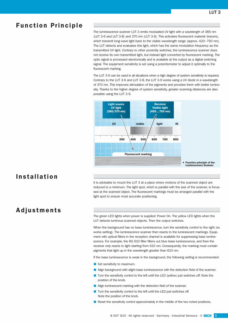
The luminescence scanner LUT 3 emits modulated UV light with a wavelength of 385 nm(LUT 3-6 and LUT 3-8) and 370 nm (LUT 3-9). This activates fluorescent material (tracers),which transmit long-wave light back to the visible wavelength range (approx. 420–750 nm).The LUT detects and evaluates this light, which has the same modulation frequency as thetransmitted UV light. Contrary to other proximity switches, the luminescence scanner doesnot receive its own transmitted light, but instead light converted by fluorescent marking. Theoptic signal is processed electronically and is available at the output as a digital switchingsignal. The equipment sensitivity is set using a potentiometer to adjust it optimally to the fluorescent marking.
The LUT 3-9 can be used in all situations when a high degree of system sensitivity is required.Contrary to the LUT 3-6 and LUT 3-8, the LUT 3-9 works using a UV diode in a wavelengthof 370 nm. This improves stimulation of the pigments and provides them with better lumino-sity. Thanks to the higher degree of system sensitivity, greater scanning distances are alsopossible using the LUT 3-9.
F u n c t i o n P r i n c i p l e
300
Light sourceUV light
(385/370 nm)
ReceiverVisible light
(450...750 nm)
IRvisibleUV light
400 500 600 700 800
Fluorescent marking
Function principle of theLuminescence Scanner
It is advisable to mount the LUT 3 at a place where motions of the scanned object arereduced to a minimum. The light spot, which is parallel with the axis of the scanner, is focus-sed at the scanned object. The fluorescent markings must be arranged parallel with thelight spot to ensure most accurate positioning.
I n s t a l l a t i o n
The green LED lights when power is supplied: Power On. The yellow LED lights when theLUT detects luminous scanned objects. Then the output switches.
When the background has no base luminescence, turn the sensitivity control to the right (exworks setting). The luminescence scanner then reacts to the luminescent markings. Equip-ment with optical filters in the reception channel is available for suppressing base lumine-scence. For example, the RG 610 filter filters out blue base luminescence, and then thereceiver only reacts to light starting from 610 nm. Consequently, the marking must containpigments that light up in the wavelength greater than 610 nm.
If the base luminescence is weak in the background, the following setting is recommended:
Set sensitivity to maximum.
Align background with slight base luminescence with the detection field of the scanner.
Turn the sensitivity control to the left until the LED (yellow) just switches off. Note theposition of the knob.
Align luminescent marking with the detection field of the scanner.
Turn the sensitivity control to the left until the LED just switches off. Note the position of the knob.
Reset the sensitivity control approximately in the middle of the two noted positions.
A d j u s t m e n t s
▲
4 © · Industrial Sensors · Germany · All rights reserved · 8 007 920
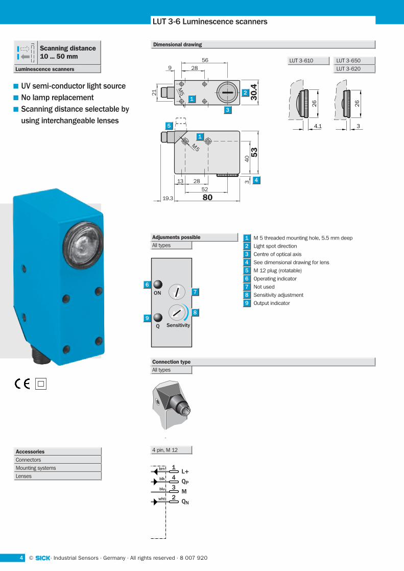
Lichtschranken Baureihe WL 27-2LUT 3-6 Luminescence scanners
UV semi-conductor light source
No lamp replacement
Scanning distance selectable by
using interchangeable lenses
M 5 threaded mounting hole, 5.5 mm deep
Light spot direction
Centre of optical axis
See dimensional drawing for lens
M 12 plug (rotatable)
Operating indicator
Not used
Sensitivity adjustment
Output indicator
1L+
QP
M
QN
4
3
2
brn
blk
blu
wht
8019.3
52
2813
40 5
33
0.4
21
3
28
569
5M
M5 2
3
1
1
5
4
8
9
Adjusments possible
All types
7
6
5
4
3
2
1
26
4.1 3
26
ON
Q Sensitivity
6
7
98
All types
Connection type
Dimensional drawing
LUT 3-610 LUT 3-650
LUT 3-620
4 pin, M 12
ON
Luminescence scanners
Scanning distance10 ... 50 mm
Accessories
Connectors
Mounting systems
Lenses
58 007 920 · All rights reserved · Germany · Industrial Sensors · ©
WL 27-2 LUT 3-6
610 620 650
1) From front edge of lens2) Average service life 100 ,000 h
at TA = + 25 °C
3) Limit values4) May not exceed or fall short of
VS tolerances
5) Without load6) Signal transit time with resistive load7) With light /dark ratio 1:18) Reference voltage 50 V DC
9) A = VS connections reverse-polarity protected
B = Outputs QP und QN short-circuit protected
C = Interference pulse suppression
(mm) 20 40 60 80 100
300
250
200
150
100
50
0Rela
tive
sens
itivi
ty in
%
1
2
3
Switching threshold
Scan material:
SICK Luminescence Scale 100 %
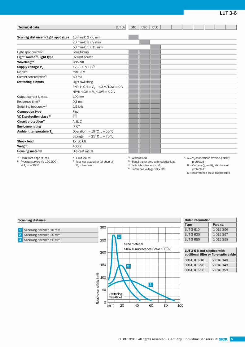
Scanning distance 10 mm
Scanning distance 20 mm
Scanning distance 50 mm3
2
1
Scanning distanceType
LUT 3-610
LUT 3-620
LUT 3-650
Part no.
1 015 396
1 015 397
1 015 398
Order information
LUT 3-6 is not sipplied with additional filter or fibre-optic cable
OBJ-LUT 3-10
OBJ-LUT 3-20
OBJ-LUT 3-50
2 016 348
2 016 349
2 016 350
Technical data LUT 3-
Scannig distance 1)/ light spot sizes 10 mm/Ø 2 x 6 mm
20 mm/Ø 3 x 9 mm
50 mm/Ø 5 x 15 mm
Light spot direction Longitudinal
Light source 2), light type UV light source
Wavelength 385 nm
Supply voltage VS 12 ... 30 V DC 3)
Ripple 4) max. 2 V
Current consumption5) 60 mA
Switching outputs Light-switching
PNP: HIGH = VS – <3 V/ LOW = 0 V
NPN: HIGH = VS / LOW = < 2 V
Output current IA max. 100 mA
Response time 6) 0.3 ms
Switching frequency 7) 1.5 kHz
Connection type Plug
VDE protection class 8)
Circuit protection 9) A, B, C
Enclosure rating IP 67
Ambient temperature TA Operation – 10 °C ... + 55 °C
Storage – 25 °C ... + 75 °C
Shock load To IEC 68
Weight 400 g
Housing material Die-cast metal
6 © · Industrial Sensors · Germany · All rights reserved · 8 007 920
Lichtschranken Baureihe WL 27-2
9
8
7
6
5
4
M 5 threaded mounting hole, 5.5 mm deep
Light spot direction
Centre of optical axis
See dimensional drawing for lens
M 12 plug (rotatable)
Operating indicator
Time delay selector switch
Sensitivity adjustment
Output indicator
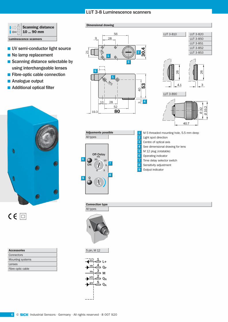
LUT 3-8 Luminescence scanners
UV semi-conductor light source
No lamp replacement
Scanning distance selectable by
using interchangeable lenses
Fibre-optic cable connection
Analogue output
Additional optical filter
1L+
QP
M
QN
QA
4
3
2
5
brn
blk
blu
wht
gra
8019.3
52
2813
40 5
33
0.4
21
3
28
569
5M
M5 2
3
1
1
5
4
Dimensional drawing
Adjusments possible
All types
3
2
1
26
4.1
Ø 3
3.2
Ø 3
2
40.7
3
26
LUT 3-890
ON
Q
Off-Delayms
20 10
5
30
6
7
98
All types
Connection type
LUT 3-810 LUT 3-820
LUT 3-850
LUT 3-851
LUT 3-852
LUT 3-853
Accessories
Connectors
Mounting systems
Lenses
Fibre-optic cable
ON
5 pin, M 12
Luminescence scanners
Scanning distance10 ... 90 mm
78 007 920 · All rights reserved · Germany · Industrial Sensors · ©
WL 27-2 LUT 3-8
810 820 850 890 851 852 853
1) From front edge of lens2) Average service life 100 ,000 h
at TA = + 25 °C
3) Limit values4) May not exceed or fall short of
VS tolerances
5) Without load6) Signal transit time with resistive load7) With light /dark ratio 1:18) Reference voltage 50 V DC
9) A = VS connections reverse-polarity protected
B = Outputs QP und QN short-circuit protected
C = Interference pulse suppression
(mm) 20 40 60 80 100
300
250
200
150
100
50
0Rela
tive
sens
itivi
ty in
%
1
2
3
Switching threshold
Scan material:
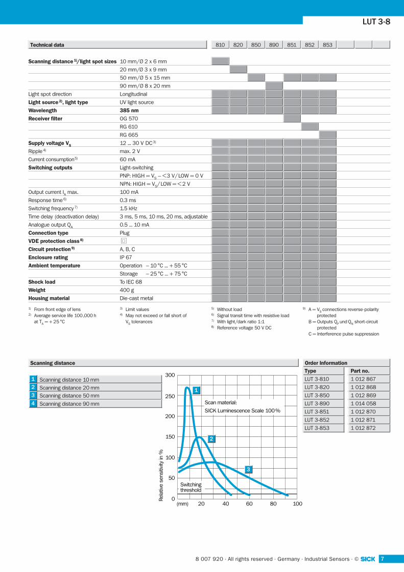
SICK Luminescence Scale 100 %Scanning distance 90 mm
Scanning distance 50 mmScanning distance 20 mm
Scanning distance 10 mm
4
3
2
1
Scanning distanceType
LUT 3-810
LUT 3-820
LUT 3-850
LUT 3-890
LUT 3-851
LUT 3-852
LUT 3-853
Part no.
1 012 867
1 012 868
1 012 869
1 014 058
1 012 870
1 012 871
1 012 872
Order Information
Technical data
Scanning distance 1)/light spot sizes 10 mm/Ø 2 x 6 mm
20 mm/Ø 3 x 9 mm
50 mm/Ø 5 x 15 mm
90 mm/Ø 8 x 20 mm
Light spot direction Longitudinal
Light source 2), light type UV light source
Wavelength 385 nm
Receiver filter OG 570
RG 610
RG 665
Supply voltage VS 12 ... 30 V DC 3)
Ripple 4) max. 2 V
Current consumption5) 60 mA
Switching outputs Light-switching
PNP: HIGH = VS – <3 V/ LOW = 0 V
NPN: HIGH = VS / LOW = < 2 V
Output current IA max. 100 mA
Response time 6) 0.3 ms
Switching frequency 7) 1.5 kHz
Time delay (deactivation delay) 3 ms, 5 ms, 10 ms, 20 ms, adjustable
Analogue output QA 0.5 ... 10 mA
Connection type Plug
VDE protection class 8)
Circuit protection 9) A, B, C
Enclosure rating IP 67
Ambient temperature Operation – 10 °C ... + 55 °C
Storage – 25 °C ... + 75 °C
Shock load To IEC 68
Weight 400 g
Housing material Die-cast metal
8 © · Industrial Sensors · Germany · All rights reserved · 8 007 920
Lichtschranken Baureihe WL 27-2
9
8
7
6
5
4
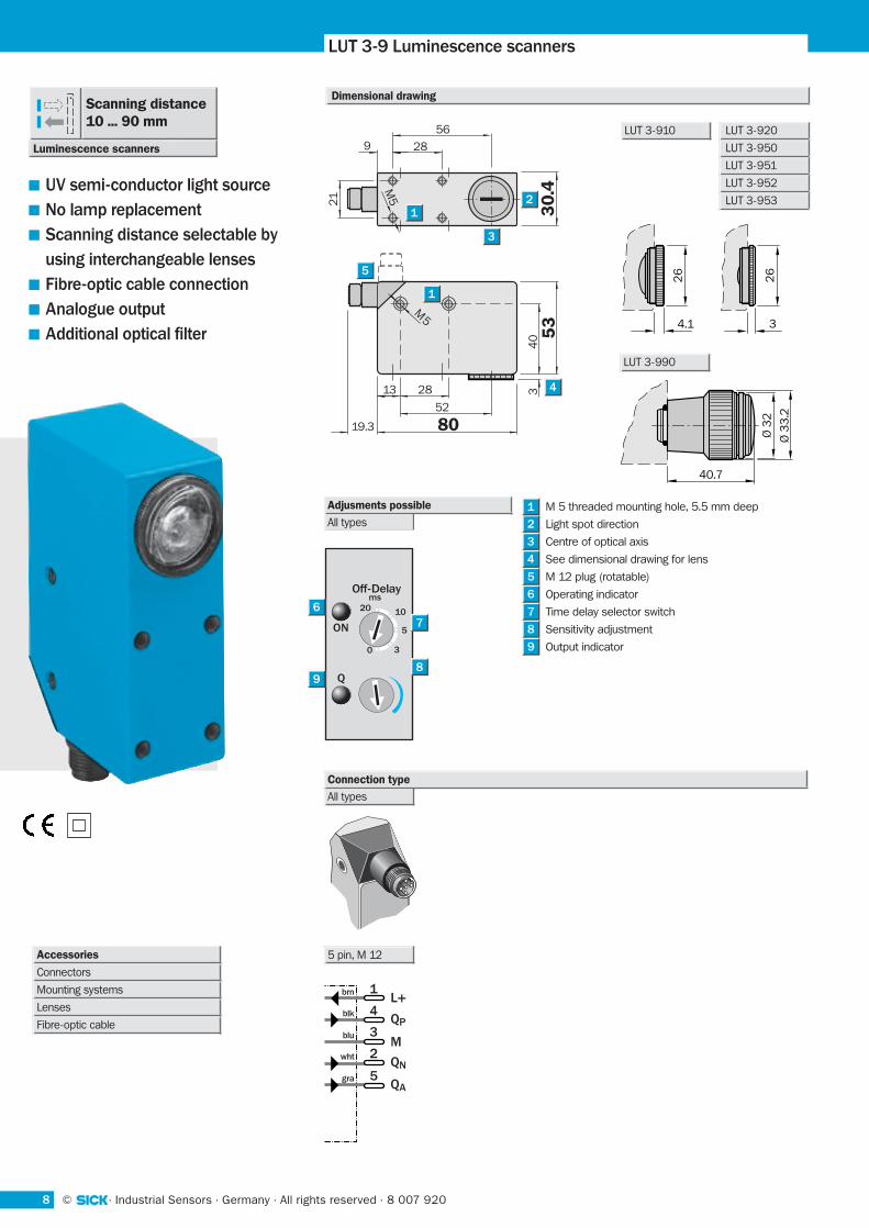
M 5 threaded mounting hole, 5.5 mm deep
Light spot direction
Centre of optical axis
See dimensional drawing for lens
M 12 plug (rotatable)
Operating indicator
Time delay selector switch
Sensitivity adjustment
Output indicator
LUT 3-9 Luminescence scanners
UV semi-conductor light source
No lamp replacement
Scanning distance selectable by
using interchangeable lenses
Fibre-optic cable connection
Analogue output
Additional optical filter
1L+
QP
M
QN
QA
4
3
2
5
brn
blk
blu
wht
gra
8019.3
52
2813
40 5
33
0.4
21
3
28
569
5M
M5 2
3
1
1
5
4
Dimensional drawing
Adjusments possible
All types
3
2
1
26
4.1 3
26
ON
Q
Off-Delayms
20 10
5
30
6
7
98
All types
Connection type
LUT 3-910 LUT 3-920
LUT 3-950
LUT 3-951
LUT 3-952
LUT 3-953
ON
5 pin, M 12
Luminescence scanners
Scanning distance10 ... 90 mm
Ø 3
3.2
Ø 3
2
40.7
LUT 3-990
Accessories
Connectors
Mounting systems
Lenses
Fibre-optic cable
98 007 920 · All rights reserved · Germany · Industrial Sensors · ©
WL 27-2 LUT 3-9
910 920 950 990 951 952 953
1) From front edge of lens2) Average service life 100 ,000 h
at TA = + 25 °C
3) Limit values4) May not exceed or fall short of
VS tolerances
5) Without load6) Signal transit time with resistive load7) With light /dark ratio 1:18) Reference voltage 50 V DC
9) A = VS connections reverse-polarity protected
B = Outputs QP und QN short-circuit protected
C = Interference pulse suppression
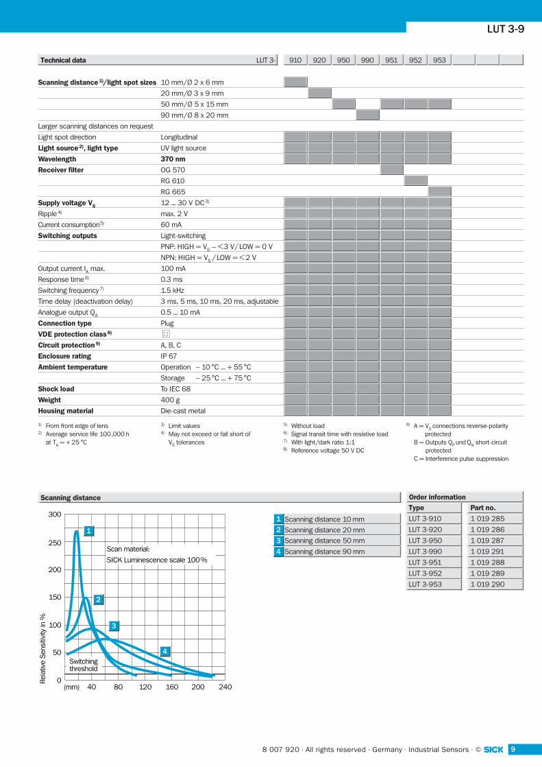
(mm) 40 80 120 160 200 240
300
250
200
150
100
50
0Rela
tive
Sens
itivi
ty in
%
1
2
3
Switching threshold
4
Scan material:
SICK Luminescence scale 100 %Scanning distance 90 mm
Scanning distance 50 mmScanning distance 20 mm
Scanning distance 10 mm1
2
3
4
Scanning distanceType
LUT 3-910
LUT 3-920
LUT 3-950
LUT 3-990
LUT 3-951
LUT 3-952
LUT 3-953
Part no.
1 019 285
1 019 286
1 019 287
1 019 291
1 019 288
1 019 289
1 019 290
Order information
Technical data LUT 3-
Scanning distance 1)/light spot sizes 10 mm/Ø 2 x 6 mm
20 mm/Ø 3 x 9 mm
50 mm/Ø 5 x 15 mm
90 mm/Ø 8 x 20 mm
Larger scanning distances on request
Light spot direction Longitudinal
Light source 2), light type UV light source
Wavelength 370 nm
Receiver filter OG 570
RG 610
RG 665
Supply voltage VS 12 ... 30 V DC 3)
Ripple 4) max. 2 V
Current consumption5) 60 mA
Switching outputs Light-switching
PNP: HIGH = VS – <3 V/ LOW = 0 V
NPN: HIGH = VS / LOW = < 2 V
Output current IA max. 100 mA
Response time 6) 0.3 ms
Switching frequency 7) 1.5 kHz
Time delay (deactivation delay) 3 ms, 5 ms, 10 ms, 20 ms, adjustable
Analogue output QA 0.5 ... 10 mA
Connection type Plug
VDE protection class 8)
Circuit protection 9) A, B, C
Enclosure rating IP 67
Ambient temperature Operation – 10 °C ... + 55 °C
Storage – 25 °C ... + 75 °C
Shock load To IEC 68
Weight 400 g
Housing material Die-cast metal
10 © · Industrial Sensors · Germany · All rights reserved · 8 007 920
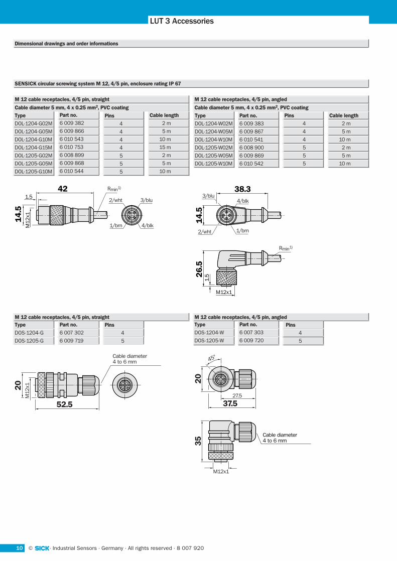
LUT 3 Accessories
Dimensional drawings and order informations
20
52.5
M12
x1
Cable diameter4 to 6 mm
37.5
M12x1
27.5
20
35
45°
Cable diameter4 to 6 mm
M 12 cable receptacles, 4/5 pin, straightType
DOS-1204-G
DOS-1205-G
M 12 cable receptacles, 4/5 pin, angledPins
4
5
Part no.
6 007 302
6 009 719
Pins
4
5
Type
DOS-1204-W
DOS-1205-W
Part no.
6 007 303
6 009 720
1.5
M12
x1
14
.5
42 Rmin1)
1/brn
2/wht 3/blu
4/blk
38.3
M12x1
26
.51
4.5
1.5
Rmin1)
4/blk
1/brn
3/blu
2/wht
M 12 cable receptacles, 4/5 pin, straight M 12 cable receptacles, 4/5 pin, angled
Cable diameter 5 mm, 4 x 0.25 mm2, PVC coating Cable diameter 5 mm, 4 x 0.25 mm2, PVC coating
Type
DOL-1204-G02M
DOL-1204-G05M
DOL-1204-G10M
DOL-1204-G15M
DOL-1205-G02M
DOL-1205-G05M
DOL-1205-G10M
Part no.
6 009 382
6 009 866
6 010 543
6 010 753
6 008 899
6 009 868
6 010 544
Pins
4
4
4
4
5
5
5
Cable length
2 m
5 m
10 m
15 m
2 m
5 m
10 m
Type
DOL-1204-W02M
DOL-1204-W05M
DOL-1204-W10M
DOL-1205-W02M
DOL-1205-W05M
DOL-1205-W10M
Part no.
6 009 383
6 009 867
6 010 541
6 008 900
6 009 869
6 010 542
SENSICK circular screwing system M 12, 4/5 pin, enclosure rating IP 67
Cable length
2 m
5 m
10 m
2 m
5 m
10 m
Pins
4
4
4
5
5
5
118 007 920 · All rights reserved · Germany · Industrial Sensors · ©
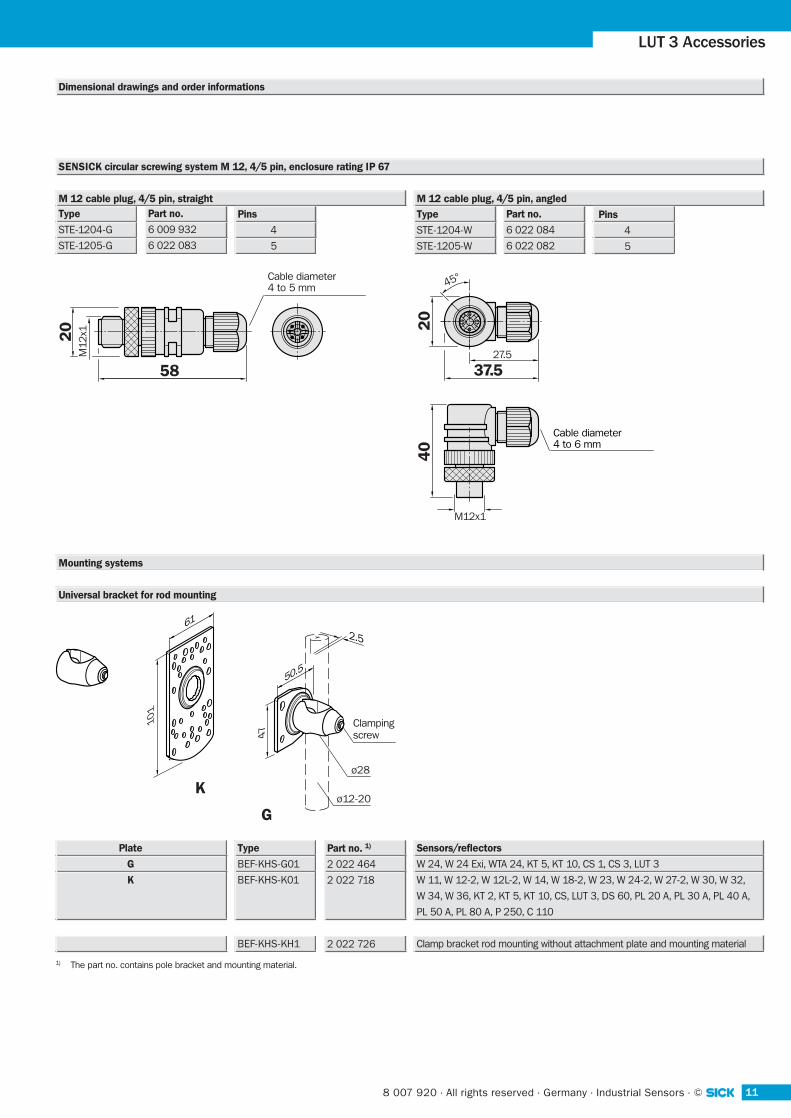
LUT 3 Accessories
SENSICK circular screwing system M 12, 4/5 pin, enclosure rating IP 67
20
58
M12
x1
Cable diameter4 to 5 mm
37.5
M12x1
27.5
20
40
45°
Cable diameter4 to 6 mm
M 12 cable plug, 4/5 pin, straightType
STE-1204-G
STE-1205-G
M 12 cable plug, 4/5 pin, angledPins
4
5
Part no.
6 009 932
6 022 083
Pins
4
5
Type
STE-1204-W
STE-1205-W
Part no.
6 022 084
6 022 082
Dimensional drawings and order informations
Universal bracket for rod mounting
Type
BEF-KHS-G01
BEF-KHS-K01
BEF-KHS-KH1
Part no. 1)
2 022 464
2 022 718
2 022 726
Sensors/reflectors
W 24, W 24 Exi, WTA 24, KT 5, KT 10, CS 1, CS 3, LUT 3
W 11, W 12-2, W 12L-2, W 14, W 18-2, W 23, W 24-2, W 27-2, W 30, W 32,
W 34, W 36, KT 2, KT 5, KT 10, CS, LUT 3, DS 60, PL 20 A, PL 30 A, PL 40 A,
PL 50 A, PL 80 A, P 250, C 110
Clamp bracket rod mounting without attachment plate and mounting material
Plate
G
K
1) The part no. contains pole bracket and mounting material.
G
2.5
ø12-20
ø28
Clampingscrew
K
101
61
47
50.5
Mounting systems
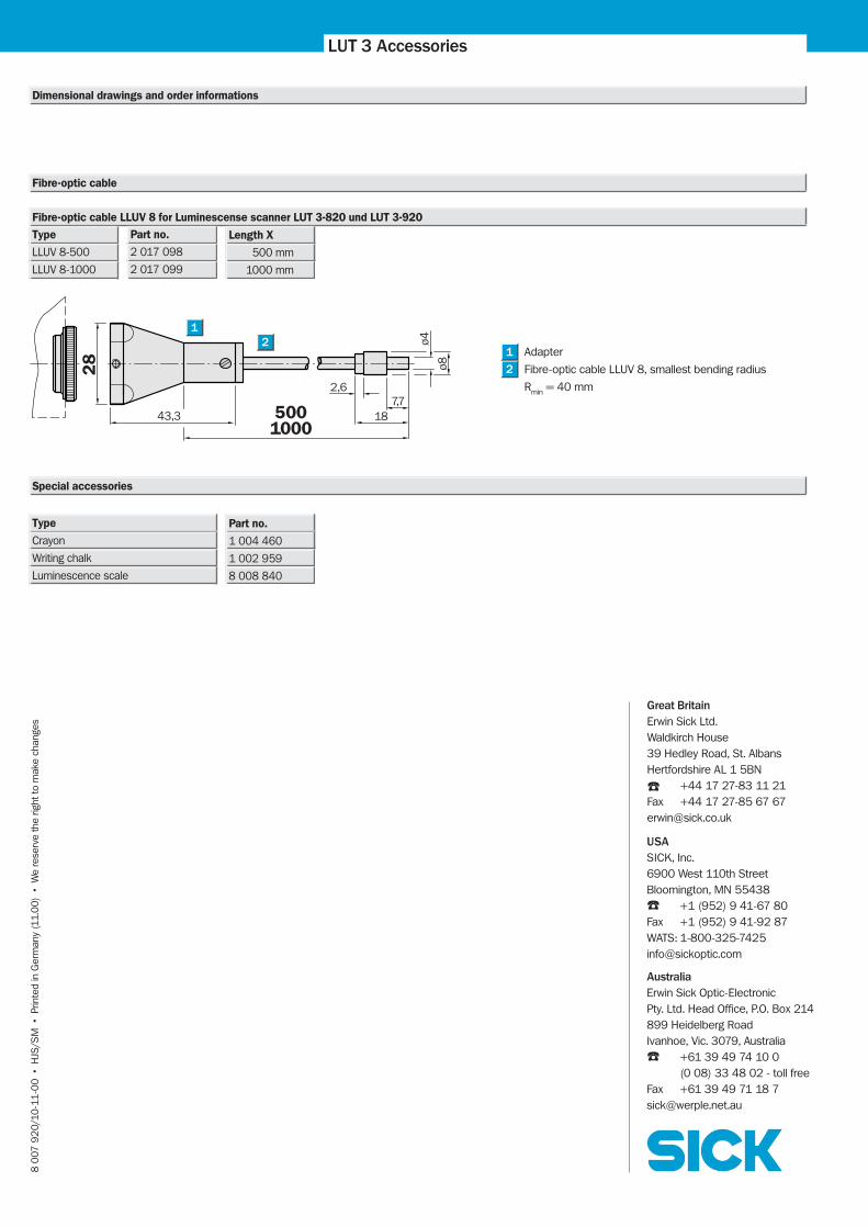
LUT 3 Accessories
Fibre-optic cable LLUV 8 for Luminescense scanner LUT 3-820 und LUT 3-920
Type
LLUV 8-500
LLUV 8-1000
Length X
500 mm
1000 mm
Part no.
2 017 098
2 017 099
Adapter
Fibre-optic cable LLUV 8, smallest bending radius
Rmin = 40 mm
2
1
Dimensional drawings and order informations
Fibre-optic cable
Special accessories
Type
Crayon
Writing chalk
Luminescence scale
28 ø8
ø443,3 500
1000
2,67,7
18
1
2
Part no.
1 004 460
1 002 959
8 008 840
8 0
07 9
20
/10
-11
-00
• H
JS/S
M •
Prin
ted
in G
erm
any
(11.
00
) •
We
rese
rve
the
right
to m
ake
chan
ges
Great Britain
Erwin Sick Ltd.Waldkirch House39 Hedley Road, St. AlbansHertfordshire AL 1 5BN
☎ +44 17 27-83 11 21Fax +44 17 27-85 67 [email protected]
USA
SICK, Inc.6900 West 110th StreetBloomington, MN 55438☎ +1 (952) 9 41-67 80Fax +1 (952) 9 41-92 87WATS: [email protected]
Australia
Erwin Sick Optic-ElectronicPty. Ltd. Head Office, P.O. Box 214899 Heidelberg RoadIvanhoe, Vic. 3079, Australia☎ +61 39 49 74 10 0
(0 08) 33 48 02 - toll freeFax +61 39 49 71 18 [email protected]