Embed Size (px)
Citation preview
Basis of Design,a case study building
Luís Simões da SilvaDepartment of Civil Engineering University of Coimbra
Eurocodes ‐ Design of steel buildings with worked examples Brussels, 16 ‐ 17 October 2014
Contents
Definitions and basis of design
Global analysis• Structural modeling
• Structural analysis
• Case study: building
Classification of cross‐sections
Eurocodes ‐ Design of steel buildings with worked examples Brussels, 16 ‐ 17 October 2014
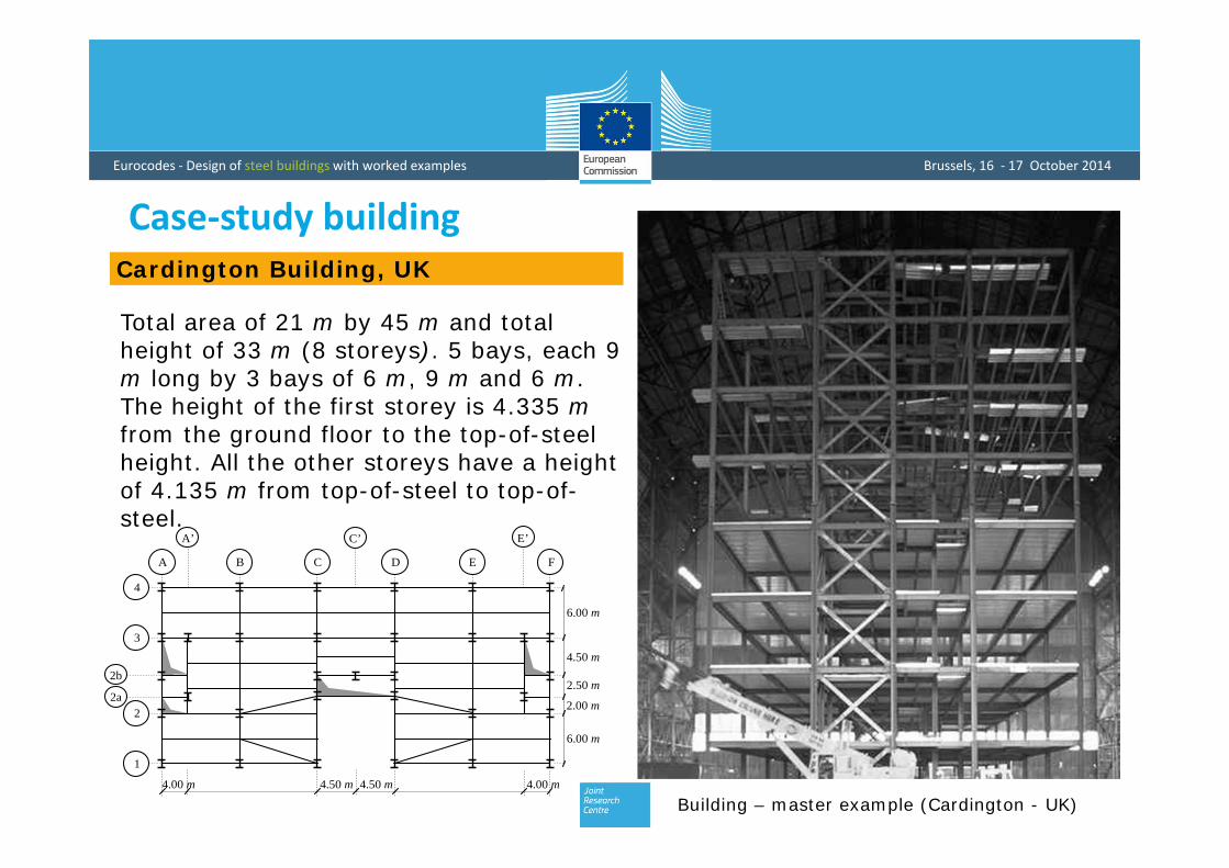
Building – master example (Cardington - UK)
Total area of 21 m by 45 m and total height of 33 m (8 storeys). 5 bays, each 9 m long by 3 bays of 6 m, 9 m and 6 m. The height of the first storey is 4.335 mfrom the ground floor to the top-of-steel height. All the other storeys have a height of 4.135 m from top-of-steel to top-of-steel.
Case‐study buildingCardington Building, UK
B A C D E F
1
2
3
4
4.00 m 4.50 m 4.50 m 4.00 m
2b
2a
A’ C’ E’
4.50 m
6.00 m
6.00 m
2.50 m
2.00 m

Eurocodes ‐ Design of steel buildings with worked examples Brussels, 16 ‐ 17 October 2014
Geometric Characteristics of Steel Members
Global Analysis: case‐study building
Geometric characteristics of the beams (1st floor)
Geometric characteristics of the columns
Geometric characteristics of the beams (3rd to 8th floors)
Geometric characteristics of the beams (2nd
floor)
Eurocodes ‐ Design of steel buildings with worked examples Brussels, 16 ‐ 17 October 2014
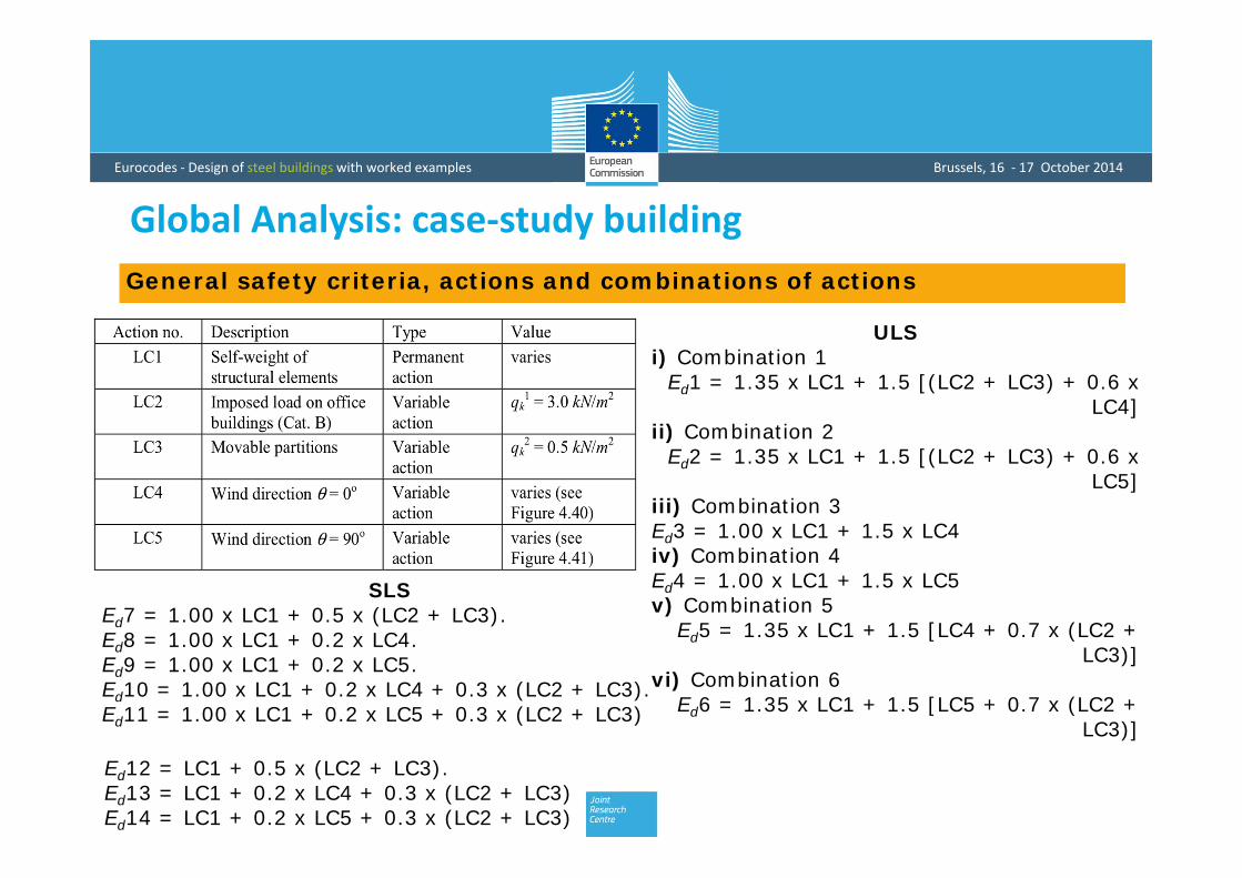
General safety criteria, actions and combinations of actions
Global Analysis: case‐study building
ULSi) Combination 1
Ed1 = 1.35 x LC1 + 1.5 [(LC2 + LC3) + 0.6 x LC4]
ii) Combination 2Ed2 = 1.35 x LC1 + 1.5 [(LC2 + LC3) + 0.6 x
LC5]iii) Combination 3Ed3 = 1.00 x LC1 + 1.5 x LC4iv) Combination 4Ed4 = 1.00 x LC1 + 1.5 x LC5v) Combination 5
Ed5 = 1.35 x LC1 + 1.5 [LC4 + 0.7 x (LC2 + LC3)]
vi) Combination 6Ed6 = 1.35 x LC1 + 1.5 [LC5 + 0.7 x (LC2 +
LC3)]
SLSEd7 = 1.00 x LC1 + 0.5 x (LC2 + LC3).Ed8 = 1.00 x LC1 + 0.2 x LC4.Ed9 = 1.00 x LC1 + 0.2 x LC5.Ed10 = 1.00 x LC1 + 0.2 x LC4 + 0.3 x (LC2 + LC3).Ed11 = 1.00 x LC1 + 0.2 x LC5 + 0.3 x (LC2 + LC3)
Ed12 = LC1 + 0.5 x (LC2 + LC3).Ed13 = LC1 + 0.2 x LC4 + 0.3 x (LC2 + LC3)Ed14 = LC1 + 0.2 x LC5 + 0.3 x (LC2 + LC3)

Eurocodes ‐ Design of steel buildings with worked examples Brussels, 16 ‐ 17 October 2014
Structural analysis
Global Analysis: case‐study building
Linear elastic analysis
Susceptibility to 2nd order effects: elastic critical loads
2nd order elastic analysisFor combinations 1, 2, 5 and 6 the values of crare smaller than 10. According to clause 5.2.1, the frame requires a second-order analysis for load combinations 1, 2, 5 and 6.
Eurocodes ‐ Design of steel buildings with worked examples Brussels, 16 ‐ 17 October 2014
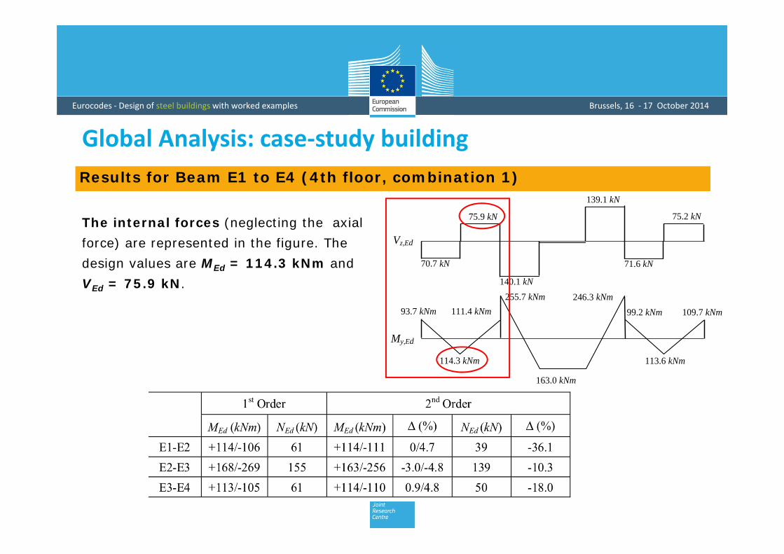
Results for Beam E1 to E4 (4th floor, combination 1)
The internal forces (neglecting the axial force) are represented in the figure. The design values are MEd = 114.3 kNm and VEd = 75.9 kN.
246.3 kNm
My,Ed
114.3 kNm
163.0 kNm
113.6 kNm
93.7 kNm 255.7 kNm
109.7 kNm 99.2 kNm 111.4 kNm
Vz,Ed
70.7 kN
75.9 kN
139.1 kN
75.2 kN
71.6 kN
140.1 kN
Global Analysis: case‐study building
Eurocodes ‐ Design of steel buildings with worked examples Brussels, 16 ‐ 17 October 2014
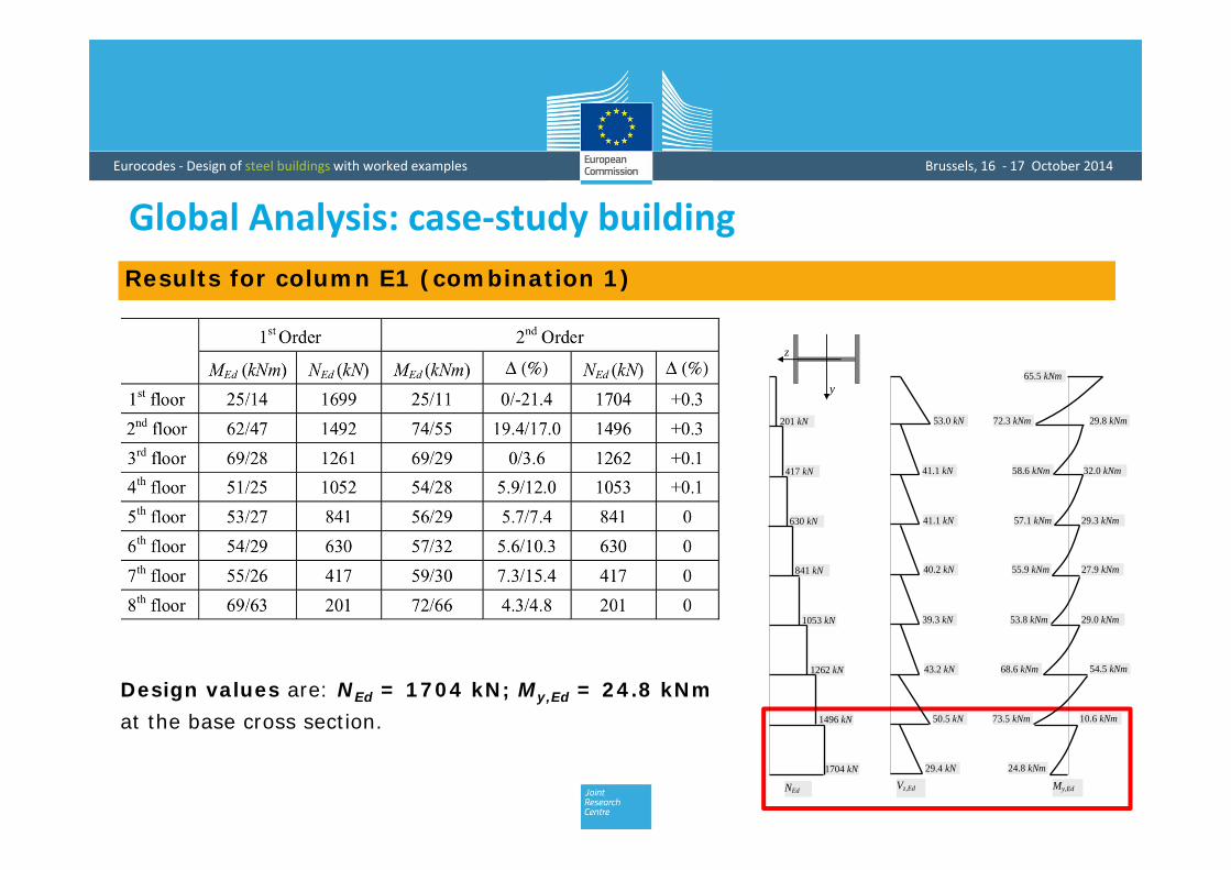
Results for column E1 (combination 1)
Design values are: NEd = 1704 kN; My,Ed = 24.8 kNmat the base cross section.
201 kN
1496 kN
1704 kN
1262 kN
1053 kN
841 kN
630 kN
417 kN
NEd
53.0 kN
50.5 kN
29.4 kN
43.2 kN
39.3 kN
40.2 kN
41.1 kN
41.1 kN
Vz,Ed My,Ed
29.8 kNm
10.6 kNm
54.5 kNm
29.0 kNm
27.9 kNm
29.3 kNm
32.0 kNm
72.3 kNm
73.5 kNm
68.6 kNm
53.8 kNm
55.9 kNm
57.1 kNm
58.6 kNm
24.8 kNm
65.5 kNmy
z
Global Analysis: case‐study building

Eurocodes ‐ Design of steel buildings with worked examples Brussels, 16 ‐ 17 October 2014
Mpl
Mel
M
s
Class 1 Class 2
Class 3
Class 4
Class 1: plastic cross-sections
Class 2: compact cross-sections
Class 3: semi-compact cross-sections
Class 4: slender cross-sections
Classification of cross‐sections

Eurocodes ‐ Design of steel buildings with worked examples Brussels, 16 ‐ 17 October 2014
MRd
Class 1 Class 3 Class 4Cla
ss 2
c/t
Mpl
Mel
Elastic global analysisPlastic global analysis
Mpl Mel Meff
discontinuity
Classification of cross‐sections
Semi-Comp, Guimarães 2011

Eurocodes ‐ Design of steel buildings with worked examples Brussels, 16 ‐ 17 October 2014
Classification of cross‐sectionsCross section classification is required for: Selection of the global frame analysis:
Elastic frame analysis
Plastic frame analysis
Decision about the type of cross-section verification:
Elastic verification
Plastic verification
Effective cross-section properties
Decision on the member buckling formulae with respect to the
degree of local plastic capacity:
Plastic interaction: class 1, 2
Elastic interaction

Eurocodes ‐ Design of steel buildings with worked examples Brussels, 16 ‐ 17 October 2014
Classification of cross‐sectionsHow to classify a cross‐section?
Classification of each plate elements (in full or partialcompression) composing the section.
Compare the slenderness c/t with specific limits, establishedto prevent local plate buckling (Table 5.2 of EC3-1-1).
Cross section class = most unfavourable class of all plate elements (flange or web).
Cross section class depend of the: slenderness c/t; support conditions (internal or external part); distribution of direct stresses (acting forces); class of steel (higher steel grades sections tend to fall into
higher classes).
bL
Free edge
Simple support
t

Eurocodes ‐ Design of steel buildings with worked examples Brussels, 16 ‐ 17 October 2014
Plate elementclassification
acc. to Table 5.2
235 / yf

Eurocodes ‐ Design of steel buildings with worked examples Brussels, 16 ‐ 17 October 2014
Plate element classification
acc. to Table 5.2

Eurocodes ‐ Design of steel buildings with worked examples Brussels, 16 ‐ 17 October 2014
Thank you for your attention
Acknowledgments
• Use of material (powerpoint presentations from SEMI-COMP+ Seminar in Guimarães, Portugal, 23.NOV.2011) is gratefully acknowledged.