Embed Size (px)
Citation preview
Sun City South Africa, May 4 - 6th , 2009
LURECLUREC®® Process Process
Sulphur Sulphur && Sulphuric Acid Sulphuric Acid 2009 2009 ConferenceConference
The Southern African Institute of Mining and Metallurgy&
South African Sulphuric Acid Producer‘s Society
ProcessingProcessing ofof
ConcentratedConcentrated SOSO22 GasGas
from from
Metallurgical OperationsMetallurgical Operations
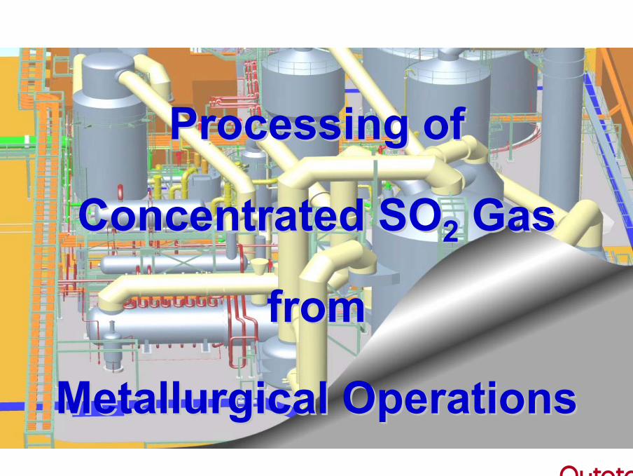
Challenges:• Strong gases (30 – 60 %-vol. SO2) from smelter processes available• High SO2 High Temperatures
Advantages of Processing Strong Gases• Smaller equipment → reduced investment cost• Lower gas flow → less energy demand• Higher SO2-content → higher energy recovery potential
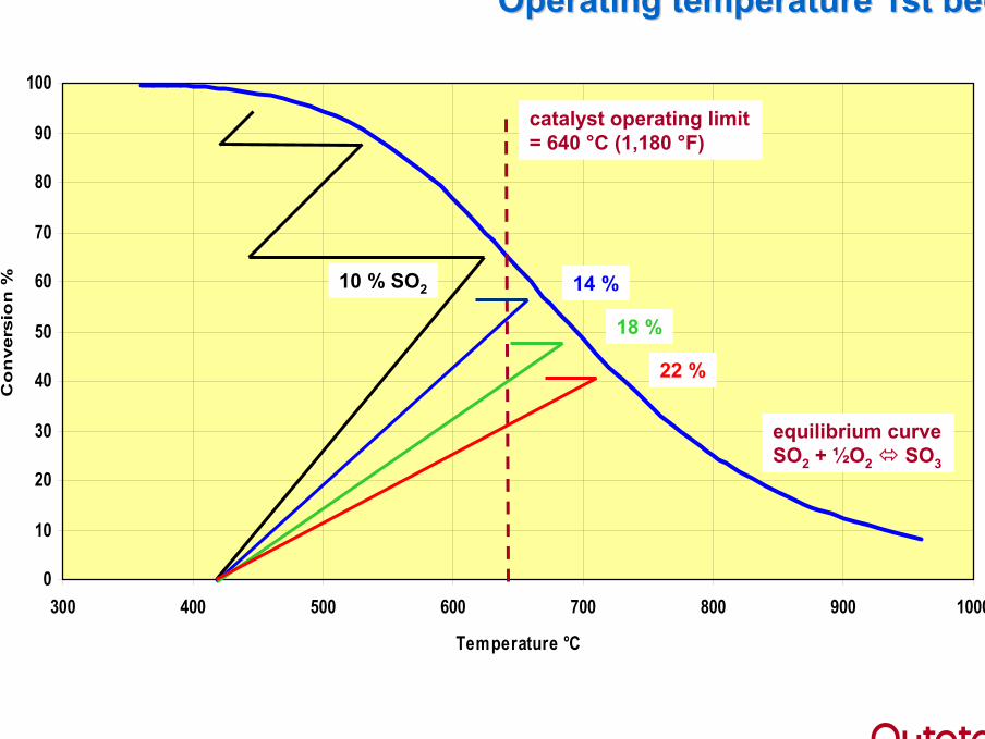
Limitations• Thermostability of catalyst (approx. 640 °C)
Solutions• Trivial solution, -dilute the gas with air to 12…13%-vol. SO2• Other, more sophisticated solutions
ProcessingProcessing ofof StrongStrong GasGas
0
10
20
30
40
50
60
70
80
90
100
300 400 500 600 700 800 900 1000
Temperature °C
Co
nve
rsio
n %
Operating temperatureOperating temperature 1st1st bedbed
10 % SO2
catalyst operating limit= 640 °C (1,180 °F)
14 %
18 %
22 %
equilibrium curveSO2 + ½O2 SO3
Concepts Concepts & & HistoryHistory
Strong Strong SOSO22 GasGas
ProcessingProcessing
1. Dual 1. Dual FlowFlow
ConceptConcept
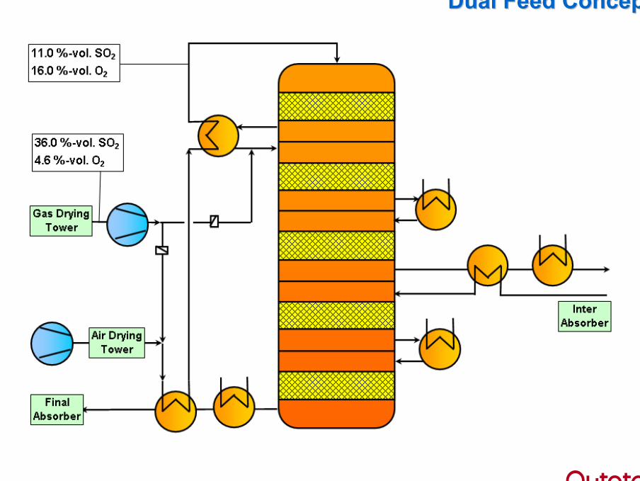
DualDual Feed ConceptFeed Concept
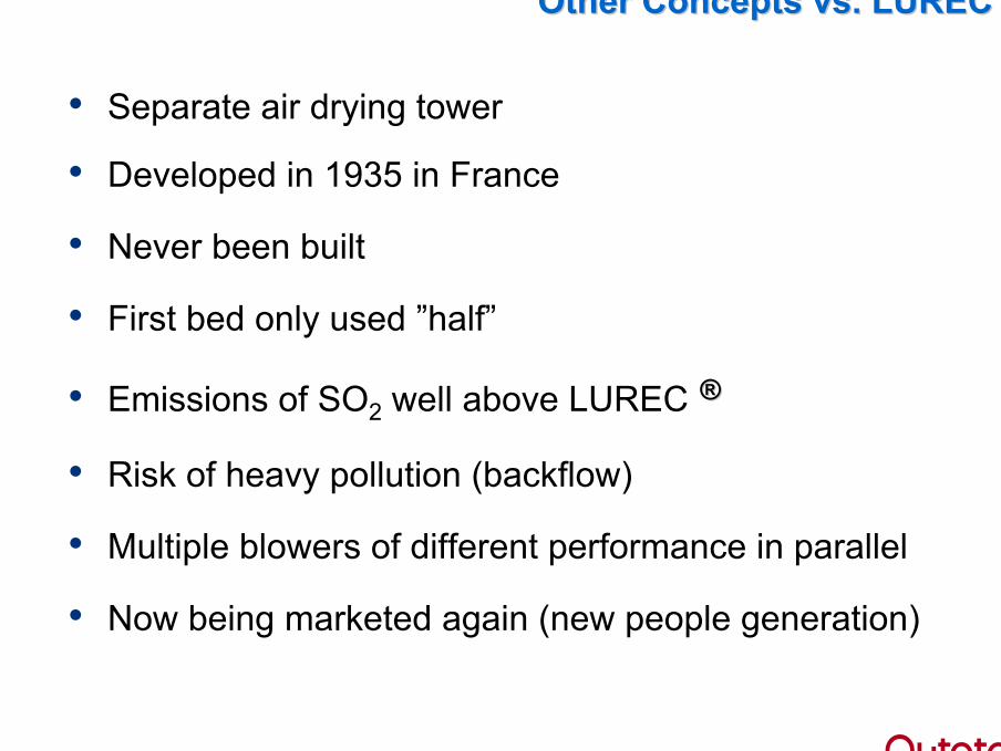
• Separate air drying tower
• Developed in 1935 in France
• Never been built
• First bed only used ”half”
• Emissions of SO2 well above LUREC ®®
• Risk of heavy pollution (backflow)
• Multiple blowers of different performance in parallel
• Now being marketed again (new people generation)
Other ConceptsOther Concepts vs. LURECvs. LUREC ®®

2. 2. Fluidized BedFluidized Bed
ConceptConcept
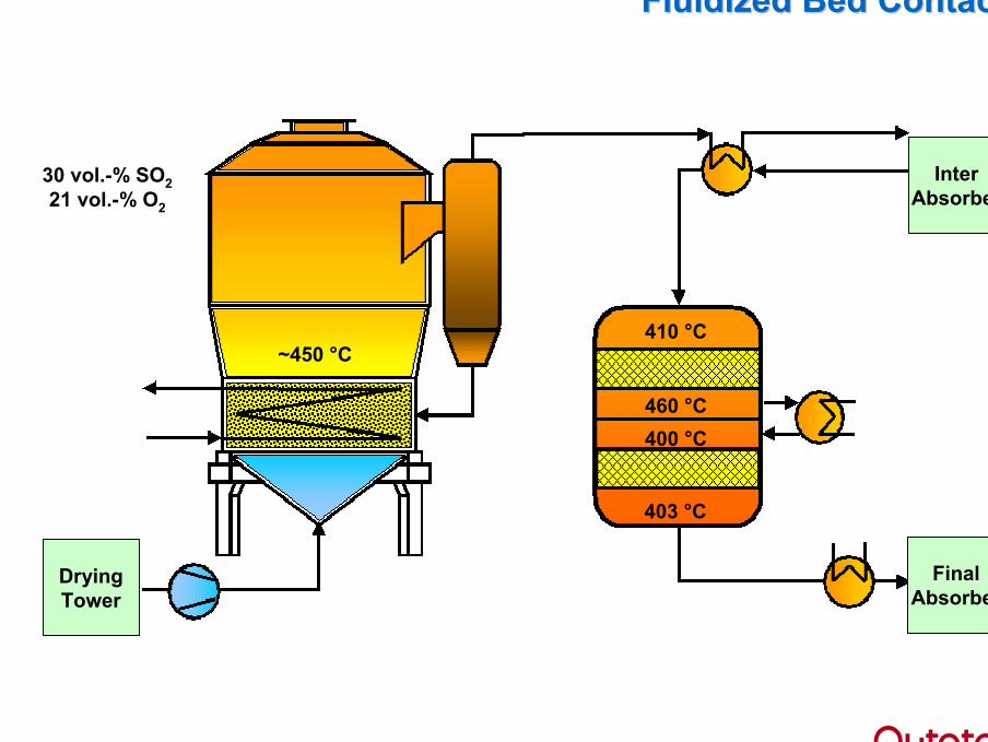
410 °C
460 °C400 °C
403 °C
~450 °C
Fluidized Bed ContactFluidized Bed Contact
30 vol.-% SO221 vol.-% O2
DryingTower
InterAbsorber
FinalAbsorber
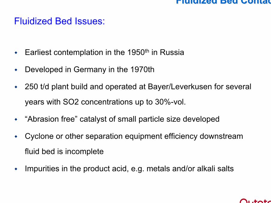
Fluidized Bed Issues:
Earliest contemplation in the 1950th in Russia
Developed in Germany in the 1970th
250 t/d plant build and operated at Bayer/Leverkusen for several
years with SO2 concentrations up to 30%-vol.
“Abrasion free” catalyst of small particle size developed
Cyclone or other separation equipment efficiency downstream
fluid bed is incomplete
Impurities in the product acid, e.g. metals and/or alkali salts
Fluidized Bed ContactFluidized Bed Contact

3. 3. IsothermalIsothermal
ConceptConcept
InterAbsorber
FinalAbsorber
DryingTower
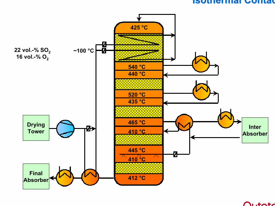
540 °C440 °C
520 °C435 °C
465 °C410 °C
425 °C
445 °C410 °C
412 °C
~100 °C
Isothermal ContactIsothermal Contact
22 vol.-% SO216 vol.-% O2
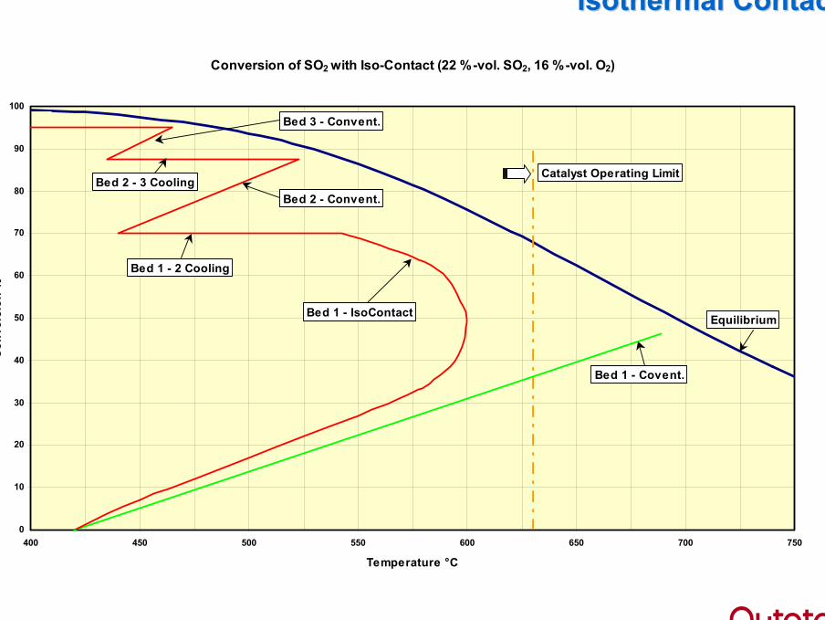
Conversion of SO2 with Iso-Contact (22 %-vol. SO2, 16 %-vol. O2)
0
10
20
30
40
50
60
70
80
90
100
400 450 500 550 600 650 700 750
Temperature °C
Con
vers
ion
%
Bed 1 - IsoContact
Bed 2 - Convent.
Bed 1 - Covent.
Equilibrium
Bed 1 - 2 Cooling
Catalyst Operating LimitBed 2 - 3 Cooling
Bed 3 - Convent.
Isothermal ContactIsothermal Contact
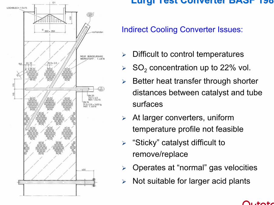
LurgiLurgi TestTest ConverterConverter BASF 1985BASF 1985
Indirect Cooling Converter Issues:
Difficult to control temperatures
SO2 concentration up to 22% vol.
Better heat transfer through shorter distances between catalyst and tube surfaces
At larger converters, uniform temperature profile not feasible
“Sticky” catalyst difficult to remove/replace
Operates at “normal” gas velocities
Not suitable for larger acid plants
4. Tube 4. Tube ReactorReactor
ConceptConcept
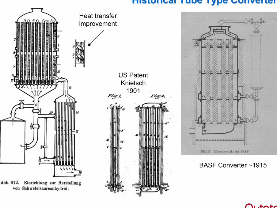
HistoricalHistorical Tube TypeTube Type ConvertersConvertersHeat transferimprovement
US PatentKnietsch
1901
BASF Converter ~1915
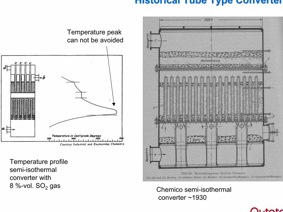
HistoricalHistorical Tube TypeTube Type ConvertersConverters
Chemico semi-isothermalconverter ~1930
Temperature profilesemi-isothermalconverter with 8 %-vol. SO2 gas
Temperature peakcan not be avoided
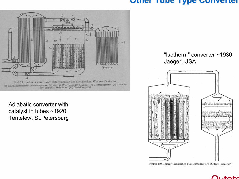
OtherOther Tube TypeTube Type ConvertersConverters
Adiabatic converter with catalyst in tubes ~1920Tentelew, St.Petersburg
“Isotherm” converter ~1930Jaeger, USA
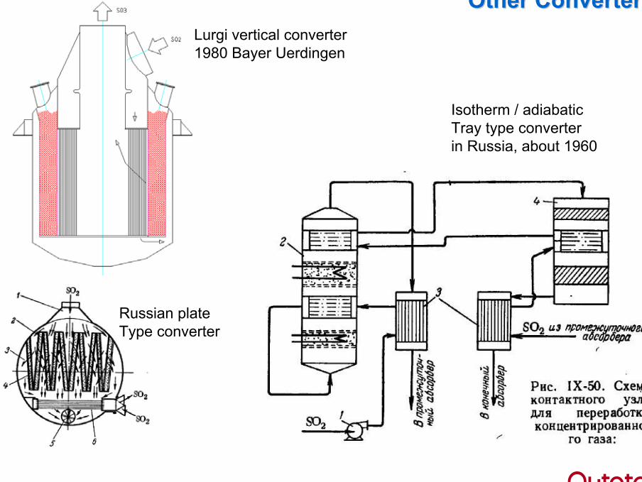
Other ConvertersOther ConvertersLurgi vertical converter1980 Bayer Uerdingen
Isotherm / adiabaticTray type converterin Russia, about 1960
Russian plateType converter
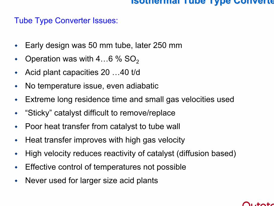
Tube Type Converter Issues:
Early design was 50 mm tube, later 250 mm
Operation was with 4…6 % SO2
Acid plant capacities 20 …40 t/d
No temperature issue, even adiabatic
Extreme long residence time and small gas velocities used
“Sticky” catalyst difficult to remove/replace
Poor heat transfer from catalyst to tube wall
Heat transfer improves with high gas velocity
High velocity reduces reactivity of catalyst (diffusion based)
Effective control of temperatures not possible
Never used for larger size acid plants
IsothermalIsothermal Tube TypeTube Type ConverterConverter

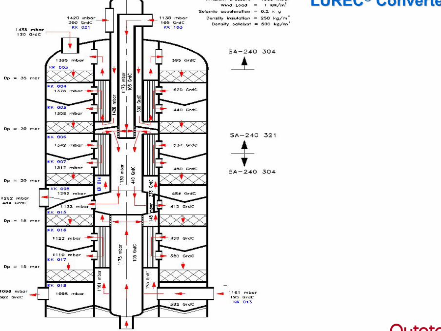
5. LUREC5. LUREC®®
ConceptConcept
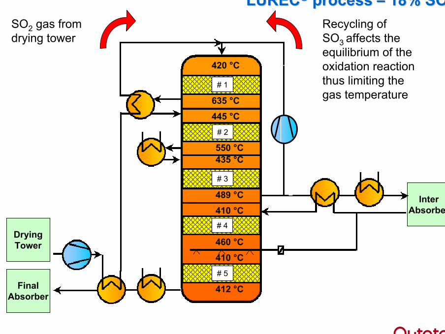
LURECLUREC®® processprocess –– 18% SO18% SO22
InterAbsorber
FinalAbsorber
DryingTower
435 °C550 °C
445 °C635 °C
420 °C
460 °C
410 °C489 °C
410 °C
412 °C
# 1
# 2
# 3
# 4
# 5
Recycling ofSO3 affects theequilibrium of theoxidation reactionthus limiting thegas temperature
SO2 gas fromdrying tower
LURECLUREC®® processprocess
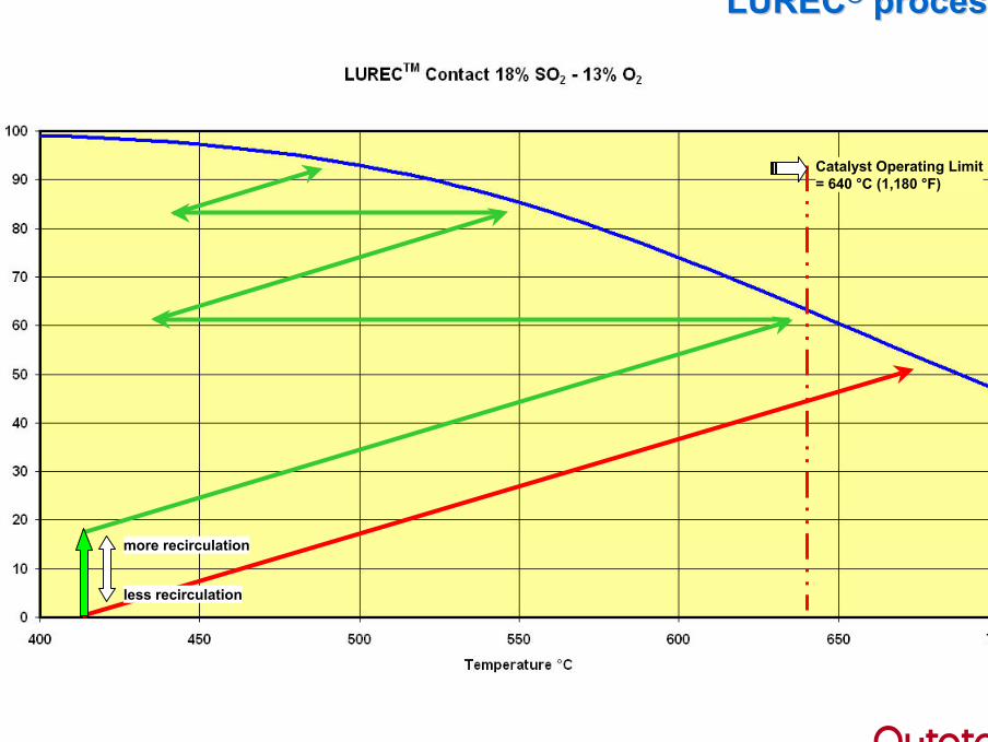
Catalyst Operating Limit= 640 °C (1,180 °F)
more recirculation
less recirculation
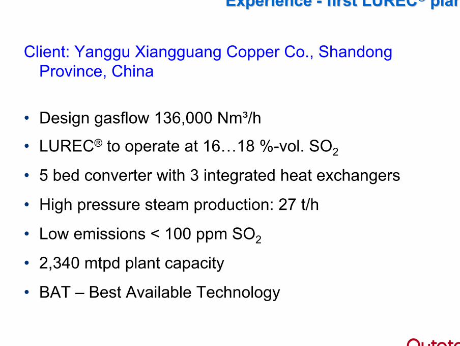
Client: Yanggu Xiangguang Copper Co., ShandongProvince, China
• Design gasflow 136,000 Nm³/h
• LUREC® to operate at 16…18 %-vol. SO2
• 5 bed converter with 3 integrated heat exchangers
• High pressure steam production: 27 t/h
• Low emissions < 100 ppm SO2
• 2,340 mtpd plant capacity
• BAT – Best Available Technology
ExperienceExperience -- firstfirst LURECLUREC®® plantplant
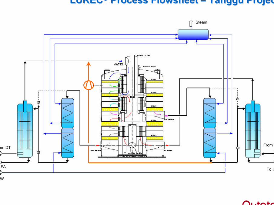
LURECLUREC®® Process FlowsheetProcess Flowsheet –– Yanggu ProjectYanggu Project
From DT
To FA
BFW
From IA
To IA
Steam
LURECLUREC®® ConverterConverter
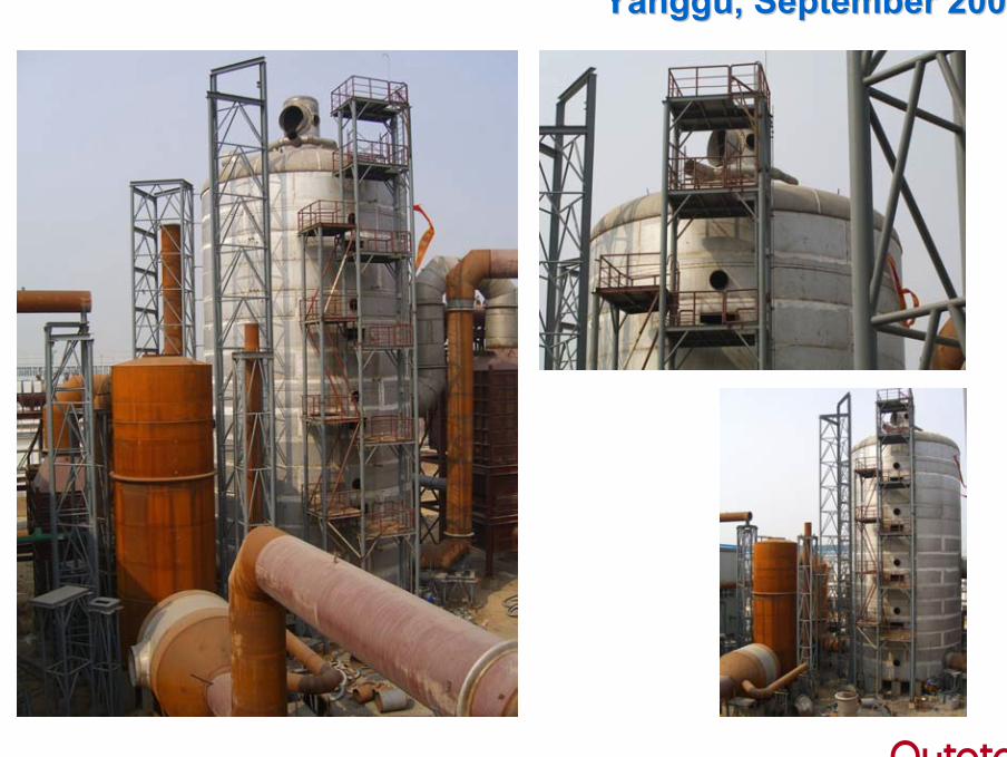
YangguYanggu, September 2006, September 2006
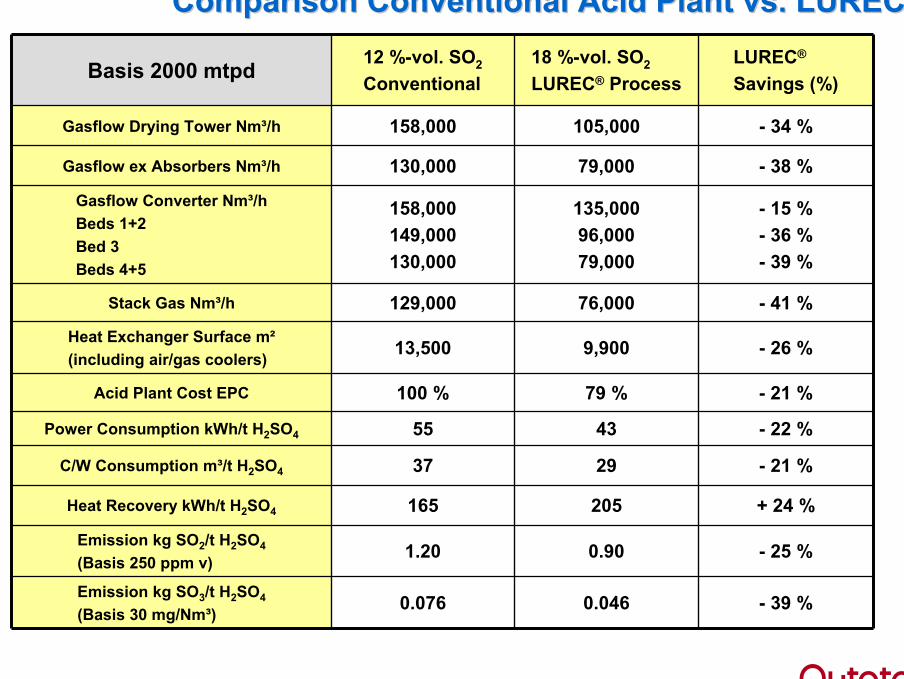
Basis 2000 mtpd 12 %-vol. SO2
Conventional18 %-vol. SO2
LUREC® ProcessLUREC®
Savings (%)
Gasflow Drying Tower Nm³/h 158,000 105,000 - 34 %
Gasflow ex Absorbers Nm³/h 130,000 79,000 - 38 %
Gasflow Converter Nm³/hBeds 1+2Bed 3Beds 4+5
158,000149,000130,000
135,00096,00079,000
- 15 %- 36 %- 39 %
Stack Gas Nm³/h 129,000 76,000 - 41 %
Heat Exchanger Surface m²(including air/gas coolers) 13,500 9,900 - 26 %
Acid Plant Cost EPC 100 % 79 % - 21 %
Power Consumption kWh/t H2SO4 55 43 - 22 %
C/W Consumption m³/t H2SO4 37 29 - 21 %
Heat Recovery kWh/t H2SO4 165 205 + 24 %
Emission kg SO2/t H2SO4
(Basis 250 ppm v) 1.20 0.90 - 25 %
Emission kg SO3/t H2SO4
(Basis 30 mg/Nm³) 0.076 0.046 - 39 %
Comparison Conventional AcidComparison Conventional Acid Plant vs. Plant vs. LURECLUREC®®
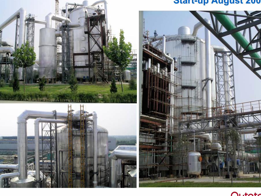
StartStart--up August 2007up August 2007
ConverterConverter DesignDesign
FeaturesFeatures
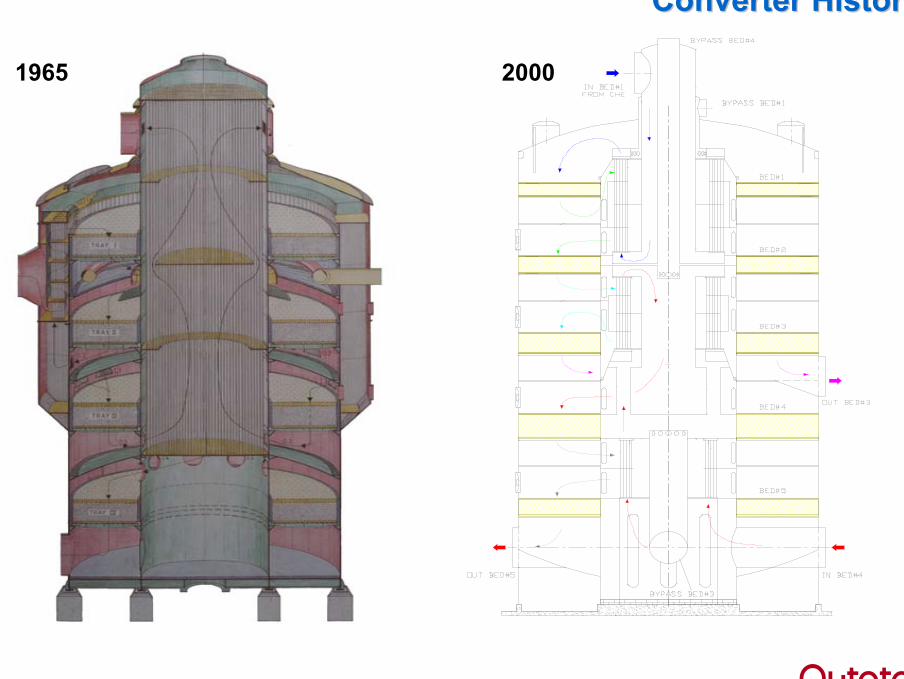
Converter HistoryConverter History
1965 2000
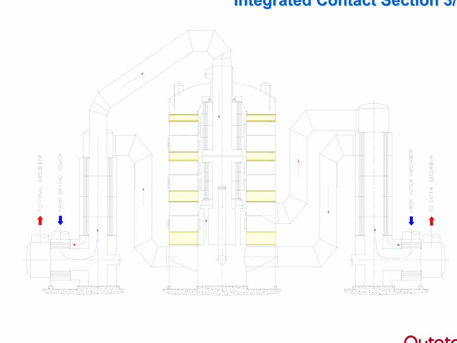
Integrated Contact SectionIntegrated Contact Section 3/13/1
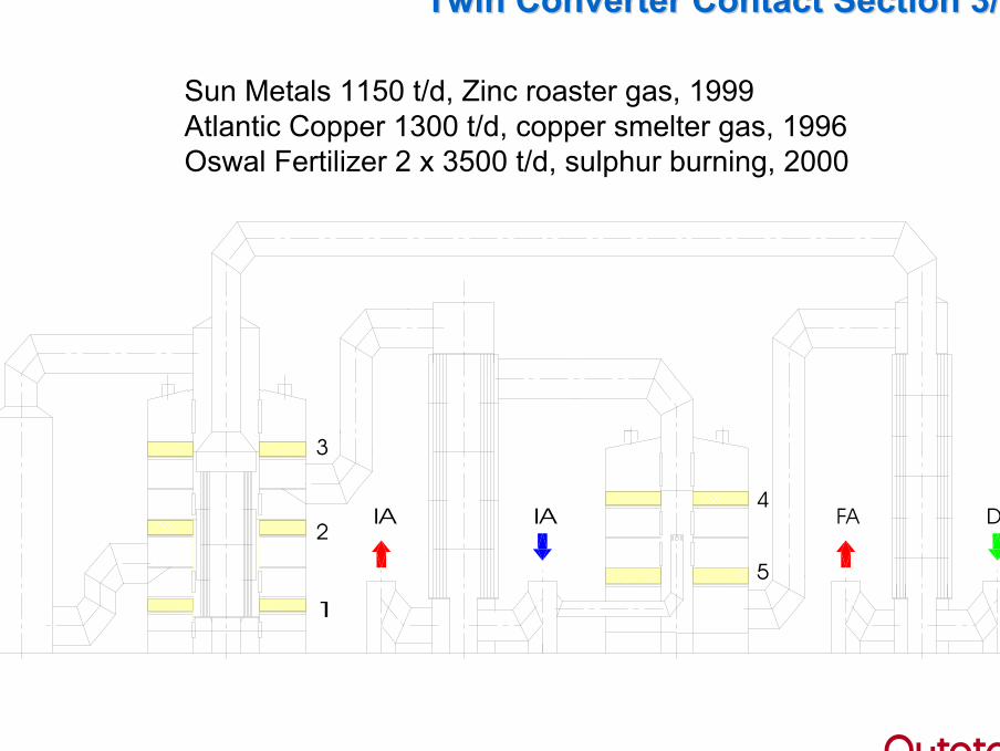
Twin Converter Contact SectionTwin Converter Contact Section 3/23/2
Sun Metals 1150 t/d, Zinc roaster gas, 1999Atlantic Copper 1300 t/d, copper smelter gas, 1996Oswal Fertilizer 2 x 3500 t/d, sulphur burning, 2000
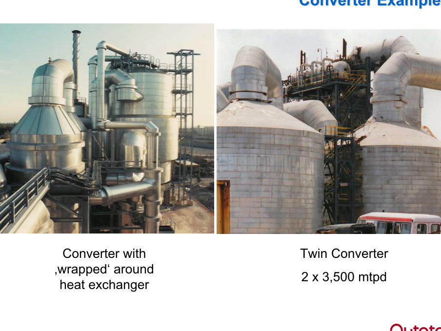
Twin Converter
2 x 3,500 mtpd
Converter ExamplesConverter Examples
Converter with‚wrapped‘ aroundheat exchanger
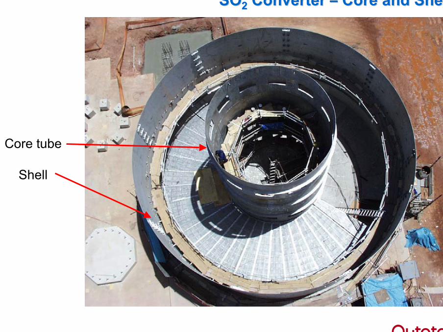
SOSO22 ConverterConverter –– CoreCore and Shelland Shell
Core tube
Shell
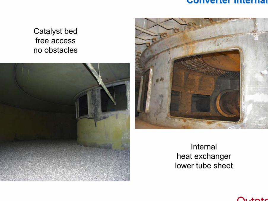
Converter InternalsConverter Internals
Catalyst bedfree accessno obstacles
Internalheat exchangerlower tube sheet
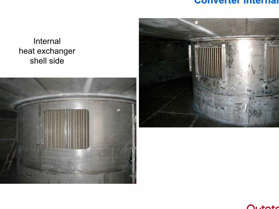
Converter InternalsConverter Internals
Internalheat exchanger
shell side
Converter InternalsConverter Internals
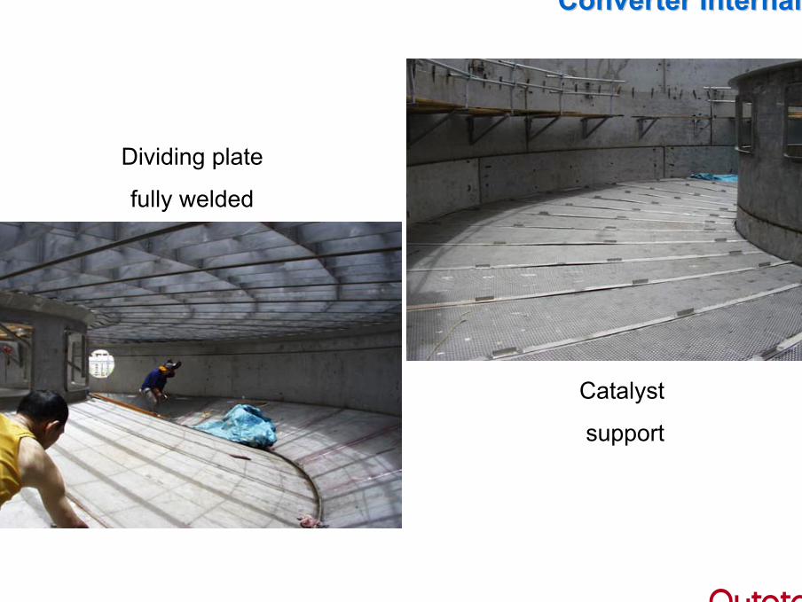
Dividing plate
fully welded
Catalyst
support
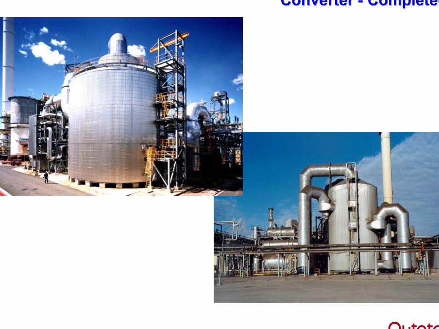
ConverterConverter -- CompletedCompleted
41 | 09 September 2009 | Vedanta – Sterlite Industries India41 | 09 September 2009 | BHP – Olympic Dam
www.outotec.com
Thank you forThank you foryour attentionyour attention !!