Embed Size (px)
Citation preview
mm/dd/yy
1
Lunch & Learn:
Designing and Simulating
Products for 3D Printing
How to Start Using the Technology to Make
Your Production Products
Eric Miller
PADT
2/3/2015
mm/dd/yy
2
Agenda
• Introductions
• Preamble
• Review of Additive Manufacturing
• Design Guidelines
• Simulation for Additive Manufacturing
• What Next?
• Q&A
Note:
We will publish these slides on our blog:
www.padtinc.com/blog
Expect a more in-depth version as a webinar in a month or two
mm/dd/yy
3
INTRODUCTIONS
mm/dd/yy
4
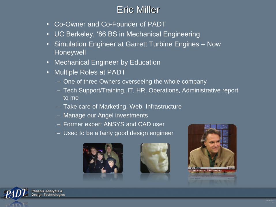
Eric Miller
• Co-Owner and Co-Founder of PADT
• UC Berkeley, ‘86 BS in Mechanical Engineering
• Simulation Engineer at Garrett Turbine Engines – Now
Honeywell
• Mechanical Engineer by Education
• Multiple Roles at PADT
– One of three Owners overseeing the whole company
– Tech Support/Training, IT, HR, Operations, Administrative report
to me
– Take care of Marketing, Web, Infrastructure
– Manage our Angel investments
– Former expert ANSYS and CAD user
– Used to be a fairly good design engineer
mm/dd/yy
5
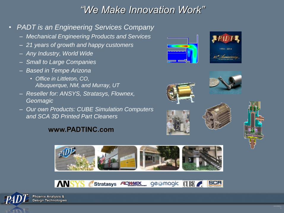
“We Make Innovation Work”
• PADT is an Engineering Services Company
– Mechanical Engineering Products and Services
– 21 years of growth and happy customers
– Any Industry, World Wide
– Small to Large Companies
– Based in Tempe Arizona
• Office in Littleton, CO,
Albuquerque, NM, and Murray, UT
– Reseller for: ANSYS, Stratasys, Flownex,
Geomagic
– Our own Products: CUBE Simulation Computers
and SCA 3D Printed Part Cleaners
mm/dd/yy
6
1000’s of Customers
mm/dd/yy
7
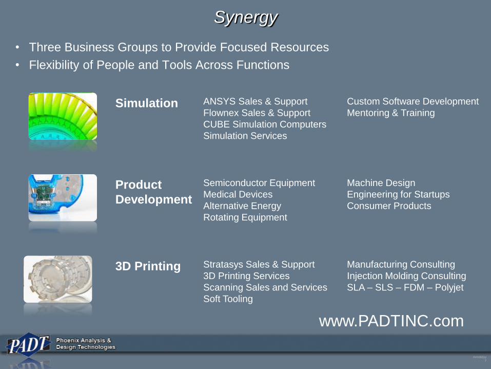
Synergy
• Three Business Groups to Provide Focused Resources
• Flexibility of People and Tools Across Functions
www.PADTINC.com
Product
Development
3D Printing
Simulation ANSYS Sales & Support
Flownex Sales & Support
CUBE Simulation Computers
Simulation Services
Custom Software Development
Mentoring & Training
Semiconductor Equipment
Medical Devices
Alternative Energy
Rotating Equipment
Machine Design
Engineering for Startups
Consumer Products
Stratasys Sales & Support
3D Printing Services
Scanning Sales and Services
Soft Tooling
Manufacturing Consulting
Injection Molding Consulting
SLA – SLS – FDM – Polyjet
mm/dd/yy
8
Preamble
mm/dd/yy
9
This is Not a Transporter from Star Trek
mm/dd/yy
10
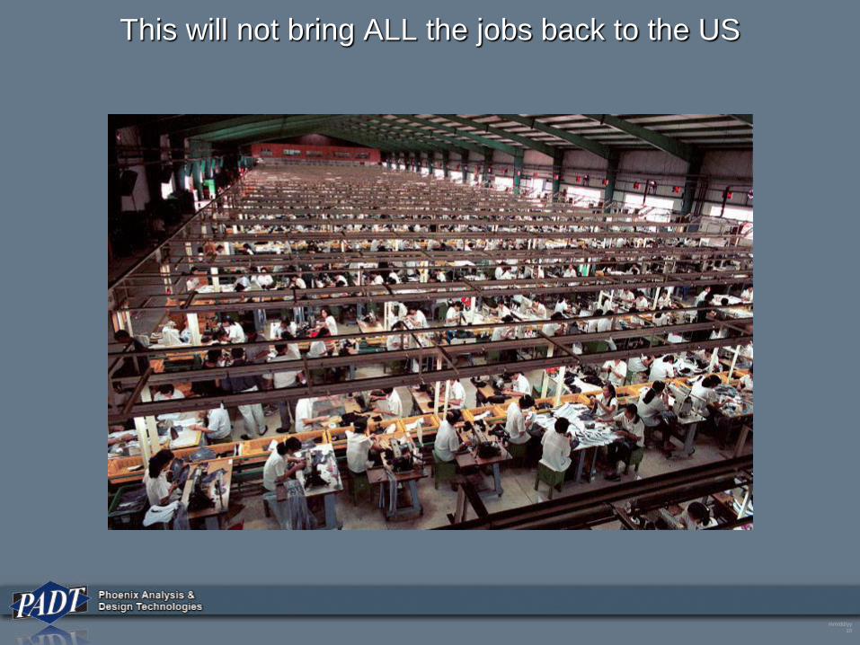
This will not bring ALL the jobs back to the US
mm/dd/yy
11
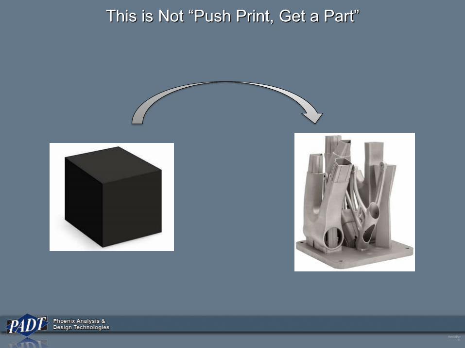
This is Not “Push Print, Get a Part”
mm/dd/yy
12
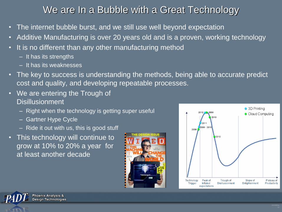
We are In a Bubble with a Great Technology
• The internet bubble burst, and we still use well beyond expectation
• Additive Manufacturing is over 20 years old and is a proven, working technology
• It is no different than any other manufacturing method
– It has its strengths
– It has its weaknesses
• The key to success is understanding the methods, being able to accurate predict
cost and quality, and developing repeatable processes.
• We are entering the Trough of
Disillusionment
– Right when the technology is getting super useful
– Gartner Hype Cycle
– Ride it out with us, this is good stuff
• This technology will continue to
grow at 10% to 20% a year for
at least another decade
mm/dd/yy
13
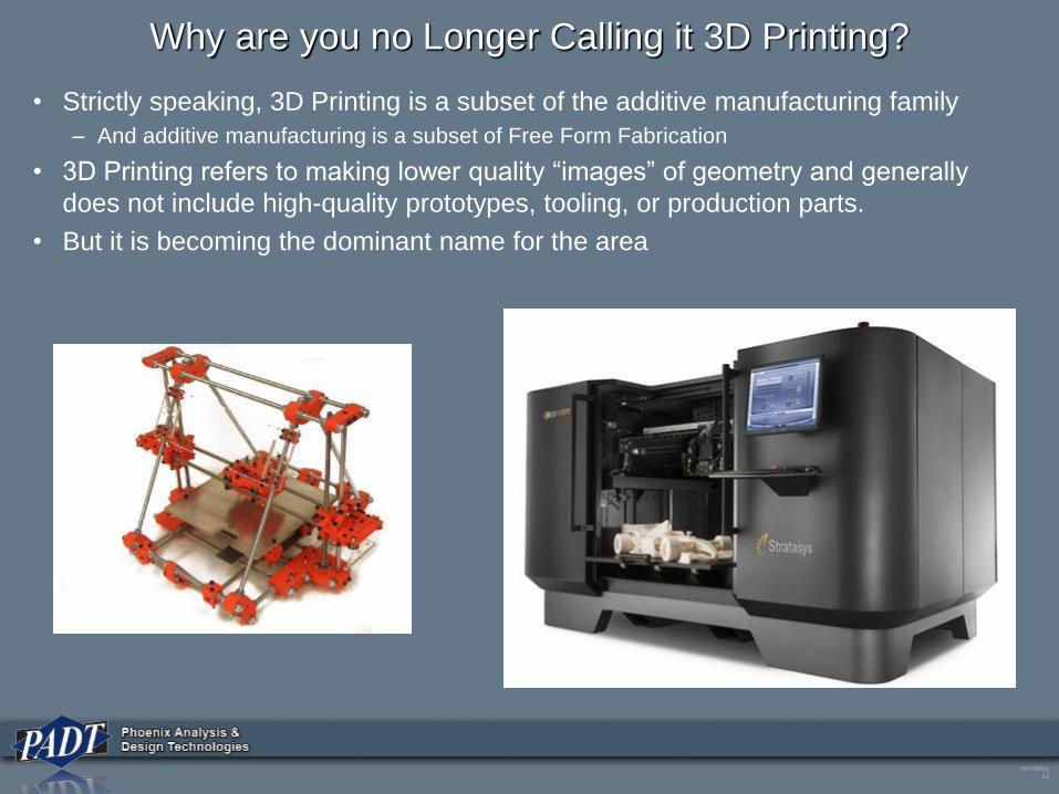
Why are you no Longer Calling it 3D Printing?
• Strictly speaking, 3D Printing is a subset of the additive manufacturing family
– And additive manufacturing is a subset of Free Form Fabrication
• 3D Printing refers to making lower quality “images” of geometry and generally
does not include high-quality prototypes, tooling, or production parts.
• But it is becoming the dominant name for the area
mm/dd/yy
14
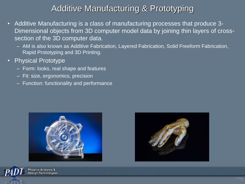
Additive Manufacturing & Prototyping
• Additive Manufacturing is a class of manufacturing processes that produce 3-
Dimensional objects from 3D computer model data by joining thin layers of cross-
section of the 3D computer data.
– AM is also known as Additive Fabrication, Layered Fabrication, Solid Freeform Fabrication,
Rapid Prototyping and 3D Printing.
• Physical Prototype
– Form: looks, real shape and features
– Fit: size, ergonomics, precision
– Function: functionality and performance
mm/dd/yy
15
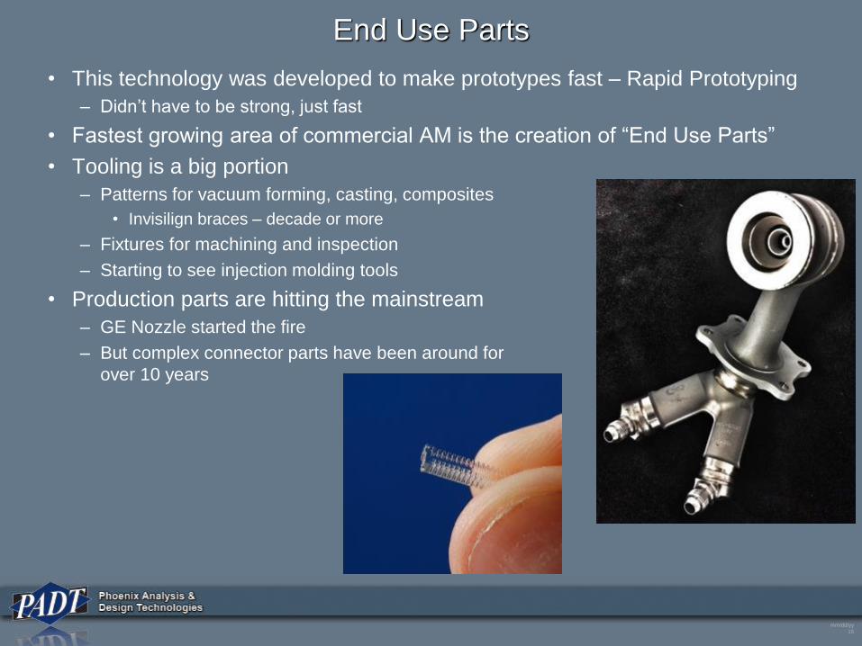
End Use Parts
• This technology was developed to make prototypes fast – Rapid Prototyping
– Didn’t have to be strong, just fast
• Fastest growing area of commercial AM is the creation of “End Use Parts”
• Tooling is a big portion
– Patterns for vacuum forming, casting, composites
• Invisilign braces – decade or more
– Fixtures for machining and inspection
– Starting to see injection molding tools
• Production parts are hitting the mainstream
– GE Nozzle started the fire
– But complex connector parts have been around for
over 10 years
mm/dd/yy
16
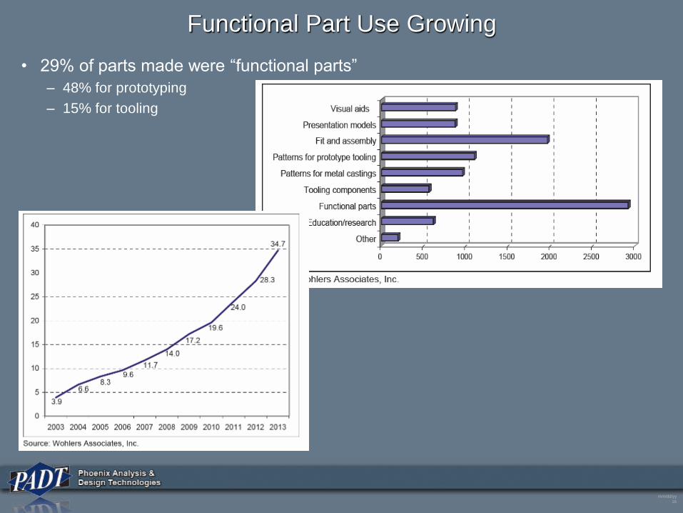
Functional Part Use Growing
• 29% of parts made were “functional parts”
– 48% for prototyping
– 15% for tooling
mm/dd/yy
17
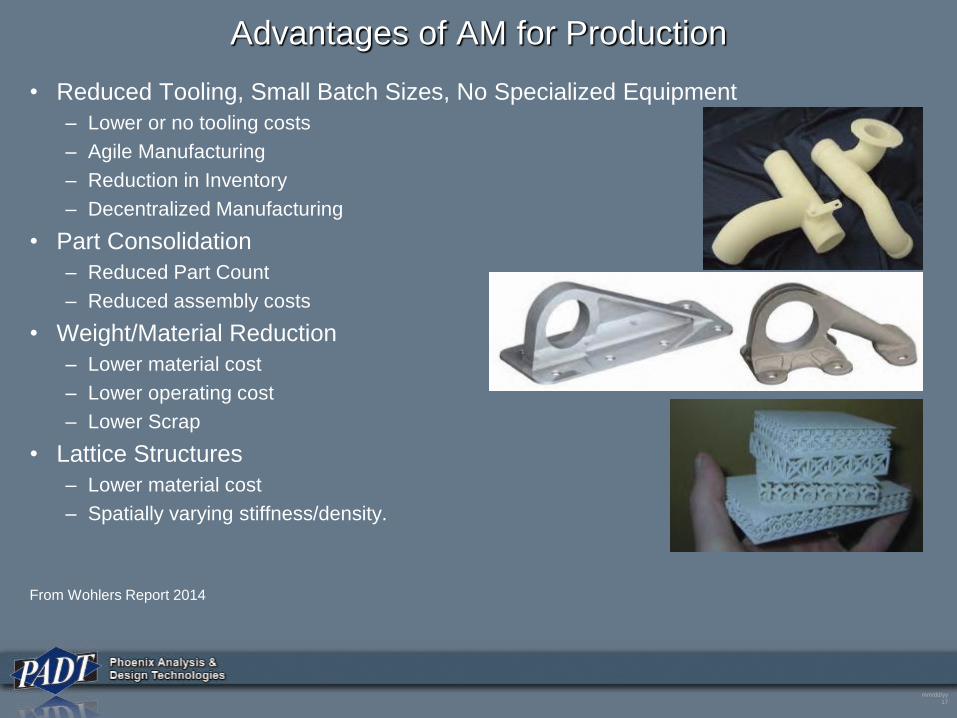
Advantages of AM for Production
• Reduced Tooling, Small Batch Sizes, No Specialized Equipment
– Lower or no tooling costs
– Agile Manufacturing
– Reduction in Inventory
– Decentralized Manufacturing
• Part Consolidation
– Reduced Part Count
– Reduced assembly costs
• Weight/Material Reduction
– Lower material cost
– Lower operating cost
– Lower Scrap
• Lattice Structures
– Lower material cost
– Spatially varying stiffness/density.
From Wohlers Report 2014
mm/dd/yy
18
REVIEW OF ADDITIVE MANUFACTURING
mm/dd/yy
19
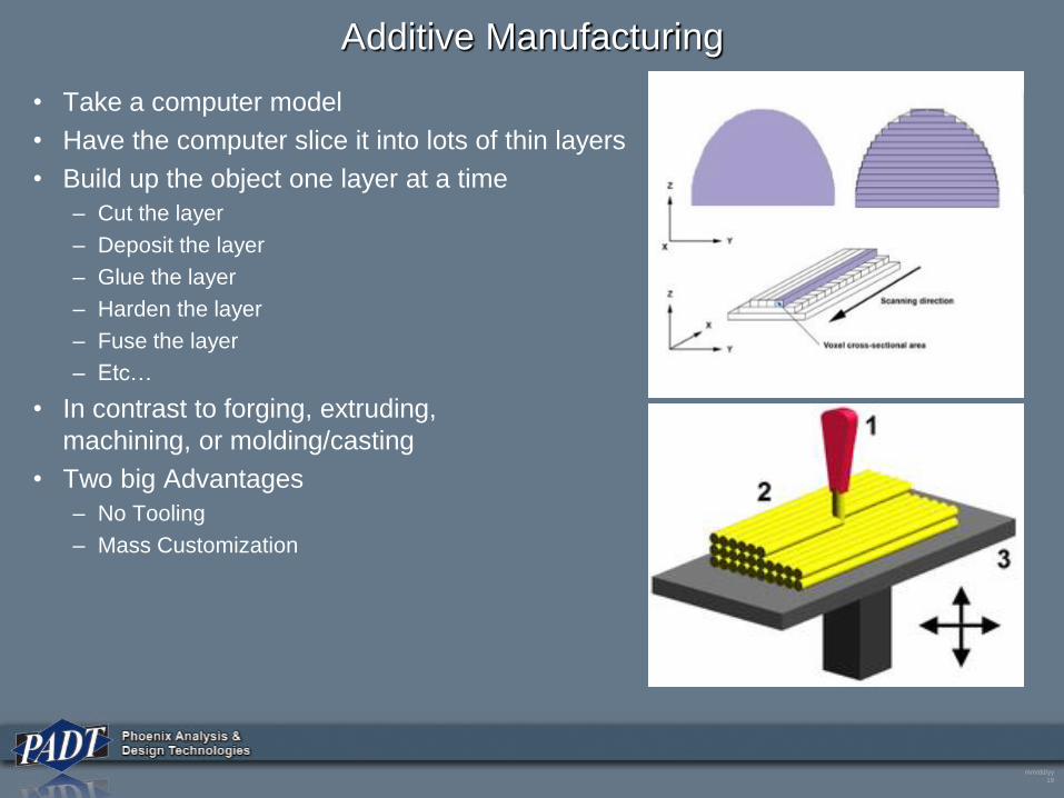
Additive Manufacturing
• Take a computer model
• Have the computer slice it into lots of thin layers
• Build up the object one layer at a time
– Cut the layer
– Deposit the layer
– Glue the layer
– Harden the layer
– Fuse the layer
– Etc…
• In contrast to forging, extruding,
machining, or molding/casting
• Two big Advantages
– No Tooling
– Mass Customization
mm/dd/yy
20
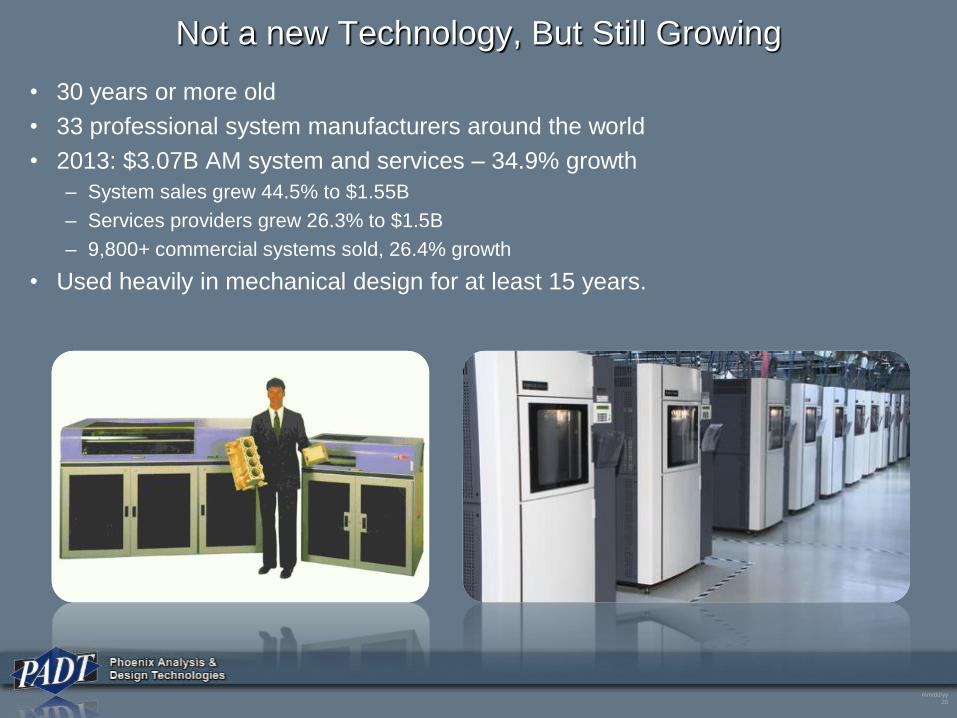
Not a new Technology, But Still Growing
• 30 years or more old
• 33 professional system manufacturers around the world
• 2013: $3.07B AM system and services – 34.9% growth
– System sales grew 44.5% to $1.55B
– Services providers grew 26.3% to $1.5B
– 9,800+ commercial systems sold, 26.4% growth
• Used heavily in mechanical design for at least 15 years.
mm/dd/yy
21
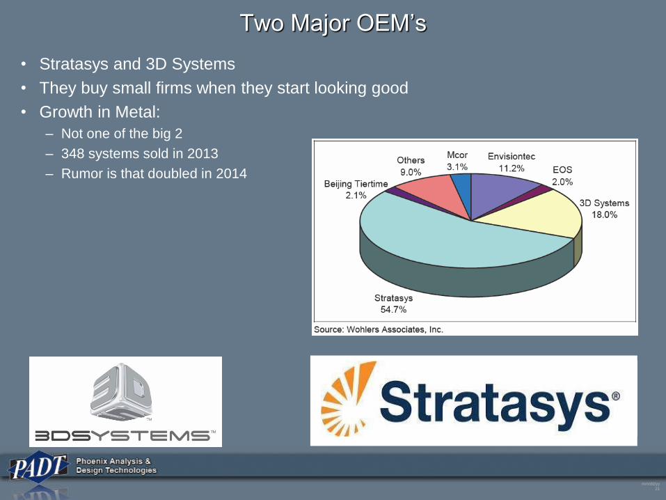
Two Major OEM’s
• Stratasys and 3D Systems
• They buy small firms when they start looking good
• Growth in Metal:
– Not one of the big 2
– 348 systems sold in 2013
– Rumor is that doubled in 2014
mm/dd/yy
22
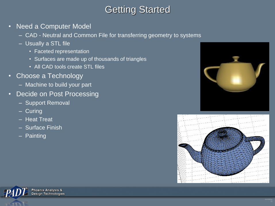
Getting Started
• Need a Computer Model
– CAD - Neutral and Common File for transferring geometry to systems
– Usually a STL file
• Faceted representation
• Surfaces are made up of thousands of triangles
• All CAD tools create STL files
• Choose a Technology
– Machine to build your part
• Decide on Post Processing
– Support Removal
– Curing
– Heat Treat
– Surface Finish
– Painting
mm/dd/yy
23
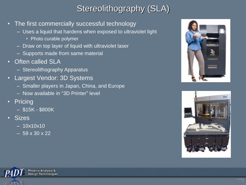
Stereolithography (SLA)
• The first commercially successful technology
– Uses a liquid that hardens when exposed to ultraviolet light
• Photo curable polymer
– Draw on top layer of liquid with ultraviolet laser
– Supports made from same material
• Often called SLA
– Stereolithography Apparatus
• Largest Vendor: 3D Systems
– Smaller players in Japan, China, and Europe
– Now available in “3D Printer” level
• Pricing
– $15K - $800K
• Sizes
– 10x10x10
– 59 x 30 x 22
mm/dd/yy
2424
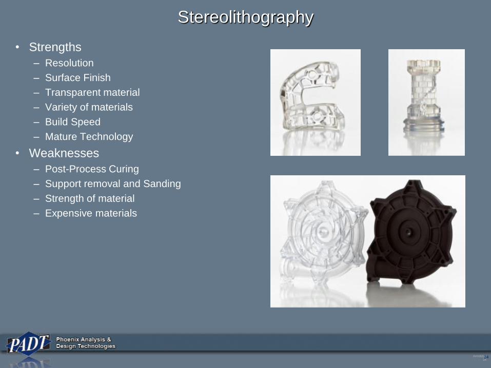
Stereolithography
• Strengths
– Resolution
– Surface Finish
– Transparent material
– Variety of materials
– Build Speed
– Mature Technology
• Weaknesses
– Post-Process Curing
– Support removal and Sanding
– Strength of material
– Expensive materials
mm/dd/yy
2525
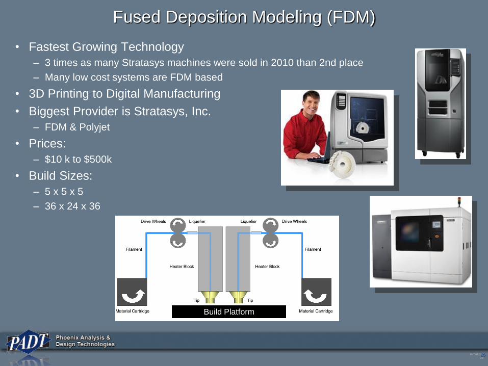
Fused Deposition Modeling (FDM)
• Fastest Growing Technology
– 3 times as many Stratasys machines were sold in 2010 than 2nd place
– Many low cost systems are FDM based
• 3D Printing to Digital Manufacturing
• Biggest Provider is Stratasys, Inc.
– FDM & Polyjet
• Prices:
– $10 k to $500k
• Build Sizes:
– 5 x 5 x 5
– 36 x 24 x 36
Build Platform
mm/dd/yy
2626
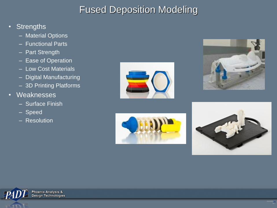
Fused Deposition Modeling
• Strengths
– Material Options
– Functional Parts
– Part Strength
– Ease of Operation
– Low Cost Materials
– Digital Manufacturing
– 3D Printing Platforms
• Weaknesses
– Surface Finish
– Speed
– Resolution
mm/dd/yy
2727
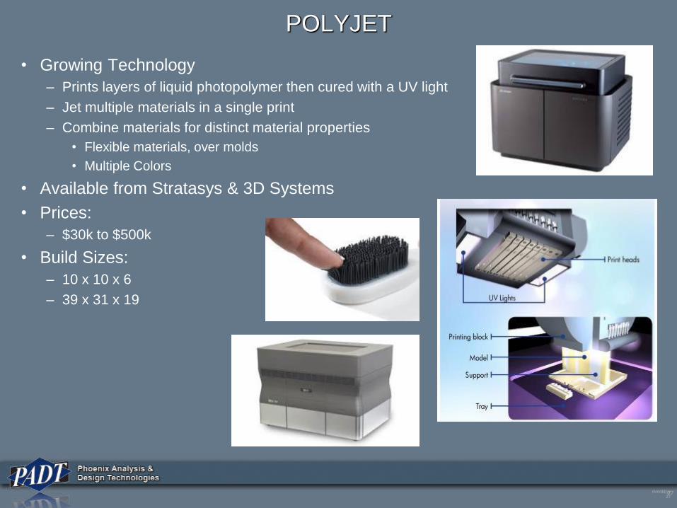
POLYJET
• Growing Technology
– Prints layers of liquid photopolymer then cured with a UV light
– Jet multiple materials in a single print
– Combine materials for distinct material properties
• Flexible materials, over molds
• Multiple Colors
• Available from Stratasys & 3D Systems
• Prices:
– $30k to $500k
• Build Sizes:
– 10 x 10 x 6
– 39 x 31 x 19
mm/dd/yy
2828
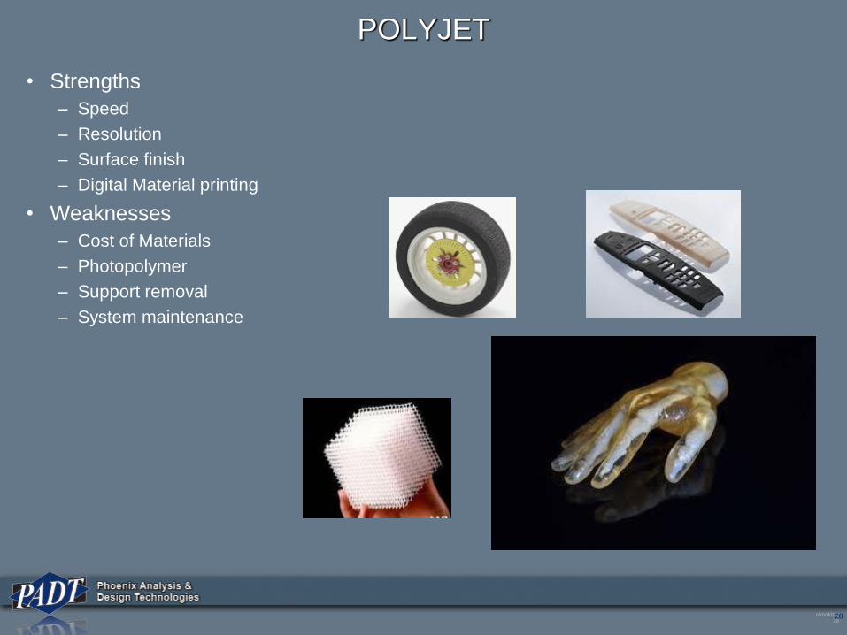
POLYJET
• Strengths
– Speed
– Resolution
– Surface finish
– Digital Material printing
• Weaknesses
– Cost of Materials
– Photopolymer
– Support removal
– System maintenance
mm/dd/yy
2929
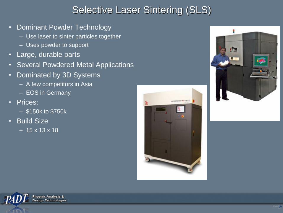
Selective Laser Sintering (SLS)
• Dominant Powder Technology
– Use laser to sinter particles together
– Uses powder to support
• Large, durable parts
• Several Powdered Metal Applications
• Dominated by 3D Systems
– A few competitors in Asia
– EOS in Germany
• Prices:
– $150k to $750k
• Build Size
– 15 x 13 x 18
mm/dd/yy
3030
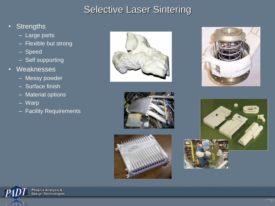
Selective Laser Sintering
• Strengths
– Large parts
– Flexible but strong
– Speed
– Self supporting
• Weaknesses
– Messy powder
– Surface finish
– Material options
– Warp
– Facility Requirements
mm/dd/yy
31
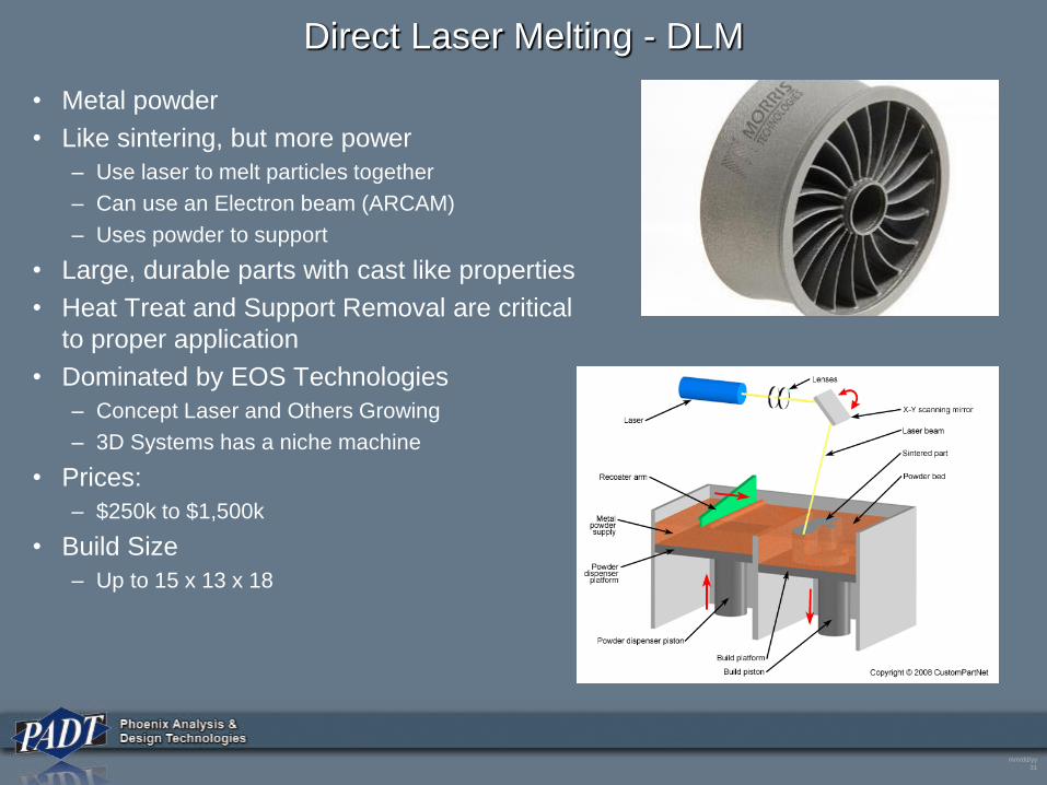
Direct Laser Melting - DLM
• Metal powder
• Like sintering, but more power
– Use laser to melt particles together
– Can use an Electron beam (ARCAM)
– Uses powder to support
• Large, durable parts with cast like properties
• Heat Treat and Support Removal are critical
to proper application
• Dominated by EOS Technologies
– Concept Laser and Others Growing
– 3D Systems has a niche machine
• Prices:
– $250k to $1,500k
• Build Size
– Up to 15 x 13 x 18
mm/dd/yy
3232
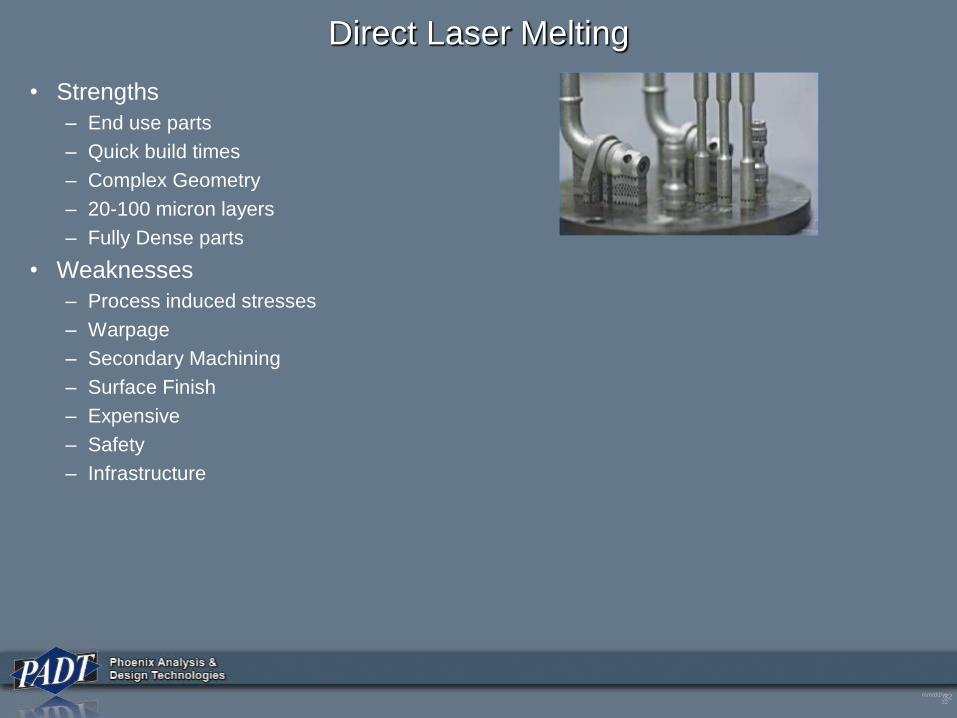
Direct Laser Melting
• Strengths
– End use parts
– Quick build times
– Complex Geometry
– 20-100 micron layers
– Fully Dense parts
• Weaknesses
– Process induced stresses
– Warpage
– Secondary Machining
– Surface Finish
– Expensive
– Safety
– Infrastructure

mm/dd/yy
33
Other
• Binding
– Inkjet print glue into a powder
– Great for casting patterns or ceramic green parts (ExOne)
– Color can be added to binder (Zcorp)
– Parts are not strong and can shrink
• Welding
– CNC controlled welding machine - Metal FDM
– Lots of post processing required
• Layered Object Manufacturing (LOM)
– Stack sheets of material, cutting as you go
– Paper, plastic, even sheet metal
– Delamination and how to remove material a problem
• Direct Energy Deposition
– Blow powder into focal point of multiple Laser Beams
– Great for adding material, but not super accurate
• Hybrid
– Combine an AM process with CNC machining
– Great for processes with poor accuracy/surface finish
– AM adds material, CNC shapes it.
mm/dd/yy
34
Design Guidelines
mm/dd/yy
35
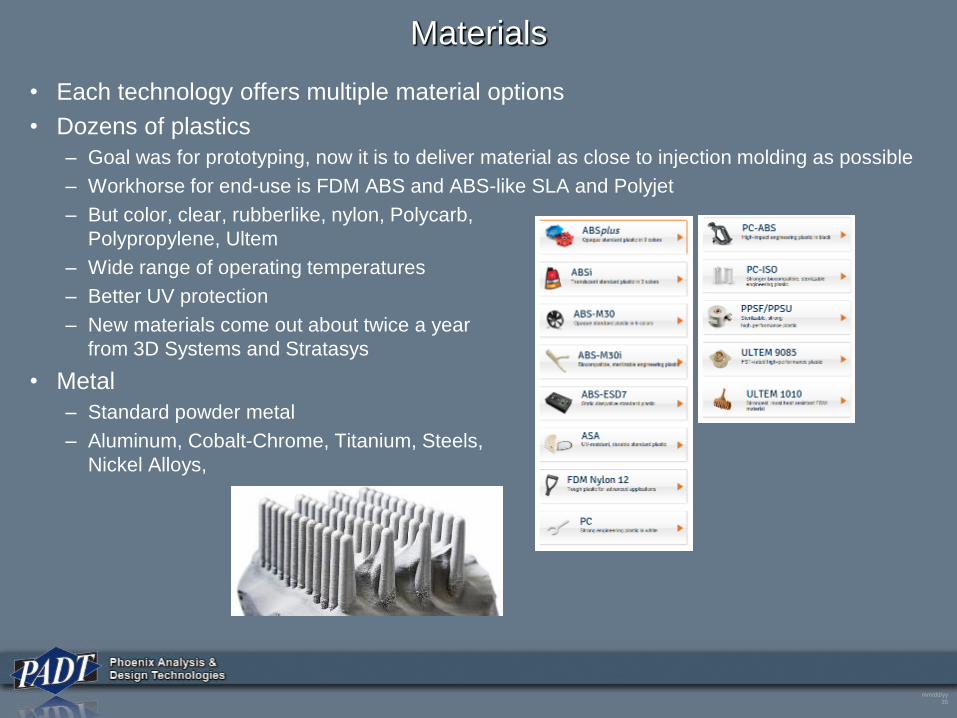
Materials
• Each technology offers multiple material options
• Dozens of plastics
– Goal was for prototyping, now it is to deliver material as close to injection molding as possible
– Workhorse for end-use is FDM ABS and ABS-like SLA and Polyjet
– But color, clear, rubberlike, nylon, Polycarb,
Polypropylene, Ultem
– Wide range of operating temperatures
– Better UV protection
– New materials come out about twice a year
from 3D Systems and Stratasys
• Metal
– Standard powder metal
– Aluminum, Cobalt-Chrome, Titanium, Steels,
Nickel Alloys,
mm/dd/yy
36
Material Selection
• For end-use you need to consider:– Strength
– Stiffness
– Poison’s Ratio (?)
– Environment• UV
• Temperature
• Chemicals
– Aesthetics
• Make samples of typical geometry – The flat coupons are not representative
– Make initial parts in several materials and test
mm/dd/yy
37
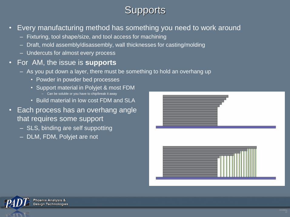
Supports
• Every manufacturing method has something you need to work around– Fixturing, tool shape/size, and tool access for machining
– Draft, mold assembly/disassembly, wall thicknesses for casting/molding
– Undercuts for almost every process
• For AM, the issue is supports– As you put down a layer, there must be something to hold an overhang up
• Powder in powder bed processes
• Support material in Polyjet & most FDM– Can be soluble or you have to chip/break it away
• Build material in low cost FDM and SLA
• Each process has an overhang angle
that requires some support
– SLS, binding are self suppotting
– DLM, FDM, Polyjet are not
mm/dd/yy
38
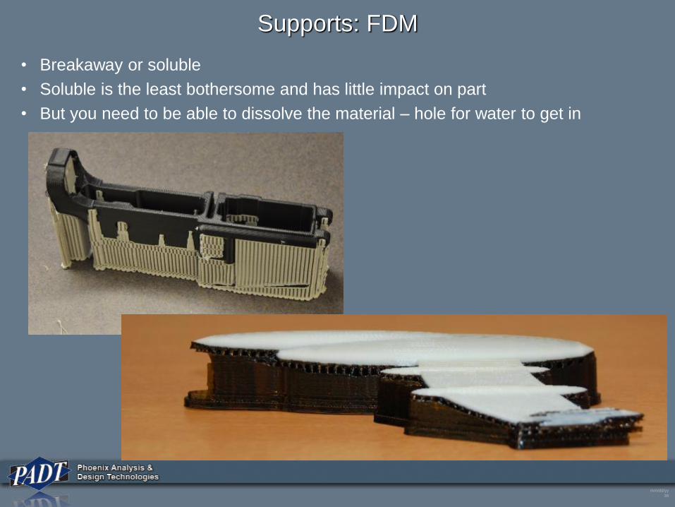
Supports: FDM
• Breakaway or soluble
• Soluble is the least bothersome and has little impact on part
• But you need to be able to dissolve the material – hole for water to get in
mm/dd/yy
39
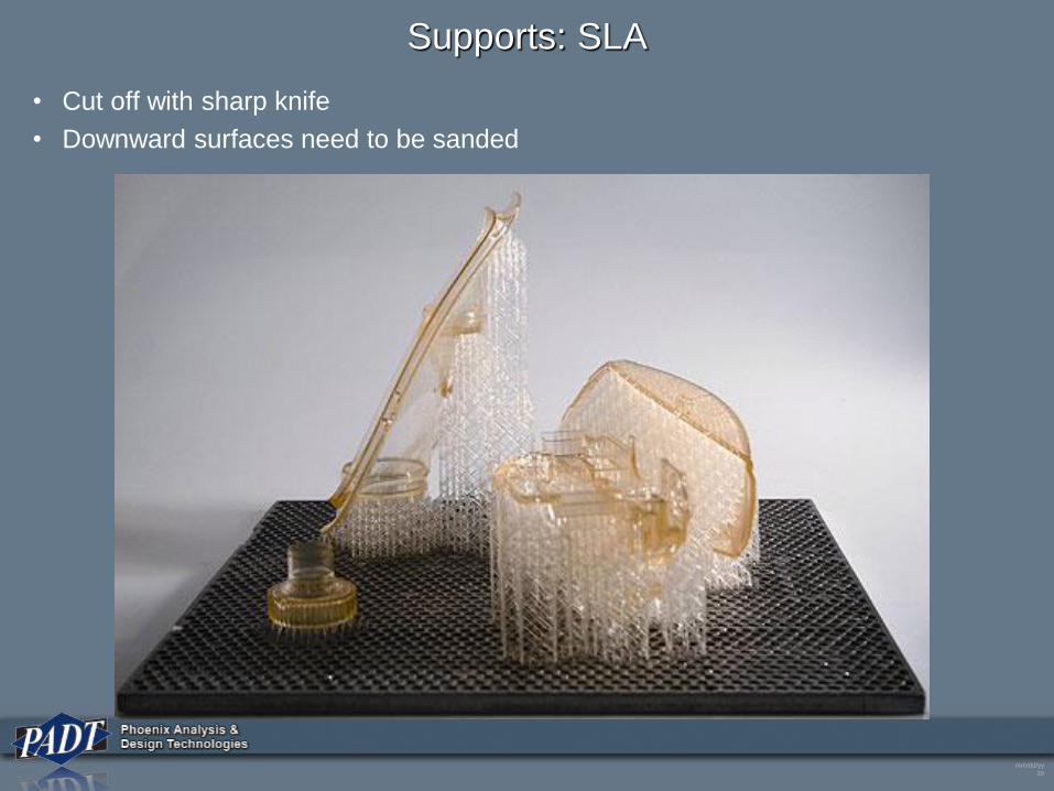
Supports: SLA
• Cut off with sharp knife
• Downward surfaces need to be sanded
mm/dd/yy
40
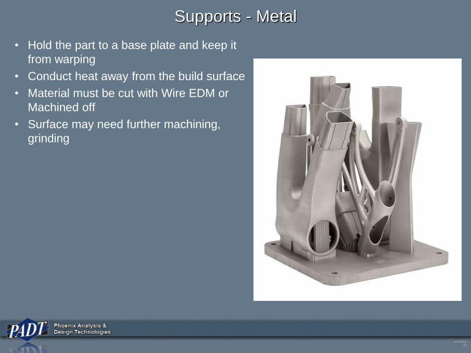
Supports - Metal
• Hold the part to a base plate and keep it
from warping
• Conduct heat away from the build surface
• Material must be cut with Wire EDM or
Machined off
• Surface may need further machining,
grinding
mm/dd/yy
41
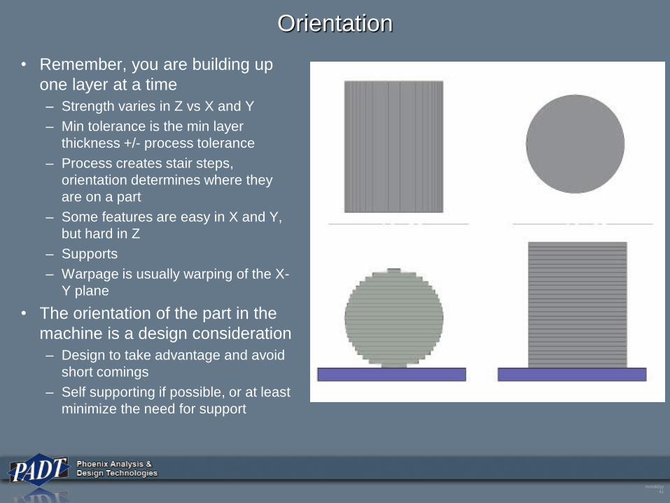
Orientation
• Remember, you are building up
one layer at a time
– Strength varies in Z vs X and Y
– Min tolerance is the min layer
thickness +/- process tolerance
– Process creates stair steps,
orientation determines where they
are on a part
– Some features are easy in X and Y,
but hard in Z
– Supports
– Warpage is usually warping of the X-
Y plane
• The orientation of the part in the
machine is a design consideration
– Design to take advantage and avoid
short comings
– Self supporting if possible, or at least
minimize the need for support
mm/dd/yy
42
Supports – Design Issues
• How Supports are removed is important
– Manual for most processes - Cost
– Impacts surface finish where supports touch part
– Need access to get supports out even if powder or soluble
– Removal may damage the part or change its shape
mm/dd/yy
43
Machine Constraints
• Remember – Layers and droplet/beam/bead thicknesses
– Not like machining where you can have any value +/- tolerance
– Dimensions are discrete
• Layer thickness for Z direction
• Resolution of thing making material on the X-Y plane
• Tolerances are not as tight as traditional
– Little secret:
• Stated tolerance is usually over an inch on the X-Y Plane
• Tolerance from one end of the build area to another is much less accurate.
• Shrinkage in curing/heat treat, residual stresses, machine accuracy
• Creep
• Design parts so that you do not care about discrete distances
– Easy to say, hard to do
• Use machining of critical surfaces/holes if needed
mm/dd/yy
44
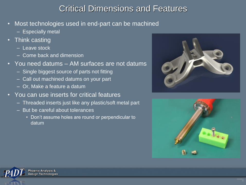
Critical Dimensions and Features
• Most technologies used in end-part can be machined
– Especially metal
• Think casting
– Leave stock
– Come back and dimension
• You need datums – AM surfaces are not datums
– Single biggest source of parts not fitting
– Call out machined datums on your part
– Or, Make a feature a datum
• You can use inserts for critical features
– Threaded inserts just like any plastic/soft metal part
– But be careful about tolerances
• Don’t assume holes are round or perpendicular to
datum
mm/dd/yy
45
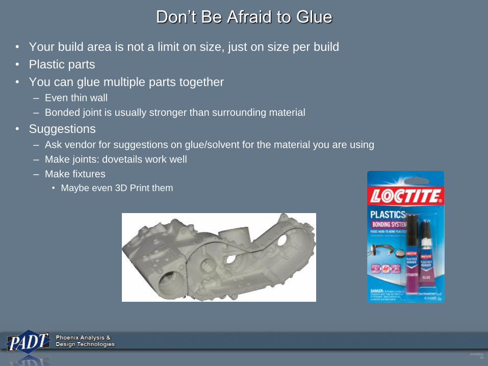
Don’t Be Afraid to Glue
• Your build area is not a limit on size, just on size per build
• Plastic parts
• You can glue multiple parts together
– Even thin wall
– Bonded joint is usually stronger than surrounding material
• Suggestions
– Ask vendor for suggestions on glue/solvent for the material you are using
– Make joints: dovetails work well
– Make fixtures
• Maybe even 3D Print them
mm/dd/yy
46
Drawings
• Direct from computer to printer gets people thinking about no drawings
• Remember what drawings are for:
– Capture information that manufacturing and quality need to make the right part
• End use parts need drawings!
– Can be a text document
– But if you are measuring dimensions/GDT, you need some pictures.
• You should develop a drawing standard for AM Parts
– Develop shop floor standards and reference those in notes
– Develop inspection standards and call those out
• Assume a stranger is making the part, everything they need to know must be on
the drawing
– The STL file and the drawing should fully define and control the part from creation to shipping
• Manufacturing should develop standard for process planning
– Standardized routers for each technology, including pre- and post-processing
• Important: the build instructions (tool path) should be a controlled document, just
like CNC code.
– Repeatability and tractability.
mm/dd/yy
47
Drawings
• What to include:
– Material specification
– Orientation!
– Support parameters
– Acceptable machine parameters
• Or specific parameters to use
• Based on assumptions in design
– Post processing
• Support removal
• Washing
• Final curing
• Sanding/grit blasting, etc…
– Heat Treat
– Storage constraints (temp, humidity, etc…)
– Surface finish
– Painting/coating
– Dimensions
• Datums
• Inspection points for acceptable
warping/distortion
• Key features – especially machined
features
– Part marking
– Lot documenting instructions
• Group by machine build, material lot,
and/or production run
– Other tractability
• Material lot info
• Parameters used in build
• Location of each part in build volume
mm/dd/yy
48
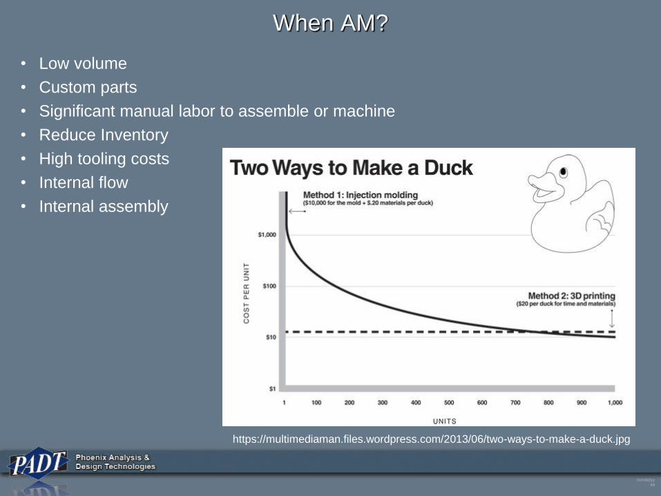
When AM?
• Low volume
• Custom parts
• Significant manual labor to assemble or machine
• Reduce Inventory
• High tooling costs
• Internal flow
• Internal assembly
https://multimediaman.files.wordpress.com/2013/06/two-ways-to-make-a-duck.jpg
mm/dd/yy
49
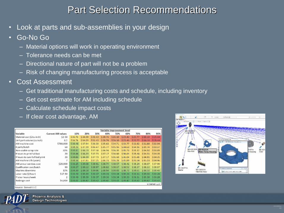
Part Selection Recommendations
• Look at parts and sub-assemblies in your design
• Go-No Go
– Material options will work in operating environment
– Tolerance needs can be met
– Directional nature of part will not be a problem
– Risk of changing manufacturing process is acceptable
• Cost Assessment
– Get traditional manufacturing costs and schedule, including inventory
– Get cost estimate for AM including schedule
– Calculate schedule impact costs
– If clear cost advantage, AM
mm/dd/yy
50
Design Checklist
Material
Supports - minimize and removal
Orientation - Build time, strength, stair stepping
Layer Thickness
Min Wall Thickness
Critical surfaces/holes
Surface Finish
Operating Environment
Capture requirements in a drawing
mm/dd/yy
51
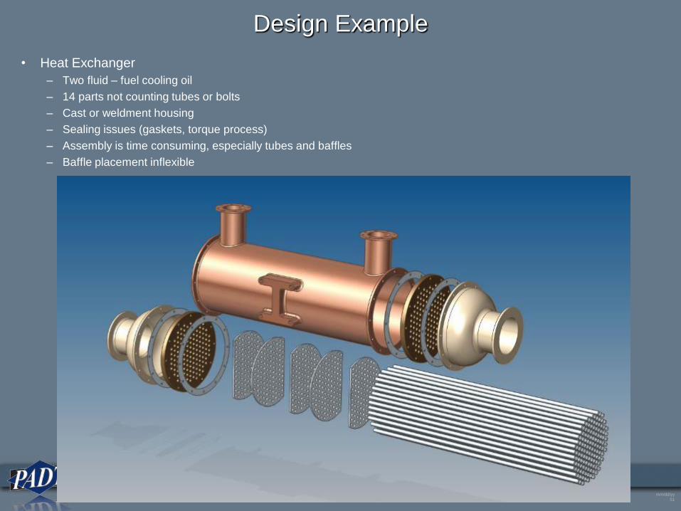
Design Example
• Heat Exchanger
– Two fluid – fuel cooling oil
– 14 parts not counting tubes or bolts
– Cast or weldment housing
– Sealing issues (gaskets, torque process)
– Assembly is time consuming, especially tubes and baffles
– Baffle placement inflexible
mm/dd/yy
52
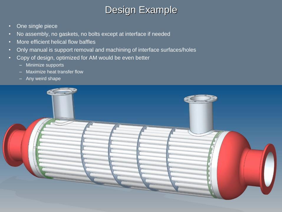
Design Example
• One single piece
• No assembly, no gaskets, no bolts except at interface if needed
• More efficient helical flow baffles
• Only manual is support removal and machining of interface surfaces/holes
• Copy of design, optimized for AM would be even better
– Minimize supports
– Maximize heat transfer flow
– Any weird shape
mm/dd/yy
53
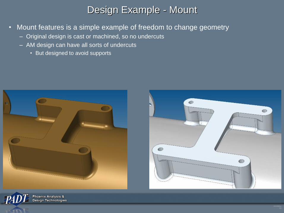
Design Example - Mount
• Mount features is a simple example of freedom to change geometry
– Original design is cast or machined, so no undercuts
– AM design can have all sorts of undercuts
• But designed to avoid supports
mm/dd/yy
54
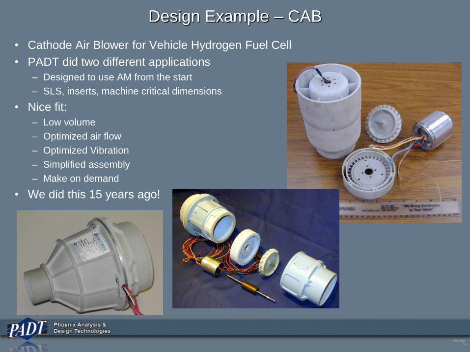
Design Example – CAB
• Cathode Air Blower for Vehicle Hydrogen Fuel Cell
• PADT did two different applications
– Designed to use AM from the start
– SLS, inserts, machine critical dimensions
• Nice fit:
– Low volume
– Optimized air flow
– Optimized Vibration
– Simplified assembly
– Make on demand
• We did this 15 years ago!
mm/dd/yy
55
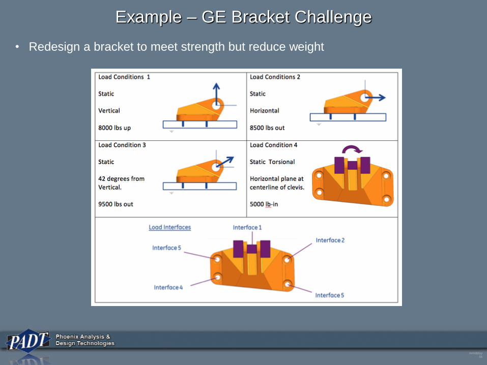
Example – GE Bracket Challenge
• Redesign a bracket to meet strength but reduce weight
mm/dd/yy
56
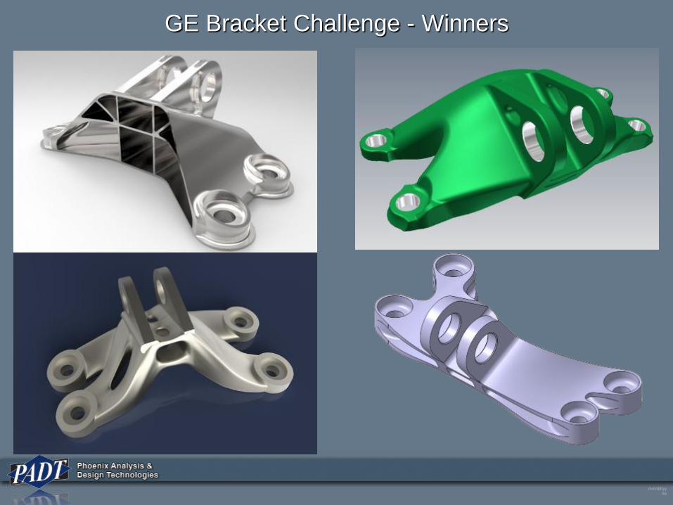
GE Bracket Challenge - Winners
mm/dd/yy
57
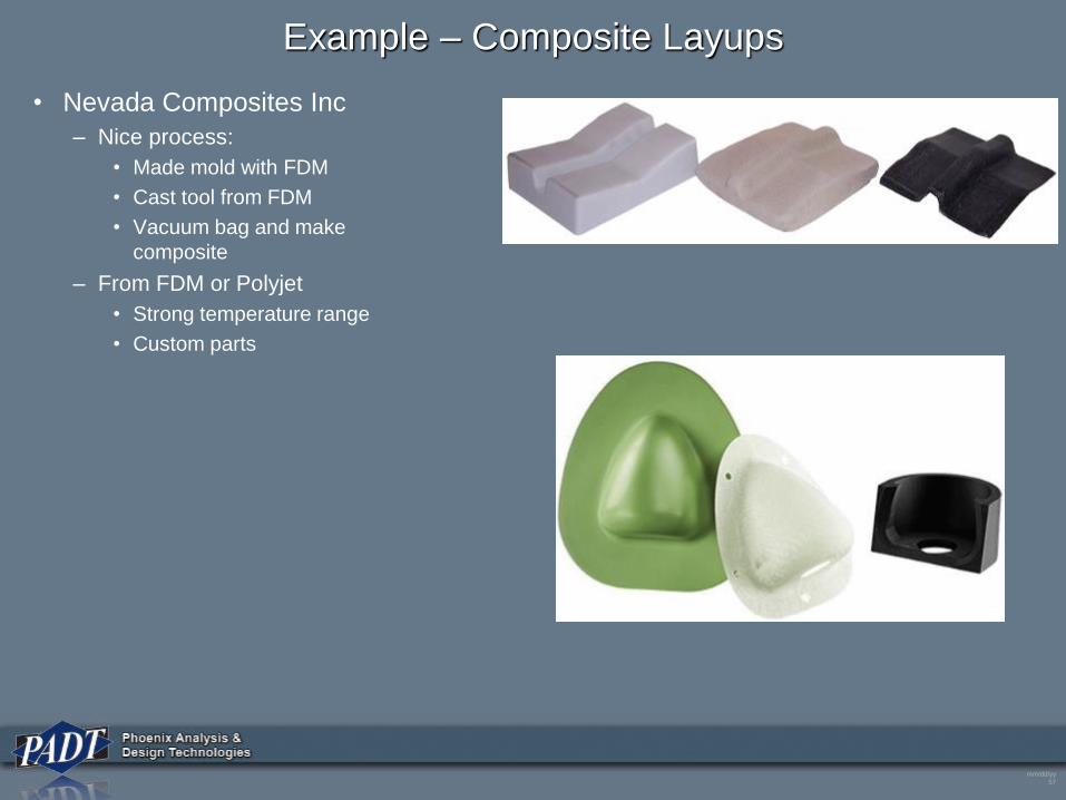
Example – Composite Layups
• Nevada Composites Inc
– Nice process:
• Made mold with FDM
• Cast tool from FDM
• Vacuum bag and make
composite
– From FDM or Polyjet
• Strong temperature range
• Custom parts
mm/dd/yy
58
Simulation for 3D Printing
mm/dd/yy
59
Two Areas: Process Simulation and Product Simulation
• Process Simulation
– Modeling the additive manufacturing process
– Determine the actual material distribution
• Pattern on each layer
• Stair steps
• Voids
– Predict residual stresses in part
• Critical for Metal
• Product Simulation
– Just like any part – predict behavior of the component or assembly
– Only difference is:
• isotropic or anisotropic material
• Actual voids in material
• Residual stresses
– Opportunity for more creative optimization
• Not constrained by traditional manufacturing
– FAA and FDA are allowing simulation for certification
• Even without certification, you want to reduce the number and cost of tests.
mm/dd/yy
60
Process Simulation
• No great tools for Polymers
– Much work being done – but no tools yet
– Testing and inspection is still needed to understand and capture impact of process on strength
and stiffness
• What you can do now
– Estimate Orthotropic properties
• Z vs X-Y
• Build test samples and measure
– Used Layered Solid (ANSYS Only)
• Make an estimate on stiffness in X and Y direction based on statistics
– Volume of material put down in each direction
– Need testing with material and machine to get approximate values
• Or use “zone” method
– Build sub-models of a “typical” material pattern
– Run model to get orthotropic properties
– Apply to patches of material on each layer, using closest “typical” pattern
– Method is used for lattice structures
mm/dd/yy
61
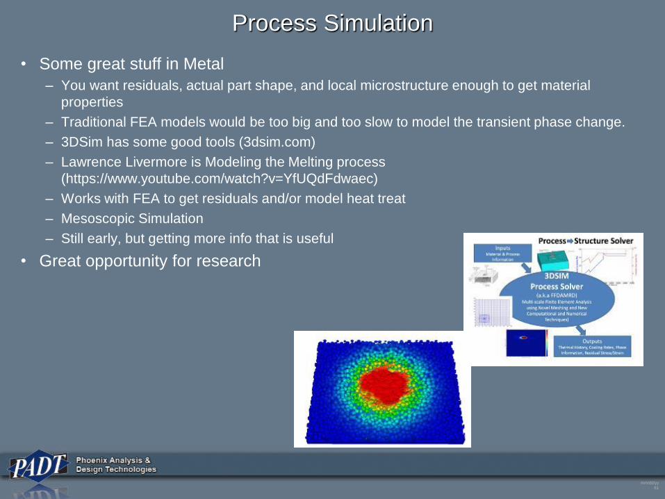
Process Simulation
• Some great stuff in Metal
– You want residuals, actual part shape, and local microstructure enough to get material
properties
– Traditional FEA models would be too big and too slow to model the transient phase change.
– 3DSim has some good tools (3dsim.com)
– Lawrence Livermore is Modeling the Melting process
(https://www.youtube.com/watch?v=YfUQdFdwaec)
– Works with FEA to get residuals and/or model heat treat
– Mesoscopic Simulation
– Still early, but getting more info that is useful
• Great opportunity for research
mm/dd/yy
62
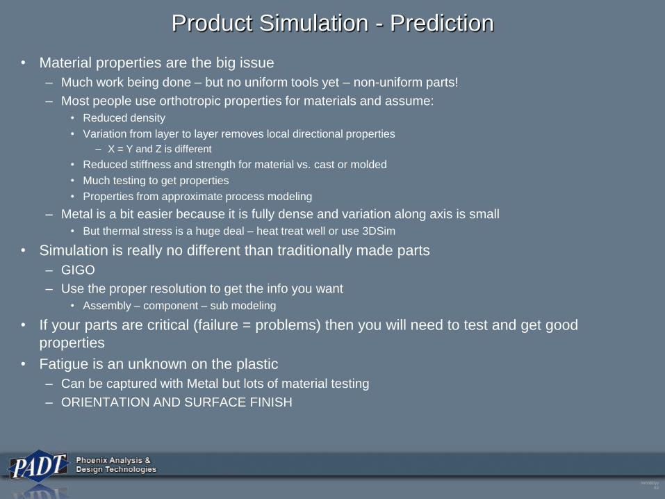
Product Simulation - Prediction
• Material properties are the big issue
– Much work being done – but no uniform tools yet – non-uniform parts!
– Most people use orthotropic properties for materials and assume:
• Reduced density
• Variation from layer to layer removes local directional properties
– X = Y and Z is different
• Reduced stiffness and strength for material vs. cast or molded
• Much testing to get properties
• Properties from approximate process modeling
– Metal is a bit easier because it is fully dense and variation along axis is small
• But thermal stress is a huge deal – heat treat well or use 3DSim
• Simulation is really no different than traditionally made parts
– GIGO
– Use the proper resolution to get the info you want
• Assembly – component – sub modeling
• If your parts are critical (failure = problems) then you will need to test and get good
properties
• Fatigue is an unknown on the plastic
– Can be captured with Metal but lots of material testing
– ORIENTATION AND SURFACE FINISH
mm/dd/yy
63
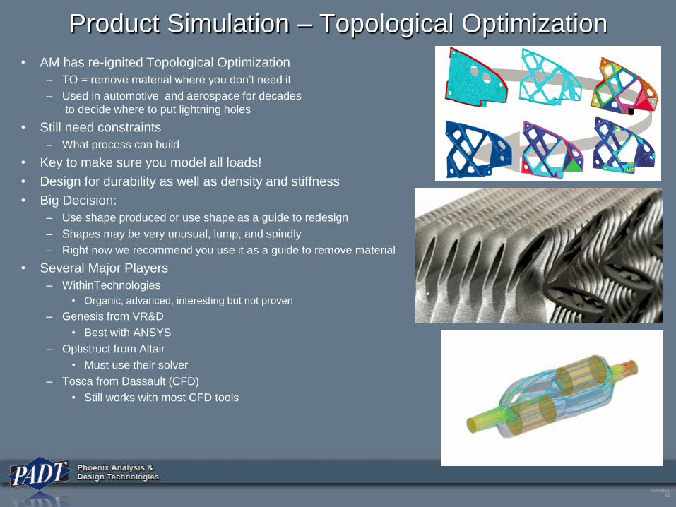
Product Simulation – Topological Optimization
• AM has re-ignited Topological Optimization
– TO = remove material where you don’t need it
– Used in automotive and aerospace for decades
to decide where to put lightning holes
• Still need constraints
– What process can build
• Key to make sure you model all loads!
• Design for durability as well as density and stiffness
• Big Decision:
– Use shape produced or use shape as a guide to redesign
– Shapes may be very unusual, lump, and spindly
– Right now we recommend you use it as a guide to remove material
• Several Major Players
– WithinTechnologies
• Organic, advanced, interesting but not proven
– Genesis from VR&D
• Best with ANSYS
– Optistruct from Altair
• Must use their solver
– Tosca from Dassault (CFD)
• Still works with most CFD tools
mm/dd/yy
64
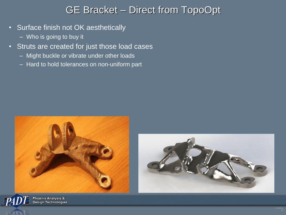
GE Bracket – Direct from TopoOpt
• Surface finish not OK aesthetically
– Who is going to buy it
• Struts are created for just those load cases
– Might buckle or vibrate under other loads
– Hard to hold tolerances on non-uniform part
mm/dd/yy
65
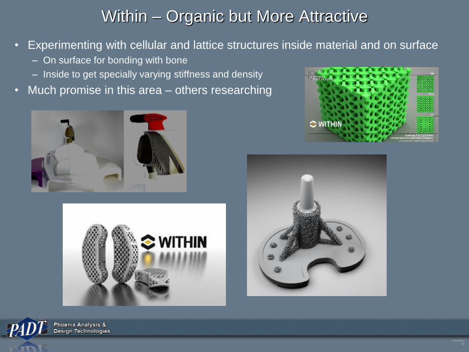
Within – Organic but More Attractive
• Experimenting with cellular and lattice structures inside material and on surface
– On surface for bonding with bone
– Inside to get specially varying stiffness and density
• Much promise in this area – others researching
mm/dd/yy
66
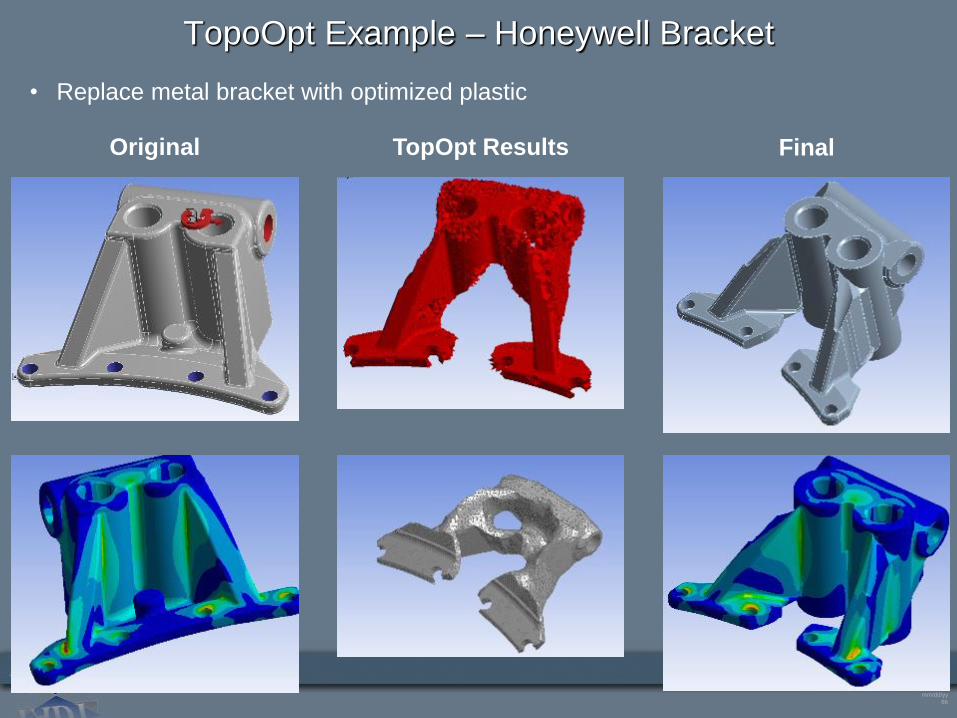
TopoOpt Example – Honeywell Bracket
• Replace metal bracket with optimized plastic
Original TopOpt Results Final
mm/dd/yy
67
Simulation Future
• Working with ANSYS Inc, government, academia, and customers to develop
material models
– For poly, based on some build parameters -> produce isotropic properties
• Streamline the connection between process modelers for metal to solvers
– Get accureate thermal and residual stresses
– Predict stiffness and poison’s ratio based on melt history
• Where to watch
– ANSYS, Inc. publications
– America Makes (Americamakes.us)
– Lawrence Livermore leads in process modeling for metal
– Academia
• ASU is making a move
• UTEP
• Pitt
• NPDRC in Cardiff
• ????
mm/dd/yy
68
What Next?
mm/dd/yy
69
What Does Industry Want?
• High-accuracy, fast converging models for AM processes
• Real time measurement of composition, temperature, cooling rate, dimension, and
distortion leading to the ability to predict dimensions, surface characteristics,
material properties spread, and defects
• Residual stress direction and magnitude
• Integrated multi-scale, multi-physics models from complex to dimensionless
numbers
• Technologies to model design reproducibility for AM
• Repeatable for a minimum feature size
• Modeling to support selection of AM processes based on key standards
• Standards for design specifications
• Standards for Quality
• Fatigue models
mm/dd/yy
70
Where to Learn More
• Get the Wohlers Report Each Year
– http://www.wohlersassociates.com/
– The most complete compendium of what happens each year
• Watch for papers in starting this year and growing
– Search on: Additive Manufacturing Design, Additive Manufacturing Simulation
• Join or watch America Makes
– Major government funding on solving these needs and problems.
• Follow ASTM Standards for Additive Manufacturing
– http://www.astm.org/Standards/additive-manufacturing-technology-standards.html
– Starting to flush out – some powder materials
– Test specimen reporting standard, test process, and test terminology
– Most defined is the terminology: F2792-12a
– Developing replacement for STL - AMF
• More accurate. Contains material, color, texture, and sub-structure info
• Your Vendor
– Get to know them, be their friend, find out who their material testing and process people are
– Offer up some case studies in exchange for info
mm/dd/yy
71
Key Suggestions
• AM parts are different, don’t assume the same methods and process are the best
• Start defining standards and capturing processes
– Document, Document, Document
• Crawl, Walk, Run
– Don’t replace your most critical and important component with an AM part
– Find non-critical parts that you can learn on
• Remember:
– Every machine is different
– Every material is different
– Every build is different
– Ever post-processing is different
• Key features can be machined
• Use big safety factors till you really know the process
• Remember its just a different manufacturing process!
mm/dd/yy
72
Q&A