Embed Size (px)
Citation preview

LunarDREEM Preliminary Design Report
March 10th, 2005
Source: aerospacescholars.jsc.nasa.gov
Jessica Thompson
Presentation Outline ISOP System
Summary of results from Conceptual Design Report Trade Study Electrolysis System Design Oxygen Storage Tank Design Radiator Design Hydrogen Recycling Trade Study Furnace Design Process for Further Design Iterations
Excavation System Summary of Concepts Analysis of Conveyor Belt Concept Analysis of Drill Concept Bulk Physical Measurement Systems Materials Design Considerations
Jessica Thompson
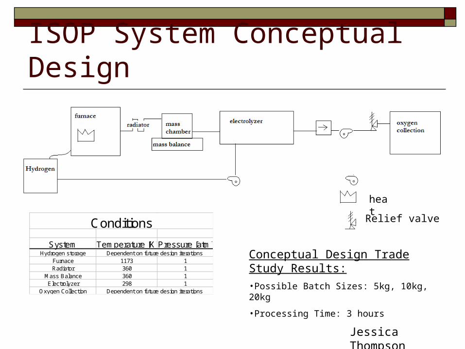
ISOP System Conceptual Design
heat
Relief valve
System Temperature [K]Pressure [atm]Hydrogen storage
Furnace 1173 1Radiator 360 1
Mass Balance 360 1Electrolyzer 298 1
Oxygen Collection
Conditions
Dependent on future design iterations
Dependent on future design iterations
Conceptual Design Trade Study Results:
•Possible Batch Sizes: 5kg, 10kg, 20kg
•Processing Time: 3 hours
Jessica Thompson

Electrolysis System Slides Space Holder
Alice Zhou
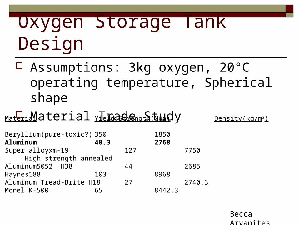
Oxygen Storage Tank Design Assumptions: 3kg oxygen, 20°C operating
temperature, Spherical shape Material Trade Study
Material Yield Strength(Mpa) Density(kg/m3)
Beryllium(pure-toxic?) 350 1850Aluminum 48.3 2768Super alloyxm-19 127 7750 High strength annealedAluminum5052 H38 44 2685Haynes188 103 8968Aluminum Tread-Brite H18 27 2740.3Monel K-500 65 8442.3
Becca Arvanites

Calculating Tank Mass Oxygen Pressure = mass*R*Temp/Volume Radius = [(3/4pi)*Volume]1/3
Tank wall width = Pressure*Radius/Max yield stress Tank mass=Density*Surface area*Width
=Density*4pi*Radius2*WidthMaterial Tank Mass(kg)
Beryllium(pure-toxic?) 36.2Aluminum 39.4Super alloyxm-19 41.8 High strength annealedAluminum5052 H38 41.9Haynes188 59.8Aluminum Tread-Brite H18 69.7Monel K-500 89.2 Becca Arvanites
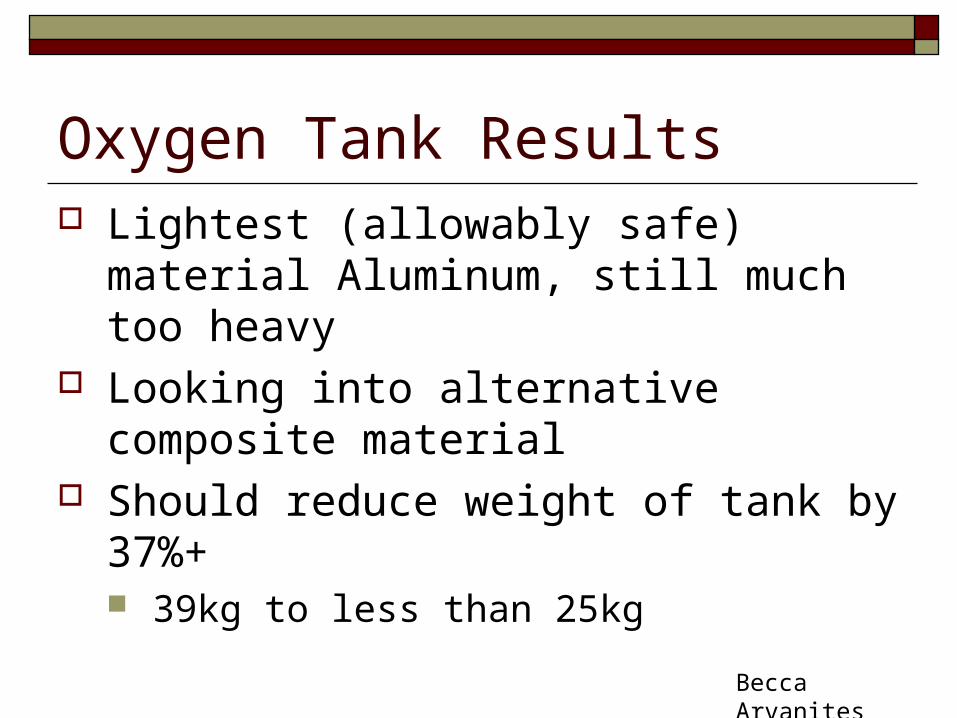
Oxygen Tank Results Lightest (allowably safe) material Aluminum,
still much too heavy Looking into alternative composite material Should reduce weight of tank by 37%+
39kg to less than 25kg
Becca Arvanites
Radiator Study Purpose
To find a suitable length and mass for a radiator to condense Heated Water Vapor (900oC) to Condense Water Vapor (95oC)
Assumptions Total incoming flow value, min will be .002 kg/s
The heat that is released by the water vapor is conducted by aluminum and emitted to space, thus we will calculate the power emitted to space per unit area exposed to the surroundings.
Temperature of the surroundings will be 40 K Efficiency of the radiator will be around 90%
James North
Radiator Study First, the thickness of the aluminum must be found since we
know that the heat generated by radiation should be equal to the heat generated by conduction.
The aluminum tubing will be cover with Multi Layered Insulation which will allow for the use of MLI’s thermal conductivity to be used to find the thickness.
Thickness = -K∙( Tsurroundings - Twater)/[ε∙σ∙(Twater4 – Tsurroundings
4 )]
Thickness = 1.055 x 10⁻⁵ m
James North

Radiator Study Calculations
Iteration process of ΔT = 1 as T > 95oC (368 K)
Power/Area = ε∙σ∙(Twater4 – Tsurroundings
4 )
Cp=143.05 - 183.54∙(T/100).25 + 82.751∙(T/100).5 - 3.6989∙(T/100)
Length=[min∙Cp*(T - ΔT )] /[η∙2∙π∙router∙(Power/Area)]
Mass=ρ*π*(router 2-rinner
2)∙Length
James North
Radiator Study
0 200 400 600 800 1000 12000
0.02
0.04
0.06
0.08
0.1
0.12
0.14
0.16
0.18
Temperature [K]
Leng
th [
m]
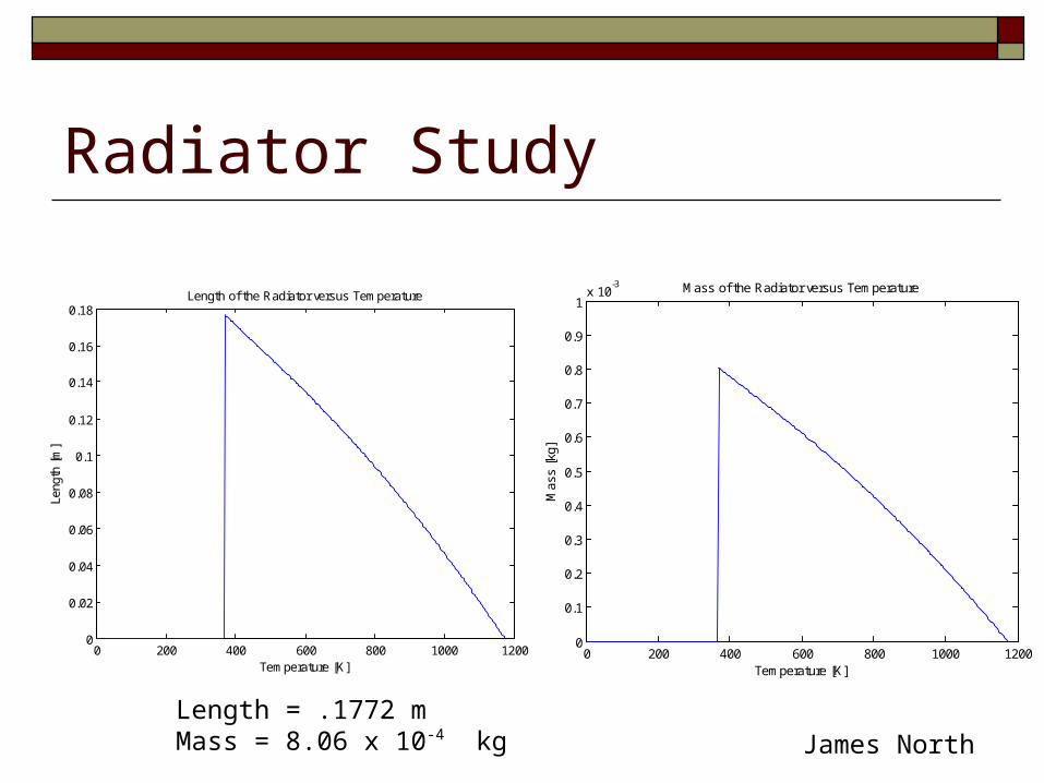
Length of the Radiator versus Temperature
0 200 400 600 800 1000 12000
0.1
0.2
0.3
0.4
0.5
0.6
0.7
0.8
0.9
1x 10
-3
Temperature [K]
Mas
s [k
g]
Mass of the Radiator versus Temperature
Length = .1772 m Mass = 8.06 x 10-
4 kg James North
Radiator Study Must taken into consideration lunar regolith covering the
MLI during operations Assume the efficiency of the radiator to drop to 80% Outside regolith may adversely affect the temperature of condensed
water vapor exiting the radiator Very important to not have that temperature bet 0oC
James North
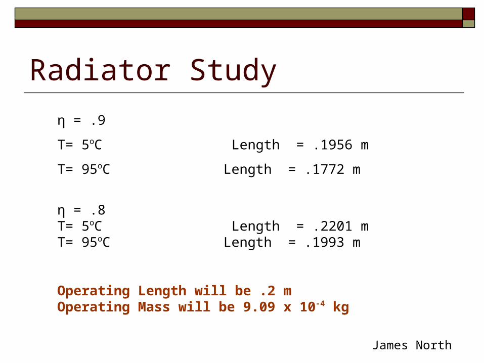
Radiator Study
η = .9
T= 5oC Length = .1956 m
T= 95oC Length = .1772 m
η = .8T= 5oC Length = .2201 mT= 95oC Length = .1993 m
Operating Length will be .2 mOperating Mass will be 9.09 x 10⁻⁴ kg
James North
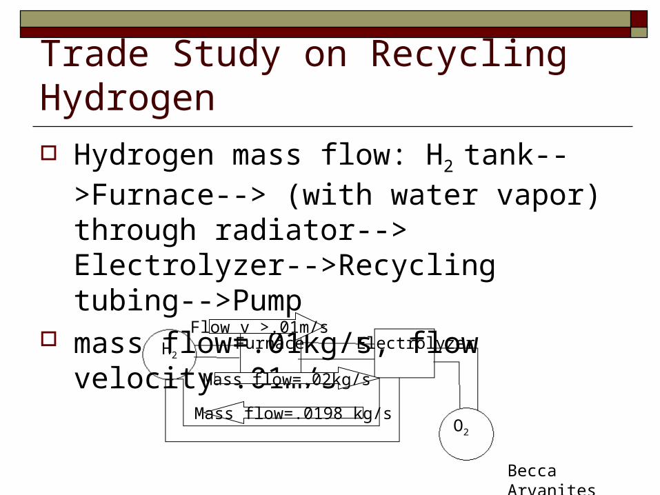
Trade Study on Recycling Hydrogen Hydrogen mass flow: H2
tank-->Furnace--> (with water vapor) through radiator--> Electrolyzer-->Recycling tubing-->Pump
mass flow=.01kg/s, flow velocity=.01m/s
H2
O2
Furnace Electrolyzer
Mass flow=.02kg/s
Mass flow=.0198 kg/s
Flow v >.01m/s
Becca Arvanites
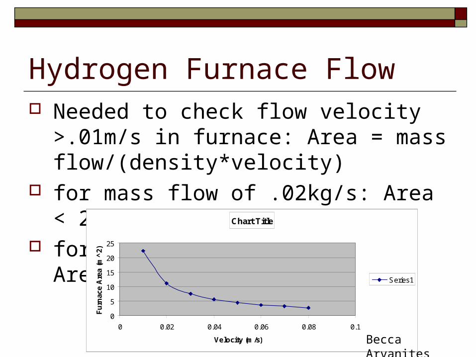
Hydrogen Furnace Flow Needed to check flow velocity >.01m/s in
furnace: Area = mass flow/(density*velocity) for mass flow of .02kg/s: Area < 22m2 for flow velocity = .08m/s: Area=2.78m2
Chart Title
0
5
10
15
20
25
0 0.02 0.04 0.06 0.08 0.1
Velocity (m/s)
Fu
rnac
e A
rea
(m^
2)
Series1
Becca Arvanites
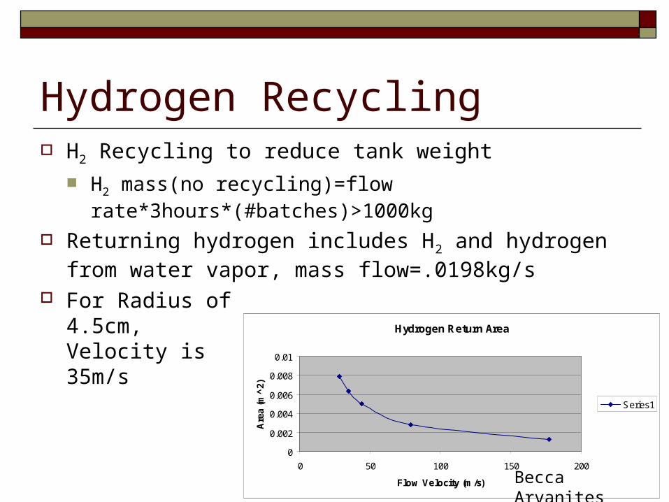
Hydrogen Recycling H2 Recycling to reduce tank weight
H2 mass(no recycling)=flow rate*3hours*(#batches)>1000kg
Returning hydrogen includes H2 and hydrogen from water vapor, mass flow=.0198kg/s
For Radius of4.5cm,Velocity is35m/s
Hydrogen Return Area
0
0.002
0.004
0.006
0.008
0.01
0 50 100 150 200
Flow Velocity (m/s)
Are
a (m
^2)
Series1
Becca Arvanites
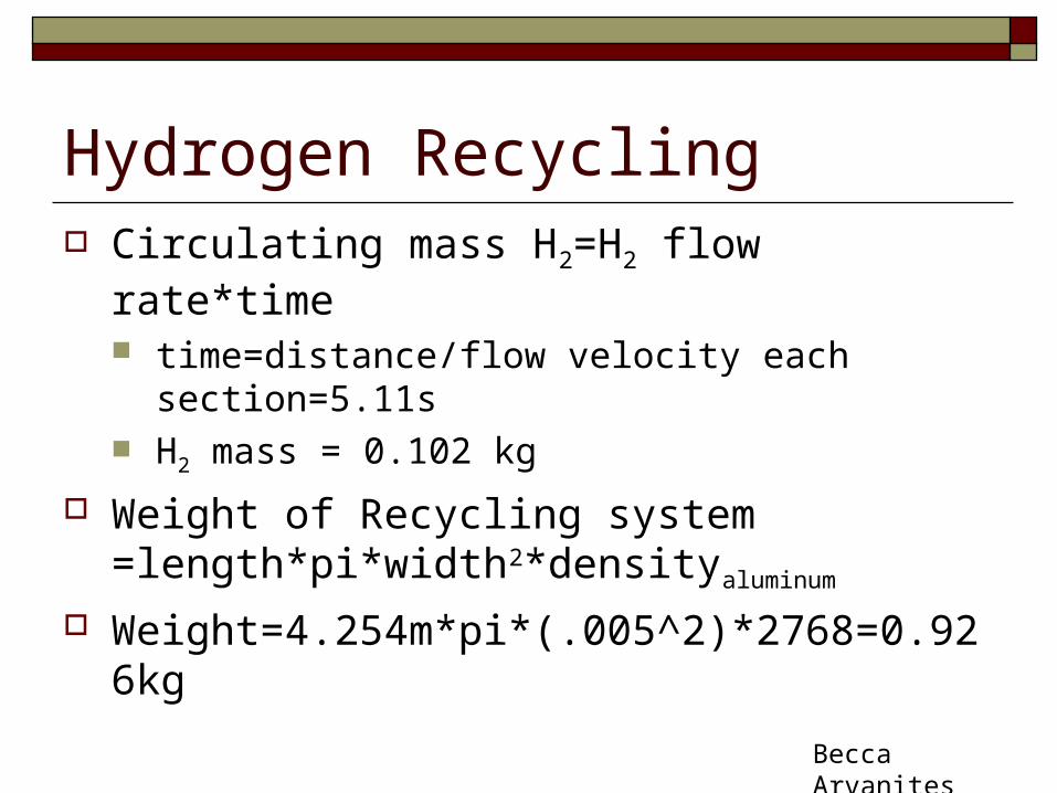
Hydrogen Recycling Circulating mass H2=H2 flow rate*time
time=distance/flow velocity each section=5.11s H2 mass = 0.102 kg
Weight of Recycling system =length*pi*width2*densityaluminum
Weight=4.254m*pi*(.005^2)*2768=0.926kg
Becca Arvanites
Furnace Heating Trade Study: Heating Method
Electrical Resistance Furnace
Microwave Furnace
RHU Technology Based Furnace
JoHanna P.

Furnace Heating Trade Study: SummaryFurnace Design Type
Electrical Microwave RHU
Pros: - Ability to adjust heat output (i.e. to reach and maintain a constant temp)
- Ability to adjust heat output (i.e. to reach and maintain a constant temp)- More even distribution of regolith heating than electrical furnaces- More efficient than electrical furnaces
- Heating units are very light
- Requires no power from the rover or lander
- RHUs are space proven technologies
- Design can be specific for this application
Cons: - Currently poor estimate for sizing and power requirements
- No method for better estimation in the foreseeable future
- Not designed for space and never used in space
- Currently no information on sizing and power requirements
- No method for better estimation in the foreseeable future
- Not designed for space and never used in space
- Continuously outputting heat
- Must design furnace from scratch
- Potential for this to not be feasible
JoHanna P.
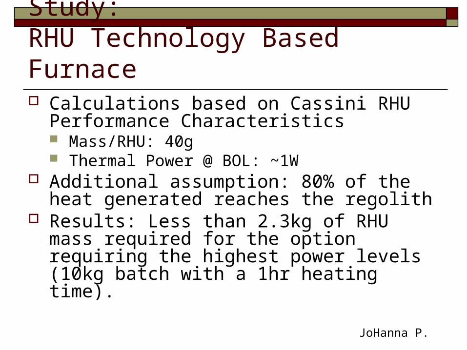
Furnace Heating Trade Study: RHU Technology Based Furnace Calculations based on Cassini RHU
Performance Characteristics Mass/RHU: 40g Thermal Power @ BOL: ~1W
Additional assumption: 80% of the heat generated reaches the regolith
Results: Less than 2.3kg of RHU mass required for the option requiring the highest power levels (10kg batch with a 1hr heating time).
JoHanna P.
RHUs will continuously output heat; thus, heating the inside of the furnace after the regolith has reached the desired temperature.
RHUs will radiate heat in all directions. RHU geometric distribution around the regolith will
impact regolith temperature distribution. Regolith heating characteristics will impact regolith
temperature distribution.
Furnace Heating Trade Study: RHU Technology Based Furnace Design Considerations
JoHanna P.
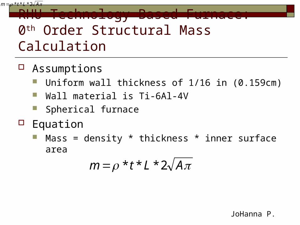
RHU Technology Based Furnace: 0th Order Structural Mass Calculation
Assumptions Uniform wall thickness of 1/16 in (0.159cm) Wall material is Ti-6Al-4V Spherical furnace
Equation Mass = density * thickness * inner surface area
ALtm 2***
ALtm 2***
JoHanna P.

Place Holder for Parametrics Furnace Mass Curve
JoHanna P.

ISOPS Design Flow Chart
Radiator – mass flow rate (kg/s)
Hydrogen gas flow requirement (Allen and McKay)
Batch Size in Furnace
Furnace hydrogen mass flow (kg/s)
Furnace Cross-sectional Area
Hydrogen-recycling trade-study
Electrolyzer Design
Oxygen Tank Design
Given: Design Calculations Yield:
*What we have shown today is the first iteration through this design process
JoHanna P.

Presentation Outline ISOP System
Summary of results from Conceptual Design Report Trade Study Electrolysis System Design Oxygen Storage Tank Design Radiator Design Hydrogen Recycling Trade Study Furnace Design Process for Further Design Iterations
Excavation System Summary of Concepts Analysis of Conveyor Belt Concept Analysis of Drill Concept Bulk Physical Measurement Systems Materials Design Considerations
Jason Atkins
Excavation System Includes:
Excavator Subsystem to collect regolith Bulk Physical Characteristics Test Chamber Delivery System to transfer regolith from Excavator
Subsystem to ISOPS We discuss preliminary designs for the Excavator
Subsystem and Bulk Physical Characteristics Test Chamber Shape and orientation of Bulk Physical Characteristics
Test Chamber constrain choice of Delivery System
Jason Atkins
Excavator Subsystem Concepts Conceptual Design Trade Study identified
two promising concepts: Conveyor Belt Drill
Jason Atkins
Place Holder for Conveyor Belt Slides
Jason Atkins

Drilling: Power Considerations
Constraints: Drill depth at least 1 meter
deep. 100 kg of Lunar Regolith
must be collected. Maximum Power Usage=
100 W
Emmanuel Sin

Drilling Strategy The Drill will have a
cutting edge that will allow it to cut into the Lunar Regolith.
As the Drill moves downward, soil will travel up through the flights.
“Peck-drilling” will prevent the flights from filling up with soil and thus prevent the Drill from getting stuck.
Emmanuel Sin
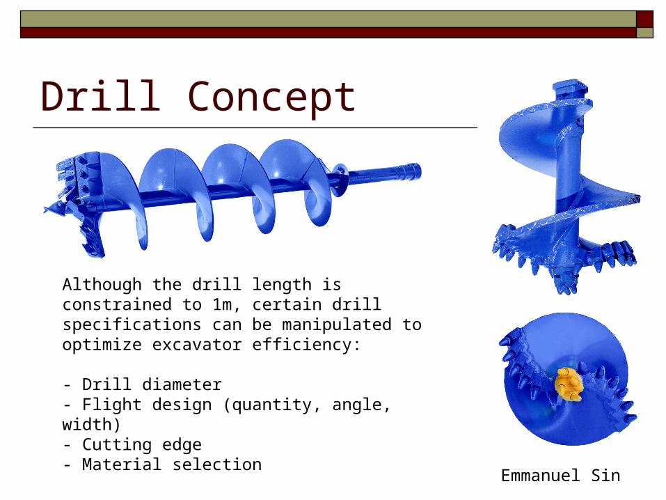
Drill Concept
Although the drill length is constrained to 1m, certain drill specifications can be manipulated to optimize excavator efficiency:
- Drill diameter- Flight design (quantity, angle, width)- Cutting edge- Material selection
Emmanuel Sin

Drill: Power Calculations P= F*V P= T*W
Requires experimental data!
Emmanuel Sin
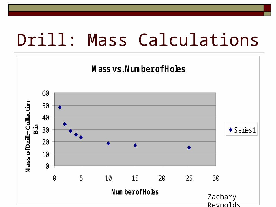
Mass vs. Number of Holes
0
10
20
30
40
50
60
0 5 10 15 20 25 30
Number of Holes
Mas
s of
Dril
l + C
olle
ctio
n B
in Series1
Drill: Mass Calculations
Zachary Reynolds
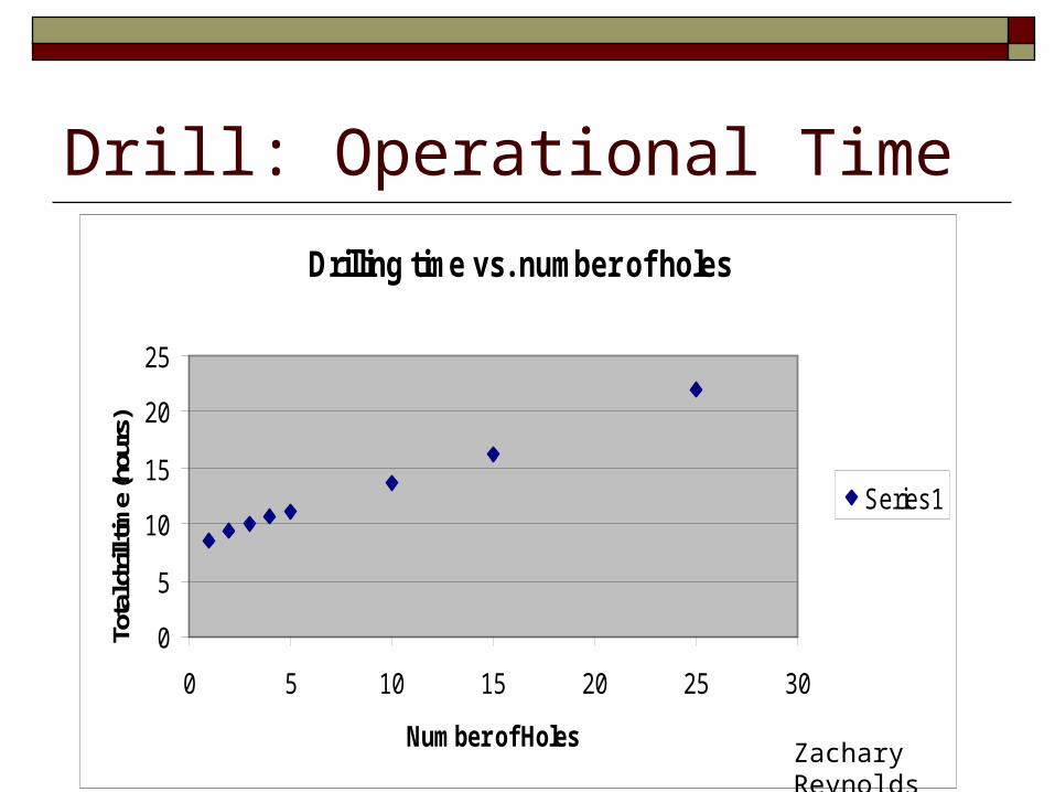
Drill: Operational Time
Drilling time vs. number of holes
0
5
10
15
20
25
0 5 10 15 20 25 30
Number of Holes
Tota
l dril
l tim
e (h
ours
)
Series1
Zachary Reynolds
Calculations Number of holes to drill-> radius of each hole
-> torque required to drill hole of this radius-> necessary inner radius of drill to bear such a torque -> mass of drill
Assume torque required is proportional to cube of radius of hole
Assume 100W motor ~2 kg (http://scootersupport.com/motors.htm)
Zachary Reynolds

Electra Lazer DP SpecificationsTwin Serrated Stainless Steel Lazer
Blades 12 Volt Battery Pack
12 Volt Battery Charger External Battery Cables
190-200 RPM Cutting Speed 20 Amp Draw
Optional extensions available for cutting through ice thicker than 42“
Electra Lazer 12000 DP 5" 26 Lbs. Electra Lazer 12000 DP 6" 27 Lbs. Electra Lazer 12000 DP 7" 28 Lbs. Electra Lazer 12000 DP 8" 29 Lbs.
Source:
http://www.strikemaster.com/electra.html
Commercially Available Ice Auger
Zachary Reynolds

Bulk Physical Measurement Systems Three Concepts:
Compression Chamber Rotary Bar Pin Pull
Jordan Medeiros

Compression ChamberShear Compartment
Compressive Piston
Shear Line
Shear Piston
Mode of Operation:• Sample is loaded into the chamber and compressed to a desired
displacement by the compressive piston. The force required to reach such a displacement is backed out by taking the voltage applied by the actuator to the piston.
• A voltage is then applied to the second actuator controlling the shear piston. This voltage is slowly increased until a displacement occurs along the shear line. This voltage represents the force required to yield the material.
• Using a set of such measurements, we can construct a stress-strain curve for the material and back out other physical characteristics as well.
Jordan Medeiros
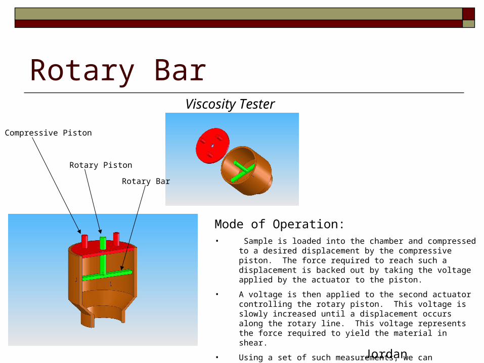
Rotary BarViscosity Tester
Compressive Piston
Rotary Bar
Rotary Piston
Mode of Operation:• Sample is loaded into the chamber and compressed to a desired
displacement by the compressive piston. The force required to reach such a displacement is backed out by taking the voltage applied by the actuator to the piston.
• A voltage is then applied to the second actuator controlling the rotary piston. This voltage is slowly increased until a displacement occurs along the rotary line. This voltage represents the force required to yield the material in shear.
• Using a set of such measurements, we can construct a stress-strain curve for the material and back out other physical characteristics as well.
Jordan Medeiros
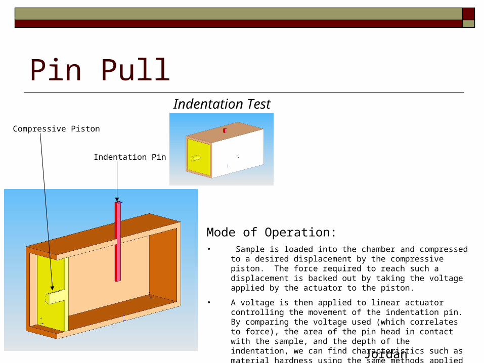
Pin PullIndentation Test
Compressive Piston
Indentation Pin
Mode of Operation:• Sample is loaded into the chamber and compressed to a desired
displacement by the compressive piston. The force required to reach such a displacement is backed out by taking the voltage applied by the actuator to the piston.
• A voltage is then applied to linear actuator controlling the movement of the indentation pin. By comparing the voltage used (which correlates to force), the area of the pin head in contact with the sample, and the depth of the indentation, we can find characteristics such as material hardness using the same methods applied in nano-indentation applications.
Jordan Medeiros
Bulk Physical Measurement Systems
Pros All the systems require very few moving parts, significantly lowering the chance of failure All the systems require very few sensors to back out the required data All the systems work in any scale, allowing for flexibility in design
Cons Both the viscosity tester and indentation system are prone to a problem known as frame compliance – the frame of
the testing unit, being of finite stiffness, undergoes a displacement when placed in a state of stress. This must be accounted for by calibrating the test unit.
Since it is not known what is the required force to shear the material it is difficult to determine certain design factors – The power of the motors driving the pistons, the required frame material stiffness, etc.
These systems do not get direct measurements of the desired characteristics – these must be found using raw data and calculation software.
Jordan Medeiros
Other Considerations: Bulk Physical Measurement Systems Primary factors Affecting physical properties
of lunar regolith: Particle structure and distribution Bulk density and porosity Relative density
Etienne Toussaint

Other Considerations: Bulk Physical Measurement Systems Particle structure and distribution
Variable that controls to various degrees the strength and compressibility of the material
The structure and void ratio of the particles can be altered through the excavation process While in the test chamber, the particle structure will directly
impact the relative density of the regolith and how easy it to compress it or conduct the rotary tests
All concepts will alter the particle structure during the compression test, which may make it harder to conduct the test for shear force using the rotary bar and wire pull
Etienne Toussaint
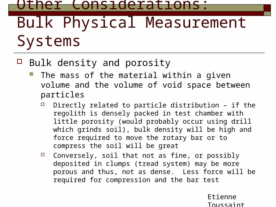
Other Considerations: Bulk Physical Measurement Systems Bulk density and porosity
The mass of the material within a given volume and the volume of void space between particles Directly related to particle distribution – if the regolith is densely
packed in test chamber with little porosity (would probably occur using drill which grinds soil), bulk density will be high and force required to move the rotary bar or to compress the soil will be great
Conversely, soil that not as fine, or possibly deposited in clumps (tread system) may be more porous and thus, not as dense. Less force will be required for compression and the bar test
Etienne Toussaint
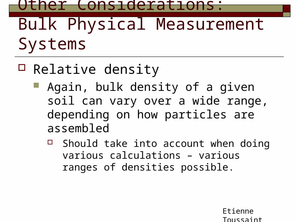
Other Considerations: Bulk Physical Measurement Systems Relative density
Again, bulk density of a given soil can vary over a wide range, depending on how particles are assembled Should take into account when doing various
calculations – various ranges of densities possible.
Etienne Toussaint
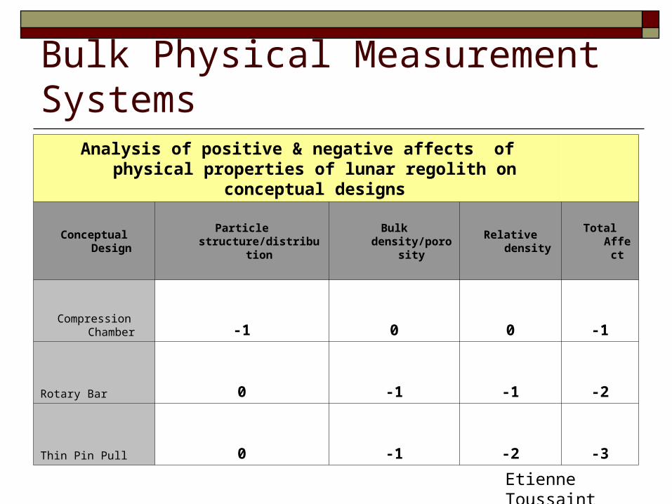
Bulk Physical Measurement SystemsAnalysis of positive & negative affects of physical properties of
lunar regolith on conceptual designs
Conceptual Design Particle structure/distribution Bulk density/porosity Relative density Total Affect
Compression Chamber -1 0 0 -1
Rotary Bar 0 -1 -1 -2
Thin Pin Pull 0 -1 -2 -3
Etienne Toussaint
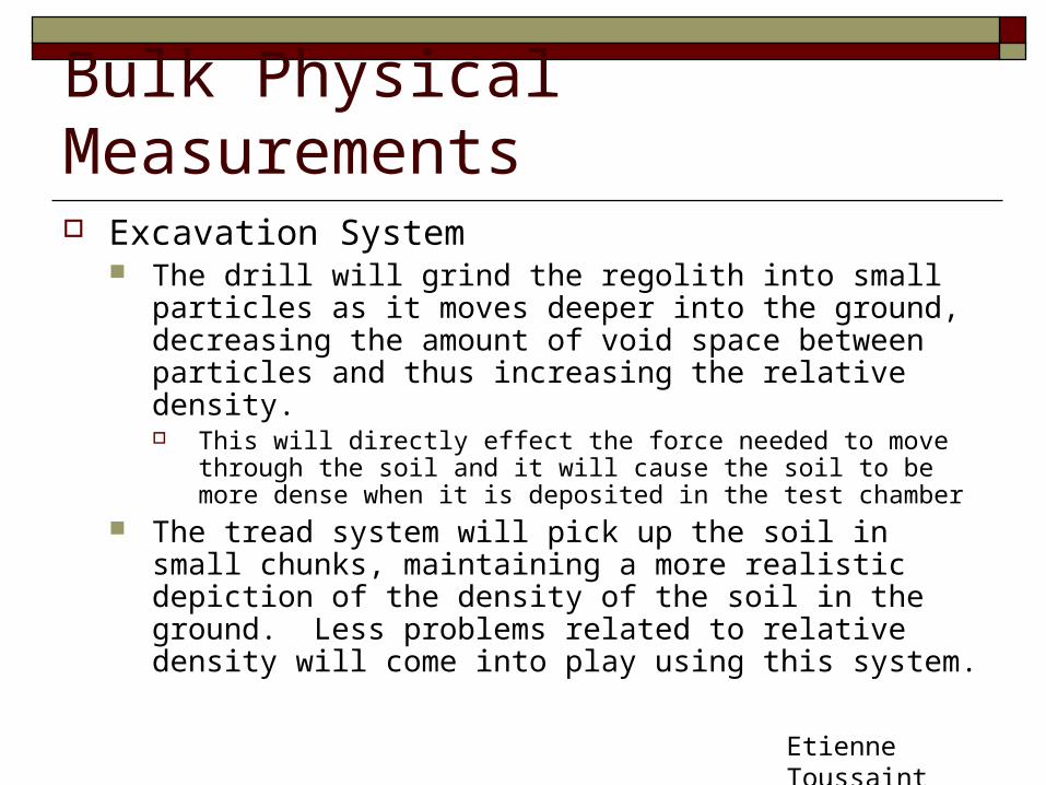
Bulk Physical Measurements Excavation System
The drill will grind the regolith into small particles as it moves deeper into the ground, decreasing the amount of void space between particles and thus increasing the relative density. This will directly effect the force needed to move through the
soil and it will cause the soil to be more dense when it is deposited in the test chamber
The tread system will pick up the soil in small chunks, maintaining a more realistic depiction of the density of the soil in the ground. Less problems related to relative density will come into play using this system.
Etienne Toussaint
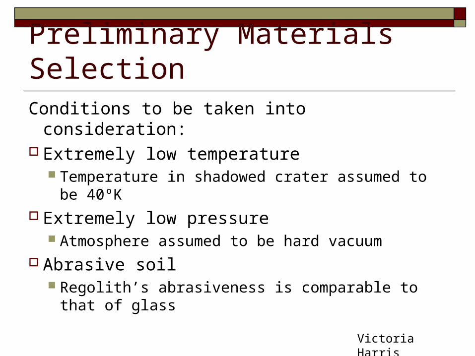
Preliminary Materials SelectionConditions to be taken into consideration: Extremely low temperature
Temperature in shadowed crater assumed to be 40ºK Extremely low pressure
Atmosphere assumed to be hard vacuum Abrasive soil
Regolith’s abrasiveness is comparable to that of glass
Victoria Harris

Preliminary Materials SelectionLubricants1
Choose interfacing materials that have different crystal structures and atomic sizes
Wet lubrication Oils will most likely not work in low temperatures
Dry lubrication Some work in low temperatures (eg molybdenum
disulfide) Shorter service life
Victoria Harris

Preliminary Materials SelectionMetals2
Most metals will work E.g. stainless steels, aluminum alloys Exceptions include nickel steels
Some material properties will change at low temperature E.g. coefficient of friction
Composites are also a possibility
Victoria Harris

Preliminary Materials SelectionInsulation/rubber Rubber suitable for constructing a conveyor
belt will not withstand low temperatures3
Other belt designs must be investigated Typical insulators used in cryogenic
applications can be applied E.g. ethylene-propylene4
Victoria Harris
Bibliography1. Virgil R. Friebel and James T. Hinricks. “Lubrication for
vacuum applications.” Journal of Vacuum Science and Technology. January 1975. Volume 12, Issue 1, pp. 551-554.
2. JG Weisend, ed. Handbook of Cryogenic Engineering. Hamburg, Germany: Taylor and Francis, 1998.
3. www.mcmaster.com4. Atsushi Minoda and Yasuichi Mitsuyama. “AC Treeing of
Ethylene-Propylene Rubber in Cryogenic Temperature Region.” Electrical Engineering in Japan, Vol. 124, No. 3, 1998.
Victoria Harris

Outreach Update
Julie Arnold

Ordering Laboratory Materials
Julie Arnold


![[SIZE MATTERS] - CORE · 2016. 8. 11. · Archaeology Honours JORDAN TOWERS Supervised by Dr Jessica Thompson Title Image: Unidentifiable Fragments from Bushrangers Cave H92, excavation](https://img.pdfslide.us/doc/110x75/6035d7706b63bf191551092a/size-matters-core-2016-8-11-archaeology-honours-jordan-towers-supervised.jpg)