Embed Size (px)
Citation preview
431-ICD-000085 Revision B DraftA Effective Date: July 17, 2006
Expiration Date: July 17, 2011
CHECK WITH LRO DATABASE AT: https://lunarngin.gsfc.nasa.gov
TO VERIFY THAT THIS IS THE CORRECT VERSION PRIOR TO USE.
Lunar Reconnaissance Orbiter Project
Cosmic Ray Telescope for the Effects of Radiation to Spacecraft Mechanical Interface Control Document
Goddard Space Flight Center Greenbelt, Maryland
National Aeronautics and Space Administration
CRaTER to Spacecraft Mechanical ICD 431-ICD-000085 Revision A
CHECK WITH LRO DATABASE AT: https://lunarngin.gsfc.nasa.gov
TO VERIFY THAT THIS IS THE CORRECT VERSION PRIOR TO USE.
CM FOREWORD
This document is a Lunar Reconnaissance Orbiter (LRO) Project Configuration Management (CM)-controlled document. Changes to this document require prior approval of the applicable Configuration Control Board (CCB) Chairperson or designee. Proposed changes shall be submitted to the LRO CM Office (CMO), along with supportive material justifying the proposed change. Changes to this document will be made by complete revision. Questions or comments concerning this document should be addressed to: LRO Configuration Management Office Mail Stop 431 Goddard Space Flight Center Greenbelt, Maryland 20771
CRaTER to Spacecraft Mechanical ICD 431-ICD-000085 Revision A
CHECK WITH LRO DATABASE AT: https://lunarngin.gsfc.nasa.gov
TO VERIFY THAT THIS IS THE CORRECT VERSION PRIOR TO USE
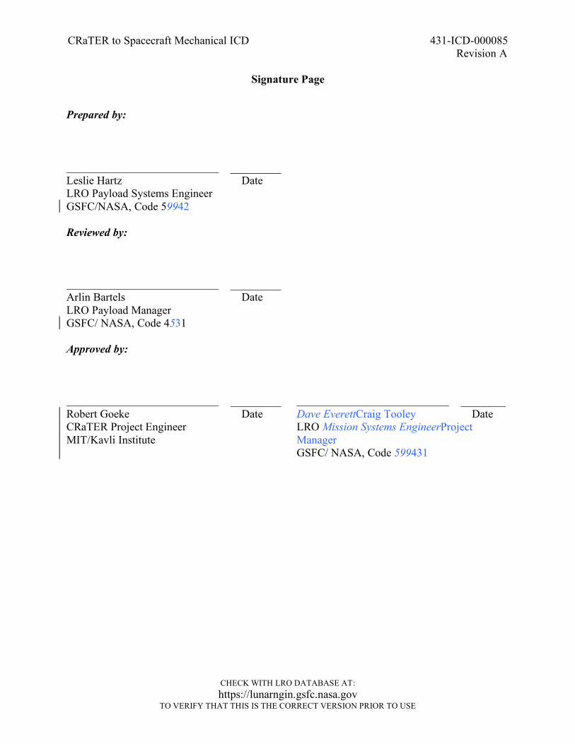
Signature Page
Prepared by: _________ Leslie Hartz Date LRO Payload Systems Engineer GSFC/NASA, Code 59942
Reviewed by:
_________ Arlin Bartels Date LRO Payload Manager GSFC/ NASA, Code 4531
Approved by:
_________ Robert Goeke Date CRaTER Project Engineer MIT/Kavli Institute
________ Dave EverettCraig Tooley Date LRO Mission Systems EngineerProject Manager GSFC/ NASA, Code 599431
CRaTER to Spacecraft Mechanical ICD 431-ICD-000085 Revision A
CHECK WITH LRO DATABASE AT: https://lunarngin.gsfc.nasa.gov
TO VERIFY THAT THIS IS THE CORRECT VERSION PRIOR TO USE
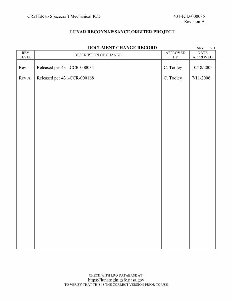
LUNAR RECONNAISSANCE ORBITER PROJECT
DOCUMENT CHANGE RECORD Sheet: 1 of 1 REV
LEVEL DESCRIPTION OF CHANGE APPROVED BY
DATE APPROVED
Rev- Rev A
Released per 431-CCR-000034 Released per 431-CCR-000168
C. Tooley C. Tooley
10/18/2005 7/11/2006
CRaTER to Spacecraft Mechanical ICD 431-ICD-000085 Revision A
CHECK WITH LRO DATABASE AT: https://lunarngin.gsfc.nasa.gov
TO VERIFY THAT THIS IS THE CORRECT VERSION PRIOR TO USE
List of TBDs/TBRs
Item No.
Location Summary Ind./Org. Due Date
CRaTER to Spacecraft Mechanical ICD 431-ICD-000085 Revision A
ii
CHECK WITH LRO DATABASE AT: https://lunarngin.gsfc.nasa.gov
TO VERIFY THAT THIS IS THE CORRECT VERSION PRIOR TO USE.
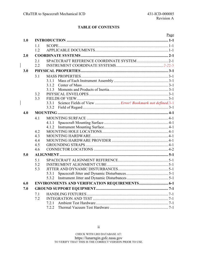
TABLE OF CONTENTS
Page 1.0 INTRODUCTION ..................................................................................................... 1-1
1.1 SCOPE............................................................................................................. 1-1 1.2 APPLICABLE DOCUMENTS......................................................................... 1-1
2.0 COORDINATE SYSTEMS....................................................................................... 2-1 2.1 SPACECRAFT REFERENCE COORDINATE SYSTEM ............................... 2-1 2.2 INSTRUMENT COORDINATE SYSTEMS...............................................2-22-3
3.0 PHYSICAL PROPERTIES....................................................................................... 3-1 3.1 MASS PROPERTIES....................................................................................... 3-1
3.1.1 Mass of Each Instrument Assembly ...................................................... 3-1 3.1.2 Center of Mass...................................................................................... 3-1 3.1.3 Moments and Products of Inertia........................................................... 3-1
3.2 PHYSICAL ENVELOPES............................................................................... 3-1 3.3 FIELDS OF VIEW........................................................................................... 3-1
3.3.1 Science Fields of View ......................... Error! Bookmark not defined.3-1 3.3.2 Field of Regard ..................................................................................... 3-1
4.0 MOUNTING .............................................................................................................. 4-1 4.1 MOUNTING SURFACE ................................................................................. 4-1
4.1.1 Spacecraft Mounting Surface ................................................................ 4-1 4.1.2 Instrument Mounting Surface................................................................ 4-1
4.2 MOUNTING HOLE LOCATIONS.................................................................. 4-1 4.3 MOUNTING HARDWARE............................................................................. 4-1 4.4 MOUNTING HARDWARE PROVIDER ........................................................ 4-1 4.5 GROUNDING STRAPS .................................................................................. 4-1 4.6 CONNECTOR LOCATIONS .......................................................................... 4-2
5.0 ALIGNMENT ............................................................................................................ 5-1 5.1 SPACECRAFT ALIGNMENT REFERENCE.................................................. 5-1 5.2 INSTRUMENT ALIGNMENT CUBE............................................................. 5-1 5.3 JITTER AND DYNAMIC DISTURBANCES.................................................. 5-1
5.3.1 Spacecraft Jitter and Dynamic Disturbances.......................................... 5-1 5.3.2 Instrument Jitter and Dynamic Disturbances ......................................... 5-1
6.0 ENVIRONMENTS AND VERIFICATION REQUIREMENTS............................. 6-1 7.0 GROUND SUPPORT EQUIPMENT........................................................................ 7-1
7.1 HANDLING FIXTURES................................................................................. 7-1 7.2 INTEGRATION AND TEST ........................................................................... 7-1
7.2.1 Ambient Test Hardware........................................................................ 7-1 7.2.2 Thermal Vacuum Test Hardware .......................................................... 7-1
CRaTER to Spacecraft Mechanical ICD 431-ICD-000085 Revision A
iii
CHECK WITH LRO DATABASE AT: https://lunarngin.gsfc.nasa.gov
TO VERIFY THAT THIS IS THE CORRECT VERSION PRIOR TO USE.
TABLE OF CONTENTS (CONTINUED)
Page 8.0 LAUNCH VEHICLE CONSIDERATIONS............................................................. 8-1
8.1 ACCESSS IN LAUNCH VEHICLE FAIRING................................................ 8-1 8.2 RED TAG ITEMS............................................................................................ 8-1 8.3 GREEN TAG ITEMS....................................................................................... 8-1
9.0 CONTAMINATION/ PURGE REQUIREMENTS.................................................. 9-1 9.1 CONTAMINATION CONTROL PLAN.......................................................... 9-1 9.2 PURGE ............................................................................................................ 9-1
9.2.1 Purge Port Location and Access............................................................ 9-1 9.2.2 Other Contamination Considerations..................................................... 9-1
10.0 MODEL REQUIREMENTS ................................................................................... 10-1 10.1 COMPUTER AIDED DESIGN (CAD) MODEL REQUIREMENTS............. 10-1 10.2 FINITE ELEMENT MODEL REQUIREMENTS .......................................... 10-1 10.3 MASS SIMULATORS................................................................................... 10-1
Appendix A. Abbreviations and Acronyms........................................................................ A-1
LIST OF FIGURES Figure Page Figure 2-1. LRO Reference Coordinate System .................................................................2-12-3
CRaTER to Spacecraft Mechanical ICD 431-ICD-000085 Revision A
1-1
CHECK WITH LRO DATABASE AT: https://lunarngin.gsfc.nasa.gov
TO VERIFY THAT THIS IS THE CORRECT VERSION PRIOR TO USE.
1.0 INTRODUCTION
The Lunar Reconnaissance Orbiter (LRO) is the first mission of the Robotic Lunar Exploration Program (RLEP). The LRO mission is focused on obtaining new data that will facilitate returning humans safely to the moon. This mission will launch late in 2008 and will take measurements of the moon for at least one year. The LRO spacecraft is made up of several modules. The propulsion module interfaces to the launch vehicle and houses the propulsion system. The avionics module houses most of the electronics equipment to run the spacecraft. At the top of the spacecraft is the instrument module where LRO’s six instruments are located. LRO also has two deployable components, a solar array and a high gain antenna. LRO has six instruments to perform its exploration measurements. They are Cosmic Ray Telescope for the Effects of Radiation (CRaTER), Diviner Lunar Radiometer Experiment (DLRE), Lyman-Alpha Mapping Project (LAMP), Lunar Exploration Neutron Detector (LEND), Lunar Orbiter Laser Altimeter (LOLA) and the Lunar Reconnaissance Orbiter Camera (LROC). The CRaTER will characterize the global lunar radiation environment and its biological impacts. CRaTER will focus on radiation above the 10 Mega-electron Volt (MeV) range. CRaTER employs a stack of detectors embedded within aluminum structure and tissue-equivalent plastic to establish the linear energy transfer of cosmic radiation relevant for human and electronic parts considerations. 1.1 SCOPE
The purpose of this document is to establish the unique mechanical interfaces between the Lunar Reconnaissance Orbiter and CRaTER.
1.2 APPLICABLE DOCUMENTS
431-PLAN-000110 Lunar Reconnaissance Orbiter Contamination Control Plan 431-RQMT-000112 Lunar Reconnaissance Orbiter Technical Resource Allocations 431-SPEC-000008 Lunar Reconnaissance Orbiter Electrical Systems Specification 431-SPEC-000012 Lunar Reconnaissance Orbiter Mechanical Systems Specification 431-SPEC-000113 Lunar Reconnaissance Orbiter Pointing and Alignment
Specification 32-01203 Cosmic Ray Telescope for the Effects of Radiation Contamination
Control Plan 32-02003.02 Cosmic Ray Telescope for the Effects of Radiation Mechanical-
Thermal Interface Drawing 2086898 Spacecraft Assembly Drawing
CRaTER to Spacecraft Mechanical ICD 431-ICD-000085 Revision A
2-1
CHECK WITH LRO DATABASE AT: https://lunarngin.gsfc.nasa.gov
TO VERIFY THAT THIS IS THE CORRECT VERSION PRIOR TO USE.
2.0 COORDINATE SYSTEMS
2.1 SPACECRAFT REFERENCE COORDINATE SYSTEM
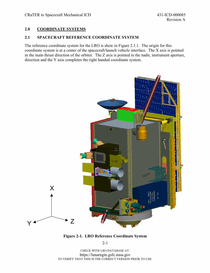
The reference coordinate system for the LRO is show in Figure 2.1.1. The origin for this coordinate system is at a center of the spacecraft/launch vehicle interface. The X axis is pointed in the main thrust direction of the orbiter. The Z axis is pointed in the nadir, instrument aperture, direction and the Y axis completes the right handed coordinate system.
Figure 2-1. LRO Reference Coordinate System
Y
X
Z
CRaTER to Spacecraft Mechanical ICD 431-ICD-000085 Revision A
2-2
CHECK WITH LRO DATABASE AT: https://lunarngin.gsfc.nasa.gov
TO VERIFY THAT THIS IS THE CORRECT VERSION PRIOR TO USE.
2.2 INSTRUMENT COORDINATE SYSTEMS
The reference coordinate system for CRaTER has its origin at the spacecraft to CRaTER interface and its axes are aligned with the spacecraft reference coordinate system. The CRaTER reference system is shown on the CRaTER Mechanical-Thermal Interface Drawing (32-02003.02).
CRaTER to Spacecraft Mechanical ICD 431-ICD-000085 Revision A
3-1
CHECK WITH LRO DATABASE AT: https://lunarngin.gsfc.nasa.gov
TO VERIFY THAT THIS IS THE CORRECT VERSION PRIOR TO USE.
3.0 PHYSICAL PROPERTIES
3.1 MASS PROPERTIES
The mass of the CRaTER instrument shall not exceed its allocation listed in the Lunar Reconnaissance Orbiter Technical Resource Allocations Requirements (431-RQMT-000112). 3.1.1 Mass of Each Instrument Assembly
The CRaTER detector and electronics are all housed within the same assembly. The final as-built mass of the CRaTER Assembly shall be verified by test. 3.1.2 Center of Mass
The center of mass for CRaTER is shown on CRaTER Mechanical-Thermal Interface Drawing (32-02003.02). The final as-built center of mass in each axis shall be calculated.location in the two axes parallel to the mounting plane shall be verified by test. The center of mass location in the axis perpendicular to the mounting plane shall be calculated. 3.1.3 Moments and Products of Inertia
The moments and products of inertia for CRaTER are shown on CRaTER Mechanical-Thermal Interface Drawing (32-02003.02). The final as-built moments and products of inertia for CRaTER shall be calculated. 3.2 PHYSICAL ENVELOPES
CRaTER and its thermal blanket shall remain within the physical envelopeThe physical envelope of CRaTER and its thermal blanket is shown on CRaTER Mechanical-Thermal Interface Drawing (32-02003.02). 3.3 FIELDS OF VIEW
3.3.1 Field of Regard
The CRaTER has two fields of regard, one that points in the nadir direction and one that points in the zenith direction. The nadir facing field of regard is an 80 degree full cone angle and the zenith facing field of view is 35 degree full cone angle. These fields of regard are shown on the CRaTER Mechanical-Thermal Interface Drawing (32-02003.02).
CRaTER to Spacecraft Mechanical ICD 431-ICD-000085 Revision A
4-1
CHECK WITH LRO DATABASE AT: https://lunarngin.gsfc.nasa.gov
TO VERIFY THAT THIS IS THE CORRECT VERSION PRIOR TO USE.
4.0 MOUNTING
CRaTER attaches to the LRO spacecraft through six mounting feet. 4.1 MOUNTING SURFACE
4.1.1 Spacecraft Mounting Surface
The spacecraft mounting surface flatness for CRaTER shall be no greater than 0.005 inches per 12.0 inches. Surface finish requirements are shown on CRaTER Mechanical-Thermal Interface Drawing (32-02003.02). 4.1.2 Instrument Mounting Surface
The mounting surface flatness for CRaTER shall be no greater than 0.005 inches over 12 inches. The mounting surface will have a finish of 32 microinches and plating requirement of MIL-C-5541, Class 2. 4.2 MOUNTING HOLE LOCATIONS
CRaTER shall be mounted to the LRO spacecraft with six fasteners through its feet. The locations of these mounting holes are shown on CRaTER Mechanical-Thermal Interface Drawing (32-02003.02). 4.3 MOUNTING HARDWARE
Standard NAS-1351 shall be used per CRaTER Mechanical-Thermal Interface Drawing (32-02003.02). 4.4 MOUNTING HARDWARE PROVIDER
National Aeronautics and Space Administration (NASA)/Goddard Space Flight Center (GSFC) shall provide all fasteners and washers required to mount CRaTER to the spacecraft. All mounting hardware shall be included in the CRaTER mass allocation. 4.5 GROUNDING STRAPS
The CRaTER instrument shall comply with the grounding requirements in Section 3.2 of the Lunar Reconnaissance Orbiter Electrical Systems Specification (431-SPEC-000008). CRaTER will meet this requirement through its mounting feet. The CRaTER instrument multi-layer insulation (MLI) shall comply with the grounding requirements in Section 3.2 of the Lunar Reconnaissance Orbiter Electrical Systems Specification (431-SPEC-000008). Grounding tabs for the thermal blankets are shown on CRaTER Mechanical-Thermal Interface Drawing (32-02003.02).
CRaTER to Spacecraft Mechanical ICD 431-ICD-000085 Revision A
4-2
CHECK WITH LRO DATABASE AT: https://lunarngin.gsfc.nasa.gov
TO VERIFY THAT THIS IS THE CORRECT VERSION PRIOR TO USE.
4.6 CONNECTOR LOCATIONS
CRaTER has four connectors. Their locations and keep out zones are shown on CRaTER Mechanical-Thermal Interface Drawing (32-02003.02).
CRaTER to Spacecraft Mechanical ICD 431-ICD-000085 Revision A
5-1
CHECK WITH LRO DATABASE AT: https://lunarngin.gsfc.nasa.gov
TO VERIFY THAT THIS IS THE CORRECT VERSION PRIOR TO USE.
5.0 ALIGNMENT
The alignment and pointing requirements for CRaTER are documented in Lunar Reconnaissance Orbiter Pointing and Alignment Specification (431-SPEC-000113). 5.1 SPACECRAFT ALIGNMENT REFERENCE
CRaTER does not need to be aligned to the spacecraft reference. 5.2 INSTRUMENT ALIGNMENT CUBE
CRaTER does not have an alignment cube. 5.3 JITTER AND DYNAMIC DISTURBANCES
5.3.1 Spacecraft Jitter and Dynamic Disturbances
Dynamic disturbances from the spacecraft experienced at the base of CRaTER are documented in the LRO Pointing and Alignment Specification (431-SPEC-000113). 5.3.2 Instrument Jitter and Dynamic Disturbances
CRaTER does not have any moving parts and does not produce any dynamic environments.
CRaTER to Spacecraft Mechanical ICD 431-ICD-000085 Revision A
6-1
CHECK WITH LRO DATABASE AT: https://lunarngin.gsfc.nasa.gov
TO VERIFY THAT THIS IS THE CORRECT VERSION PRIOR TO USE.
6.0 ENVIRONMENTS AND VERIFICATION REQUIREMENTS
All mechanical environments and verification requirements are documented in the Lunar Reconnaissance Orbiter Mechanical Systems Specification (431-SPEC-000012). This document includes requirements for mechanical environments, minimum frequency, factors of safety and test factors.
CRaTER to Spacecraft Mechanical ICD 431-ICD-000085 Revision A
7-1
CHECK WITH LRO DATABASE AT: https://lunarngin.gsfc.nasa.gov
TO VERIFY THAT THIS IS THE CORRECT VERSION PRIOR TO USE.
7.0 GROUND SUPPORT EQUIPMENT
7.1 HANDLING FIXTURES
CRaTER does not require any handling fixtures. 7.2 INTEGRATION AND TEST
7.2.1 Ambient Test Hardware
CRaTER will use a hand held calibration source for ambient testing. No other hardware is required. 7.2.2 Thermal Vacuum Test Hardware
CRaTER does not require any hardware for thermal vacuum testing.
CRaTER to Spacecraft Mechanical ICD 431-ICD-000085 Revision A
8-1
CHECK WITH LRO DATABASE AT: https://lunarngin.gsfc.nasa.gov
TO VERIFY THAT THIS IS THE CORRECT VERSION PRIOR TO USE.
8.0 LAUNCH VEHICLE CONSIDERATIONS
8.1 ACCESSS IN LAUNCH VEHICLE FAIRING
CRaTER does not require access while in the launch vehicle fairing. CRaTER will tie into GN2 purge post fairing installation. The GN2 purge outlet cover must be removed when is hooked up to the the spacecraft purge system. 8.2 RED TAG ITEMS
CRaTER has no red tag, remove before flight, items. 8.3 GREEN TAG ITEMS
CRaTER has no green tag, install before flight, items.
CRaTER to Spacecraft Mechanical ICD 431-ICD-000085 Revision A
9-1
CHECK WITH LRO DATABASE AT: https://lunarngin.gsfc.nasa.gov
TO VERIFY THAT THIS IS THE CORRECT VERSION PRIOR TO USE.
9.0 CONTAMINATION/ PURGE REQUIREMENTS
9.1 CONTAMINATION CONTROL PLAN
The contamination control requirements for CRaTER are documented in the Lunar Reconnaissance Orbiter Contamination Control Plan (431-PLAN-000110) and the CRaTER Contamination Control Plan (32-01203). 9.2 PURGE
9.2.1 Purge Port Location and Access
CRaTER requires a GN2 purge for at least ten minutes per week through out integration and test, and during launch vehicle processing at the Kennedy Space Center (KSC). The location and access for the purge port are shown on CRaTER Mechanical-Thermal Interface Drawing (32-02003.02). 9.2.2 Other Contamination Considerations
CRaTER has no other contamination considerations.
CRaTER to Spacecraft Mechanical ICD 431-ICD-000085 Revision A
10-1
CHECK WITH LRO DATABASE AT: https://lunarngin.gsfc.nasa.gov
TO VERIFY THAT THIS IS THE CORRECT VERSION PRIOR TO USE.
10.0 MODEL REQUIREMENTS
10.1 COMPUTER AIDED DESIGN (CAD) MODEL REQUIREMENTS
CAD models will be delivered to and from CRaTER in Solid Works format. 10.2 FINITE ELEMENT MODEL REQUIREMENTS
The first frequency of CRaTER is over 75 Hertz and does not need to deliver a finite element model to the LRO Project. 10.3 MASS SIMULATORS
The CRaTER program shall deliver a mass simulator that represents the mass and center of mass of CRaTER. The mass of the mass simulator shall be within 5% of the calculated mass of the CRaTER instrument and the center of mass of the mass simulator shall be within +/- 0.5 inches of the calculated mass of the CRaTER instrument. The mounting hole locations on this simulator shall be to the same tolerances as the flight unit. The mass simulator will be used to verify mounting hole locations on the spacecraft.
CRaTER to Spacecraft Mechanical ICD 431-ICD-000085 Revision A
A-1
CHECK WITH LRO DATABASE AT: https://lunarngin.gsfc.nasa.gov
TO VERIFY THAT THIS IS THE CORRECT VERSION PRIOR TO USE
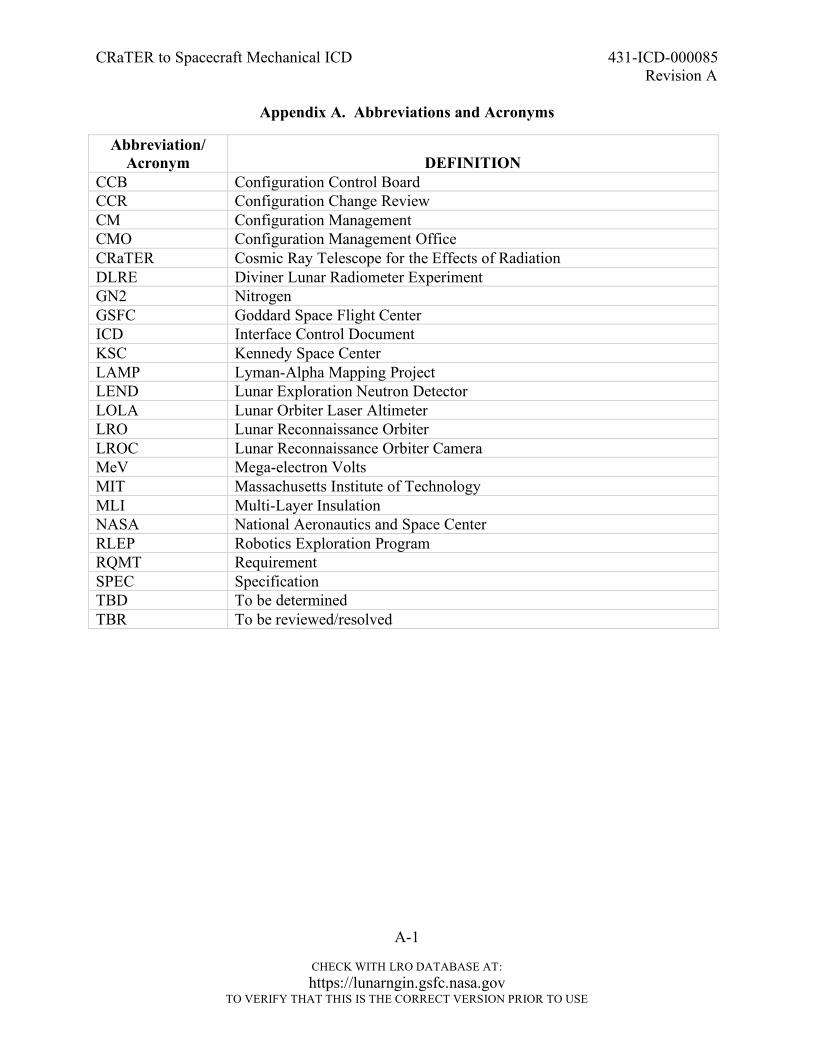
Appendix A. Abbreviations and Acronyms
Abbreviation/ Acronym
DEFINITION
CCB Configuration Control Board CCR Configuration Change Review CM Configuration Management CMO Configuration Management Office CRaTER Cosmic Ray Telescope for the Effects of Radiation DLRE Diviner Lunar Radiometer Experiment GN2 Nitrogen GSFC Goddard Space Flight Center ICD Interface Control Document KSC Kennedy Space Center LAMP Lyman-Alpha Mapping Project LEND Lunar Exploration Neutron Detector LOLA Lunar Orbiter Laser Altimeter LRO Lunar Reconnaissance Orbiter LROC Lunar Reconnaissance Orbiter Camera MeV Mega-electron Volts MIT Massachusetts Institute of Technology MLI Multi-Layer Insulation NASA National Aeronautics and Space Center RLEP Robotics Exploration Program RQMT Requirement SPEC Specification TBD To be determined TBR To be reviewed/resolved