Embed Size (px)
Citation preview
SPECIFICATIONS
HEAT SINK: Die-cast aluminum with external radial fins for natural convection.
ROUGH-IN FRAME: Die-formed aluminum construction. Vertically adjustable collar accommodates ceiling thicknesses up to 2", adjustable post-installation. Universal mounting brackets accept 3/4" and 1-1/2" lathers channel, 1/2" EMT conduit and hanger bars. Quick-access junction box accessible post-installation from above and below ceiling. Includes (4) 1/2" and (2) 3/4" knock-outs to allow straight conduit runs. Listed for (8) 12AWG, 90oC conductors and feed-thru branch wiring. Provided with FMC with electrical quick-connect to Trim Section.
TRIM/HOUSING SECTION: IP-rated housing section incorporates the heat sink, LED module, optics and lower trim. Configurable with an IP64-rated Regressed or Flush lens trim that is secured to the Rough-In frame with hidden torsion springs, and an IP65 Flush lens trim secured with four (4) phillips head, captive fasteners. Anti-microbial finish standard on all exposed painted surfaces. See trim ordering information for available options.
OPTICAL: High-Efficiency mixing chamber design with regressed diffused tempered-glass lens producing uniform light output. Available with various reflector distribution patterns and finishes. Flush lens trim options include a clear lens. See distribution and reflector finish ordering information for available options.
ELECTRICAL: LED array available in multiple CCT and CRI combinations with a maximum 3-step MacAdam variation allowance. See Trim Ordering Information for available options. Luminaire input 24VDC from remote-located, 120-240 VAC, high-power-factor power supply (see MRIPS-312, ordered separately). Standard 0-10V dimming with 1-100% range and dim-to-dark capabilities.
PHOTOMETRICS: Photometry tested to the IESNA LM-79-08 standard by an ILAC/ISO17025 accredited laboratory. For photometric information, go to www.kenall.com.
WARRANTY: One-year SafeScan(TM) guarantee on EMI susceptibility. Five (5) year warranty against mechanical defects. Five (5) year warranty on LED lamps and power regulation components for defects resulting in a fixture lumen depreciation of 30% or greater. Warranty is void if all wiring is not shielded in continuously grounded aluminum conduit.
INSTALLATION: All power and signal wiring must be in completely grounded aluminum conduit. Light engine and internal driver are replaceable post-installation. MRI room EMI filters required (supplied by others).
LISTINGS: Luminaire is certified to UL standards by Intertek Testing Laboratory for IC and Wet Location installations. IP64 and IP65 rating per IEC60598. NSF2 Splash/Non-Food Zone.
Trim StyleR Regressed Lens (IP64)NF Flush Lens (Without Fasteners - IP64)FF Flush Lens (With Fasteners - IP65)
Trim FinishDCFW Die-Cast Aluminum in Flat White (R and NF Trim Style)PAFW Aluminum in Flat White
Lamp Power 13L 13 Watt LED23L 23 Watt LED31L 31 Watt LED
MRIDL SERIES
MEDMASTER DOWNLIGHT
Lamp Color 30K8 3000K / 80 CRI min.30K9 3000K / 90 CRI min.35K8 3500K / 80 CRI min.35K9 3500K / 90 CRI min.40K8 4000K / 80 CRI min.40K9 4000K / 90 CRI min.50K8 5000K / 80 CRI min.
Distribution M MediumW WideWW* Wall Wash
Reflector FinishFW Flat WhiteCS Clear SpecularCSS Clear Semi-Specular
Flush Lens Type (n/a Regressed Trim Style)T 1/8" Clear High-Impact Acrylic
Rough-InRIMRI6 6" MRI Rough-In
Input Voltage24V 24 Volts
Driver TypeDIM1 0-10V Dimming to 1%
* Available with CSS reflector finish only
When you see this image, you will know the Kenall product shown or described is designed and manufactured in the USA with components purchased from US suppliers, and meets the Buy American requirements under the ARRA. Kenall has not determined the origin of its domestically purchased components or the subcomponents thereof. May be covered by patents found at www.kenall.com/patents. Content of speci�cation sheets is subject to change; please consult www.kenall.com for current product details. © 2016 Kenall Mfg. Co. All rights reserved.
www.kenall.com P: 800-4-Kenall F: 262-891-9701 10200 55th Street Kenosha, Wisconsin 53144
PROJECT INFORMATION
Job Name
Fixture Type
Catalog Number
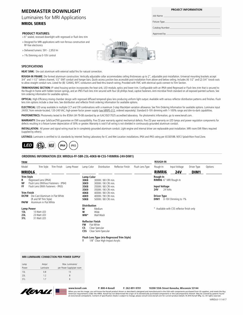
Approved byPRODUCT FEATURES: » 6" sealed, recessed downlight with regressed or flush lens trim
» Designed for MRI applications with non-ferrous construction and RF-free electronics
» Delivered lumens: 591 - 2,953 lm
» 1% Dimming via 0-10V control
Luminaires for MRI Applications
LED IP64 IP65
MRI LUMINAIRE CONNECTION PER POWER SUPPLY Lamp Amps/ Max. Luminaires/
Power Luminaire per Power Supply/per room
13L 0.8 13
23L 1.2 8
31L 1.7 6
Rough-In
TRIM ROUGH-IN
Trim Finish Driver TypeLamp Color Reflector FinishTrim StyleModel Input VoltageLamp Power OptionsDistribution Flush Lens Type
RIMRI6MRIDL6 DIM124V
ORDERING INFORMATION (EX: MRIDL6-FF-5BR-23L-40K8-W-CSS-T-RIMRI6-24V-DIM1)
MRIDL6-111417

When you see this image, you will know the Kenall product shown or described is designed and manufactured in the USA with components purchased from US suppliers, and meets the Buy American requirements under the ARRA. Kenall has not determined the origin of its domestically purchased components or the subcomponents thereof. May be covered by patents found at www.kenall.com/patents. Content of speci�cation sheets is subject to change; please consult www.kenall.com for current product details. © 2016 Kenall Mfg. Co. All rights reserved.
www.kenall.com P: 800-4-Kenall F: 262-891-9701 10200 55th Street Kenosha, Wisconsin 53144
For additional photometry, go to www.kenall.com
MRIDL SERIES
MEDMASTER DOWNLIGHTLuminaires for MRI Applications
OpticLamp Power
Initial Delivered Lumens, By Lamp ColorEfficacy (lm/W)
Input Power
(W)
Estd. L70 LED Life
(hrs)DistributionReflector
Finish30K8 30K9 35K8 35K9 40K8 40K9 50K8
M
CS
13L 956 799 956 809 994 809 1,016 50 - 63 16 75,000
23L 1,777 1,486 1,777 1,504 1,848 1,504 1,888 55 - 70 27 80,000
31L 2,527 2,113 2,527 2,139 2,628 2,139 2,685 57 - 73 37 65,000
CSS
13L 897 750 897 760 933 760 954 47 - 60 16 75,000
23L 1,668 1,395 1,668 1,412 1,735 1,412 1,772 52 - 66 27 80,000
31L 2,372 1,984 2,372 2,008 2,467 2,008 2,521 54 - 68 37 65,000
FW
13L 1,036 866 1,036 876 1,077 876 1,100 54 - 69 16 75,000
23L 1,925 1,610 1,925 1,629 2,002 1,629 2,045 60 - 76 27 80,000
31L 2,738 2,289 2,738 2,317 2,847 2,317 2,909 62 - 79 37 65,000
W
CS
13L 1,051 879 1,051 890 1,093 890 1,117 55 - 70 16 75,000
23L 1,954 1,634 1,954 1,654 2,032 1,654 2,076 61 - 77 27 80,000
31L 2,779 2,324 2,779 2,352 2,890 2,352 2,953 63 - 80 37 65,000
CSS
13L 925 773 925 783 962 783 983 48 - 61 16 75,000
23L 1,719 1,438 1,719 1,455 1,788 1,455 1,827 53 - 68 27 80,000
31L 2,445 2,045 2,445 2,069 2,543 2,069 2,598 55 - 70 37 65,000
FW
13L 1,003 839 1,003 849 1,043 849 1,066 52 - 67 16 75,000
23L 1,864 1,559 1,864 1,578 1,939 1,578 1,981 58 - 73 27 80,000
31L 2,652 2,217 2,652 2,244 2,758 2,244 2,818 60 - 76 37 65,000
WW CSS
13L 783 655 783 663 815 663 832 41 - 52 16 75,000
23L 1,456 1,217 1,456 1,232 1,514 1,232 1,547 45 - 57 27 80,000
31L 2,071 803 2,071 1,752 2,153 1,752 2,200 22 - 59 37 65,000
PERFORMANCE - REGRESSED LENS
Subject to change without notice. Visit www.kenall.com for ies files and additional information.
MRIDL6-111417
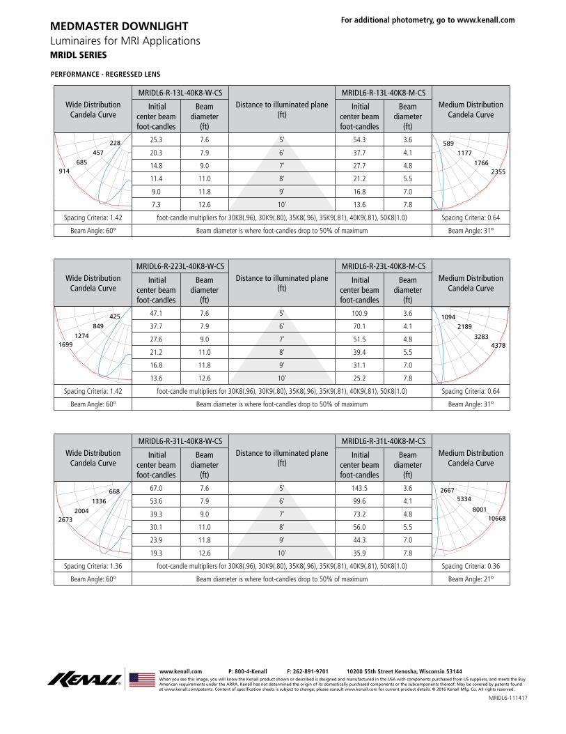
Wide DistributionCandela Curve
MRIDL6-R-13L-40K8-W-CSDistance to illuminated plane
(ft)
MRIDL6-R-13L-40K8-M-CSMedium Distribution
Candela Curve Initial
center beam foot-candles
Beam diameter
(ft)
Initial center beam foot-candles
Beam diameter
(ft)
914685
457
228 25.3 7.6 5' 54.3 3.6
23551766
1177589
20.3 7.9 6' 37.7 4.1
14.8 9.0 7' 27.7 4.8
11.4 11.0 8' 21.2 5.5
9.0 11.8 9' 16.8 7.0
7.3 12.6 10' 13.6 7.8
Spacing Criteria: 1.42 foot-candle multipliers for 30K8(.96), 30K9(.80), 35K8(.96), 35K9(.81), 40K9(.81), 50K8(1.0) Spacing Criteria: 0.64
Beam Angle: 60o Beam diameter is where foot-candles drop to 50% of maximum Beam Angle: 31o
Wide DistributionCandela Curve
MRIDL6-R-31L-40K8-W-CSDistance to illuminated plane
(ft)
MRIDL6-R-31L-40K8-M-CSMedium Distribution
Candela Curve Initial
center beam foot-candles
Beam diameter
(ft)
Initial center beam foot-candles
Beam diameter
(ft)
26732004
1336
668 67.0 7.6 5' 143.5 3.6
106688001
53342667
53.6 7.9 6' 99.6 4.1
39.3 9.0 7' 73.2 4.8
30.1 11.0 8' 56.0 5.5
23.9 11.8 9' 44.3 7.0
19.3 12.6 10' 35.9 7.8
Spacing Criteria: 1.36 foot-candle multipliers for 30K8(.96), 30K9(.80), 35K8(.96), 35K9(.81), 40K9(.81), 50K8(1.0) Spacing Criteria: 0.36
Beam Angle: 60o Beam diameter is where foot-candles drop to 50% of maximum Beam Angle: 21o
Wide DistributionCandela Curve
MRIDL6-R-223L-40K8-W-CSDistance to illuminated plane
(ft)
MRIDL6-R-23L-40K8-M-CSMedium Distribution
Candela Curve Initial
center beam foot-candles
Beam diameter
(ft)
Initial center beam foot-candles
Beam diameter
(ft)
16991274
849
425 47.1 7.6 5' 100.9 3.6
43783283
21891094
37.7 7.9 6' 70.1 4.1
27.6 9.0 7' 51.5 4.8
21.2 11.0 8' 39.4 5.5
16.8 11.8 9' 31.1 7.0
13.6 12.6 10' 25.2 7.8
Spacing Criteria: 1.42 foot-candle multipliers for 30K8(.96), 30K9(.80), 35K8(.96), 35K9(.81), 40K9(.81), 50K8(1.0) Spacing Criteria: 0.64
Beam Angle: 60o Beam diameter is where foot-candles drop to 50% of maximum Beam Angle: 31o
When you see this image, you will know the Kenall product shown or described is designed and manufactured in the USA with components purchased from US suppliers, and meets the Buy American requirements under the ARRA. Kenall has not determined the origin of its domestically purchased components or the subcomponents thereof. May be covered by patents found at www.kenall.com/patents. Content of speci�cation sheets is subject to change; please consult www.kenall.com for current product details. © 2016 Kenall Mfg. Co. All rights reserved.
www.kenall.com P: 800-4-Kenall F: 262-891-9701 10200 55th Street Kenosha, Wisconsin 53144
For additional photometry, go to www.kenall.com
MRIDL SERIES
MEDMASTER DOWNLIGHTLuminaires for MRI Applications
PERFORMANCE - REGRESSED LENS
MRIDL6-111417

When you see this image, you will know the Kenall product shown or described is designed and manufactured in the USA with components purchased from US suppliers, and meets the Buy American requirements under the ARRA. Kenall has not determined the origin of its domestically purchased components or the subcomponents thereof. May be covered by patents found at www.kenall.com/patents. Content of speci�cation sheets is subject to change; please consult www.kenall.com for current product details. © 2016 Kenall Mfg. Co. All rights reserved.
www.kenall.com P: 800-4-Kenall F: 262-891-9701 10200 55th Street Kenosha, Wisconsin 53144
For additional photometry, go to www.kenall.com
MRIDL SERIES
MEDMASTER DOWNLIGHTLuminaires for MRI Applications
OpticLamp Power
Initial Delivered Lumens, By Lamp ColorEfficacy (lm/W)
Input Power
(W)
Estd. L70 LED Life
(hrs)DistributionReflector
Finish30K8 30K9 35K8 35K9 40K8 40K9 50K8
M
CS
13L 862 721 862 730 897 730 916 45 - 57 16 75,000
23L 1,603 1,340 1,603 1,356 1,667 1,356 1,703 50 - 63 27 80,000
31L 2,280 1,906 2,280 1,929 2,371 1,929 2,422 52 - 65 37 65,000
CSS
13L 810 677 810 685 842 685 860 42 - 54 16 75,000
23L 1,505 1,258 1,505 1,273 1,565 1,273 1,599 47 - 59 27 80,000
31L 2,140 1,789 2,140 1,811 2,225 1,811 2,274 48 - 61 37 65,000
FW
13L 934 781 934 791 972 791 993 49 - 62 16 75,000
23L 1,736 1,452 1,736 1,469 1,806 1,469 1,845 54 - 68 27 80,000
31L 2,470 2,065 2,470 2,090 2,568 2,090 2,624 56 - 71 37 65,000
W
CS
13L 948 793 948 802 986 802 1,007 50 - 63 16 75,000
23L 1,762 1,474 1,762 1,491 1,833 1,491 1,873 55 - 69 27 80,000
31L 2,507 2,096 2,507 2,121 2,607 2,121 2,663 57 - 72 37 65,000
CSS
13L 834 698 834 706 868 706 887 44 - 55 16 75,000
23L 1,551 1,297 1,551 1,312 1,613 1,312 1,648 48 - 61 27 80,000
31L 2,206 1,844 2,206 1,867 2,294 1,867 2,343 50 - 63 37 65,000
FW
13L 905 757 905 766 941 766 961 47 - 60 16 75,000
23L 1,682 1,406 1,682 1,423 1,749 1,423 1,787 52 - 66 27 80,000
31L 2,392 2,000 2,392 2,024 2,488 2,024 2,541 54 - 69 37 65,000
WW CSS
13L 707 591 707 598 735 598 751 37 - 47 16 75,000
23L 1,313 1,098 1,313 1,111 1,366 1,111 1,395 41 - 52 27 80,000
31L 1,868 725 1,868 1,581 1,942 1,581 1,984 20 - 54 37 65,000
PERFORMANCE - FLUSH LENS
Subject to change without notice. Visit www.kenall.com for ies files and additional information.
MRIDL6-111417
When you see this image, you will know the Kenall product shown or described is designed and manufactured in the USA with components purchased from US suppliers, and meets the Buy American requirements under the ARRA. Kenall has not determined the origin of its domestically purchased components or the subcomponents thereof. May be covered by patents found at www.kenall.com/patents. Content of speci�cation sheets is subject to change; please consult www.kenall.com for current product details. © 2016 Kenall Mfg. Co. All rights reserved.
www.kenall.com P: 800-4-Kenall F: 262-891-9701 10200 55th Street Kenosha, Wisconsin 53144
For additional photometry, go to www.kenall.com
MRIDL SERIES
MEDMASTER DOWNLIGHTLuminaires for MRI Applications
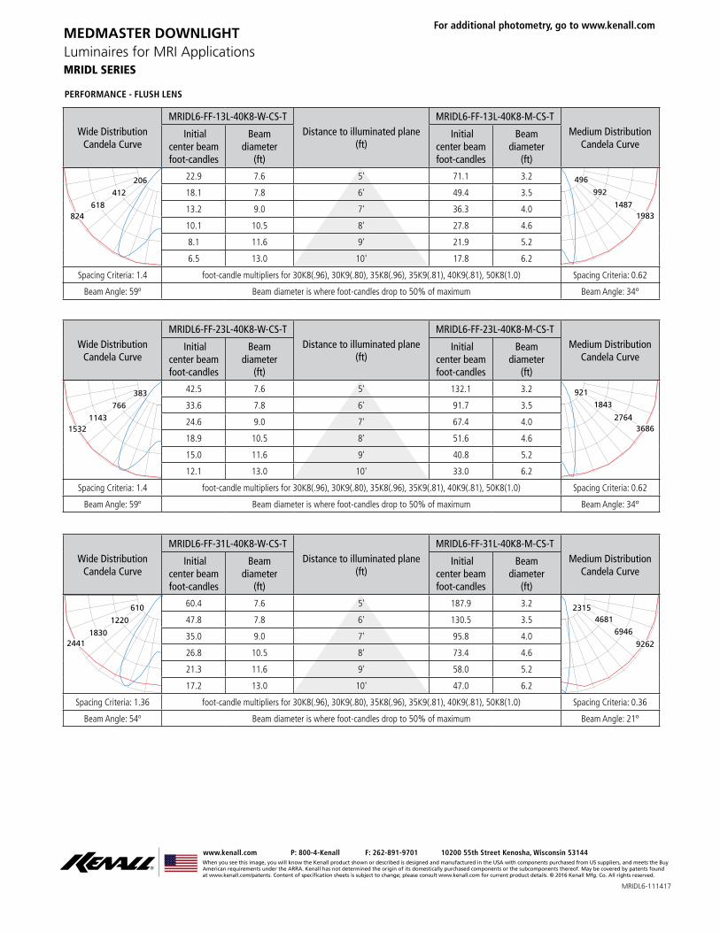
PERFORMANCE - FLUSH LENS
Wide DistributionCandela Curve
MRIDL6-FF-13L-40K8-W-CS-TDistance to illuminated plane
(ft)
MRIDL6-FF-13L-40K8-M-CS-TMedium Distribution
Candela Curve Initial
center beam foot-candles
Beam diameter
(ft)
Initial center beam foot-candles
Beam diameter
(ft)
824618
412
206 22.9 7.6 5' 71.1 3.2
19831487
992
496
18.1 7.8 6' 49.4 3.5
13.2 9.0 7' 36.3 4.0
10.1 10.5 8' 27.8 4.6
8.1 11.6 9' 21.9 5.2
6.5 13.0 10' 17.8 6.2
Spacing Criteria: 1.4 foot-candle multipliers for 30K8(.96), 30K9(.80), 35K8(.96), 35K9(.81), 40K9(.81), 50K8(1.0) Spacing Criteria: 0.62
Beam Angle: 59o Beam diameter is where foot-candles drop to 50% of maximum Beam Angle: 34o
Wide DistributionCandela Curve
MRIDL6-FF-23L-40K8-W-CS-TDistance to illuminated plane
(ft)
MRIDL6-FF-23L-40K8-M-CS-TMedium Distribution
Candela Curve Initial
center beam foot-candles
Beam diameter
(ft)
Initial center beam foot-candles
Beam diameter
(ft)
15321143
766
383 42.5 7.6 5' 132.1 3.2
36862764
1843
921
33.6 7.8 6' 91.7 3.5
24.6 9.0 7' 67.4 4.0
18.9 10.5 8' 51.6 4.6
15.0 11.6 9' 40.8 5.2
12.1 13.0 10' 33.0 6.2
Spacing Criteria: 1.4 foot-candle multipliers for 30K8(.96), 30K9(.80), 35K8(.96), 35K9(.81), 40K9(.81), 50K8(1.0) Spacing Criteria: 0.62
Beam Angle: 59o Beam diameter is where foot-candles drop to 50% of maximum Beam Angle: 34o
Wide DistributionCandela Curve
MRIDL6-FF-31L-40K8-W-CS-TDistance to illuminated plane
(ft)
MRIDL6-FF-31L-40K8-M-CS-TMedium Distribution
Candela Curve Initial
center beam foot-candles
Beam diameter
(ft)
Initial center beam foot-candles
Beam diameter
(ft)
24411830
1220
610 60.4 7.6 5' 187.9 3.2 23154681
9262
694647.8 7.8 6' 130.5 3.5
35.0 9.0 7' 95.8 4.0
26.8 10.5 8' 73.4 4.6
21.3 11.6 9' 58.0 5.2
17.2 13.0 10' 47.0 6.2
Spacing Criteria: 1.36 foot-candle multipliers for 30K8(.96), 30K9(.80), 35K8(.96), 35K9(.81), 40K9(.81), 50K8(1.0) Spacing Criteria: 0.36
Beam Angle: 54o Beam diameter is where foot-candles drop to 50% of maximum Beam Angle: 21o
MRIDL6-111417
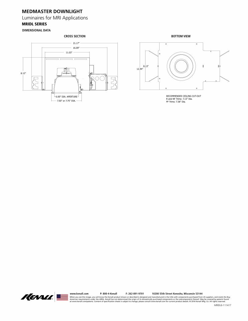
DIMENSIONAL DATA
When you see this image, you will know the Kenall product shown or described is designed and manufactured in the USA with components purchased from US suppliers, and meets the Buy American requirements under the ARRA. Kenall has not determined the origin of its domestically purchased components or the subcomponents thereof. May be covered by patents found at www.kenall.com/patents. Content of speci�cation sheets is subject to change; please consult www.kenall.com for current product details. © 2016 Kenall Mfg. Co. All rights reserved.
www.kenall.com P: 800-4-Kenall F: 262-891-9701 10200 55th Street Kenosha, Wisconsin 53144
MRIDL6-111417
MRIDL SERIES
MEDMASTER DOWNLIGHTLuminaires for MRI Applications
CROSS SECTION BOTTOM VIEW
21.17"
8.12"
16.09"
11.03"
7.50" or 7.75" DIA. 6.00" DIA. APERTURE
12.44" 8.13"
RECOMMENDED CEILING CUT-OUTR and NF Trims: 7.13" Dia.FF Trims: 7.38" Dia.
When you see this image, you will know the Kenall product shown or described is designed and manufactured in the USA with components purchased from US suppliers, and meets the Buy American requirements under the ARRA. Kenall has not determined the origin of its domestically purchased components or the subcomponents thereof. May be covered by patents found at www.kenall.com/patents. Content of speci�cation sheets is subject to change; please consult www.kenall.com for current product details. © 2015 Kenall Mfg. Co. All rights reserved.
www.kenall.com P: 800-4-Kenall F: 262-891-9701 10200 55th Street Kenosha, Wisconsin 53144
1INSTALLATION INSTRUCTIONS
MRIDOWNLIGHT_F-6401_072417
MRI DOWNLIGHTS
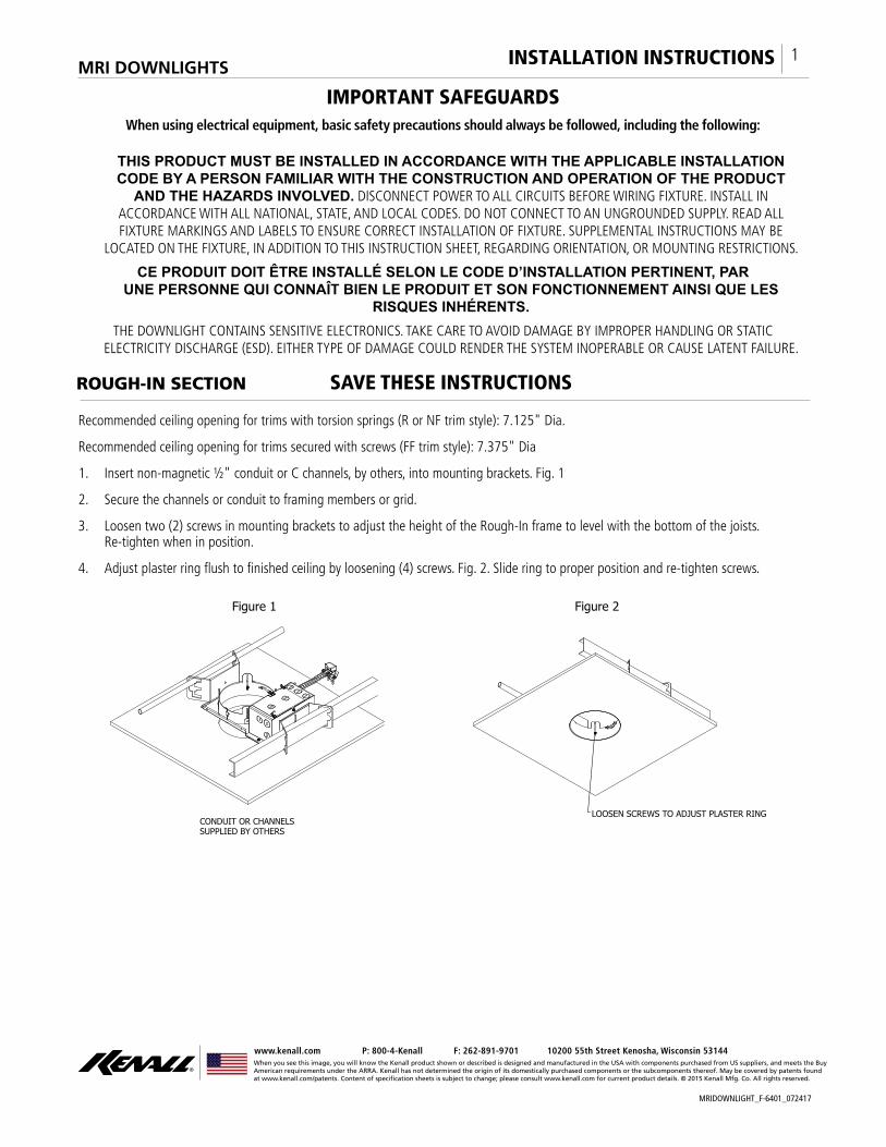
Recommended ceiling opening for trims with torsion springs (R or NF trim style): 7.125" Dia.
Recommended ceiling opening for trims secured with screws (FF trim style): 7.375" Dia
1. Insert non-magnetic ½" conduit or C channels, by others, into mounting brackets. Fig. 1
2. Secure the channels or conduit to framing members or grid.
3. Loosen two (2) screws in mounting brackets to adjust the height of the Rough-In frame to level with the bottom of the joists. Re-tighten when in position.
4. Adjust plaster ring fl ush to fi nished ceiling by loosening (4) screws. Fig. 2. Slide ring to proper position and re-tighten screws.
IMPORTANT SAFEGUARDSWhen using electrical equipment, basic safety precautions should always be followed, including the following:
THIS PRODUCT MUST BE INSTALLED IN ACCORDANCE WITH THE APPLICABLE INSTALLATION CODE BY A PERSON FAMILIAR WITH THE CONSTRUCTION AND OPERATION OF THE PRODUCT
AND THE HAZARDS INVOLVED. DISCONNECT POWER TO ALL CIRCUITS BEFORE WIRING FIXTURE. INSTALL IN ACCORDANCE WITH ALL NATIONAL, STATE, AND LOCAL CODES. DO NOT CONNECT TO AN UNGROUNDED SUPPLY. READ ALL FIXTURE MARKINGS AND LABELS TO ENSURE CORRECT INSTALLATION OF FIXTURE. SUPPLEMENTAL INSTRUCTIONS MAY BE
LOCATED ON THE FIXTURE, IN ADDITION TO THIS INSTRUCTION SHEET, REGARDING ORIENTATION, OR MOUNTING RESTRICTIONS.
CE PRODUIT DOIT ÊTRE INSTALLÉ SELON LE CODE D’INSTALLATION PERTINENT, PAR UNE PERSONNE QUI CONNAÎT BIEN LE PRODUIT ET SON FONCTIONNEMENT AINSI QUE LES
RISQUES INHÉRENTS.THE DOWNLIGHT CONTAINS SENSITIVE ELECTRONICS. TAKE CARE TO AVOID DAMAGE BY IMPROPER HANDLING OR STATIC
ELECTRICITY DISCHARGE (ESD). EITHER TYPE OF DAMAGE COULD RENDER THE SYSTEM INOPERABLE OR CAUSE LATENT FAILURE.
SAVE THESE INSTRUCTIONS
LOOSEN SCREWS TO ADJUST PLASTER RING
Figure 2
CONDUIT OR CHANNELS SUPPLIED BY OTHERS
Figure 1
ROUGH-IN SECTION
When you see this image, you will know the Kenall product shown or described is designed and manufactured in the USA with components purchased from US suppliers, and meets the Buy American requirements under the ARRA. Kenall has not determined the origin of its domestically purchased components or the subcomponents thereof. May be covered by patents found at www.kenall.com/patents. Content of speci�cation sheets is subject to change; please consult www.kenall.com for current product details. © 2015 Kenall Mfg. Co. All rights reserved.
www.kenall.com P: 800-4-Kenall F: 262-891-9701 10200 55th Street Kenosha, Wisconsin 53144
2INSTALLATION INSTRUCTIONS
MRIDOWNLIGHT_F-6401_072417
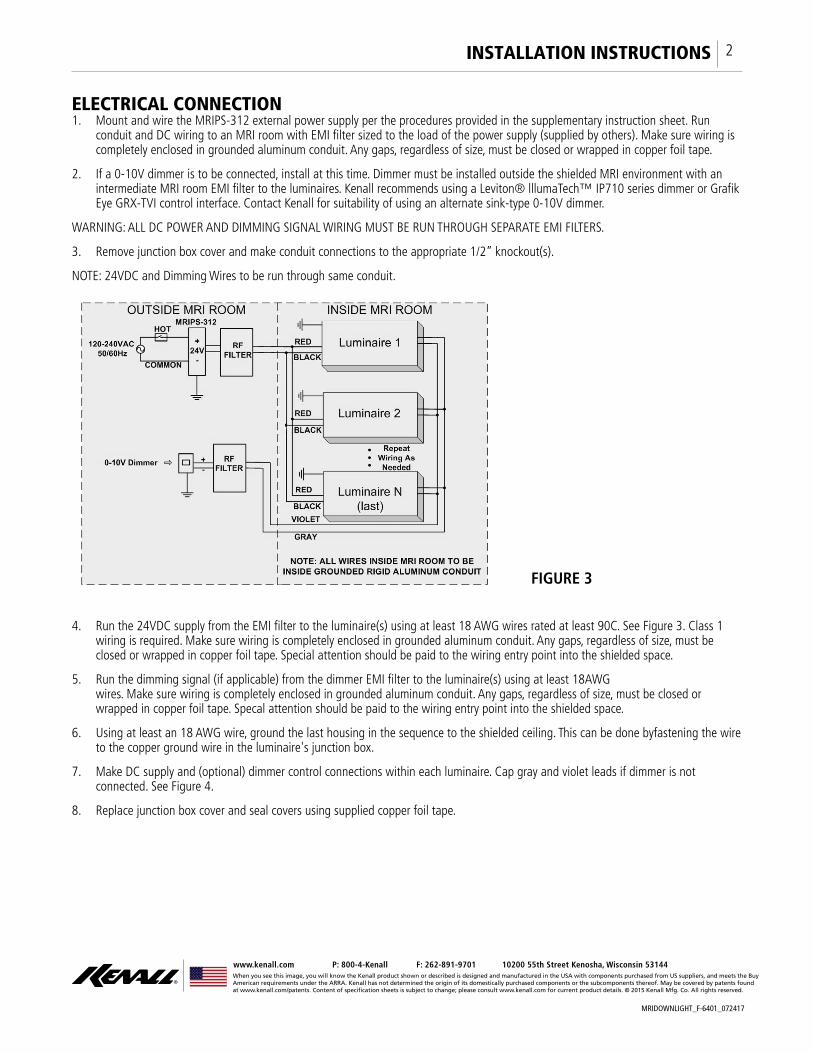
FIGURE 3
ELECTRICAL CONNECTION 1. Mount and wire the MRIPS-312 external power supply per the procedures provided in the supplementary instruction sheet. Run
conduit and DC wiring to an MRI room with EMI fi lter sized to the load of the power supply (supplied by others). Make sure wiring is completely enclosed in grounded aluminum conduit. Any gaps, regardless of size, must be closed or wrapped in copper foil tape.
2. If a 0-10V dimmer is to be connected, install at this time. Dimmer must be installed outside the shielded MRI environment with an intermediate MRI room EMI fi lter to the luminaires. Kenall recommends using a Leviton® lllumaTech™ IP710 series dimmer or Grafi k Eye GRX-TVI control interface. Contact Kenall for suitability of using an alternate sink-type 0-10V dimmer.
WARNING: ALL DC POWER AND DIMMING SIGNAL WIRING MUST BE RUN THROUGH SEPARATE EMI FILTERS.
3. Remove junction box cover and make conduit connections to the appropriate 1/2” knockout(s).
NOTE: 24VDC and Dimming Wires to be run through same conduit.
4. Run the 24VDC supply from the EMI fi lter to the luminaire(s) using at least 18 AWG wires rated at least 90C. See Figure 3. Class 1 wiring is required. Make sure wiring is completely enclosed in grounded aluminum conduit. Any gaps, regardless of size, must be closed or wrapped in copper foil tape. Special attention should be paid to the wiring entry point into the shielded space.
5. Run the dimming signal (if applicable) from the dimmer EMI fi lter to the luminaire(s) using at least 18AWG wires. Make sure wiring is completely enclosed in grounded aluminum conduit. Any gaps, regardless of size, must be closed or wrapped in copper foil tape. Specal attention should be paid to the wiring entry point into the shielded space.
6. Using at least an 18 AWG wire, ground the last housing in the sequence to the shielded ceiling. This can be done byfastening the wire to the copper ground wire in the luminaire's junction box.
7. Make DC supply and (optional) dimmer control connections within each luminaire. Cap gray and violet leads if dimmer is not connected. See Figure 4.
8. Replace junction box cover and seal covers using supplied copper foil tape.
When you see this image, you will know the Kenall product shown or described is designed and manufactured in the USA with components purchased from US suppliers, and meets the Buy American requirements under the ARRA. Kenall has not determined the origin of its domestically purchased components or the subcomponents thereof. May be covered by patents found at www.kenall.com/patents. Content of speci�cation sheets is subject to change; please consult www.kenall.com for current product details. © 2015 Kenall Mfg. Co. All rights reserved.
www.kenall.com P: 800-4-Kenall F: 262-891-9701 10200 55th Street Kenosha, Wisconsin 53144
3INSTALLATION INSTRUCTIONS
MRIDOWNLIGHT_F-6401_072417
This product is warranted by Kenall to be free of defects in workmanship and materials for a period of one year from the date of the invoice. The external DC power supply carries a three year warranty from the date of the invoice.
Kenall reserves the right to issue credit, repair, or replace the defective merchandise, at its discretion, upon notifi cation and confi rmation by its local representative of the defect. Kenall also reserves the right to test and examine the defective product if the defect is questionable and to deny the warranty herein for any product altered, improperly installed, or installed in applications for which it is not intended. This includes operation in ambient temperatures above stated limits for any length of time. Failure by electrical surge shall not be covered under warranty.
Kenall assumes no responsibility for labor or freight costs incurred in connection with the installation, removal, or replacement of products determined to be defective or any other consequential or incidental damages arising from the use of the product. Kenall’s entire liability on any claim of loss or damage resulting from a defective product is limited to the replacement price of the product.
The foregoing warranty is exclusive of all other warranties and no other warranties of any kind are expressed or implied.
WARRANTY
CUSTOMER SERVICE
For technical assistance, call 1-800-4KENALL (1-800-453-6255). For additional instructions, go to www.kenall.com/Installs
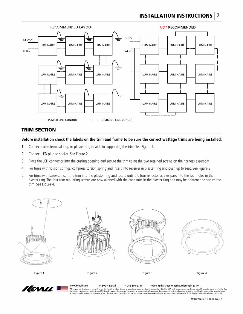
LUMINAIRE LUMINAIRE LUMINAIRE
LUMINAIRE LUMINAIRE LUMINAIRE
LUMINAIRE LUMINAIRE LUMINAIRE
LUMINAIRE LUMINAIRE LUMINAIRE
LUMINAIRE LUMINAIRE LUMINAIRE
LUMINAIRE LUMINAIRE LUMINAIRE
0-10V
24 VDC0-10V
24 VDC
DIMMING LINE CONDUITPOWER LINE CONDUIT
RECOMMENDED LAYOUT NOT RECOMMENDED
Wiring from fi xture to fi xture and grounding the fi nal fi xture is recommended.
When you see this image, you will know the Kenall product shown or described is designed and manufactured in the USA with components purchased from US suppliers, and meets the Buy American requirements under the ARRA. Kenall has not determined the origin of its domestically purchased components or the subcomponents thereof. May be covered by patents found at www.kenall.com/patents. Content of speci�cation sheets is subject to change; please consult www.kenall.com for current product details. © 2015 Kenall Mfg. Co. All rights reserved.
www.kenall.com P: 800-4-Kenall F: 262-891-9701 10200 55th Street Kenosha, Wisconsin 53144
1INSTALLATION INSTRUCTIONS
MRIDOWNLIGHT_F-6633_072417
MRI DOWNLIGHTS
Before installation check the labels on the trim and frame to be sure the correct wattage trims are being installed.
1. Connect cable terminal loop to plaster ring to aide in supporting the trim. See Figure 1.
2. Connect LED plug to socket. See Figure 2.
3. Place the LED connector into the casting opening and secure the trim using the two retained screws on the harness assembly.
4. For trims with torsion springs, compress torsion spring and insert into receiver in plaster ring and push up to seat. See Figure 3.
5. For trims with screws, insert the trim into the plaster ring and rotate until the four refl ector screws pass into the four holes in the plaster ring. The four trim mounting screws are now aligned with the cage nuts in the plaster ring and may be tightened to secure the trim. See Figure 4.
IMPORTANT SAFEGUARDSWhen using electrical equipment, basic safety precautions should always be followed, including the following:
THIS PRODUCT MUST BE INSTALLED IN ACCORDANCE WITH THE APPLICABLE INSTALLATION CODE BY A PERSON FAMILIAR WITH THE CONSTRUCTION AND OPERATION OF THE PRODUCT
AND THE HAZARDS INVOLVED. DISCONNECT POWER TO ALL CIRCUITS BEFORE WIRING FIXTURE. INSTALL IN ACCORDANCE WITH ALL NATIONAL, STATE, AND LOCAL CODES. DO NOT CONNECT TO AN UNGROUNDED SUPPLY. READ ALL FIXTURE MARKINGS AND LABELS TO ENSURE CORRECT INSTALLATION OF FIXTURE. SUPPLEMENTAL INSTRUCTIONS MAY BE
LOCATED ON THE FIXTURE, IN ADDITION TO THIS INSTRUCTION SHEET, REGARDING ORIENTATION, OR MOUNTING RESTRICTIONS.
CE PRODUIT DOIT ÊTRE INSTALLÉ SELON LE CODE D’INSTALLATION PERTINENT, PAR UNE PERSONNE QUI CONNAÎT BIEN LE PRODUIT ET SON FONCTIONNEMENT AINSI QUE LES
RISQUES INHÉRENTS.THE DOWNLIGHT CONTAINS SENSITIVE ELECTRONICS. TAKE CARE TO AVOID DAMAGE BY IMPROPER HANDLING OR STATIC
ELECTRICITY DISCHARGE (ESD). EITHER TYPE OF DAMAGE COULD RENDER THE SYSTEM INOPERABLE OR CAUSE LATENT FAILURE.
SAVE THESE INSTRUCTIONS
Figure 1 Figure 2 Figure 3 Figure 4
TRIM SECTION
When you see this image, you will know the Kenall product shown or described is designed and manufactured in the USA with components purchased from US suppliers, and meets the Buy American requirements under the ARRA. Kenall has not determined the origin of its domestically purchased components or the subcomponents thereof. May be covered by patents found at www.kenall.com/patents. Content of speci�cation sheets is subject to change; please consult www.kenall.com for current product details. © 2015 Kenall Mfg. Co. All rights reserved.
www.kenall.com P: 800-4-Kenall F: 262-891-9701 10200 55th Street Kenosha, Wisconsin 53144
2INSTALLATION INSTRUCTIONS
MRIDOWNLIGHT_F-6633_072417
This product is warranted by Kenall to be free of defects in workmanship and materials for a period of one year from the date of the invoice. The external DC power supply carries a three year warranty from the date of the invoice.
Kenall reserves the right to issue credit, repair, or replace the defective merchandise, at its discretion, upon notifi cation and confi rmation by its local representative of the defect. Kenall also reserves the right to test and examine the defective product if the defect is questionable and to deny the warranty herein for any product altered, improperly installed, or installed in applications for which it is not intended. This includes operation in ambient temperatures above stated limits for any length of time. Failure by electrical surge shall not be covered under warranty.
Kenall assumes no responsibility for labor or freight costs incurred in connection with the installation, removal, or replacement of products determined to be defective or any other consequential or incidental damages arising from the use of the product. Kenall’s entire liability on any claim of loss or damage resulting from a defective product is limited to the replacement price of the product.
The foregoing warranty is exclusive of all other warranties and no other warranties of any kind are expressed or implied.
WARRANTY
CUSTOMER SERVICE
For technical assistance, call 1-800-4KENALL (1-800-453-6255). For additional instructions, go to www.kenall.com/Installs
10

When you see this image, you will know the Kenall product shown or described is designed and manufactured in the USA with components purchased from US suppliers, and meets the Buy American requirements under the ARRA. Kenall has not determined the origin of its domestically purchased components or the subcomponents thereof. May be covered by patents found at www.kenall.com/patents. Content of speci�cation sheets is subject to change; please consult www.kenall.com for current product details. © 2015 Kenall Mfg. Co. All rights reserved.
www.kenall.com P: 800-4-Kenall F: 262-891-9701 10200 55th Street Kenosha, Wisconsin 53144
3INSTALLATION INSTRUCTIONS
MRIDOWNLIGHT_F-6633_072417
CUSTOMER ACKNOWLEDGEMENT MRI INSTALLATION REGISTRATION FORM
Customer acknowledges that the attached Installation Registration Form will be provided to the installer to sign and return to Kenall afterinstallation is complete. For warranty purposes, please fill out this form and return to
Kenall by fax at (847) 360-1781.
I certify that the lighting installation for the listed MRI suite location is completed per the provided installation instructions and to the best of my abilities.
Please check off items to denote status:
Installation instruction sheets for MRIPS-312 power supply and individual luminaire(s) read and followed. MRIPS-312 power supply and EMI fi lters are located outside the shielded enclosure. All DC supply wiring is completely enclosed within grounded aluminum conduit. Installation has no ungrounded/unshielded portions of conduit or openings of any size or shape. All dimming signal wiring is completely enclosed within grounded aluminum conduit. Installation has no ungrounded/unshielded portions of conduit or openings of any size or shape. Check here if dimming is not applicable: MRI Room EMI fi lters for the 24VDC supply are of the type intended for MRI suites and are sized to the electrical load. DC supply power and dimming signal are NOT running through the same EMI fi lter. Check here if dimming is not applicable: Lighting system fully tested (including dimming operation, if applicable) while MRI machine is in idle and scan operation mode.
If any of these steps cannot be completed or you need technical assistance, please contact Kenall Technical Support at 1-800-4KENALL (1-800-453-6255).
Electrical Contractor
Name: ___________________________________
City/State: ________________________________
Phone:___________________________________
Installation Date: ___________________________
Installation Site
Name: ___________________________________
City/State: ________________________________
FAX FORM TO (847) 360-1781
(Do not write below line)
Kenall Received By: ___________________________________ Received Date: ________________________________
11