Embed Size (px)
Citation preview
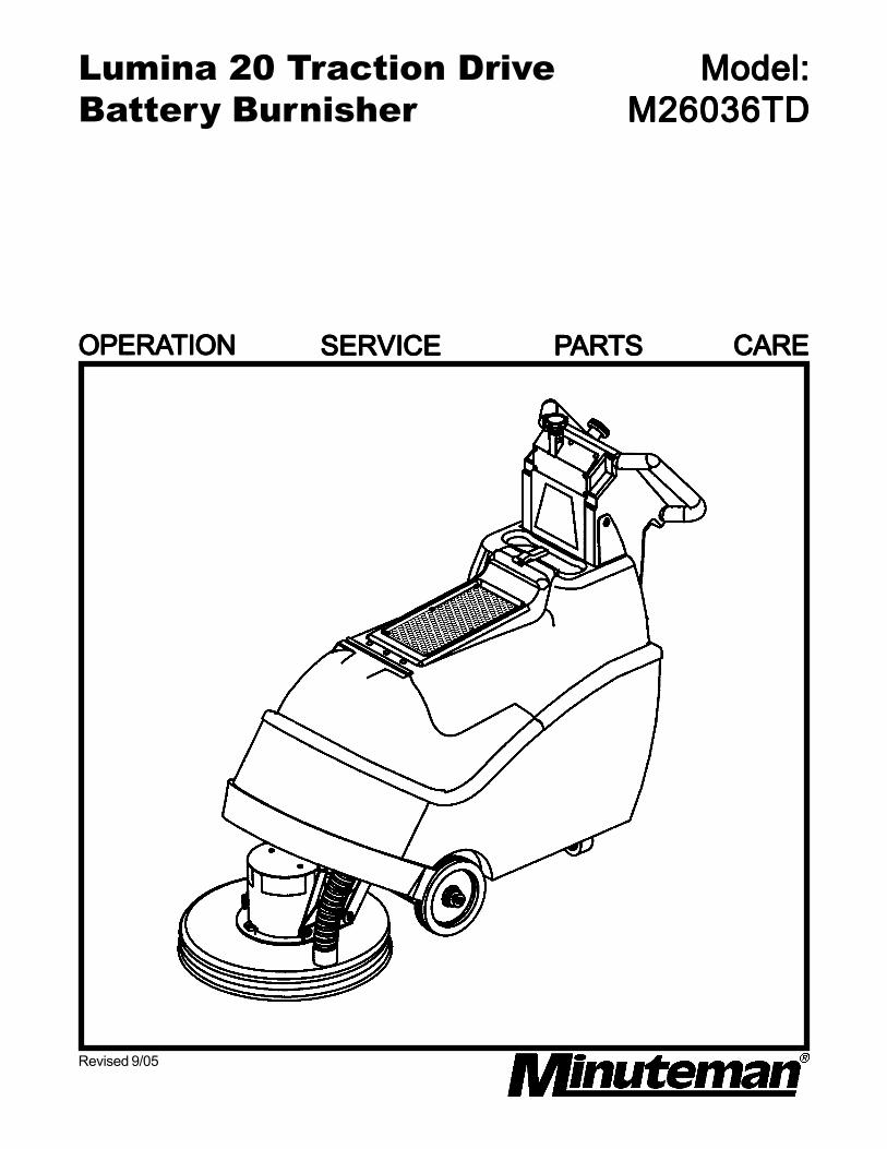
Lumina 20 Traction DriveBattery Burnisher
Model:Model:Model:Model:Model:M26036TDM26036TDM26036TDM26036TDM26036TD
Revised 9/05
OPERAOPERAOPERAOPERAOPERATIONTIONTIONTIONTION SERVICESERVICESERVICESERVICESERVICE PPPPPARARARARARTSTSTSTSTS CARECARECARECARECARE
TTTTTable Of Contentable Of Contentable Of Contentable Of Contentable Of ContentsssssImportant Safety Instructions ...............................................................1Operating Instructions
Inspection ..................................................................................... 2Electrical ...................................................................................... 2Batteries .......................................................................................2Operation ..................................................................................... 2After Use ...................................................................................... 2Maintenance ................................................................................. 2Floor Seal Strip .............................................................................2Battery Service And Installation .....................................................3Charging Of Batteries ................................................................... 3Machine Overview ........................................................................ 3Dashboard Control Panel ............................................................. 3Pad Installation .............................................................................4Pad Pressure Adjustments ............................................................ 4Circuit Breaker Protection............................................................. 4Carbon Brush Replacement .......................................................... 4Carbon Brush Service................................................................... 4
Exploded ViewsBase Assembly & Parts List .......................................................... 5 - 6Mainframe Assembly & Parts List ................................................. 7 - 8Housing Assembly & Parts List .....................................................9Pad Driver Assembly & Parts List ................................................. 10Pressure Control Assembly & Parts List ........................................11Electrical Assembly & Parts List ....................................................12Console Assembly & Parts List .....................................................13 - 14Dashboard Assebly & Parts List ...................................................15
Schematic Diagrams ......................................................................... 16 - 18Limited Warranty ................................................................................Back Cover
1
IMPORIMPORIMPORIMPORIMPORTTTTTANTANTANTANTANT SAFETY SAFETY SAFETY SAFETY SAFETY INSTRUCTIONS INSTRUCTIONS INSTRUCTIONS INSTRUCTIONS INSTRUCTIONS
CAUTION:CAUTION:CAUTION:CAUTION:CAUTION: Operators must read and understand this manual before operating or maintainingthis machine.
Keep hands and feet clear of moving parts while machine is in operation.
Disconnect the power to the machine by pressing the red Emergency Disconnect Button whencharging batteries or during installation or removal of pads.
During operation, loose objects on the floor can become dangerous projectiles if struck by the highspeed pad. Special attention should be paid in removing or avoiding loose floor tile, electricalcables, telephone connection boxes.
Electrical motors and components can cause an explosion when operated near explosive materialsor vapors. Do not operate this machine near flammable materials such as solvents, thinners, fuels,grain dust, etc.
Keep machine moving to reduce the risk of damaging floor finish and floor.
Make sure the red Emergency Disconnect Button is pressed and the battery connector is unpluggedfrom the machine before performing any maintenance procedures.
Store or park this machine on a level surface only.
These machines are designed for level floor operation only. Do not operate on ramps or inclines.
Battery acid can cause burns. When working on or around batteries, wear protective clothing andsafety glasses. Remove metal jewelry. Do not lay tools or metal objects on top of batteries.
Charging batteries generates explosive gases. DO NOT CHARGE BATTERIES WHEN OPENFLAMES OR SPARKS ARE PRESENT. DO NOT SMOKE. Make sure the charger is turned offbefore disconnecting it from the machine. Charge the batteries in a well-ventilated area with thebattery cover removed completely.
Maintenance and repairs must be performed by authorized personnel.
SASASASASAVE VE VE VE VE THESE INSTRUCTIONSTHESE INSTRUCTIONSTHESE INSTRUCTIONSTHESE INSTRUCTIONSTHESE INSTRUCTIONS
2
OPERAOPERAOPERAOPERAOPERATING INSTRUCTIONSTING INSTRUCTIONSTING INSTRUCTIONSTING INSTRUCTIONSTING INSTRUCTIONS
INSPECTIONINSPECTIONINSPECTIONINSPECTIONINSPECTIONCarefully unpack and inspect your burnisher for shipping damage. Each unit is tested and thoroughlyinspected before shipment; any damage is the responsibility of the delivery carrier who should benotified immediately.
ELECTRICALELECTRICALELECTRICALELECTRICALELECTRICALThis machine is battery operated and designed to operate on 36 volts DC (3) 12 volt batteries.
BABABABABATTERIESTTERIESTTERIESTTERIESTTERIESBurnishers are shipped with batteries. (3 required)Part No. 956210 12V 210AH 20 Hr. Rate (Optional)We do not recommend mixing AMP hour capacities. Any alternate battery sets can be used ifthey equal physical size and capacity. See next page for service and installation.
OPERAOPERAOPERAOPERAOPERATIONTIONTIONTIONTIONBefore starting, familiarize yourself with the machine and its controls (see “Machine Overview” and“Control Panel” diagrams). To turn the machine ON, do the following:
1. Make sure 20” high speed pad is used. Make sure the pad is installed on the machine byfollowing instructions under”Pad Installation.”
2. Make sure that no battery charger is plugged into the recharge port.3. Lift the red emergency disconnect button so it is in the up position.4. Lower the pad driver assembly by pushing the pedal slightly outward on the machine (unlock it),
and then release it slowly.5. Turn the power switch to the ON position. The pad driver will then slowly adjust itself to the floor.
Move forward in a straight line, check the reading on the Operating Range Meter and makesure you are in the Green Zone.
6. Place hands on the bails and squeeze the bail levers to start the operation of the machine.Move forward in a straight line, check the reading on the Operating Range Meter and makesure you are in the Green Zone.
7. Adjust the pad pressure as needed by turning the knob accordingly. (See Pad PressureAdjustments.)
8. Adjust speed as needed by turning the speed control knob accordingly.
AFTER USEAFTER USEAFTER USEAFTER USEAFTER USETo raise the pad driver, push down until the pedal arm engages into the pedal catch. Turn machineoff by turning the key switch on the control panel. Machine can be cleaned with a mild detergent anda damp cloth. Batteries should be charged after each use or when the battery condition metershows a low charge. Once the battery charger reads 0 amps, the batteries are recharged. Thisshould take approximately 8 hours if the batteries are completely discharged.
MAINTENANCEMAINTENANCEMAINTENANCEMAINTENANCEMAINTENANCEPeriodically remove batteries from machine. Clean the batteries and battery tray with a solution ofbaking soda and water. Check all battery cables and wiring for signs of damage and wear. Replaceas needed. Grease front wheel and rear caster zerks once a month for best operation.
FLOOR SEAL STRIPFLOOR SEAL STRIPFLOOR SEAL STRIPFLOOR SEAL STRIPFLOOR SEAL STRIPWhen the floor seal strip show signs of excessive wear, seal should be replaced. The strip can beremoves by loosening the screw on the retainer strap until the seal can slide off of the pad shroudhousing. To install new seal, slip the retainer strap over the new seal strip and pad shroud. Make surethe seal is seated equally around the perimeter and the holes on the floor seal are oriented towardsthe back portion of the shroud.
3
BABABABABATTERTTERTTERTTERTTERYYYYY SER SER SER SER SERVICE VICE VICE VICE VICE AND INSTAND INSTAND INSTAND INSTAND INSTALLAALLAALLAALLAALLATIONTIONTIONTIONTIONWWWWWARNING:ARNING:ARNING:ARNING:ARNING: Battery acid can cause burns. When working on or around batteries, wear protectiveclothing and safety glasses. Remove metal jewelry. Do not lay tools or metal objects on top ofbatteries.
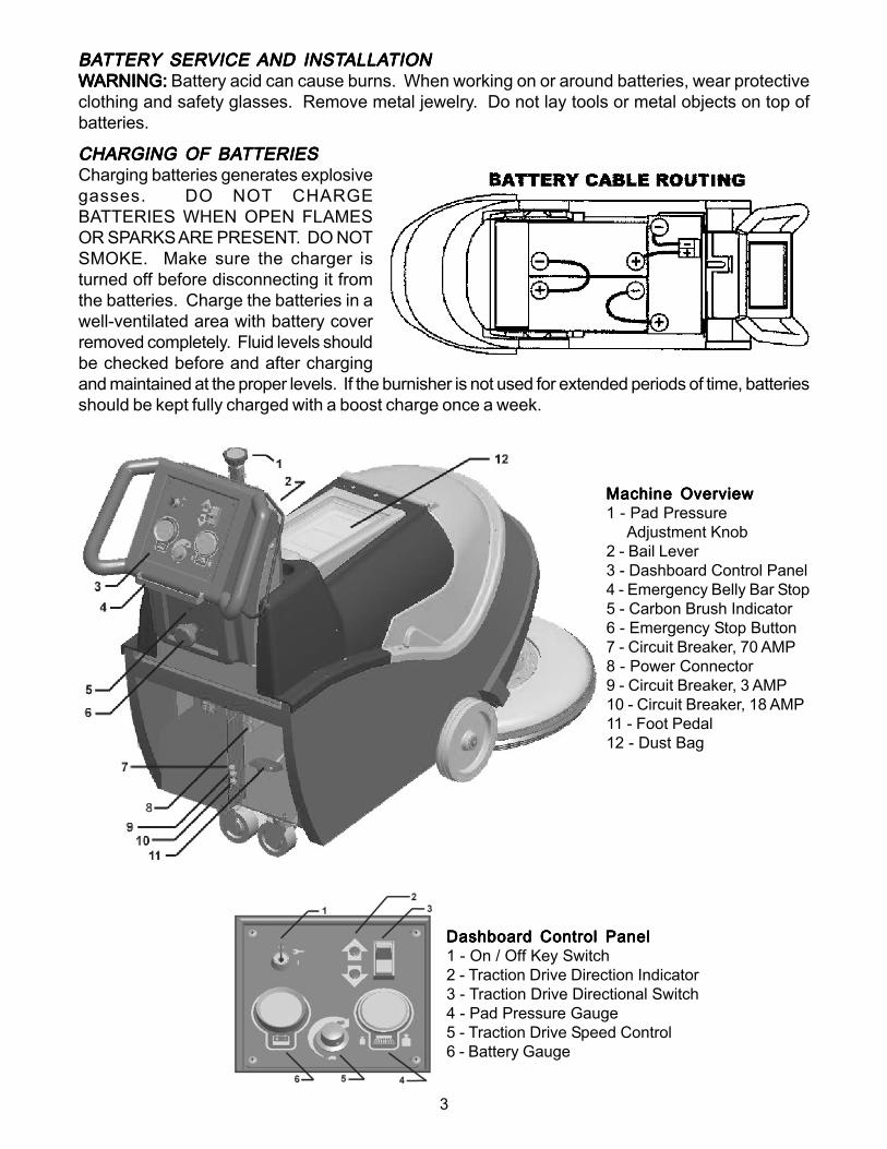
CHARGING OF BACHARGING OF BACHARGING OF BACHARGING OF BACHARGING OF BATTERIESTTERIESTTERIESTTERIESTTERIESCharging batteries generates explosivegasses. DO NOT CHARGEBATTERIES WHEN OPEN FLAMESOR SPARKS ARE PRESENT. DO NOTSMOKE. Make sure the charger isturned off before disconnecting it fromthe batteries. Charge the batteries in awell-ventilated area with battery coverremoved completely. Fluid levels shouldbe checked before and after chargingand maintained at the proper levels. If the burnisher is not used for extended periods of time, batteriesshould be kept fully charged with a boost charge once a week.
Dashboard Control PanelDashboard Control PanelDashboard Control PanelDashboard Control PanelDashboard Control Panel1 - On / Off Key Switch2 - Traction Drive Direction Indicator3 - Traction Drive Directional Switch4 - Pad Pressure Gauge5 - Traction Drive Speed Control6 - Battery Gauge
Machine OverviewMachine OverviewMachine OverviewMachine OverviewMachine Overview1 - Pad Pressure Adjustment Knob2 - Bail Lever3 - Dashboard Control Panel4 - Emergency Belly Bar Stop5 - Carbon Brush Indicator6 - Emergency Stop Button7 - Circuit Breaker, 70 AMP8 - Power Connector9 - Circuit Breaker, 3 AMP10 - Circuit Breaker, 18 AMP11 - Foot Pedal12 - Dust Bag
4
PPPPPAD PRESSURE AD PRESSURE AD PRESSURE AD PRESSURE AD PRESSURE ADJUSTMENTSADJUSTMENTSADJUSTMENTSADJUSTMENTSADJUSTMENTSThe pad pressure adjust knob is located on the top of the control console. Counter-clockwise rotationincreases pad pressure, the opposite rotation decreases. Different floors, conditions, and padsproduce carying pad load conditions. Ideal burnishing conditions are maintained while the operatingrange meter remains in the Green Zone. If the meter reads in the Red Zone decrease the padpressure. When the machine is operated in the Red Zone for a long period of time motor overloadwill occur and the 70-amp circuit breaker for the motor will trip. If the motor circuit trips:
1. Check pad condition.2. Decrease pad pressure.3. Reset circuit breaker.
CIRCUIT BREAKER PROTECTIONCIRCUIT BREAKER PROTECTIONCIRCUIT BREAKER PROTECTIONCIRCUIT BREAKER PROTECTIONCIRCUIT BREAKER PROTECTION70 amp circuit breaker protects pad driver motor form excessive overload conditions.3 amp circuit breaker protects control circuits against possible electrical shorts.If either circuit breaker trips, first determine the cause and correct the condition before resetting thebreakers.
CARBON BRUSH REPLACEMENTCARBON BRUSH REPLACEMENTCARBON BRUSH REPLACEMENTCARBON BRUSH REPLACEMENTCARBON BRUSH REPLACEMENTDesign life of carbon brushes is between 1800-2000 hours. Replace brushes if worn to 3/8" or less,broken, or chipped. All carbon brushes should be replaced when motor is serviced. Four (4) arerequired, P/N 572003. Red indicator on control panel (above Emergency Disconnect Button, belowthe Dashboard) will glow when carbon brush service is required.
CARBON BRUSH SERVICECARBON BRUSH SERVICECARBON BRUSH SERVICECARBON BRUSH SERVICECARBON BRUSH SERVICE1. Disconnect batteries from machine.2. Remove two screws that hold dust control housing and motor cover to motor.3. Blow out top of motor with air line.4. Loosen screw and remove carbon brush lead.5. Slide brush spring off the back of carbon brush and remove brush.6. Reverse order for installation of new carbon brushes.
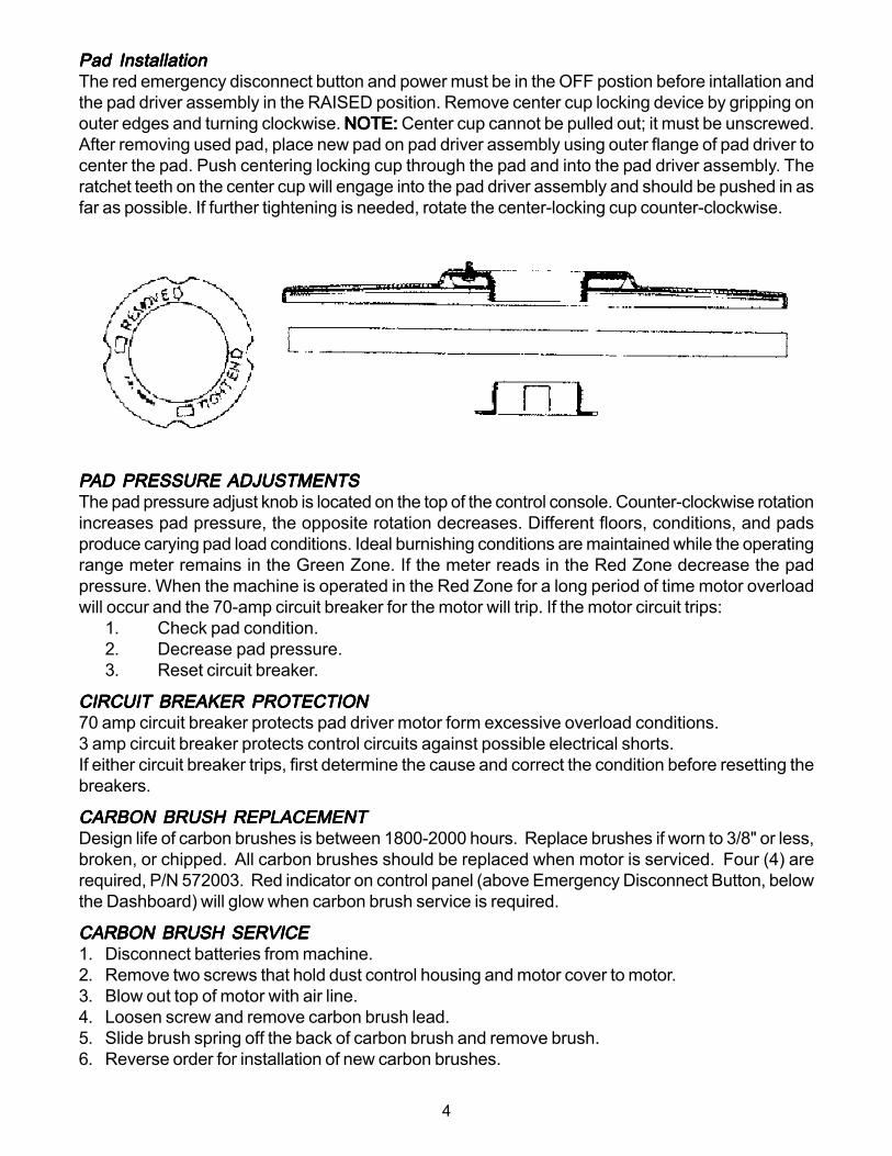
Pad InstallationPad InstallationPad InstallationPad InstallationPad InstallationThe red emergency disconnect button and power must be in the OFF postion before intallation andthe pad driver assembly in the RAISED position. Remove center cup locking device by gripping onouter edges and turning clockwise. NOTE: NOTE: NOTE: NOTE: NOTE: Center cup cannot be pulled out; it must be unscrewed.After removing used pad, place new pad on pad driver assembly using outer flange of pad driver tocenter the pad. Push centering locking cup through the pad and into the pad driver assembly. Theratchet teeth on the center cup will engage into the pad driver assembly and should be pushed in asfar as possible. If further tightening is needed, rotate the center-locking cup counter-clockwise.
5
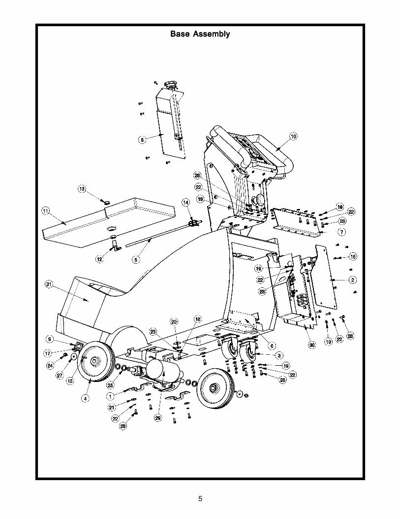
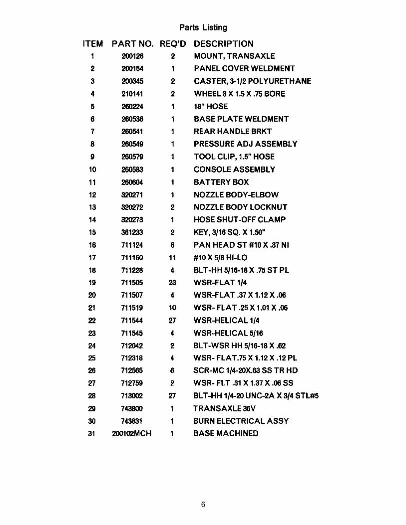
Base Base Base Base Base AssemblyAssemblyAssemblyAssemblyAssembly
6
Parts ListingParts ListingParts ListingParts ListingParts Listing
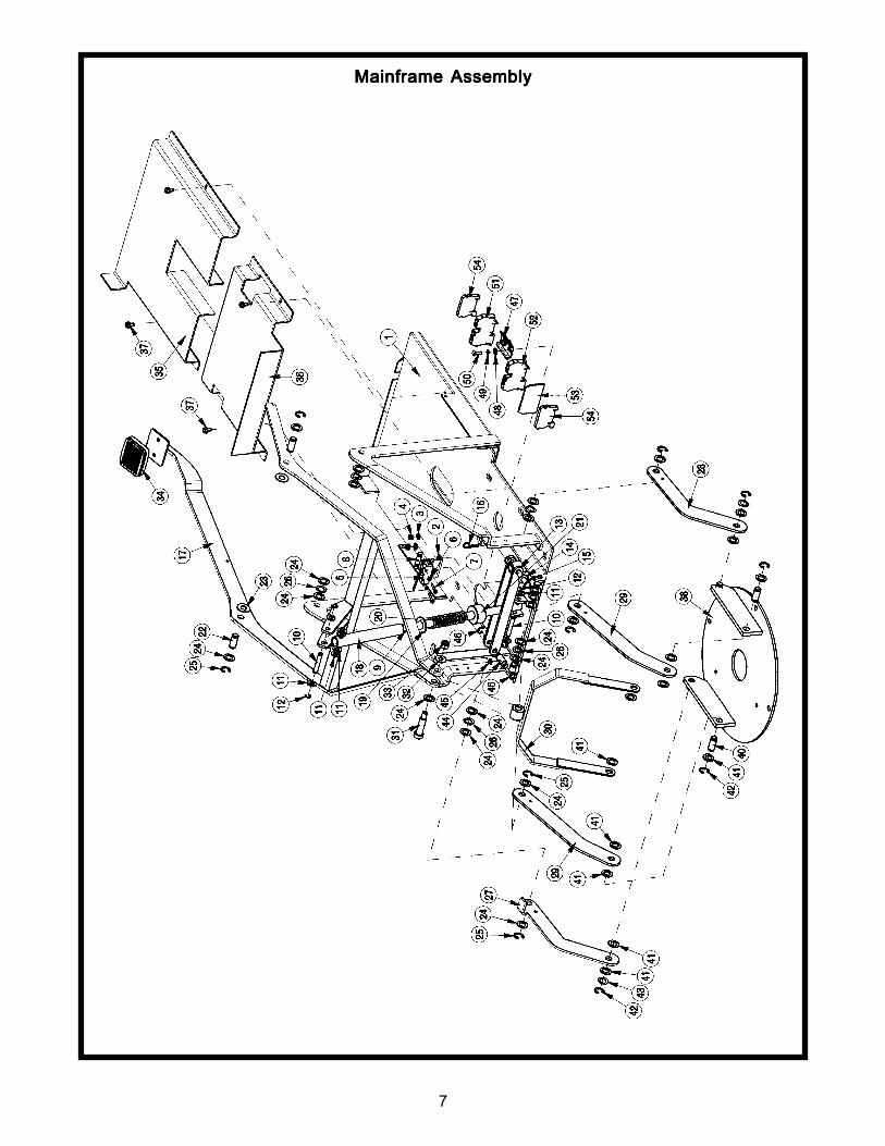
7
Mainframe Mainframe Mainframe Mainframe Mainframe AssemblyAssemblyAssemblyAssemblyAssembly
8
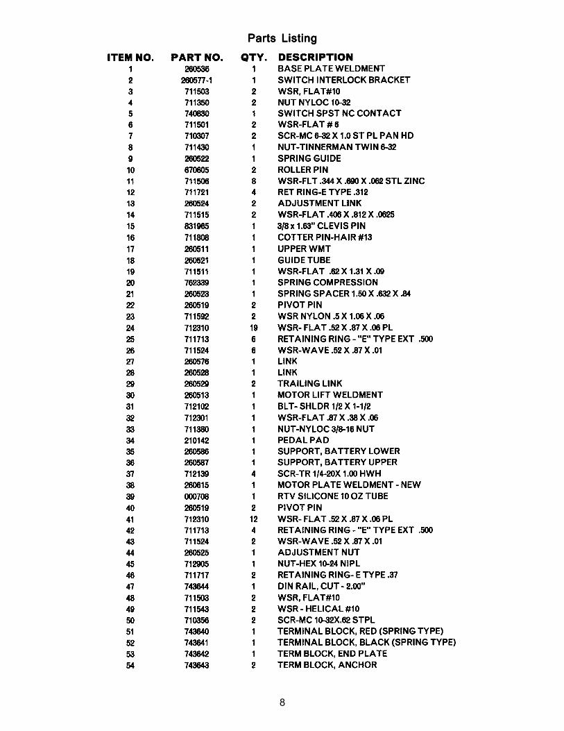
Parts ListingParts ListingParts ListingParts ListingParts Listing
9
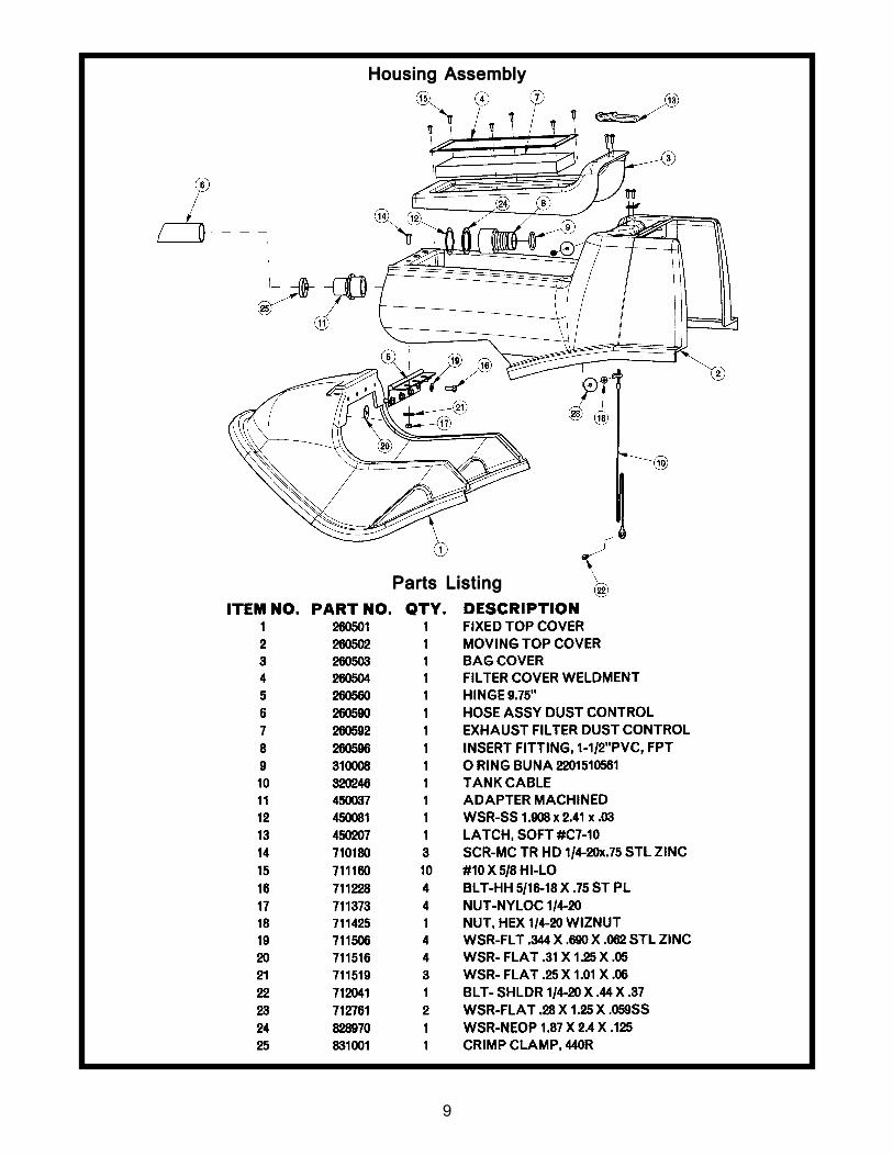
Parts ListingParts ListingParts ListingParts ListingParts Listing
Housing Housing Housing Housing Housing AssemblyAssemblyAssemblyAssemblyAssembly
10
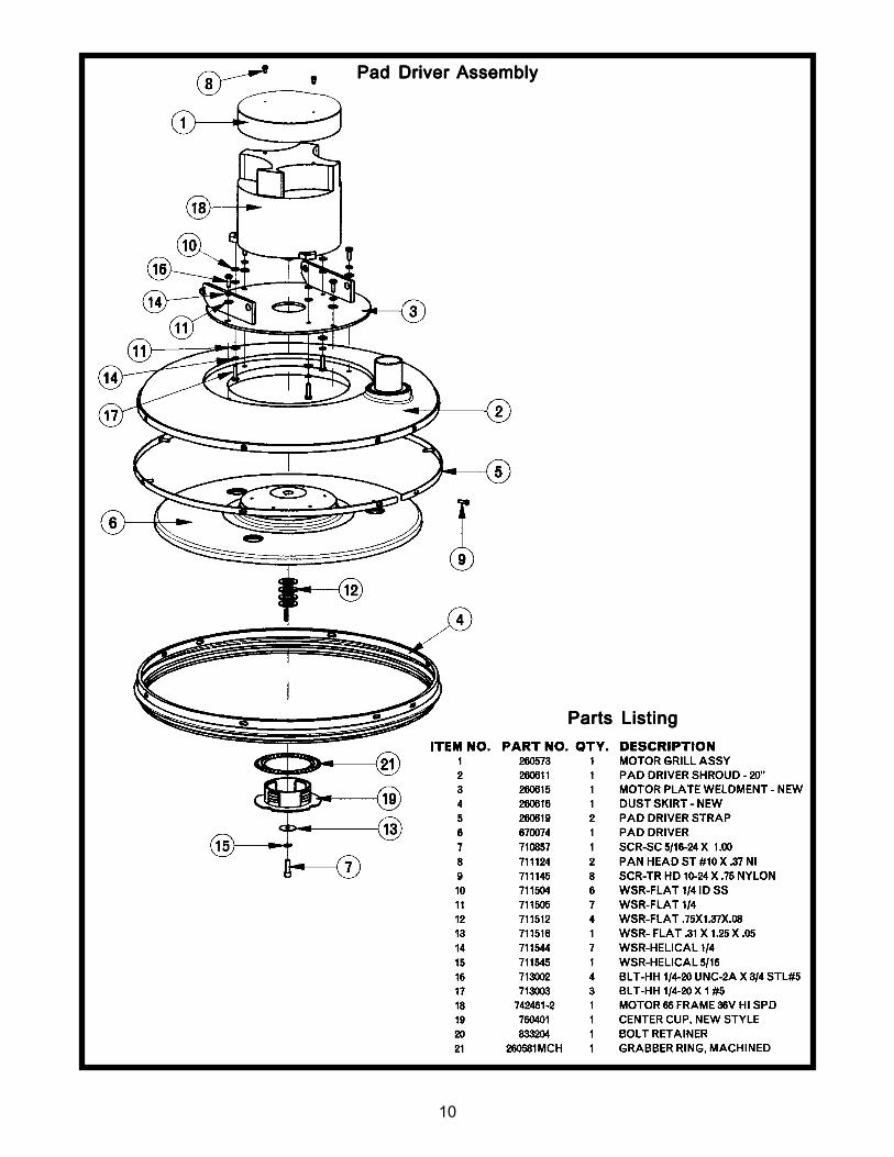
Parts ListingParts ListingParts ListingParts ListingParts Listing
Pad Driver Pad Driver Pad Driver Pad Driver Pad Driver AssemblyAssemblyAssemblyAssemblyAssembly
11
Parts ListingParts ListingParts ListingParts ListingParts Listing
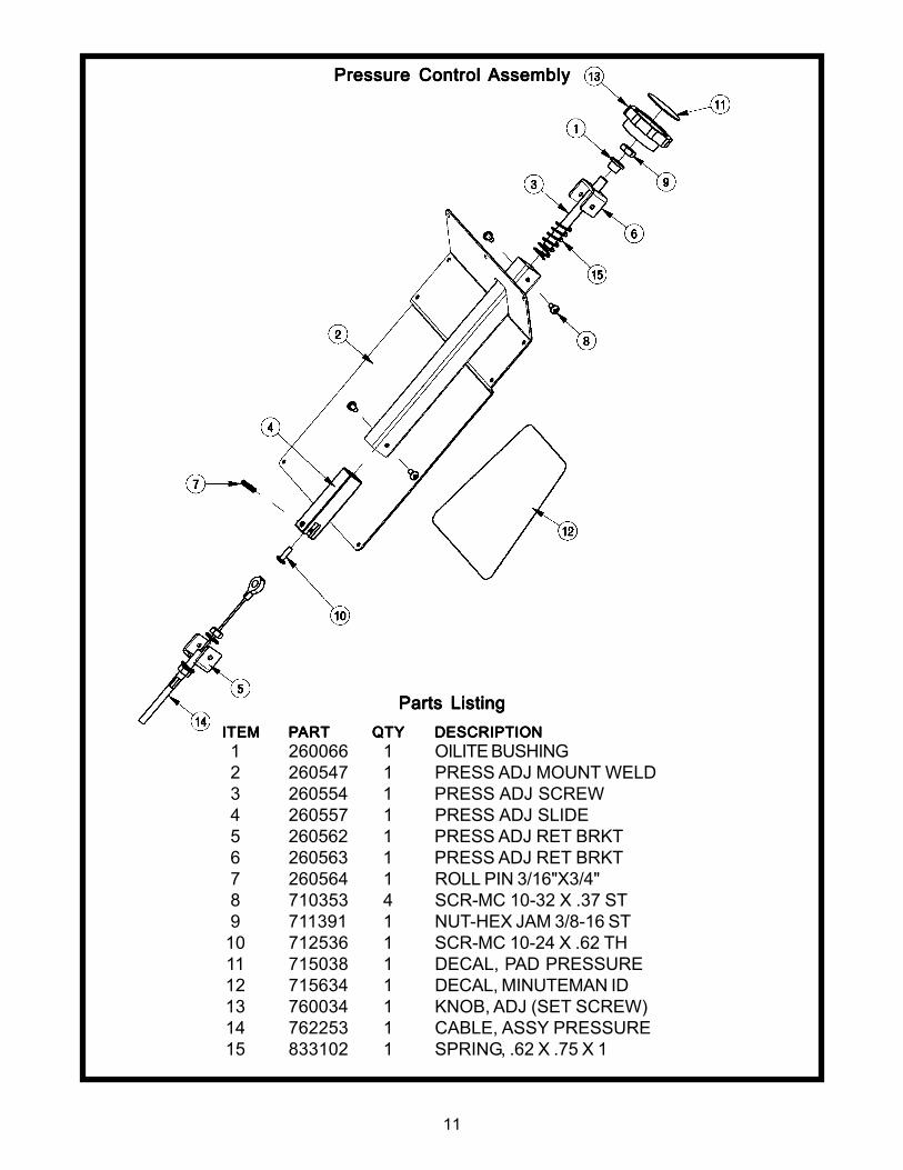
Pressure Control Pressure Control Pressure Control Pressure Control Pressure Control AssemblyAssemblyAssemblyAssemblyAssembly
ITEMITEMITEMITEMITEM PPPPPARARARARARTTTTT QTYQTYQTYQTYQTY DESCRIPTIONDESCRIPTIONDESCRIPTIONDESCRIPTIONDESCRIPTION1 260066 1 OILITE BUSHING2 260547 1 PRESS ADJ MOUNT WELD3 260554 1 PRESS ADJ SCREW4 260557 1 PRESS ADJ SLIDE5 260562 1 PRESS ADJ RET BRKT6 260563 1 PRESS ADJ RET BRKT7 260564 1 ROLL PIN 3/16"X3/4"8 710353 4 SCR-MC 10-32 X .37 ST9 711391 1 NUT-HEX JAM 3/8-16 ST
10 712536 1 SCR-MC 10-24 X .62 TH11 715038 1 DECAL, PAD PRESSURE12 715634 1 DECAL, MINUTEMAN ID13 760034 1 KNOB, ADJ (SET SCREW)14 762253 1 CABLE, ASSY PRESSURE15 833102 1 SPRING, .62 X .75 X 1
12
Parts ListingParts ListingParts ListingParts ListingParts Listing
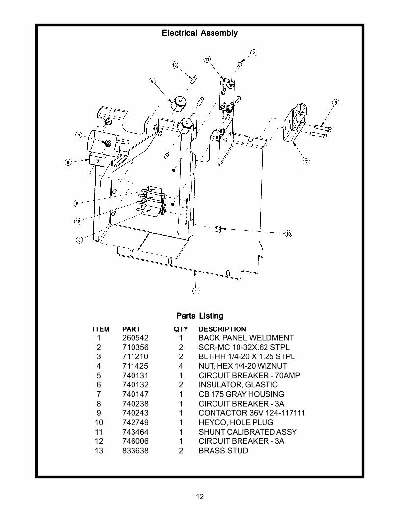
Electrical Electrical Electrical Electrical Electrical AssemblyAssemblyAssemblyAssemblyAssembly
ITEMITEMITEMITEMITEM PPPPPARARARARARTTTTT QTYQTYQTYQTYQTY DESCRIPTIONDESCRIPTIONDESCRIPTIONDESCRIPTIONDESCRIPTION1 260542 1 BACK PANEL WELDMENT2 710356 2 SCR-MC 10-32X.62 STPL3 711210 2 BLT-HH 1/4-20 X 1.25 STPL4 711425 4 NUT, HEX 1/4-20 WIZNUT5 740131 1 CIRCUIT BREAKER - 70AMP6 740132 2 INSULATOR, GLASTIC7 740147 1 CB 175 GRAY HOUSING8 740238 1 CIRCUIT BREAKER - 3A9 740243 1 CONTACTOR 36V 124-117111
10 742749 1 HEYCO, HOLE PLUG11 743464 1 SHUNT CALIBRATED ASSY12 746006 1 CIRCUIT BREAKER - 3A13 833638 2 BRASS STUD
13
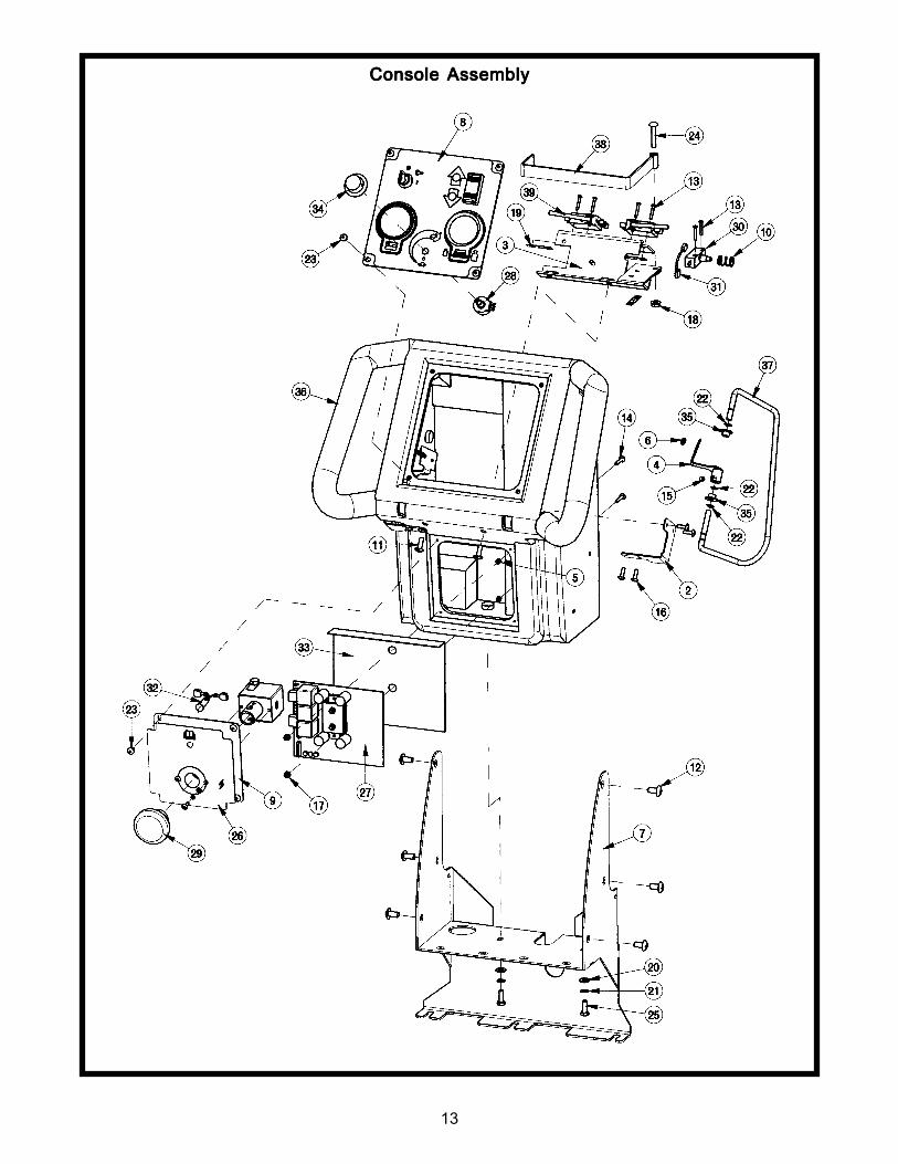
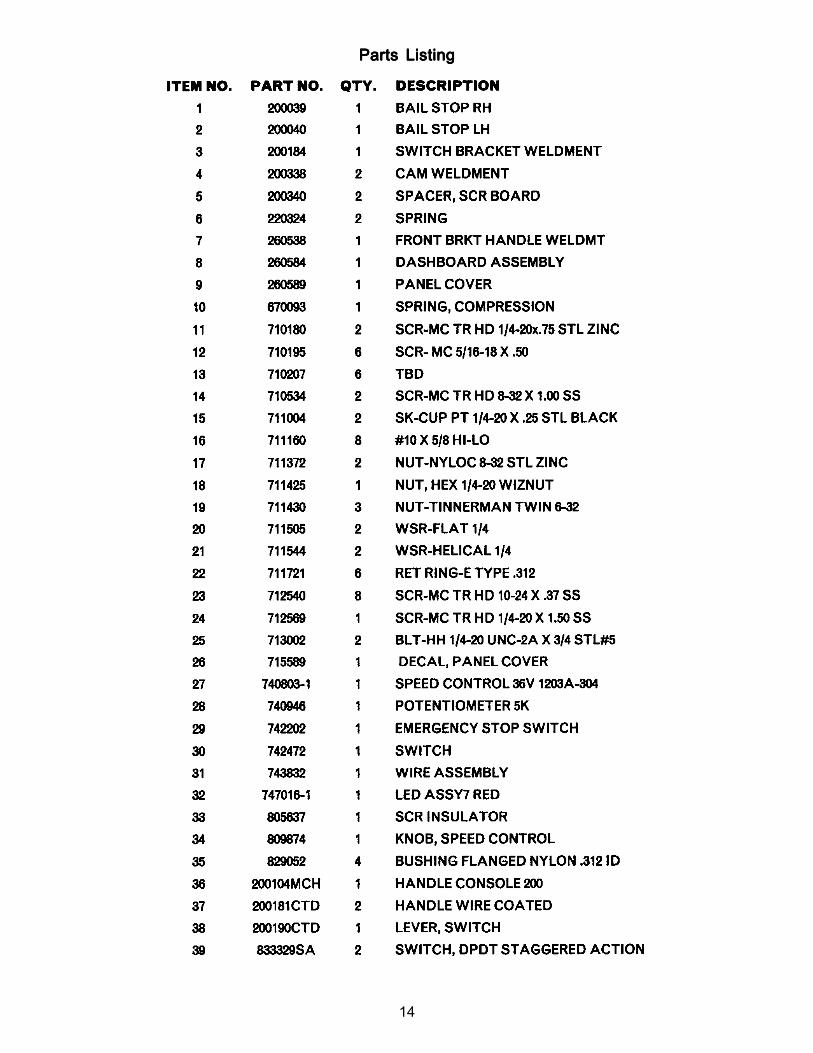
Console Console Console Console Console AssemblyAssemblyAssemblyAssemblyAssembly
14
Parts ListingParts ListingParts ListingParts ListingParts Listing
15
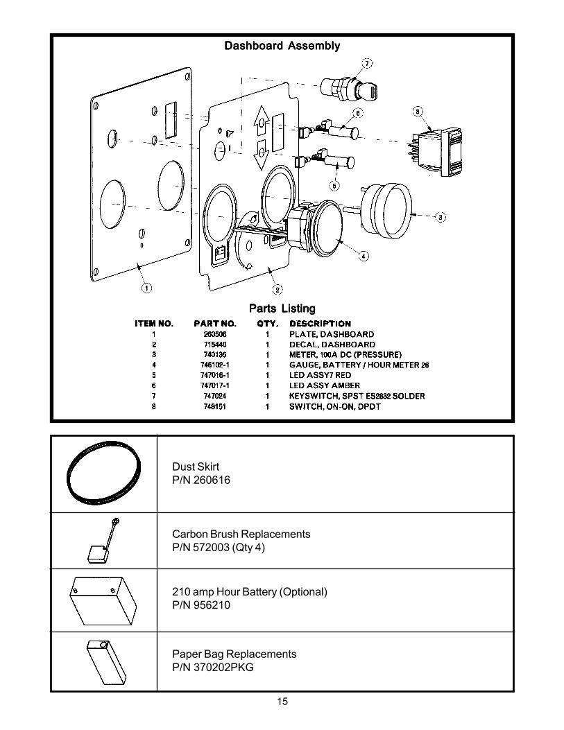
Dust SkirtP/N 260616
210 amp Hour Battery (Optional)P/N 956210
Carbon Brush ReplacementsP/N 572003 (Qty 4)
Paper Bag ReplacementsP/N 370202PKG
Parts ListingParts ListingParts ListingParts ListingParts Listing
Dashboard Dashboard Dashboard Dashboard Dashboard AssemblyAssemblyAssemblyAssemblyAssembly
16
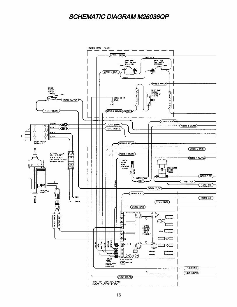
SCHEMASCHEMASCHEMASCHEMASCHEMATIC DIAGRAM M26036QPTIC DIAGRAM M26036QPTIC DIAGRAM M26036QPTIC DIAGRAM M26036QPTIC DIAGRAM M26036QP
17
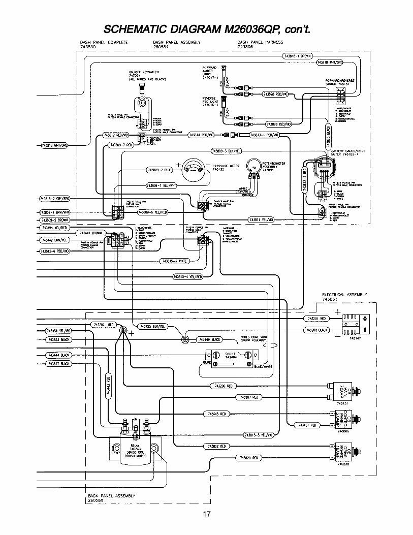
SCHEMASCHEMASCHEMASCHEMASCHEMATIC DIAGRAM M26036QPTIC DIAGRAM M26036QPTIC DIAGRAM M26036QPTIC DIAGRAM M26036QPTIC DIAGRAM M26036QP, con’t., con’t., con’t., con’t., con’t.
18
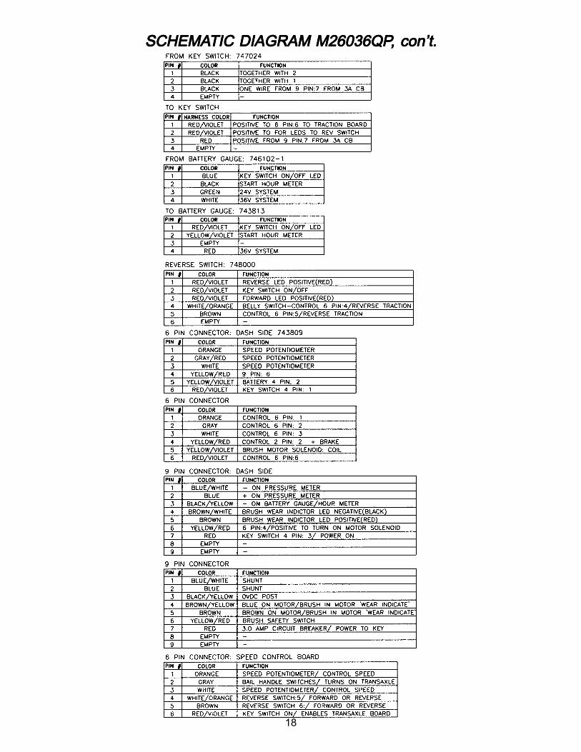
SCHEMASCHEMASCHEMASCHEMASCHEMATIC DIAGRAM M26036QPTIC DIAGRAM M26036QPTIC DIAGRAM M26036QPTIC DIAGRAM M26036QPTIC DIAGRAM M26036QP, con’t., con’t., con’t., con’t., con’t.
LIMITED WLIMITED WLIMITED WLIMITED WLIMITED WARRANTYARRANTYARRANTYARRANTYARRANTY
Minuteman International, Inc. warrants to the original purchaser/user that this product is free from defects in workmanship andmaterials under normal use and service for a period of three years from date of purchase. In addition, Minuteman International,Inc. will, at its option, honor labor warranty claims for the first 12 months from date of sale, provided such claims are submittedthrough and approved by factory authorized repair stations. Minuteman International, Inc. will, at its option, repair or replacewithout charge, except for transportation costs, parts that fail under normal use and service when operated and maintained inaccordance with the applicable operation and instruction manuals.
This warranty does not apply to normal wear, or to items whose life is dependent on their use and care, such as belts, cords,switches, hoses, rubber parts, electrical motor components or adjustments. Parts not manufactured by Minuteman International,Inc. such as engines, batteries, battery chargers, hydraulic pumps, and tires are covered by and subject to the warranties and/or guarantees of their manufacturers. Please contact Minuteman International, Inc. for procedures in warranty claims againstthese manufacturers.
SSSSSpecial warning to purchaserpecial warning to purchaserpecial warning to purchaserpecial warning to purchaserpecial warning to purchaser — Use of replacement filters and/or prefilters not manufactured by Minuteman International, Inc.or its designated licensees, will void all warranties expressed or implied.
A potential health hazard exists without exact original equipment replacement.
All warranteed items become the sole property of Minuteman International, Inc. or its original manufacturer, whichever the casemay be.
Minuteman International, Inc. disclaims any implied warranty, including the warranty of merchantability and the warranty offitness for a particular purpose. Minuteman International, Inc. assumes no responsibility for any special, incidental or consequentialdamages.
This limited warranty is applicable only in the U.S.A. and Canada, and is extended only to the original user/purchaser of thisproduct. Customers outside the U.S.A. and Canada should contact their local distributor for export warranty policies. MinutemanInternational, Inc. is not responsible for costs or repairs performed by persons other than those specifically authorized by MinutemanInternational, Inc. This warranty does not apply to damage from transportation, alterations by unauthorized persons, misuse orabuse of the equipment, use of non-compatible chemicals, or damage to property, or loss of income due to malfunctions of theproduct.
If a difficulty develops with this machine, you should contact the dealer from whom it was purchased.
This warranty gives you specific legal rights, and you may have other rights which vary from state to state. Some states do notallow the exclusion or limitation of special, incidental or consequential damages, or limitations on how long an implied warrantylasts, so the above exclusions and limitations may not apply to you.
988172Rev. A 9/05
Printed in U.S.A.
World HeadquartersWorld HeadquartersWorld HeadquartersWorld HeadquartersWorld Headquarters Minuteman Canada, Inc.Minuteman International, Inc. 2210 Drew Road111 South Rohlwing Road Mississauga, OntarioAddison, Illinois 60101 L5S 1B1
PHONE: (630) 627-6900 PHONE: (905) 673-3222FAX (630) 627-1130 FAX (905) 673-5161www.minutemanintl.com
A Member of the Hako Group of Companies