Embed Size (px)
Citation preview

Launching the ENERGY STAR SSL ProgramSTAR SSL Program
Washington, DCMay 15, 2008
Derek GreenauerD&R International
Lumen Maintenance
IESNA LM 80 2008IESNA LM-80-2008
Kevin Dowling, PhD
Chairman, Testing Procedures SSL Committee
Oct. 30, 2008

WHY LM-80?
• We need to better determine true lifetimes of LED products
• StStanddards are needded to provid ide a consiisttentt an ddd d t common language for manufacturers and customers
• There is no commonly accepted criteria for lifetimeThere is no commonly accepted criteria for lifetime

e e s
The Beginningsg g
• ASSIST at the Lighting Research Center – ASSIST program – NNarenddran et all b began llookiki ng at liflifetiime iissues iin
2000-2001 – Current packagges, 5mm, had very poor longg termp y p
performance
– ASSIST program began developing guidelines and methods for determining lumen maintenancemethods for determining lumen maintenance.
– ASSIST Recommends: LED Life Testing, Vol 1-6, Lighting Research Center, RPI, Troy NY 2005.


eeded o e Sta Needed for Energy Stargy
• Chromaticity • Luminous Flux • Definitions • Lumen Maintenance

80 Co te ts
LM-80 Contents
• Scope • References • Definitions • Ambient and Physical Conditions
El t i l d Th l C diti• Electrical and Thermal Conditions • Test and Measurement Procedures • Lumen Maintenance Testing Method for LED Light Lumen Maintenance Testing Method for LED Light
Sources • Test Report
ScopeScope
• This document provides the methods of the measurement of lumen maintenance of source including sources including LED packages arrays including sources including LED packages, arrays and modules only
• This approved method does not pprovide guidance orpp g make any recommendations regarding predictive estimations or extrapolation for lumen maintenance beyond the limits of the lumen maintenancebeyond the limits of the lumen maintenance
determined from actual measurement

e t o s
t
Definitions
• Measurement Units • LED Light Source • Lumen Maintenance
– Luminous flux remaining output (typically expressed as a percentage of the max output) at any selecteda percentage of the max output) at any selected elapsed operating time.
– LED Light Source Failure R t d L M i t Lif (L = time to 70% LM) 70% LM)– Rated Lumen Maintenance Life (L70 ti
– Case Temperature

C diti
Ambient and Physical Conditions
• 4.1 General – Relatively clean environment
• 4.2 LED Unit Marking – Marking individual units
•• 4 3 Sample Selection 4.3 Sample Selection – Representative sampling to be reported
C diti
Ambient and Physical Conditions
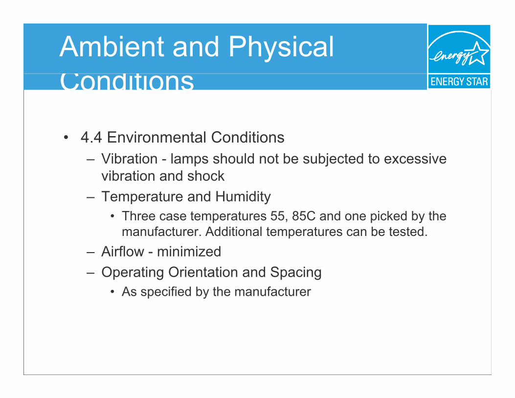
• 4.4 Environmental Conditions – Vibration - lamps should not be subjected to excessive
vibration and shockvibration and shock – Temperature and Humidity
• Three case temperatures 55, 85C and one picked by the manufacturer. Additional temperatures can be tested.
– Airflow - minimized – Operating Orientation and SpacingOperating Orientation and Spacing
• As specified by the manufacturer

C diti
Electrical and Thermal Conditions
• 5.1 Input Voltage and Current - ripple held to 2%
• 5.2 Line Voltage Waveshape - Within 3% • 5.3 Input Current Regulation - regulated within 3%
• 5.4 Auxiliary Equipment including Drivers – Per manufacturers guidance Per manufacturers guidance
• 5.5 Case Temperature

P d
Test & Measurement Procedures
• 6.1 Instrumentation – Elapsed time measured only when sources are energized
•• 6 2 Photometry Measurement 6.2 Photometry Measurement – In conformance with appropriate laboratory method under
test. E.g. LM-79 or other. Recommended that measurements use a spectroradiometer to collect color data as welluse a spectroradiometer to collect color data as well.
• 6.3 Photometry Measurement Temperature – 25C +/- 1C. Source shall cool to room temperature prior to
measurementmeasurement

T t M th d
Lumen Maintenance Test Method
• 7.1 Testing Duration and Interval – At least 6000 hours with data collection at a minumum of
every 1000 hours. 10000 hours preferred for improved predictive modeling.
• 7.2 Operating Cycle – Shall be driven at constant current
• 7.3 Recording Failures – Check for source failure through visual observation or
automatic monitoring • 7.4 CChromaticity
– Measured and reported

est t
Test Reportepo1. Number of LED Light Sources tested 22. Description of LED light sources Description of LED light sources 3. Description of auxiliary equipment 4. Operating cycle 5 Ambient conditions including airflow Ambient conditions including airflow, temperature & humidity5. temperature & humidity 6. Test point temperature 7. Drive current 88. I iti l l i fl d f d lt t tInitial luminous flux and forward voltage at current 9. Lumen maintenance data for each LED light source (median,
std deviation, min, max LM values for all the LED light sources 10 Observations of LED light source failures including failure 10. Observations of LED light source failures including failure
conditions and time of failure 11. LED light source monitoring interval 12 Photometric measurement uncertainty 12. Photometric measurement uncertainty 13. Chromaticity shift reported over the measurement time

TM-21
• Extrapolation and Prediction additions • In process and in committee

LM-80 Next Steps
Use LM-80 to gather significant amount of data to provide input into the prediction process and, eventually, foldprediction and extrapolation into LM-80prediction and extrapolation into LM 80
Further information requested from users and l blaboratoriies as LM-80 i 80 is used.LM d
THANK YOU!THANK YOU!

Launching the ENERGY STAR SSL ProgramSTAR SSL Program
Washington, DCMay 15, 2008
Derek GreenauerD&R International
ENERGY STAR® Webinar:
Requirements for Lumen Requirements for Lumen
Maintenance
J ff M C ll h LC
Jeff McCullough, LC
Pacific Northwest National Laboratory
Oct 30 2008Oct. 30, 2008
Agenda
1. In-situ Testing Requirement and ANSI/UL 1598/153
2. The Temperature Measurement Point (TMP) 3. Application of LM-80 test data 4. Example 5 S bSubmissiion Requiirementts5. i R

t
t
In Situ Testing Requirement
• LM 80 2008 i ( k dLM-80-2008 is a component (package, modulle or array) level test
• Lumen deppreciation ((Life)) determined byy in-situ temperature measurements of: – Package, Module or Array – Power Supply/DriverPower Supply/Driver
• Testing may be conducted at the same time as UL 1598/153
• T t d t d b N i ll R i d T ti Tests conducted by Nationally Recognized TestingLaboratories (NRTLs), recognized as qualified by OSHA

Approved Testing Laboratories
DOE will accept UL 1598 or UL 153 testing and certification from UL, UL signatories or the following NRTLs:
• Canadian Standards Association ((CSA);); • Intertek Testing Services NA, Inc. (ITSNA); • MET Laboratories, Inc. (MET); • NSF International (NSF);NSF International (NSF); • SGS U.S. Testing Company, Inc. (SGSUS); • TUV America, Inc. (TUVAM); • TUV Product Services GmbH (TUVPSG);TUV Product Services GmbH (TUVPSG); • TUV Rheinland of North America, Inc. (TUV); • Underwriters Laboratories Inc.(UL); and
•• Wyle Laboratories Inc (WL) Wyle Laboratories, Inc. (WL).

t t t t
Temperature Measurement Point (TMP)
• M f d i d TMP l i LM 80Manufacturer designated TMP correlating to LM-80 test report or power supply warranty – Module/ArrayModule/Array
• Solder Joint Temperature Ts
• Case Temperature Tc
• Board Temperature T Board Temperature Tb
– Power Supply • Case Temperature Tc
• Could also be Tb for integral
Power Supplies

UL 1598 Environments

UL 1598 Environments
Luminaire Types Mounting Orientation
Horizontal Vertical
S fSurface
Surface Section 19.10 Section 19.11
Surface-mounted under-cabinet Section 19.12
Suspended No apparatus required except if in situ mounting is ≤ 4" from the surface in g which case mount to Section 19.10 defined apparatus
Freestanding No apparatus required
Recessed
Non ICNon-IC Section 19 13 Section 19.13 Section 19 13 except without insulation Section 19.13 except without insulation
IC Section 19.15 Section 19.15

UL 1598 Test Apparatuses
Operating Hours
(hr)
Relative Light Output (%)
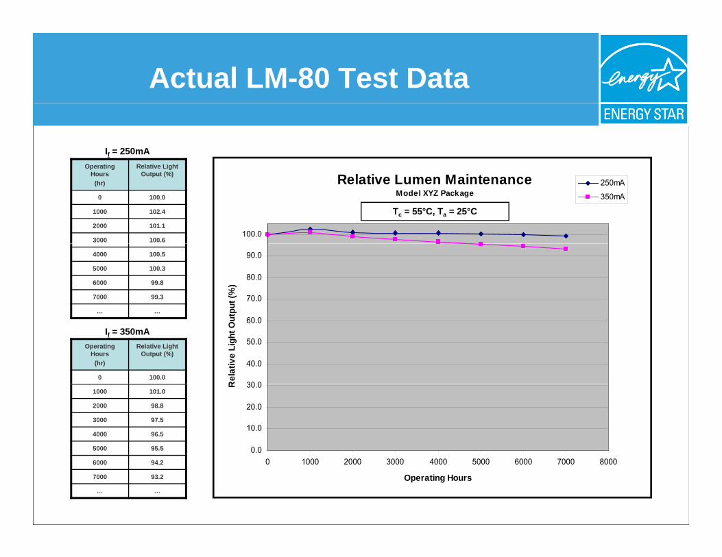
0 100.0
1000 101.0
2000 98.8
3000 97.5
4000 96.5
5000 95.5
6000 94.2
7000 93.2
… …
Actual LM-80 Test Data
Operating Hours
Relative Light Output (%)
If = 250mA
Hours (hr)
Output (%)
0 100.0
1000 102.4
2000 101.1
3000 100.6
Relative Lumen Maintenance Model XYZ Package
100.0
250mA
350mA
Tc = 55°C, Ta = 25°C
4000 100.5
5000 100.3
6000 99.8
7000 99.3
… …
70.0
80.0
90.0
put (
%)
30 0
40.0
50.0
60.0
Rel
ativ
e Li
ght O
ut
0.0
10.0
20.0
30.0R
0 1000 2000 3000 4000 5000 6000 7000 8000
Operating Hours
If = 350mA

Linear vs. Exponential Data
Rectangular Coordinates
90
100
Exp L70 25K
Linear
Log X - Linear Y
95
100 Exp L70 25K Linear
50
60
70
80
Ligh
t Out
put (
%) Exp L70 35K
75
80
85
90
ght O
utpu
t (%
)
Exp L70 35K
10
20
30
40
Rel
;act
ive
L
55
60
65
70
Rel
ativ
e Li
g 0
0 10 20 30 40 50 60 70 80 90 100
Thousands Hours
50 1 1000 1000000
Hours

–
Lumen Depreciation “Passing” Criteria
The luminaire PASSES the Lumen Deppreciation requirements if:
• The LM-80 test report for the package array or The LM 80 test report for the package, array or
module demonstrates lumen maintenance of:
– ≥ 91.8% (indoor residential) – ≥≥ 94 1% (outdoor residential and all commercial)94.1% (outdoor residential and all commercial)
• Measured during the in-situ temperature
measurement test (UL1598/153), at the hottest
TMP evaluated at ≥ 6 000 hours TMPLED, evaluated at ≥ 6,000 hours. • The drive current measured in the fixture is less than
or equal to the drive current specified in the LM-80 test report.

Application of LM-80 Data
IESNA LM-80 Test ReportModel XYZ PackageModel XYZ Package
100.0
90.0
utpu
t (%
)
70.0
80.0
elat
ive
Ligh
t Ou
60.0
Re 250mA
350mA
Linear
Exp 25K L70
Exp 35K L70
50.0 0 1000 2000 3000 4000 5000 6000 7000 8000
Operating Hours
Exp 35K L70
99.8
94.2
Operating Hours
Relative Light Output (%) Hours
(hr) Output (%)
0 100.0
1000 102.4
2000 101.1
3000 100.6
Relative Lumen Maintenance Model XYZ Package
4000 100.5
5000 100.3
6000
7000 99.3
… …
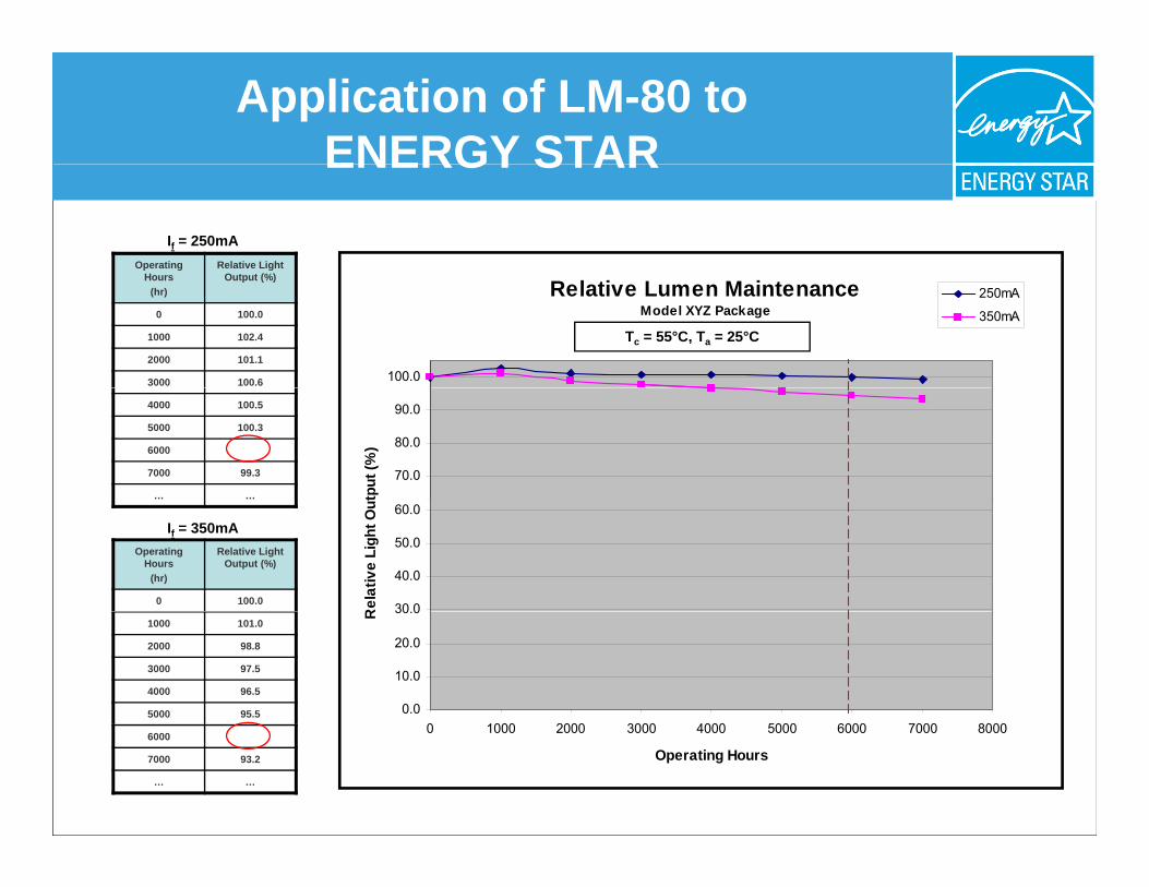
Application of LM-80 to ENERGY STARENERGY STAR
If = 250mA
100.0
250mA
350mA Tc = 55°C, Ta = 25°C
70.0
80.0
30 0
40.0
50.0
60.0 If = 350mA
0.0
10.0
20.0
30.0
0 1000 2000 3000 4000 5000 6000 7000 8000
Operating Hours
0 1000 2000 3000 4000 5000 6000 7000 8000
90.0
RRel
ativ
e Li
ght O
uttpu
t (%
)
Operating Hours
(hr)
Relative Light Output (%)
0 100.0
1000 101.0
2000 98.8
3000 97.5
4000 96.5
5000 95.5
6000
7000 93.2
… …

Application of LM-80 to ENERGY STARENERGY STAR
SCENARIO 1 The in situ measured TMPLED is greater than the highest case temperaturecollected according to LM-80 procedures. In this case the product cannotbe qqualified as there is no test data to substantiate manufacturer claims.
SCENARIO 2 The in situ measured TMPLED is less than the lowest case temperaturemeasured collected according to LMmeasured collected according to LM-80 procedures 80 procedures. In this case the In this case the product must use the data from the lowest case temperature measured according to LM-80 procedures.
SCENARIO 3SCENARIO 3 The in situ measured TMPLED is bounded above and below by casetemperature data collected according to LM-80 procedures. In this case linear interpolation shall be used to determine the lumen depreciation ((maintenance)) for the ppropposed pproduct.

Example
LM-80 Data for XYZ Package
100
101
Tc = 25°C
95
96
97
98
99
Out
put
Tc = 55°C
91
92
93
94
95
Rel
ativ
e Li
ght O
Tc = 67°C
Tc = 85°C
87
88
89
90
0 1000 2000 3000 4000 5000 6000 7000 8000 0 1000 2000 3000 4000 5000 6000 7000 8000
Hours

⎟⎜
Example Interpolation
LM-80 test data for XYZ Packagge
Case Temperature (Tc)
Time (hours) 25°C 55°C 85°C
0 100% 100% 100%
… … … …
6,000 99% 95% 90%
In situ measured TMP (TMPLED) = 67°C
90 95 ⎞⎛⎛ 90 − 95 ⎞LTMP = 95 + ⎜ ⎟((67 − 55))
⎝ 85 − 55 ⎠
∴LTMP = 93.0%
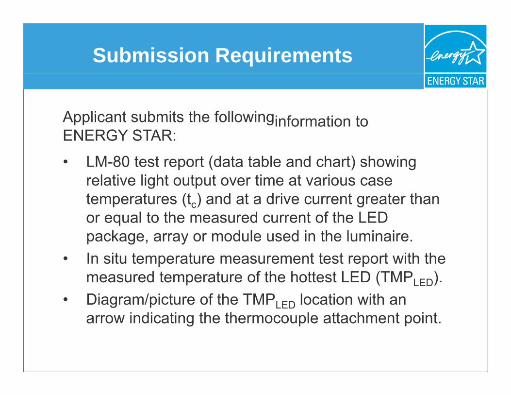
Submission Requirements
Applicant submits the followingg information topp ENERGY STAR:
• LM-80 test report (data table and chart) showing relative light output over time at various case temperatures (tc) and at a drive current greater than or equal to the measured current of the LEDor equal to the measured current of the LED package, array or module used in the luminaire.
• In situ temperature measurement test report with the measured td temperatture of the hhottest LED (TMP t LED (TMPLED)).f th tt
• Diagram/picture of the TMPLED location with an arrow indicating the thermocouple attachment point.arrow indicating the thermocouple attachment point.