Embed Size (px)
Citation preview
PARADIGM SPINEP
Dynamic Stabilization System
Lum
bar
Dyn
amic
Sta
bili
zati
on
2
Dynamic StabilizationDSSTM
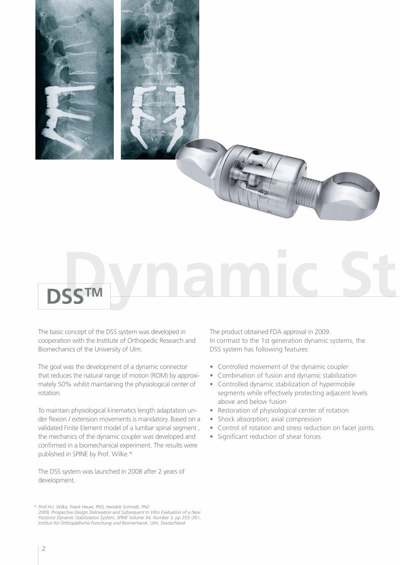
The basic concept of the DSS system was developed in cooperation with the Institute of Orthopedic Research and Biomechanics of the University of Ulm.
The goal was the development of a dynamic connector that reduces the natural range of motion (ROM) by approxi-mately 50% whilst maintaining the physiological center of rotation.
To maintain physiological kinematics length adaptation un-der flexion / extension movements is mandatory. Based on a validated Finite Element model of a lumbar spinal segment , the mechanics of the dynamic coupler was developed andconfirmed in a biomechanical experiment. The results were published in SPINE by Prof. Wilke.*
The DSS system was launched in 2008 after 2 years of development.
The product obtained FDA approval in 2009.In contrast to the 1st generation dynamic systems, the DSS system has following features:
• Controlledmovementofthedynamiccoupler• Combinationoffusionanddynamicstabilization• Controlleddynamicstabilizationofhypermobile segments while effectively protecting adjacent levels above and below fusion• Restorationofphysiologicalcenterofrotation• Shockabsorption;axialcompression• Controlofrotationandstressreductiononfacetjoints• Significantreductionofshearforces
* Prof.H-J. Wilke, Frank Heuer, PhD, Hendrik Schmidt, PhD 2009, Prospective Design Delineation and Subsequent In Vitro Evaluation of a New Posterior Dynamic Stabilization System, SPINE Volume 34, Number 3, pp 255–261, Institut für Orthopädische Forschung und Biomechanik, Ulm, Deutschland
3
Next generation dynamic stabilization
Dynamic Stabilization
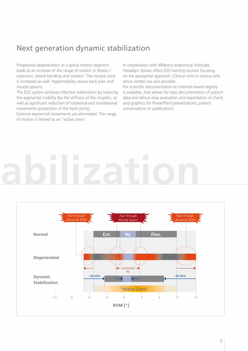
Progressive degeneration of a spinal motion segment leads to an increase of the range of motion in flexion / extension,lateralbendingandrotation.Theneutralzoneis increased as well. Hypermobility causes back pain and muscle spasms.TheDSSsystemachieveseffectivestabilizationbyreducingthe segmental mobility (by the stiffness of the coupler), as well as significant reduction of rotational and translational movements (protection of the facet joints).Extreme segmental movements are eliminated. The range ofmotionislimitedtoan“activezone”.
In cooperation with different anatomical institutesParadigm Spines offers DSS training courses focusing ontheparaspinalapproach.Clinicalvisitsinvariousrefe-rence centers are also possible.For scientific documentation an internet-based registry is available, that allows for easy documentation of patient data and allows easy evaluation and exportation of charts and graphics for PowerPoint presentations, patient conversations or publications.
Normal
Degenerated
Dynamic Stabilization
ı ı ı ı ı ı ı ı ı
-12 -9 -6 -3 0 3 6 9 12
Ext. Nz Flex.
IncreasedNZ
"Active Zone"
~30-50%~30-50%
ROM [º]
Pain through abnormal ROM
Pain through abnormal ROM
Pain through Muscle-Spasm
4
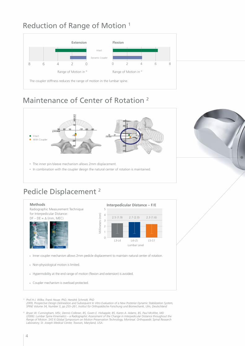
Maintenance of Center of Rotation 2
• The inner pin /sleeve mechanism allows 2mm displacement.
• In combination with the coupler design the natural center of rotation is maintained.
Intact
WithCoupler
1. Prof.H-J. Wilke, Frank Heuer, PhD, Hendrik Schmidt, PhD 2009, Prospective Design Delineation and Subsequent In Vitro Evaluation of a New Posterior Dynamic Stabilization System, SPINE Volume 34, Number 3, pp 255–261, Institut für Orthopädische Forschung und Biomechanik, Ulm, Deutschland
2. Bryan W. Cunningham, MSc, Dennis Colleran, BS, Gwen E. Holsapple, BS, Karen A. Adams, BS, Paul McAfee, MD (2006): Lumbar Spine Kinematics – a Radiographic Assessment of the Change in Interpedicular Distance throughout the Range of Motion. SAS 6 Global Symposium on Motion Preservation Technology, Montreal. Orthopaedic Spinal Research Laboratory, St. Joseph Medical Center, Towson, Maryland, USA.
Reduction of Range of Motion 1
02468 86420
Extension Flexion
Intact
DynamicCoupler
Range of Motion in ° Range of Motion in °
The coupler stiffness reduces the range of motion in the lumbar spine.
Pedicle Displacement 2
• Inner coupler mechanism allows 2mm pedicle displacement to maintain natural center of rotation.
• Non-physiological motion is limited.
• Hypermobility at the end range of motion (flexion and extension) is avoided.
• Couplermechanismisoverloadprotected.
MethodsRadiographic Measurement Techniquefor Interpedicular Distance: DF – DE = ∆(mm,MEC)
Interpedicular Distance – F/E5
4
3
2
1
0
Mill
imet
ers
(mm
)
2.5 (1.9) 2.7 (2.0) 2.3 (1.6)
Lumbar Level
L3-L4 L4-L5 L5-S1
A2
B2
C2
A1
B1
C1
Extension Flexion
5
Pain Relief•Controlleddynamicstabilizationofhypermobilesegments•Restorationofphysiologicalcenterofrotation•Shockabsorption;axialcompression•Controlofrotationandstressreductiononfacetjoints
Hybrid Solutions•Modularityofsystemallowscombinationoffusionand dynamicstabilization•Adjacentlevelsareeffectivelyprotected Ease of Use •Cannulatedscrewssupportminimallyinvasiveapplication•Paraspinalmusclesplittingtechniqueminimizesiatrogenic trauma•Easytouseinstrumentation
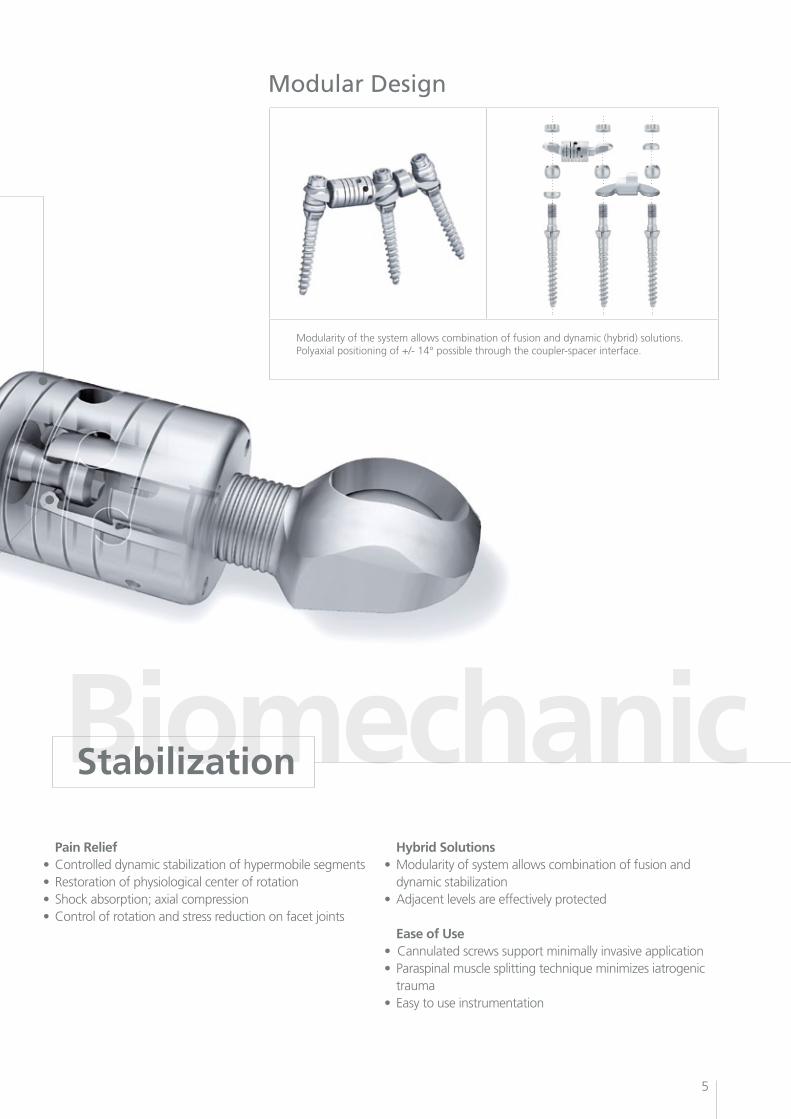
Modular Design
Modularity of the system allows combination of fusion and dynamic (hybrid) solutions. Polyaxial positioning of +/- 14° possible through the coupler-spacer interface.
Biomechanic Stabilization
Modular System
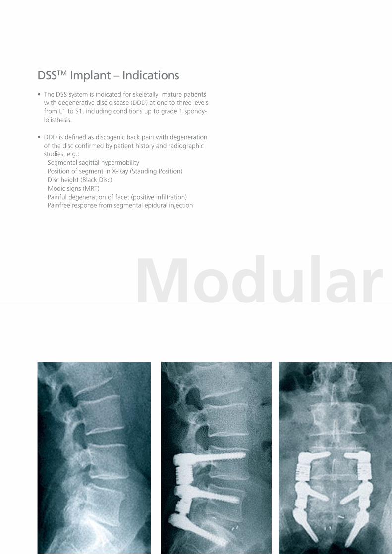
DSSTM Implant – Indications•TheDSSsystemisindicatedforskeletallymaturepatients with degenerative disc disease (DDD) at one to three levels from L1 to S1, including conditions up to grade 1 spondy- lolisthesis.
•DDDisdefinedasdiscogenicbackpainwithdegeneration of the disc confirmed by patient history and radiographic studies, e.g.: · Segmental sagittal hypermobility · Position of segment in X-Ray (Standing Position) · Disc height (Black Disc) · Modic signs (MRT) · Painful degeneration of facet (positive infiltration) · Painfree response from segmental epidural injection
7
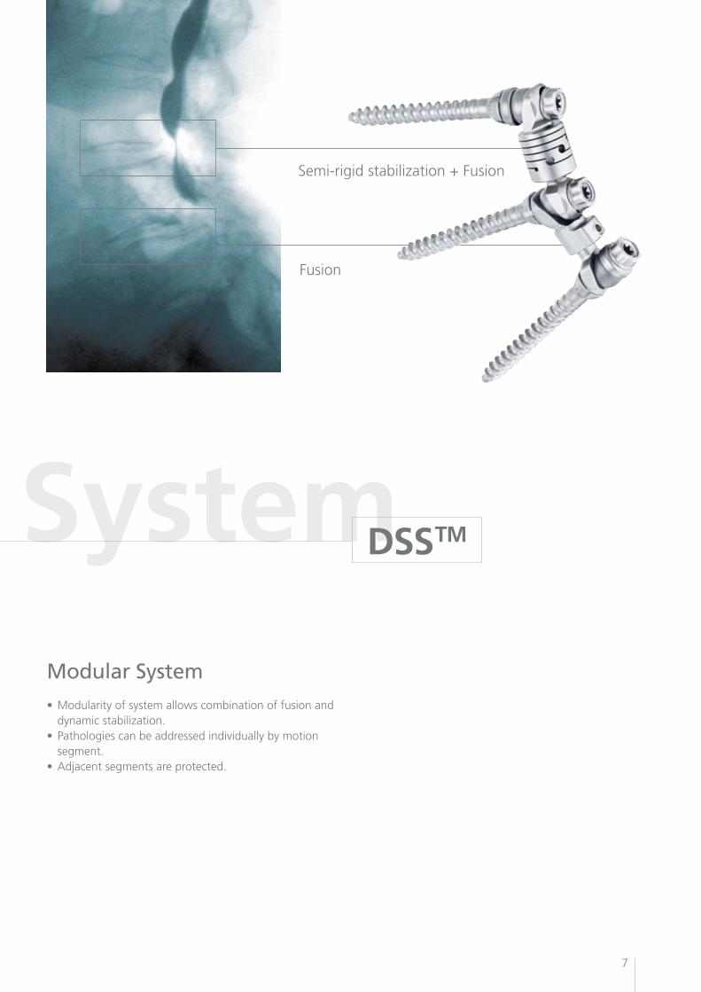
Modular System
DSSTM
Semi-rigidstabilization+Fusion
Fusion
Modular System•Modularityofsystemallowscombinationoffusionand dynamicstabilization.•Pathologiescanbeaddressedindividuallybymotion segment.•Adjacentsegmentsareprotected.
8
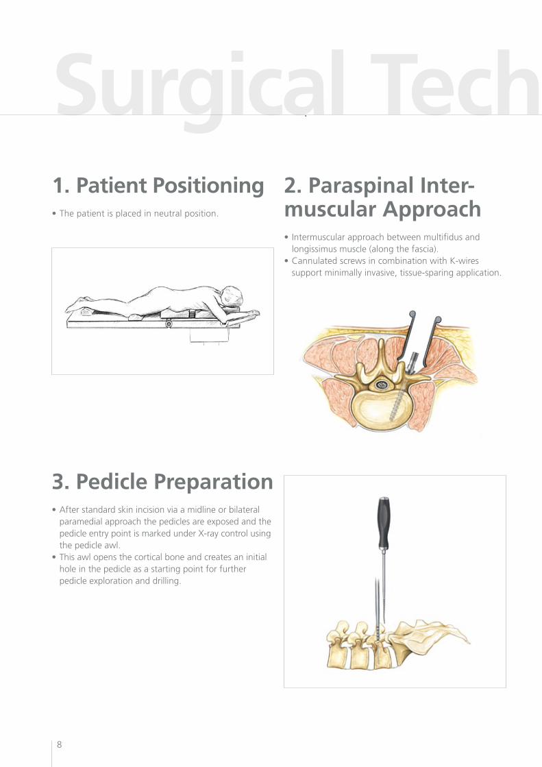
Surgical Technique 11. Patient Positioning•Thepatientisplacedinneutralposition.
2. Paraspinal Inter-muscular Approach• Intermuscularapproachbetweenmultifidusand longissimus muscle (along the fascia).•CannulatedscrewsincombinationwithK-wires support minimally invasive, tissue-sparing application.
3. Pedicle Preparation•Afterstandardskinincisionviaamidlineorbilateral paramedial approach the pedicles are exposed and the pedicle entry point is marked under X-ray control using the pedicle awl.•Thisawlopensthecorticalboneandcreatesaninitial hole in the pedicle as a starting point for further pedicle exploration and drilling.
9
Surgical Technique 1
DSSTM
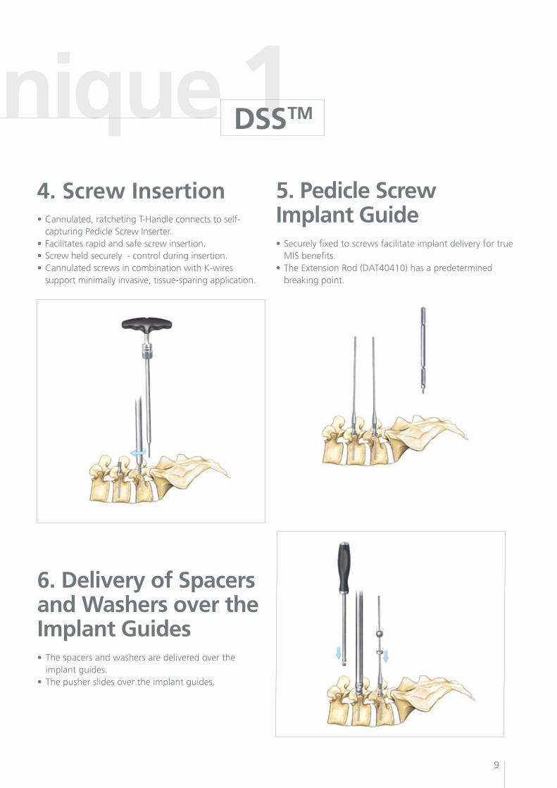
4. Screw Insertion•Cannulated,ratchetingT-Handleconnectstoself- capturing Pedicle Screw Inserter.•Facilitatesrapidandsafescrewinsertion.•Screwheldsecurely-controlduringinsertion.•CannulatedscrewsincombinationwithK-wires support minimally invasive, tissue-sparing application.
5. Pedicle Screw Implant Guide•Securelyfixedtoscrewsfacilitateimplantdeliveryfortrue MIS benefits.•TheExtensionRod(DAT40410)hasapredetermined breaking point.
6. Delivery of Spacersand Washers over the Implant Guides• Thespacersandwashersaredeliveredoverthe implant guides.• Thepusherslidesovertheimplantguides.
10
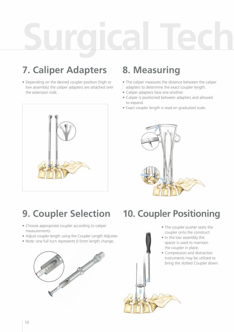
Surgical Technique 27. Caliper Adapters•Dependingonthedesiredcouplerposition(highor low assembly) the caliper adapters are attached over the extension rods.
8. Measuring•Thecalipermeasuresthedistancebetweenthecaliper adapters to determine the exact coupler length.•Caliperadaptersfaceoneanother.•Caliperispositionedbetweenadaptersandallowed to expand.•Exactcouplerlengthisreadongraduatedscale.
10. Coupler Positioning9. Coupler Selection•Chooseappropriatecoupleraccordingtocaliper measurements.•AdjustcouplerlengthusingtheCouplerLengthAdjuster.•Note:onefullturnrepresents0.5mmlengthchange.
•Thecouplerpusherseatsthe coupler onto the construct.• Inthelowassemblythe spacer is used to maintain the coupler in place.•Compressionanddistraction Instrumentsmaybeutilizedto bringtheslottedCouplerdown.
11
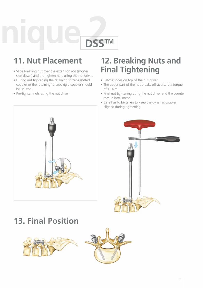
Surgical Technique 211. Nut Placement•Slidebreakingnutovertheextensionrod(shorter side down) and pre-tighten nuts using the nut driver. •Duringnuttighteningtheretainingforcepsslotted coupler or the retaining forceps rigid coupler should beutilized.•Pre-tightennutsusingthenutdriver.
12. Breaking Nuts and Final Tightening•Ratchetgoesontopofthenutdriver.•Theupperpartofthenutbreaksoffatasafetytorque of 12 Nm.•Finalnuttighteningusingthenutdriverandthecounter torque instrument.•Carehastobetakentokeepthedynamiccoupler aligned during tightening.
13. Final Position
DSSTM
12
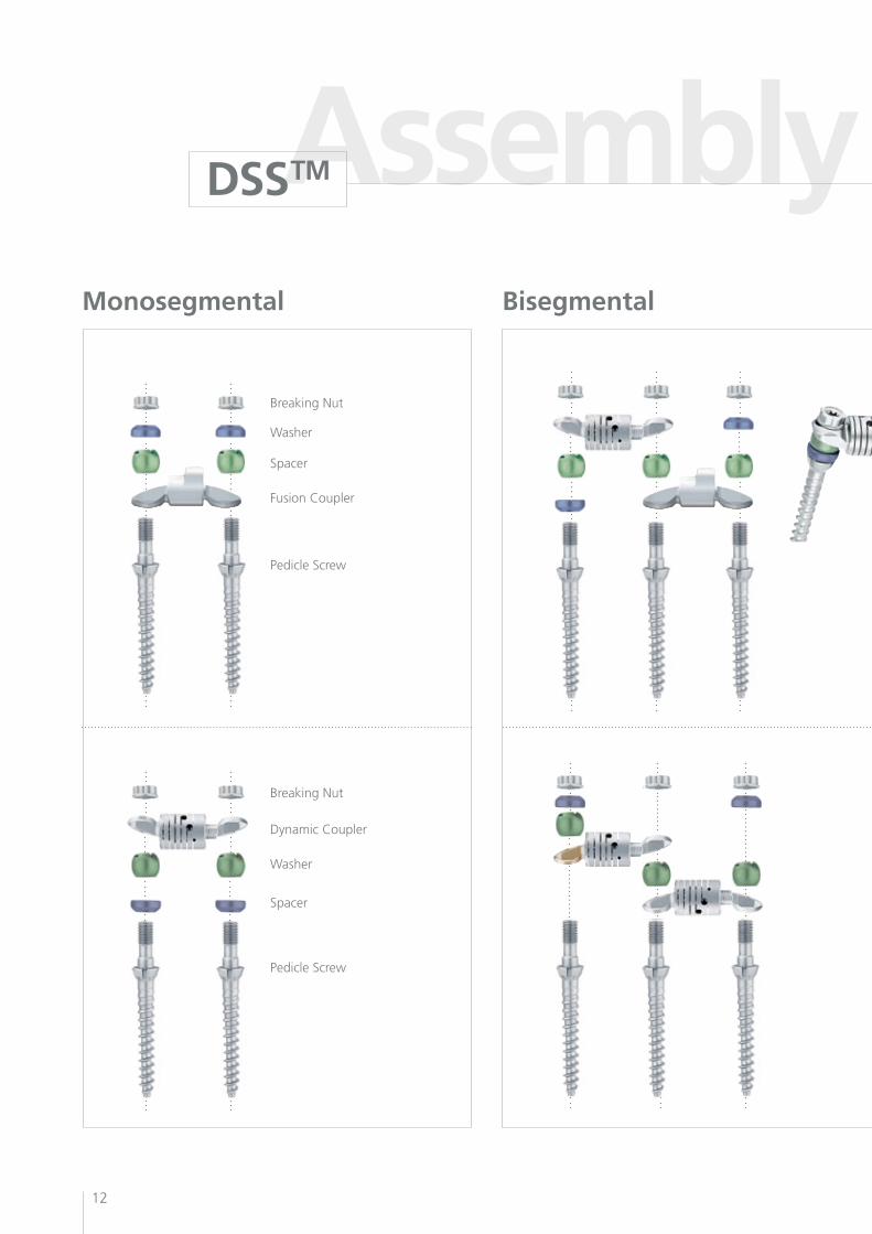
Assembly InstructionsMonosegmental Bisegmental
DSSTM
Breaking Nut
Breaking Nut
Washer
Spacer
Spacer
Washer
FusionCoupler
DynamicCoupler
Pedicle Screw
Pedicle Screw
13
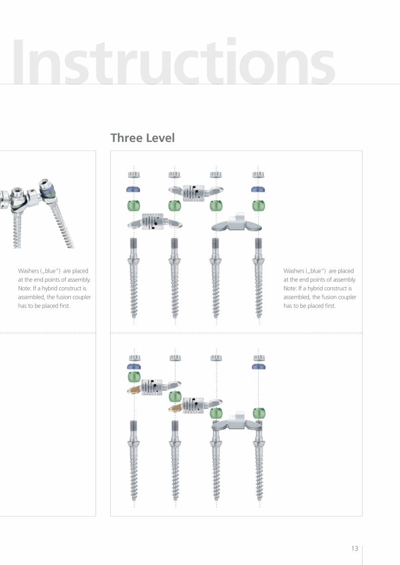
Assembly InstructionsThree Level
Washers („blue“) are placed
at the end points of assembly.
Note: If a hybrid construct is
assembled, the fusion coupler
has to be placed first.
Washers („blue“) are placed
at the end points of assembly.
Note: If a hybrid construct is
assembled, the fusion coupler
has to be placed first.
Patient CasesDSSTM
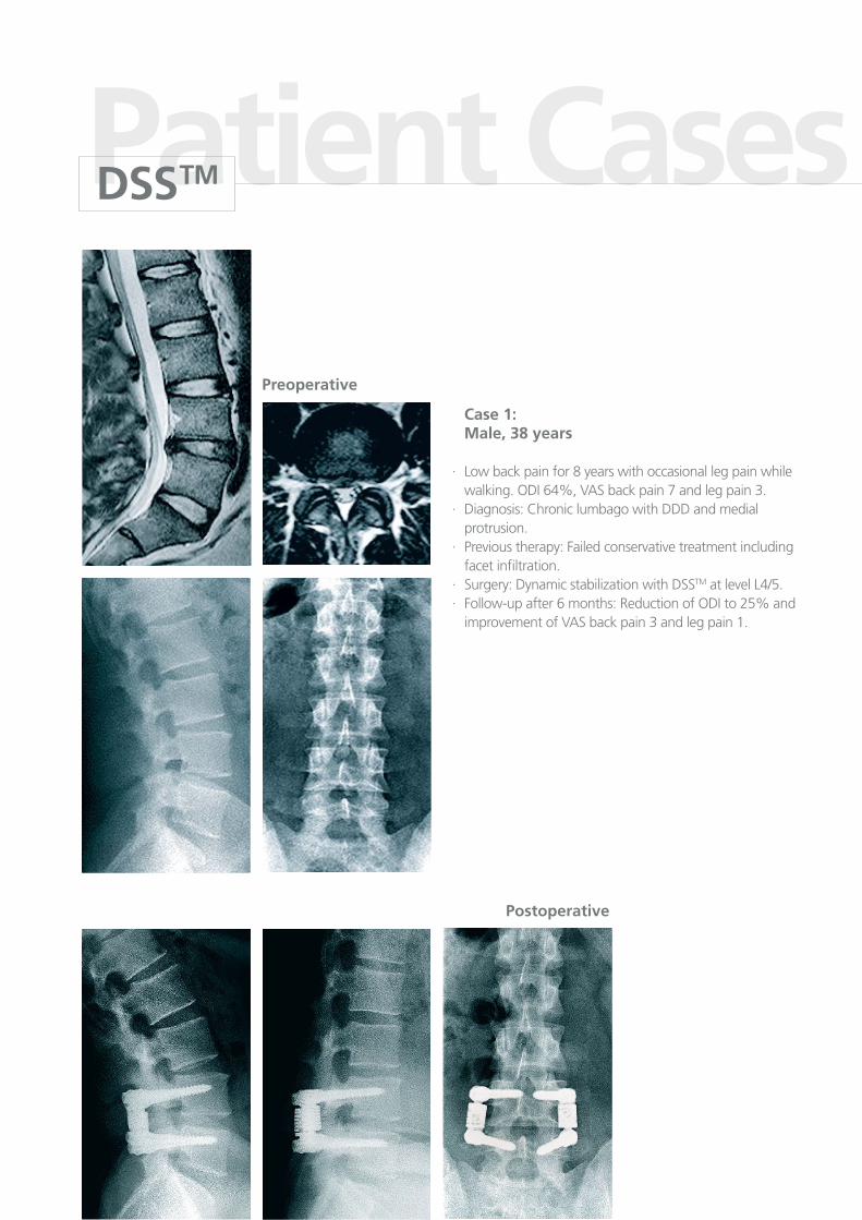
Case 1: Male, 38 years
· Low back pain for 8 years with occasional leg pain while walking. ODI 64%, VAS back pain 7 and leg pain 3.·Diagnosis:ChroniclumbagowithDDDandmedial protrusion.· Previous therapy: Failed conservative treatment including facet infiltration.·Surgery:DynamicstabilizationwithDSSTM at level L4/5.· Follow-up after 6 months: Reduction of ODI to 25% and improvement of VAS back pain 3 and leg pain 1.
Preoperative
Postoperative
15
Patient Cases
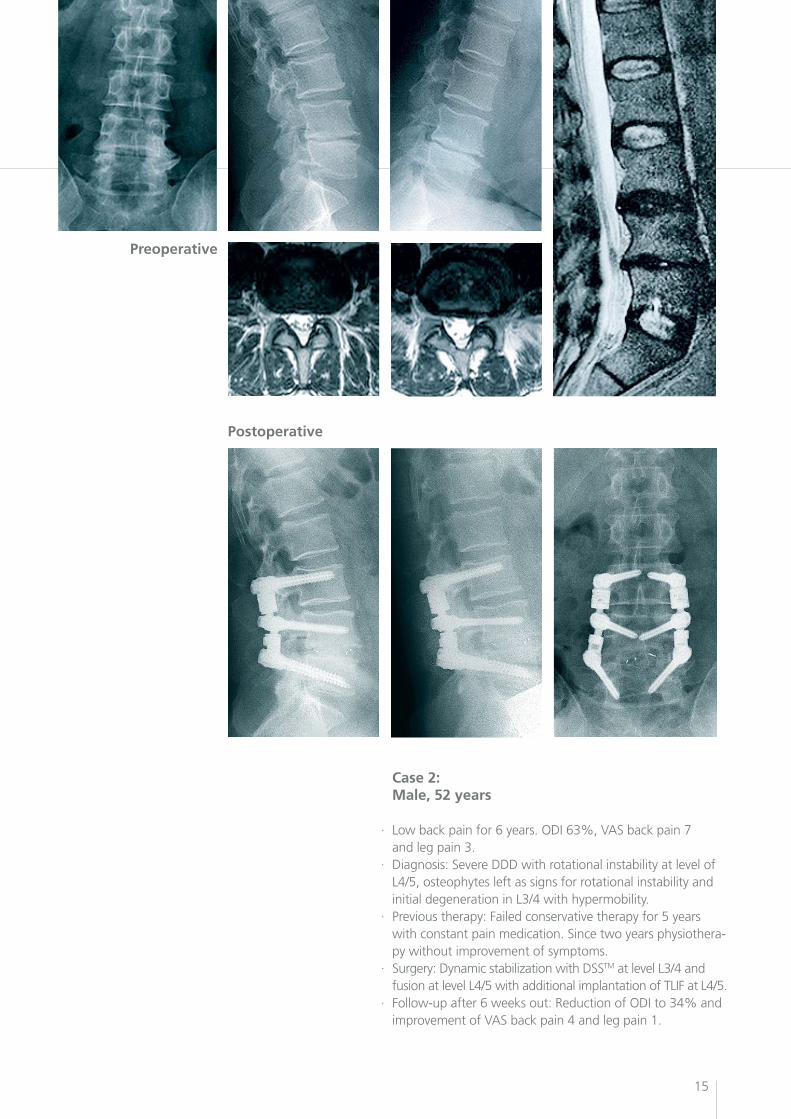
Case 2: Male, 52 years
· Low back pain for 6 years. ODI 63%, VAS back pain 7 and leg pain 3.· Diagnosis: Severe DDD with rotational instability at level of L4/5, osteophytes left as signs for rotational instability and initial degeneration in L3/4 with hypermobility.· Previous therapy: Failed conservative therapy for 5 years with constant pain medication. Since two years physiothera- py without improvement of symptoms.· Surgery:DynamicstabilizationwithDSSTM at level L3/4 and fusion at level L4/5 with additional implantation of TLIF at L4/5.· Follow-up after 6 weeks out: Reduction of ODI to 34% and improvement of VAS back pain 4 and leg pain 1.
Preoperative
Postoperative
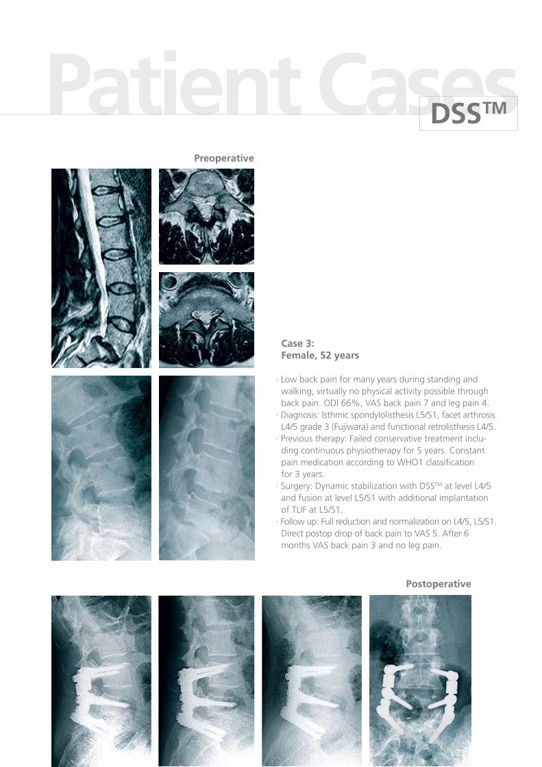
Case 3: Female, 52 years
· Low back pain for many years during standing and walking, virtually no physical activity possible through back pain. ODI 66%, VAS back pain 7 and leg pain 4.· Diagnosis: Isthmic spondylolisthesis L5/S1, facet arthrosis L4/5 grade 3 (Fujiwara) and functional retrolisthesis L4/5.· Previous therapy: Failed conservative treatment inclu- dingcontinuousphysiotherapyfor5years.Constant pain medication according to WHO1 classification for 3 years.·Surgery:DynamicstabilizationwithDSSTM at level L4/5 and fusion at level L5/S1 with additional implantation of TLIF at L5/S1.·Followup:FullreductionandnormalizationonL4/5,L5/S1. Direct postop drop of back pain to VAS 5. After 6 months VAS back pain 3 and no leg pain.
Preoperative
Postoperative
Patient CasesDSSTM
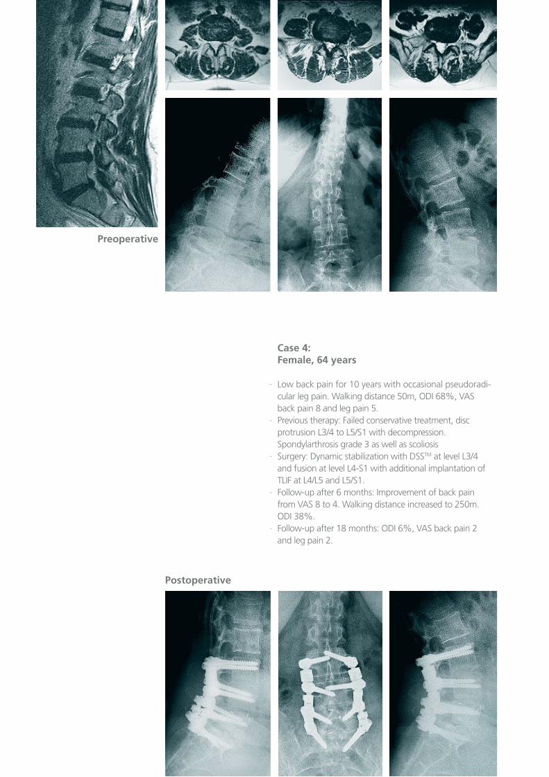
Case 4: Female, 64 years
· Low back pain for 10 years with occasional pseudoradi- cular leg pain. Walking distance 50m, ODI 68%, VAS back pain 8 and leg pain 5.· Previous therapy: Failed conservative treatment, disc protrusion L3/4 to L5/S1 with decompression. Spondylarthrosis grade 3 as well as scoliosis·Surgery:DynamicstabilizationwithDSSTM at level L3/4 and fusion at level L4-S1 with additional implantation of TLIF at L4/L5 and L5/S1. · Follow-up after 6 months: Improvement of back pain from VAS 8 to 4. Walking distance increased to 250m. ODI 38%.· Follow-up after 18 months: ODI 6%, VAS back pain 2 and leg pain 2.
Postoperative
Preoperative
Patient Cases
18
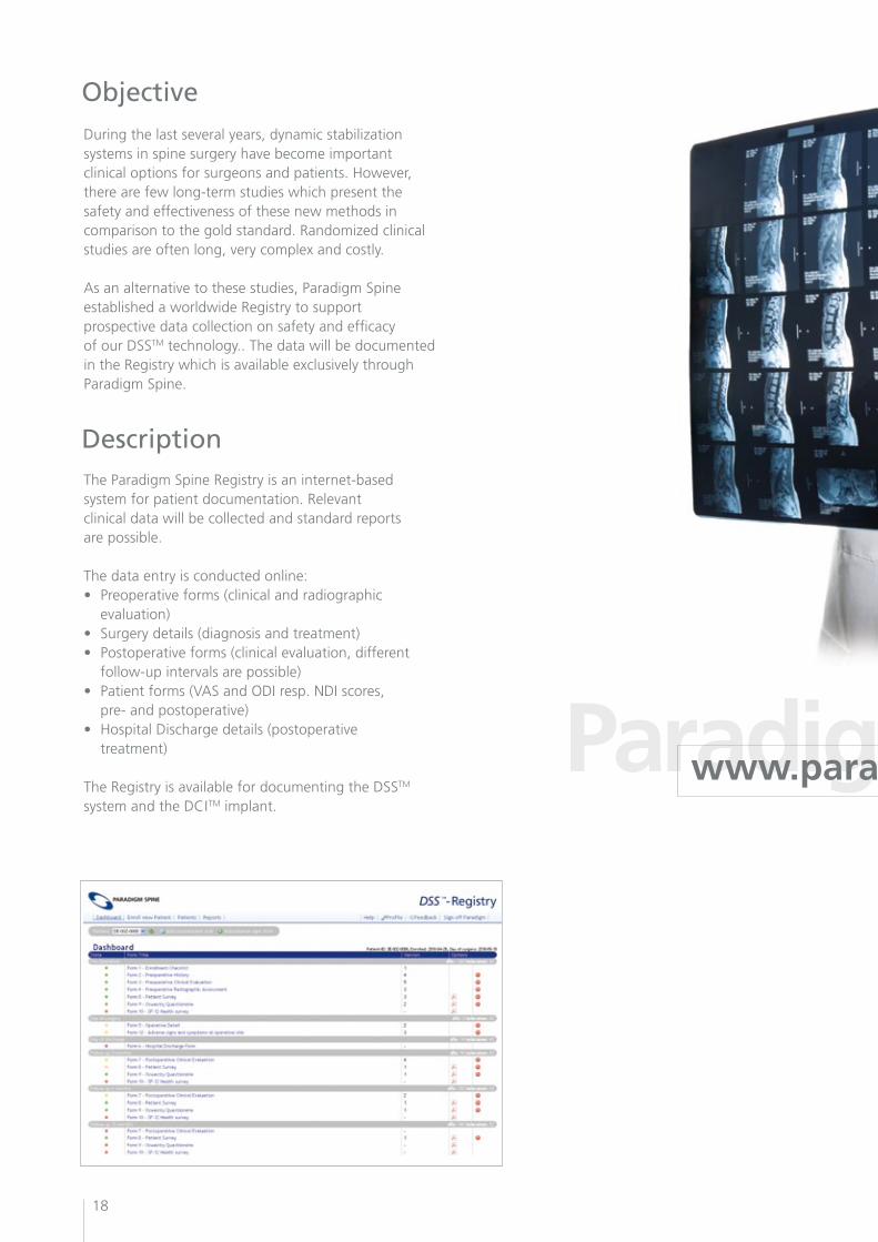
Objective
Description
Duringthelastseveralyears,dynamicstabilizationsystems in spine surgery have become important clinical options for surgeons and patients. However, there are few long-term studies which present the safety and effectiveness of these new methods in comparisontothegoldstandard.Randomizedclinicalstudies are often long, very complex and costly.
As an alternative to these studies, Paradigm Spine established a worldwide Registry to support prospective data collection on safety and efficacy of our DSSTM technology.. The data will be documented in the Registry which is available exclusively through Paradigm Spine.
The Paradigm Spine Registry is an internet-based system for patient documentation. Relevant clinical data will be collected and standard reports are possible.
The data entry is conducted online:• Preoperativeforms(clinicalandradiographic evaluation)• Surgerydetails(diagnosisandtreatment)• Postoperativeforms(clinicalevaluation,different follow-up intervals are possible)• Patientforms(VASandODIresp.NDIscores, pre- and postoperative)• HospitalDischargedetails(postoperative treatment)
The Registry is available for documenting the DSSTM systemandtheDCITM implant.
Paradigm Spine Registry www.paradigmspine.com/registry
19
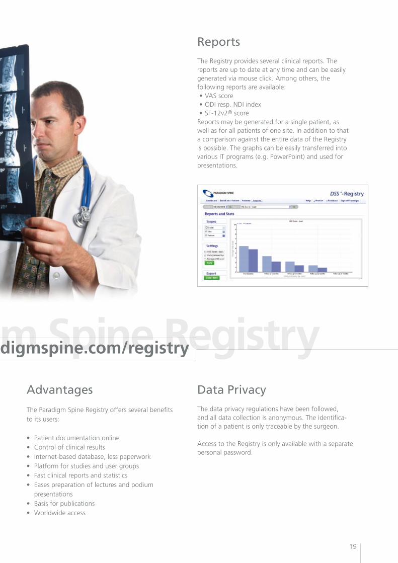
Reports
Data PrivacyAdvantages
The Registry provides several clinical reports. The reports are up to date at any time and can be easily generated via mouse click. Among others, the following reports are available:•VASscore•ODIresp.NDIindex•SF-12v2® scoreReports may be generated for a single patient, as well as for all patients of one site. In addition to that a comparison against the entire data of the Registry is possible. The graphs can be easily transferred into various IT programs (e.g. PowerPoint) and used for presentations.
The Paradigm Spine Registry offers several benefits to its users:
• Patient documentation online• Controlofclinicalresults• Internet-based database, less paperwork• Platform for studies and user groups• Fast clinical reports and statistics• Easespreparation of lectures and podium presentations • Basis for publications• Worldwide access
The data privacy regulations have been followed, and all data collection is anonymous. The identifica-tion of a patient is only traceable by the surgeon.
Access to the Registry is only available with a separate personal password.
Paradigm Spine Registry www.paradigmspine.com/registry
20
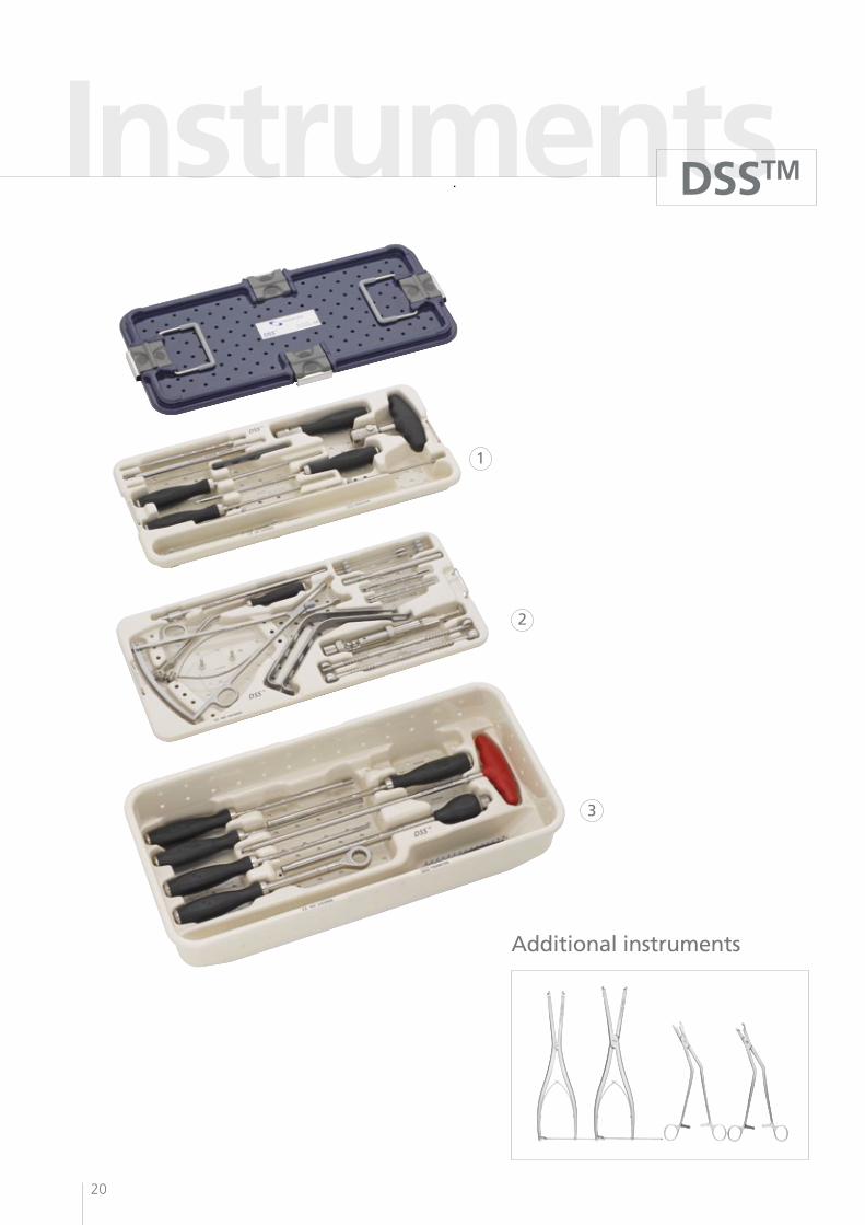
Instruments
DSSTM
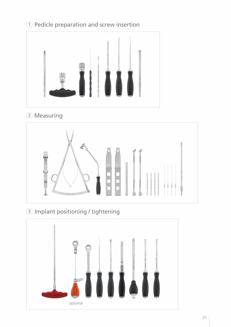
Additional instruments
2
3
1
21
Pedicle preparation and screw insertion
Measuring
Implant positioning / tightening
optional
2
3
1
22
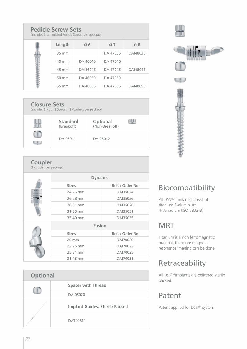
Pedicle Screw Sets(includes 2 cannulated Pedicle Screws per package)
Length ø 6 ø 7 ø 8
35 mm DAI47035 DAI48035
40 mm DAI46040 DAI47040
45 mm DAI46045 DAI47045 DAI48045
50 mm DAI46050 DAI47050
55 mm DAI46055 DAI47055 DAI48055
Closure Sets(includes 2 Nuts, 2 Spacers, 2 Washers per package)
Standard(Breakoff)
Optional (Non-Breakoff)
DAI06041 DAI06042
BiocompatibilityAll DSSTM implants consist of titanium 6-aluminium 4-Vanadium (ISO 5832-3).
MRTTitanium is a non ferromagnetic material, therefore magnetic resonance imaging can be done.
RetraceabilityAll DSSTM Implants are delivered sterile packed.
PatentPatent applied for DSSTM system.
Coupler (1 coupler per package)
Dynamic
Sizes Ref. / Order No.
24-26 mm DAI35024
26-28 mm DAI35026
28-31 mm DAI35028
31-35 mm DAI35031
35-40 mm DAI35035
Fusion
Sizes Ref. / Order No.
20 mm DAI70020
22-25 mm DAI70022
25-31 mm DAI70025
31-43 mm DAI70031
Optional
Spacer with Thread
DAI06020
Implant Guides, Sterile Packed
DAT40611
23
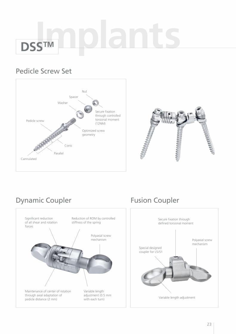
ImplantsPedicle Screw Set
Dynamic Coupler Fusion Coupler
Secure fixation through controlled torsional moment (12NM)
Optimizedscrewgeometry
Conic
Parallel
Pedicle screw
Cannulated
Washer
Spacer
Nut
Secure fixation through defined torsional moment
Polyaxial screw mechanism
Special designed coupler for L5/S1
Variable length adjustment
Polyaxial screwmechanism
Maintenance of center of rotation through axial adaptation of pedicle distance (2 mm)
Variable lengthadjustment (0.5 mmwith each turn)
Reduction of ROM by controlled stiffness of the spring
Significant reduction of all shear and rotation forces
DSSTM

DA
M00
003
11/0
2
PARADIGM SPINEP
Paradigm Spine GmbH
Eisenbahnstrasse 84
D-78573 Wurmlingen, Germany
Tel +49 (0) 7461 - 96 35 99 - 0
Fax +49 (0) 7461 - 96 35 99 - 20
www.paradigmspine.com