Embed Size (px)
Citation preview

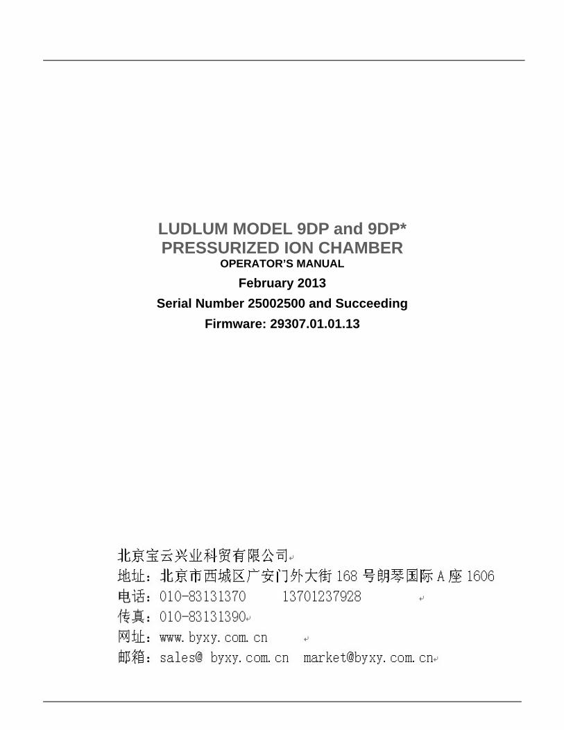
LUDLUM MODEL 9DP and 9DP* PRESSURIZED ION CHAMBER
OPERATOR’S MANUAL
LUDLUM MODEL 9DP and 9DP* PRESSURIZED ION CHAMBER
OPERATOR’S MANUAL
February 2013
Serial Number 25002500 and Succeeding
Firmware: 29307.01.01.13
MODEL 9DP and Model 9DP* Operator’s Manual
MODEL 9DP and Model 9DP* Operator’s Manual
Table of Contents
1. Introduction 1
2. Specifications 3
3. Control Panel 7
3.1 On/Off 8 3.2 Function 8 3.3 Audio 8 3.4 Ack/Reset 8
4. Display 10 4.1 Backlight 10 4.2 Startup 11 4.3 Instrument Information 11 4.4 Measurement View 11 4.4.1 Measurement Reading 12 4.4.2 Function Display 13 4.4.3 Status Icons 13 4.4.4 Messages 15 4.5 Changing the View 15
5. USB Port 16 5.1 Firmware Updating 16 5.1.1 Dimension File System 17 5.2 Data Logging 17 5.3 USB Keyboard Connection 17 5.4 Calibration 18
6. Keyboard Menu 19 6.1 Keyboard Controls 19 6.1.1 Sub Menus 19
MODEL 9DP and Model 9DP* Operator’s Manual
6.1.2 Non-Editable Fields 20 6.1.3 Editable Fields 20 6.2 Settings 21 6.2.1 Product 21 6.2.2 Language 21 6.2.3 Calendar 21 6.2.4 Clock 22 6.2.5 Passwords 22 6.2.6 System 23 6.3 Controls 24 6.3.1 Backlight 24 6.3.2 Audio 26 6.4 Features 27 6.4.1 Integrate 27 6.4.2 Data Logging 29 6.5 Display 33 6.5.1 Setup 33 6.5.2 View 1:R/hr 34 6.5.3 View 2:Sv/h 40 6.5.4 View 3:Gy/hr 40 6.5.5 View 4: 40 6.6 Functions 41 6.6.1 FCN 1:Integrate 41 6.6.2 FCN 2:Peak Rate 41 6.6.3 FCN 3: No Function 41 6.6.4 FCN 4: No Function 41
7. Data Logging 42
7.1 Data Description 42 7.1.1 Event 42 7.1.2 Type 42 7.1.3 Location 42 7.1.4 Status 42 7.1.5 Date 43 7.1.6 Time 43 7.1.7 Model 43 7.1.8 Serial Number 43 7.1.9 User ID Number 43 7.1.10 User Serial Number 43 7.1.11 Chamber Temperature 43
MODEL 9DP and Model 9DP* Operator’s Manual
7.1.12 High Voltage 43 7.1.13 Battery Voltage 44 7.1.14 Reading 44 7.1.15 Reading Multiplier 44 7.1.16 Reading Units 44 7.1.17 Integrate Reading 44 7.1.18 Integrate Multiplier 44 7.1.19 Integrate Units 45 7.2 Setup 45 7.2.1 Setup Logged Data 45 7.2.2 Setup Sample Period 45 7.2.3 Setup Delay on Power Up 45 7.2.4 Setup Operating Mode 45 7.2.5 Setup Power Up Mode 45 7.3 Operation 46 7.4 Data 46
8. Battery Power 47 8.1 Battery Installation 49 8.2 Battery Test 50 8.3 Removing Battery Pack 51 8.4 Optional Alkaline Battery Pack 51
9. Operational Test 52
10. Hazardous Shipping Classification 53
10.1 Depressurization 54 10.2 Transportation Special Permit 55
11. Options 61 11.1 Dimension Interface Kit 61 11.2 Audio Jack Output 61 11.3 Alkaline Battery Pack 62 11.4 Check Source 62
12. Safety Considerations and Maintenance 63 12.1 Environmental Conditions for Normal Use 63 12.2 Warning Markings and Symbols 63 12.3 Cleaning and Maintenance Precautions 65 12.4 Maintenance 66

MODEL 9DP and Model 9DP* Operator’s Manual
13. Certificate of Compliance 67
14. Recycling 68
MODEL 9DP and Model 9DP* Operator’s Manual
1
Introduction
The Ludlum Model 9DP is a modern, digital, hand-held pressurized ion chamber designed to detect gamma and X-ray energies above 25 keV. It will also see beta energies above 1 MeV. The instrument can be configured to read in either in units of Sv, R, or Gy and is readily changed by an administrator without requiring a new calibration. The instrument is auto-ranging with a rate measurement range of 0-50 mSv/h (0-5 R/hr, 0-50 mGy/h).
The Model 9DP* is a version of the Model 9DP Pressurized Ion Chamber that has a special chamber which has a flat energy response relative to ambient equivalent dose, or H*(10). The Model 9DP* firmware, software, and other electronics hardware is the same as the standard Model 9DP.
In addition to displaying the rate, the Model 9DP includes an operator-selectable function that additionally displays either the integrated reading or the peak reading. These two measurements are reset when the instrument is powered up and whenever manually reset by the operator.
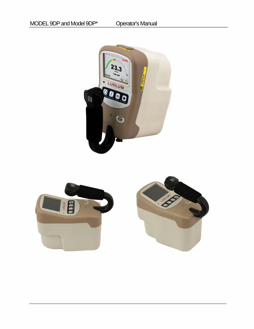
The Model 9DP features a 256K-color, 320 x 240 dpi LCD that displays each measurement along with the instrument status. The LCD is backlit and automatically adjusts to the surrounding ambient condition via a built-in light sensor within the instrument.
Four simple pushbuttons located below the LCD provide all the control functions for powering the instrument, enabling functions, adjusting the audio output, and either acknowledging alarms or resetting function values.
The ion chamber electronics automatically zeros the detector signal so operator adjustments are not necessary. The electronics additionally compensate for drift due to temperature changes over a range of -20 to 50 0C (-4 to 122 °F) to within 20%.
The Model 9DP includes a single USB port located at the front of the instrument that is protected by a cover. This port is used to communicate with the instrument during setup and calibration. Full parameter setup and calibration
Section
1
MODEL 9DP and Model 9DP* Operator’s Manual
2
requires Ludlum’s optional Dimension Interface Package (Part Number: 4293-763). A limited set of password-controlled administrator and user-level preferences can be adjusted by simply connecting the instrument directly to a standard USB keyboard.
The USB port may also be utilized to store captured measurement data onto a removable USB thumb drive for convenient retrieval by a PC spreadsheet or database program. Data capture frequency is administrator adjustable with all data stored in CSV file format.
The unit is powered by eight “AA” NIMH rechargeable batteries. Battery life largely depends upon the LCD backlighting and USB usage ranging from 12 to 30 hours.
The Model 9DP is equipped with a synthetically generated audible output that outputs clicks proportional to the radiation rate; however, no clicks will be heard when the meter deflection is less than 3%. This function can be turned on at multiple audible volume levels and shut-off.
Alarms can be enabled to alert the user whenever a pre-programmed level has been exceeded. The alarm can be acknowledged by the user to silence the audio even when the alarm condition remains. A second acknowledgement by the user will automatically re-arm the system.
The instrument case is constructed from resilient polycarbonate plastic, supported internally by a rigid metal frame. The internal electronics are designed with a solid state and are microprocessor based with low-power circuitry. The operating program is stored in non-volatile, rewritable flash memory.
MODEL 9DP and Model 9DP* Operator’s Manual
3
Specifications
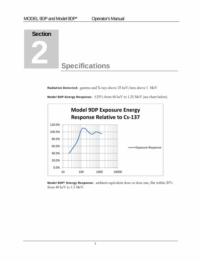
Radiation Detected: gamma and X-rays above 25 keV; beta above 1 MeV
Model 9DP Energy Response: ±25% from 60 keV to 1.25 MeV (see chart below)
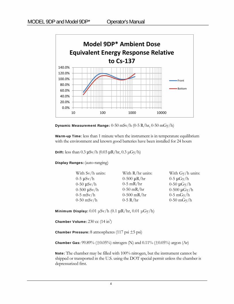
Model 9DP* Energy Response: ambient equivalent dose or dose rate, flat within 20% from 40 keV to 1.3 MeV.
0.0%
20.0%
40.0%
60.0%
80.0%
100.0%
120.0%
10 100 1000 10000
Model 9DP Exposure Energy Response Relative to Cs‐137
Exposure Response
Section
2
MODEL 9DP and Model 9DP* Operator’s Manual
4
Dynamic Measurement Range: 0-50 mSv/h (0-5 R/hr, 0-50 mGy/h)
Warm-up Time: less than 1 minute when the instrument is in temperature equilibrium with the environment and known good batteries have been installed for 24 hours
Drift: less than 0.3 µSv/h (0.03 µR/hr, 0.3 μGy/h)
Display Ranges: (auto-ranging)
With Sv/h units: With R/hr units: With Gy/h units: 0-5 µSv/h 0-500 µR/hr 0-5 µGy/h 0-50 µSv/h 0-5 mR/hr 0-50 µGy/h 0-500 µSv/h 0-50 mR/hr 0-500 µGy/h 0-5 mSv/h 0-500 mR/hr 0-5 mGy/h 0-50 mSv/h 0-5 R/hr 0-50 mGy/h
Minimum Display: 0.01 μSv/h (0.1 µR/hr, 0.01 μGy/h)
Chamber Volume: 230 cc (14 in3)
Chamber Pressure: 8 atmospheres (117 psi ±5 psi)
Chamber Gas: 99.89% (±0.05%) nitrogen (N) and 0.11% (±0.05%) argon (Ar)
Note: The chamber may be filled with 100% nitrogen, but the instrument cannot be shipped or transported in the U.S. using the DOT special permit unless the chamber is depressurized first.
0.0%
20.0%
40.0%
60.0%
80.0%
100.0%
120.0%
140.0%
10 100 1000 10000
Model 9DP* Ambient Dose Equivalent Energy Response Relative
to Cs‐137
Front
Bottom
MODEL 9DP and Model 9DP* Operator’s Manual
5
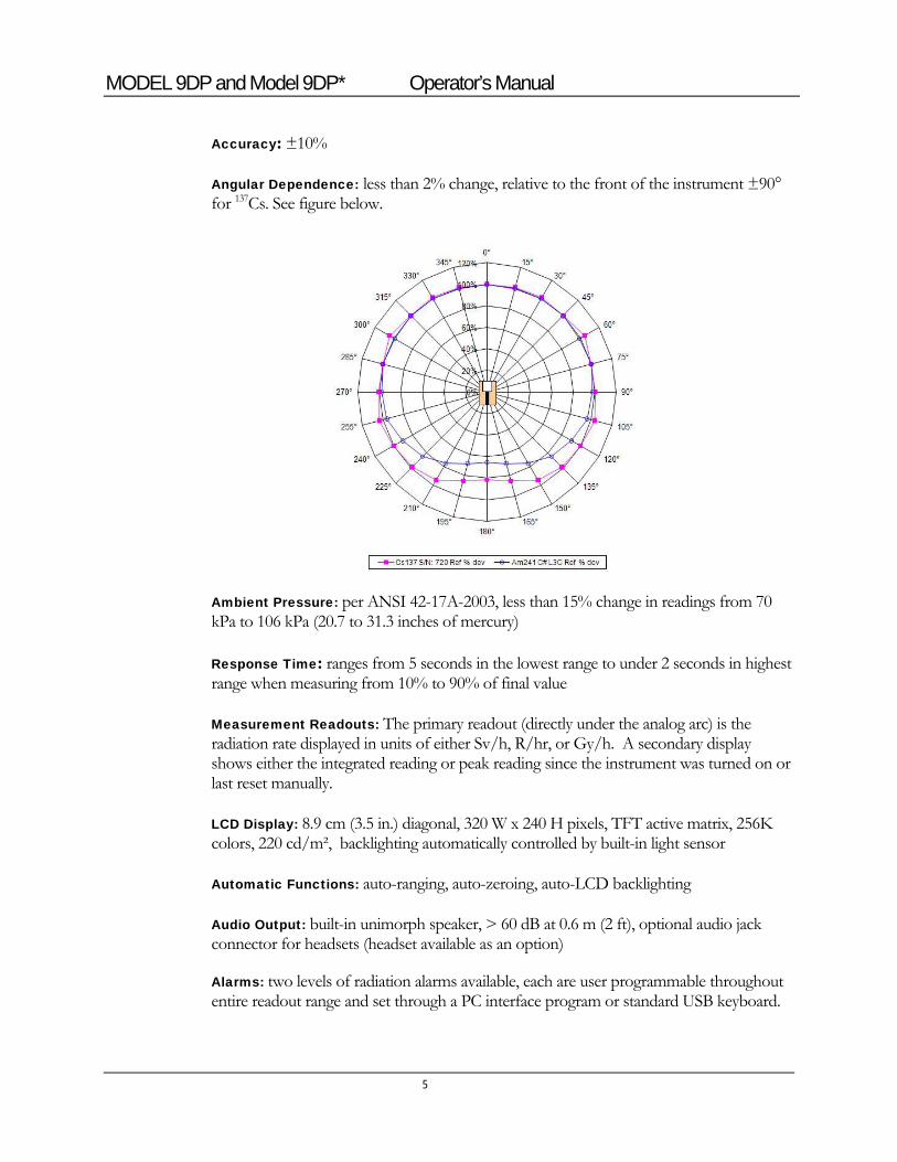
Accuracy: ±10%
Angular Dependence: less than 2% change, relative to the front of the instrument ±90° for 137Cs. See figure below.
Ambient Pressure: per ANSI 42-17A-2003, less than 15% change in readings from 70 kPa to 106 kPa (20.7 to 31.3 inches of mercury)
Response Time: ranges from 5 seconds in the lowest range to under 2 seconds in highest range when measuring from 10% to 90% of final value
Measurement Readouts: The primary readout (directly under the analog arc) is the radiation rate displayed in units of either Sv/h, R/hr, or Gy/h. A secondary display shows either the integrated reading or peak reading since the instrument was turned on or last reset manually.
LCD Display: 8.9 cm (3.5 in.) diagonal, 320 W x 240 H pixels, TFT active matrix, 256K colors, 220 cd/m², backlighting automatically controlled by built-in light sensor
Automatic Functions: auto-ranging, auto-zeroing, auto-LCD backlighting
Audio Output: built-in unimorph speaker, > 60 dB at 0.6 m (2 ft), optional audio jack connector for headsets (headset available as an option)
Alarms: two levels of radiation alarms available, each are user programmable throughout entire readout range and set through a PC interface program or standard USB keyboard.
MODEL 9DP and Model 9DP* Operator’s Manual
6
Data Logging: Data is stored to detachable USB thumb drive in CSV format for easy retrieval by PC spreadsheet/database programs. Data points include clock-generated date and time, rate, integrated reading, and instrument status. Logging time intervals are set by PC interface program or standard USB keyboard.
Temperature Range: the mean response from 0 to 40 °C (32 to 104 °F) shall be within
Temperature Range: the mean response from 0 to 40 °C (32 to 104 °F) shall be within 15% of the mean response determined at room temperature and the mean response from -20 to 0 °C (-4 to 32 °F) and 40 to 50 °C (104 to 122 °F) shall be within 20% of the mean response at room temperature.
Humidity Range: 0 to 95%, non-condensing
Geotropism: less than 1%
Power: eight rechargeable "AA" NiMH batteries; supplied with wall charger for direct connection to instrument
Battery Life: 12 to 30 hours between charges, depending upon use of backlighting
USB Interface: single USB port, meets USB 2.0 standard, may be connected directly to a USB keyboard to facilitate password-protected parameter changes, accepts USB thumb drive for storing logged data, optional interface kit facilitates connection to a PC for parameter editing and calibration
Construction: durable molded plastic with internal metal support
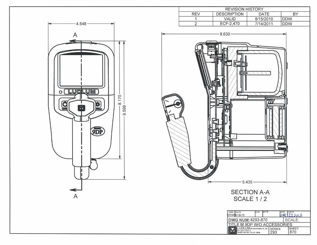
Size: 21.9 x 11.6 x 24.5 cm (8.6 x 4.6 x 9.6 in.) (H x W x L)
Weight: 1.5 kg (3.3 lb), including batteries
MODEL 9DP and Model 9DP* Operator’s Manual
Control Panel
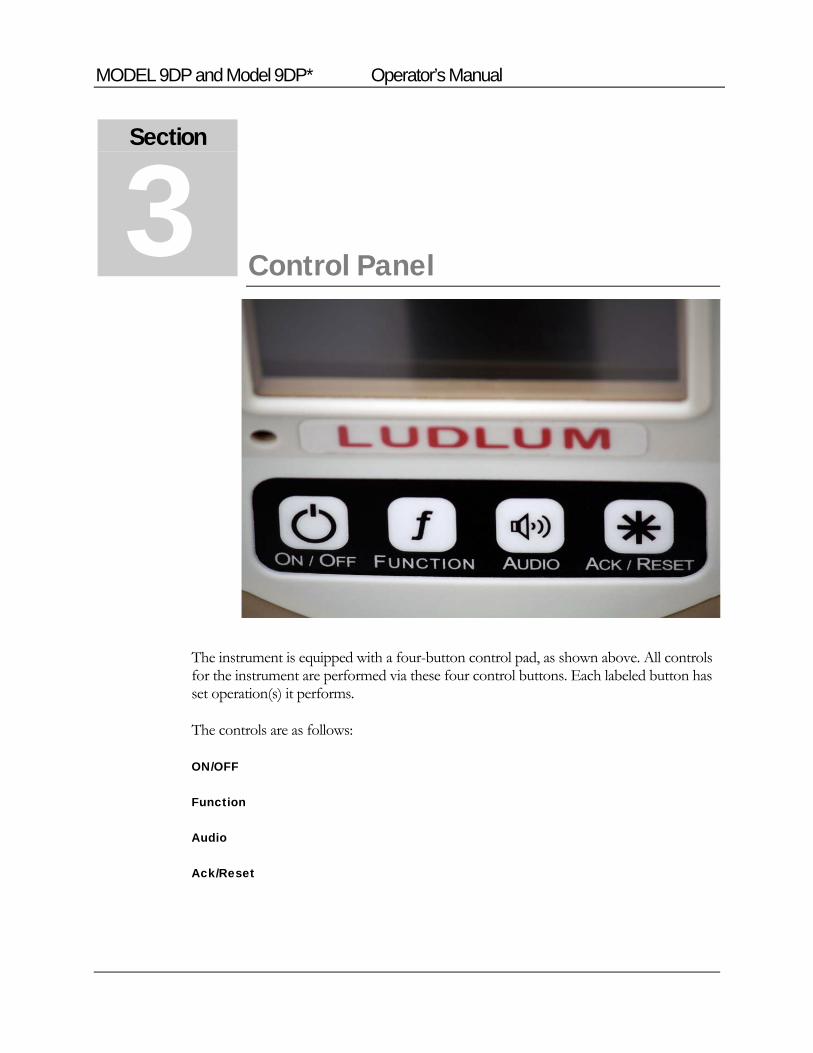
The instrument is equipped with a four-button control pad, as shown above. All controls for the instrument are performed via these four control buttons. Each labeled button has set operation(s) it performs.
The controls are as follows:
ON/OFF
Function
Audio
Ack/Reset
Section
3
MODEL 9DP and Model 9DP* Operator’s Manual
8
3.1 On/Off
This button is used to turn power on and off to the instrument. To turn on the instrument, only a momentary press is required. There is about a four to five-second delay before the screen wakes up and presents the Startup View.
To turn off the instrument, press the ON/OFF button by pressing and holding it down for approximately two seconds. When the system recognizes this command, it changes the screen to the System Status View with the message, “Instrument Shutting Down,” displayed.
3.2 Function
The Model 9DP supports built-in functions. These functions are displayed below the main instrument rate reading. Pressing the Function button switches the function to the next available function. Each function will have a unique identifier. See Functions in Section 6 for detail on the functions included.
3.3 Audio
The instrument includes an audible output proportional to the radiation rate and also to annunciate an alarm if activated within its programmed parameters. Pressing the audible button momentarily adjusts the volume output sequentially between OFF and five increasing audible levels before returning to the OFF position again. An icon on the bottom right-hand part of the screen indicates how many levels are currently activated and are shown as green bars.
3.4 Ack/Reset
This key is used to acknowledge alarms and to reset functions. Any time an alarm sounds, users can silence the audible output by pressing the ACK/RESET button. A second acknowledgement by the user will automatically clear the message and re-arm the system.
The ACK/RESET button may also be used to reset the current rate reading. If no alerts or alarms are present, a momentary press of the button will reset the current rate reading to “0.0”; however, the reading will immediately begin to update. As a result, the user may never see a “0.0” reading displayed.
This control can also be used in conjunction with resetting any functions utilizing this capability. The Model 9DP incorporates the Integrate and Peak functions, both of which allow resetting their values from the button.

MODEL 9DP and Model 9DP* Operator’s Manual
9
With the desired function presented on the display, the user can press the ACK/RESET button for three seconds, after which the function value will be reset to “0.0”. Note that the Peak function will display “0.0” only very briefly before it jumps to the value matching the current displayed value.
MODEL 9DP and Model 9DP* Operator’s Manual
10
Display
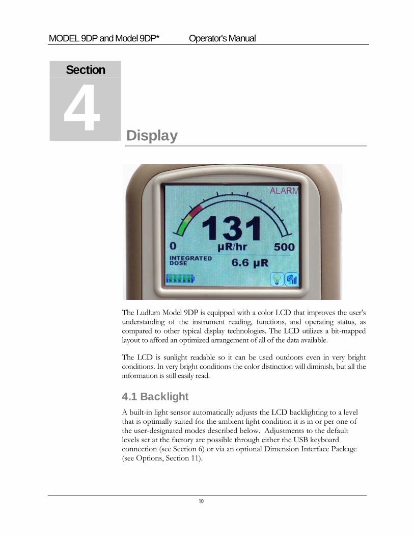
The Ludlum Model 9DP is equipped with a color LCD that improves the user’s understanding of the instrument reading, functions, and operating status, as compared to other typical display technologies. The LCD utilizes a bit-mapped layout to afford an optimized arrangement of all of the data available.
The LCD is sunlight readable so it can be used outdoors even in very bright conditions. In very bright conditions the color distinction will diminish, but all the information is still easily read.
4.1 Backlight A built-in light sensor automatically adjusts the LCD backlighting to a level that is optimally suited for the ambient light condition it is in or per one of the user-designated modes described below. Adjustments to the default levels set at the factory are possible through either the USB keyboard connection (see Section 6) or via an optional Dimension Interface Package (see Options, Section 11).
Section
4
MODEL 9DP and Model 9DP* Operator’s Manual
11
4.2 Startup Upon power-up, the instrument begins a self-diagnsotic routine, loads all of the stored data, and displays a company splash screen for approximately three seconds.
4.3 Instrument Information Immediately following startup, the instrument will next display pertinent instrument information. Information contained in this display includes:
Instrument Model Number (Model 9DP)
Instrument Serial Number: as assigned by Ludlum Measurements, Inc.
Firmware Version: identifying currently installed firmware.
User ID: This is an optional alpha-numeric field that can be programmed into the unit to identify the owner name/department/company etc.
User Serial Number: This is an optional alpha-numeric field that can be programmed into the unit to identify a unique serial number different from the instrument serial number assigned it by Ludlum. This may be useful for tracking company inventory using the owner’s numbering system.
Calibration Date: the date the instrument was last calibrated.
Calibration Due Date: the date the instrument should next be calibrated.
4.4 Measurement View The LCD displays the data captured by the ion chamber in a user customized format which, for the purpose of this manual, is referred to as a “view.”
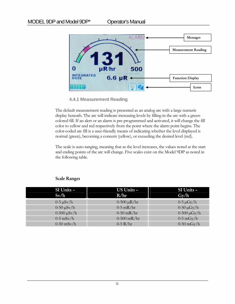
The view is broken down into three primary areas for displaying the measurement reading, the operative function, and the status icons. Messages are displayed in the area relevant to the message content.
MODEL 9DP and Model 9DP* Operator’s Manual
12
4.4.1 Measurement Reading
The default measurement reading is presented as an analog arc with a large numeric display beneath. The arc will indicate increasing levels by filling in the arc with a green-colored fill. If an alert or an alarm is pre-programmed and activated, it will change the fill color to yellow and red respectively from the point where the alarm point begins. The color-coded arc fill is a user-friendly means of indicating whether the level displayed is normal (green), becoming a concern (yellow), or exceeding the desired level (red).
The scale is auto-ranging, meaning that as the level increases, the values noted at the start and ending points of the arc will change. Five scales exist on the Model 9DP as noted in the following table.
Scale Ranges
SI Units – Sv/h
US Units – R/hr
SI Units – Gy/h
0-5 µSv/h 0-500 µR/hr 0-5 µGy/h 0-50 µSv/h 0-5 mR/hr 0-50 µGy/h 0-500 µSv/h 0-50 mR/hr 0-500 µGy/h 0-5 mSv/h 0-500 mR/hr 0-5 mGy/h 0-50 mSv/h 0-5 R/hr 0-50 mGy/h
Measurement Reading
Function Display
Icons
Messages
MODEL 9DP and Model 9DP* Operator’s Manual
13
4.4.2 Function Display
The Model 9DP comes pre-programmed with two functions which can be displayed. The function area is sandwiched between the measurement reading (above) and the instrument status (below).
Two functions that are pre-programmed are Integrate and Peak. Users can switch between these two functions by pressing the FUNCTION key on the control panel.
4.4.2.1 Integrate Function
The Integrate Function simply accumulates or integrates the rate reading while the instrument is turned on. The display reads, “Integrated Dose,” followed by the value and measurement unit as it accumulates. It is operative all the time, independent of whether or not this function is being displayed or not.
The default behavior of this function is that it automatically accumulates until it is reset. It is automatically reset every time the instrument is powered off. The integrated value can also be manually reset to “0” by pressing the ACK/RESET control button for three seconds while this function is being displayed.
Users who do not want the reading automatically reset when it is shut off can re-program the instrument to only reset when it is done via the manual method just described.
Integration will not occur for the first 60 seconds after the instrument is powered on to allow the instrument time to settle.
4.4.2.2 Peak Function
The Peak Function reads the highest measurement value attained since the instrument was last turned on. It remains active, independent of whichever function is currently being displayed. It is reset automatically when the instrument is shut off or can be manually reset by pressing the ACK/RESET control button for three seconds while this function is displayed. Peak readings will not be recorded during the first 30 seconds after the instrument is powered up to allow the instrument time to settle.
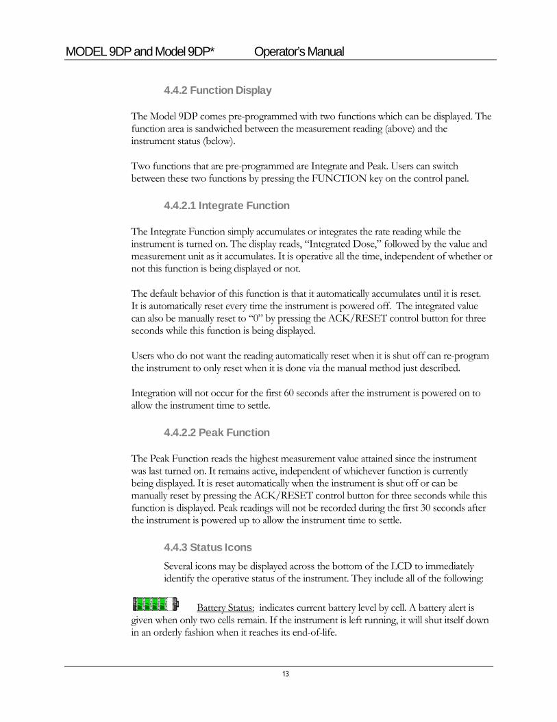
4.4.3 Status Icons Several icons may be displayed across the bottom of the LCD to immediately identify the operative status of the instrument. They include all of the following:
Battery Status: indicates current battery level by cell. A battery alert is given when only two cells remain. If the instrument is left running, it will shut itself down in an orderly fashion when it reaches its end-of-life.
MODEL 9DP and Model 9DP* Operator’s Manual
14
Battery Charging: is present any time the charger is plugged into the instrument and the battery is charging.
Backlight Off: Any time the LCD backlight is not on, this icon is presented.
LCD Auto Backlight On: is present whenever the instrument is programmed to automatically control the LCD backlight (default mode) and has become activated due to pre-programmed ambient conditions. The light level (20-100%) the unit is operating at is not displayed by this icon.
Manual or Temporary Mode Backlight On: Any time the instrument is set to operate, the backlight in either the Manual or the Temporary Mode will display the lit bulb icon.
Audible Output Level: The audible icon is always visible and indicates the status of the audible output that is associated with the measured radiation rate of the instrument. The green bars indicate increasing output levels by each added vertical bar. Pressing the Audio control button repeatedly on the instrument control panel will cycle the levels up through all five levels. After the fifth bar, the next indication is with no green bars notifying the user that the audible output is shut off.
Thumb Drive in Use: is indicated any time a thumb drive is plugged in, powered, and recognized by the instrument.
Keyboard Plugged In: Icon appears when keyboard is plugged in and recognized by the instrument. Press F1 to get Menu Mode. Press ESC to get out of Menu Mode.
Communication Cable: Icon appears when communication cable is initially plugged in.
MODEL 9DP and Model 9DP* Operator’s Manual
15
Communication Cable: Once the computer and instrument are successfully communicating, the “X” disappears (shown above), and this icon appears.
4.4.4 Messages Messages appear following either a pre-programmed alarm or to notify users of an operational or hardware-related failure.
4.4.4.1 Standard Alarm Messages The default ALERT and ALARM messages are activated whenever the values exceed their pre-programmed values. These alarm type messages are always posted in the upper right-hand side of the display.
4.4.4.2 Custom Messages If desired, custom messages (approximately 50 characters in length) can be programmed to display in lieu of either the default alert or alarm messages. Under this method, any time either alarm type is activated, a new window appears over-writing the Measurement View with the alarm type (ALERT or ALARM) posted boldly across the new window and the custom message below it. This window additionally includes soft-key buttons along the bottom, identifying which control button(s) to push for continued operation and action.
4.4.4.3 Failure Messages A number of instrument failure messages are designed into the instrument to alert the user of certain situations. These messages will be posted in the Instrument Status area where the icons are normally present and will override the icons until the problem is corrected.
Messages in this category include:
USB Error Messages
4.5 Changing the View The Model 9DP is programmed to only have one view. This view may, however, be exchanged for one of three other views already pre-programmed into the instrument. Exchanging views can be accomplished by connecting a standard USB keyboard to the instrument and selecting the desired view. See Section 5.4 for more detail.
MODEL 9DP and Model 9DP* Operator’s Manual
USB Port
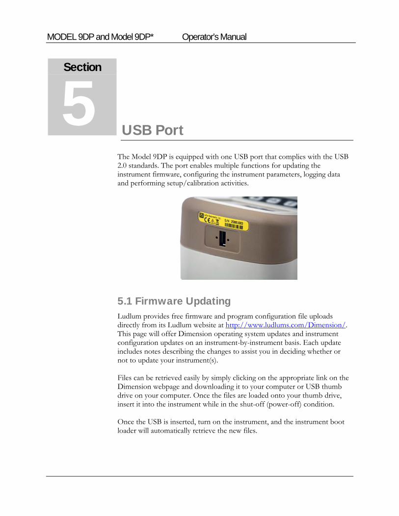
The Model 9DP is equipped with one USB port that complies with the USB 2.0 standards. The port enables multiple functions for updating the instrument firmware, configuring the instrument parameters, logging data and performing setup/calibration activities.
5.1 Firmware Updating Ludlum provides free firmware and program configuration file uploads directly from its Ludlum website at http://www.ludlums.com/Dimension/. This page will offer Dimension operating system updates and instrument configuration updates on an instrument-by-instrument basis. Each update includes notes describing the changes to assist you in deciding whether or not to update your instrument(s). Files can be retrieved easily by simply clicking on the appropriate link on the Dimension webpage and downloading it to your computer or USB thumb drive on your computer. Once the files are loaded onto your thumb drive, insert it into the instrument while in the shut-off (power-off) condition. Once the USB is inserted, turn on the instrument, and the instrument boot loader will automatically retrieve the new files.
Section
5
MODEL 9DP and Model 9DP* Operator’s Manual
17
5.1.1 Dimension File System Dimension files that define the instrument operation and functionality consist of two types: the operating system and the instrument configuration file. It is important to note that uploading any new files does not negate your current calibration. The operating system file is universal to all Dimension products of the same model type and is always named as firmware.hex. This file is similar in nature to Windows® or Linux® for PCs in that it provides the background, environment enabling real-time operation of the instrument hardware and resources. Uploading operating system file updates does not fundamentally impact your current instrument/system except in cases where: a) a software bug was fixed that applies to your instrument b) a new feature is added and deliberately implemented. Instrument configuration files only apply to a single Ludlum instrument model within the Dimension family. These files determine the features and functions that are available for a given instrument model. The Dimension webpage will have specific configuration files for each instrument model as they become available. These file names can be customized to fit the particular model number or perhaps a specific name reflecting an instrument configuration of the instrument owner’s choosing. The file format will always have a .cfg extension. For example, the Model 9DP file name might be “M9DP.cfg.” When the instrument attempts to load a new configuration file from the thumb drive, it will load the first file so be sure that only the new configuration file exists on the thumb drive.
5.2 Data Logging This use of the USB port enables capturing logged data and having it stored onto a USB thumb drive inserted into the instrument’s USB port. The file is a CSV (comma separated value) type and is named output.log. The CSV file type is universal and can easily be read into your favorite PC spreadsheet or database program for performing, reporting, and data analysis functions.
5.3 USB Keyboard Connection Users can connect a standard USB keyboard directly into the instrument USB port to edit parameters under password control. When the instrument is turned on, it will sense the keyboard.
MODEL 9DP and Model 9DP* Operator’s Manual
18
5.4 Calibration Complete setup and calibration capability can be accessed by connecting the instrument to a PC via Ludlum’s optional Dimension Interface Kit. This kit includes Windows® PC software, plus a special USB cable with a built-in adaptor. The Dimension Interface Kit part number is 4293-763.
MODEL 9DP and Model 9DP* Operator’s Manual
19
Keyboard Menu
A standard USB keyboard may be connected to the instrument via the USB port. Once connected, the keyboard icon will appear on the icon display line letting the user know that the keyboard is attached and ready.
6.1 Keyboard Controls Pressing “F1” on the keyboard will take the user to a menu screen that will allow the user the ability to make changes to the instrument configuration without the need to connect the instrument to a computer.
The menu offerings are as follows:
Settings
Controls
Features
Display
Functions
Exit
To navigate through the menu, use the up and down arrows on the keyboard. As the arrows are pressed, the green bar will move up or down to highlight the appropriate keyboard menu line. Once the appropriate menu line is selected, press Enter to advance to the next screen.
6.1.1 Sub Menus If the selected menu line is a sub-menu heading, a new menu will appear. The user can then navigate through the new menu to select another menu line or select “<-Back” to return to the previous menu.
Section
6
MODEL 9DP and Model 9DP* Operator’s Manual
20
6.1.2 Non-editable Fields If the selected menu line is a non-editable field, the current value for the menu item will be displayed as well as the “<-Back” menu line. Only the “<-Back” menu line may be used, which will return the user to the previous screen.
6.1.3 Editable Fields If the selected menu line is an editable field, the current value for the menu item will be displayed as well as the “<-Back” menu line. Highlighting the menu item and pressing enter will change the menu line color from green to black, indicating that the value may be changed.
6.1.3.1 Numerical Fields If the menu item is a numerical value, the up and down arrows may be used to change the value of the menu item. Each press of the up/down arrow keys will increment/decrement the numerical value by a value of 1. Pressing and holding the up/down arrow keys will increment/decrement the numerical value by a value of 1 for the first 10 counts. After 10 counts, the numerical value will start to increment/decrement by a value of 5 for the next 10 counts, after which the value will increase by a value of 50. Releasing the key at any time will restart the count increment at 1. When the appropriate value is reached, press Enter to keep the value, and the menu line should change from black to green.
6.1.3.2 Text Fields If the menu item is a text value, use the keyboard to type the appropriate text into the field. Text fields only accept alpha-numeric characters and spaces. No other character should be used. When the appropriate value is entered, press enter to keep the value, and the menu line should change from black to green.
The backspace may be used to delete unwanted characters in the event a mistake was made. No other special control keys are available to help edit the text.
6.1.3.3 Special Fields If the menu item is a special field, the up and down arrows may be used to scroll through the available values for the particular field. When the appropriate value is reached, press enter to keep the value, and the menu line should change from black to green.
Note: If the arrow is pressed and held, the same rules apply as though it were a numeric field. Holding the arrow for more than 10 counts, may result in some unusual behavior but will not cause harm to the instrument.
MODEL 9DP and Model 9DP* Operator’s Manual
21
6.2 Settings “Settings” menu allows the user to not only see information about the instrument that was programmed at the factory, but also to set some basic system information.
6.2.1 Product “Product” is a sub-menu which grants access to the “Model,” “Ludlum Serial Number,” “User ID Number,” and “User Serial Number.”
6.2.1.1 Model “Model” represents Ludlum’s model number assigned by Ludlum Measurements at the factory and is a view only field.
6.2.1.2 Ludlum Serial Number “Ludlum Serial Number” represents the serial number assigned by Ludlum Measurements at the factory and should match the serial number located on the yellow label located just above the USB port. This is a view only field.
6.2.1.3 User ID Number “User ID Number” can be assigned by the user and is treated as a text string even if the value is completely numeric. The field is limited to 16 characters.
6.2.1.4 User Serial Number “User Serial Number” can be assigned by the user and is treated as a text string even if the value is completely numeric. The field is limited to 16 characters.
6.2.2 Language “Language” can be used to select the language used by the 9DP; however, the only language currently supported by the 9DP is English. As a result, this field is a view only field.
6.2.3 Calendar “Calendar” is a sub-menu which grants access to the Month, Day, and Year associated with the calendar.
6.2.3.1 Month “Month” represents the current calendar month and is a special field.
MODEL 9DP and Model 9DP* Operator’s Manual
22
6.2.3.2 Day “Day” represents the current calendar day and is a numeric field. Valid values for “Day” are 1 to 31.
Note: When selecting the day, any value from 1 to 31 may be entered, as the instrument does not verify the day versus the number of days available in the current month; however, the clock will adjust to a valid date at midnight when the calendar day changes.
6.2.3.3 Year “Year” represents the current calendar year and is a numeric field. Valid values for “Year” are 2000 to 2099.
6.2.4 Clock “Clock” is a sub-menu which grants access to the “Hours,” “Minutes,” “Seconds,” and “Format” associated with the clock.
6.2.4.1 Hours “Hours” represents the current clock hour in 24-hour notation and is a numeric field. Valid values for “Hours” are 00 to 23.
6.2.4.2 Minutes “Minutes” represents the current clock minutes and is a numeric field. Valid values for “Minutes” are 00 to 59.
6.2.4.3 Seconds “Seconds” represents the current clock seconds and is a numeric field. Valid values for “Seconds “are 00 to 59.
6.2.4.4 Format “Format” represents the format in which clock information is displayed. “Format” is a special field with valid values of 12 and 24.
6.2.5 Passwords “Passwords” is a sub-menu which grants access to the “Password Enable,” “Password 1,” “Password 2,” and “Password 3” fields associated with the password menu. If passwords are enabled, the instrument will require that a password be entered into the instrument to allow access to the keyboard menu. The instrument will compare the entered password against each stored password, and if a valid match is found, the user will be granted the appropriate level of
MODEL 9DP and Model 9DP* Operator’s Manual
23
access to the keyboard menu. Press enter when the approved level of access is displayed to access the keyboard menu or “<- Exit” to exit the keyboard menu. If the password was not approved, pressing Enter will force the user out of the keyboard menu, and the user will have to press F1 to try again.
If even one password is left blank, pressing enter with a blank password when a password is required will grant that user access to the menu at the highest appropriate password level.
Note: Currently, only one level of passwords exists.
6.2.5.1 Enable “Enable” represents the current state of the password system and is a special field. If the value is “Off,” no password is required to gain access to the keyboard menu. If the value is “On,” a valid password is required to gain access to the keyboard menu.
6.2.5.2 Password 1 “Password 1” represents the user level of keyboard menu access and is a text field. The field is limited to 16 characters and is case sensitive.
6.2.5.3 Password 2 “Password 2” represents the manager level of keyboard menu access and is a text field. The field is limited to 16 characters and is case sensitive.
6.2.5.4 Password 3 “Password 3” represents the administrator level of keyboard menu access and is a text field. The field is limited to 16 characters and is case sensitive.
6.2.6 System “System” is a sub-menu which grants access to the “Firmware Number.”
6.2.6.1 Firmware Number “Firmware Number” is the current version of main firmware that the 9DP is currently using and is a view-only field. This information is necessary when downloading the appropriate files from the Ludlum website should a firmware revision be required in the future.
MODEL 9DP and Model 9DP* Operator’s Manual
24
6.3 Controls “Controls” menu allows the user to set some basic system information regarding the interface hardware used by the instrument. The two primary controls available include the LCD “Backlight” and the “Audio” output.
6.3.1 Backlight “Backlight” is a sub-menu which grants access to the “Power Up Mode,” “Operating Mode,” and light mode settings associated with the backlight.
There are three different operating modes for LCD backlighting: auto, manual, and temporary. There is no direct user control for changing the backlight or manipulating the power setting outside of the USB keyboard menu.
The default operating mode is Auto. Users can modify the operating mode and associated selectable parameters within each mode.
6.3.1.1 Power Up Mode “Power Up Mode” represents the state in which the backlight will operate when power is applied to the instrument and is a special field.
The definitions of the backlight power-up modes are:
“Default” o “Default” was pre-defined by Ludlum Measurements and is the
“Auto” mode. “Last”
o Last indicates that the instrument will power up in the same backlight “Operating Mode” the instrument was using at the time the instrument was last powered down.
“Auto” o A light sensor above the control panel of the instrument will
detect changes in the ambient lighting conditions and automatically adjust the backlight level to 20%, 60%, or 100% of the backlight power. The lighting values can be re-programmed to other values (see 6.3.1.5 Auto Mode Settings).
“Off” o This mode sets the backlight to the level defined as the “Off”
level. The backlight level for the “Off” setting is always 0%. “On”
o This mode sets the backlight to the level defined by the “Always On Level.” The default backlight level for “Always On Level” is 100%.
MODEL 9DP and Model 9DP* Operator’s Manual
25
“Temporary” o This mode automatically activates the backlight to a preset level
defined by the “Always On Level” for a user-adjustable set period of time defined in “Temporary Display Time” any time a key is pressed on the keypad. The default values are 100% backlit with 10-second duration. The backlight is also activated when an alert or alarm becomes active under this mode.
6.3.1.2 Operating Mode “Operating Mode” represents the current operating mode for the backlight. “Operating Mode” is a special field with valid values of “Off,” “On,” “Auto,” and “Temporary” as described in section 6.3.1.1.
6.3.1.3 Temporary Display Time “Temporary Display Time” represents the length that the backlight will remain on in seconds when the instrument backlight is operating in “Temporary” mode. The display time is a numeric field.
6.3.1.4 Always On Level “Always On Level” represents the backlight level that the backlight will operate at when the instrument backlight is operating in the “On” mode or the “Temporary” mode, assuming that a key has been pressed. “Always On Level” is a numeric field displayed in percentage.
6.3.1.5 Auto Mode Settings “Audio Mode Settings” is a sub-menu allowing access to the low, medium, and high backlight level settings.
When the backlight is operating in “Auto” mode, the backlight can adjust to three separate levels, depending on the amount of light detected by the instruments light sensor.
6.3.1.5.1 Low Level Backlight “Low Level Backlight” represents the percentage level for the backlight when the instrument detects the maximum amount of ambient light. The low-level backlight is a numeric field displayed in percentage with a default value of 20%.
6.3.1.5.2 Medium Level Backlight “Medium Level Backlight” represents the percentage level for the backlight when the instrument detects an average amount of ambient light. The medium level backlight is a numeric field displayed in percentage with a default value of 60%.
MODEL 9DP and Model 9DP* Operator’s Manual
26
6.3.1.5.3 High Level Backlight “High Level Backlight” represents the percentage level for the backlight when the instrument detects the least amount of ambient light. The high-level backlight is a numeric field displayed in percentage with a default value of 100%.
6.3.2 Audio “Audio” is a sub-menu which grants access to the “Power Up Mode,” “Operating Mode,” and level settings associated with the built-in unimorph; above and beyond the audio keypad switch, which offers direct user control for changing the audio level when the USB keyboard is not connected.
6.3.2.1 Power Up Mode “Power Up Mode” represents the state in which the audio will operate when power is applied to the instrument and is a special field.
The definitions of the backlight power-up modes are:
“Default” o “Default” was pre-defined by Ludlum Measurements and is the
40%. “Last”
o Last indicates that the instrument will power up in the same audio “Operating Mode” the instrument was using at the time the instrument was last powered down.
“Off” o This mode sets the audio level to 0% on power up.
“On” o This mode currently sets the audio level to 40%, similar to the
“Default” setting.
6.3.2.2 Operating Mode “Operating Mode” represents the current operating mode for the audio. “Operating Mode” is a special field with valid values of 0%, 20%, 40%, 60%, 80%, and 100%.
6.3.2.3 Alert Level “Alert Level” represents the audio level associated with an alert message. “Alert Level” is a numeric field with valid values from 0 to 100 displayed in percentages.
MODEL 9DP and Model 9DP* Operator’s Manual
27
6.3.2.4 Alarm Level “Alarm Level” represents the audio level associated with an alarm message. “Alarm Level” is a numeric field with valid values from 0 to 100 displayed in percentages.
6.4 Features “Features” menu allows the user to set up special capabilities of the 9DP. The two primary features available include the “Integrate” and the “Data Logging” features.
6.4.1 Integrate “Integrate” is a sub-menu which grants access to the “Power Up Mode,” “Operating Mode,” and settings associated with the integrate feature.
The instrument is designed to calculate an integrated dose when the Integrate feature is enabled. This feature also controls how the integrated dose reading will be reported to a file or streamed to a computer (with the appropriate interface cable and software) if the integrated dose is being recorded.
6.4.1.1 Power Up Mode “Power Up Mode” represents the state in which the integrated feature will operate when power is applied to the instrument and is a special field.
The definitions of the integrated dose power-up modes are:
“Default” o “Default” was pre-defined by Ludlum Measurements and is
“On.” “Last”
o “Last” indicates that the instrument will power up in the same “Operating Mode” the instrument was using at the time the instrument was last powered down.
“Off” o This mode turns the integrate feature “Off.”
“On” o This mode turns the integrate feature “On.”
6.4.1.2 Operating Mode “Operating Mode” represents the current operating mode for the integrate feature. “Operating Mode” is a special field with valid values of “Off” or “On.”
MODEL 9DP and Model 9DP* Operator’s Manual
28
6.4.1.3 Delay On Power Up “Delay On Power Up” represents the amount of time in seconds that the instrument must wait on power-up before readings are added to the integrated dose accumulation. “Delay On Power Up” is a numeric field with valid values from 1 to 180.
6.4.1.4 Save On Shutdown “Save On Shutdown” represents the ability to save the current integrated dose on shut-down and use the value as the initial value the next time the instrument is powered on. “Save On Shutdown” is a special field with valid values of “On” or “Off.”
6.4.1.5 Logging Report “Logging Report” is a sub-menu which grants access to “Log On Start Up” and “Log Before Shut Down” associated with logging the integrated dose.
6.4.1.5.1 Log On Start Up “Log On Start Up” represents the ability to log the integrated dose to the thumb drive after the power-up delay. “Log On Start Up” is a special field with valid values of “Off” and “On.”
6.4.1.5.2 Log Before Shut Down “Log Before Shut Down” represents the ability to log the integrated dose to the thumb drive before the instrument completes its shut-down procedure. “Log Before Shut Down” is a special field with valid values of “Off” and “On.”
6.4.1.6 Value Menu “Value Menu” is a sub-menu which grants access to the “Value,” “Multiplier,” and “Units” associated with the integrated dose reading.
The “Integrate” feature collects the integrated dose and stores it based on the settings of “Multiplier” and “Units.” The user can change the multiplier and units, which will immediately adjust the value to the appropriate reading. The settings for “Multiplier” and “Units” also determines how the integrated dose information will be reported if data logging is enabled.
The integrated dose is also viewable on the measurement view if the “Integrated Dose” function is loaded. The multiplier set in the “Integrate” feature is also the multiplier used as the base multiplier by the “Integrated Dose” function; however, as the integrate value increases, the “Integrated Dose” function will auto range the multiplier while the “Integrate” feature multiplier remains the
MODEL 9DP and Model 9DP* Operator’s Manual
29
same. The units assigned in the “Integrate” feature have no effect on the “Integrated Dose” function unless the view element does not have an appropriate unit assigned. Only then will the “Integrated Dose” function rely upon the “Integrate” feature units for proper calculation.
Note: The “Integrated Dose” function grants the user the ability to reset the integrated dose collected by the instrument; however, the “Integrate” feature controls whether the integrated dose is functioning or not. If the “Integrate” feature is “Off,” no data updates will be displayed by the “Integrated Dose” function.
6.4.1.6.1 Value “Value” represents the current numerical value of the integrated dose given the supplied multiplier and units. “Value” is a non-editable field.
6.4.1.6.2 Multiplier “Multiplier” represents the current multiplier associated with the integrated dose. “Multiplier” is a special field with valid values of micro, milli, unity, kilo, and mega.
6.4.1.6.3 Units “Units” represents the current units associated with the integrated dose. “Units” is a special field with valid values of “R,” “Sv,” “Gy,” and “REM.”
6.4.2 Data Logging “Data Logging” is a sub-menu which grants access to the “Power Up Mode,” “Operating Mode”, and settings associated with the data logging feature.
6.4.2.1 Power Up Mode “Power Up Mode” represents the state in which the data logging feature will operate when power is applied to the instrument and is a special field.
The definitions of the data logging power-up modes are:
“Default” o “Default” was pre-defined by Ludlum Measurements and is
“Off.” “Last”
o “Last” indicates that the instrument will power up in the same “Operating Mode” the instrument was using at the time the instrument was last powered down.
“Off”
MODEL 9DP and Model 9DP* Operator’s Manual
30
o This mode turns the data logging feature “Off.” “On”
o This mode turns the data logging feature “On.”
6.4.2.2 Operating Mode “Operating Mode” represents the current operating mode for the data logging feature. “Operating Mode” is a special field with valid values of “Off” or “On.”
6.4.2.3 Delay On Power Up “Delay On Power” represents the amount of time in seconds that the instrument must wait on power-up before data logging starts logging data. “Delay On Power Up” is a numeric field with valid values from 1 to 180.
6.4.2.4 Sample Period “Sample Period” represents the amount of time in seconds that the instrument must wait between reporting data logging events. “Sample Period” is a numeric field with valid values from 1 to 3600 (1 hour).
6.4.2.5 Report Setup “Report Setup” is a sub-menu which grants access to the “System,” “Instrument,” and “Readings” values that are to be reported by the data logging feature.
6.4.2.5.1 System “System” is a sub-menu which grants access to the “Date,” “Time,” and instrument settings to be reported by the data logging feature.
6.4.2.5.1.1 Date Enabling “Date” will cause the data logging feature to report the current date during each logging event. Otherwise, the date field should be disabled. “Date” is a special field with valid values of “Off” and “On.”
6.4.2.5.1.2 Time Enabling “Time” will cause the data logging feature to report the current time during each logging event. Otherwise, the time field should be disabled. “Time” is a special field with valid values of “Off” and “On.”
6.4.2.5.1.3 Chamber Temperature Enabling “Chamber Temperature” will cause the data logging feature to report the temperature currently being recorded by the ion chamber during each logging
MODEL 9DP and Model 9DP* Operator’s Manual
31
event. Otherwise, the chamber temperature field should be disabled. “Chamber Temperature” is a special field with valid values of “Off” and “On.”
6.4.2.5.1.4 High Voltage Enabling “High Voltage” will cause the data logging feature to report the wall voltage associated with the ion chamber during each logging event. Otherwise, the high-voltage field should be disabled. “High Voltage” is a special field with valid values of “Off” and “On.”
6.4.2.5.1.5 Battery Voltage Enabling “Battery Voltage” will cause the data logging feature to report the instruments battery voltage during each logging event. Otherwise, the battery voltage field should be disabled. “Battery Voltage” is a special field with valid values of “Off” and “On.”
6.4.2.5.2 Instrument “Instrument” is a sub-menu which grants access to the “Model,” “Ludlum Serial Number,” “User ID Number,” and “User Serial Number” settings to be reported by the data logging feature.
6.4.2.5.2.1 Model Enabling “Model” will cause the data logging feature to report the Ludlum Measurements model during each logging event. Otherwise, the “Model” field should be disabled. Model is a special field with valid values of “Off” and “On.”
6.4.2.5.2.2 Serial Number Enabling “Serial Number” will cause the data logging feature to report the Ludlum Measurements serial number during each logging event. Otherwise, the serial number field should be disabled. “Serial Number” is a special field with valid values of “Off” and “On.”
6.4.2.5.2.3 User ID Number Enabling “User ID Number” will cause the data logging feature to report the user ID number assigned by the user during each logging event. Otherwise, the user ID number field should be disabled. “User ID Number” is a special field with valid values of “Off” and “On.”
6.4.2.5.2.4 User Serial Number Enabling “User Serial Number” will cause the data logging feature to report the user serial number assigned by the user during each logging event. Otherwise, the
MODEL 9DP and Model 9DP* Operator’s Manual
32
user serial number field should be disabled. “User Serial Number” is a special field with valid values of “Off” and “On.”
6.4.2.5.3 Readings “Readings” is a sub-menu which grants access to the instrument readings to be reported by the data logging feature. This includes both the rate and integrated dose readings.
6.4.2.5.3.1 Reading Enabling “Reading” will cause the data logging feature to report the current rate reading during normal logging events. The value of “Reading” can also report other values depending on the event type. For instance, if reporting the integrated dose (Event Type = 2) on power-down is enabled, “Reading” will represent the integrated dose value if enabled. If the reading is not to be reported, the field should be disabled. “Reading” is a special field with valid values of “Off” and “On.”
6.4.2.5.3.2 Reading Multiplier Enabling “Reading Multiplier” will cause the data logging feature to report the current rate reading multiplier during normal logging events. The value of “Reading Multiplier” can also report other values depending on the event type. For instance, if reporting the integrated dose (Event Type = 2) on power-down is enabled, “Reading Multiplier” will represent the integrated dose multiplier if enabled. If the reading multiplier is not to be reported, the field should be disabled. “Reading Multiplier” is a special field with valid values of “Off” and “On.”
6.4.2.5.3.3 Reading Units Enabling “Reading Units” will cause the data logging feature to report the current rate reading units during normal logging events. The value of “Reading Units” can also report other values depending on the event type. For instance, if reporting the integrated dose (Event Type = 2) on power-down is enabled, “Reading Units” will represent the integrated dose units if enabled. If the reading units are not to be reported, the field should be disabled. “Reading Units” is a special field with valid values of “Off” and “On.”
6.4.2.5.3.4 Integrated Reading Enabling “Integrated Reading” will cause the data logging feature to report the current integrated dose reading during normal logging events. Otherwise, the field should be disabled. “Integrated Reading” is a special field with valid values of “Off” and “On.”
MODEL 9DP and Model 9DP* Operator’s Manual
33
6.4.2.5.3.5 Integrated Multiplier Enabling “Integrated Multiplier” will cause the data logging feature to report the current integrated dose multiplier during normal logging events. Otherwise, the field should be disabled. “Integrated Multiplier” is a special field with valid values of “Off” and “On.”
6.4.2.5.3.6 Integrated Units Enabling “Integrated Units” will cause the data logging feature to report the current integrated dose units during normal logging events. Otherwise, the field should be disabled. “Integrated Units” is a special field with valid values of “Off” and “On.”
6.5 Display “Display” menu allows the user to set up the views associated with the 9DP. The 9DP comes pre-configured with three views, identical in every detail with the exception of the units.
6.5.1 Setup “Setup” is a sub-menu allowing access to the “Power Up Mode” and “Current View” associated with the measurement view of the 9DP.
6.5.1.1 Power Up Mode “Power Up Mode” represents the state in which the measurement view will operate when power is applied to the instrument. “Power Up Mode” is a special field.
The definitions of the display power-up modes are:
“Default” o “Default” was pre-defined by Ludlum Measurements and is
“View 1.” “Last”
o “Last” indicates that the instrument will power up in the same “Operating Mode” the instrument was using at the time the instrument was last powered down.
“View 1” o The instrument will power up in “View 1: R/hr”.
“View 2” o The instrument will power up in “View 2: Sv/h”.
“View 3” o The instrument will power up in “View 3: Gy/h”.
MODEL 9DP and Model 9DP* Operator’s Manual
34
“View 4” o The instrument will power up in “View 4:”.
6.5.1.2 Current View “Current View” represents the current operating mode for the measurement view. “Current View” is a special field with valid values of “View 1,” “View 2,” “View 3,” and “View 4.”
6.5.2 View 1: R/hr “View 1: R/hr” is a sub-menu allowing access to the “Appearance,” “Functions,” “Alerts,” and “Alarms” associated with the “View 1: R/hr”.
6.5.2.1 Appearance “Appearance” is a sub-menu allowing access to the “Background Color” and “Foreground Color” associated with “View 1: R/hr.”
6.5.2.1.1 Background Color “Background Color” represents the color of the background of View 1. “Background Color” is a special field with valid values of “White,” “Yellow,” “Light Magenta,” “Light Red,” “Light Cyan,” “Light Green,” “Light Blue,” “Dark Gray,” “Light Gray,” “Brown,” “Magenta,” “Red,” “Cyan,” “Green,” “Blue,” “Bright Yellow,” “Bright Magenta,” “Bright Red,” “Bright Cyan,” “Bright Green,” “Bright Blue,” “Black,” and seven shades of gray.
6.5.2.1.2 Foreground Color “Foreground Color” represents the color of the foreground of View 1. “Foreground Color” is a special field with valid values of “White,” “Yellow,” “Light Magenta,” “Light Red,” “Light Cyan,” “Light Green,” “Light Blue,” “Dark Gray,” “Light Gray,” “Brown,” “Magenta,” “Red,” “Cyan,” “Green,” “Blue,” “Bright Yellow,” “Bright Magenta,” “Bright Red,” “Bright Cyan,” “Bright Green,” “Bright Blue,” “Black,” and seven shades of gray.
6.5.2.2 Functions “Functions” is a sub-menu allowing the user to set up the four functions that may be accessed via the function key on the instrument keypad while in View 1.
Each instrument can store up to four functions. These functions are stored at the instrument level (see Section 6.6). At the view level, the user may select as many as four functions to have access to, via the Function key on the instrument keypad. The instrument comes pre-configured with access to the two default instrument functions.
MODEL 9DP and Model 9DP* Operator’s Manual
35
6.5.2.2.1 FCN 1: <function name> “FCN 1” is a sub-menu that allows access to Function 1 of the current view, including the function selected and the function enabled.
6.5.2.2.1.1 FCN 1: <function name> “FCN 1” represents the instrument function selected for the current view. “FCN 1” is a special field and valid values include “Integrate,” “Peak Rate,” and any additional functions that may have been added since the instrument left the factory.
“No Function” is an indication that an existing instrument function location is selected; however, no function has been loaded into the instrument function location.
“- empty -“ is an indication that no instrument function location has been selected and the function is therefore empty.
6.5.2.2.1.2 FCN 1: Enable “FCN 1: Enable” represents the ability to enable the current function for the current view. If the function is disabled, the function will no longer be viewable when pressing the function key on the keypad. “FCN 1: Enable” is a special field with valid values of “On” or “Off.”
6.5.2.2.2 FCN 2: <function name> “FCN 2” is a sub-menu that allows access to Function 2 of the current view, including the function selected and the function enabled.
6.5.2.2.2.1 FCN 2: <function name> “FCN 2” represents the instrument function selected for the current view. “FCN 2” is a special field and valid values include “Integrate,” “Peak Rate,” and any additional functions that may have been added since the instrument left the factory.
“No Function” is an indication that an existing instrument function location is selected; however, no function has been loaded into the instrument function location.
“- empty -“ is an indication that no instrument function location has been selected and the function is therefore empty.
MODEL 9DP and Model 9DP* Operator’s Manual
36
6.5.2.2.2.2 FCN 2: Enable “FCN 2: Enable” represents the ability to enable the current function for the current view. If the function is disabled, the function will no longer be viewable when pressing the function key on the keypad. “FCN 2: Enable” is a special field with valid values of “On” or “Off.”
6.5.2.2.3 FCN 3: - empty – “FCN 3” is a sub-menu that allows access to Function 3 of the current view, including the function selected and the function enabled.
6.5.2.2.3.1 FCN 3: <function name> “FCN 3” represents the instrument function selected for the current view. “FCN 3” is a special field, and valid values include “Integrate,” “Peak Rate,” and any additional functions that may have been added since the instrument left the factory.
“No Function” is an indication that an existing instrument function location is selected; however, no function has been loaded into the instrument function location.
“- empty -“ is an indication that no instrument function location has been selected, and the function is therefore empty.
6.5.2.2.3.2 FCN 3: Enable “FCN 3: Enable” represents the ability to enable the current function for the current view. If the function is disabled, the function will no longer be viewable when pressing the function key on the keypad. “FCN 3: Enable” is a special field with valid values of “On” or “Off.”
6.5.2.2.4 FCN 4: - empty - “FCN 4” is a sub-menu that allows access to Function 4 of the current view, including the function selected and the function enabled.
6.5.2.2.4.1 FCN 4: <function name> “FCN 4” represents the instrument function selected for the current view. “FCN 4” is a special field and valid values include “Integrate,” “Peak Rate,” and any additional functions that may have been added since the instrument left the factory.
“No Function” is an indication that an existing instrument function location is selected; however, no function has been loaded into the instrument function location.
MODEL 9DP and Model 9DP* Operator’s Manual
37
“- empty -“ is an indication that no instrument function location has been selected, and the function is therefore empty.
6.5.2.2.4.2 FCN 4: Enable “FCN 4: Enable” represents the ability to enable the current function for the current view. If the function is disabled, the function will no longer be viewable when pressing the function key on the keypad. “FCN 4: Enable” is a special field with valid values of “On” or “Off.”
6.5.2.3 Alerts “Alerts” is a sub-menu allowing access to the “Radiation” and “Integration” alerts associated with “View 1: R/hr”.
6.5.2.3.1 Radiation “Radiation” is a sub-menu allowing access to the “Enable,” “Value,” “Multiplier,” and “Units” associated with the radiation alert for View 1.
If the alert is enabled, the instrument will generate an alert message and tone when the current view radiation rate is equal to the value represented by the “Value,” “Multiplier,” and “Units” associated with the alert.
Note: The error associated with displaying the radiation rate on the measurement view is one numerical unit. As a result, an alert value of 20 mR/hr may appear to generate an alert when the radiation rate displayed is between 19.9 and 20.1 mR/hr; however, the detected radiation rate was 20.0 mR/hr.
6.5.2.3.1.1 Enable “Enable” represents the ability to enable the radiation alert for the current view. “Enable” is a special field and valid values include “Off” and “On.”
6.5.2.3.1.2 Value “Value” represents the numerical value of the radiation rate alert given the supplied multiplier and units. “Value” is a numeric field with valid values from 0 to 999.
6.5.2.3.1.3 Multiplier “Multiplier” represents the multiplier associated with the radiation rate alert. “Multiplier” is a special field with valid values of micro, milli, unity, kilo, and mega.
MODEL 9DP and Model 9DP* Operator’s Manual
38
6.5.2.3.1.4 Units “Units” represents the units associated with the radiation rate alert. “Units” is a non-editable field as it must be equal to the units associated with the current view measurement rate.
6.5.2.3.2 Integration “Integration” is a sub-menu allowing access to the “Enable,” “Value,” “Multiplier,” and “Units” associated with the integration alert for View 1.
If the alert is enabled, the instrument will generate an alert message and tone when the current integrated dose is equal to value represented by the “Value,” “Multiplier,” and “Units” associated with the alert.
Note: The error associated with displaying the integrated dose on the measurement view is one numerical unit. As a result, an alert value of 200 uR may appear to generate an alert when the integrated dose is between 199.9 and 200.1 uR; however, the actual detected integrated dose was 200.0 uR.
6.5.2.3.2.1 Enable “Enable” represents the ability to enable the integrated dose alert for the current view. “Enable” is a special field and valid values include “Off” and “On.”
6.5.2.3.2.2 Value “Value” represents the numerical value of the integrated dose alert given the supplied multiplier and units. “Value” is a numeric field with valid values from 0 to 999.
6.5.2.3.2.3 Multiplier “Multiplier” represents the multiplier associated with the integrated dose alert. “Multiplier” is a special field with valid values of micro, milli, unity, kilo, and mega.
6.5.2.3.2.4 Units “Units” represents the units associated with the integrated dose alert. “Units” is a non-editable field, as it must be relative to the units associated with the current view measurement rate.
6.5.2.4 Alarms “Alarms” is a sub-menu allowing access to the “Radiation” and “Integration” alarms associated with “View 1: R/hr”.
MODEL 9DP and Model 9DP* Operator’s Manual
39
6.5.2.4.1 Radiation “Radiation” is a sub-menu allowing access to the “Enable,” “Value,” “Multiplier,” and “Units” associated with the radiation alarm for View 1.
If the alarm is enabled, the instrument will generate an alarm message and tone when the current view radiation rate is equal to value represented by the “Value,” “Multiplier,” and “Units” associated with the alarm.
Note: The error associated with displaying the radiation rate on the measurement view is one numerical unit. As a result, an alarm value of 20mR/hr may appear to generate an alarm when the radiation rate displayed is between 19.9 and 20.1 mR/hr; however, the detected radiation rate was 20.0 mR/hr.
6.5.2.4.1.1 Enable “Enable” represents the ability to enable the integrated dose alarm for the current view. “Enable” is a special field and valid values include “Off” and “On.”
6.5.2.4.1.2 Value “Value” represents the numerical value of the integrated dose alarm given the supplied multiplier and units. “Value” is a numeric field with valid values from 0 to 999.
6.5.2.4.1.3 Multiplier “Multiplier” represents the multiplier associated with the integrated dose alarm. “Multiplier” is a special field with valid values of micro, milli, unity, kilo, and mega.
6.5.2.4.1.4 Units “Units” represents the units associated with the radiation rate alarm. “Units” is a non-editable field as it must be equal to the units associated with the current view measurement rate.
6.5.2.4.2 Integration “Integration” is a sub-menu allowing access to the Enable, “Value,” “Multiplier,” and “Units” associated with the integration alarm for View 1.
If the alarm is enabled, the instrument will generate an alarm message and tone when the current integrated dose is equal to value represented by the “Value,” “Multiplier,” and “Units” associated with the alarm.
MODEL 9DP and Model 9DP* Operator’s Manual
40
Note: The error associated with displaying the integrated dose on the measurement view is one numerical unit. As a result, an alarm value of 200 uR may appear to generate an alarm when the integrated dose is between 199.9 and 200.1 uR; however, the actual detected integrated dose was 200.0 uR.
6.5.2.4.2.1 Enable “Enable” represents the ability to enable the integrated dose alarm for the current view. “Enable” is a special field and valid values include “Off” and “On.”
6.5.2.4.2.2 Value “Value” represents the numerical value of the integrated dose alarm given the supplied multiplier and units. “Value” is a numeric field with valid values from 0 to 999.
6.5.2.4.2.3 Multiplier “Multiplier” represents the multiplier associated with the integrated dose alarm. “Multiplier” is a special field with valid values of micro, milli, unity, kilo, and mega.
6.5.2.4.2.4 Units “Units” represents the units associated with the radiation rate alarm. “Units” is a non-editable field as it must be equal to the units associated with the current view measurement rate.
6.5.3 View 2: Sv/h “View 2: Sv/h” is a sub-menu allowing access to the “Appearance,” “Functions,” “Alerts,” and “Alarms” associated with “View 2” Sv/h”. The menu features are identical to the menu features for view 1 (see section 6.5.2).
6.5.4 View 3: Gy/h “View 3: Gy/h” is a sub-menu allowing access to the “Appearance”, “Functions,” “Alerts,” and “Alarms” associated with “View 3: Gy/h”. The menu features are identical to the menu features for View 1 (see section 6.5.2).
6.5.5 View 4: “View 4:” is a sub-menu allowing access to the “Appearance,” “Functions,” “Alerts,” and “Alarms” associated with “View 4:”. The menu features are identical to the menu features for View 1 (see section 6.5.2).
MODEL 9DP and Model 9DP* Operator’s Manual
41
6.6 Functions “Functions” menu allows the user to view the instrument functions associated with the 9DP. The 9DP comes pre-configured with two functions and can be modified to include two additional functions.
6.6.1 FCN 1: Integrate “FCN 1” represents the function associated with instrument Function 1. The 9DP comes pre-configured with “Integrate” programmed as Function 1. “FCN 1” is a non-editable field.
6.6.2 FCN 2: Peak Rate “FCN 2” represents the function associated with instrument Function 2. The 9DP comes pre-configured with the “Peak Rate” programmed as Function 2. “FCN 2” is a non-editable field.
6.6.3 FCN 3: No Function “FCN 3” represents the function associated with instrument Function 3. The 9DP does not have a Function 3 pre-configured. Additional functions that may be loaded into the unused function spot will be available soon. “FCN 3” is a non-editable field.
6.6.4 FCN 4: No Function “FCN 4” represents the function associated with instrument Function 4. The 9DP does not have a Function 4 pre-configured. Additional functions that may be loaded into the unused function spot will be available soon. “FCN 4” is a non-editable field.
MODEL 9DP and Model 9DP* Operator’s Manual
42
Data Logging
The 9DP is capable of logging instrument information to a file on a USB thumb drive at a pre-defined interval in a CSV (comma separate value) format.
7.1 Data Description Below is a list of all of the data that may be recorded in the log file.
7.1.1 Event “Event” is a numerical counter which increments with each log event. If the thumb drive is removed from the instrument at any time during data logging, the event counter will reset to 1 when the thumb drive is reconnected to the instrument. Event is a numerical value from 1 to 4294967295 and is always included in the log file.
7.1.2 Type “Type” is a text value which indicates the type of event that is being recorded. If data logging is enabled, all events which occur at the preset interval are defined as Log events. If data logging of the “Integrate” feature is requested (see Section 6.4.1), these events will be defined as Dose events. “Type” is always included in the log file.
7.1.3 Location “Location” is a text value which is user defined. The “Location” is assigned by the user and will remain as the current location until the “Location” is cleared by the user. Note: “Location” is not available with the current firmware release.
7.1.4 Status “Status” is a text value which is instrument defined.
Section
7

MODEL 9DP and Model 9DP* Operator’s Manual
43
Note: “Status” is not available with the current firmware release.
7.1.5 Date “Date” is a text value which indicates the instrument stored date when the event occurred. “Date” is in the format MM/DD/YYYY. To set the date, see Section 6.2.3.
7.1.6 Time “Time” is a text value which indicates the instrument stored time when the event occurred. “Time” is in the format HH:MM:SS and is reported in 24-hour mode. To set the time, see Section 6.2.4.
7.1.7 Model “Model” is a text value which indicates the model as defined by Ludlum Measurements. “Model” may contain up to 16 alpha-numeric characters.
7.1.8 Serial Number “Serial Number” is a text value which indicates the serial number defined by Ludlum Measurements before the instrument left the manufacturing facility. “Serial Number” may contain up to 16 alpha-numeric characters.
7.1.9 User ID Number “User ID Number” is a text value which is assigned by the user and may contain up to 16 alpha-numeric characters. To set “User ID Number,” see Section 6.4.2.5.2.3.
7.1.10 User Serial Number “User Serial Number” is a text value which is assigned by the user and may contain up to 16 alpha-numeric characters. To set “User Serial Number”, see Section 6.4.2.5.2.4.
7.1.11 Chamber Temperature “Chamber Temperature” is a numerical value representing the ion chamber temperature in degrees Celsius. “Chamber Temperature” is in the format XX.X.
7.1.12 High Voltage “High Voltage” is a numerical value representing the ion chamber wall voltage in volts. “High Voltage” is in the format –XX.X.
MODEL 9DP and Model 9DP* Operator’s Manual
44
7.1.13 Battery Voltage “Battery Voltage” is a numerical value representing the internal battery pack voltage (or the wall charger supply voltage if the wall charger is connected at the time of the reading). “Battery Voltage” is in the format X.XX.
7.1.14 Reading “Reading” is a numerical value representing the reading associated with the event type. If the event type is “Log,” the reading will represent the last rate displayed on the measurement view. If the event type is “Dose,” the reading will represent the last integrated dose reading at the time of the event. In either case, “Reading” is in the format XXX.X.
7.1.15 Reading Multiplier “Reading Multiplier” is a numerical value representing the reading multiplier associated with the event type. If the event type is “Log,” the reading multiplier will represent the lowest possible multiplier for the rate reading (typically micro). As a result, rate readings will always have the same “Reading Multiplier.” If the event type is “Dose,” the reading will represent the integrated dose reading multiplier defined by the “Integrate” feature at the time of the event. In either case, “Reading Multiplier” is in the format X.XXEX.
7.1.16 Reading Units “Reading Units” is a text value representing the reading units associated with the event type. If the event type is “Log,” the reading units will represent the last rate units displayed on the measurement view. If the event type is “Dose”, the reading will represent the last integrated dose reading units at the time of the event.
7.1.17 Integrate Reading “Integrate Reading” is a numerical value representing the reading associated with the Integrate feature. “Integrate Reading” is in the format XXX.X. For more information, see Section 6.4.1.6.1.
7.1.18 Integrate Multiplier “Integrate Multiplier” is a numerical value representing the multiplier associated with the Integrate feature. “Integrate Multiplier” is in the format X.XXEX. For more information, see Section 6.4.1.6.2.
MODEL 9DP and Model 9DP* Operator’s Manual
45
7.1.19 Integrate Units “Integrate Units” is a text value representing the units associated with the Integrate feature. For more information, see Section 6.4.1.6.3.
7.2 Setup Perform the following steps to set up “Data Logging.”
7.2.1 Setup Logged Data To set up what data may be viewed in the data logging report, refer to Section 6.4.2.5. Move through each section in the menu and enable all of the data that should be reported.
7.2.2 Setup Sample Period Once all of the data that is to be reported has been selected, determine how often the data should be written to the file by setting the sample period. Refer to Section 6.4.2.4 for more details.
7.2.3 Setup Delay On Power Up Once the sample period has been selected, determine how long to wait before the first data is recorded. This delay refers to the amount of time after powering up the instrument with the thumb drive connected, amount of time to delay after the thumb drive has been inserted into the instrument, or the amount of time to wait after Data Logging has been enabled. Refer to Section 6.4.2.3 for more details.
7.2.4 Setup Operating Mode Operating mode will immediately enable or disable Data Logging. When the instrument is turned off, this value will be saved in internal memory. The next time power is applied, the instrument will look at the value of “Power Up Mode” to determine the status of the Data Logging feature. If the value of “Operating Mode” is “Last,” the instrument will resume operation based on the stored value of “Operating Mode.” See Section 6.4.2.2 for more details.
7.2.5 Setup Power Up Mode Any time power is applied to the instrument, the instrument will look at “Power Up Mode” to determine if the data logging will be enabled or disabled. If the value of “Operating Mode” is “Last,” the instrument will resume operation based on the previously stored value of “Operating Mode.” See Section 6.4.2.1 for more details.
MODEL 9DP and Model 9DP* Operator’s Manual
46
7.3 Operation Once the setup is complete, insert the thumb drive into the USB port. The thumb drive icon will appear to let the user know that the instrument has detected the thumb drive and is ready. Only when the thumb drive is detected will the instrument begin to log data.
After waiting for the period of time defined by “Delay On Power Up,” the instrument will create a file named “output.txt” and will write a line of text to the file which is the file header. The file header provides a general description of each column of information that will be recorded to the file and is also comma delimited.
Note: If “output.txt” already exists on the thumb drive, the instrument will append the new header and data to the end of the existing file.
The instrument will immediately follow the file header with the first line of recorded data. If the instrument is configured to log the integrated dose on power up, this will be the first line of data. Otherwise, the data that will be reported will be the readings defined by the data logging feature. The instrument will now record data at the pre-defined interval defined by “Sample Period.”
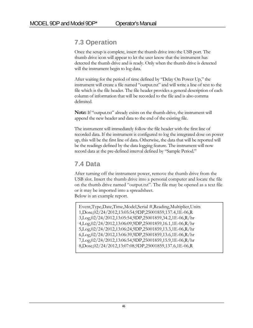
7.4 Data After turning off the instrument power, remove the thumb drive from the USB slot. Insert the thumb drive into a personal computer and locate the file on the thumb drive named “output.txt”. The file may be opened as a text file or it may be imported into a spreadsheet. Below is an example report.
Event,Type,Date,Time,Model,Serial #,Reading,Multiplier,Units
1,Dose,02/24/2012,13:05:54,9DP,25001859,137.4,1E-06,R 3,Log,02/24/2012,13:05:54,9DP,25001859,34.2,1E-06,R/hr 4,Log,02/24/2012,13:06:09,9DP,25001859,16.1,1E-06,R/hr 5,Log,02/24/2012,13:06:24,9DP,25001859,13.3,1E-06,R/hr 6,Log,02/24/2012,13:06:39,9DP,25001859,13.6,1E-06,R/hr 7,Log,02/24/2012,13:06:54,9DP,25001859,15.9,1E-06,R/hr 8,Dose,02/24/2012,13:07:08,9DP,25001859,137.6,1E-06,R
MODEL 9DP and Model 9DP* Operator’s Manual
47
Battery Power
The unit is powered by eight “AA” NIMH (nickle-metal hydride) rechargeable batteries. Use of rechargeable batteries helps to keep operating costs down.
Battery life largely depends upon the LCD backlighting and USB port usage, resulting in a range spanning between 12 to 30 hours. A typical scenario at 60% backlighting and not using the USB port will result in battery life of almost 19 hours. At zero backlighting, as in the case of outdoor operation under good sunlight conditions, with no USB activity, the battery life will attain nearly 30 hours.
It is important to note that this instrument design consumes power even when the instrument is shut off. A very miniscule supply of power is consumed by the microprocessor to allow sensing of the power-on button command by the user. The battery will therefore drain after several months even with no usage.
A wall outlet type battery charger is supplied with the instrument and includes multiple plug adapters to accommodate the different styles used throughout the world. The adaptor is easily changed out by pressing the button labeled “PUSH” on the charger below the plug adaptor, which releases it to be slid out. Then one can slide in the adaptor until it snaps for the style needed.
Section
8
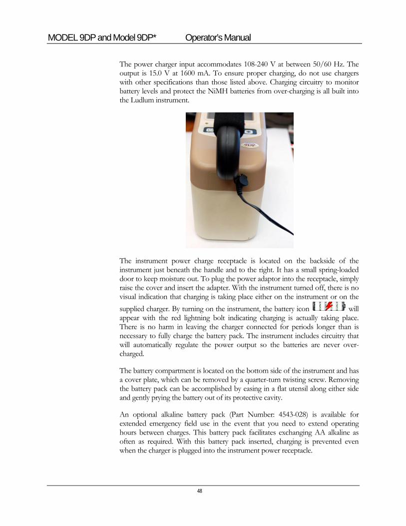
MODEL 9DP and Model 9DP* Operator’s Manual
48
The power charger input accommodates 108-240 V at between 50/60 Hz. The output is 15.0 V at 1600 mA. To ensure proper charging, do not use chargers with other specifications than those listed above. Charging circuitry to monitor battery levels and protect the NiMH batteries from over-charging is all built into the Ludlum instrument.
The instrument power charge receptacle is located on the backside of the instrument just beneath the handle and to the right. It has a small spring-loaded door to keep moisture out. To plug the power adaptor into the receptacle, simply raise the cover and insert the adapter. With the instrument turned off, there is no visual indication that charging is taking place either on the instrument or on the
supplied charger. By turning on the instrument, the battery icon will appear with the red lightning bolt indicating charging is actually taking place. There is no harm in leaving the charger connected for periods longer than is necessary to fully charge the battery pack. The instrument includes circuitry that will automatically regulate the power output so the batteries are never over-charged.
The battery compartment is located on the bottom side of the instrument and has a cover plate, which can be removed by a quarter-turn twisting screw. Removing the battery pack can be accomplished by easing in a flat utensil along either side and gently prying the battery out of its protective cavity.
An optional alkaline battery pack (Part Number: 4543-028) is available for extended emergency field use in the event that you need to extend operating hours between charges. This battery pack facilitates exchanging AA alkaline as often as required. With this battery pack inserted, charging is prevented even when the charger is plugged into the instrument power receptacle.
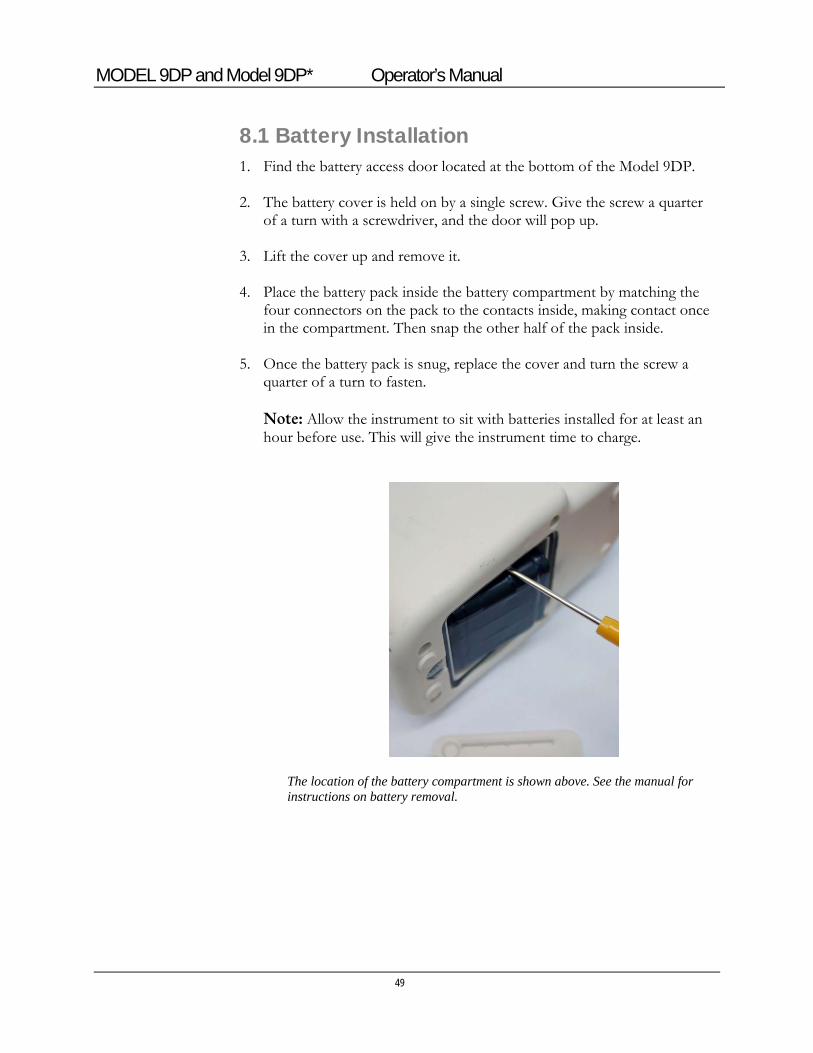
MODEL 9DP and Model 9DP* Operator’s Manual
49
8.1 Battery Installation 1. Find the battery access door located at the bottom of the Model 9DP.
2. The battery cover is held on by a single screw. Give the screw a quarter
of a turn with a screwdriver, and the door will pop up.
3. Lift the cover up and remove it.
4. Place the battery pack inside the battery compartment by matching the four connectors on the pack to the contacts inside, making contact once in the compartment. Then snap the other half of the pack inside.
5. Once the battery pack is snug, replace the cover and turn the screw a quarter of a turn to fasten. Note: Allow the instrument to sit with batteries installed for at least an hour before use. This will give the instrument time to charge.
The location of the battery compartment is shown above. See the manual for instructions on battery removal.
MODEL 9DP and Model 9DP* Operator’s Manual
50
8.2 Battery Test Even when the instrument is turned off, it continues to draw a very miniscule amount of power in order to continually monitor the control panel while waiting for the power-on command. When fully charged, the battery pack in the OFF state will last for several months before needing to be recharged.
A quick check of the battery status can be made by pressing the Power On pushbutton momentarily (see furthest left-hand button on the control panel). The screen should wake up after about four seconds and go through two start-up views before finally settling onto the measurement view. If upon attempting power start-up the LCD remains blank, proceed with charging the instrument as all the power may have already been drained.
Once the measurement view is presented, a battery icon on the lower, left-hand part of the screen is displayed. The battery icon is segmented into five parts with each segment representing 20% of the battery life. The depletion rate will be according to the backlighting and USB consumption as explained earlier in this section. With experience under your operating conditions, you will begin to have a good idea about how long the battery charges last. Dividing that time period by 5 will then approximate the time per cell.
Color coding is employed to indicate battery level. With all five cells colored green, the battery is indicating a full charge or near full charge. As the battery depletes, each succeeding cell beginning on the right going left, changes its color from green to the screen background color, signifying it has emptied. When only two cells remain (40% of battery life), they both turn to yellow to warn the user that time is getting short. When the power level reaches its last segment (20%), the last remaining cell segment will turn from yellow to red. Users are advised to begin shut down fairly soon at this point.
In this final state, once the power level goes below the necessary voltage, the instrument will alert the operator and then automatically shut itself down. This precautionary measure ensures all measurement data and operating parameters are stored properly prior to losing power.
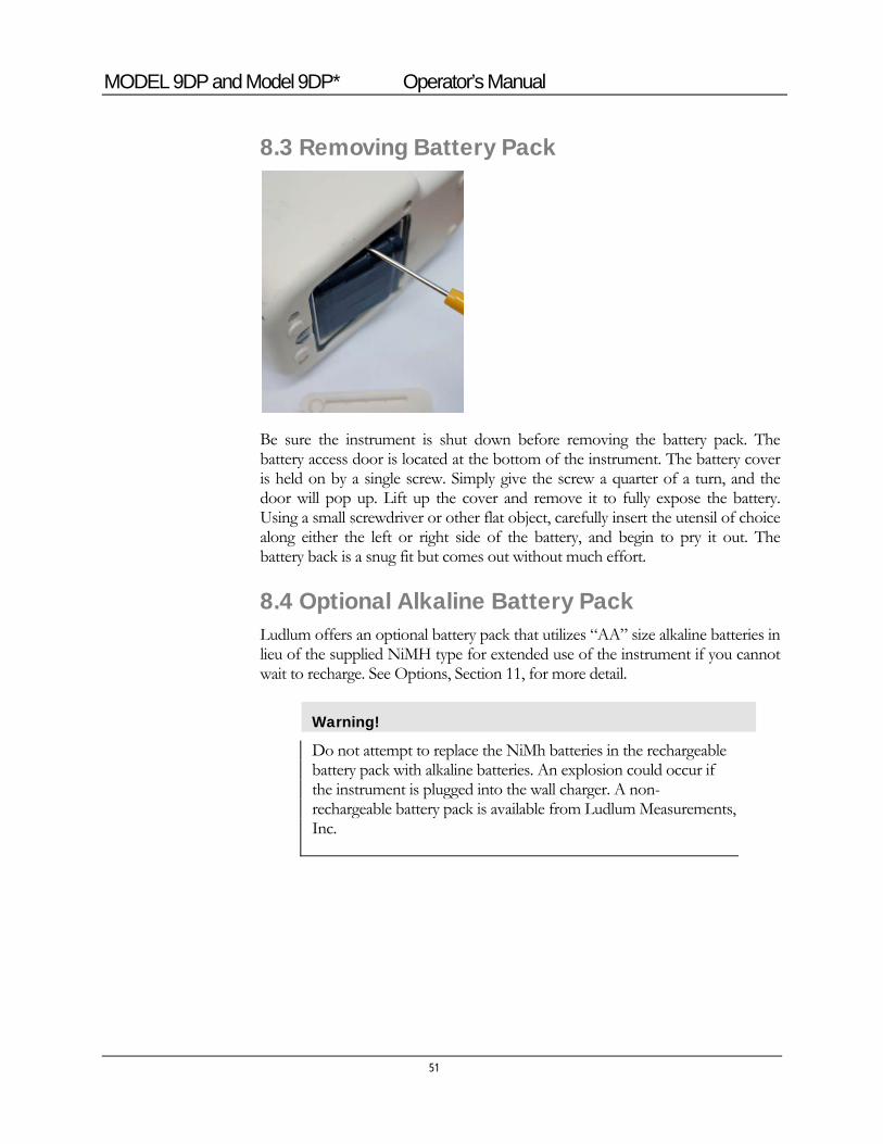
MODEL 9DP and Model 9DP* Operator’s Manual
51
8.3 Removing Battery Pack
Be sure the instrument is shut down before removing the battery pack. The battery access door is located at the bottom of the instrument. The battery cover is held on by a single screw. Simply give the screw a quarter of a turn, and the door will pop up. Lift up the cover and remove it to fully expose the battery. Using a small screwdriver or other flat object, carefully insert the utensil of choice along either the left or right side of the battery, and begin to pry it out. The battery back is a snug fit but comes out without much effort.
8.4 Optional Alkaline Battery Pack Ludlum offers an optional battery pack that utilizes “AA” size alkaline batteries in lieu of the supplied NiMH type for extended use of the instrument if you cannot wait to recharge. See Options, Section 11, for more detail.
Warning!
Do not attempt to replace the NiMh batteries in the rechargeable battery pack with alkaline batteries. An explosion could occur if the instrument is plugged into the wall charger. A non-rechargeable battery pack is available from Ludlum Measurements, Inc.
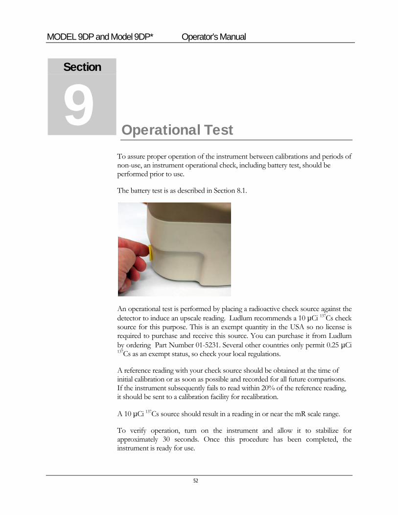
MODEL 9DP and Model 9DP* Operator’s Manual
52
Operational Test
To assure proper operation of the instrument between calibrations and periods of non-use, an instrument operational check, including battery test, should be performed prior to use.
The battery test is as described in Section 8.1.
An operational test is performed by placing a radioactive check source against the detector to induce an upscale reading. Ludlum recommends a 10 µCi 137Cs check source for this purpose. This is an exempt quantity in the USA so no license is required to purchase and receive this source. You can purchase it from Ludlum by ordering Part Number 01-5231. Several other countries only permit 0.25 µCi 137Cs as an exempt status, so check your local regulations.
A reference reading with your check source should be obtained at the time of initial calibration or as soon as possible and recorded for all future comparisons. If the instrument subsequently fails to read within 20% of the reference reading, it should be sent to a calibration facility for recalibration.
A 10 µCi 137Cs source should result in a reading in or near the mR scale range.
To verify operation, turn on the instrument and allow it to stabilize for approximately 30 seconds. Once this procedure has been completed, the instrument is ready for use.
Section
9

MODEL 9DP and Model 9DP* Operator’s Manual
53
Hazardous Material Shipping Classification
The Model 9DP's ion chamber is considered a pressurized vessel, and falls under shipping regulations. In the US, shipping the Model 9DP requires a person properly trained in Hazmat shipping regulations. It is the shipper's responsibility to comply with Department of Transportation (DOT), International Air Transport Association (IATA), International Maritime Dangerous Goods (IMDG), or other regulations. The following is intended as guidance in three broad areas. Domestic (US) Ground Shipments - 49 CFR (Code of Federal Regulations): 1. Keep a copy of the special permit in this section at each location the
Model 9DP ships from. 2. Package the instrument in the original box, or in an equivalent strong
package (32 pounds edge-crush minimum and 200 pounds burst strength) and use at least 2 inches of packing material on all sides of the instrument.
3. Mark the outside of the box with "INSIDE CONTAINER(S) CONFORM WITH DOT-SP 15156.”
4. Generate a “Shippers Declaration for Dangerous Goods,” per DOT 49CFR.
Domestic (US) Air Shipments: 1. Follow the previous steps. 2. Mark the outside of the shipping box with a DOT class 2 non-flammable
gas label (green) and “UN1956.” 3. Keep a copy of the special permit for the carrier or attach to shipping
box. International Shipments: Follow the above steps, but generate the “Shippers Declaration for Dangerous Goods,” per IATA (International Air Transport Association) rules.
Section
10
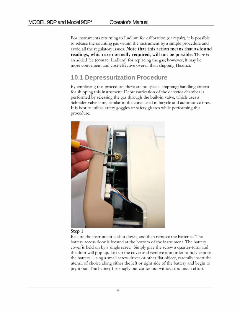
MODEL 9DP and Model 9DP* Operator’s Manual
54
For instruments returning to Ludlum for calibration (or repair), it is possible to release the counting gas within the instrument by a simple procedure and avoid all the regulatory issues. Note that this action means that as-found readings, which are normally required, will not be possible. There is an added fee (contact Ludlum) for replacing the gas; however, it may be more convenient and cost-effective overall than shipping Hazmat.
10.1 Depressurization Procedure By employing this procedure, there are no special shipping/handling criteria for shipping this instrument. Depressurization of the detector chamber is performed by releasing the gas through the built-in valve, which uses a Schrader valve core, similar to the cores used in bicycle and automotive tires. It is best to utilize safety goggles or safety glasses while performing this procedure.
Step 1 Be sure the instrument is shut down, and then remove the batteries. The battery access door is located at the bottom of the instrument. The battery cover is held on by a single screw. Simply give the screw a quarter-turn, and the door will pop up. Lift up the cover and remove it in order to fully expose the battery. Using a small screw driver or other flat object, carefully insert the utensil of choice along either the left or right side of the battery and begin to pry it out. The battery fits snugly but comes out without too much effort.
MODEL 9DP and Model 9DP* Operator’s Manual
55
Step 2 Remove the six screws from the outer perimeter of the bottom case. Be sure to keep the two halves of the instrument together while removing all the screws. Step 3 There is an interconnecting cable running between the upper and lower assemblies, so be sure to not separate the upper and lower half assemblies too far and accidently pull out the cable/connector. By exercising a little care, you will not need to undo the connector to perform this procedure. Slowly separate the upper and lower half of the instrument just 5.1 cm (2 in.) apart and lay it down on its left side. You will see the Schrader valve conveniently positioned on the detector chamber as noted in the picture shown in this section. Step 4 While holding the instrument securely in one hand, use a small pointed device to press down on the valve stem slowly and release all the gas. Be sure to hold the instrument down so that it stays in place while you are releasing the gas. Also be sure to keep your head and eyes clear of the gas exiting the chamber. Continue pressing the valve stem until you stop hearing gas releasing.
Step 5 Carefully rejoin the two half assemblies together, again ensuring the interconnecting cable is all inside the enclosure so it does not get pinched. Re-insert all six screws making certain to not over-tighten them. Finally, insert the battery and battery cover.
10.2 Transportation Special Permit
See following pages for Department of Transportation Special Permit.
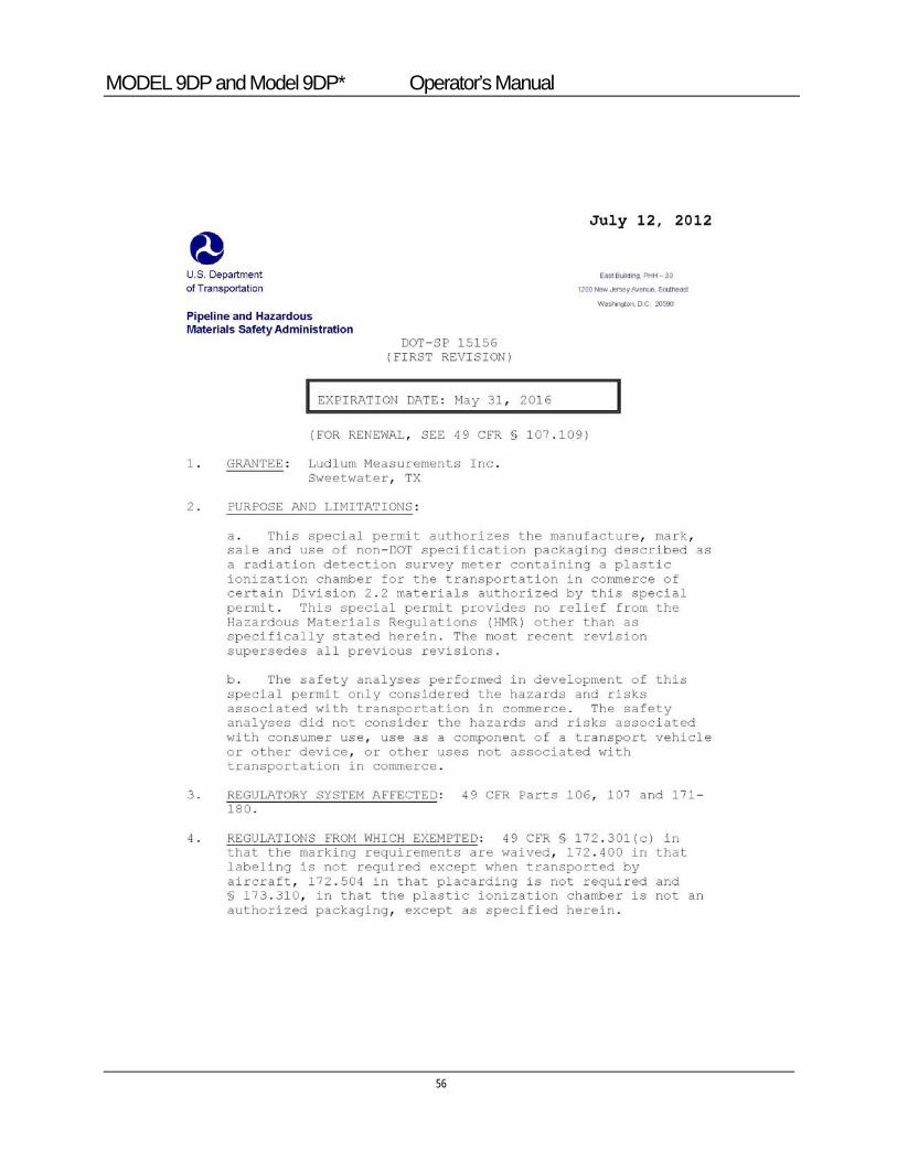
MODEL 9DP and Model 9DP* Operator’s Manual
56
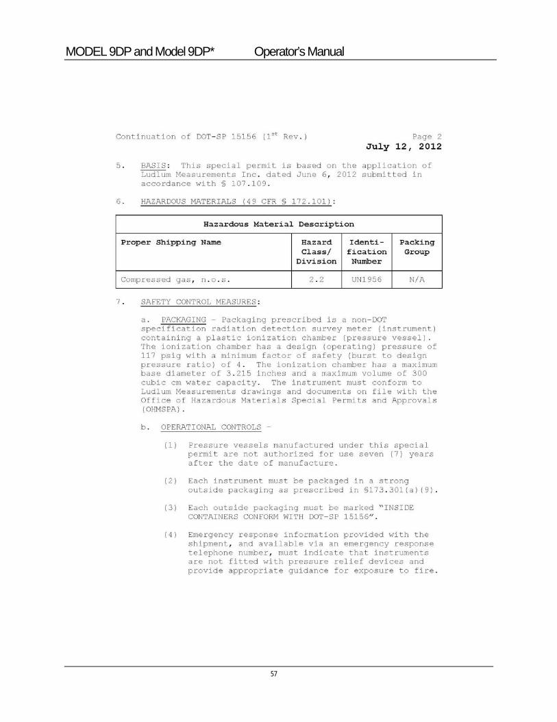
MODEL 9DP and Model 9DP* Operator’s Manual
57
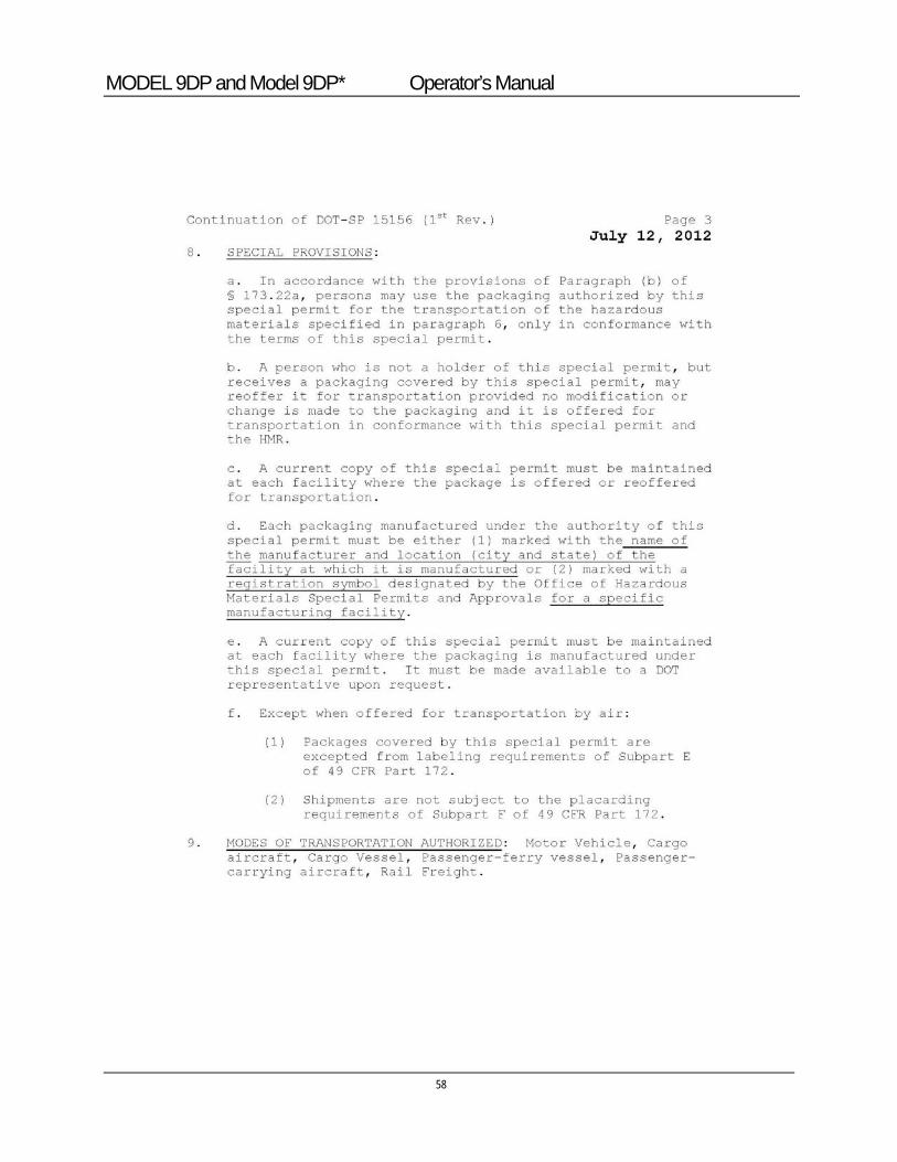
MODEL 9DP and Model 9DP* Operator’s Manual
58
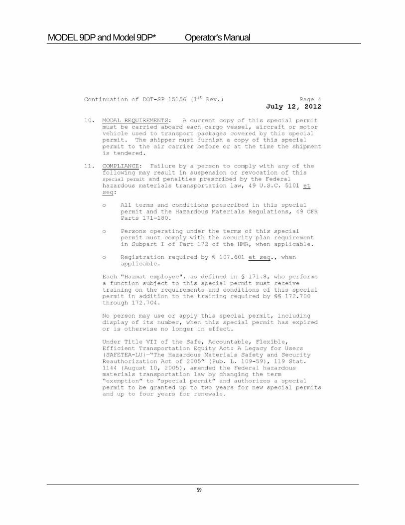
MODEL 9DP and Model 9DP* Operator’s Manual
59
MODEL 9DP and Model 9DP* Operator’s Manual
60
MODEL 9DP and Model 9DP* Operator’s Manual
61
Options
Ludlum offers the following options for the Model 9DP.
11.1 Dimension Interface Kit This kit facilitates connecting any Dimension product to a PC operating under WindowsTM for the purpose of performing setup and instrument calibration. The Ludlum PC software is an extensive program that enables complete control over the setup of any instrument and saving the configuration and calibration detail. This program additionally performs all calibration of the instrument while connected to the PC. This is the only means whereby Dimension products can be calibrated. This kit includes a special USB adapter cable for connection between the PC and the instrument. It does not include any kind of radioactive sources for performing calibrations. Part Number: 4293-763
11.2 Audio Jack Output The Model 9DP provides an audio output via its built-in speaker. An optional audio jack can be purchased to facilitate connection to an audio headset. This option works well whenever the ambient noise levels are too loud or when radioactive clicking sounds may not be desired, such as in an office type environment. This option is factory installed only. Part Number: 4293-891
Section
11
MODEL 9DP and Model 9DP* Operator’s Manual
62
11.3 Alkaline Battery Pack The alkaline battery pack is a convenient way to keep the instrument running for extended periods beyond the battery life of the NiMH pack whenever circumstances warrant this need. Users can swap the NiMH battery pack for a special holder designed for AA size alkaline batteries very quickly in the field. The alkaline battery pack design prevents inadvertent charging, should the charger be plugged into the instrument. Part Number: 4543-028
Warning!
Do not attempt to replace the NiMh batteries in the rechargeable battery pack with alkaline batteries. An explosion could occur if the instrument is plugged into the wall charger. A non-rechargeable battery pack is available from Ludlum Measurements, Inc.
11.4 Check Source Ludlum recommends a 10 µCi 137Cs check source be used for verifying the detector response prior to each use. The source is encapsulated inside of a 2.5 cm x 2.5 mm (1.0 x 0.10 in.) plastic disk. Part Number: 01-5231 Note: Ludlum also offers a 0.25 µCi 137Cs source for countries with lower exempt criteria. This can be purchased under Part Number: 01-5723. Note: Ludlum also offers other sources. Please contact us, one of our representatives, or visit www.ludlums.com for more information.
MODEL 9DP and Model 9DP* Operator’s Manual
63
Safety Considerations and Maintenance 12.1 Environmental Conditions for Normal Use
Indoor or outdoor use
Temperature range of -20 to 50 °C (-4 to 122 °F)
Maximum relative humidity of less than 95% (non-condensing)
Pollution Degree 3 (as defined by IEC 664) (Occurs when conductive pollution or dry nonconductive pollution becomes conductive due to condensation. This is typical of industrial or construction sites.)
12.2 Warning Markings and Symbols
Caution!
The operator or responsible body is cautioned that the protection provided by the equipment may be impaired if the equipment is used in a manner not specified by Ludlum Measurements, Inc.
The Model 9DP Ion Chamber is marked with the following symbols:
CAUTION (per ISO 3864, No. B.3.1) – designates hazardous live voltage and risk of electric shock. During normal use, internal components are hazardous live. This instrument must be isolated or disconnected from the hazardous live voltage before accessing the internal components. This symbol appears on the front panel. Note the following precautions:
Section
12
MODEL 9DP and Model 9DP* Operator’s Manual
Warning!
The operator is strongly cautioned to take the following precautions to avoid contact with internal hazardous live parts that are accessible using a tool: 1. Turn the instrument power OFF and remove the batteries. 2. Allow the instrument to discharge before accessing internal components. The 90-volt wall voltage will require several hours to discharge. It may be discharged using a standard multimeter set to the VDC setting.
The “crossed-out wheelie bin” symbol notifies the consumer that the product is not to be mixed with unsorted municipal waste when discarding; each material must be separated. The symbol is placed on the battery compartment lid. See Section 14, “Recycling,” for further information.
The “CE” mark is used to identify this instrument as being acceptable for use within the European Union.
CAUTION!
While designed to meet regulations, the pressurized chamber of the Model 9DP and 9DP* could potentially explode if dropped or heated excessively (above 80 °C or 176 °F). This is not likely to happen. In drop testing onto concrete, the chamber has survived drops of up to 11.2 m (37 ft). Tests have also shown that the Model 9DP or 9DP* instrument housing will likely contain the explosion. Users are however cautioned to take adequate precautions to avoid these kinds of impacts or temperatures.
Model 9DP and Model 9DP* Operator’s Manual
65
12.3 Cleaning and Maintenance Precautions Instrument maintenance consists of keeping the instrument clean and periodically checking the batteries and calibration. The Model 9DP may be cleaned externally with a damp cloth, using only water as the wetting agent. Do not immerse the instrument in any liquid. Observe the following precautions when cleaning or performing maintenance on the instrument:
1. Turn the instrument OFF and remove the batteries.
2. Wait one hour for the supervisor power to drop below required levels. After one hour has passed, the can may be removed from the chassis.
Note: Before proceeding, the user should wear static protection to prevent accidental static discharge from damaging electronics.
3. Allow the instrument to sit for one minute before cleaning the exterior or accessing any internal components for maintenance.
4. Discharge the wall voltage using a standard multimeter set to the VDC setting, or allow several hours for discharge if the instrument is opened.
5. Disconnect the ribbon cable from the high-voltage board.
6. Using a multimeter, measure the DC voltage between Pins 5 and 9 of the ribbon connector mounted on the high-voltage board. Continue to measure the voltage between the two pins until the voltage reads approximately 0 V.
7. Use a low-pressure air source or a non-static brush to gently clear away any contamination.
MODEL 9DP and Model 9DP* Operator’s Manual
66
12.4 Maintenance RECALIBRATION
Recalibration should be accomplished after maintenance or adjustments have been performed on the instrument. Recalibration is not normally required following instrument cleaning, desiccant servicing, or battery replacement.
Note:
Ludlum Measurements, Inc. recommends recalibration at intervals no greater than one year. Check the appropriate regulations to determine required recalibration intervals.
Ludlum Measurements offers a full-service repair and calibration department. We not only repair and calibrate our own instruments, but also most other manufacturers’ instruments. Calibration procedures are available upon request for customers who choose to calibrate their own instruments.
If the instrument is stored in an area with high humidity, rapid changes in temperature should be avoided. A storage cabinet with a light bulb inside is one means of keeping the instrument in a slightly warmer than ambient temperature environment, in order to prevent problems from rapid changes in temperature and humidity.
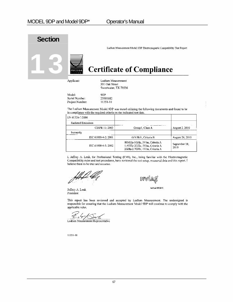
MODEL 9DP and Model 9DP* Operator’s Manual
67
Section
13
MODEL 9DP and Model 9DP* Operator’s Manual
Recycling udlum Measurements, Inc. supports the recycling of the electronics products it produces for the purpose of protecting the environment and to comply with all regional, national, and international agencies that promote economically and environmentally sustainable recycling
systems. To this end, Ludlum Measurements, Inc. strives to supply the consumer of its goods with information regarding reuse and recycling of the many different types of materials used in its products. With many different agencies – public and private – involved in this pursuit, it becomes evident that a myriad of methods can be used in the process of recycling. Therefore, Ludlum Measurements, Inc. does not suggest one particular method over another, but simply desires to inform its consumers of the range of recyclable materials present in its products, so that the user will have flexibility in following all local and federal laws.
The following types of recyclable materials are present in Ludlum Measurements, Inc. electronics products and should be recycled separately. The list is not all-inclusive, nor does it suggest that all materials are present in each piece of equipment: batteries, glass, aluminum and stainless steel, circuit boards, plastics, and liquid crystal display (LCD).
Ludlum Measurements, Inc. products, which have been placed on the market after August 13, 2005, have been labeled with a symbol recognized internationally as the “crossed-out wheelie bin.” This notifies the consumer that the product is not to be mixed with unsorted municipal waste when discarding; each material must be separated. The symbol will be placed near the AC receptacle, except for portable equipment where it will be placed on the battery lid.
The symbol appears as such:
Section
14 L