Embed Size (px)
DESCRIPTION
a document
Citation preview
Uttar Pradesh Power Transmission Corporation Ltd.
Tender Document for Construction
of 132/33 Kv Substation 132/33KV Kursato (Varanasi)
against Tender Specification ESD - 385
On Turnkey Basis as
EPC Contract
Document for EPC Turnkey Bid
Electricity Substation Design Circle-II
Uttar Pradesh Power Transmission Corporation Limited, 13TH, FLOOR, SHAKTI BHAWAN EXTENSION,
14-ASHOK MARG, LUCKNOW-226001
Location :: Lucknow; Uploading Date And Time ::Friday, February 13, 2015
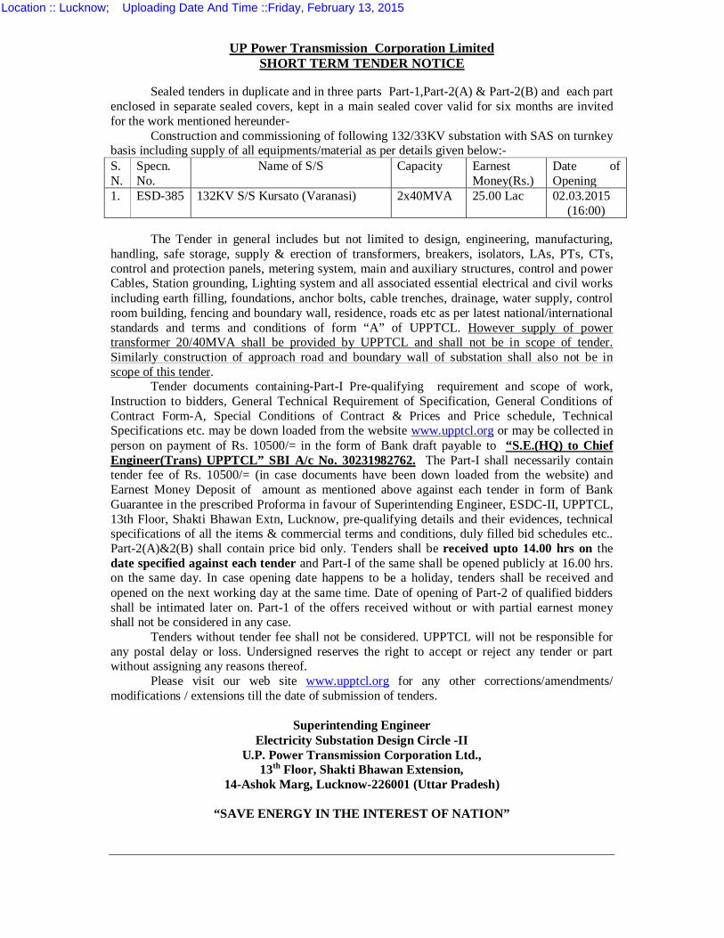
UP Power Transmission Corporation Limited SHORT TERM TENDER NOTICE
Sealed tenders in duplicate and in three parts Part-1,Part-2(A) & Part-2(B) and each part enclosed in separate sealed covers, kept in a main sealed cover valid for six months are invited for the work mentioned hereunder-
Construction and commissioning of following 132/33KV substation with SAS on turnkey basis including supply of all equipments/material as per details given below:- S. N.
Specn. No.
Name of S/S Capacity Earnest Money(Rs.)
Date of Opening
1. ESD-385 132KV S/S Kursato (Varanasi)
2x40MVA
25.00 Lac 02.03.2015 (16:00)
The Tender in general includes but not limited to design, engineering, manufacturing, handling, safe storage, supply & erection of transformers, breakers, isolators, LAs, PTs, CTs, control and protection panels, metering system, main and auxiliary structures, control and power Cables, Station grounding, Lighting system and all associated essential electrical and civil works including earth filling, foundations, anchor bolts, cable trenches, drainage, water supply, control room building, fencing and boundary wall, residence, roads etc as per latest national/international standards and terms and conditions of form “A” of UPPTCL. However supply of power transformer 20/40MVA shall be provided by UPPTCL and shall not be in scope of tender. Similarly construction of approach road and boundary wall of substation shall also not be in scope of this tender.
Tender documents containing-Part-I Pre-qualifying requirement and scope of work, Instruction to bidders, General Technical Requirement of Specification, General Conditions of Contract Form-A, Special Conditions of Contract & Prices and Price schedule, Technical Specifications etc. may be down loaded from the website www.upptcl.org or may be collected in person on payment of Rs. 10500/= in the form of Bank draft payable to “S.E.(HQ) to Chief Engineer(Trans) UPPTCL” SBI A/c No. 30231982762. The Part-I shall necessarily contain tender fee of Rs. 10500/= (in case documents have been down loaded from the website) and Earnest Money Deposit of amount as mentioned above against each tender in form of Bank Guarantee in the prescribed Proforma in favour of Superintending Engineer, ESDC-II, UPPTCL, 13th Floor, Shakti Bhawan Extn, Lucknow, pre-qualifying details and their evidences, technical specifications of all the items & commercial terms and conditions, duly filled bid schedules etc.. Part-2(A)&2(B) shall contain price bid only. Tenders shall be received upto 14.00 hrs on the date specified against each tender and Part-I of the same shall be opened publicly at 16.00 hrs. on the same day. In case opening date happens to be a holiday, tenders shall be received and opened on the next working day at the same time. Date of opening of Part-2 of qualified bidders shall be intimated later on. Part-1 of the offers received without or with partial earnest money shall not be considered in any case.
Tenders without tender fee shall not be considered. UPPTCL will not be responsible for any postal delay or loss. Undersigned reserves the right to accept or reject any tender or part without assigning any reasons thereof.
Please visit our web site www.upptcl.org for any other corrections/amendments/ modifications / extensions till the date of submission of tenders.
Superintending Engineer
Electricity Substation Design Circle -II U.P. Power Transmission Corporation Ltd.,
13th Floor, Shakti Bhawan Extension, 14-Ashok Marg, Lucknow-226001 (Uttar Pradesh)
“SAVE ENERGY IN THE INTEREST OF NATION”
Location :: Lucknow; Uploading Date And Time ::Friday, February 13, 2015
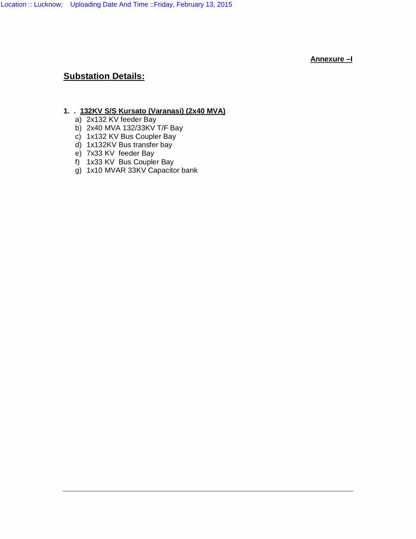
Annexure –I
Substation Details: 1. . 132KV S/S Kursato (Varanasi) (2x40 MVA)
a) 2x132 KV feeder Bay b) 2x40 MVA 132/33KV T/F Bay c) 1x132 KV Bus Coupler Bay d) 1x132KV Bus transfer bay e) 7x33 KV feeder Bay f) 1x33 KV Bus Coupler Bay g) 1x10 MVAR 33KV Capacitor bank
Location :: Lucknow; Uploading Date And Time ::Friday, February 13, 2015
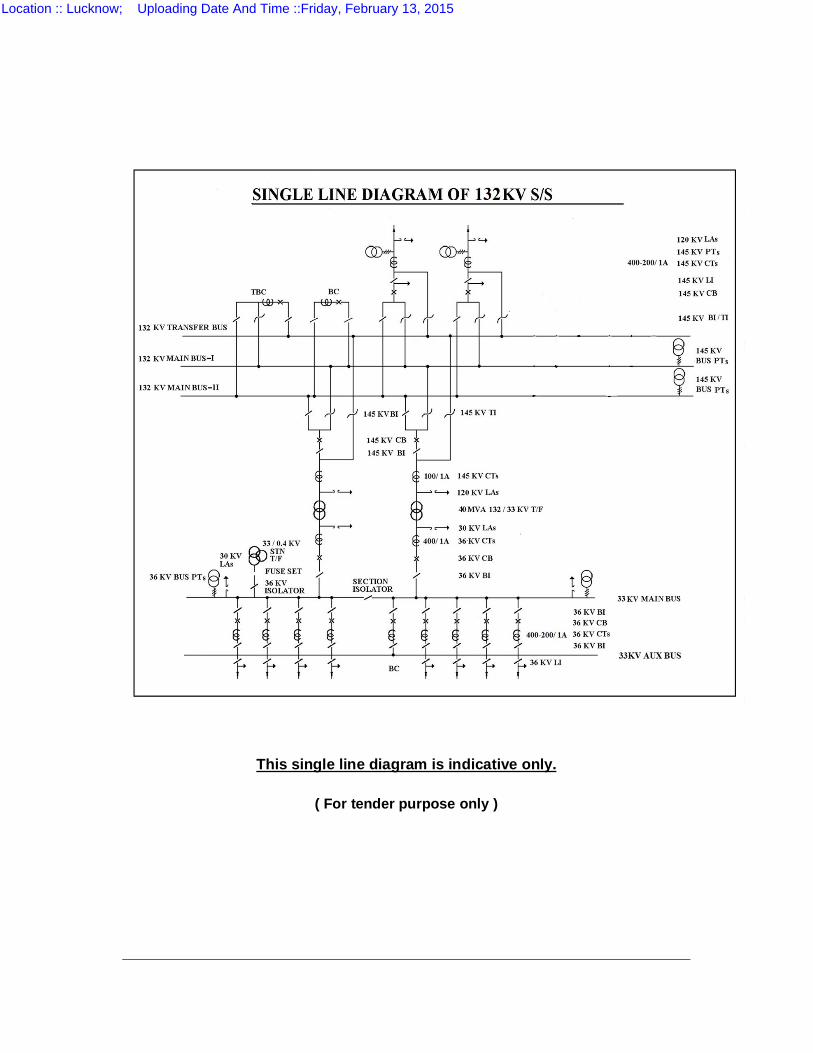
This single line diagram is indicative only.
( For tender purpose only )
Location :: Lucknow; Uploading Date And Time ::Friday, February 13, 2015
TABLE OF CONTENTS
SECTION I PREQUALIFICATION REQUIREMENT & SCOPE OF WORK
SECTION II INSTRUCTIONS TO BIDDERS
SECTION III SPECIAL CONDITIONS
SECTION IV TECHNICAL SPECIFICATIONS FOR HANDLING, ERECTION, TESTING AND COMMISSIONING
SECTION V GENERAL TECHNICAL REQUIREMENTS OF SPECIFICATIONS SECTION VI FORM –A
DRAWINGS APPENDIX A APPLICATION PROFORMA (FORMS 0 TO 10) APPENDIX B BID SCHEDULE (SCHEDULE A TO R) SECTION VII TECHNICAL SPECIFICATIONS OF EQUIPMENTS AND
MATERIAL SECTION VIII CIVIL WORKS
Location :: Lucknow; Uploading Date And Time ::Friday, February 13, 2015
SECTION I
PREQUALIFICATION REQUIREMENT & SCOPE OF WORK
1.0 GENERAL
2.0 WORK DESCRIPTION
3.0 SCOPE OF WORKS
4.0 QUALIFICATION OF THE BIDDER 5.0 COMPLETION PERIOD 6.0 LIQUIDATED DAMAGES FOR DELAYS IN SUPPLY / COMPLETION
PERIOD 7.0 TERMS AND CONDITIONS 8.0 ELIGIBLE APPLICANTS
Location :: Lucknow; Uploading Date And Time ::Friday, February 13, 2015
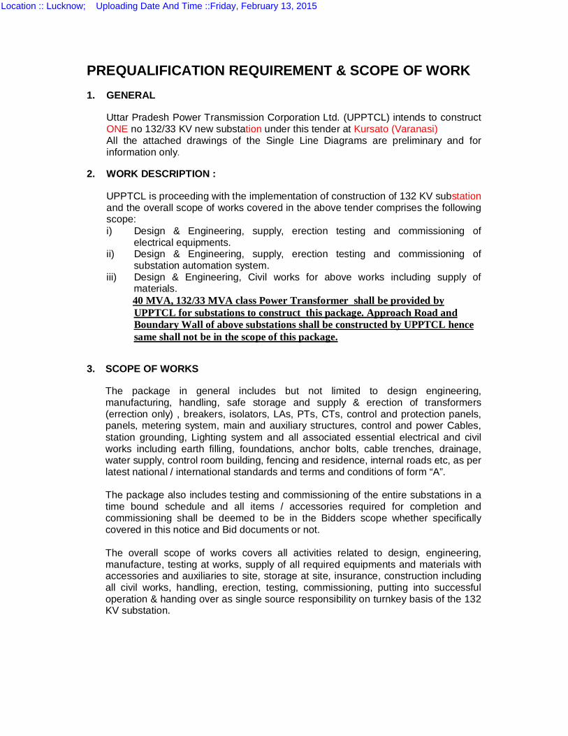
PREQUALIFICATION REQUIREMENT & SCOPE OF WORK 1. GENERAL
Uttar Pradesh Power Transmission Corporation Ltd. (UPPTCL) intends to construct ONE no 132/33 KV new substation under this tender at Kursato (Varanasi) All the attached drawings of the Single Line Diagrams are preliminary and for information only.
2. WORK DESCRIPTION :
UPPTCL is proceeding with the implementation of construction of 132 KV substation and the overall scope of works covered in the above tender comprises the following scope: i) Design & Engineering, supply, erection testing and commissioning of
electrical equipments. ii) Design & Engineering, supply, erection testing and commissioning of
substation automation system. iii) Design & Engineering, Civil works for above works including supply of
materials. 40 MVA, 132/33 MVA class Power Transformer shall be provided by
UPPTCL for substations to construct this package. Approach Road and Boundary Wall of above substations shall be constructed by UPPTCL hence same shall not be in the scope of this package.
3. SCOPE OF WORKS
The package in general includes but not limited to design engineering, manufacturing, handling, safe storage and supply & erection of transformers (errection only) , breakers, isolators, LAs, PTs, CTs, control and protection panels, panels, metering system, main and auxiliary structures, control and power Cables, station grounding, Lighting system and all associated essential electrical and civil works including earth filling, foundations, anchor bolts, cable trenches, drainage, water supply, control room building, fencing and residence, internal roads etc, as per latest national / international standards and terms and conditions of form “A”.
The package also includes testing and commissioning of the entire substations in a
time bound schedule and all items / accessories required for completion and commissioning shall be deemed to be in the Bidders scope whether specifically covered in this notice and Bid documents or not.
The overall scope of works covers all activities related to design, engineering, manufacture, testing at works, supply of all required equipments and materials with accessories and auxiliaries to site, storage at site, insurance, construction including all civil works, handling, erection, testing, commissioning, putting into successful operation & handing over as single source responsibility on turnkey basis of the 132 KV substation.
Location :: Lucknow; Uploading Date And Time ::Friday, February 13, 2015
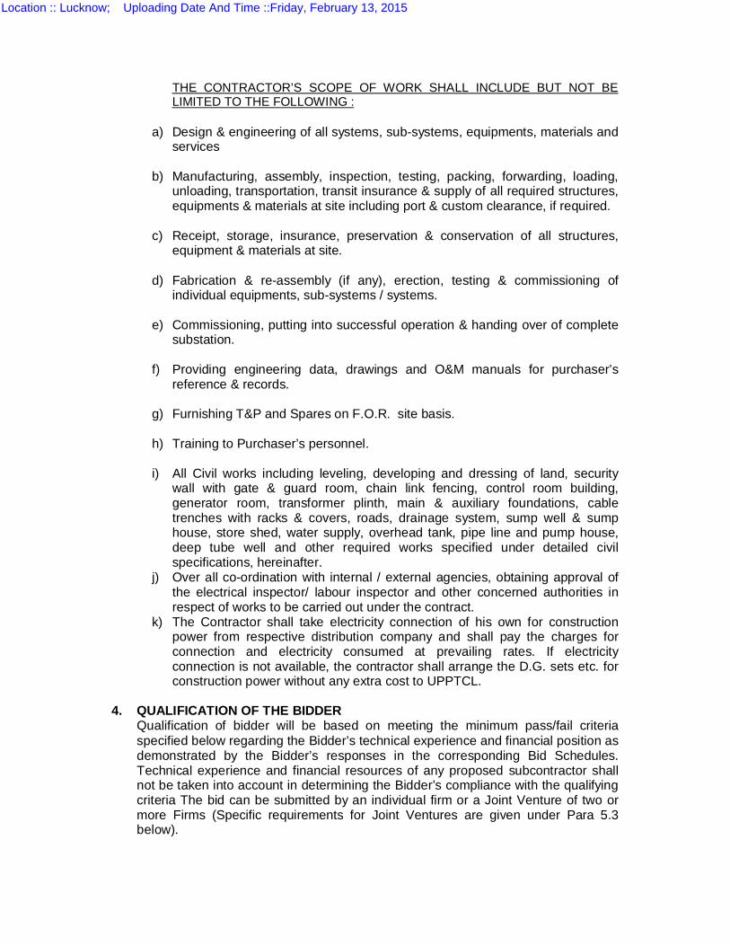
THE CONTRACTOR’S SCOPE OF WORK SHALL INCLUDE BUT NOT BE LIMITED TO THE FOLLOWING :
a) Design & engineering of all systems, sub-systems, equipments, materials and
services
b) Manufacturing, assembly, inspection, testing, packing, forwarding, loading, unloading, transportation, transit insurance & supply of all required structures, equipments & materials at site including port & custom clearance, if required.
c) Receipt, storage, insurance, preservation & conservation of all structures,
equipment & materials at site.
d) Fabrication & re-assembly (if any), erection, testing & commissioning of individual equipments, sub-systems / systems.
e) Commissioning, putting into successful operation & handing over of complete
substation.
f) Providing engineering data, drawings and O&M manuals for purchaser’s reference & records.
g) Furnishing T&P and Spares on F.O.R. site basis.
h) Training to Purchaser’s personnel.
i) All Civil works including leveling, developing and dressing of land, security
wall with gate & guard room, chain link fencing, control room building, generator room, transformer plinth, main & auxiliary foundations, cable trenches with racks & covers, roads, drainage system, sump well & sump house, store shed, water supply, overhead tank, pipe line and pump house, deep tube well and other required works specified under detailed civil specifications, hereinafter.
j) Over all co-ordination with internal / external agencies, obtaining approval of the electrical inspector/ labour inspector and other concerned authorities in respect of works to be carried out under the contract.
k) The Contractor shall take electricity connection of his own for construction power from respective distribution company and shall pay the charges for connection and electricity consumed at prevailing rates. If electricity connection is not available, the contractor shall arrange the D.G. sets etc. for construction power without any extra cost to UPPTCL.
4. QUALIFICATION OF THE BIDDER
Qualification of bidder will be based on meeting the minimum pass/fail criteria specified below regarding the Bidder’s technical experience and financial position as demonstrated by the Bidder’s responses in the corresponding Bid Schedules. Technical experience and financial resources of any proposed subcontractor shall not be taken into account in determining the Bidder’s compliance with the qualifying criteria The bid can be submitted by an individual firm or a Joint Venture of two or more Firms (Specific requirements for Joint Ventures are given under Para 5.3 below).
Location :: Lucknow; Uploading Date And Time ::Friday, February 13, 2015
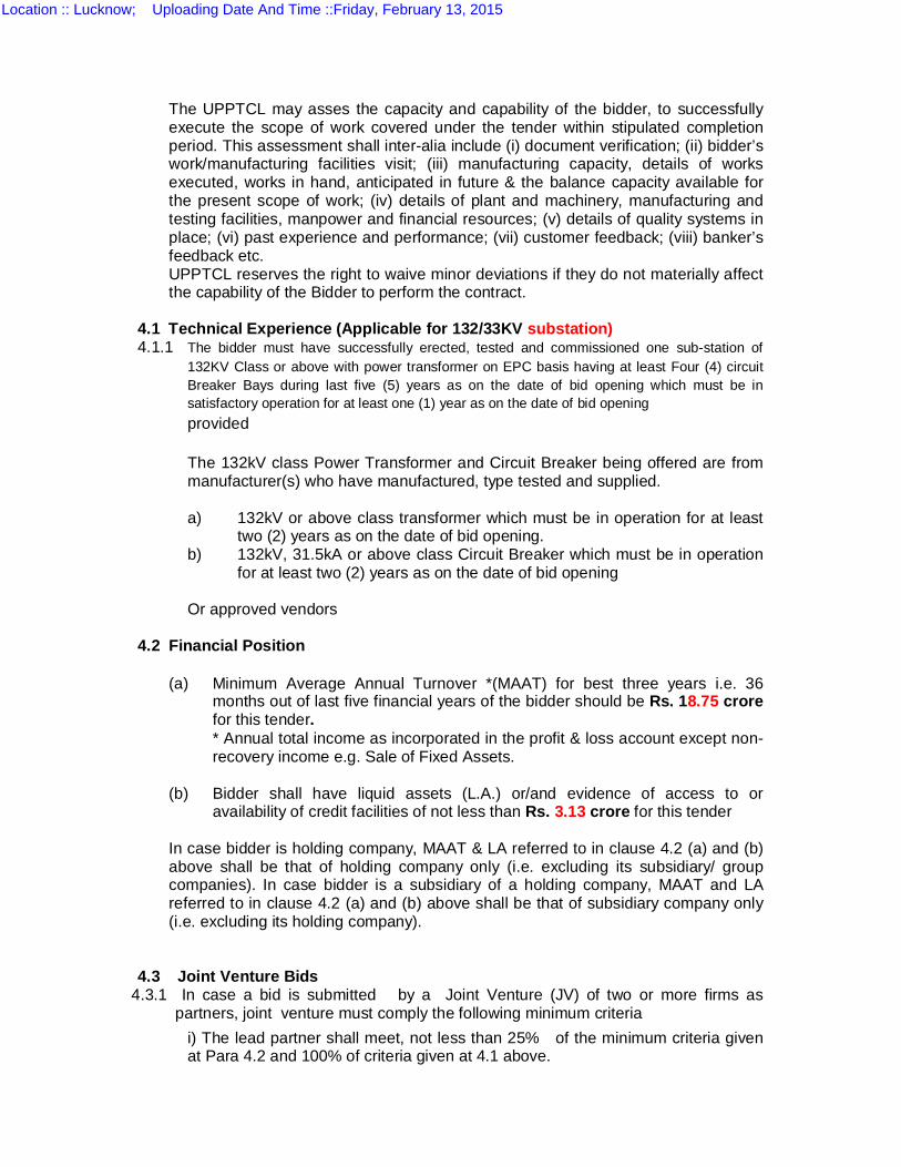
The UPPTCL may asses the capacity and capability of the bidder, to successfully execute the scope of work covered under the tender within stipulated completion period. This assessment shall inter-alia include (i) document verification; (ii) bidder’s work/manufacturing facilities visit; (iii) manufacturing capacity, details of works executed, works in hand, anticipated in future & the balance capacity available for the present scope of work; (iv) details of plant and machinery, manufacturing and testing facilities, manpower and financial resources; (v) details of quality systems in place; (vi) past experience and performance; (vii) customer feedback; (viii) banker’s feedback etc. UPPTCL reserves the right to waive minor deviations if they do not materially affect the capability of the Bidder to perform the contract.
4.1 Technical Experience (Applicable for 132/33KV substation) 4.1.1 The bidder must have successfully erected, tested and commissioned one sub-station of
132KV Class or above with power transformer on EPC basis having at least Four (4) circuit Breaker Bays during last five (5) years as on the date of bid opening which must be in satisfactory operation for at least one (1) year as on the date of bid opening provided
The 132kV class Power Transformer and Circuit Breaker being offered are from manufacturer(s) who have manufactured, type tested and supplied. a) 132kV or above class transformer which must be in operation for at least
two (2) years as on the date of bid opening. b) 132kV, 31.5kA or above class Circuit Breaker which must be in operation
for at least two (2) years as on the date of bid opening
Or approved vendors 4.2 Financial Position
(a) Minimum Average Annual Turnover *(MAAT) for best three years i.e. 36 months out of last five financial years of the bidder should be Rs. 18.75 crore for this tender. * Annual total income as incorporated in the profit & loss account except non-recovery income e.g. Sale of Fixed Assets.
(b) Bidder shall have liquid assets (L.A.) or/and evidence of access to or
availability of credit facilities of not less than Rs. 3.13 crore for this tender
In case bidder is holding company, MAAT & LA referred to in clause 4.2 (a) and (b) above shall be that of holding company only (i.e. excluding its subsidiary/ group companies). In case bidder is a subsidiary of a holding company, MAAT and LA referred to in clause 4.2 (a) and (b) above shall be that of subsidiary company only (i.e. excluding its holding company).
4.3 Joint Venture Bids
4.3.1 In case a bid is submitted by a Joint Venture (JV) of two or more firms as partners, joint venture must comply the following minimum criteria
i) The lead partner shall meet, not less than 25% of the minimum criteria given at Para 4.2 and 100% of criteria given at 4.1 above.
Location :: Lucknow; Uploading Date And Time ::Friday, February 13, 2015
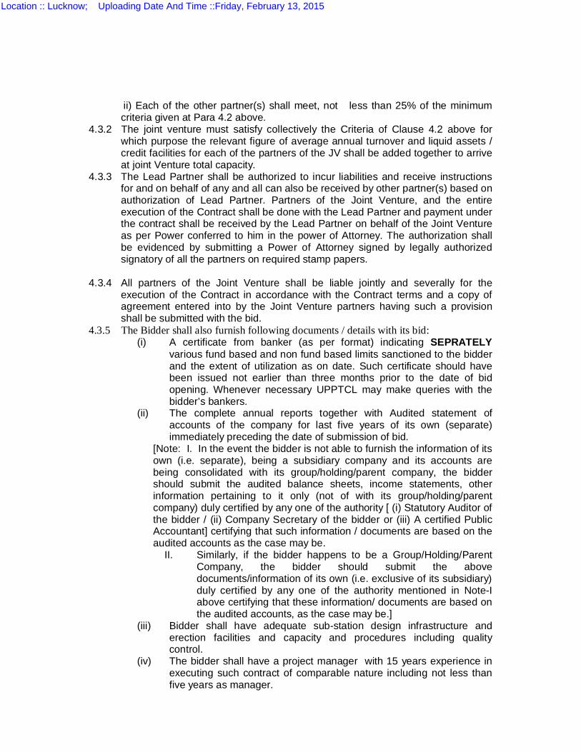
ii) Each of the other partner(s) shall meet, not less than 25% of the minimum criteria given at Para 4.2 above.
4.3.2 The joint venture must satisfy collectively the Criteria of Clause 4.2 above for which purpose the relevant figure of average annual turnover and liquid assets / credit facilities for each of the partners of the JV shall be added together to arrive at joint Venture total capacity.
4.3.3 The Lead Partner shall be authorized to incur liabilities and receive instructions for and on behalf of any and all can also be received by other partner(s) based on authorization of Lead Partner. Partners of the Joint Venture, and the entire execution of the Contract shall be done with the Lead Partner and payment under the contract shall be received by the Lead Partner on behalf of the Joint Venture as per Power conferred to him in the power of Attorney. The authorization shall be evidenced by submitting a Power of Attorney signed by legally authorized signatory of all the partners on required stamp papers.
4.3.4 All partners of the Joint Venture shall be liable jointly and severally for the
execution of the Contract in accordance with the Contract terms and a copy of agreement entered into by the Joint Venture partners having such a provision shall be submitted with the bid.
4.3.5 The Bidder shall also furnish following documents / details with its bid: (i) A certificate from banker (as per format) indicating SEPRATELY
various fund based and non fund based limits sanctioned to the bidder and the extent of utilization as on date. Such certificate should have been issued not earlier than three months prior to the date of bid opening. Whenever necessary UPPTCL may make queries with the bidder’s bankers.
(ii) The complete annual reports together with Audited statement of accounts of the company for last five years of its own (separate) immediately preceding the date of submission of bid.
[Note: I. In the event the bidder is not able to furnish the information of its own (i.e. separate), being a subsidiary company and its accounts are being consolidated with its group/holding/parent company, the bidder should submit the audited balance sheets, income statements, other information pertaining to it only (not of with its group/holding/parent company) duly certified by any one of the authority [ (i) Statutory Auditor of the bidder / (ii) Company Secretary of the bidder or (iii) A certified Public Accountant] certifying that such information / documents are based on the audited accounts as the case may be.
II. Similarly, if the bidder happens to be a Group/Holding/Parent Company, the bidder should submit the above documents/information of its own (i.e. exclusive of its subsidiary) duly certified by any one of the authority mentioned in Note-I above certifying that these information/ documents are based on the audited accounts, as the case may be.]
(iii) Bidder shall have adequate sub-station design infrastructure and erection facilities and capacity and procedures including quality control.
(iv) The bidder shall have a project manager with 15 years experience in executing such contract of comparable nature including not less than five years as manager.
Location :: Lucknow; Uploading Date And Time ::Friday, February 13, 2015
4.4 QUALIFICATION CRITERION
4.4.1 Prequalification will be based on meeting all the following minimum pass/fail criteria regarding the Applicant’s general and particular experience, personnel and equipment capabilities, and financial position, as established by the Applicant’s responses in the forms attached to the Letter of Application (specific requirements for joint ventures are given specifically).
4.4.2 General Experience: The Applicant shall meet the minimum criteria outlined in Section I of the Invitation for Prequalification, for the tender.
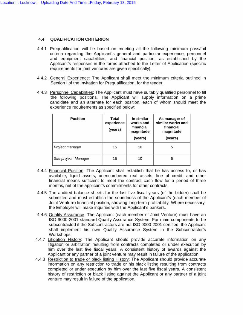
4.4.3 Personnel Capabilities: The Applicant must have suitably qualified personnel to fill the following positions. The Applicant will supply information on a prime candidate and an alternate for each position, each of whom should meet the experience requirements as specified below:
Position Total experience
(years)
In similar works and financial
magnitude
(years)
As manager of similar works and
financial magnitude
(years)
Project manager 15 10 5
Site project Manager 15 10 5
4.4.4 Financial Position: The Applicant shall establish that he has access to, or has available, liquid assets, unencumbered real assets, line of credit, and other financial means sufficient to meet the contract cash flow for a period of three months, net of the applicant’s commitments for other contracts, 4.4.5 The audited balance sheets for the last five fiscal years (of the bidder) shall be submitted and must establish the soundness of the Applicant’s (each member of Joint Venture) financial position, showing long-term profitability. Where necessary, the Employer will make inquiries with the Applicant’s bankers. 4.4.6 Quality Assurance: The Applicant (each member of Joint Venture) must have an ISO 9000-2001 standard Quality Assurance System. For main components to be subcontracted if the Subcontractors are not ISO 9000-2001 certified, the Applicant shall implement his own Quality Assurance System in the Subcontractor’s Workshops.
4.4.7 Litigation History: The Applicant should provide accurate information on any litigation or arbitration resulting from contracts completed or under execution by him over the last five fiscal years. A consistent history of awards against the Applicant or any partner of a joint venture may result in failure of the application.
4.4.8 Restriction to trade or black listing History: The Applicant should provide accurate information on any restriction to trade or his black listing resulting from contracts completed or under execution by him over the last five fiscal years. A consistent history of restriction or black listing against the Applicant or any partner of a joint venture may result in failure of the application.
Location :: Lucknow; Uploading Date And Time ::Friday, February 13, 2015
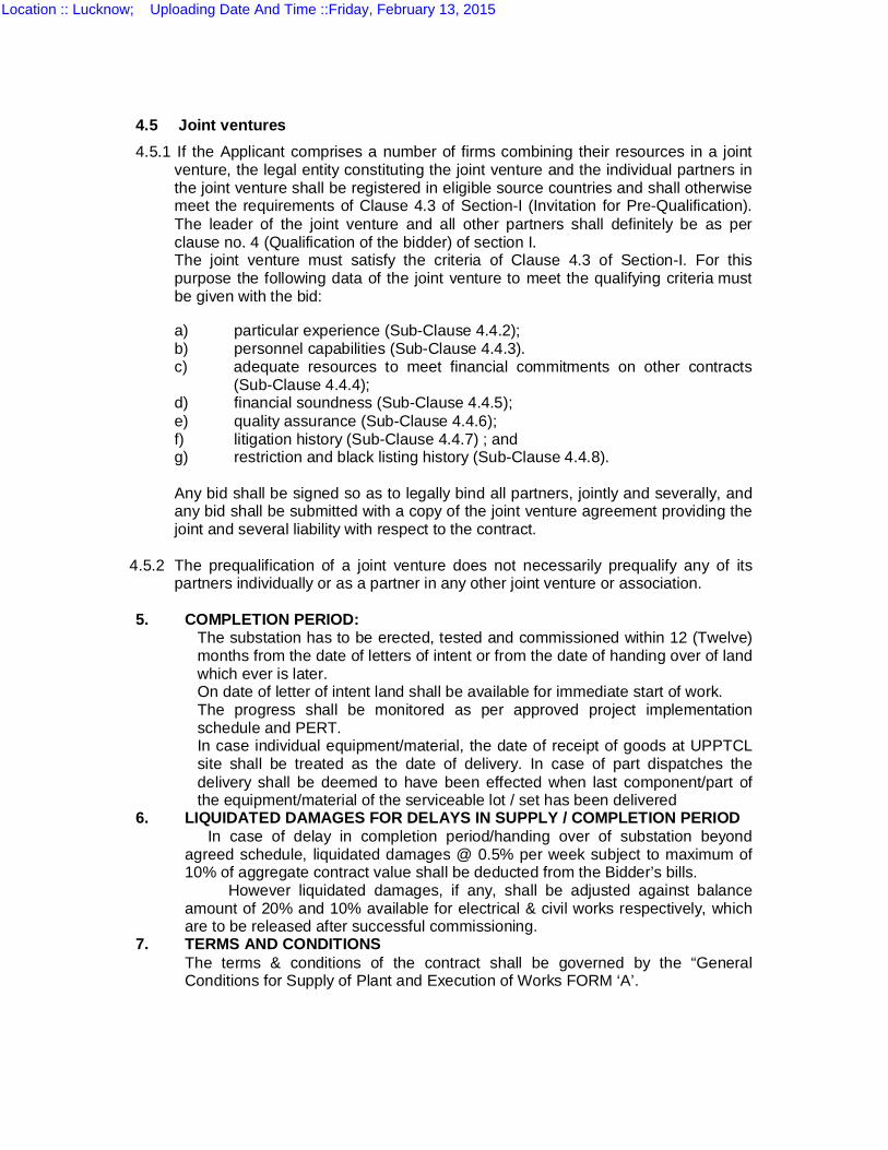
4.5 Joint ventures
4.5.1 If the Applicant comprises a number of firms combining their resources in a joint venture, the legal entity constituting the joint venture and the individual partners in the joint venture shall be registered in eligible source countries and shall otherwise meet the requirements of Clause 4.3 of Section-I (Invitation for Pre-Qualification). The leader of the joint venture and all other partners shall definitely be as per clause no. 4 (Qualification of the bidder) of section I. The joint venture must satisfy the criteria of Clause 4.3 of Section-I. For this purpose the following data of the joint venture to meet the qualifying criteria must be given with the bid:
a) particular experience (Sub-Clause 4.4.2); b) personnel capabilities (Sub-Clause 4.4.3). c) adequate resources to meet financial commitments on other contracts
(Sub-Clause 4.4.4); d) financial soundness (Sub-Clause 4.4.5); e) quality assurance (Sub-Clause 4.4.6); f) litigation history (Sub-Clause 4.4.7) ; and g) restriction and black listing history (Sub-Clause 4.4.8). Any bid shall be signed so as to legally bind all partners, jointly and severally, and any bid shall be submitted with a copy of the joint venture agreement providing the joint and several liability with respect to the contract.
4.5.2 The prequalification of a joint venture does not necessarily prequalify any of its partners individually or as a partner in any other joint venture or association.
5. COMPLETION PERIOD: The substation has to be erected, tested and commissioned within 12 (Twelve)
months from the date of letters of intent or from the date of handing over of land which ever is later.
On date of letter of intent land shall be available for immediate start of work. The progress shall be monitored as per approved project implementation
schedule and PERT. In case individual equipment/material, the date of receipt of goods at UPPTCL
site shall be treated as the date of delivery. In case of part dispatches the delivery shall be deemed to have been effected when last component/part of the equipment/material of the serviceable lot / set has been delivered
6. LIQUIDATED DAMAGES FOR DELAYS IN SUPPLY / COMPLETION PERIOD In case of delay in completion period/handing over of substation beyond agreed schedule, liquidated damages @ 0.5% per week subject to maximum of 10% of aggregate contract value shall be deducted from the Bidder’s bills. However liquidated damages, if any, shall be adjusted against balance amount of 20% and 10% available for electrical & civil works respectively, which are to be released after successful commissioning.
7. TERMS AND CONDITIONS The terms & conditions of the contract shall be governed by the “General Conditions for Supply of Plant and Execution of Works FORM ‘A’.
Location :: Lucknow; Uploading Date And Time ::Friday, February 13, 2015
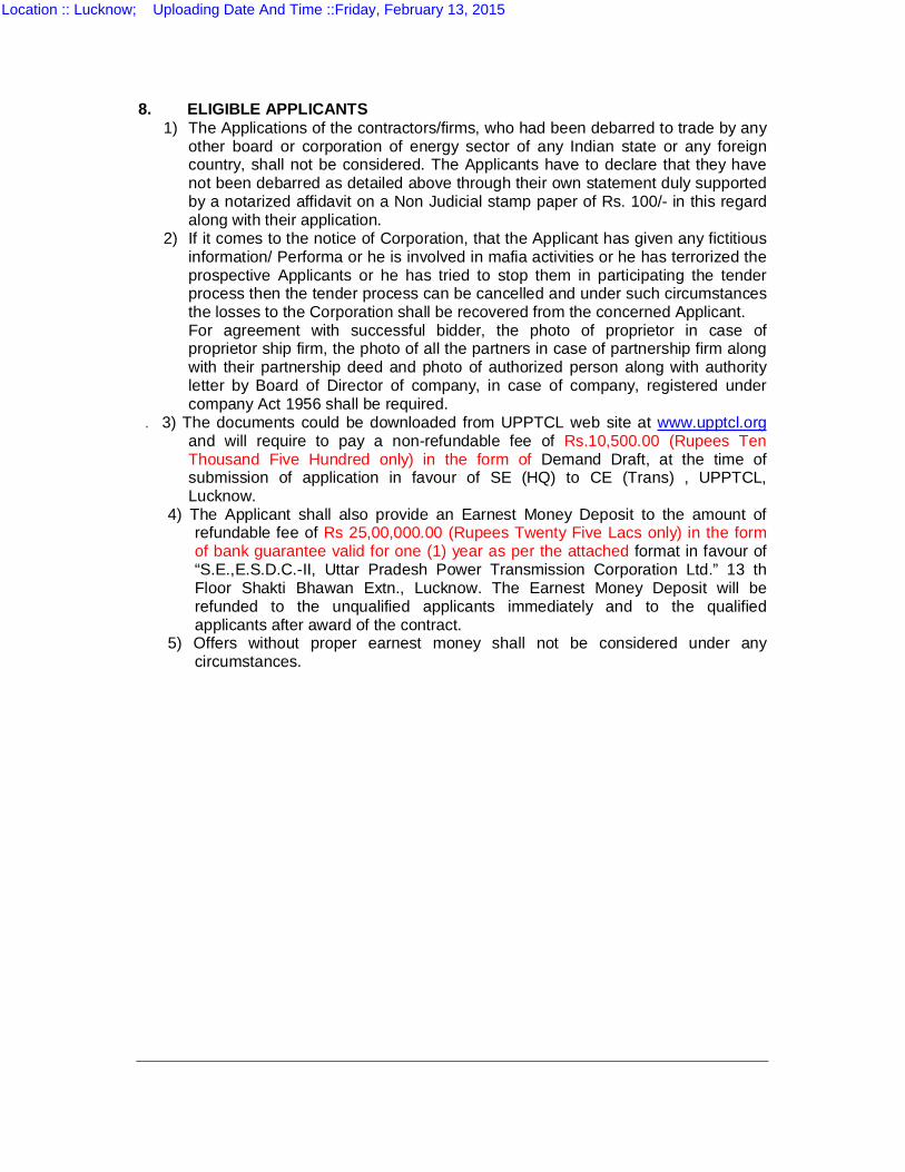
8. ELIGIBLE APPLICANTS 1) The Applications of the contractors/firms, who had been debarred to trade by any
other board or corporation of energy sector of any Indian state or any foreign country, shall not be considered. The Applicants have to declare that they have not been debarred as detailed above through their own statement duly supported by a notarized affidavit on a Non Judicial stamp paper of Rs. 100/- in this regard along with their application.
2) If it comes to the notice of Corporation, that the Applicant has given any fictitious information/ Performa or he is involved in mafia activities or he has terrorized the prospective Applicants or he has tried to stop them in participating the tender process then the tender process can be cancelled and under such circumstances the losses to the Corporation shall be recovered from the concerned Applicant. For agreement with successful bidder, the photo of proprietor in case of proprietor ship firm, the photo of all the partners in case of partnership firm along with their partnership deed and photo of authorized person along with authority letter by Board of Director of company, in case of company, registered under company Act 1956 shall be required.
. 3) The documents could be downloaded from UPPTCL web site at www.upptcl.org and will require to pay a non-refundable fee of Rs.10,500.00 (Rupees Ten Thousand Five Hundred only) in the form of Demand Draft, at the time of submission of application in favour of SE (HQ) to CE (Trans) , UPPTCL, Lucknow.
4) The Applicant shall also provide an Earnest Money Deposit to the amount of refundable fee of Rs 25,00,000.00 (Rupees Twenty Five Lacs only) in the form of bank guarantee valid for one (1) year as per the attached format in favour of “S.E.,E.S.D.C.-II, Uttar Pradesh Power Transmission Corporation Ltd.” 13 th Floor Shakti Bhawan Extn., Lucknow. The Earnest Money Deposit will be refunded to the unqualified applicants immediately and to the qualified applicants after award of the contract.
5) Offers without proper earnest money shall not be considered under any circumstances.
Location :: Lucknow; Uploading Date And Time ::Friday, February 13, 2015
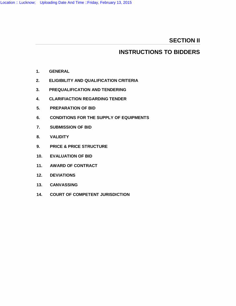
SECTION II
INSTRUCTIONS TO BIDDERS
1. GENERAL
2. ELIGIBILITY AND QUALIFICATION CRITERIA
3. PREQUALIFICATION AND TENDERING
4. CLARIFIACTION REGARDING TENDER
5. PREPARATION OF BID
6. CONDITIONS FOR THE SUPPLY OF EQUIPMENTS
7. SUBMISSION OF BID
8. VALIDITY
9. PRICE & PRICE STRUCTURE
10. EVALUATION OF BID
11. AWARD OF CONTRACT
12. DEVIATIONS
13. CANVASSING
14. COURT OF COMPETENT JURISDICTION
Location :: Lucknow; Uploading Date And Time ::Friday, February 13, 2015

1. GENERAL
1.1 The Employer, Uttar Pradesh Power Transmission Corporation Ltd. (UPPTCL) intends to proceed with this tender for which this Invitation for Prequalification is issued.
1.2 The Employer intends to prequalify firms or joint ventures to tender for the work outlined in the Prequalification Detail.
1.3 Work completion period is outlined in the Prequalification Detail.
1.4 General information on the location and scope of the works to be covered by the tender is outlined in annexure-I. 2. ELIGIBILITY AND QUALIFICATION CRITERIA
2.1 Prequalification will be based on the applicant meeting the minimum pass/fail criteria regarding the applicant’s general and particular experience, personnel and equipment capabilities, and financial position, specified in the Prequalification Data, as demonstrated by the applicant’s responses in the forms attached to the Letter of Application and other requested documentation. Specific requirements for joint ventures are also set forth in minimum qualification.
2.2 When the applicant intends obtaining highly specialized inputs (essential for execution of the contract) from specialized subcontractors, application forms shall be completed for such subcontractors and their inputs.
2.3 Experience of subsidiary companies or holding companies of bidder shall not be considered as experience of the bidder.
3. PREQUALIFICATION AND TENDERING
3.1 The employer reserves the right to: a) amend the scope and value of contract to be tendered, in which event only
those prequalified applicants who meet the amended requirements will be invited to tender for the contract.
b) reject or accept any application without assigning any reason thereof; and c) cancel the prequalification process and reject all applicants.
The Employer shall neither be liable nor be under any obligation to inform the applicant of the grounds for such action.
3.2 Applicants will be advised in writing by fax or electronic mail, of the result of their application and of the names of the prequalified applicants, without giving any reason for the Employer’s decision.
3.3 Price part of only those firms and joint ventures that have been prequalified under this procedure will be opened. A firm may apply for prequalification either individually and as part of a joint venture.
However, a firm or a member of a joint venture may participate as a tenderer, either individually or as a partner in a joint venture.
Location :: Lucknow; Uploading Date And Time ::Friday, February 13, 2015

3.4 Joint ventures must comply with the following requirements: a) Any tender shall be signed so as to legally bind all joint venture partners,
jointly and severally, and any tender shall be submitted with a copy of the joint venture agreement mentioning details for joint and several liability with respect to the contract.
3.5 The previous experience of firms who have worked in a joint venture for some other project but have now participated on individual basis or in joint venture with some other partner will not be considered for Pre qualification purposes. Their previous experience of JV will be considered for Pre qualification in present tender, if and only if the bid is submitted by the same JV partners.
4. CLARIFIACTION REGARDING TENDER
4.1 Prospective applicants may request in writing clarification of the tender documents requirements and the criteria for qualification at any time up to five (5) days prior to the deadline set for the submission of applications. The written responses will be sent (by fax / post) to all prospective applicants that have received the prequalification documents.
All queries should be sent to the following fax / postal addresses:
Fax no. : 0522-2287872 Postal address:
Superintending Engineer, Electricity Substation Design Circle-II, UP Power Transmission Corporation Limited
13th Floor, Shakti Bhawan Extension, 14-Ashok Marg, Lucknow-226001, U.P.
4.2 All information requested for prequalification shall be provided in English. Information should be submitted in the formats specified in the application forms in these prequalification documents
4.3 The application for prequalification shall consist of the following: a) The letter of Application b) The forms and documentation specified in the Prequalification Data
c) Earnest money deposit as specified in Section I Clause 8(4)
d) Proof of deposit of non-refundable fee as specified in Section I Clause 8(3).
Location :: Lucknow; Uploading Date And Time ::Friday, February 13, 2015
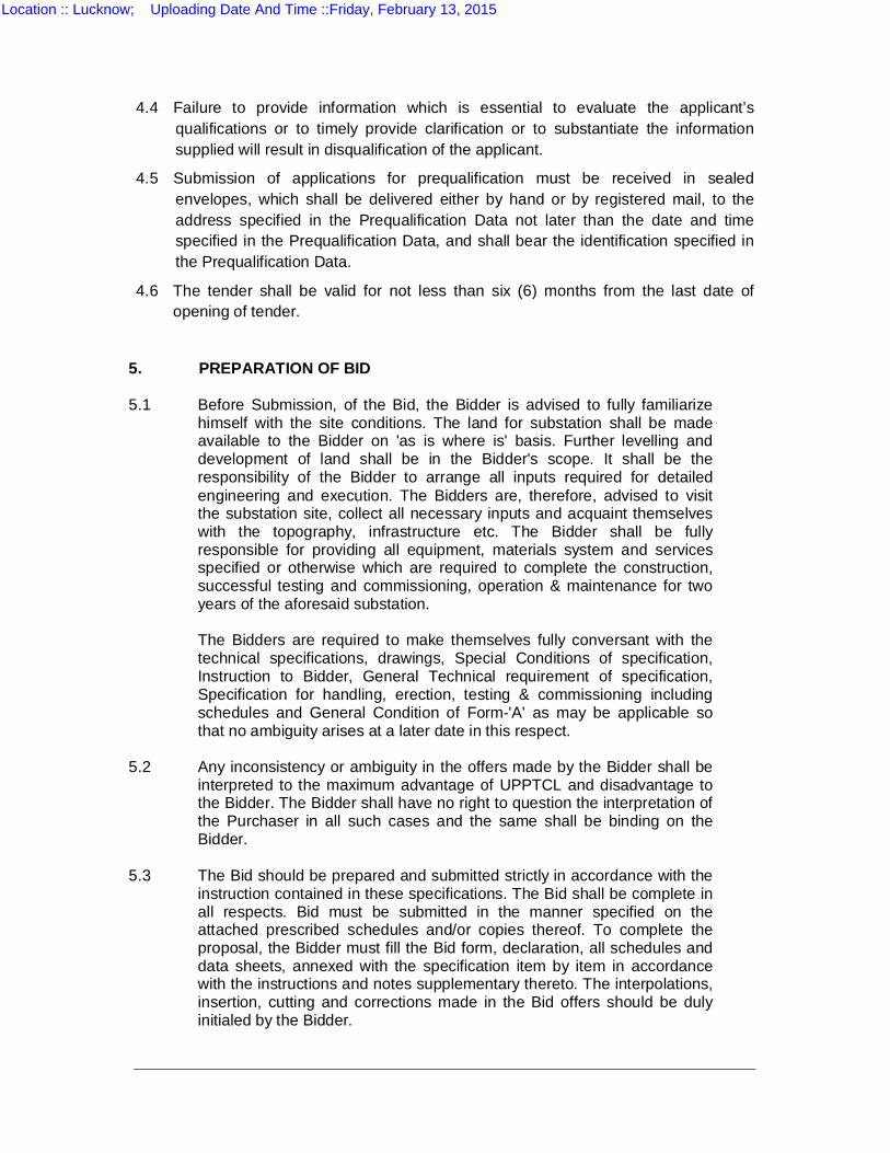
4.4 Failure to provide information which is essential to evaluate the applicant’s qualifications or to timely provide clarification or to substantiate the information supplied will result in disqualification of the applicant.
4.5 Submission of applications for prequalification must be received in sealed envelopes, which shall be delivered either by hand or by registered mail, to the address specified in the Prequalification Data not later than the date and time specified in the Prequalification Data, and shall bear the identification specified in the Prequalification Data.
4.6 The tender shall be valid for not less than six (6) months from the last date of opening of tender.
5. PREPARATION OF BID 5.1
Before Submission, of the Bid, the Bidder is advised to fully familiarize himself with the site conditions. The land for substation shall be made available to the Bidder on 'as is where is' basis. Further levelling and development of land shall be in the Bidder's scope. It shall be the responsibility of the Bidder to arrange all inputs required for detailed engineering and execution. The Bidders are, therefore, advised to visit the substation site, collect all necessary inputs and acquaint themselves with the topography, infrastructure etc. The Bidder shall be fully responsible for providing all equipment, materials system and services specified or otherwise which are required to complete the construction, successful testing and commissioning, operation & maintenance for two years of the aforesaid substation.
The Bidders are required to make themselves fully conversant with the technical specifications, drawings, Special Conditions of specification, Instruction to Bidder, General Technical requirement of specification, Specification for handling, erection, testing & commissioning including schedules and General Condition of Form-'A' as may be applicable so that no ambiguity arises at a later date in this respect.
5.2
Any inconsistency or ambiguity in the offers made by the Bidder shall be interpreted to the maximum advantage of UPPTCL and disadvantage to the Bidder. The Bidder shall have no right to question the interpretation of the Purchaser in all such cases and the same shall be binding on the Bidder.
5.3
The Bid should be prepared and submitted strictly in accordance with the instruction contained in these specifications. The Bid shall be complete in all respects. Bid must be submitted in the manner specified on the attached prescribed schedules and/or copies thereof. To complete the proposal, the Bidder must fill the Bid form, declaration, all schedules and data sheets, annexed with the specification item by item in accordance with the instructions and notes supplementary thereto. The interpolations, insertion, cutting and corrections made in the Bid offers should be duly initialed by the Bidder.
Location :: Lucknow; Uploading Date And Time ::Friday, February 13, 2015
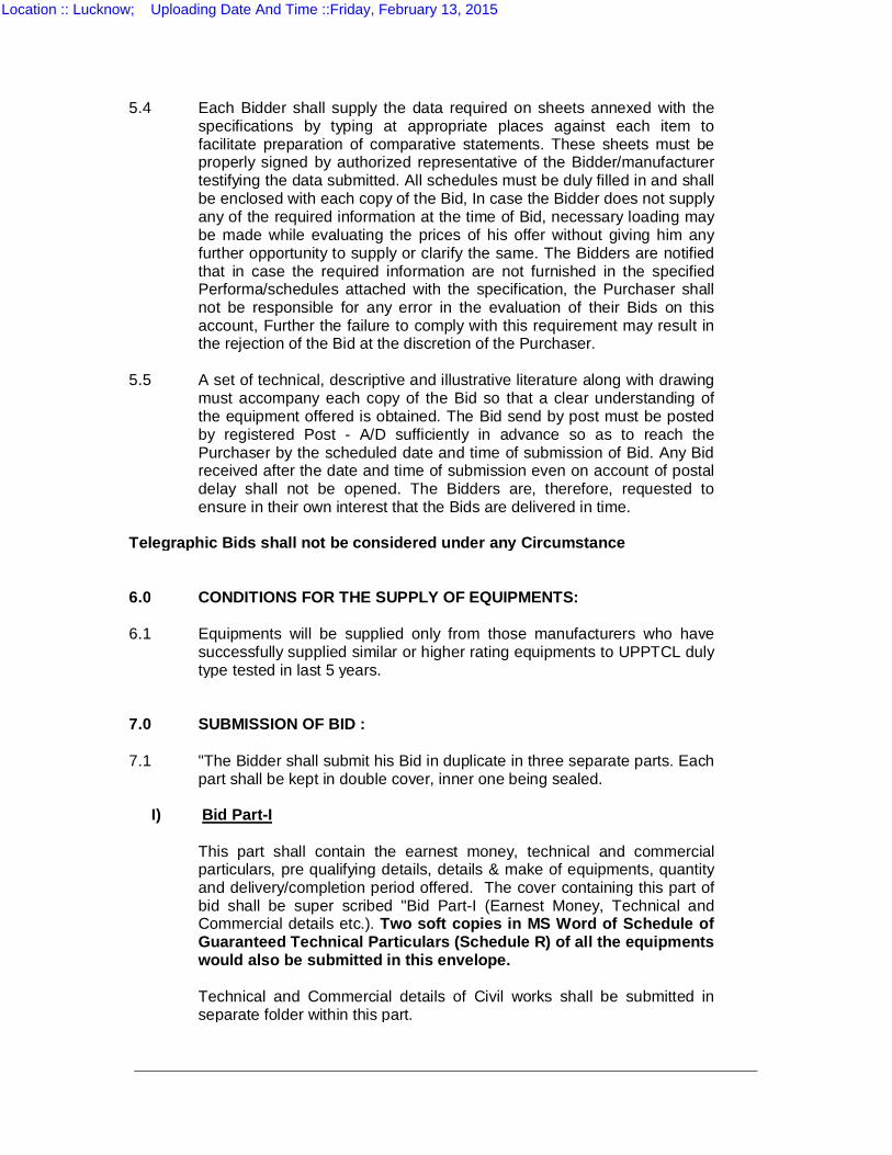
5.4
Each Bidder shall supply the data required on sheets annexed with the specifications by typing at appropriate places against each item to facilitate preparation of comparative statements. These sheets must be properly signed by authorized representative of the Bidder/manufacturer testifying the data submitted. All schedules must be duly filled in and shall be enclosed with each copy of the Bid, In case the Bidder does not supply any of the required information at the time of Bid, necessary loading may be made while evaluating the prices of his offer without giving him any further opportunity to supply or clarify the same. The Bidders are notified that in case the required information are not furnished in the specified Performa/schedules attached with the specification, the Purchaser shall not be responsible for any error in the evaluation of their Bids on this account, Further the failure to comply with this requirement may result in the rejection of the Bid at the discretion of the Purchaser.
5.5
A set of technical, descriptive and illustrative literature along with drawing must accompany each copy of the Bid so that a clear understanding of the equipment offered is obtained. The Bid send by post must be posted by registered Post - A/D sufficiently in advance so as to reach the Purchaser by the scheduled date and time of submission of Bid. Any Bid received after the date and time of submission even on account of postal delay shall not be opened. The Bidders are, therefore, requested to ensure in their own interest that the Bids are delivered in time.
Telegraphic Bids shall not be considered under any Circumstance 6.0 CONDITIONS FOR THE SUPPLY OF EQUIPMENTS: 6.1 Equipments will be supplied only from those manufacturers who have
successfully supplied similar or higher rating equipments to UPPTCL duly type tested in last 5 years.
7.0 SUBMISSION OF BID : 7.1 "The Bidder shall submit his Bid in duplicate in three separate parts. Each
part shall be kept in double cover, inner one being sealed.
I) Bid Part-I
This part shall contain the earnest money, technical and commercial particulars, pre qualifying details, details & make of equipments, quantity and delivery/completion period offered. The cover containing this part of bid shall be super scribed "Bid Part-I (Earnest Money, Technical and Commercial details etc.). Two soft copies in MS Word of Schedule of Guaranteed Technical Particulars (Schedule R) of all the equipments would also be submitted in this envelope.
Technical and Commercial details of Civil works shall be submitted in
separate folder within this part.
Location :: Lucknow; Uploading Date And Time ::Friday, February 13, 2015
II) Bid Part-IIA This part shall contain the prices for Civil Works. The cover containing
this part shall be super scribed "Bid Part-II A (Prices for Civil works)". Two soft copies of Price Schedule prepared in MS Excel would also be submitted in this envelope.
III) Bid Part-IIB
This part shall contain the prices for Electrical/Mechanical works covering
all works other than civil works. The cover containing this part shall be super scribed "Bid Part-IIB (Prices for Electrical/Mechanical works covering all works other than civil works)." Two soft copies of Price Schedule prepared in MS Excel (Q1 to Q4) would also be submitted in this envelope.
The envelopes of above three parts shall be kept in another envelope
which shall also be sealed and super scribed on top as under :- "BID FOR CONSTRUCTION OF 01 NO. 132 KV SUBSTATION
KURSATO (VARANASI) ON TURNKEY BASIS AGAINST UPPTCL SPECIFICATION NO. ESD- 385 DUE FOR OPENING ON 02.03.2015”
7.2 BID PART-I (EARNEST MONEY, TECHNICAL, COMMERCIAL AND
EQUIPMENTS DETAILS ETC.) 7.2.1 Bidder is required to deposit earnest money Rs 25,00,000.00
(Rupees Twenty Five Lac only). The earnest money shall be accepted in the following form only.
Bank Guarantee from a scheduled Bank in India, executed on a non-
judicial stamp paper as per U.P. Stamp Act, on the specified proforma appended with form ‘A’ in favour of “S.E., E.S.D.C.-II, Uttar Pradesh Power Transmission Corporation Ltd.” 13th Floor Shakti Bhawan Extn., Lucknow.
Any deviation from or addition to the text of the specified proforma of
Bank Guarantee shall render the bank guarantee invalid for the purpose of opening of Bid bid part-II.
7.2.2 Offers without earnest money shall not be considered under any
circumstances. 7.2.3 Besides the Earnest money, other relevant information and the following
documents, duly filled in must also accompany the Bid part-I.
Location :: Lucknow; Uploading Date And Time ::Friday, February 13, 2015
Application Forms 0 to 10 enclosed at Appendix A Application Form (0) Letter of Application Application Form (1) General Information Application Form (2) General Experience Record Application Form (2A) Joint Venture Summary Application Form (3) Particular Experience Record Application Form (3A) Details of Contracts of Similar Nature and
Complexity – Substations Application Form (4) Summary Sheet : Current Contract
Commitments/Works in Progress Application Form (5) Personnel Capabilities Application Form (5A) Candidate Summary Application Form (6) Equipment / System Requirements Application Form (7) Financial Capabilities Application Form (8) Litigation History Application Form (9) Restriction and black listing History Application Form (10) Bank Guarantee format for Earnest Money Deposit
Bid Schedules A to R enclosed at Appendix B
1. Schedule A : Bid Form 2. Schedule B : Qualifying details in following schedules :
B-1 : Experience details of Equipments of manufacturers on whom the orders are placed by UPPTCL
B-2 : Experience details of Equipments of manufacturers on whom the orders have not been placed by UPPTCL
3. Schedule C : Declaration 4. Schedule D : Proforma for joint undertaking by the collaborator /
associates with Bidder 5. Schedule E : Schedule General Particulars
E-1 : For Bidder E-2 : For Manufacturers
6. Schedule F : Schedule of deviations from “Special Conditions of Specification”
7. Schedule G : Schedule of deviations from “Technical Specification”
8. Schedule H : Schedule of deviations from “Instructions to Bidders”
9.
Schedule I
:
Schedule of deviations from “General technical requirements of specifications”
10. Schedule J : Schedule of deviations from “General condition of Contract” form “A”.
11. Schedule K : Schedule of deviations from “Technical specifications for handling, erection, testing and commissioning”
Location :: Lucknow; Uploading Date And Time ::Friday, February 13, 2015
12. Schedule L : List of Recommended spare tools & tackles 13. Schedule
M : List of recommended test sets & testing instruments
14. Schedule N : List of recommended spare parts and their prices 15. Schedule O : List of drawings& literatures enclosed with the Bid 16. Schedule P : Schedule of Guaranteed completion/delivery period 17. Schedule Q : Schedule of offered quantities. 18. Schedule R : Schedule of Guaranteed technical Particulars
19.
Complete technical details, Make, specification, type test reports, 3 years performance reports and literature of the equipments offered.
7.3 BID PART-II A (PRICES for Civil Works) as per BOQ attached as
annexures
BID PART-II B (PRICES for Electrical/Mechanical Supply & Works)
Only the prices and the following documents duly filled in must accompany Bid bid part-II B.
1. Schedule F : Price incidence of Schedule of deviations from
“Special conditions of Specifications”. 2. Schedule G : The Price incidence of schedule of deviations from
“Technical Specifications.” 3. Schedule H : The Price incidence of schedule of deviations from
“Instructions to Bidders.” 4. Schedule I : The Price incidence of schedule of deviations from
“General Technical requirement of Specification.” 5. Schedule J : The Price incidence of schedule of deviations from
“General Condition of Contract form A”. 6. Schedule K : The price incidence of schedule of deviations from
Technical specifications for handling, erection, Testing and commissioning
7. Schedule L : The prices of Recommended special tools and tackles.
8. Schedule M : The prices of Recommended test sets and testing instruments.
9. Schedule N : The prices of Recommended spare parts for five 5 years.
10. Schedule Q : Schedule of Quantity and Prices. Q-1 & 3 : For Supply Q-2 & 4 : For handling, erection, testing & commissioning
7.3.1
On the date of Bid opening at scheduled time, part-I of the Bid shall be opened publicly in the presence of authorized representatives of the bidders. The date and time of opening of Bid part-II A & B shall be intimated separately, later on.
7.3.2
Any action on the part of the Bidders to revise the prices and/or change the structure of price(s) at his own instance after the opening of the Bid may result in rejection of the Bid and/or debarring the Bidder for participation in any other tender by the Corporation for one year in first instance.
Location :: Lucknow; Uploading Date And Time ::Friday, February 13, 2015
8.0 VALIDITY: The Bids shall be valid for a period of six (6) calendar months from the
date of opening of the Part I or any extended date of opening. Bid with lesser validity are liable to be rejected.
9.0 PRICE & PRICE STRUCTURE : 9.1
The equipment shall be installed at designated substation in U.P. hence the Bidder must quote F.O.R. Destination prices of all the items alongwith Ex-works prices for dispatch to said substation in U.P. The unit F.O.R. destination price shall comprise of the following components.
(a) Ex-work price (b) Packing and forwarding charges. (c) Freight (d) Transit insurance charges against all risks.
(e)
Insurance charges for storage after receipt of equipment at destination store/substation against all risks till its commissioning/handing-over (whichever is latter) and 45 days thereafter.
The Bidders must clearly specify these components individually besides the F.O.R. destination prices.
9.2 TAXES & DUTIES :
The prices quoted should be exclusive of all taxes, duties, octroi charges etc., which will be paid extra at actuals on production of relevant original vouchers. However the Bidder must indicate the rates of various taxes/duties leviable, as on the date of Bid opening, on various price components as given in price schedule. Form C/D will not be demanded through bank.
9.2.1 NATURE OF PRICES:
The prices of all the items including ex-works prices, packing and forwarding, freight, insurance, erection, testing, & commissioning etc. shall remain “firm” in all respects throughout the currency of the contract.
10.0 EVALUATION OF BID: 10.1 In comparing Bids and making awards, the Purchaser may consider such
factors as, compliance with specification, relative quality and adaptability of suppliers or services, experiences, record of integrity in dealing, ability to furnish repairs and maintenance service, the time of delivery, capability to perform, and available facilities such as adequate shops, equipment plant, technical organization etc.
10.2 In case prices of some items are given in lump-sum, where unit prices are
required, Purchaser reserves the right to evaluate unit price on the basis of the quoted lump-sump prices.
10.3 In case, where a Bidder does not quote F.O.R. destination price asked
for, their quoted unit prices shall be loaded by appropriate additional factors on Ex-work prices as below.
Location :: Lucknow; Uploading Date And Time ::Friday, February 13, 2015
a) Packing charges @ 0.75% b) Forwarding charges @ 0.25% c) Freight for 1st 500 Kms @ 2% d) Freight for every next 250 Km. or part thereof @ 0.5% thereof. (For this purpose distance shall be taken from equipments manufacturers’
works to destination substation and in case, the distance is less than 500 Km. loading shall be done for a minimum distance of 500 Km.)
(e) Transit Insurance @ 0.5%
f) Insurance for storage after receipt of equipment at destination station @ 0.5%
10.4 No payment prior to dispatch of materials shall be made by the
Corporation under any circumstances. Bidders are advised not to ask any such advance payment. Request for such advance payment will not be considered even if the Bidders are willing to pay interests charges thereon. Bidders asking for advance payment are liable to be rejected.
10.5 Any rebate/discount linked with quantity, terms of payments in any
conditions shall not be considered for the purpose of evaluation and comparison of such offers vis-a-vis others. However, the same may be availed while placing order with such successful Bidders.
10.6 If the Bidder fails to quote prices for any of the item (s) / component(s) as
asked for or confirm its supply free of cost, the highest prices as quoted by other Bidder for the same shall be added to arrive at F.O.R destination computed prices of such Bidder for comparison purpose only.
10.7 The prices shall be compared inclusive of excise duty, Sales Tax/ Trade
Tax any other taxes/duties. 10.8 Loading on any account as may be deemed necessary in the opinion of
the Purchaser to bring the various offers at par to each other for comparison purposes, may be done at the discretion of the Purchaser.
11.0 AWARD OF CONTRACT : 11.1 The Purchaser is not bound to accept the lowest Bid and may reject any
or all the Bidders, without assigning any reason. 11.2 The successful Bidder shall have to enter into a contract agreement with
the Purchaser as per General conditions of form A and other special conditions attached with the Bid specifications.
Location :: Lucknow; Uploading Date And Time ::Friday, February 13, 2015
12.0 DEVIATIONS :
The offer should be strictly in line with conditions, specification and other requirements maintained in this Bid specification document. No deviations are permitted except under special circumstances. Should the Bidder wish to depart from the conditions, provisions and specifications of Bid documents in any way he must draw specific attention to such departure (s). All such deviations shall specifically be filled up in the relevant deviation schedule. If deviations are not specifically recorded in this schedule and submitted along with the Bid document it will be presumed that there are no deviations and this interpretation will be binding upon the Bidder.
Purchaser is, however, not bound to accept all or any deviations as
mentioned in such schedule. Bidders are also advised not to enclose their own standard or printed conditions etc, as the same shall not be considered.
13.0 CANVASSING:
No Bidder shall canvass any Corporation's official of the Engineer, with respect to his own or other's Bid. Contravention of this condition will result in rejection of the Bid. This clause shall not be deemed to prevent the Bidder from supplying to the Engineer any further information/ clarification asked for, by the Engineer.
14.0 COURT OF COMPETENT JURISDICTION :
All disputes arising out of and touching or relating to the subject matter of agreement, shall subject to the jurisdiction of Local Courts of Lucknow and High Court of Judicature at Allahabad only.
Location :: Lucknow; Uploading Date And Time ::Friday, February 13, 2015

SECTION III SPECIAL CONDITIONS OF SPECIFICATIONS
INDEX
1.0 SCOPE
2.0 EXCLUSIONS
3.0 NATURE OF CONTRACTS
3.1 CIVIL/ELECTRICAL CONTRACTS
3.2 VETTING OF DOCUMENTS
3.3 AGGREGATE CONTRACT VALUE
3.4 QUANTITY VARIATION
3.5 LIQUIDATED DAMAGES FOR DELAYS IN SUPPLY / COMPLETION PERIOD
4.0 TERMS & CONDITIONS
5.0 TENTATIVE SCHEDULE OF QUANTITIES OF EQUIPMENT & MATERIALS (ELECTRICAL)
6.0 TECHNICAL SPECIFICATIONS
7.0 PRICES
8.0 TAXES & DUTIES
9.0 TERMS OF PAYMENT
10.0 DEVIATIONS
11.0 COMPLETION PERIOD
12.0 EXPENDITURE UNDER CONTRACT
13.0 PROJECT IMPLEMENTATION SCHEDULE
14.0 PROGRESS REPORTS
15.0 COORDINATION AND REVIEW MEETING
16.0 DESIGN AND DRAWINGS
17.0 APPROVAL OF DRAWINGS
18.0 NAME PLATE, MARKING OF PARTS, LABELS
19.0 INSTRUCTION MANUALS
20.0 DOCUMENTS AND ERECTION DRAWINGS
Location :: Lucknow; Uploading Date And Time ::Friday, February 13, 2015

21.0 FURNISHING OF AS BUILD DRAWINGS, LAYOUTS AND MANUALS
22.0 TESTING AND COMMISSIONING ACTIVITIES
23.0 MATERIAL QUALITY
24.0 INSPECTION AND TESTING
25.0 PACKING
26.0 DESPATCH OF EQUPMENT
27.0 SECURITY DEPOSIT BANK GUARANTEE
28.0 PERFORMANCE GUARANTEE
29.0 RESPONSIBILITY OF THE BIDDER FOR COMPLETENESS OF CONTRACT
30.0 PATENTS
31.0 INSURANCE
32.0 TRAINING OF ENGINEERS
33.0 SPARE PARTS
34.0 LOCAL CONDITIONS
35.0 CONSTRUCTION MACHINERY
36.0 RESPONSIBILITY OF ERECTION / WORKS
37.0 EXTRA WORK SHIFT
38.0 CARE OF FINISHED WORK
39.0 CLEANING UP OF WORK SITE
40.0 BIDDER'S EMPLOYEES AT SITE
41.0 REPLACEMENT OF DEFECTIVE PARTS / EQUIPMENTS / WORKS & RECTIFICATION OF DEFECTS
42.0 SURPLUS MATERIALS
43.0 RESPOSIBILITY OF CONTRACTOR DURING TWO YEARS MAINTENANCE
PERIOD
44.0 WITHHOLDING OF PAYMENTS
45.0 NOTICE TO BIDDER
46.0 47.0
JURISDICITON CRITICAL DEFAULT AND DEBARMENT
Location :: Lucknow; Uploading Date And Time ::Friday, February 13, 2015
SPECIAL CONDITIONS OF SPECIFICATIONS FOR CONSTRUCTION OF 132 KV SUBSATAION
ON TURNKEY BASIS 1.0 SCOPE 1.1
The scope of work covers all activities related to design, engineering, manufacture, testing at works, supply of all required equipments and materials with accessories and auxiliaries to site, storage at site, insurance, construction including all civil works, handling, erection, testing, commissioning, putting into successful operation as single source responsibility on turnkey basis the 132 KV Substations, particulars of which are specified in Section -1.
1.2
THE BIDDER’S SCOPE OF WORK SHALL INCLUDE BUT NOT BE LIMITED TO THE FOLLOWING;
(a) Design & engineering of all systems, subsystems, equipments, materials and services.
(b) Manufacturing,, assembly, inspection, testing, packing, forwarding, loading, unloading, transportation, transit insurance & supply of all required structures, equipments & materials at site including port & custom clearance if required
(c) Receipt, storage, insurance, preservation & conservation of all structures, equipments & materials at site.
(d) Fabrication & reassembly (if any), erection, testing & commissioning of individual equipments, sub systems /systems.
(e) Commissioning & putting into successful operation.
(f) Providing engineering data, drawings and O & M manuals for Purchasers’ reference & records
(g) Furnishing T&P and spares on FOR site basis. (h) Training to Purchaser’s personnel.
(i) All Civil works including leveling, developing & dressing of land, security wall with gate & guard room, chain link fencing, control room building, transformer plinth, main & auxiliary foundations, cable trenches with racks & covers, roads, drainage system, sump well & sump house, store shed, water supply, overhead tank, pipe line & pump house, deep tube well and other required works specified under detailed civil specifications hereinafter.
(j) Over all co-ordination with internal/ external agencies, obtaining approval of the electrical inspector and other concerned authorities in respect of works to be carried out under the contract.
2.0 EXCLUSIONS (a) Termination of incoming lines on the incoming gantry (b) Transmission lines / towers if any.
Location :: Lucknow; Uploading Date And Time ::Friday, February 13, 2015

3.0 NATURE OF CONTRACTS 3.1
The Contract for construction of above 132 KV Substation on single source responsibility, on turnkey basis shall be awarded in THREE parts.
The first contract shall be called ‘Supply of equipment and material Contract’ covering all supplies, other than civil works, required to complete total scope under these specifications. The second contract shall be called “”Handling, Erection, testing, commissioning and handing over” other than civil works. The third contract shall be called ‘Civil Contract’ covering all civil works under its scope.
The Bidder shall be fully responsible for the works to be executed under all the contracts and any breach under one contract shall be automatically deemed as a breach of other contract giving UPPTCL right to take appropriate action under any / all the contracts including right to recover damages from any/ all the contracts or terminate any / all the contracts.
Notwithstanding executing the separate contracts & breakup of contract prices the contracts shall all times be construed as a single source responsibility contract. Complete project management, overall co-ordination between civil & electrical works for timely commissioning of Substation shall be Bidder’s responsibility.
3.2 VETTING OF DOCUMENTS
The Bidder shall bear all the charges in respect of vetting and execution of contract documents
3.3 AGGREGATE CONTRACT VALUE
The sum of contract values of “Civil Contract” and “Electrical Contract “ shall be the aggregate contract value. The limits for quantity variation and penalties for delays shall be 10 % of the aggregate contract value as under:
3.4 QUANTITY VARIATION
The quantities of individual items/works under any or all the above contracts may vary to any extent, however the total value of such variations shall not exceed the 10% of the aggregate contract value.
Such variations in quantities / work, under any of the above contracts, upto 10 % of the concerned contract value shall be allowed by concerned Engineer of Contract(Agreement authority) under intimation to other Engineer of Contract(Authorized field officer by Engineer of contract). However if such variation is likely to exceed 10% of the contract value of any contract , the variation shall be allowed by concerned Engineer of Contract after taking prior concurrence of other Engineer of Contract in writing.
3.5
LIQUIDATED DAMAGES FOR DELAY IN COMPLETION
In case of delay in completion period/handing over of substation beyond agreed schedule, liquidated damages @ 0.5% per week subject to maximum of 10% of aggregate contract value shall be deducted from the Bidder’s bills.
Location :: Lucknow; Uploading Date And Time ::Friday, February 13, 2015
However liquidated damages, if any, shall be adjusted against balance amount of 20% and 10% available for electrical & civil works respectively, which are to be released after successful commissioning.
4.0 TERMS & CONDITIONS
The terms & conditions of the contract shall be governed by the “General conditions for Supply of Plant and Execution of Work FORM ‘A’, these ‘Special conditions of specifications’ and other sections of these Bid documents, except for specific modifications/ amendments duly incorporated in the contract. In case of any contradiction or inconsistencies between provisions of these ‘special conditions’ and other sections of the Bid documents, the provisions contained in these special conditions shall prevail.
5.0
TENTATIVE SCHEDULE OF QUANTITIES OF EQUIPMENT & MATERIALS (ELECTRICAL )
5.1 The estimated quantities of equipments & materials required for proposed works at the Substation shall be as specified in Schedule of Quantities & Prices Schedule-Q
5.2
The quantities especially for cables/optical fibre, main & auxiliary structures, earthing rods, flats for earthing, conductors, disc insulators, PG clamps, tension & suspension fittings etc are for evaluation purposes. The quantities of these and other items may vary during detailed engineering and execution; however payment shall be made on the basis of unit rates.
5.3
For the items given as ‘Lot’ or ‘Lump sum’ the total prices as mentioned in price schedule shall be paid irrespective of the quantities of these items utilized during actual execution. Further the total prices of these items shall also include any other item not specified/ covered therein but required for completion of works. If any quantity of any lot item falls short during execution of work, it shall be responsibility of Bidder to make good the same without any extra cost to UPPTCL.
5.4.
The work shall be awarded on turnkey basis, The scope shall also include all such items/ works which are not specifically mentioned in these specifications but are required for completion of above 132 KVSubstation, hence if Bidder considers that any item/ work is not specified / covered but is / are required for successful completion of work, the Bidder shall quote for such item/ work in the Schedule of quantities & prices either on lump sum basis or by mentioning estimated quantity & unit rate , otherwise it shall be deemed to have been included in the Bidder’s scope without any extra liability on Purchaser.
5.5
The erection charges shall include supply of all non–consumable & consumable items required for complete erection, testing & commissioning of the equipments & systems which may or may not have been specifically mentioned in Price schedules.
6.0 TECHNICAL SPECIFICATIONS 6.1
UPPTCL procures all the equipments & materials for Substations. Keeping into consideration the interchangeability and future extension of substation, all equipments and materials to be supplied shall conform to the UPPTCL’s current Bid specifications for similar equipments & materials.
Location :: Lucknow; Uploading Date And Time ::Friday, February 13, 2015
The technical specifications of major equipments and accessory items are being enclosed hereinafter. In case of remaining items also UPPTCL’s prevailing technical specifications shall be binding on the Bidder. All the equipments & materials shall be supplied as per specifications, technical particulars, drawings & makes approved by Purchaser without any price implication irrespective of the technical particulars & makes quoted in the Bid.
6.2
UPPTCL has standard design/ drawings for main & auxiliary structures which shall be provided to Bidder. The Bidder shall supply main & auxiliary structures conforming to these designs/drawings. The equipment mounting bases shall also match with these auxiliary structures.
6.3
The handling, storage, erection, testing & commissioning shall be done as per relevant standards, manufacturer’s instruction manuals & where such standards/ instructions are not available; these activities shall be carried out as per UPPTCL’s norms & practices for similar voltage level substations constructed by UPPTCL.
6.4
The Bidder may propose alternative specifications for equipments, structures, materials and erection procedures for Purchaser’s consideration/ approval. It shall be sole discretion of Purchaser to accept or reject such alternatives & Purchaser’s decision shall be binding on Bidder.
6.5 EQUIPMENT MAKES
The Bidder shall supply the equipments of his own make for which the Bidder is also the manufacturer provided such equipment/s meet the prequalifying conditions for individual equipments.
The bought-out items shall also meet the prequalifying conditions for individual equipments Apart from above those firms /suppliers who fulfill following conditions may be considered as approved vendor when applied for .
1. Should have supplied the required material to UPPTCL in last five years with satisfactory performance.
2. Should be approved vendor of PGCIL 3. Should be approved vendor of other state Transco/ should have
supplied material to other State Transco during last 5 years with satisfactory performance. The vendor approval shall be issued separately in each case.
7.0 PRICES
The Prices of all the items and services shall remain “firm” in all respects through out the currency of the contract.
The prices of spare parts shall remain firm and valid for a period of three years from the date of taking over of the substation by UPPTCL.
8.1
The prices of imported items, if any, shall be inclusive of all taxes, duties , license fees, import/ custom duties etc legally payable .Any such taxes , duties and levies shall be Bidder’s account & no separate claim on this account shall be entertained by UPPTCL.
8.2
No Excise duty & Sales / trade tax in any form shall be payable by UPPTCL on bought-out items which shall be dispatched by Bidder’s sub-suppliers directly to the project site on sale-in-transit basis. All taxes and duties shall be deemed to be included in ex-works prices.
Location :: Lucknow; Uploading Date And Time ::Friday, February 13, 2015
8.3 The ex-work’s prices of Bidder’s self manufactured items, supplied by Bidder directly from their own works pertaining to direct transaction between Bidder and UPPTCL shall be exclusive of Excise duty, Concessional Sales / trade tax & any other taxes, duties & levies which shall be paid extra at actuals as legally applicable at the time of supply.
The Bidder shall identify such direct transaction items, which are exclusive of taxes & duties etc in Price Schedule along with taxes, duties etc presently payable otherwise taxes & duties etc shall be deemed to be included in ex-works prices.
8.4
The requisite concessional sales tax declaration forms for all direct transaction items as well as for bought out items under sale-in transit as may be applicable under Central Sales Tax or State law shall be provided by UPPTCL on request of Bidder.
8.5
The Bidder shall include Service tax and surcharge / cess etc on it, as applicable in their quoted prices and UPPTCL shall not bear any additional liability on this account.
8.6
The Contract shall be a ‘Divisible Contract’ with single point responsibility, hence no works contract tax shall be payable and UPPTCL shall not bear any liability on this account.
8.7
UPPTCL shall not bear any liability towards Turnover tax, corporate tax, sales tax on works contract, income tax and any other such taxes & surcharge / cess on them, these shall be to Bidder’s account as applicable.
8.8
UPPTCL shall be entitled to deduct Income tax and other taxes at source in accordance with provisions of Income tax/ other taxation laws as applicable from time to time.
8.9 MODVAT
The Bidder shall quote the prices after taking into account due credit under MODVAT scheme as per relevant Government policies wherever applicable. The UPPTCL shall not bear any liability on this account.
9.0 TERMS OF PAYMENT 9.1
The terms of payment shall be as per Clause 25 of FORM ‘A’ subject to deductions applicable as per terms of the contract. Mobilisation Advance Five percent (5%) of the Ex-works price component of supply of Electrical Equipment/Materials (including Mandatory Spares) shall be paid as an interest bearing initial advance after signing the contract Agreement and on submission of (a) Advance Bank Guarantee of 110% amount of mobilization advance having validity up to three months after scheduled completion period with six month claim period thereafter. However in case of delay of completion of S/S the validity of this shall be extended by the period of such delay. (b) Submission of an unconditional Performance Bank Guarantee towards faithful performance of the contract at the rate 10% of contract value . (c) Submission of detailed Bar Chart and its approval by UPTTCL Note: This advance payment is an optional payment. The contractor has the option of taking the interest bearing initial advance or otherwise. In case, the contractor opts for this interest bearing initial advance, the same shall be paid to the contractor on fulfillment of above conditions and an interest will be charged at the rate of 10% per annum. Mobilization advance and interest shall be adjusted proportionately against progressive payments. In case, the contractor opts not to take interest bearing advance as above, it would be mandatory for him to submit the documents listed at Sl. No. (b) &(c) above within Twenty Eight (28) days of issuance of LOI.
Location :: Lucknow; Uploading Date And Time ::Friday, February 13, 2015
9.2
Payment
9.2.1
9.2.2 9.2.3
In case of supply- payment shall be made as detailed below:
(a) 70% payment of supplied equipment after completion of the foundation of equipment. (b) 10% payment after erection. of equipment (c) Balance 20% amount to be released after satisfactory commissioning of entire substation, 100% completion of all electrical and civil works, adjustment of liquidated damaged if any and issuance of taking over certificate. Note: I- Supply schedule of equipments is to be adhered strictly as detailed below:
i) Power Transformers-On completion of CT, PT/CVT, CB and Isolators erection. ii) Control Panel & SAS- After completion of control room and Kiosk
II) Payment of above major equipment shall be done as per above supply schedule only, even if inspection/ supply is made earlier
III) Mobilization advance alongwith interest shall be adjusted proportionately against progressive payments .
IV) The supply of all equipments and material shall be in accordance with approved bar chart .
Civil Work & Erection Work : i) 90% of running bill subject to one bill per month. ii) Balance 10% after testing & Commissioning. In case of any contradiction between clause 9.2 of “Special Conditions of Specifications” and clause 25 of Form-A regarding “Terms of Payment” conditions under clause 9.2 of “Special Conditions of Specification” shall prevail.
10.0 DEVIATIONS
Unless brought out clearly, the Bidder shall be deemed to conform strictly to the provisions of the Bid documents. All deviations from the specifications shall be clearly brought out in respective schedule of deviations. Any discrepancy between the specification and the catalogue of the Bid, if not clearly brought out in the schedule, will not be considered as a valid deviation.
11.0 COMPLETION PERIOD
The substation has to be erected, tested and commissioned within 12 (Twelve) months from the date of letter of intent or from the date of handing over of land whichever is later.
The progress shall be monitored as per approved project implementation schedule & PERT.
In case of individual equipment/material the date of receipt of goods at UPPTCL site shall be treated as the date of delivery. In case of part dispatches the delivery shall be deemed to have been effected when last component/part of the equipment/material of the serviceable lot/set has been delivered.
12.0 EXPENDITURE UNDER CONTRACT
The Bidder shall furnish a cash flow chart with in 30 days of issue of letter of intent indicating month wise financial liabilities of the Purchaser during the execution of the project which is fairly representative of the actuals for supply, erection, testing and commissioning, individually and collectively.
Location :: Lucknow; Uploading Date And Time ::Friday, February 13, 2015
13.0 PROJECT IMPLEMENTATION SCHEDULE 13.1
Within one month of issue of letter of intent the Bidder shall submit to the Purchaser design, manufacture, transport, delivery, erection and commissioning schedules for all equipment along with the detailed network for all phases of the work for the execution of the job and completion of the project. Such schedules shall be reviewed, up-dated ad submitted to the engineer, once every three (3) months thereafter by Bidder.
13.2
The Bidder shall furnish the following schedules of work/ [PERT charts/Bar charts] to match the specified commissioning schedule within one month of placement or order.
i) Master PERT Net Work giving major events and showing dependence of various major activities in the completion of the job.
ii) Equipment system wise/sub-system wise detailed PERT Net Works for each of the major activities in the master PERT network covering activities of design and engineering, manufacturing, shop testing/procurement of materials/components, Purchaser's inspection, transport, storage at site, erection, testing and commissioning.
iii) Detailed PERT Net Work for civil works of each of the system/sub-systems covering task for civil construction, supervision and finishing. These PERTS will have complete coordination with PERTS for various equipment system/sub-systems.
iv) Bar chart for completion of works for each system as specified in respective sections of each volume, for construction and erection, from start of work at site to completion of work by the Bidder, giving various phases of activities. Each bar chart shall also indicate:
a ) The monthly expenditure likely to be incurred. b) Manpower at site (by major categories) to indicate monthly
deployment of work force at site. c) Pre-commissioning tests and commissioning PERT Net Work for
various systems and sub-systems. 13.3 All PERT Charts, Bar charts and schedules of activities shall be fully
integrated and co-related with master Net Work and with each other. 13.4 Bidder shall submit a detailed list of all the drawings/documents/write-
ups/back up calculation/design memoranda/instruction manuals proposed to be released for the complete job, volume and section wise, giving titles and contents of each drawings and documents soon after the placement of order.
14.0 PROGRESS REPORTS 14.1 All the progress reports submitted shall be fully co-related with the
schedules/ PERT networks and shall bring out clearly the shortfalls and proposed measures to cover up the shortfalls. Monthly progress report (six copies) shall be submitted on the status of following activities as on the last day of each calendar month so as to reach UPPTCL by 10th of the succeeding month:
i) Procurement of equipment/material ii) Manufacturing iii) Testing and inspection iv) Dispatch of equipment/material v) Receipt of material at site vi) Site activities vii) Payment received.
The progress report shall be distributed as directed by the Engineer.
Location :: Lucknow; Uploading Date And Time ::Friday, February 13, 2015
14.2 Civil works/Erection, testing and commissioning. i) The Bidder shall submit at such times and in such forms as may be desired
by the Engineer, schedules showing the programme and order in which the Bidder proposes to carry out the work with dates and estimated completion time for various parts of the work, prior to starting the erection work. The Bidder shall also furnish the outline of organization that he will set up for completion of the work according to the approved Erection/ construction schedules when so directed by the Purchaser.
ii) During the progress of work the Bidder shall submit a fortnightly progress report with photographs where required and such other reports on the erection work construction and organization as the engineer may direct and will report deviation from approved programme with reasons thereof and proposed measures to cover up the shortfall. He shall also submit programme for the next month.
iii) If for any reason the work is held up, the Bidder shall bring it to the attention of the Engineer in writing without any delay.
15.0 COORDINATION AND REVIEW MEETING 15.1 The Bidder shall be called upon to attend design/or other coordination
meetings with the Engineer, during the period of contract. The Bidder shall attend such meetings as and when required and fully cooperate with such persons and agencies involved during these discussions.
16.0 DESIGN AND DRAWING 16.1 Immediately upon receipt of acceptance of letter of intent, the Purchaser
shall furnish land map of each S/S showing tentative electrical layout (conventional type substation) to the contractor. After site visit, the contractor has to prepare & submit following drawings ( in 3 hard copies as well as in soft copy) for Purchaser’s approval :- i) Final Single Line Diagram ii) Final Electrical layout drawing along with Sectional drawing
clearly indicating location of equipment , control room, offices, store, residences, roads, lawns etc.
iii) Foundation, earthmat and cable trenches drawing showing cable trenches location and cross sections etc along with calculation of earthmat design taking into account the provisions of gravels, after measuring values of earth resistivity of sites.
In case of difference of opinion in above drawings, the decision of the Purchaser shall be binding on the Contractor. Thereafter, if required, the revised drawings shall be issued by the Contractor. Copies of standard drawings of Main & Auxiliary structure will be provided
after finalization of foundation plan
16.2 EQUIPMENT/SYSTEM DRAWINGS The Bidder shall submit drawings / literatures of all the equipments/
materials in duplicate to Engineer of Contract for his review and approval within a month of issue / acceptance of letter of intent.
The drawings to be submitted are specified under technical specifications of respective equipments. These shall necessarily include General arrangement drawing, foundation details, schematic wiring
Location :: Lucknow; Uploading Date And Time ::Friday, February 13, 2015
diagram, terminal blocks drawing where ever applicable, whether specified under technical specifications of respective equipments or not.
The control and protection schematics , cable interconnection and termination drawings between different equipments shall be prepared by the Bidder and shall be submitted in duplicate to Engineer of contract for his approval at least three months prior to commencement of cable laying and termination work.
The Bidder shall submit Switchyard and Control room lighting layout clearly showing different circuits, position of junction boxes, fuses, MCBs, model number wattage and make of lighting fixtures , routes of cable laid in switchyard and diagram of wiring carried out in different building mentioning cable sizes. Separate lighting layouts shall be submitted for all other remaining areas of the substation incorporating above features. The above drawings shall be submitted in duplicate to Engineer of Contract for his approval at least three months prior to commencement of lighting works.
The equipments / materials shall be supplied and work shall be carried out as per approved drawings.
The Contactor shall furnish two sets of each of above approved drawing / literature to the Consignee and two sets to Engineer of Contract within 10 days of respective approval.. The Bidder shall furnish two sets of schematic wiring diagrams and terminal block drawings of each equipment along with two sets of cable schedules & cable interconnection drawings to concerned Testing & Commissioning division within 10 days of respective approval
The Bidder shall also furnish two sets of Erection, testing , commissioning and O&M manuals of each equipment / system to Consignee , one set to concerned Testing & Commissioning Division and one set to the Engineer of Contract.
16.3 SUBMISSION AND APPROVAL OF DRAWINGS/DOCUMENTS 16.3.1 The Bidder shall follow a well defined coding system for proper and quick
identification of all systems / sub-systems / equipments /assemblies / sub-assemblies / accessories/other plant material/spare parts/special tools and plants and drawings for the execution of the plant and later for its operation and maintenance.
Copies of coding documents defining the above shall be supplied along with drawings to understand the system.
16.3.2 All drawings submitted by the Bidder shall be in sufficient details to indicate the type, size arrangement, weight of each component, details for packing and shipment, the external connections, fixing arrangements, dimensions required for installation arrangement, dimensions required for installation and interconnections with other equipment and other information specifically, as called for in the drawing schedules. All the equipments tapping points etc. shall be numbered according to pre-determined scheme/ system which shall be subject to approval of Purchaser.
16.3.3 Each drawing shall be clearly marked with the name of the Purchaser, unit designation, UPPTCL's Contract No. and the name of the project. If standard catalogue pages are submitted the applicable items shall be indicated therein. All titles, noting, markings and writings on the drawings shall be in English. All the dimensions should be in metric units.
16.3.4 If any dimension figures on a drawing or a plan differs from those obtained by scaling the drawing or plan, the dimensions as mentioned in figures on the drawing or plan shall be taken as correct.
Location :: Lucknow; Uploading Date And Time ::Friday, February 13, 2015
16.4 Submission and distribution of drawings/ documents All the drawings which do not require approval shall be submitted along with
reproducible in required number and those requiring approval shall be initially submitted for comments/approval before submitting along with reproducible as per "Document Distribution Schedule".
17.0 APPROVAL OF DRAWINGS 17.1 The Purchaser shall return to the Bidder one set of drawings, plans and
technical data requiring approval after marking them with their comments/ corrections, if any, either (a) marked 'Approved' or (b) marked 'Approved subject to incorporation of comments" or (c) marked 'Not Approved' with comments requiring resubmission of drawings etc. in 14 days or (d) marked 'Approval not required', where drawing is for information only. In case of (a) no further revision of drawings will be required. In case of (b) Bidder can proceed with the work but will resubmit the drawings incorporating the corrections as per comments only within fourteen (14) days. In case of (c) Bidder can proceed with the work only after resubmitting the drawings within fourteen (14) days and getting approval under (a)or (b) categories above. In case of (d) the Bidder drawing is deemed to have been received only for information purpose.
17.2 The Purchaser shall have the right to ask the Bidder to make any change in the design/drawing which may be necessary to make equipment conform to the provisions and intent of the contract, without any extra cost to the Purchaser.
The drawings submitted shall be re-viewed by the Purchaser and shall be modified by the Bidder as required. The Bidder shall incorporate such modifications and/or corrections and submit the final drawings for approval/reference.
17.3 No deviation from the approved drawings shall be permitted without the written approval of the Engineer
17.4 The review of drawings/ data by the Purchaser will cover only general conformance of the data of the specifications and document, interfaces with the equipment provided under the specifications, external connections and the dimensions which might effect substation layout. This review by the Purchaser may not indicate thorough review of all dimensions, quantities and details of the equipment, wiring, materials, any devices or items indicated or the accuracy of the information submitted. This review and/ or approval by the Purchaser shall not be considered by the Bidder, as limiting any of his responsibilities specified under these specifications and documents.
Approval/ comments conveyed as above shall neither relieve the Bidder of his contractual obligations and his responsibilities for correctness of dimensions, material of construction, quantities, design details, assembly fits, performance particulars, guarantees and conformity of the supplies with the specifications, schemes, systems and statutory laws, nor does it limit the Purchasers right under the contract.
17.5 Should any minor revision be made after 'approval', at the time of erection/ commissioning the Bidder shall redistribute prints and reproducible, clearly certifying the changes incorporated in the drawing and marking it in a block. Every revision shall be marked by a revision number, date and subject, in a revision block provided in the drawing, clearly marking the changes incorporated.
Location :: Lucknow; Uploading Date And Time ::Friday, February 13, 2015
17.6 The Bidder shall be responsible for and shall pay for any alterations of the work due to any discrepancies, errors and omissions in the drawings or other particulars supplied by him, whether such drawings or particulars have been approved by Engineer or not..
No extension of delivery periods shall be granted on this account. 18.0 NAME PLATE, MARKING OF PARTS, LABELS 18.1 All equipment shall have metal name plates fixed in suitable position with full
particulars engraved legibly thereon, and not painted. 18.2 Each main and auxiliary item of plant is to have permanently attached to it,
in a conspicuous position, a rating plate of non corrosive material upon which is to be engraved identifying manufacturer's name, equipment type or serial number, rating together with details of the loading/operating conditions under which the item or plant in question has been designed to operate and such diagram plates as may be required by the Engineer.
18.3 Each item of plant is to be provided with a name plate or label designating the service of the particular equipment. These inscriptions are, to be approved by the Engineer or as detailed in the appropriate sections of the technical specifications.
18.4 Such name plates or labels are to be white non hygroscopic material with engraved block lettering or, alternatively, in the case of indoor equipments., of transparent plastic material with suitably colored lettering engraved on the back
18.5 Each equipment in switchyard will have a clear marking of the name of bay, identification number, name of equipment. Such plates are to be fixed on control boxes of respective equipment to facilitate identification during routine operation/maintenance. A name plate giving name of bay shall be fixed at suitable location for identification of each bay.
18.6 All such name plates, instruction plates, lubrication charts, etc. shall be bilingual with Hindi inscription first followed by English. Provisions shall be made to fit in name plates, lubrication/connection diagram plates etc. .
18.7 In order to facilitate identification, the parts of the equipment shall be suitably marked.
19.0 INSTRUCTION MANUALS 19.1 The Bidder shall submit to the Engineer 'Descriptive Manuals', i.e. system
design concept, detailed catalogues of equipment and typical equipment instructions for this project, for all major systems and equipment, covered under this contract along with dispatch of equipment. These initial copies of descriptive manuals shall be in sufficient details, bringing out detailed internal construction, characteristics, performance parameters, principles of operation, maintenance requirements, replacement and renewals needed, erection and overhauling procedure, testing and operation procedure etc. for various equipment.
19.2 The integrated instruction manuals, fully defining the interfaces between various systems and complete in all respects shall be submitted by the Bidder one month before scheduled date of commissioning. The instruction manuals shall contain full details of designation and drawings of all the equipment furnished, the erection procedure, testing procedure, operation and maintenance procedure of the equipment, single line diagrams, and schematics. After the commissioning and initial operation of the plant, modifications/ additions/changes, wherever required shall be incorporated in
Location :: Lucknow; Uploading Date And Time ::Friday, February 13, 2015
the instruction manuals and drawings shall be submitted by the Bidder to the Purchaser.
19.3
The manuals shall be specific to the equipment supplied and not of general nature
20.0 DOCUMENTS AND ERECTION DRAWINGS The Bidder shall submit within a reasonable time but at least four (4) weeks
before dispatch of equipment (as per distribution schedule) the following drawings/ documents and instruction manuals etc. to the consignee and the Engineer.
i) List of item-wise equipment as proposed to be dispatched by the
Bidder. ii) Erection drawings along with reproducible prints of each drawings. iii) Instruction books for proper handling/ checking of material on receipt
at site/storage, erection and assembly of all equipment and necessary instruction for checking and recording proper assembly of the plant.
iv) Instruction sheets for proper balancing, alignment, adjustment, checking and calibrations as may be necessary.
v) Descriptive literature and drawings to illustrate the working principals, methods of assembly and dismantling of plants and equipment.
vi) Testing/commissioning format for recording data during erection/testing/ commissioning and trial run. These formats/data sheets shall clearly indicate the results obtained during shop tests and permissible deviations.
21.0 FURNISHING OF AS BUILD DRAWINGS , LAYOUTS AND MANUALS Notwithstanding any drawing, layout ,manual submitted earlier, the Bidder
shall furnish four sets of following as build drawings ,layouts, manuals etc along with their reproducible to the Purchaser one month prior to the handing over of substation ;
(i) Single line diagram, Foundation Earth mat and Cable trenches layout,
Electrical layout, Sectional drawing, Control / Relay / Battery / Carrier room drawings showing positions of panels etc.
Cable schedules and diagrams of cable interconnections between different equipments clearly showing cable numbers, terminal numbers, ferrule numbers and the purpose.
(ii) Drawings of all equipments as detailed in technical specifications of respective equipments necessarily including schematic drawings and terminal block drawing where ever applicable whether mentioned in respective technical specifications or not.
(iii) Switchyard and Control room lighting layout clearly showing different circuits, position of junction boxes, fuses, MCBs, model number wattage and make of lighting fixture, routes of cable laid in switchyard and diagram of wiring carried out in different building mentioning cable sizes.
iv) Commissioning test results of all the equipments (v) Erection, testing, commissioning, operation and maintenance manuals
of all equipments/ systems and subsystems. (vi) Any other relevant drawing, layout or/and manual asked for by
Purchaser.
Location :: Lucknow; Uploading Date And Time ::Friday, February 13, 2015
In case Purchaser asks for any clarifications / explanation in respect of above drawings, layouts, manuals etc the Bidder shall promptly clarify/ explain the matter to full satisfaction of the Purchaser.
22.0 TESTING AND COMMISSIONING ACTIVITIES The Bidder shall keep concerned Transmission division and Testing &
Commissioning Division fully informed of testing and commissioning activities being undertaken by them.
The Bidder shall inform in writing to the Executive Engineers of respective Transmission Division and T&C Division of the scheduled weekly programme of carrying out testing and commissioning of various equipments/ systems/ subsystems. The programme of the next week must be informed at least four working days prior to commencement of that week.
The testing and commissioning must be carried out in presence of their representative unless allowed otherwise by them.
The copies of test results and commissioning report must be promptly furnished to the Transmission and T&C divisions.
23.0
MATERIAL QUALITY
23.1 All materials used in construction of the equipment/plants/works shall be new and shall comply with the standards and codes specified and shall be selected from the best available, considering strength, durability and engineering practices. It will not deteriorate or distort under the prevailing extremes of atmospheric conditions and under the extreme service parameters. Where material/ workmanship have not been specifically described in these specifications the Bidder shall specifically obtain approval of the Engineer. The proposal for obtaining the approval shall clearly bring out the merit and demerit.
23.2 The workmanship and design shall be in accordance with the best engineering practice and shall be such as have been proved to be suitable for the intended purpose and for giving satisfactory performance under the prevailing climatic conditions and proposed system of supply. Liberal factors of safety shall be used throughout the design and special consideration shall be given for part subject to alternative stresses or shocks under service/operating conditions.
23.3 All consumables, lubricants, grease, control fluids etc. required for erection, operation, testing & commissioning shall have Indian equivalents, which can also be mixed with original lubricants for make-up purpose.
23.4 RAW MATERIAL : The Bidder shall himself be responsible for timely arrangement/
procurement of all the raw materials required for the manufacture of all Bided items and shall furnish their test certificates to the Purchaser. However, depending on the policy of the Govt. of India, Corporation may issue essentiality certificates, for arrangement of such raw materials through CEA, DOE, DGTD or other, who may allot the same to the Bidder, at their discretion directly from any of the producers of such raw materials or other sources, but without any financial liability to the Corporation of affecting / linking the delivery of the equipment with the availability of raw material against such certificates or recommendations.
Location :: Lucknow; Uploading Date And Time ::Friday, February 13, 2015
23.5 QUALITY CONTROL, PROGRAMME To ensure that the equipment construction work and the services covered
under this job are in accordance with the specifications and conform to the high standard of workmanship, it is obligatory on the part of the Bidder to adopt a suitable quality control program. Such a program shall include suitable hold point for check, for major equipments during manufacture at supplier's work during erection at site, and during the construction stage such that material checks for attaining proper strength and dimensional checks for attaining close tolerances required for equipment installation can be obtained.
In order to attain the above objectives, the Bidder shall draw out a plan
listing all quality control checks in detail, including all hold points at which the quality checks shall be applied, also specifically mentioning those hold points where the Purchaser shall also participate in the quality check to assure him of the quality of the products supplied. Such a program shall be outlined by the Bidder for the acceptance by the Purchaser. The Bidder shall furnish detailed information regarding his quality control program and its strict implementation. Following information shall be included in the proposal along with others regarding quality control program.
I. The quality control organizations and the proposal of its implementation.
II. The system for controlling drawings and documents for correctness. III. The system of quality control for raw materials, process control, and
maintaining tolerances during manufacturing, assembly and fabrication.
IV. Quality control during purchase of components, sub- systems and assemblies.
V. Methods for ensuring selection of proper vendors/ sub-vendors. VI. Inspection of testing at shop after assembly. VII. Control of accuracy during calibration of measuring and testing
equipments . VIII. Preservation and quality control during the transit. IX. Procedure for inspection before erection and quality control during
erection. X. System for storage and delivery. Bidder shall be wholly responsible for the quality control and quality
assurance for the manufacture, supply, erection, testing and commissioning etc.
23.6
During inspection, destructive testing and non destructive test evaluation shall be done, wherever applicable, in presence of Purchaser's representative in accordance with established norms. Directions of Purchaser shall be rigorously followed.
24.0 INSPECTION AND TESTING 24.1 The Purchaser reserves the right to inspect any machinery and material to
ensure that approved Q.A.P. is being strictly implemented by the Bidder or his Sub Bidder / Supplier under this contract, and to reject any item found defective in workmanship or design, or otherwise unsuitable for the use and purpose intended or which is not in accordance with the intent of this contract. The Bidder should, on demand by the Purchaser, rectify or replace
Location :: Lucknow; Uploading Date And Time ::Friday, February 13, 2015
such defective or unsuitable equipment, or the Purchaser may, at the Bidder's expense, rectify or replace such defective or unsuitable equipment, whether before or after supply
24.2
That Bidder shall, for purpose of clause 15 of the annexed conditions of contract Form-A inform to the Purchaser places of manufacture, testing and inspection of various equipment offered by him. Unless specifically provided otherwise, all tests shall be carried out at the Bidder's work or for brought out items at sub-vendors works, before dispatch.
24.3 The Bidder shall advise the Purchaser at least 4 weeks in advance as to when the equipment will be ready for stage/ final inspection at the Bidder's work or at his Sub-Bidder’s works
24.3.1
PENAL CHARGES
In case the equipment is not available for inspection at the time of arrival of inspection officers, the Bidder shall pay to UPPTCL towards futile journey a sum decided by Chief Engineer (Projects), UPPTCL and demanded by "Engineer of Contract". This amount shall be paid within 10 days form the date of demand, Further action for inspection of the material shall be taken only after the said amount is deposited
24.4 During inspection the Purchaser's Inspecting Engineers at all time have
access to all part of shops where the equipment is being manufactured and also shall be provided with all reasonable inspection facilities by the Bidder and / or sub-Bidders.
Even without scheduled inspection, the Engineer and/or his duly authorized representative shall have at all reasonable times access to the Bidder's premises , works or site and shall have the power to inspect and examine the materials and workmanship of the works during it’s manufacture or erection.
24.5
All plants equipment/ parts, sub assemblies/ assemblies shall comply with the requirement of type tests and shall be subjected to the routine/ acceptance tests specified in the set of standards adopted and to such other tests as are stipulated in the respective technical specifications.
The Purchaser reserves to himself the right of having at his own expense any inspection or special test of a reasonable nature at Bidder's premises or at site, in addition to those prescribed in applicable standards and the enclosed technical specifications.
24.6
The Engineer shall either depute his representative to witness the tests as applicable and inspect the material or shall waive the inspection. In case of waiver the Bidder or his sub-Bidder shall carryout the all applicable tests in absence of Purchaser’s representative. In both the cases i.e. either inspection or waiver the test certificates shall be submitted to Engineer of contract for approval and issue of dispatch authorization In case of inspection the test certificates must bear signatures of the Purchaser’s inspecting officer..
The Engineer of contract, within 10 days of receipt of test certificates, shall issue .approval/ dispatch authorization if test certificates are found satisfactory
In case test certificates are not found satisfactory the Engineer of contract , within 10 days of receipt of test certificates, shall communicate his objections and actions required to be taken in writing to the Bidder. The Bidder shall take remedial action and shall re-submit the test certificates or
Location :: Lucknow; Uploading Date And Time ::Friday, February 13, 2015
re-offer the material for inspection as asked for by the Engineer. Subsequent actions shall follow as in case of fresh offer for inspection. No extension of delivery / completion period shall be granted on this account.
24.7 REJECTON : Purchaser reserves the right to reject any equipment if during the tests at
works or site, the test value achieved do not comply with the respective standard/ specifications and exceeds that tolerable limits. Rejection of any equipment will not be held as a valid reason for delay in timely completion of the work
24.8
No equipment, to be furnished or used in connection with this contract shall be dispatched, until factory inspection and acceptance test have been carried out satisfactorily and dispatch authorization issued by Engineer of Contract. Such factory inspection of the equipment or approval of acceptance tests shall not however, relieve the Bidder from full responsibility for supplying equipment conforming to the requirements of this contract, nor prejudice any claim, right or privilege which the Purchaser may have because of the use of defective or unsatisfactory equipment should Purchaser waive the right to inspect any equipment, such waiver shall not relieve the Bidder any way from his obligations under this contract. The inspection/waiver by Engineer and/ or approval of test certificates shall in no way limit the liabilities and responsibilities of the Bidder in respect of the agreed quality assurance program, and the desired performance of the equipment.
24.9
In all cases where the contract provides for tests whether at the premises or works of the Bidder or of any Sub-Bidder, the Bidder shall provide free of charge such items as labour, materials, electricity, fuel, water, stores, apparatus and instruments as may be reasonably required to carry out effectively, such tests on the equipment in accordance with the contract and shall give facilities to the Engineer or to his authorized representative to accomplish inspection.
All the expenses incurred for testing including material consumed in testing shall be to the Bidder's account
24.10
Purchaser will not entertain any request for waiver of inspection on the ground that sub-vendors are not agreeing for the Purchaser's inspection. It is the responsibility of the Bidder to ensure that all the requirements of the Purchaser as envisaged in the technical specifications are incorporated.
24.11 The Bidder is required to record the following certificates on the invoices and challans of each and every consignment:
"Certified that material being dispatched against the above invoices
and challan has been inspected and tested by the representative of Engineer of the contract on (date) and all the test results were satisfactory, as per approved test certificate enclosed."
Or Certified that inspection of material being dispatched against the
above invoice and challan has been waived off by Engineer of Contract vide letter No......................Dt......................... (Copy enclosed) and all the acceptance and routine tests as per relevant standards and those provided in Contract, have been conducted and all the test results were found satisfactory as per test certificates enclosed."
Location :: Lucknow; Uploading Date And Time ::Friday, February 13, 2015
25.0 PACKING 25.1
All equipment shall be suitably protected, coated, covered or boxed and crated to prevent damage or deterioration during transit, handling and storage at site till the time of erection. While packing all the materials, the limitations from the point of view of availability of transportation facilities s in India should be taken into account. The Bidder shall be responsible for any loss or damage during transportation, handling and storage.
25.2
The Bidder shall include and provide for security protection and packing the plant so as to avoid loss or damage during transport by any mode.
25.3
All packing shall allow for easy removal and checking at site. Wherever necessary, proper arrangement for attaching slings for lifting shall be provided. All packages shall be clearly marked for with signs showing 'up' and 'down' side of boxes, and handling and unpacking instructions as considered necessary. Special precautions shall be taken to prevent rusting of steel and iron parts during transit and storage. Gas seals or other methods proposed to be adopted for protection against moisture during transit shall be to the satisfaction of the engineer.
25.4
The cases containing easily damageable material shall be very carefully packed and marked with appropriate caution symbols i.e. FRAGILE, HANDLE WITH CARE, USE NO HOOKS etc.
25.5
Each package delivered under the contract shall be marked by the Bidder at his expense and such marking must be distinct (all previous irrelevant marking being carefully obliterated). Such marking shall show the description and quantity of contents, the name of consignee and address, the gross and net weights of the package, the name of Bidder with a distinctive number of mark sufficient for purpose of identification. All markings shall be carried out with such materials as to ensure quickness of drying, fastness and legibility.
25.6
Each Package shall contain a note quoting specifically the name of the Bidder, the number and date of contract or order and the name of office placing the contract, nomenclature of the stores and include a schedule of parts for each complete equipment giving the parts number with reference to the General Arrangement/ Assembly drawing and the quantity of each part, drawing number and tag numbers.
25.7
All equipment/material shall be suitably packed for transport, carriage at site and outdoor storage during transit. The Bidder shall be responsible for any damage to the equipment during transit. The contents of each package shall bear marking that can be readily identified from the package list and packing shall provide complete protection from moisture, termites and mechanical shocks etc.
25.8
Any material found short inside the packing cases shall be supplied by the Bidder without any extra cost.
25.9
Not withstanding anything stated in this clause the Bidder shall be entirely responsible for any loss, damage or depreciation to the stores.
26.0 DESPATCH OF EQUPMENT 26.1
Detailed dispatch instructions will be intimated to the Bidder. All materials shall be dispatched by road.
26.2
The Bidder shall intimate, at least thirty (30) days in advance to the consignee as well as the concerned Superintending Engineer at site, the probable date when the equipment will be ready for dispatch from the works. Notification of delivery or dispatch in regard to each and every consignment
Location :: Lucknow; Uploading Date And Time ::Friday, February 13, 2015
shall be made to the Purchaser immediately after dispatch or delivery. The supplier shall further supply to the consignee a priced invoice and packing account of all stores delivered or dispatched by him. All packages, containers, bundles and loose materials forming parts of each and every consignment shall be described fully in the packing account, and full details of the contents of packages and quantity of material shall be given to enable the consignee to check the stores on arrival at destination.
26.3
A list in duplicate containing details of equipment for verification at site shall also be placed inside each package and shall correspond with the advice note. One additional copy of each of the package lists shall also be sent to the consignee
27.0 SECURITY DEPOSIT BANK GUARANTEE- Nil
28.0 PERFORMANCE GUARANTEE
1) The guarantee period of all the equipments (except Transformer) shall be 12 months from the date of taking over of plant as specified in Form ‘A’. For Transformer the guarantee period shall be 60 months from the date of taking over of the plant. The date of taking over shall be the date of commissioning of s/s suitable for commercial use or 100% completion of electrical and civil works whichever is later.
Damages for not meeting above performance guarantee shall be assessed and recovered from the Bidder at predetermined rates to be communicated by Engineer of Contract.
2) Successful bidder shall have to submit a Bank Guarantee for 10% of value of the contract within days twenty eight (28) days of issuance of LOI, which should remain valid till one year after commissioning of the s/s or completion of s/s in all respect whichever is earlier. Further before release of this bank guarantee, fresh bank guarantee equivalent to 10 % cost of power transformer shall have to be deposited which shall remain valid for further period of four years and claim period of six months thereafter.
29.0
RESPONSIBILITY OF THE BIDDER FOR COMPLETENESS OF CONTRACT :
29.1
The Bidder shall be entirely responsible for the execution of the contracts in all respect in accordance with the terms of the General Conditions of the contract Form A, Technical Specifications and Schedules attached hitherto.
29.2
The Purchaser shall have the right to require the Bidder to make any changes in the general arrangement which may be necessary in the opinion of the Engineer to make the equipment to conform to the provisions and the intent of the contract specification without additional cost to the Purchaser.
29.3
Inspection carried out by Engineer and approved by the Engineer of the Bidder's/Sub-Bidder's drawings or of the materials or of other parts of the works involved in the contract or of tests carried out either by the Bidder or by the representative of the Purchaser shall not relieve the Bidder of any part of the Bidder's obligations in meeting all the requirements of the technical specification or of the responsibility for the correctness of Bidder's drawing and documents.
Location :: Lucknow; Uploading Date And Time ::Friday, February 13, 2015
29.4
The equipment offered by the Bidder shall be complete in all respect with all mountings, fittings, fixtures and standard accessories, terminal connectors etc normally supplied with such equipments even though not specifically detailed in the specifications but essential for proper design, efficient operation and maintenance at no extra cost to the Purchaser unless specifically mentioned to be excluded in the list of excluded items of the contract. In the event of any controversy the decision of the Engineer of the contract shall be final and binding.
29.5
The scope of work under this Contract shall also include all such items which are not specifically mentioned in proposal/ contract but are necessary for completion of the substation, unless otherwise specifically excluded in this Contract.
30 PATENTS: The Bidder shall pay all royalties and license fees and shall have the
Purchaser harmless from loss or annoyance on account of over sight or claims of any kind, for violation or infringement of any letters of patent rights by the Bidder or any one directly or indirectly employed by him by reason of the use by him or them of any part, machine, manufacture and composition of material on the works in violation or infringement of such letters of rights.
31.0 INSURANCE :
31.1
The Bidder at his cost shall arrange, secure and maintain insurance as may be necessary and for all such amounts to protect his interests and interest of the Purchaser, against all risks during transit, storage at site and erection, testing and commissioning as detailed herein. The form and the limit of such insurance as defined herein together with the underwriter thereof in each case shall be as acceptable to the Purchaser. However, irrespective of such acceptance the responsibility to maintain adequate insurance coverage at all times during the period of contract shall be that of the Bidder’s alone. The Bidder's failure in this regard shall not relieve him of any of his contractual responsibilities and obligations.
31.2
The titles of equipment and material, supplied by Bidder or Sub-Bidder to UPPTCL, shall pass on to UPPTCL on ex-works dispatch basis. The transfer of title to UPPTCL shall not in any way relieve the Bidder of his responsibilities during the period of contract. Any loss or damage to the equipment during handling, transportation, storage and erection, testing and commissioning shall be to the account of the Bidder. The Bidder shall be responsible for preferring of all claims and making good for the damage or loss by way of repairs and/ or replacement of the portion of the works damaged or lost. The Bidder shall provide the Purchaser with a copy of all insurance policies and documents taken out by him in pursuance of the contract. Such copies of the documents shall be submitted to the Purchaser immediately after such insurance coverage is taken The Bidder shall also inform the Purchaser in writing at least sixty (60) days in advance, regarding the expiry, cancellation and/or change in any of such documents and insure revalidation/renewal etc. as may be necessary well in time.
31.3
The risks that are to be covered under the insurance shall include but not limited to, the loss or damage in transit, theft, pilferage, riot, civil commotion, weather conditions, accidents of all kinds, fire, war risk (during ocean transportation only) etc. The scope of such insurance shall cover the entire value of the works from time to time.
Location :: Lucknow; Uploading Date And Time ::Friday, February 13, 2015
31.4
All costs on account of insurance liabilities covered under the contract will be to Bidder's account and are deemed to be included in the contract price. However, the Purchaser may from time to time during the pendency of the contract, ask the Bidder in writing to limit the insurance coverage risks and in such case, the parties to the contract will agree for a mutual settlement, for reduction in contract price to the extent of reduced premium amounts.
31.5
Third Party Risk and Public Liability Insurance
The Bidder shall take necessary insurance to indemnify third party risk arising out of the work and its operation to be done by him at his own cost. The Bidder shall also take public liability and property damage liability insurance cover for the entire period of construction as well as operation & maintenance period as given below:
31.6
Public Liability and Property Damage Liability Insurance covering all operations under the contract.
a) Limit for bodily injury or death up to and including Rs.2,00,000/- for one person and Rs.5,00,000/- for each accident or incident.
b) Limits for property damage up to and including Rs.5,00,00,000/- (i.e. Rs. 5 Crores) for each accident or incident.
31.7 Automobile Liability Insurance On all self propelled vehicles used in connection with this contract, whether
owned, non-owned or hired by the Bidder, limits of insurance shall be as follows:
i) For public liability up to and including Rs.2,00,000/- for one person and Rs.5,00,000/- for each accident or incident.
ii) For property damage up to and including Rs.2,00,000/- for each accident or incident.
31.8 The insurance shall remain valid till 45 days after date of taking over of the Substation.
32.0 TRAINING OF ENGINEERS It shall be the responsibility of the Bidder to impart training to Purchaser's
engineer without any cost to the Purchaser i.e. free of cost for 50 man weeks inclusive of all equipment/systems; periods for various equipments to be mutually agreed between the Bidder and the Purchaser under this job. Suitable documentation, drawing and spare part details etc. shall be made available by the Bidder to the trainees so as to fully equip them for preventive maintenance, capital maintenance and overhaul of various equipments independently and with precision and speed. The Bidder shall submit a proposal for training covering a total of 50 man weeks inclusive of those specified elsewhere, covering recommended man weeks for design, operation, and maintenance of each type of major equipment/system, for the approval of Engineer before taking up the Training programme.
All expenditure on travel and stay for the trainees shall be borne by the
Purchaser. The Bidder shall make all suitable arrangements for stay of the trainees at their works/offices. It is important that during training free-exchange of know-how is provided so that the trainees are made fully conversant with the design, operation and maintenance of the plant/systems.
Location :: Lucknow; Uploading Date And Time ::Friday, February 13, 2015
33.0 SPARE PARTS 33.1 Bidder shall recommend a set of spare parts required for normal
maintenance of each equipment offered for a period of five years along with price of each spare part which shall remain valid for at least three years from the complication of guarantee period. The Bidder shall supply the spare parts promptly as and when required at reasonable prices through-out the useful life of the equipment.
33.2
The Bidder shall further guarantee that, if he goes out of production of spare parts then he will make available blue prints, manufacturer's drawings of spare parts and specifications of materials and any other details sufficient for manufacture of such spare parts at no cost to the Purchaser, to enable the Purchaser to fabricate or procure spare parts from other sources. Such fabrication or procurement of spares shall not constitute any infringement to the patent rights of the Bidder/ Sub-Bidder and shall not subject the Purchaser to payment of any royalty or other pecuniary benefits etc. The Bidder will adopt modern and efficient spare parts management system during the entire period since receipt of the spares at site.
34.0 LOCAL CONDITIONS 34.1
The Bidder is deemed to have informed himself of all local conditions and factors which may have any effect on the execution of the works covered under these documents and specifications. The Bidder is deemed to have familiarize himself with the Income Tax Act 1961, the Companies Act, 1956, Customs Act 1962, and other related acts and laws with latest revisions prevalent in India.
34.2
The Bidder shall obtain and pay for all permits and licenses or other privileges necessary to complete the work, certificate of which shall be delivered to the Engineer and will become the property of the Purchaser.
34.3
The laws, rules and regulations of all Government authorities in India, having jurisdiction over the work shall govern the work of this contract with the same force and effect as if incorporated in full into the Contract Documents. Where such laws, rules and regulations conflict with the contract documents the more-stringent requirements as interpreted by the Engineer shall govern. Should such conflict require changes in the contract documents, the Bidder shall promptly notify the Engineer.
35.0 CONSTRUCTION MACHINERY The Bidder shall bring his own construction/erection machinery for
construction, erection and commissioning of plant. 36.0 RESPONSIBILITY OF ERECTION/WORKS 36.1
The erection work shall be carried out under the supervision of the engineer or his authorized representative. The Bidder may obtain technical assistance from the specialists of the manufacture of plant and equipment for proper erection but the responsibility for quality of workmanship will rest with the Bidder.
36.2
The Bidder shall keep competent representative(s) constantly in charge of construction and erection work on the premises during working hours. He shall arrive at site at least two weeks in advance of start of work to acquaint himself of the local conditions and to set up his site office and erection organization. He shall obtain the approval of the Engineer wherever
Location :: Lucknow; Uploading Date And Time ::Friday, February 13, 2015
necessary, shall receive and comply with his direction, carry out work according to approved drawings, specification and supervise the work of all men employed by the Bidder or his Sub-Bidder. He shall inform the Engineer of any inconsistency or discrepancy that may appear in drawings, and specifications and will resolve it to the satisfaction of the Engineer.
36.3
The Bidder's representative at site shall not be withdrawn without the previous consent of the engineer in writing.
36.4
If in the opinion of the Engineer the progress of erection work by the Bidder at any stage needs expedition so as to ensure completion of work within the stipulated time, the engineer shall have the right to instruct the Bidder to increase the Bidder's manpower in appropriate categories and/or the working hour per day and/or erection equipment and the Bidder shall comply with these instructions forthwith.
37.0 EXTRA WORK SHIFT Night work shall be permitted with the written approval of the Engineer. The
Engineer may also direct such extra shift for the Bidder to ensure completion of contract on schedule if in his opinion such work is necessary.
38.0 CARE OF FINISHED WORK 38.1
The Bidder shall effectively protect the work from action of weather and from damage or defacement and shall cover finished parts wherever required for their thorough protection. Face work shall be perfectly clean and free from defects.
38.2
The Bidder and his Sub-Bidder(s) shall be responsible during the execution of their work for protection of the works which has been completed by others. Suitable means shall be used to protect finished work when moving equipment over it.
39.0 CLEANING UP OF WORK SITE 39.1
During erection, the Bidder shall without any additional payment, at all times keep the working and storage areas used by him free from accumulation of waste materials or rubbish. Upon completion of erection, he shall remove or dispose of in a satisfactory manner all temporary structures, waste and debris and leave the premises in a condition satisfactory to the Engineer.
39.2
All stripped wooden packing of the equipment shall become property of the Purchaser and they shall be delivered to the Purchaser as directed.
40.0 BIDDER'S EMPLOYEES AT SITE 40.1
The Bidder shall provide, at the proper time the necessary erectors, workmen, supervisors and other personnel duly qualified and experienced and in sufficient number for the erection, testing and commissioning and two years successful operation of the plant. The qualification and experience of different categories of personnel will require prior approval of the Purchaser.
40.2
The Bidder shall employ, at least one competent representative, whose name, qualification and experience shall have previously been communicated in writing to the Engineer by the Bidder for prior approval to supervise the erection of the plant and the carrying out of the works. The said representative or if more than one shall be employed, then one of such representatives shall be constantly present on site during working hours and any written orders or instructions which the engineer or his duly authorized representative whose name shall have been previously communicated in
Location :: Lucknow; Uploading Date And Time ::Friday, February 13, 2015
writing to the Bidder, shall be deemed to have been given to the Bidder. 40.3
The Engineer shall be at liberty to object to the representative or any person employed by the Bidder in the execution of the works, who shall misconduct himself or be incompetent or negligent and the Bidder shall remove the person so objected to, upon the receipt from the engineer, notice in writing requiring him to do so, and shall provide in his place a competent representative to be employed for the purpose of the work at site shall be made available when the Purchaser shall inform the Bidder in writing to that effect. The service of the Bidder's representative shall be made available for such period as the Engineer may require and he shall work at all reasonable times as may be necessary to complete the work within the period specified in the contract.
40.4
Bidder's representatives/employees shall abide by all general regulation, in force on the site and to any special conditions affecting the local administration, issued by the Purchaser or his duly authorized representative. All the employees of the Bidder living on the land belonging to the Purchaser shall be deemed to be aware of all dangers and risks incidental to the activities of the Purchaser and other Bidders and the conditions of the Purchaser's land and work from time to time, and the Purchaser will not be responsible for any injury arising therefrom. The Bidder shall discharge all the obligations under the Indian workman's compensation act and labor laws so far as it will affect the work under his control.
40.5 Employee identification The Bidder or his representative shall present his employee identification to
the Engineer. Suitable method of identification shall be developed by the Engineer/ Purchaser and the Bidder shall comply with the same.
41.0
REPLACEMENT OF DEFECTIVE PARTS/ EQUIPMENTS/WORKS & RECTIFICATION OF DEFECTS:
In case any defect is discovered during installation, testing and commissioning of equipment at site, the Bidder at his own cost shall rectify the defect/ replace the equipment or material promptly as to achieve the commissioning schedule.
In case any defect is discovered at site after taking over of the Substation by the Purchaser in the materials supplied or works done by Bidder, the Bidder at his own cost shall rectify the defect/ replace the equipment or material promptly as soon as informed by the Purchaser.
42.0 SURPLUS MATERIALS 42.1 On completion of work all the material left surplus from those supplied by the
Bidder under the contract for which payment has been claimed shall be handed over to the Purchaser at site stores in good condition. The Bidder shall give full details of the materials supplied by him , quantities utilized on works (based on the applicable drawings) and the balance returned to the Purchaser and shall obtain a clearance certificate within one month after completion and taking over of the Substation. The returning of material and rendering of accounts for the material is a precondition for release of payment against final bills and also the deposit towards performance at later date.
In the event of surplus material being lost, destroyed or damaged while being in Bidder’s custody before being taken over by the Purchaser, the
Location :: Lucknow; Uploading Date And Time ::Friday, February 13, 2015
Bidder shall be liable to make good the loss. In case the Bidder fails to return the balance surplus material, the cost shall be recovered from the Bidder’s pending bills, bank guarantees or by any other available means.
42.2 Any material handed over to the Bidder by Purchaser shall also be returned by the Bidder to the Purchaser at the time of handing over of the Substation. The provisions specified at above clause 42.1 shall also be applicable for such materials.
43.0. WITHHOLDING OF PAYMENTS The Purchaser may withhold the whole of or part of any payment due to the
Bidder, for reasons including but not limited to the following : i) Non furnishing of drawing, manuals, documents such as project
implementation schedule, progress reports, dispatch intimations, packing lists, erection, testing. commissioning intimations ,test reports etc
ii) Defective work not remedied or guarantees not met. iii) Claims filed against the Bidder iv) Failure by the Bidder to make due payments for the material or labor
employed by him. v) Damage to another Bidder directly employed by the Purchaser. vi) Insufficient progress. vii) Surplus material not returned. When the grounds for withholding payments are removed, payments of the
amounts due to the Bidder shall be made by the Purchaser. 44.0 NOTICE TO BIDDER 44.1 Any notice to Bidder as the Purchaser deems fit shall be served through
registered post at registered or present office/ mailing address incorporated in the contract.
44.2 All such postings shall be deemed good service of such notices and the time mentioned in the conditions for doing any act after the notice shall be reckoned from the date on which such notice shall reach to the Bidder in normal course.
45.0. JURISDICITON 46.0
All disputes arising out of and touching or relating to the subject matter of contract shall be subject to the jurisdiction of Local Courts at Lucknow under the High court of Judicature at Allahabad only. CRITICAL DEFAULT AND DEBARMENT
46.1 For construction of S/S or lines, contractor shall not be allowed to participate for a minimum period of 6 months or minimum one tender in case of delay from 6 moths to one year since strat of Critical Default. For delay of one year & upto two years, contractor shall not be allowed to participate in any tender for a period of one year (or minimum one tender).
46.2 For construction of transmission sub-station & lines, incentive @ 0.1% per month shall be made payable only if works as per agreement are completed before the stipulated completion period of the contract, No incentive will be applicable (@ 0.1%p.m.) if extension in construction period is allowed to contractor due to special circumstances of contract / Form A-
46.3 Critical Default & Incentive is not applicable for tenders invited only for supply of material;.
Location :: Lucknow; Uploading Date And Time ::Friday, February 13, 2015
ANNEXURE-1
PROFORMA OF GUARANTEE BOND FOR PERFORMANCE GUARANTEE (To be used by approved Scheduled Bank)
In consideration of the U.P. Power Transmission Corporation Limited, Lucknow (hereinafter called “the Corporation”) having agreed to exempt………………… ……………………. (herein after called the “The Contractors”) from the demand under the term and conditions of agreement dated……………………………………..made between………………………………….. and…………………………….for ………………………………. (herein after called ‘the said Agreement”) of security deposit for the due fulfillment by the said Contractor (s) on the terms and conditions contain in the said agreement, on production of a Bank Guarantee for Rs…………………………………….. Rupees…………………………..only). We ………………………………….……..Bank Ltd., ( hereinafter referred to as “the bank”) do hereby undertake to pay to the Corporation an amount not exceeding Rs…………………………………………..against any loss or damage caused to or suffered or would be caused to or suffered by the Corporation by reasons of any breach by the said Contractor (s) of any of the terms or conditions contained in the said Agreement.
2. We…………………………………..Bank Ltd., do hereby undertake to pay the amount due and payable under this guarantee without any demur, merely on a demand from the Corporation stating that the amount claimed is due by way of loss or damage caused to or would be caused to or suffered by the Corporation by reason of any breach by the said Contractor (s) of any of the terms or conditions contain in the said agreement or by reason of the Contractor (s) failure to perform the said agreement any such demand made on the bank shall be conclusive as regards the amount due and payable by the bank under this guarantee. However, our liability under this guarantee shall be restricted to an amount not exceeding Rs……………
3. We ………………………………….Bank Ltd., further agree that the guarantee herein contained shall remain in full force and effect during the period that would be taken for the performance of the said Agreement and that it shall continue to be enforceable till all the dues of the Corporation under or by virtue of the said Agreement have been fully paid and its claims satisfied or discharged or till the Corporation or their duly authorized officer certified that the terms and conditions of the said agreement have been fully and properly carried out by the Contractor (s) and accordingly discharges the guarantee. Unless a demand or claim under this grantee is made on us in writing on or before…………………………………………. We shall be discharged from all liability under this guarantee thereafter.
4. We………………………….Bank Ltd., further agree with the Corporation that the Corporation shall have the fullest liberty without our consent and without effecting in any manner our obligations hereunder to vary any of the terms and conditions of the said Agreement or to extend time of performance by the said Contractor (s) for time to time or to post pone for any time or from time to time any of the powers exercisable by the Corporation against the said Contractor (s) and to fore bear or enforce any of the terms and conditions relating to the s aid Agreement and we shall not be relieved from our liability by reason of any such variation, or extension, or extension being granted to the said Contractor (s) or for any forbearance, act or omission on the part of the Corporation or any indulgences by the Corporation to the said Contractor (s) or by any such matter or things whatsoever which under the law relating to sureties would but for this provision have effect of so relieving us.
5. We …………………………………Bank Ltd., lastly undertake not to revoke this guarantee during its currency except with the previous consent of the Corporation in writing.
6. Not withstanding anything contained above, the liability of the guarantor hereunder is restricted to the said sum of Rs. ……………………………………..and this guarantee shall expire on the…………………day of 20.. . Unless a claim under the guarantee is filed with the guarantor with six months of such date, all claim shall lapse and the guarantor shall be discharged from the guarantee. Dated…………day of………...20 For …………………Bank Ltd.,
Location :: Lucknow; Uploading Date And Time ::Friday, February 13, 2015
SECTION IV TECHNICAL SPECIFICATIONS FOR HANDLING, ERECTION, TESTING AND COMMISSIONING
INDEX
1.00 SCOPE
2.00 STANDARDS FOR ERECTION & COMMISSIONING
3.00 ERECTION OF MAIN GALVANISED STEEL STRUCTURES AND AUXILIARY STRUCTURES
4.00 STRINGING OF BUSBARS
5.00 ERECTION OF EQUIPMENTS
6.00 LAYING OF EARTH MAT & EARTHING OF EQUIPMENT WITH THE MAIN EARTH MAT
7.00 SPECIFIC REQUIREMENT FOR EARTHING SYSTEM
8.00 GENERAL NOTES ON EARTHING
9.00 CABLE LAYING & TERMINATIONS
10.00 ERECTION OF METERING SYSTEM & SCADA
11.00 ERECTION OF ASSOCIATED SYSTEMS
12.00 TESTING AND COMMISSIONING
Location :: Lucknow; Uploading Date And Time ::Friday, February 13, 2015
TECHNICAL SPECIFICATIONS FOR HANDLING, ERECTION, TESTING AND COMMISSIONING
1.00 SCOPE This specification covers the handling, storage of material at site, erection,
testing, commissioning, operation & handing over of all the equipment/sub systems/systems and complete sub-station as a whole on turn-key basis. The Bidder shall receive and store all the equipment at site on behalf of the Purchaser in storage yard/stores/sheds and transport the material to erection site and shall carryout erection, testing and commissioning of all equipment and accessory items as required. The Bidder shall be required to complete the work as per the completion schedule defined in the contract and the approved PERT chart.
1.01 In general the scope of work may be grouped as below : (a) Design & Engineering, Preparation of layouts / drawings / cable
schedules / inter connections etc.
(b) Unloading, handling & storage of all equipments & materials. (c) Erection of 132 & 33 KV equipments (i.e. transformers, breakers, and
their inter connection with conductors (Jumpering).
(d) Erection of 250 KVA station transformers & marshalling boxes, along with laying and terminations of power cables.
(e) Erection of auxiliary power supply system including AC Distribution Boards along with laying & terminations of power cables.
(f) Erection of 110 Volts batteries, battery charges and D.C. Distribution Boards.
(g) Erection of Energy Meters (h) Erection of illumination system including its cable laying &
terminations. (i) Erection of Air Conditioning and ventilation system
(j) Erection of Fire protection system. (k) Control Cable and power cable laying & terminations for complete
sub-station.
(l) Complete Civil Works as per civil works specifications. (m) Testing & commissioning of complete sub-station installation, putting
into Operation.
(n) Successful operation and maintenance for a period of two years and handing over to UPPTCL.
(o) Training to Purchaser’s personnel including operating staff.
Location :: Lucknow; Uploading Date And Time ::Friday, February 13, 2015
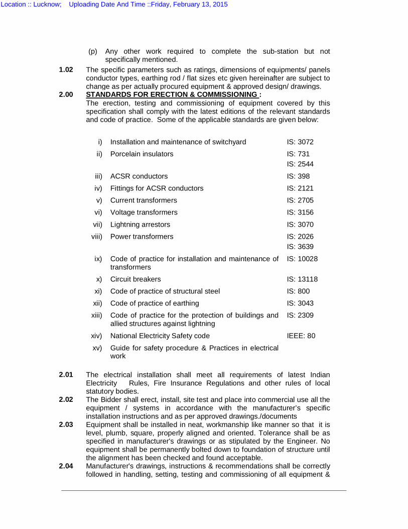
(p) Any other work required to complete the sub-station but not specifically mentioned.
1.02 The specific parameters such as ratings, dimensions of equipments/ panels conductor types, earthing rod / flat sizes etc given hereinafter are subject to change as per actually procured equipment & approved design/ drawings.
2.00 STANDARDS FOR ERECTION & COMMISSIONING : The erection, testing and commissioning of equipment covered by this
specification shall comply with the latest editions of the relevant standards and code of practice. Some of the applicable standards are given below:
i) Installation and maintenance of switchyard IS: 3072 ii) Porcelain insulators IS: 731
IS: 2544 iii) ACSR conductors IS: 398 iv) Fittings for ACSR conductors IS: 2121 v) Current transformers IS: 2705 vi) Voltage transformers IS: 3156 vii) Lightning arrestors IS: 3070 viii) Power transformers IS: 2026
IS: 3639 ix) Code of practice for installation and maintenance of
transformers IS: 10028
x) Circuit breakers IS: 13118 xi) Code of practice of structural steel IS: 800 xii) Code of practice of earthing IS: 3043 xiii) Code of practice for the protection of buildings and
allied structures against lightning IS: 2309
xiv) National Electricity Safety code IEEE: 80 xv) Guide for safety procedure & Practices in electrical
work
2.01 The electrical installation shall meet all requirements of latest Indian
Electricity Rules, Fire Insurance Regulations and other rules of local statutory bodies.
2.02
The Bidder shall erect, install, site test and place into commercial use all the equipment / systems in accordance with the manufacturer’s specific installation instructions and as per approved drawings./documents
2.03
Equipment shall be installed in neat, workmanship like manner so that it is level, plumb, square, properly aligned and oriented. Tolerance shall be as specified in manufacturer's drawings or as stipulated by the Engineer. No equipment shall be permanently bolted down to foundation of structure until the alignment has been checked and found acceptable.
2.04
Manufacturer's drawings, instructions & recommendations shall be correctly followed in handling, setting, testing and commissioning of all equipment &
Location :: Lucknow; Uploading Date And Time ::Friday, February 13, 2015
care shall be exercised in handling to avoid distortion to stationary structures, marring of finish, damaging of delicate instruments or other electrical parts etc. Adjustments shall be made as necessary to the stationary structures for the plumb & level, for the sake of appearance or to avoid twisting of frames or bending of hinged members.
Bidder shall engage manufacturer's Erection Engineers for major equipment to supervise the erection of the relevant equipment. Bidder shall erect & commission the equipment as per approved drawings and shall extend full co-operation to them. The Bidder shall be held responsible for any damage to the equipment consequent to not following manufacturer's instructions correctly
2.05 Where assemblies are supplied in more than one section, bidder shall make all necessary mechanical and electrical connections between sections including the connections between buses. Bidder shall also do necessary adjustments / alignments for proper operation of circuit breakers, isolators and their operating mechanisms All insulators & bushing shall be protected against damage during installation. Insulators or bushing chipped, cracked or damaged due to negligence or carelessness shall be replaced by the Bidder at his own expense well in time without affecting completion period.
2.06 Bidder shall take utmost care in handling instruments, relays & other delicate mechanisms. The blocking materials/mechanisms employed for the safe transit of the instruments & relays shall be removed after ensuring that the panels had been completely installed & no further movement of the same would be necessary
2.07 Inspection, storage, installation, testing & commissioning of transformer shall be in accordance with the Indian Standard code of practice. IS 1886 with latest edition and manufacturer’s instructions? All commissioning test as applicable, vide appendix C of IS: 1885 with latest edition shall be carried out.
Induction motors shall be installed & commissioned as per IS code of practice IS:900 with latest edition and manufacturer's instructions.
Care shall be taken during handling of insulating oil to prevent ingress of moisture or foreign matter in the testing, circulating, filtering or otherwise handling of oil. Rubber house shall not be used. Circulation & filtering of oil, heating of oil by regulated short circuit current during drying runs and sampling & testing of oil shall be in accordance with the manufacture's instructions & IS code of practice IS:1866 with latest edition.
2.08
Equipment furnished with finished coats of paint shall be touched up by the Bidder , if their surface has become dull or marred while handling.
2.09
The Bidder shall provide supervision, labour, tools, equipment, rigging materials and incidental materials, such as bolts, wedges, anchors, concrete, inserts etc. required to completely install, test and adjust the equipment
2.10
The Bidder shall provide and make all necessary arrangement for the safety of his staff and laborers at the site of works. The Purchaser will not be in any way responsible for any accident, minor or fatal to any person at the site of works or for any damages arising there from, during erection and this shall be the Bidder's responsibility. The staff insurance charges if any shall be borne by the Bidder. All labour rules shall be followed by the Bidder at his own cost.
Location :: Lucknow; Uploading Date And Time ::Friday, February 13, 2015
2.11 The Bidder shall provide and construct adequate storage shed for proper
storage of equipments, where sensitive equipments shall be stored indoors. All equipments during storage shall be protected against damage due to acts of nature or accidents. The storage instructions of the applicable standards, equipment manufacturer/ Purchaser shall be strictly adhered to.
2.12 The Bidder shall ensure that ; 2.12.1
Modern and best technologies are adopted and latest equipments are used to ensure least pollution during construction activities.
2.12.2
The equipments are properly stored, transported, handled and placed in position. to eliminate the chances of damages to the equipment.
2.12.3
All safety measures are taken for ensuring that no accidents occur during construction activities.
2.12.4
Best construction practices/norms are adopted to ensure safety, reliability and stability of substation structures.
2.12.5
Due care is taken to prevent erosion and drainage problems due to construction activities.
2.12.6 First aid kits are kept in order to tackle accidents. 2.12.7
No tree shall be cut until the Bidder has made necessary arrangement with the authorities concerned and permission is given to the Bidder to fell/cut such trees. The Bidder shall arrange to remove the obstacle as soon as possible with prior concurrence of the engineer.
2.12.8
Due care is taken to minimize the noise level (below 75 db) by construction equipment. Statutory provisions related to noise level shall be complied.
3.0
ERECTION OF MAIN GALVANISED STEEL STRUCTURES AND AUXILIARY STRUCTURES :
All structures shall be erected as per approved drawing. The Bidder shall carefully check the location and layout of anchor bolts embedded on foundations to ensure that structures can be properly erected. Any discrepancy in the anchor bolts/foundations shall be corrected before erection. Bidder shall carryout erection in the sequence agreed by the Engineer. The method of erection shall be modified whenever required by the Engineer.
After steel structure has been erected all burrs and abraded spots on bolt heads, and nuts, shall be spot painted with approved Zinc rich paint compound. Before paint is applied, the surface shall be dry and free from dust, dirt, scales and grease. No cutting, heating or enlarging of the holes shall be carried out without the prior approval of the Engineer.
4.00 STRINGING OF BUSBARS : 4.01
The Erection and Stringing of main, transfer, jack buses and connections with equipment terminal connectors and feeders shall be done as per the approved layouts/ drawings wherein the bus-sections, spans, jumpering arrangements, conductors etc shall also be specified.
Location :: Lucknow; Uploading Date And Time ::Friday, February 13, 2015
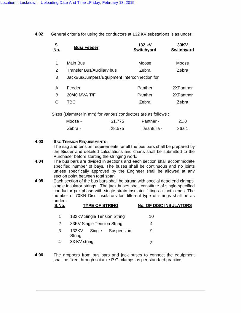
4.02 General criteria for using the conductors at 132 KV substations is as under:
S.
No. Bus/ Feeder 132 kV Switchyard
33KV Switchyard
1 Main Bus Moose Moose 2 Transfer Bus/Auxiliary bus Zebra Zebra 3 JackBus/Jumpers/Equipment Interconnection for
A Feeder Panther 2XPanther B 20/40 MVA T/F Panther 2XPanther C TBC Zebra Zebra
Sizes (Diameter in mm) for various conductors are as follows :
Moose - 31.775 Panther - 21.0 Zebra - 28.575 Tarantulla - 36.61
4.03 SAG TENSION REQUIREMENTS :
The sag and tension requirements for all the bus bars shall be prepared by the Bidder and detailed calculations and charts shall be submitted to the Purchaser before starting the stringing work.
4.04
The bus bars are divided in sections and each section shall accommodate specified number of bays. The buses shall be continuous and no joints unless specifically approved by the Engineer shall be allowed at any section point between total span.
4.05
Each section of the bus bars shall be strung with special dead end clamps, single insulator strings. The jack buses shall constitute of single specified conductor per phase with single strain insulator fittings at both ends. The number of 70KN Disc Insulators for different type of strings shall be as under :
S.No. TYPE OF STRING No. OF DISC INSULATORS 1 132KV Single Tension String 10 2 33KV Single Tension String 4 3
4
132KV Single Suspension String 33 KV string
9 3
4.06 The droppers from bus bars and jack buses to connect the equipment shall be fixed through suitable P.G. clamps as per standard practice.
Location :: Lucknow; Uploading Date And Time ::Friday, February 13, 2015
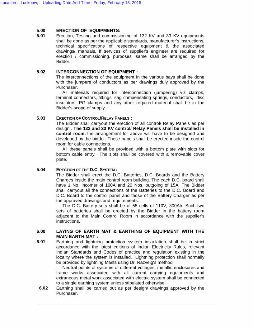
5.00 ERECTION OF EQUIPMENTS: 5.01 Erection, Testing and commissioning of 132 KV and 33 KV equipments
shall be done as per the applicable standards, manufacturer’s instructions, technical specifications of respective equipment & the associated drawings/ manuals. If services of supplier's engineer are required for erection / commissioning. purposes, same shall be arranged by the Bidder.
5.02 INTERCONNECTION OF EQUIPMENT : The interconnections of the equipment in the various bays shall be done
with the jumpers of conductors as per drawings duly approved by the Purchaser.
All materials required for interconnection (jumpering) viz clamps, terminal connectors, fittings, sag compensating springs, conductors, disc insulators, PG clamps and any other required material shall be in the Bidder’s scope of supply
5.03 ERECTION OF CONTROL/RELAY PANELS : The Bidder shall carryout the erection of all control/ Relay Panels as per
design . The 132 and 33 KV control/ Relay Panels shall be installed in control room.The arrangement for above will have to be designed and developed by the bidder. These panels shall be erected inside the control room for cable connections.
All these panels shall be provided with a bottom plate with slots for bottom cable entry. The slots shall be covered with a removable cover plate.
5.04 ERECTION OF THE D.C. SYSTEM : The Bidder shall erect the D.C. Batteries, D.C. Boards and the Battery
Charges inside the main control room building. The each D.C. board shall have 1 No. incomer of 100A and 20 Nos. outgoing of 15A. The Bidder shall carryout all the connections of the Batteries to the D.C. Board and D.C. Board to the control panel and those of the Battery Charger as per the approved drawings and requirements.
The D.C. Battery sets shall be of 55 cells of 110V, 300Ah. Such two sets of batteries shall be erected by the Bidder in the battery room adjacent to the Main Control Room in accordance with the supplier’s instructions.
6.00 LAYING OF EARTH MAT & EARTHING OF EQUIPMENT WITH THE
MAIN EARTH MAT : 6.01 Earthing and lightning protection system installation shall be in strict
accordance with the latest editions of Indian Electricity Rules, relevant Indian Standards and Codes of practice and regulation existing in the locality where the system is installed. Lightning protection shall normally be provided by lightning Masts using Dr. Razveig's method.
Neutral points of systems of different voltages, metallic enclosures and frame works associated with all current carrying equipments and extraneous metal work associated with electric system shall be connected to a single earthing system unless stipulated otherwise.
6.02 Earthing shall be carried out as per design/ drawings approved by the Purchaser.
Location :: Lucknow; Uploading Date And Time ::Friday, February 13, 2015
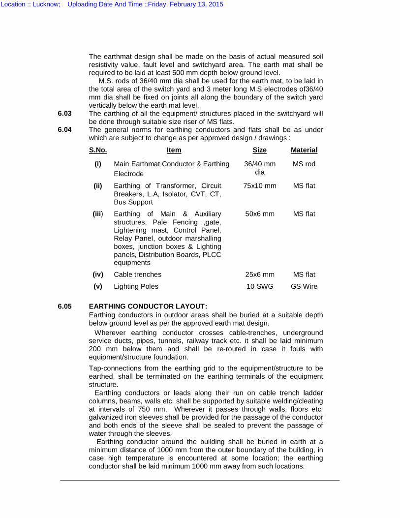
The earthmat design shall be made on the basis of actual measured soil
resistivity value, fault level and switchyard area. The earth mat shall be required to be laid at least 500 mm depth below ground level.
M.S. rods of 36/40 mm dia shall be used for the earth mat, to be laid in the total area of the switch yard and 3 meter long M.S electrodes of36/40 mm dia shall be fixed on joints all along the boundary of the switch yard vertically below the earth mat level.
6.03 The earthing of all the equipment/ structures placed in the switchyard will be done through suitable size riser of MS flats.
6.04 The general norms for earthing conductors and flats shall be as under which are subject to change as per approved design / drawings :
S.No. Item Size Material (i) Main Earthmat Conductor & Earthing
Electrode 36/40 mm
dia MS rod
(ii) Earthing of Transformer, Circuit Breakers, L.A, Isolator, CVT, CT, Bus Support
75x10 mm MS flat
(iii) Earthing of Main & Auxiliary structures, Pale Fencing ,gate, Lightening mast, Control Panel, Relay Panel, outdoor marshalling boxes, junction boxes & Lighting panels, Distribution Boards, PLCC equipments
50x6 mm MS flat
(iv) Cable trenches 25x6 mm MS flat (v) Lighting Poles 10 SWG GS Wire
6.05 EARTHING CONDUCTOR LAYOUT: Earthing conductors in outdoor areas shall be buried at a suitable depth
below ground level as per the approved earth mat design. Wherever earthing conductor crosses cable-trenches, underground
service ducts, pipes, tunnels, railway track etc. it shall be laid minimum 200 mm below them and shall be re-routed in case it fouls with equipment/structure foundation.
Tap-connections from the earthing grid to the equipment/structure to be earthed, shall be terminated on the earthing terminals of the equipment structure.
Earthing conductors or leads along their run on cable trench ladder columns, beams, walls etc. shall be supported by suitable welding/cleating at intervals of 750 mm. Wherever it passes through walls, floors etc. galvanized iron sleeves shall be provided for the passage of the conductor and both ends of the sleeve shall be sealed to prevent the passage of water through the sleeves.
Earthing conductor around the building shall be buried in earth at a minimum distance of 1000 mm from the outer boundary of the building, in case high temperature is encountered at some location; the earthing conductor shall be laid minimum 1000 mm away from such locations.
Location :: Lucknow; Uploading Date And Time ::Friday, February 13, 2015
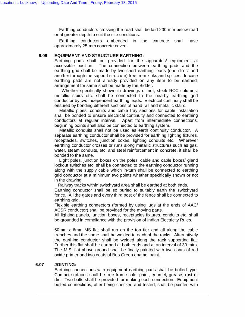
Earthing conductors crossing the road shall be laid 200 mm below road or at greater depth to suit the site conditions.
Earthing conductors embedded in the concrete shall have approximately 25 mm concrete cover.
6.06 EQUIPMENT AND STRUCTURE EARTHING: Earthing pads shall be provided for the apparatus/ equipment at
accessible position. The connection between earthing pads and the earthing grid shall be made by two short earthing leads (one direct and another through the support structure) free from kinks and splices. In case earthing pads are not already provided on any item to be earthed, arrangement for same shall be made by the Bidder.
Whether specifically shown in drawings or not, steel/ RCC columns, metallic stairs etc. shall be connected to the nearby earthing grid conductor by two independent earthing leads. Electrical continuity shall be ensured by bonding different sections of hand-rail and metallic stairs.
Metallic pipes, conduits and cable tray sections for cable installation shall be bonded to ensure electrical continuity and connected to earthing conductors at regular interval. Apart from intermediate connections, beginning points shall also be connected to earthing system.
Metallic conduits shall not be used as earth continuity conductor. A separate earthing conductor shall be provided for earthing lighting fixtures, receptacles, switches, junction boxes, lighting conduits etc. Wherever earthing conductor crosses or runs along metallic structures such as gas, water, steam conduits, etc. and steel reinforcement in concrete, it shall be bonded to the same.
Light poles, junction boxes on the poles, cable and cable boxes/ gland lockout switches etc. shall be connected to the earthing conductor running along with the supply cable which in-turn shall be connected to earthing grid conductor at a minimum two points whether specifically shown or not in the drawing.
Railway tracks within switchyard area shall be earthed at both ends. Earthing conductor shall be so buried to suitably earth the switchyard
fence. All the gates and every third post of the fence shall be connected to earthing grid.
Flexible earthing connectors (formed by using lugs at the ends of AAC/ ACSR conductor) shall be provided for the moving parts.
All lighting panels, junction boxes, receptacles fixtures, conduits etc. shall be grounded in compliance with the provision of Indian Electricity Rules.
50mm x 6mm MS flat shall run on the top tier and all along the cable
trenches and the same shall be welded to each of the racks. Alternatively the earthing conductor shall be welded along the rack supporting flat. Further this flat shall be earthed at both ends and at an interval of 30 mtrs. The M.S. flat above ground shall be finally painted with two coats of red oxide primer and two coats of Bus Green enamel paint.
6.07 JOINTING: Earthing connections with equipment earthing pads shall be bolted type.
Contact surfaces shall be free from scale, paint, enamel, grease, rust or dirt. Two bolts shall be provided for making each connection. Equipment bolted connections, after being checked and tested, shall be painted with
Location :: Lucknow; Uploading Date And Time ::Friday, February 13, 2015
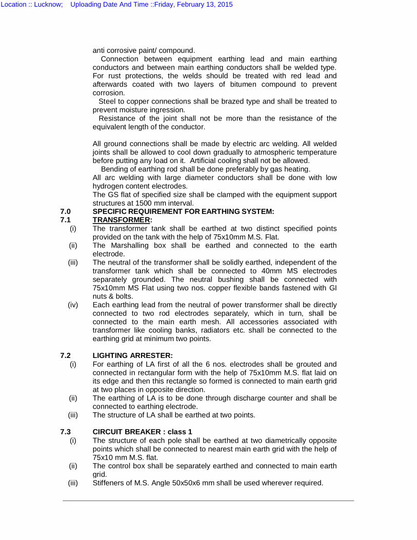
anti corrosive paint/ compound. Connection between equipment earthing lead and main earthing
conductors and between main earthing conductors shall be welded type. For rust protections, the welds should be treated with red lead and afterwards coated with two layers of bitumen compound to prevent corrosion.
Steel to copper connections shall be brazed type and shall be treated to prevent moisture ingression.
Resistance of the joint shall not be more than the resistance of the equivalent length of the conductor.
All ground connections shall be made by electric arc welding. All welded
joints shall be allowed to cool down gradually to atmospheric temperature before putting any load on it. Artificial cooling shall not be allowed.
Bending of earthing rod shall be done preferably by gas heating. All arc welding with large diameter conductors shall be done with low
hydrogen content electrodes. The GS flat of specified size shall be clamped with the equipment support
structures at 1500 mm interval. 7.0 SPECIFIC REQUIREMENT FOR EARTHING SYSTEM: 7.1 TRANSFORMER:
(i) The transformer tank shall be earthed at two distinct specified points provided on the tank with the help of 75x10mm M.S. Flat.
(ii) The Marshalling box shall be earthed and connected to the earth electrode.
(iii) The neutral of the transformer shall be solidly earthed, independent of the transformer tank which shall be connected to 40mm MS electrodes separately grounded. The neutral bushing shall be connected with 75x10mm MS Flat using two nos. copper flexible bands fastened with GI nuts & bolts.
(iv) Each earthing lead from the neutral of power transformer shall be directly connected to two rod electrodes separately, which in turn, shall be connected to the main earth mesh. All accessories associated with transformer like cooling banks, radiators etc. shall be connected to the earthing grid at minimum two points.
7.2 LIGHTING ARRESTER:
(i) For earthing of LA first of all the 6 nos. electrodes shall be grouted and connected in rectangular form with the help of 75x10mm M.S. flat laid on its edge and then this rectangle so formed is connected to main earth grid at two places in opposite direction.
(ii) The earthing of LA is to be done through discharge counter and shall be connected to earthing electrode.
(iii) The structure of LA shall be earthed at two points. 7.3 CIRCUIT BREAKER : class 1
(i) The structure of each pole shall be earthed at two diametrically opposite points which shall be connected to nearest main earth grid with the help of 75x10 mm M.S. flat.
(ii) The control box shall be separately earthed and connected to main earth grid.
(iii) Stiffeners of M.S. Angle 50x50x6 mm shall be used wherever required.
Location :: Lucknow; Uploading Date And Time ::Friday, February 13, 2015
7.4 ISOLATORS :
i) Each pole structure shall be earth at two places. (ii) Earth switch of Isolator shall be separately earthed with the help of
75x10mm M.S. flat and will be clamped with structure with the help of cleats provided at 750mm distance.
(iii) Isolator base to pie structure shall be connected with help of flexible bond. (iv) Control box for earthing switch shall also be earthed.
7.5 INSTRUMENT TRANSFORMER (CT/CVT/PT) :
i) The secondary windings of instrument transformers shall be earthed at one point preferably at control panel by 8 SWG galvanized steel wire.
(ii) The enclosing case and metal supporting frame work shall be earthed by 75x10mm M.S. Flat at two places.
(iii) Earthing terminal of each capacitor voltage transformer shall be directly connected to rod earth electrode, which in turn, shall be connected to station earthing grid.
7.6 POST INSULATOR :
(i) Metal base of each insulator stack and supporting structure steel shall be earthed using one 75x10mm M.S. Flat.
7.7 SWITCH YARD FENCE AND GATE :
(i) The two angle support of pale fencing gate shall be earthed with 50x6mm flat which will be connected to earthing electrode specially grouted for gate independent of main earth grid electrodes.
(ii) After that the two electrodes shall be connected with 50x6mm flat which in turn will be connected to main earth grid at two places in opposite direction.
(iii) The pale fencing and chain link fencing shall be earthed by 50x6mm flat at interval of 6m and connected to nearest main earth grid. This means that every alternate upright support shall be earthed.
7.8 EQUIPMENT STRUCTURE: These will be earthed by 75x10mm M.S. flat at two diametrically opposite
points and shall be connected to main earth grid near to it. 7.9. MAIN STRUCTURES WITHOUT LIGHTENING PROTECTION SHIELD
WIRE: (i) Any two diametrically opposite legs of each main structures with or without
peak in yard shall be earthed by 50x6mm M.S. flat connected at base of the support which in turn will be connected to main earth grid at two places in opposite direction.
7.10 MAIN STRUCTURES WITH PEAK: (i) Where peaks is provided on tower and earth wire from line tower inter
connecting tower is connected to peak, the earth wire must be connected to earth mat using the same conductor as per earth wire.
7.11 CABLE TRENCH :
(i) M.S. flat of 25x6mm shall continuously run on cable racks grouted in the trench. The flat shall be in contact with one wall after trench.
(ii) The top rack angle of trench shall be connected with the M.S. flat 25x6mm already running on the bottom rack angle by another 25x6mm flat at every
Location :: Lucknow; Uploading Date And Time ::Friday, February 13, 2015

750mm where the angles are grouted in the wall. (iii) The 25x6mm M.S. Flat running over the bottom rack shall be welded with
each and every angle piece of bottom rack. (iv) The above flat shall be connected to main earth grid at an interval of 30m
with 125x6mm flat. 7.12 LIGHTING POLE :
(i) Each street light pole grouted in yard shall be earthed with the help of 10 SWG. galvanized steel wires which will be bolted with the pole 300mm above ground level and the 2nd end shall be connected to main earth grid.
(ii) Junction Boxes on the poles, flood lighting supporting structures etc. shall also be earthed by 10 SWG galvanized steel wire which shall be run along with the supply cable and shall be connected to main earth grid at two points.
7.13 CABLES : (i) Metallic sheaths, screens or shields and armour of all multi core cable
shall be earthed at both end. (ii) Metallic sheaths and armour of single core cable shall be earthed only at
switch gear end and kept insulated at other end. 7.14 CONTROL, RELAY AND OTHER PANELS :
(i) All control and relay panels shall be connected first with one M.S. flat of 50x6mm at points marked in panels with the help of nuts & bolts and then the flat 50x6mm shall be connected with main earth grid all around control room building in two opposite direction.
(ii) Battery chargers and Distribution boards shall also be connected with 50x6mm MS Flat and which in turn shall be connected to main earth grid around control room in two opposite direction.
(iii) All other panels such as PLCC etc. shall also be earthed with 50x6mm M.S. flat and shall be connected to main earth grid
7.15 MISCELLANEOUS ITEMS: The various other items which are not covered under the various heads as
enumerated above shall also be covered under the scope of this work. Their earthing shall be done as directed by Engineer at site.
8.0 GENERAL NOTES ON EARTHING : 8.1 LAYING OF M.S. FLAT:
(i) The M.S. rod, MS flat and G.I. Wire shall be laid below the ground level in each area as per drawing.
(ii) MS Flat shall be laid inside ground on its edge as well as on flat depending upon situation.
(iii) Where ever the earthing conductor crosses the trench it shall be in the bottom of trench.
8.2 WELDING: (i) Surfaces to be welded shall be made absolutely free from grease, paint, oil
and scales etc. (ii) All welds shall be free from defects like blow holes, slug inclusion, lack of
penetration etc. welds shall show uniform sections and weld size need not exceed thickness of thinner part joined.
(iii) Welding electrode used shall be ISI mark only. (iv) Earthing strips if crossing each other or any other structure shall be
welded on that point.
Location :: Lucknow; Uploading Date And Time ::Friday, February 13, 2015
(v) The MS flat shall be wrapped around the 40 mm round M.S. bar of main earth grid and shall be welded on both sides and width of flat on top as shown in relevant drawing no.8/004.
(vi) M.S. Flat shall be lap jointed with over lapping being 150 mm. The welding shall be done along the length and breath in all direction.
8.3 HOLES: i) (Holes in the M.S. Flat shall be either punched or drilled. However drilled
holes shall be preferred. (ii) All burrs left after drilling or punching shall be removed completely. (iii) Holes adjacent to bends shall be drilled or punched after bending. (iv) Holes shall be invariably circular oval or lobbed forms of hle shall not be
permitted. (v) The size of the hole shall be according to bolt provided in various
equipments at the place of earthing. But in all cases the diameter of the hole shall be only 1.5mm more than the diameter of the bolt in place for earthing of equipment.
8.4 CUTTING & BENDING :
(i) The M.S. Flat shall be given bend of 900 over the foundation of structures while welding it with structure.
(ii) While bending the M.S. flat, it should be ensured that fracture of material does not take place.
(iii) Cold bending in case of smaller section such as 25x6 or 50x6mm and hot
bending in case of 75x10mm can be done. (iv) All cuttings of flat should be done either by punch or by hacksaw blade but
in no case there may be any burr on the edge end. It should be properly filed.
8.5 PAINTING : (i) To avoid rusting all the under ground welds should be cleaned properly
and painted with two coats or black bituminous paint. (ii) All earthing leads above ground level shall be painted with one coat of red
oxide primer and then with two coats of anti corrosive green paint. (iii) The G.I. structure at the place of welding shall be painted with zinc rich
oxide paint. (iv) The M.S. angle wherever used as stiffener shall also be painted with two
coats of anti corrosive paint.
8.6 OTHERS: The other technical works shall also be carried out as per UPPTCL
practice for 132 KV Substations and as directed by the Engineer. 9.0 CABLE LAYING & TERMINATIONS: 9.01 CABLE TAGS AND MARKERS:
(i) Each cable and conduit run shall be tagged with numbers that appear in the cable and conduit schedule.
(ii) The tag shall be of aluminum with the number punched on it and securely attached to the cable conduit by not less than two turns of 20 SWG GI wire conforming to IS:280 . Cable tags shall be of rectangular shape for power cable and of circular shape for control cables.
(iii) Location of cables laid directly underground shall be clearly indicated with cable marker made of galvanized iron plate.
Location :: Lucknow; Uploading Date And Time ::Friday, February 13, 2015
(iv) Location of underground cable joints shall be indicated with cable maker with an additional inscription “Cable joints”.
(v) The marker shall project 150mm above ground and shall be spaced at an interval of 30 meters and at every change in direction. They shall be located on both sides of road and drain crossings.
(vi) Cable tags shall be provided on all cables at each end (just before entering the equipment enclosure) on both sides of a wall or floor crossing, on each duct /conduit entry and at each end & turning point in cable tray/ trench runs. Cable tags shall be provided inside the switchgear, motor control centers, control and relay panels etc., wherever required for cable identification, where a number of cable enter together through a gland plate.
9.02 CABLE SUPPORTS & CABLE TRAY MOUNTING ARRANGEMENTS (i) The Bidder shall provide embedded steel inserts on concrete floors/ walls
to secure supports by welding to these inserts or available building steel structures.
(ii) The supports shall be fabricated from standard structural steel members. (iii) Insert plates will be provided at an interval of 750 mm wherever cables are
to be supported without the use of cable trays, such as in trenches while at all other places these will be at an interval of 2000 mm.
9.03 CABLE TERMINATION AND CONNECTIONS: (i) The termination and connection of cables shall be done strictly in accordance
with manufacturer’s instructions, drawing and/or as directed by the Purchaser. (ii) The work shall include all clamping ,fittings, fixing, plumbing, soldering,
drilling, cutting, taping, heat shrinking (where applicable) connecting to cable terminal, shorting and grounding as required to complete the job.
(iii) Supply of all consumable/ non-consumable materials required for cable laying and terminations shall be included in erection prices..
(iv) The equipment are generally provided with undrilled gland plates for
cables/ conduit entry. The Bidder shall be responsible for drilling of gland plates, painting and touching up. Holes shall not be made by gas cutting.
(v) Control cable cores entering control panel / switchgear / MCCB / Miscellaneous panels shall be neatly bunched, clamped and tied with nylon strap or PVC perforated strap to keep them in position.
(vi) The Bidder shall tag / ferrule control cable cores at all terminations, as instructed by the Purchaser. In panels where a large number of cables are to be terminated and cable identification may be difficult, each core ferrule shall include the complete cable number as well.
(viii) All cable entry points shall be sealed and made vermin and dust proof. Unused openings shall be effectively closed.
(ix) Double compression type nickel plated (coating thickness not less than 10 microns) brass cable glands shall be provided by the Bidder for all power and control cables to provide dust and weather proof terminations.
(x) The cable glands shall conform to BIS: 6121. They shall comprise of heavy duty brass casting, machine finished and nickel plated, to avoid corrosion and oxidation. Rubber components used in cable glands shall be neoprene and of tested quality. Cable glands shall be of approved make.
(xi) The cable glands shall also be suitable for dust proof and weather proof termination.
Location :: Lucknow; Uploading Date And Time ::Friday, February 13, 2015
(xii) If the cable end box or terminal enclosure provided on the equipment is found unsuitable and requires modification, the same shall be carried out by the Bidder, as directed by the Purchaser.
(xiii) Crimping tools used shall be of approved design and make. (xiv) Cable lugs shall be tinned copper solder less crimping type
conforming to IS-8309 & 8394. Bimetallic lugs shall be used depending upon type of cables used.
(xv) Solder less crimping of terminals shall be done by using corrosion inhibitory compound. The cable lugs shall suit the type of terminals provided.
9.04 STORAGE AND HANDLING OF CABLE DRUMS: Cable drums shall be unloaded, handled and stored in approved manner
and rolling of drums shall be avoided as far as possible. For short distances, the drums may be rolled provided they are rolled slowly and in proper direction as marked on the drum.
9.05 DIRECTLY BURIED CABLES: (i) The Bidder shall construct the cable trenches required for directly buried
cables. The scope of work shall include excavation, preparation of sand bedding, soil cover, supply and installation of brick or concrete protective covers, back filling and ramming, supply and installation of route markers and joint markers. The bidder shall ascertain the soil conditions prevailing at site, before submitting the bid.
(ii) The cable between LT station, control room, (DG set building and fire fighting pump house if any) shall be laid in the buried cable trenches in outdoor area.
(iii) Cable route and joint markers and RCC warning covers shall be provided wherever required. The voltage grade of cables shall be engraved on the markers.
9.06 INSTALLATION OF CABLES: (i) Cabling in the control room shall be done on ladder type cable trays while
cabling in switchyard area shall be done on angles in the trench. (ii) All cables from bay cable trench to equipments including all Interpol cables
(power, control and optical fibre )for all equipment, shall be laid in PVC pipes and GI pipes as per site requirements of minimum 50 mm nominal outside diameter of class 4 as per IS:4985 and relevant standards which shall be buried in the ground at a depth of 250mm below finish formation level. Separate pipes shall be laid for control / optical fibre and power cables.
(iii) Cables shall be generally located adjoining the electrical Equipment through the pipe embedded in the floor. In the case of equipments located away from cable trench either pipe shall be embedded in the floor connecting the cable trench and the equipment or in case the distance is small, notch/opening on the wall shall be provided. In all these cases necessary bending radius as recommended by the cable manufacturer shall be maintained.
(iv) Control cable shall be terminated in the switchyard control room housing the relay / protection panels of system.
(v) Cable racks and supports shall be painted after installation with two coats of metal primer (comprising of red oxide and zinc chromate in a synthetic medium) followed by two finishing coats of aluminum paint. The red oxide and zinc chromate shall conform to IS:2074.
Location :: Lucknow; Uploading Date And Time ::Friday, February 13, 2015
(vi) Suitable arrangement shall be used between fixed pipe/cable trays and equipment terminal boxes, where vibration is anticipated.
(vii) Power and control cables in the cable trench shall be laid in separate tiers The order of laying of various cables shall be as follows, for cables other than directly buried.
a) Power cables on top tiers. b) Control/ instrumentation and other service cables in bottom tiers.
(viii) Single core cables in trefoil formation shall be laid with a distance of three times the diameter of cable between trefoil center lines. All Power Cables shall be laid with a minimum center distance equal to twice the diameter.
(ix) Trefoil clamps for single core cables shall be of pressure die cast Aluminum (LM-6), Nylon–6 or fiber glass and shall include necessary fixing GI nuts, bolts, washer etc. These are required at every 2 meter of cable runs.
(x) Power and control cables shall be securely fixed to the trays/ supports with self locking type nylon ties with deinter locking facility at every 5 meter interval for horizontal run. Vertical and inclined cable runs shall be secured with 25mm wide and 2mm thick aluminum strip clamps at every 2meter of cable run.
(xi) Cables shall not be bent below the minimum permissible limit. The permissible limits are as follows:-
Type of cable Minimum bending radius. Power cable 12 x OD Control cable 12 x OD Where D is overall diameter of cable.
(xii) Where cables cross roads, drains and rail tracks, these shall be laid in
reinforced spun concrete or steel pipes buried at not less than one meter depth.
(xiii) In each cable run some extra length shall be kept at a suitable point to enable one (for LT cables)/ two (for H.T. cables) straight through joints to be made in case the cable develop fault at a later date.
(xiv) Selection of cable drums for each run shall be so planned as to avoid using, straight through joints. Cable splices will not be permitted except where called for, by the drawings, unavoidable or where permitted by the Purchaser. If straight through joints are unavoidable, the Bidder shall use the straight through joints kit of reputed make.
(xv) Control cable terminations inside equipment enclosures shall have sufficient lengths so that changing of termination in terminal blocks can be done without requiring any splicing.
(xvi) Rollers shall be used at intervals of about two meters while pulling Cables. (xvii) All due care shall be taken during unreeling, laying and termination of
cable to avoid damage due to twist, kinks, sharp bends, etc. Cable ends shall be kept sealed to prevent damage. In cable vault, Fire resistant seal shall be provided underneath the panels.
(xviii) Inspection on receipt, unloading and handling of cables shall generally be in accordance with IS:1255 and other Indian Standard Codes of practices.
Location :: Lucknow; Uploading Date And Time ::Friday, February 13, 2015
(xix) Wherever cable pass through floor or through wall openings or Other partitions, GI/ PVC wall sleeves with bushes having a smooth curved internal surface so as not to damage the cable, shall be supplied, installed and properly sealed by the Bidder.
(xx) Bidder shall remove the RCC/ Steel trench covers before taking up the work and shall replace all the trench covers after the erection work in that particular area is completed or when further work is not likely to be taken up for some time.
(xxi) Bidder shall furnish three copies of the report on work carried out in a particular week, indicating cable numbers, date on which laid, actual length and route, testing carried out, terminations carried out, along with the marked up copy of the cable schedule and interconnection drawing wherever any modifications are made.
(xxii) Bidder shall paint the tray identification number on each run of trays at an interval of 10m.
(xxiii) In case the outer sheath of cable is damaged during handling/ installation, the Bidder shall repair it at his own cost to the satisfaction of the Purchaser. In case any other part of the cable is damaged, the same shall be replaced by a healthy cable at no extra cost to the Purchaser, i.e. the Bidder shall not be paid for installation and removal of the damaged cable.
(xxiv) All the terminations shall be appropriately tightened to ensure secure and reliable connections. The Bidder shall cover the exposed part of all cable lugs with insulating tape, sleeve or paint.
9.07 CABLE TRAYS:
i) The cable trays shall be of G.S. sheet and minimum thickness of sheet shall be 2mm.
ii) The Bidder shall perform all tests and inspection to ensure that material and workmanship are according to the relevant standards. Bidder shall demonstrate all tests as per specifications and materials shall comply with all requirements of the specifications. The tests shall include the following ;
a) Test for galvanizing (Acceptance test): The test shall be done as per approved standards.
b) Deflection Test (Type Test) A.2.5 meter straight section of 300mm, 600mm wide cable tray shall be
simply supported at two ends. A uniform distributed load 76Kg/m shall be applied along the length of the tray. The maximum deflection at the mid-span shall not exceed 7mm.
10.0 ERECTION OF METERING SYSTEM AND SCADA: The Bidder shall install metering system as per specifications on select
feeders and SCADA (if required) and shall synchronize it with existing RLDS.
11.0 ERECTION OF ASSOCIATED SYSTEMS: The Bidder shall carryout the complete erection of Illumination system,
Diesel generating sets if required, Fire protection system, Oil filtration plant, Air conditioning and ventilation system etc as per relevant specifications, applicable standards, manufacturer’s and Purchaser’s instructions.
Location :: Lucknow; Uploading Date And Time ::Friday, February 13, 2015
12.00 TESTING AND COMMISSIONING: The Bidder shall carryout all the required and / or specified tests on
equipments/ systems before commissioning and putting into operation. An indicative list of tests is given below. Bidder shall perform any
additional test based on specialties of the items as per the instructions of the equipment manufacturer and Purchaser without any extra cost to the Purchaser. The Bidder shall arrange all instruments required for conducting these tests along with calibration certificates and shall furnish the list of instruments to the Purchaser for approval.
12.01 GENERAL CHECKS: (a) Check for physical damage. (b) Visual examination of zinc coating/plating.
(c) Check from nameplate that all items are as per order/ specification. (d) Check for tightness of all bolts, clamps and connecting terminals using
torque wrenches.
(e) For oil filled equipment, check for oil leakage, if any. Also check for oil level and top up wherever necessary.
(f) Check ground connections for quality of weld and application of zinc rich paint over weld joint of galvanized surface.
(g) Check for surface finish of grading rings (Corona control ring).
(h) Pressure test on all pneumatic lines at 1.5 times the rated pressure (i) Check for cleanliness of insulators & bushings. (j) All checks and tests specified by the manufacturer in his drawings /
manuals as well as all tests specified in the relevant code of installation. 12.02 STATION EARTHING:
a) Check for continuity of grid wires. b) Check for earth resistance of the entire grid as well as various sections of
of the same.
c) Check for weld joint and application of zinc rich paint on galvanized surface.
d) Check for soil resistivity. 12.03 CONDUCTOR STRINGING WORK, BUS WORK AND POWER
CONNECTORS: a) Physical check for finish. b) Electrical clearance check.
c) Testing of torque, by torque-wrenches on all bus bar power connectors another accessory.
d) Millivolt drop test on all power connectors.
e) Sag and tension checks on conductors. 12.04 INSULATORS: Visual examination for finish, damage, creepage distance etc.
Location :: Lucknow; Uploading Date And Time ::Friday, February 13, 2015
12.05 TRANSFORMERS: a) Dielectric test of oil.
b) Insulation resistance of all windings.
c) Voltage ratio test on all taps.
d) Vector group test.
e) Operational test of OLTC.
f) Buchholz relay operation test.
g) Operation test of cooling equipment.
h) Operation test of all protective devices and interlocks.
i) Insulation resistance of control wiring.
j) Measurement of core loss of all transformers.
k) Measurement of winding resistance.
l) Calibration of temperature indicators and temperature relays.
12.06 MOTORS : a) Insulation resistance.
b) Phase sequence & proper direction of rotation.
c) Any motor operating incorrectly shall be checked to determine the cause & the conditions corrected.
12.07 INSULATION RESISTANCE TEST: The insulation resistance test shall also be carried out on the following equipment a) All Bus installations by 5000 Volt motor operated meggar
b) 415 Volt power circuits by 1000 Volt meggar.
c) 110 Volt D.C. Control circuits by 500 Volt meggar. 12.08 PHASING OUT : The phasing out of all supplies in the station system shall be carried out. 12.09 ANY OTHER TEST : The Purchaser may ask for such additional tests on sites as in his opinion are
necessary to determine that the works comply with the specification, manufacturers’ instruction, I.S. Code of installation. The Bidder shall also have to conduct any additional test which Engineer shall deem necessary to satisfy the requirements of the governing parameters and constants of the substations
12.10 The Bidder shall provide all necessary tools, test equipment, test connections, labour & supervision for the above tests.
12.11 The Bidder shall give advance intimation of testing & commissioning program to Consignee division and concerned T&C division. The tests shall be performed in the presence of the authorized representative of the consignee &/or T&C division unless exempted in writing and in presence of manufacturer’s Supervisory Engineer if applicable/available.
12.12 The Bidder shall provide one copy of check lists and formats for general checks, commissioning tests etc to Consignee division and one copy to Test & Commissioning Division of the Purchaser before commencement of such checks & testing. The Bidder shall record all test values & shall provide two copies of the test data to Consignee division as well as to the Test & Commissioning Division of the Purchaser. Electrical circuits & equipment shall be energized or used at nominal operating voltage only after such reports have been accepted as satisfactory by the Purchaser.
Location :: Lucknow; Uploading Date And Time ::Friday, February 13, 2015
SECTION V GENERAL TECHNICAL REQUIREMENTS OF SPECIFICATIONS
INDEX
1.0 GENERAL 2.0 COMPLETENESS OF EQUIPMENTS 3.0 STANDARDS 4.0 PROJECT DATA
5.0 SYSTEM PARTICULARS 6.0 SYSTEM PARAMETERS 7.0 SERVICES TO BE PERFORMED BY THE EQUIPMENT
8.0 TERMINAL CONNECTORS 9.0 SUPPORT STRUCTURES
10.0 COLOUR SCHEME AND CODES FOR PIPE SERVICE
11.0 MATERIAL / WORKMANSHIP 12.0 SPACE HEATERS 13.0 FUNGISTATIC VARNISH 14.0 VENTILATION OPENING 15.0 DEGREE OF PROTECTION 16.0 RATING PLATES, NAME PLATES AND LABELS 17.0 FIRST FILL OF CONSUMABLES, OIL AND LUBRICANTS 18.0 PROTECTION 19.0 SURFACE FINISH 20.0 GALVANISING 21.0 PROTECTIVE GUARDS 22.0 TOOLS AND TACKLES 23.0 CONTROL CABINETS, JUNCTION BOXES, TERMINAL BOXES &
MARSHALLING BOXES FOR OUTDOOR EQUIPMENT
24.0 TERMINAL BLOCKS AND WIRING
25.0 LAMPS AND SOCKETS
Location :: Lucknow; Uploading Date And Time ::Friday, February 13, 2015
GENERAL TECHNICAL REQUIREMENTS OF
SPECIFICATIONS
1.0 GENERAL This section stipulates the General Technical Requirements under the Contract
and will form an integral part of the Technical Specification / RFP. The provisions under this section are intended to supplement general
requirements for the materials, equipments and services covered under respective equipment sections and are not exclusive. However in case of conflict between the requirement specified in this section and requirements specified under respective equipment sections, the requirements specified under respective sections shall hold good.
Every effort will be made to supply all equipment as per the technical details
furnished in the specification. However, due to the standard manufacturing practice of various equipment suppliers and depending on the selected vendor, there may be slight variations from indicated values at the contract stage. Such variations should not affect the quality and performance of the equipment.
It is not the intent to specify completely in technical specifications of equipments/ materials all details of the design and construction of equipment. However, the equipment shall conform in all respects to high standards of engineering, design and workmanship and shall be capable of performing in continuous commercial operation. The Purchaser will interpret the meaning of drawing and specification and shall have the power to reject any work or material which in his judgement is not in accordance therewith. The equipment offered shall be complete with all components necessary for its effective and trouble free operation. Such components shall be deemed to be within the scope of Bidder’s supply, irrespective of whether these are specifically brought out in this specification and/or commercial order or not.
2.0 COMPLETENESS OF EQUIPMENTS Equipments furnished shall be complete in every respect with all mountings,
fittings, fixtures and standard accessories specified &/or normally provided with such equipment and/ or needed for erection, completion and safe operation of the equipment as required by applicable codes though they may not have been specifically detailed in the technical Specifications. Materials and components not specifically stated in the specification but which are necessary for commissioning and satisfactory operation of the Substation unless specifically excluded shall be deemed to be included in the scope of the specification and shall be supplied without any extra cost All similar standard components/ parts of similar standard equipment provided, shall be inter-changeable with one another.
The Bidder shall supply type tested (including special test as per tech.
specification) equipments and materials. The test reports/details shall be furnished by the Bidder in the bid In the event of any discrepancy in the test
Location :: Lucknow; Uploading Date And Time ::Friday, February 13, 2015
reports i.e. any test report not acceptable due to any design/manufacturing changes or due to non-compliance with the requirement stipulated in the Technical Specification and/or IEC/ IS, same, shall be carried out without any additional cost implication to the Purchaser. The Purchaser reserves the right to get any or all type tests conducted/ repeated.
3.0 STANDARDS 3.1 Except as modified by this Bid specification, all material and equipment shall
conform to the requirement of the latest editions of relevant ISS/ IEC and other applicable standards. The equipments shall be designed, engineered manufactured, built and commissioned/ works shall be carried out in accordance with the acts, rules, laws and regulations in force in India.
3.2 In addition to meeting the specific requirements called for in the respective sections of the Technical Specification, the equipment shall also conform to the general requirement of the relevant standards which shall form an integral part of the specification. When the specific requirements stipulated in the specifications exceed or differ than those required by the applicable standards, the stipulation to the specification shall take precedence.
3.3 In the event of the Bidder offering equipment conforming to standards other than ISS/IES standards, the salient point of comparison between the standards adopted and relevant ISS/ IEC standards shall be indicated clearly in the proposal, along with English language version of standard or relevant extract of the same. The equipment conforming to standards other than IS/IEC shall be subject to Purchaser approval.
3.4 The standards mentioned in the respective equipment specifications are not mutually exclusive or complete in themselves. The equipment &/or work shall also conform to any other applicable standard, even if not specifically mentioned in these specifications.
3.5 Should the Bidder wish to depart from the provisions of the specifications, either on accounts of manufacturing practices or for any other reason, he shall clearly mention the departure and submit complete justification supported by information, drawings etc. as will enable to assess the suitability of equipment(s) offered. In the event of the Bidder's specifications, drawings, forms and tables etc. being found to disagree with the requirement of the Bid specifications at any stage, Bid specifications shall be binding, unless the departures have been duly approved in writing by the Purchaser.
Location :: Lucknow; Uploading Date And Time ::Friday, February 13, 2015
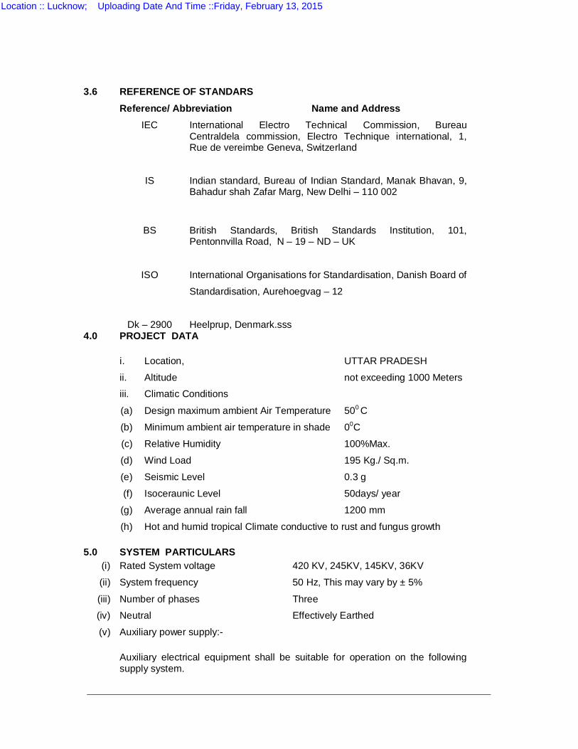
3.6 REFERENCE OF STANDARS
Reference/ Abbreviation Name and Address IEC
International Electro Technical Commission, Bureau Centraldela commission, Electro Technique international, 1, Rue de vereimbe Geneva, Switzerland
IS
Indian standard, Bureau of Indian Standard, Manak Bhavan, 9, Bahadur shah Zafar Marg, New Delhi – 110 002
BS British Standards, British Standards Institution, 101, Pentonnvilla Road, N – 19 – ND – UK
ISO
International Organisations for Standardisation, Danish Board of
Standardisation, Aurehoegvag – 12
Dk – 2900 Heelprup, Denmark.sss 4.0 PROJECT DATA i. Location, UTTAR PRADESH
ii. Altitude not exceeding 1000 Meters
iii. Climatic Conditions
(a) Design maximum ambient Air Temperature 500 C
(b) Minimum ambient air temperature in shade 00C
(c) Relative Humidity 100%Max.
(d) Wind Load 195 Kg./ Sq.m.
(e) Seismic Level 0.3 g
(f) Isoceraunic Level 50days/ year
(g) Average annual rain fall 1200 mm
(h) Hot and humid tropical Climate conductive to rust and fungus growth 5.0 SYSTEM PARTICULARS
(i) Rated System voltage 420 KV, 245KV, 145KV, 36KV
(ii) System frequency 50 Hz, This may vary by ± 5%
(iii) Number of phases Three
(iv) Neutral Effectively Earthed
(v) Auxiliary power supply:- Auxiliary electrical equipment shall be suitable for operation on the following
supply system.
Location :: Lucknow; Uploading Date And Time ::Friday, February 13, 2015
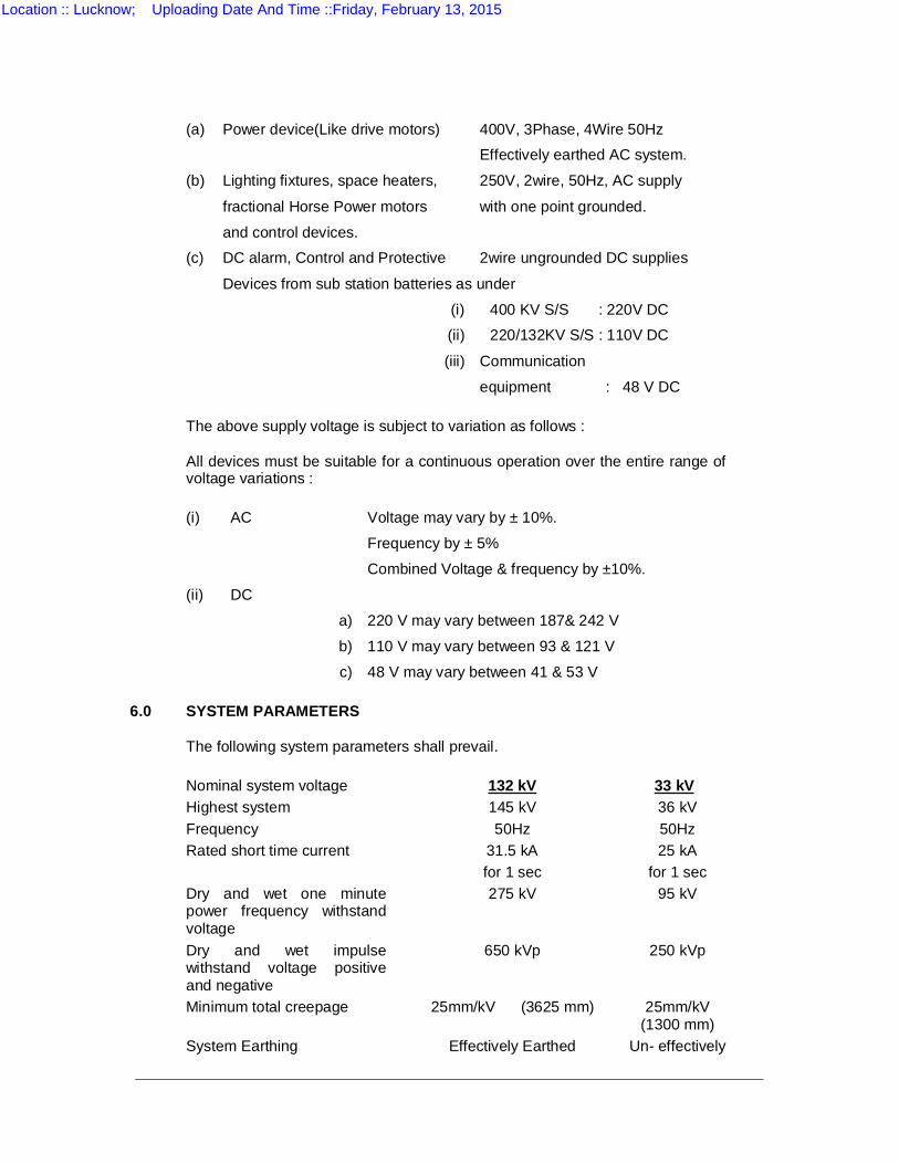
(a) Power device(Like drive motors) 400V, 3Phase, 4Wire 50Hz
Effectively earthed AC system.
(b) Lighting fixtures, space heaters, 250V, 2wire, 50Hz, AC supply
fractional Horse Power motors with one point grounded.
and control devices.
(c) DC alarm, Control and Protective 2wire ungrounded DC supplies
Devices from sub station batteries as under
(i) 400 KV S/S : 220V DC
(ii) 220/132KV S/S : 110V DC
(iii) Communication
equipment : 48 V DC The above supply voltage is subject to variation as follows : All devices must be suitable for a continuous operation over the entire range of
voltage variations : (i) AC Voltage may vary by ± 10%.
Frequency by ± 5%
Combined Voltage & frequency by ±10%.
(ii) DC
a) 220 V may vary between 187& 242 V
b) 110 V may vary between 93 & 121 V
c) 48 V may vary between 41 & 53 V 6.0 SYSTEM PARAMETERS The following system parameters shall prevail. Nominal system voltage 132 kV 33 kV
Highest system 145 kV 36 kV Frequency 50Hz 50Hz Rated short time current 31.5 kA
for 1 sec 25 kA
for 1 sec Dry and wet one minute power frequency withstand voltage
275 kV 95 kV
Dry and wet impulse withstand voltage positive and negative
650 kVp 250 kVp
Minimum total creepage 25mm/kV (3625 mm) 25mm/kV (1300 mm)
System Earthing Effectively Earthed Un- effectively
Location :: Lucknow; Uploading Date And Time ::Friday, February 13, 2015
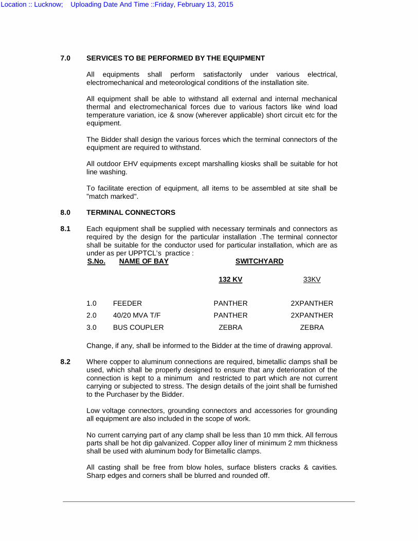
7.0 SERVICES TO BE PERFORMED BY THE EQUIPMENT All equipments shall perform satisfactorily under various electrical,
electromechanical and meteorological conditions of the installation site. All equipment shall be able to withstand all external and internal mechanical
thermal and electromechanical forces due to various factors like wind load temperature variation, ice & snow (wherever applicable) short circuit etc for the equipment.
The Bidder shall design the various forces which the terminal connectors of the
equipment are required to withstand. All outdoor EHV equipments except marshalling kiosks shall be suitable for hot
line washing. To facilitate erection of equipment, all items to be assembled at site shall be
"match marked". 8.0 TERMINAL CONNECTORS 8.1 Each equipment shall be supplied with necessary terminals and connectors as
required by the design for the particular installation .The terminal connector shall be suitable for the conductor used for particular installation, which are as under as per UPPTCL’s practice :
S.No. NAME OF BAY SWITCHYARD 132 KV 33KV
1.0 FEEDER PANTHER 2XPANTHER
2.0 40/20 MVA T/F PANTHER 2XPANTHER
3.0 BUS COUPLER ZEBRA ZEBRA Change, if any, shall be informed to the Bidder at the time of drawing approval. 8.2 Where copper to aluminum connections are required, bimetallic clamps shall be
used, which shall be properly designed to ensure that any deterioration of the connection is kept to a minimum and restricted to part which are not current carrying or subjected to stress. The design details of the joint shall be furnished to the Purchaser by the Bidder.
Low voltage connectors, grounding connectors and accessories for grounding
all equipment are also included in the scope of work. No current carrying part of any clamp shall be less than 10 mm thick. All ferrous
parts shall be hot dip galvanized. Copper alloy liner of minimum 2 mm thickness shall be used with aluminum body for Bimetallic clamps.
All casting shall be free from blow holes, surface blisters cracks & cavities.
Sharp edges and corners shall be blurred and rounded off.
Location :: Lucknow; Uploading Date And Time ::Friday, February 13, 2015
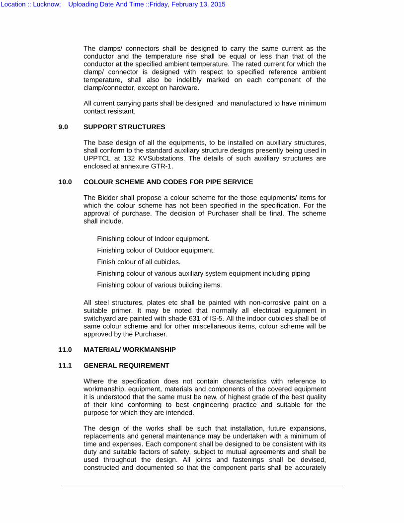
The clamps/ connectors shall be designed to carry the same current as the conductor and the temperature rise shall be equal or less than that of the conductor at the specified ambient temperature. The rated current for which the clamp/ connector is designed with respect to specified reference ambient temperature, shall also be indelibly marked on each component of the clamp/connector, except on hardware.
All current carrying parts shall be designed and manufactured to have minimum
contact resistant. 9.0 SUPPORT STRUCTURES The base design of all the equipments, to be installed on auxiliary structures,
shall conform to the standard auxiliary structure designs presently being used in UPPTCL at 132 KVSubstations. The details of such auxiliary structures are enclosed at annexure GTR-1.
10.0 COLOUR SCHEME AND CODES FOR PIPE SERVICE The Bidder shall propose a colour scheme for the those equipments/ items for
which the colour scheme has not been specified in the specification. For the approval of purchase. The decision of Purchaser shall be final. The scheme shall include.
Finishing colour of Indoor equipment.
Finishing colour of Outdoor equipment.
Finish colour of all cubicles.
Finishing colour of various auxiliary system equipment including piping
Finishing colour of various building items.
All steel structures, plates etc shall be painted with non-corrosive paint on a suitable primer. It may be noted that normally all electrical equipment in switchyard are painted with shade 631 of IS-5. All the indoor cubicles shall be of same colour scheme and for other miscellaneous items, colour scheme will be approved by the Purchaser.
11.0 MATERIAL/ WORKMANSHIP 11.1 GENERAL REQUIREMENT Where the specification does not contain characteristics with reference to
workmanship, equipment, materials and components of the covered equipment it is understood that the same must be new, of highest grade of the best quality of their kind conforming to best engineering practice and suitable for the purpose for which they are intended.
The design of the works shall be such that installation, future expansions,
replacements and general maintenance may be undertaken with a minimum of time and expenses. Each component shall be designed to be consistent with its duty and suitable factors of safety, subject to mutual agreements and shall be used throughout the design. All joints and fastenings shall be devised, constructed and documented so that the component parts shall be accurately
Location :: Lucknow; Uploading Date And Time ::Friday, February 13, 2015
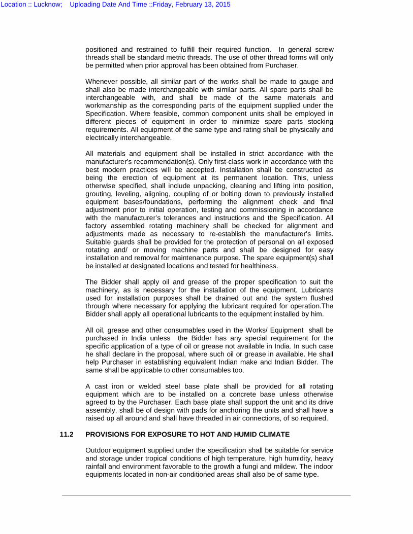
positioned and restrained to fulfill their required function. In general screw threads shall be standard metric threads. The use of other thread forms will only be permitted when prior approval has been obtained from Purchaser.
Whenever possible, all similar part of the works shall be made to gauge and
shall also be made interchangeable with similar parts. All spare parts shall be interchangeable with, and shall be made of the same materials and workmanship as the corresponding parts of the equipment supplied under the Specification. Where feasible, common component units shall be employed in different pieces of equipment in order to minimize spare parts stocking requirements. All equipment of the same type and rating shall be physically and electrically interchangeable.
All materials and equipment shall be installed in strict accordance with the
manufacturer’s recommendation(s). Only first-class work in accordance with the best modern practices will be accepted. Installation shall be constructed as being the erection of equipment at its permanent location. This, unless otherwise specified, shall include unpacking, cleaning and lifting into position, grouting, leveling, aligning, coupling of or bolting down to previously installed equipment bases/foundations, performing the alignment check and final adjustment prior to initial operation, testing and commissioning in accordance with the manufacturer’s tolerances and instructions and the Specification. All factory assembled rotating machinery shall be checked for alignment and adjustments made as necessary to re-establish the manufacturer’s limits. Suitable guards shall be provided for the protection of personal on all exposed rotating and/ or moving machine parts and shall be designed for easy installation and removal for maintenance purpose. The spare equipment(s) shall be installed at designated locations and tested for healthiness.
The Bidder shall apply oil and grease of the proper specification to suit the
machinery, as is necessary for the installation of the equipment. Lubricants used for installation purposes shall be drained out and the system flushed through where necessary for applying the lubricant required for operation.The Bidder shall apply all operational lubricants to the equipment installed by him.
All oil, grease and other consumables used in the Works/ Equipment shall be
purchased in India unless the Bidder has any special requirement for the specific application of a type of oil or grease not available in India. In such case he shall declare in the proposal, where such oil or grease in available. He shall help Purchaser in establishing equivalent Indian make and Indian Bidder. The same shall be applicable to other consumables too.
A cast iron or welded steel base plate shall be provided for all rotating
equipment which are to be installed on a concrete base unless otherwise agreed to by the Purchaser. Each base plate shall support the unit and its drive assembly, shall be of design with pads for anchoring the units and shall have a raised up all around and shall have threaded in air connections, of so required.
11.2 PROVISIONS FOR EXPOSURE TO HOT AND HUMID CLIMATE
Outdoor equipment supplied under the specification shall be suitable for service and storage under tropical conditions of high temperature, high humidity, heavy rainfall and environment favorable to the growth a fungi and mildew. The indoor equipments located in non-air conditioned areas shall also be of same type.
Location :: Lucknow; Uploading Date And Time ::Friday, February 13, 2015
12.0 SPACE HEATERS The heaters shall be suitable for continuous operation at 240 V AC supply. On-
off switch and fuse shall be provided for the heater. One or more adequately rated thermostatically connected heaters shall be
supplied to prevent condensation in any compartment. The heaters shall be installed in the lower portion of the compartment and electrical connections shall be made form below the heaters to minimize deterioration of supply wire insulation. The heaters shall be suitable to maintain the compartment temperature to prevent condensation.
The heaters shall be suitably designed to prevent any contact between the
heater wire and the air and shall consist of-coiled resistance wire centered in a metal sheath and completely encased in a highly compacted powder of magnesium oxide or other material having equal heat conduction and electrical insulation properties, or they shall consist of resistance wire wound on a ceramic and completely covered with a ceramic material to prevent any contact between the wire and the air. Alternatively, they shall consist of a resistance wire mounted into a tubular ceramic body built into an envelop of stainless steel or the resistance wire is wound on a tubular ceramic body and embedded in glaze. The surface temperature of the heaters shall be restricted to a value which will not shorten the life of the heater sherns or that of insultor wire or other component in the compartments.
13.0 FUNGISTATIC VARNISH Besides the space heaters, special moisture and fungus resistant varnish shall
be applied on parts which may be subjected or predisposed to the formation of fungi due to the presence or deposit of nutrient substances. The varnish shall not be applied to any surface or part where the treatment will interface with the operation or performance of the equipment. Such surfaces or parts shall be protected against the application to the varnish.
14.0 VENTILATION OPENING In order to ensure adequate ventilation, compartments shall have ventilation
openings provided with fine wire mesh of brass to prevent the entry of insects and to reduce to a minimum the entry of dirt and dust. Outdoor compartment openings shall be provided with shutter type blinds.
15.0 DEGREE OF PROTECTION The enclosures of the Control Cabinets, junction boxes and Marshalling Boxes,
panels etc to be installed shall be provided with degree of protection as detailed here under:
a) Installed out door : IP-55
b) Installed indoor in air conditioned area : IP-31
c) Installed in covered area : IP -52
d) Installed indoor- in non air-conditioned area where possibility of entry of water is limited: IP-41
e) For LT Switchgear (AC & DC distribution Boards): IP-52
Location :: Lucknow; Uploading Date And Time ::Friday, February 13, 2015
The degree of protection shall be in accordance with IS:13947, (Part-1)/IEC-947
(Part-1). Type test report/or degree of protection test. on each type of the box shall be submitted for approval.
16.0 RATING PLATES, NAME PLATES AND LABELS Each main and auxiliary item of substation is to have permanently attached to it
in a conspicuous position a rating plate of non-corrosive material upon which is to be engraved manufacturer’s name, year of manufacture, equipment name, type or serial number together with details of the loading conditions under which the item of substation in question has been designed to operate and such diagram plates as may be required by the Purchaser. The rating plate of each equipment shall be according to IEC requirement.
All such nameplates, Instructions plates, rating plates shall be bilingual with
Hindi inscription first followed by English. Alternatively two separate plates one with Hindi and the other with English inscriptions may be provided.
17.0 FIRST FILL OF CONSUMABLES, OIL AND LUBRICANTS All the first fill of consumables such as oils, lubricants, filling compounds, touch
up paints, soldering/brazing material for all copper piping of circuit breakers and essential chemicals etc. which will be required to put the equipment, covered under the scope of the specifications, into successful operation, shall be furnished by the Bidder unless specifically excluded under the exclusions in these specifications and documents.
18.0 PROTECTION All coated surfaces shall be protected against abrasion, impact, discolouration
and any other damages. All exposed threaded portions shall be suitably protected with either a metallic or a non-metallic protection device. All ends of all valves and pipings and conduit equipment connections shall be properly sealed with suitable devices to protect them from damage. The parts which are likely to get rusted, due to exposure to weather should also be property treated and protected in a suitable manner.
19.0 SURFACE FINISH All interiors and exteriors of tanks, control cubicles and other metal parts shall
be thoroughly cleaned to remove all rust, scales, corrosion, creases or other adhering foreign matter. All steel surfaces in contact with insulating oil as far as accessible shall be painted with not less than two coats of heat resistant, oil insoluble, insulating paints.
All metal surfaces exposed to atmosphere shall be given two primer coats of
zinc chromate and two coats of epoxy paint with epoxy base thinner. All metal parts not accessible for painting shall be made of corrosion resisting material. All machine finished or bright surfaces shall be coated with a suitable preventive compound and suitably wrapped or other wise protected. All paints shall be carefully selected to withstand tropical heat and extremes of weather within the limit specified. The paint shall not scale off or wrinkle or be removed by abrasion due to normal handling.
All external painting shall be as per shade No. 631 of IS: 5.
Location :: Lucknow; Uploading Date And Time ::Friday, February 13, 2015
20.0 GALVANISING All ferrous parts including all sizes of nuts, bolts, plain and spring washers,
support channels, structures, shall be hot dip galvanized conforming to latest version of IS:2629 or any other equivalent authoritative standard. However, hardware less than M12 size shall be electro-galvanized. Minimum weight of zinc coating shall be 610 gm/ sq.mm and minimum thickness of coating shall be 85 microns for all items thicker than 6 mm. For items lower than 6mm thickness, requirement of coating shall be as per relevant ASTM.
21.0 PROTECTIVE GUARDS Suitable guards shall be provided for protection of personnel on all exposed
rotation and/of moving machine parts. All such guards with necessary spares and accessories shall be designed for easy installation and removal for maintenance purpose.
22.0 TOOLS AND TACKLES The Bidder shall supply with the equipment one complete set of all special tools
and tackles for the erection, assembly, dis-assembly and maintenance of the equipment. However, these tools and tackles shall be separately packed and brought on to site.
23.0 CONTROL CABINETS, JUNCTION BOXES, TERMINAL BOXES &
MARSHALLING BOXES FOR OUTDOOR EQUIPMENT All types of boxes, cabinets etc. shall generally conform to & be tested in
accordance with IS-5039/ IS-8623, IEC-439, as applicable, and the clauses given below.
Control cabinets, junction boxes, marshalling boxes & terminal boxes shall be
made of sheet steel or aluminum enclosure and shall be dust, water and vermin proof. Sheet steel used shall be at least 2.0 mm thick cold rolled or 2.5 mm hot rolled. The box shall be properly braces to prevent wobbling. There shall be sufficient reinforcement to provide level surfaces, resistance to vibrations and rigidity during transportation and installation. In case of aluminum enclosed box, the thickness of aluminum shall be such that it provides adequate rigidity and long life as comparable with sheet steel of specified thickness.
Cabinet/boxes shall be free standing floor mounting type, wall mounting type or
pedestal mounting type as per requirements. Cabinet/boxes shall be provided with double hinged doors with padlocking
arrangements. The distance between two hinges shall be adequate to ensure uniform sealing pressure against atmosphere. The quality of the gasket shall be such that it does not get damaged/cracked during the operation of the equipment.
All doors, removable covers and plates shall be provided gasket all around with
suitably profiled EPDM gaskets. The gasket shall be tested in accordance with approved quality plan. The quality of gasket shall be such that it does not get damaged/cracked during ten years of operation of the equipment or its major overhaul whichever is earlier. All gasketed surfaces shall be smooth straight
Location :: Lucknow; Uploading Date And Time ::Friday, February 13, 2015
and reinforced if necessary to minimize distortion and to make a tight seal. Ventilating Louvers, if provided, shall have screen and filter, the screen shall be fine wire mesh made of brass.
All boxes/ cabinets shall be designed for the entry of cables from bottom by means of weather proof and dust-proof connections. Boxes and cabinets shall be designed with generous clearances to avoid interference between the wiring entering from below and any terminal blocks or accessories mounted within the box or cabinet. Suitable cable gland plate projecting at least 150 mm above the base of the marshalling kiosk/box shall be provided for this purpose along with the proper blanking plates. Necessary number of cable glands shall be supplied and fitted on this gland plate. the gland shall project at least 25 mm above gland plate to prevent entry of moisture in cable crutch. Gland plate shall have provision for some future glands to be provided later, if required.
23.1 EARTHING Positive earthing of the cabinet shall be ensured by providing two separate
earthing pads. The earth wire/ strip shall be terminated on to the earthing pad and secured by the use of self etching washer. Earthing of hinged door shall be done by using a separate earth wire.
The bay marshalling kiosks shall be provided with danger plate and a diagram
showing the numbering/connection/ feruling by pasting the same on the side of the door.
23.2 TESTS The following routine tests alongwith the routine tests as per IS 5039 shall also
be conducted. Check for wiring Visual and dimension check The enclosure of bay marshalling kiosk, junction box, terminal box shall be type
tested for IP-55 as per IS:13947. After IP-55 test, 2.5 kVrms for 2 (one) minute insulation resistance and functional test should be conducted.
23.3 AUXILIARY SWITCHES All the auxiliary switches shall be fully type tested as per relevant IS. 24.0 TERMINAL BLOCKS AND WIRING Control and instrument leads form the switchboards of from other equipment will
be brought to terminal boxes or control cabinets in conduits. All interphase and external connections to equipment or to control cubicles will be made through terminal blocks.*
Terminal blocks shall be 1100 V grade and have continuous rating to carry the
maximum expected current on the terminals. Those shall be of moulded piece, complete with insulated/barriers stud type terminals, washers, nuts and lock nuts. Screw clamp overall insulated, insertion type, rail mounted terminals can be used in place of stud type terminals. But preferably the terminal blocks shall be non-disconnecting stud type equivalent to Elmex type CATM4, phoenix cage clamp type or equivalent. The insulating material of terminal block shall be nylon 6.6 which shall be free of halogens, fluorocarbons etc.
Location :: Lucknow; Uploading Date And Time ::Friday, February 13, 2015
Terminal blocks for current transformer and voltage transformer secondary
leads shall be provided with test links and isolating facilities. The current transformer secondary leads shall also be provided with short circuiting and earthing facilities.
The terminals shall be such that maximum contact area is achieved when a
cable is terminated. The terminal shall have a locking characteristic to prevent cable form escaping form the terminal clamp unless it is done intentionally.
The conducting part in contact with cable shall preferably be tinned or silver
plated. However Nickel plated copper or zinc plated steel shall also be acceptable.
The terminal blocks shall be of extensible design. The terminal blocks shall have locking arrangement to prevent it,s escape from
the mounting rails. The terminal blocks shall be fully enclosed with removable covers of
transparent, non-deterioration type plastic material. Insulating barriers shall be provided between the terminal blocks. These barriers shall not hinder the operator form carrying out the wiring without removing the barriers.
Unless otherwise specified terminal blocks shall be suitable for connecting the following conductors on each side.
a) All circuits except
CT circuits Minimum of 2 nos of 2.5 sq. mm copper flexible
b) All CT circuits Minimum of 4 nos. of 2.5 sq.mm copper flexible
The arrangements shall be in such a manner so that it is possible to safely connect or disconnect terminals on live circuits and replace fuse links when the cabinet is live.
At least 20% spare terminals shall be provided on each panel/ cubicle/box and
these spare terminals shall be uniformly distributed on all terminal rows. There shall be minimum clearance of 250 mm between the first bottom row of
terminal block and the associated cable gland plate. Also the clearance between two rows of terminal blocks shall be a minimum of 150 mm.
The Bidder shall furnish all wire, conduits and terminals for the necessary
interphase electrical connections (where applicable) as well as between phases and common terminal boxes or control cabinets.
All input and output terminals of each control cubicle shall be tested for surge
withstand capability in accordance with the relevant IEC Publications, in both longitudinal and transverse modes. The Bidder shall also provide necessary filtering, surge protection, relays and any other measures necessary to achieve an impulse withstand level at the cable interfaces of the equipment.
25.0 LAMPS AND SOCKETS 25.1 LAMPS : All incandescent lamps shall use a socket base as per IS-1258, except in the
case of signal lamps.
Location :: Lucknow; Uploading Date And Time ::Friday, February 13, 2015
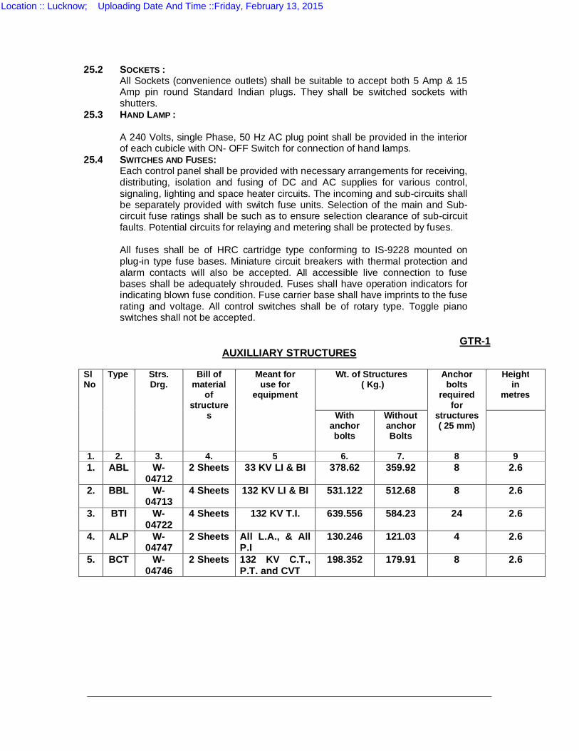
25.2 SOCKETS : All Sockets (convenience outlets) shall be suitable to accept both 5 Amp & 15
Amp pin round Standard Indian plugs. They shall be switched sockets with shutters.
25.3 HAND LAMP : A 240 Volts, single Phase, 50 Hz AC plug point shall be provided in the interior
of each cubicle with ON- OFF Switch for connection of hand lamps. 25.4 SWITCHES AND FUSES: Each control panel shall be provided with necessary arrangements for receiving,
distributing, isolation and fusing of DC and AC supplies for various control, signaling, lighting and space heater circuits. The incoming and sub-circuits shall be separately provided with switch fuse units. Selection of the main and Sub-circuit fuse ratings shall be such as to ensure selection clearance of sub-circuit faults. Potential circuits for relaying and metering shall be protected by fuses.
All fuses shall be of HRC cartridge type conforming to IS-9228 mounted on
plug-in type fuse bases. Miniature circuit breakers with thermal protection and alarm contacts will also be accepted. All accessible live connection to fuse bases shall be adequately shrouded. Fuses shall have operation indicators for indicating blown fuse condition. Fuse carrier base shall have imprints to the fuse rating and voltage. All control switches shall be of rotary type. Toggle piano switches shall not be accepted.
GTR-1
AUXILLIARY STRUCTURES
Sl No
Type Strs. Drg.
Bill of material
of structure
s
Meant for use for
equipment
Wt. of Structures ( Kg.)
Anchor bolts
required for
structures ( 25 mm)
Height in
metres
With anchor bolts
Without anchor Bolts
1. 2. 3. 4. 5 6. 7. 8 9 1. ABL W-
04712 2 Sheets 33 KV LI & BI 378.62 359.92 8 2.6
2. BBL W-
04713 4 Sheets 132 KV LI & BI 531.122 512.68 8 2.6
3. BTI W-
04722 4 Sheets 132 KV T.I. 639.556 584.23 24 2.6
4. ALP W-
04747 2 Sheets All L.A., & All
P.I 130.246 121.03 4 2.6
5. BCT W-04746
2 Sheets 132 KV C.T., P.T. and CVT
198.352 179.91 8 2.6
Location :: Lucknow; Uploading Date And Time ::Friday, February 13, 2015
SECTION VI
FORM ‘A’
General Conditions for the Supply of Plant and the Execution of Works in
Connection with the Schemes in the UPPTCL
1. In construing these General Conditions and the annexed Specification, the
following words shall have the meanings herein assigned to them unless there is anything in the subject or context inconsistent with such construction;
Definition of terms.
"The Purchaser" or the Corporation shall means the UPPTCL and shall include
his successors and assigns.
The "Bidder" shall mean the Bidder whose Bid shall be accepted by the
Purchaser, and shall include such Bidder's heirs, legal representatives successors and assigns.
The "Sub-Bidder" shall mean the person named in the Contract for any part of
the work or any person to whom any part of the Contract has been sublet with the consent in writing of the Engineer and the heirs, legal representatives successors and assigns of such person.
The "Engineer" shall mean the officer placing the order for the work, with the
Bidder and such other officer as may be authorised and appointed in writing by the Purchaser to act as Engineer for the purposes of the Contract and in case no such officer has been so appointed, the Purchaser or his duly authorised representative.
"Plant", “Equipment", "Material", "Work" or "Works" shall mean respectively the
plant and materials to be provided and work or works to be done by the Bidder under the Contract.
The "Contract" shall mean and include the General Conditions, Specifications,
Schedules, Drawings, Form or Bid, Covering Letter, Schedule of Prices, or the final General Conditions, Specifications and Drawings and the Agreement to be entered into under clause 3 of these General Conditions.
"The Specification" shall mean the Specification annexed to these General
Conditions and the Schedules thereto (if any).
The ‘Site’ shall mean the site of the proposed work as detailed in the
Specification or an other place in Uttar Pradesh where work is to be executed under the Contract.
"Tests on Completion" shall mean such tests as are prescribed by the
Specification to be made by the Bidder before the plant is taken over by the Purchaser.
"Commercial Use" shall mean that use of the work which the contract
contemplates or of which it is commercially capable.
"Month" shall mean calendar month. "Writing" shall include any manuscript, typewritten or printed statement under
or over signature or seal as the case may be.
Words importing persons shall include Firms, Companies, Corporations and
other bodies whether incorporated or not.
Location :: Lucknow; Uploading Date And Time ::Friday, February 13, 2015
Words importing the singular only shall also include the plural and vice versa
where the context requires.
2. The Bidder shall be deemed to have carefully examined the General
Conditions, Specifications, Schedules and Drawings. If he shall have any doubt as to the meaning of any portion of these General Conditions or of the Specification, he shall, before signing the Contract, set forth the particulars thereof and submit them to the Engineer in writing, in order that such doubt may be removed.
Bidder to inform himself fully.
3. A formal agreement shall, if required by the Purchaser, be entered into
between the Purchaser and the Bidder for the proper fulfillment of the Contract. Contract.
Further, if required by the Purchaser, the Bidder shall deposit with the
Purchaser as security for the due and faithful performance of the Contract such sums not being less than one per cent of the total value of the Contract as may be fixed by the Purchaser either in case or in any other form approved by the Purchaser. The security deposit shall be refunded to the to the Bidder on the satisfactory completion of tests and the taking over of the plant by the Purchaser.
The charges in respect of vetting and execution of the contract document shall
be borne by the Bidder. The Bidder shall be furnished with an executed stamped counter-part of the Agreement. The import licence fee will in each case have to be paid by the Bidder, import licence may have to be taken in the Corporation's name.
After the Bid has been accepted by the Purchaser, all order or instructions to
the Bidder shall, except as in otherwise provided, be given by the Engineer on behalf of the Purchaser.
4. The Bidder shall submit in duplicate, to the Engineer for his approval,
drawings of the General Arrangement of the works to be carried out and of such detailed drawings, other than shop drawings as may be reasonably necessary.
Contract drawings.
Within fourteen days of the receipt of such drawings the Engineer shall signify
his approval or otherwise of the same, and in the event of his disapproving the drawing, the contactor shall submit further drawings for approval.
Within a reasonable period of the notification by the Engineer to the Bidder of
his approval of such drawings, three sets in ink on tracing cloth or ferrogalic prints mounted on cloth, of the drawings as approved shall be supplied to him by the Bidder and be signed by him and by the Bidder respectively and be thereafter deemed to be the “Contract Drawings”.
These drawings when so signed shall become the property of the Purchaser
and be deposited with the Engineer, and shall not be departed from in any way whatso ever except by the written permission of the Engineer as hereinafter provided. During the execution of the works, one of the sets of drawings shall be available for reference on the site.
In the event of the Bidder desiring to possess a signed set of drawings he shall
supply four sets instead of three sets and in this case the Engineer shall sign the fourth set return the same to the Bidder.
The Bidder if required by the Engineer shall supply in addition copies of any
drawings other than shop drawings which may reasonably be required for the purpose of the Contract and may make a reasonable charge of such copies.
The Engineer, or his duly authorised representative, whose name shall have
previously been communicated in writing to the Bidder, shall have the right, at all reasonable times, to inspect, at the factory of the Bidder, drawings of any portion of
Location :: Lucknow; Uploading Date And Time ::Friday, February 13, 2015
the work.
5. The Bidder shall be responsible for and shall pay for any alterations of the work due to any discrepancies, errors and omission in the drawings or other particulars supplied by him, whether such drawings or particulars have been approved by the Engineer or not, provided that if such discrepancies, errors or omissions are due to inaccurate information or particulars furnished to the Bidder by the Engineer, any alterations in the work necessiated by reason of such inaccurate information or particulars shall be paid for by the Purchaser.
Mistake in drawings.
If any dimensions figured upon a drawing or a plan differ from those obtained
by scaling the drawing or plan, the dimensions as figured upon the drawing or plan shall be taken as correct.
6. The Bidder shall not, without the consent, in writing of the Engineer or
Purchaser, which shall not be unreasonably withheld assign or sublet his Contract, or any substantial part thereof other than for raw materials, for minor details, or for any part of the work of which the makers are named in the Contract, provided that any such consent shall not relieve the Bidder from any obligation, duty, or responsibility under the Contract.
Subletting of Contract.
7. In the event of any claim or demand being made or action being brought
against the Purchaser for infringement or alleged infringement of letters-patent in respect of any machine, plant, work or thing used or supplied by the Bidder under this Contract or in respect of any method of using or working by the Purchaser of such machine, plant, work or thing, the Bidder will indemnify the Purchaser against such claim or demand and all costs and expenses arising from or incurred by reasons of such claim or demand PROVIDED THAT the Purchaser shall notify that Bidder immediately any claim is made and that the Bidder shall be at liberty if he so desires with the assistance of the Purchaser if required but at the Bidder's own expenses, to conduct all negotiations for the settlement of the same or any litigation that may arise therefrom and PROVIDED THAT no such machine, plant, work or thing shall be used by Purchaser for any purpose or in any manner other than for which they have been supplied by the Bidder and specified under this Contract.
Patent rights.
7-A The Bidder shall train at his works--------------Engineer/ Engineers of the
Purchaser in the manufacture and assembly of machinery and its parts for a period of ---------------. A separate agreement for such training shall be signed by the Engineer/ Engineers selected for training, the Purchaser and the Bidder on the form appended hereto.
Training of Engineer.
8. The Plant shall be manufactured and constructed in the best and most
substantial and most workmanlike manner and with materials of the best or of approved qualities for their respective uses.
Quality of material.
9. The Bidder shall be responsible for securely protecting and packing the
plant so as to avoid damage under normal conditions of transport. Packing.
10. The cost of delivering the whole of the material f.o.r. at the railway station
specified or on the site as the specification may define and the cost of packing and unless otherwise agreed, import duties and customs dues shall be borne by the Bidder.
Delivery.
11. Except as hereinafter provided, the Purchaser shall, unless otherwise
specified be responsible for the proper fencing, guarding, lighting and watching of all works other than transmission lines comprised in the Contract and for the proper provision of temporary, roadways, footways, guards and fences as far as the same may be rendered necessary by reason of the work for the
Fencing and lighting for works other than transmission
Location :: Lucknow; Uploading Date And Time ::Friday, February 13, 2015
accommodation and protection of foot-passengers or other traffic and of the owners and occupiers of adjacent property and of the public.
lines.
The Bidder shall at all time provide sufficient fencing, notice boards lights and
watchmen to protect and warn the public and guard the work of transmission lines and in case the Bidder fail to make such provision or the provision made by him is considered by the Purchaser to be inadequate, the Purchaser may make such provisions or further provisions as he may consider necessary and charge the cost thereof to the Bidder.
For transmission lines.
If during the period of erection of a plant the Bidder or his workmen or servants
shall injure or destroy any part of a building or other structure contiguous to the work in progress or if any damage shall be caused from any cause whatsoever to other works (whether in progress or completed) forming part of the work for which the plant is being installed or if any imperfections become apparent in these works the causes of which imperfections are attributable to the Bidder or his workmen or servants, the Bidder shall make good such damages and imperfections and if he fails to do so within a reasonable time, the Purchaser may cause the same to be made good and may deduct the cost thereof from any sum that may then or at any time thereafter become due to the Bidder or from his security deposit or the proceeds of sale thereof or of a sufficient portion thereof or may recover it otherwise.
For all works.
12. No alterations, amendments, omissions, additions, suspensions or
variations of the work (hereinafter referred to as "variations") under the Contract as shown by the Contract drawings of the Specification shall be made by the Bidder except as directed in writing by the Engineer; but the Engineer shall have full power, subject the proviso hereinafter contained, from time to time during the execution of the Contract by notice in writing to instruct the Bidder to make such variation without prejudice to the Contract, and the Bidder shall carry out such instructions and be bound by the same conditions as far as applicable, as through the said variations occurred in the Specification. If any suggested variations would, in the opinion of the Bidder, if carried out, prevent him from fulfilling any of his obligations or guarantees under the Contract, he shall notify the Engineer thereof in writing, and the Engineer shall decide forthwith whether or not the same shall be carried out, and if the Engineer confirms his instructions, the Bidder's obligations and guarantees shall be modified to such an extent as may be justified. The difference of cost, if any occasioned by any such variations, shall be added or deducted from Contract price as the case may require. The amount of such difference, if any, shall be ascertained and determined in accordance with the rates specified in the Schedules of Prices, so far as the same may be applicable and where the rates are not contained in the said Schedules or are not applicable, they shall be settled by the Engineer and Bidder, jointly, as far as possible, before such variations are carried out: Provided that the Purchaser shall not become liable for the payment of any charge in respect of any such variations, unless the instruction for the performance of the same shall have been given in writing by the Engineer.
Power to vary or omit work.
In the event of the Engineer requiring any variations, such reasonable and
proper notice shall be given to the Bidder as will enable him make his arrangements accordingly, and in cases where goods or materials have already been prepared or any designs, drawings or patterns have been made or work done that require to be altered, the Engineer shall allow such compensation in respect thereof as he shall consider reasonable:
Provided that no such variation shall except with the consent in writing of the
Bidder, be such as will involve an increase or decrease of the total price payable under the Contract by more than 10 per cent thereof.
In every case in which the Bidder shall receive instructions from the Engineer
for carrying out any work which either then or later will in the opinion of the Bidder,
Location :: Lucknow; Uploading Date And Time ::Friday, February 13, 2015
involve a claim for additional payment, the Bidder shall, as soon as reasonably possible after the receipt of such instructions, inform the Engineer of such claim for additional payment. 13. If the Bidder shall neglect to execute the work with due deligence and expedition, or shall refuse or neglect to comply with any reasonable orders given him in writing by the Engineer in connexion with work, or shall contravene any provision of Contract the Purchaser may give seven days’ notice in writing to the Bidder, to make good the failure, neglect or contravention complained of and if the Bidder shall fail to comply with the notice within a reasonable time from the date of service thereof in the case of a failure, neglect, or contravention capable of being made good within that time, then and in such case the Purchaser shall be at liberty to employ other workmen and forth with perform such work as the Bidder may have neglected to do, or if the Purchaser shall think fit, it shall be lawful for him to take the work wholly, or in part out of the Bidder's hands and give it to another person on contract at a reasonable price or provided any other materials, tools, tackle or labour for the purpose of completing the work, or any part thereof, and in that event the Purchaser shall, without being responsible to the Bidder for fair wear and tear of the same, have the free use of all the materials, tools, tackle, or other things which may be on the site, for use at any time in connection with the work to the exclusion of any right of the Bidder over the same, and the Purchaser shall be entitled to retain and apply any balance which may be otherwise due on the Contract by him to the Bidder such part thereof as may be necessary, to the payment of the cost of executing such work as aforesaid.
Negligence.
If the cost of executing the work as aforesaid shall exceed the balance due to
the Bidder, and the Bidder fails to make good the deficiency the Purchaser may recover it from the Bidder in any lawful manner or the Purchaser may sell the said materials, tools, tackle or other things belonging to the Bidder, and the proceeds of such sale shall be applied towards the payment of such deficiency and the costs of and incidental to such sale and any balance remaining after crediting the same shall be paid to the Bidder on the certificate of the Engineer, provided that when all expenses, cost and charges incurred in the completion of the work are paid by the Bidder, all such materials, tools, tackle or other things remaining unsold shall be removed by the Bidder.
14. If the Bidder shall die or commit any act of bankruptcy, or being a
corporation commence to be wound up except for reconstruction purposes or carry on its business under a Receiver, the executors, successors or other representative in law of the estate of the Bidder or any such Receiver Liquidator or any person in whom, the Contract may become vested shall forthwith give notice thereof in writing to the Purchaser and shall for one month during which he shall take all reasonable steps to prevent a stoppage of the works, have the option of carrying out the Contract subject to his or their providing such guarantee as may be required by the Purchaser but not exceeding the value of the work for the time being remaining unexecuted. In the event of stoppage of the works the period of the option under this clause shall be fourteen days only: Provided that should the above option not be exercised, the Bidder may be determined by the Purchaser by notice in writing to the Bidder and the Purchaser may exercise the same power which he could have under the proceeding clause if the work had been taken out of Bidder's hands under that clause.
Death, Bankruptcy etc.
15. The Engineer and his duly authorized representatives shall have and at
all reasonable times access to the Bidder's premises, and shall have the power at all reasonable times to inspect and examine the materials and workmanship of the plant during its manufacture there; and if part of the plant is being manufactured on other premises the Bidder shall obtain for the Engineer and for his duly authorised representative permission to inspect it as the plant was manufactured on the Bidder's own premises.
Inspection.
Location :: Lucknow; Uploading Date And Time ::Friday, February 13, 2015
The Engineer shall, on giving seven days’ notice in writing to the Bidder setting out any grounds of objections which he may have in respect of the work, be at liberty to reject all or any part or workmanship connected with such work which in his opinion are not in accordance with the Contract or are in his opinion defective for any reason whatever : Provided that, if such notice be not sent to the Bidder within reasonable time after the grounds upon which such notice is based have come to the knowledge of the Engineer he shall not be entitled to reject the said plant or workmanship on such grounds Unless specifically provided otherwise all tests shall be made at the Bidder's work before shipment.
The Bidder shall, if required give the Engineer notice of any materials being
ready for testing, and the Engineer or his said representative if so desired shall, on giving twenty-four hours’ previous notice in writing to the Bidder, attend at the Bidder's premises within seven days of the date on which the material is notified as being ready, failing which visit the Bidder may proceed with the tests which shall be deemed to have been made in the Engineer’s presence, and he shall forthwith forward to the Engineer duly certified copies of the tests in duplicate.
In all cases where the Bidder provides for tests whether at the premises of the
Bidder or of any Sub-Bidder, the Bidder, except where otherwise specified shall provide free of charges such labour, materials, electricity, fuel, water stores, apparatus and instruments as may reasonably be demanded to carry out efficiently such tests of the plant in accordance with the contract and shall give facilities to the Engineer or to his authorised representative to accomplish such testing.
Test at Bidder's premises.
If special tests other than those specified in the Contract are required they
shall be paid for by the Purchaser as “variations" under clause 12.
When the tests have been satisfactorily completed at the Bidder's works the
Engineer shall issue a certificate to the effect.
In all cases where the Contract provides for test on the site the Purchaser,
except where otherwise specified, shall provide, free of charges, such labour, materials, electricity, fuel, water, stores apparatus and instruments as may be required from to time and as may reasonably be demanded efficiently to carry out such test of the plant or workmanship in accordance with Contract. In the case of the Bidder requiring electricity for tests on site such electricity shall be supplied to the Bidder in the most convenient form available.
Test on site.
16. No plant shall be forwarded until shipping instruction shall have been
given to the Bidder. Delivery of plant.
Notification of delivery or dispatch in regard to each and every consignment
shall be made to the Purchaser immediately after dispatch or delivery. The supplier shall further supply to the consignee a priced invoice and packing account of all stores delivered or dispatched by him. All packages, containers, bundles and loose materials forming part of each and every consignment shall be described fully in the packing account, and full details of the content of packages and quantity of materials shall be given to enable the consignee to check the stores on arrival at destination.
17. The suitable access to and possession of the site shall be afforded to the
Bidder by the Purchaser in reasonable time, and the Purchaser shall have any foundations to be provided by him ready when required by the Bidder. Where a crane is available, its safe lifting capacity shall be stated in the Specification, and it shall be available for free use of the Bidder until the plant is taken over.
Access to site and work on site.
The work, so far as it is carried out on the Purchaser's premises, shall be
carried out at such time as the Purchaser may approve and so as not to interfere unnecessarily with the conduct of the Purchaser's business, but the Purchaser
Only applicable to complete erection
Location :: Lucknow; Uploading Date And Time ::Friday, February 13, 2015
shall give the Bidder all reasonable facilities for carrying out the work. contract.
No person other than the Bidder, Sub-Bidders, and workmen and the Bidder's duly authorized agents shall, except with the special permission in writing of the Engineer or his representative, be allowed to do any work on the site in connection with the erection of the work, but access to the works shall at all times be accorded to the Engineer and his representatives and other authorized officials or representatives of the Purchaser.
The Bidder shall permit the execution of work by other Bidders or tradesmen
whose names shall have been previously communicated in writing to the Bidder by the Engineer, and afford them every facility for the execution of their several works simultaneously with his own.
The Purchaser shall provide all the unskilled labour and facilities necessary for
the execution of work included in the Contract unless otherwise specified.
18. All the work shall be carried out under the direction and to the reasonable
satisfaction of the Engineer. If supervision of the erection or complete erection is included in the Contract, the Bidder shall be responsible for the correctness of the positions, levels and dimensions, of the work according to the drawings notwithstanding that he may have been assisted by the Engineer in setting out the same.
Engineer's supervision.
19. In respect of all matters which are left to the decision of the Engineer,
including the granting or withholding of certificates, the Engineer shall, if required so to do by the Bidder, give in writing a decision thereon and his reason for such decision. If the decision is not accepted by the Bidder the matter will, at the request of the Bidder, be referred to arbitration under the provision for arbitration hereinafter contained but subject to this right of reference to arbitration such decision shall be final and binding on the Bidder.
Engineer's decision.
20. If the supervision of erection or complete erection is also included in the
Contract, the Bidder shall employ at least one competent representative, and whose name or names shall have previously been communicated in writing to the Engineer by the Bidder to superintend the erection of the plant and the carrying out of the works. The said representative, or if more than one shall be employed then one of such representatives, shall be present on the site during working hours, and any written orders or instructions which the Engineer or his duly authorized representative whose name shall have been previously communicated in writing to the Bidder may give to the said representative of the Bidder shall be deemed to have been given to the Bidder.
Bidder's representatives and workmen.
The Engineer shall be at liberty to object to any representative or person
employed by the Bidder in the execution of or otherwise about the works who shall in his opinion misconduct himself or be incompetent or negligent and the Bidder shall remove the person so objected to upon receipt from the Engineer of notice in writing requiring him to do so and shall provide in his place a competent representative at the Bidder's expense
The Purchaser shall provide suitable living accommodation on the site for the
use of Bidder's representative unless the Bidder exempts him from this liability.
21. The Bidder shall be responsible for loss, damage or depreciation of the
plant until the same is taken over under clause 35 or is deemed under that clause to have been taken over : Provided always that the Bidder shall not be responsible for any such loss, damage and depreciation occurring during such period that the plant is operated by the Purchaser's staff prior to being taken over in accordance with clause 35.
Liability for accidents and damage.
Location :: Lucknow; Uploading Date And Time ::Friday, February 13, 2015
Until the plant is taken over is deemed to have been taken over as aforesaid, the Bidder shall also be liable for and shall indemnify the Purchaser in respect of all injury to person or damage to property resulting from the negligence of the Bidder or his workmen or sub-Bidders or from defective design, or work, but not from other cause :
Provided that the Bidder shall not be liable for any loss of profit or loss of
Contract or any other claim made against the Purchaser not already provided for in the Contract, not for any injury or damage caused by or arising from the acts of the Purchaser or of any other person or due to circumstances over which the Bidder has no control, nor shall his total liability for loss, damage, or injury in this clause exceed the total value of Contract.
The Bidder will indemnify and save harmless the Purchaser against all actions,
suits, claims, demands, costs, or expenses arising in connexion with injuries (other than such as may be attributable to the Purchaser or his employees) suffered prior to the date when the plant shall have been taken over under clause 35 here of by persons employed by the Bidder or his sub-Bidder on the work, whether at Common Law or under the Workmen's Compensation Act, 1923 or any other statute in force at the date of contract relating to the question of the liability of employers for injuries suffered by employees, and will if called upon to do so take out the necessary policy of insurance to cover such indemnity.
In the event of any claim being made, or action brought against the Purchaser
involving the Bidder and arising out of the matters referred to and in respect of which the Bidder is liable under this clause, the Bidder shall be immediately notified there of and he shall with the assistance, if he so requires, of the Purchaser but at the sole expense of the Bidder conduct all negotiations for the settlement of the same or any litigation that may arise therefrom. In such case, the Purchaser shall, at the request and expense of the Bidder, afford all reasonable and available assistance for any such purpose.
Only applicable complete erection Contract.
22. The Bidder shall insure the plant, and shall keep it insured against loss by
theft, destruction or damage by fire, flood, under exposure to the weather, or through riot, civil commotion, war or rebellion, for the full value of the plant from the time of delivery of f.o.b. British Port until the plant is taken over under clause 35. This insurance shall also cover loss by theft on site in the case of Contracts where the Bidder is responsible for complete erection, but not in other cases,
Insurance.
23. If during the progress of the work the Engineer shall decide and notify in
writing to the Bidder that the Bidder has executed any unsound or imperfect work or has supplied any plant inferior in quality to that specified the Bidder on receiving details of such defects or deficiency shall, at his own expense, within such time as may be reasonably necessary for making it good, proceed to alter, reconstruct or remove such work, or supply fresh materials up to the standard of the Specification and in case the Bidder shall fail so to do, the Purchaser may, on giving the Bidder seven days’ notice in writing of his intention so to do, proceed to remove the work complained of, and, at the cost of the Bidder, perform all such work or supply all such material, provided that nothing in this clause shall be deemed to deprive the Purchaser of or affect any right under the contract, which he may otherwise have in respect of such defects or deficiencies.
Replacement of defective work or materials.
24. All costs, damages expenses which the Purchaser may have paid, for
which under the Contract the Bidder is liable, may be deducted by the Purchaser from any moneys due or which may become due by him to the Bidder under the Contract, or may be recovered by suit or otherwise from the Bidder.
Deductions from contract price.
Any sum of money due and payable, to the Bidder (including security deposit
returnable to him) under this contract may be appropriated by the Purchaser and set off against any claim of the Purchaser for the payment of a sum of money
Location :: Lucknow; Uploading Date And Time ::Friday, February 13, 2015
arising out of or under any other contract made by the Bidder with the Purchaser.
25 (1) Subject to any deduction which the Purchaser may be authorized to make under the Contract, or subject to any additions or deductions provided for under clause 12, the Bidder shall be entitled to payments as follows:
Terms of payment.
(a) Eighty per cent of the f.o.r. Contract value of the plant in rupees on receipt
by the Purchaser of the Bidder's invoice giving the number and date of railway receipt covering the dispatch of the plant from Indian Port and of the advice note giving case number and contents, together with a certificate by the Bidder to the effect that the plant detailed in the said advice note has actually been dispatched under the said railway receipt and that the Contract value of the said plant so dispatched is not less than the amount entered in the invoice.
(b) Ten per cent of the f.o.r. Contract value of the plant on satisfactory
completion of test and taking over of the plant.
(c) Ten percent of the f.o.r. Contract value of the plant at the end of twelve
month from the date of taking over.
(d) For the erection of the plant, in proportion of the progress of the work on
the receipt by the Purchaser of monthly invoices submitted by the Bidder supported by the certificates of the Engineer.
(2) If the time at which either of the instalments due under sub-clauses (b)
and (c) of clause (1) hereof become payable there are minor defects in the plant which are not of such importance as to effect the full commercial use of the plant, then the Purchaser shall be entitled to retain only such part of the instalment then due as represents the cost of making good such minor defects and any sum so retained shall, subject to the provisions of clause 36 become due upon such minor defects being made good.
(3) If the Purchaser desires that the plant or any portion thereof should not be
dispatched by the Bidder when it is due for dispatch, the Bidder shall store such plant or portion at his works and be responsible for all risk . For such storage the Purchaser shall pay to the Bidder at a rate to be mutually agreed upon between the parties but not exceeding 5s (Five shillings) per ton per week, payable quarterly plus interest at one per cent per annum above the current rate of the State Bank of India on 80 per cent of the Contract value of the plant or portion thereof so stored, for the period from the date on which the said plant or portion become due and is ready for shipment up to the date on which it is actually shipped.
25. A. In the event of the supplier / Bidder / company not being able to supply
the materials or to carry out works in accordance with the terms of this contract, the Government / Purchaser / Owner shall have the right to recover any sum advanced in accordance with the clause 25 from the supplier / Bidder / company and from his / its assets.
26. In any case where the Contract price includes a provisional sum to be
provided by the Bidder for meeting the expense of extra work or for work to be done or materials to be supplied by a Sub-Bidder, such sum shall be expended or used, either wholly or in part, or be not used, at the discretion of the Engineer and entirely as he may decide and direct. If no part or only a part thereof be used then the whole or the part not used as the case may be, shall be deducted from the Contract price. If the sum used is more than such provisional sum the Bidder shall pay the excess. In the case of materials supplied on work done by a Sub- Bidder the total of the net sums paid to the Sub-Bidder on account of such materials or
Provisional sums.
Location :: Lucknow; Uploading Date And Time ::Friday, February 13, 2015
work and a sum equal to 10 per cent of such net sum allowed as Bidder's profit shall be deemed to be the sum used. None of the works or articles to which such sum of money refers shall be done or purchased without the written order of the Engineer. The Bidders shall allow the Sub-Bidders every facility for the supply of materials or execution of their several works simultaneously with his own and shall within fourteen days after the Engineer has requested him in writing so to do, pay the dues of such Sub-Bidders on account of such materials or work PROVIDED ALWAYS that the Bidder shall have no responsibility with regard to such work or articles unless he shall have previously approved the Sub-Bidder and/or the material or plant to be supplied.
27. Every application to the Engineer for a certificate must be accompanied by a detailed invoice (in duplicate) setting forth in the order of the Schedule of prices, particulars of the work executed, and the certificate as to such plant or work as in the reasonable opinion of the Engineer in accordance with the Contract shall be issued within fourteen days if possible or for other than ( the first payment within such time of application for ) the same as is reasonably necessary for communication with the site.
Certificates of Engineer.
The Engineer may by any certificate make any correction or modification in any
previous certificate which shall have been issued by him and payments shall be regulated and adjusted accordingly.
28. Payment shall be due and payable by the Purchaser in accordance with
the provisions of clause 25 hereof at the end of the month following that in which invoices for the amounts due together with necessary documents are received by the Purchaser, provided that the Purchaser shall not be bound to make any payment represents at least 8 percent of the total Contract value of the plant.
Due dates of payment.
29. (1) No certificate of the engineer on account nor any sum paid on account
by the Purchaser, nor any extension of time granted under clause 31 shall effect or prejudice the rights of the Purchaser against the Bidder either under this Agreement or under the law or relieve the Bidder of his obligations for the due performance of the Contract, or be interpreted as approval of the work done or of the materials supplied.
Certificates not to affect rights of the Purchaser or Bidder.
(2) No certificate of the Engineer shall create liability in the Purchaser to pay
for any alterations, amendments, variations or additional work not ordered in writing by the Engineer or absolve the Bidder of his liability for the payment of damages whether due, ascertained or certified or not of any sum against the payment of which he is bound to indemnify the Purchaser nor shall any such certificate nor the acceptance by him of any sum paid on account or otherwise affect or prejudice the rights of the Bidder against the Purchaser under this Agreements or under the law.
30. The Purchaser shall pay to the Bidder all reasonable expenses incurred
by the Bidder by reason of suspension of the works of delay in shipment by order in writing of the Purchaser or the Engineer unless such suspension shall be due to some default on the part of the Bidder or Sub-Bidder.
Suspension of works.
31. The time given to the Bidder for despatch, delivery, erection or
completion, as the case may be, shall be reckoned from the date of receipt by the Bidder of the order, together with all necessary information and drawings to enable the work to be put in hand.
Extension of time for completion.
In all cases in which progress shall be delayed by strikes, lockouts, fire,
accident, defective materials, delay in approval of drawings or any cause whatsoever beyond the reasonable Control of the Bidder, and whether such delay or impediment shall occur before or after the time or extended time, for dispatch,
Location :: Lucknow; Uploading Date And Time ::Friday, February 13, 2015

erection or completion, a reasonable extension of time shall be granted. 32. If the Bidder shall fail in the due performance, of his Contract within the
time fixed by the Contract or any extension thereof, the Bidder agrees to accept a reduction of the Contract price by 1/2 (half) per cent per week reckoned on the Contract value of such portion only of the plant as can not in consequence of the delay be used commercially and efficiently during each week between the appointed or extended time as the case may be and the actual time of acceptance under clause 35, and such reduction shall be in full satisfaction of the Bidder's liability for delay but shall not in any case exceed 10 (ten) per cent of the Contract value of such portion of the plant.
Damages for delay in completion.
33. Whenever possible all tests shall be carried out before shipment. Should,
however, it be necessary for the final tests as to performance and guarantees to be held over until the plant is erected at site they shall be carried out in the presence of the Bidder's representative within one month of the completion of erection. If the result of these tests shall not come within the margin specified, the tests shall, if required, be repeated within one month from the date the plant is ready for re-test, and the Bidder shall repay to the Purchaser all reasonable expenses to which he may be put by such tests.
Tests on completion.
34. If the completed plant, or any portion thereof, before it is taken over under
clause 35, be found to be defective, or fail to fulfil the requirements of the Contract, the Engineer shall give the Bidder notice setting fourth particulars of such defects or failure, and the Bidder shall forthwith make the defect good, or alter the same to make it, comply with the requirements of Contract. If the Bidder fails to do so with a reasonable time, the Purchaser may reject and replace, at the cost of the Bidder, the whole or any portion of the plant, as the case may be, which is defective or fails to fulfil the requirements of the Contract, such replacement shall be carried out by the Purchaser within a reasonable time and at a reasonable price, and where reasonably possible to the same specification and under competitive conditions. In case of such replacement by the Purchaser, the Bidder shall be liable to pay to the Purchaser the extra cost, if any, of such replacement delivered and /or erected as provided for the original Contract, such extra cost being the ascertained difference between the price paid by the Purchaser under the provisions above mentioned, for such replacement and the Contract price for the plant so replaced, and also to repay any sum paid by the Purchaser to the Bidder in respect of such defective plant. If the Purchaser does not so replace the rejected plant within a reasonable time, the Bidder shall be liable only to repay to the Purchaser all money paid by the Purchaser to him in respect of such plant.
Rejection of defective plant.
In the event of such rejection, the Purchaser shall be entitled to the use of the plant in reasonable and proper manner for a time reasonably sufficient to enable him to obtain other replacement plant. During the period the rejected plant is used commercially the Bidder shall be entitled to a reasonable sum as payment for such use.
35. Where the specification calls for performance tests before shipment and these have been successfully carried out, the plant shall be accepted and taken over when it has been satisfactorily put into operation on site, or within one month of its being ready to be put into operation, whichever shall be the earlier and the Engineer shall forthwith issue a Taking-over Certificate.
Taking over.
In the event of final or any outstanding test being held over until the plant is erected such, taking-over Certificate shall be issued subject to the results of such final or outstanding tests shall be carried out in accordance with clause 33.
When the specification calls for tests on site the plant shall be taken over and the Taking-over Certificate issued immediately after such tests have been satisfactorily carried out.
If for any reason other than the default of the Bidder such last mentioned tests on site shall not be carried out within one month of notice by the Bidder to the Purchaser of the plant being ready for test the plant shall be deemed to have been taken over as on the last day of the such period and payments due to the Bidder
Location :: Lucknow; Uploading Date And Time ::Friday, February 13, 2015
shall if called upon so to do by the Purchaser, but at the Purchaser's expense, make the said test during the maintenance period and accept as aforesaid under the same obligations as specified in clause 33.
The Engineer shall not delay the issue of any Taking-over Certificate contemplated by this clause on account of minor deficiencies of material or defects in the plant which do not materially affect the commercial use thereof provided that the Bidder shall undertake to make good the same in due course.
36. For a period of 12 (twelve) calendar months commencing from the date on which the plant is taken over or is deemed to have been taken over under clause 35 (called “the maintenance period”) the Bidder shall remain liable to replace any defective parts that may develop in plant of his own manufacture or those of his Sub-Bidders approved under clause 6 under the conditions provided for by the Contract under proper use and arising solely from faulty design, materials or workmanship provided always that such defective parts are not repairable at site and are not essential in the meantime to the maintenance in commercial use of the plant are promptly returned to the Bidder's works at the expenses of the Bidder unless otherwise arranged.
Maintenance.
If it becomes necessary for the Bidder to replace or renew any defective parts
of the plant under this clause, the provisions of the first paragraph of this clause shall apply the parts of the plant so replaced or renewed until the expiration of six months from the date of such replacement or renewal or until the end of the above mentioned period of twelve months, whichever may be the later. If any defects be not remedied within a reasonable time the Purchaser may proceed to do the work at the Bidder's risk and expense, but without prejudice to any other rights which the Purchaser may have against the Bidder in respect of such defects.
The repaired or new parts will be delivered in accordance with clause 10. The Bidder shall bear reasonable cost of minor repairs carried out on his behalf at site.
At the end of the maintenance period the Bidder's liability shall cease. In respect of goods not covered by the first paragraph of this clause, the Purchaser shall be entitled to the benefit of any guarantee given to the Bidder by the original supplier or manufacturer of such goods.
37. The Purchaser shall, throughout the continuance of the Contract and in respect of all matters arising in the performance thereof, serve all notices and obtain all consents, way-leaves, approvals, and permission required in connexion with the regulations and by-laws of any local or other authority which shall be applicable to the works.
Regulations of local authorities.
All work shall be executed in accordance with the Indian Electricity Rules 1956, and any statutory modifications thereof, wherever are applicable, unless otherwise agreed to in writing by the Engineer.
38. If any dispute, difference or controversy shall at any time arise between the Bidder on the one hand and the U.P. Power Transmission Corporation Limited and the Engineer of the Contract on the other touching the Contract, or as the true construction, meaning and intent of any part or condition of the same, or as to manner of execution, or as to the quality or description of, or payment for the same, or as to the true intent, meaning interpretation, construction or effect of the clauses of the contract, specification or drawings or any of them, or as to any thing to be done, ommitted or suffered in pursuance of the contract or specification, or as to the mode of carrying the contract into effect, or as to the breach or alleged breach of the contract, or as to any claims on account of such breach or alleged breach, or as to obviating or compensating for the commission of any such breach, or as to any other matter or thing whatsoever connected with or arising out of the contract, and whether before or during the progress or after the completion of the contract, such question, difference or dispute shall be referred for adjudication to the Chairman U.P. Power Transmission Corporation Limited or to any other person nominated by him in this behalf and his decision in writing shall be final, binding and conclusive. This submission shall be deemed to be a submission to arbitration within the meaning of the Indian Arbitration Act, 1940 or any statutory modification
Arbitration.
Location :: Lucknow; Uploading Date And Time ::Friday, February 13, 2015
thereof. The arbitrator may from time to time with consent of the parties enlarge the time for making and publishing the award.
Upon every or any such reference, the costs of and incidental to the reference
and award respectively shall be in the discretion of the arbitration who shall be competent to determine the amount thereof or direct the same to be taxed as between solicitor and client or as between party and party and to direct by whom and to whom in what manner the same shall be borne and paid.
Work under the contract shall, if reasonably possible, continue, during the
arbitration proceedings, and no payment due or payable by the Corporation shall be withheld on account of such proceedings. In case of refusal / neglect by such nominee Chairman, U.P. Power Transmission Corporation Limited may nominate another person in his place.
38 A. Any action taken or proceedings initiated on any of the terms of this
agreements shall be only in the court of competent Jurisdiction under the High court of Judicature at Allahabad.
Court of Competent Jurisdiction.
39. The contract shall in all respects be constructed and operated as a
Contract as defined in the Indian Contract Act, 1972, and all the payments there-under shall be made in the rupees unless otherwise specified.
Costruction of Contract.
40. The marginal notes to any clause of this Contract shall not affect or
control the construction of such clause.
Marginal Notes
Location :: Lucknow; Uploading Date And Time ::Friday, February 13, 2015
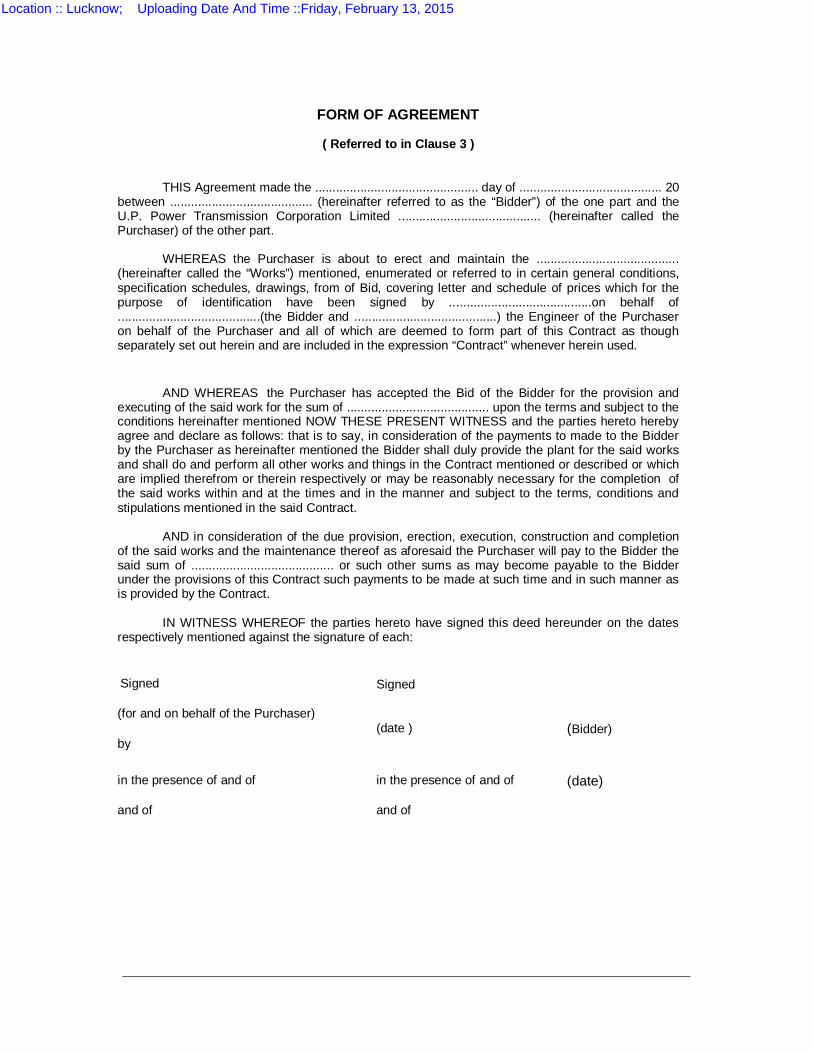
FORM OF AGREEMENT
( Referred to in Clause 3 )
THIS Agreement made the ............................................... day of ......................................... 20 between ......................................... (hereinafter referred to as the “Bidder”) of the one part and the U.P. Power Transmission Corporation Limited ......................................... (hereinafter called the Purchaser) of the other part.
WHEREAS the Purchaser is about to erect and maintain the .........................................
(hereinafter called the “Works”) mentioned, enumerated or referred to in certain general conditions, specification schedules, drawings, from of Bid, covering letter and schedule of prices which for the purpose of identification have been signed by .........................................on behalf of .........................................(the Bidder and .........................................) the Engineer of the Purchaser on behalf of the Purchaser and all of which are deemed to form part of this Contract as though separately set out herein and are included in the expression “Contract” whenever herein used.
AND WHEREAS the Purchaser has accepted the Bid of the Bidder for the provision and
executing of the said work for the sum of ......................................... upon the terms and subject to the conditions hereinafter mentioned NOW THESE PRESENT WITNESS and the parties hereto hereby agree and declare as follows: that is to say, in consideration of the payments to made to the Bidder by the Purchaser as hereinafter mentioned the Bidder shall duly provide the plant for the said works and shall do and perform all other works and things in the Contract mentioned or described or which are implied therefrom or therein respectively or may be reasonably necessary for the completion of the said works within and at the times and in the manner and subject to the terms, conditions and stipulations mentioned in the said Contract.
AND in consideration of the due provision, erection, execution, construction and completion
of the said works and the maintenance thereof as aforesaid the Purchaser will pay to the Bidder the said sum of ......................................... or such other sums as may become payable to the Bidder under the provisions of this Contract such payments to be made at such time and in such manner as is provided by the Contract.
IN WITNESS WHEREOF the parties hereto have signed this deed hereunder on the dates
respectively mentioned against the signature of each: Signed Signed (for and on behalf of the Purchaser) (date ) (Bidder) by
in the presence of and of in the presence of and of (date) and of and of
Location :: Lucknow; Uploading Date And Time ::Friday, February 13, 2015
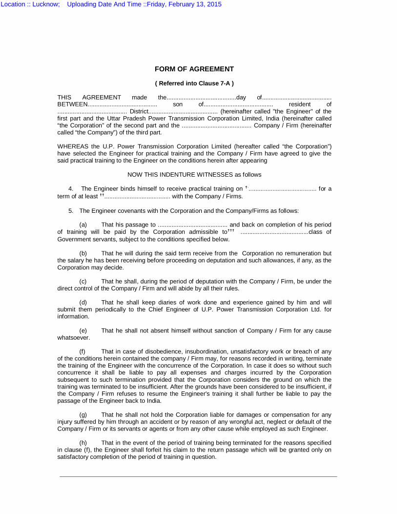
FORM OF AGREEMENT
( Referred into Clause 7-A ) THIS AGREEMENT made the.........................................day of......................................... BETWEEN......................................... son of......................................... resident of ......................................... District......................................... (hereinafter called "the Engineer" of the first part and the Uttar Pradesh Power Transmission Corporation Limited, India (hereinafter called “the Corporation” of the second part and the ......................................... Company / Firm (hereinafter called “the Company”) of the third part. WHEREAS the U.P. Power Transmission Corporation Limited (hereafter called “the Corporation”) have selected the Engineer for practical training and the Company / Firm have agreed to give the said practical training to the Engineer on the conditions herein after appearing
NOW THIS INDENTURE WITNESSES as follows
4. The Engineer binds himself to receive practical training on †......................................... for a
term of at least ††....................................... with the Company / Firms. 5. The Engineer covenants with the Corporation and the Company/Firms as follows:
(a) That his passage to ......................................... and back on completion of his period
of training will be paid by the Corporation admissible to††† ........................................class of Government servants, subject to the conditions specified below.
(b) That he will during the said term receive from the Corporation no remuneration but
the salary he has been receiving before proceeding on deputation and such allowances, if any, as the Corporation may decide.
(c) That he shall, during the period of deputation with the Company / Firm, be under the
direct control of the Company / Firm and will abide by all their rules. (d) That he shall keep diaries of work done and experience gained by him and will
submit them periodically to the Chief Engineer of U.P. Power Transmission Corporation Ltd. for information.
(e) That he shall not absent himself without sanction of Company / Firm for any cause
whatsoever. (f) That in case of disobedience, insubordination, unsatisfactory work or breach of any
of the conditions herein contained the company / Firm may, for reasons recorded in writing, terminate the training of the Engineer with the concurrence of the Corporation. In case it does so without such concurrence it shall be liable to pay all expenses and charges incurred by the Corporation subsequent to such termination provided that the Corporation considers the ground on which the training was terminated to be insufficient. After the grounds have been considered to be insufficient, if the Company / Firm refuses to resume the Engineer's training it shall further be liable to pay the passage of the Engineer back to India.
(g) That he shall not hold the Corporation liable for damages or compensation for any
injury suffered by him through an accident or by reason of any wrongful act, neglect or default of the Company / Firm or its servants or agents or from any other cause while employed as such Engineer.
(h) That in the event of the period of training being terminated for the reasons specified
in clause (f), the Engineer shall forfeit his claim to the return passage which will be granted only on satisfactory completion of the period of training in question.
Location :: Lucknow; Uploading Date And Time ::Friday, February 13, 2015

IN WITNESS WHEREOF the parties hereto have hereunto set their hands the day and the year first above written. Signed by Signed by .............................................................. .............................................................. ( )* ( )* .............................................................** and......................................................... (Engineer) ( )*
In the presence of On behalf of the Corporation and the Company /
Firm in the presence of 1......................................................... 1......................................................... ( )* ( )* .............................................................** ............................................................** 2............................................................. 2............................................................. ( )* ( )* .............................................................** ............................................................** † Nature of traning †† Period ††† Class of Government servant * Name in Capital Letters ** Complete Postal address of person signed.
Location :: Lucknow; Uploading Date And Time ::Friday, February 13, 2015

PROFORMA FOR PERFORMANCE BANK GUARANTEE U.P. POWER TRANSMISSION CORPORATION LIMITED
THIS DEED OF GUARANGEE made on the ……………………day of …………………..by
the……………………….(herein after called “the Guarantor”) of the one part IN FAVOUR of the U.P.Power Transmission Corporation Limited( herein after called “the Purchaser” ) of the other part.
WHEREAS in accordance with the contract agreement dated the…………day of………………. 20 …………………………….(hereinafter called “the said Contract”) entered
into between the Purchaser and Messers.................................a Company within the meaning of the companies Act & having its registered office at ………………………………………..(hereinafter called “the Bidder” ) the Bidder agrees to supply to the Purchaser ……………….the as provided in the said contract.
AND WHEREAS the payment terms under the said Contract provide that in order to take 100% payment of the contract value the Bidder shall furnish to the Purchaser a Bank Guarantee in the sum of 10% value of each consignment dispatched valid for ……………………………..
AND WHEREAS instead of furnishing separate guarantees as aforesaid the Bidder wishes to furnish one guarantee in the sum of 10% value of the Contract valid for………………………… ……………and reckoned from the date…………………………….
NOW THIS DEED WITHNESS AS FOLLOWS
1. In consideration of the premises the Guarantor hereby undertakes that the Bidder shall duly supply the aforesaid material of the correct quantity and strictly in accordance with the said contract failing which the guarantor shall pay to Purchaser on demand such amount or amounts as the guarantor may be called upon to pay to the maximum aggregate of Rs………………………………… being 10% or the contract value .
2. The Guarantor shall pay to the Purchaser on demand the sum under clause 1 above without demur and without requiring the Purchaser invoke any legal remedy that may be available to it to compel the guarantor to pay the same or to compel such performance by the Bidder. Provided that where the guarantor considered the demand of the Purchaser unjustified, shall nevertheless pay the same though under protest to the Purchaser and shall not withhold payment on that account.
3. This guarantee shall come into force from the date hereof and shall remain valid for………………calendar months from the date of the ……………………………………of the a consignment of goods dispatched which dated of dispatch according to contract is the …………………………..day of ………………………………if , however, the period of the contract is for any reason extended thereby extending the said date, and upon such extension, if the Bidder fails to furnish a fresh or renewed Bank Guarantee for the extended period, Guarantor shall pay to the Purchaser the said sum of Rs. ……………………or such lesser sum as the Purchaser may demand.
4. The guarantee herein contained shall not be affected by any change in the constitution of the Guarantor or of the Bidder.
5. Any account settled between the Bidder and the Purchaser shall be conclusive evidence against the Guarantor on the amount due and shall not be questioned by the Guarantor.
6. The neglect or forbearance of the Purchaser in enforcement of payment of any moneys the payment where of is intended be here by secured or the giving of time by the Purchaser for the payment there of shall in no way relieve the Guarantor of its liability under this deed.
7. The Purchaser and the Bidder will be at liberty to carry out any modifications in the said contract during the terms of the said contract and extension thereof, notice of which modification to the Guarantor is hereby waived.
8. The expressions ‘ The Purchaser’ ‘The Guarantor’ and ‘The Bidder’ shall unless there by any thing refulgent to the subject or context include their respective successors and assigns.
9. Not withstanding any thing contained above, the liability of the Guarantor hereunder is restricted to the said sum of Rs ………………………………… ………….and this guarantee shall be expire on the ………………………..day of …………………………20………unless claim under the guarantee is field within six months of such dates, all claim shall laps and the guarantor shall be discharged from the guarantee. IN WITNESS HEREOF
For and on behalf of guarantor has signed this deed, on the day and year first above written. Witness : 1. …………Signed by 2. For and on behalf of the Guarantor
Location :: Lucknow; Uploading Date And Time ::Friday, February 13, 2015
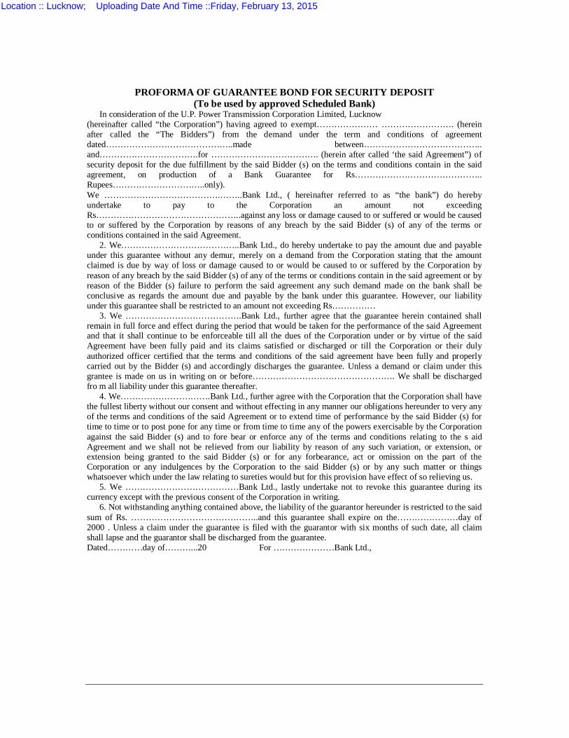
PROFORMA OF GUARANTEE BOND FOR SECURITY DEPOSIT (To be used by approved Scheduled Bank)
In consideration of the U.P. Power Transmission Corporation Limited, Lucknow (hereinafter called “the Corporation”) having agreed to exempt………………… ……………………. (herein after called the “The Bidders”) from the demand under the term and conditions of agreement dated……………………………………..made between………………………………….. and…………………………….for ………………………………. (herein after called ‘the said Agreement”) of security deposit for the due fulfillment by the said Bidder (s) on the terms and conditions contain in the said agreement, on production of a Bank Guarantee for Rs…………………………………….. Rupees…………………………..only). We ………………………………….……..Bank Ltd., ( hereinafter referred to as “the bank”) do hereby undertake to pay to the Corporation an amount not exceeding Rs…………………………………………..against any loss or damage caused to or suffered or would be caused to or suffered by the Corporation by reasons of any breach by the said Bidder (s) of any of the terms or conditions contained in the said Agreement.
2. We…………………………………..Bank Ltd., do hereby undertake to pay the amount due and payable under this guarantee without any demur, merely on a demand from the Corporation stating that the amount claimed is due by way of loss or damage caused to or would be caused to or suffered by the Corporation by reason of any breach by the said Bidder (s) of any of the terms or conditions contain in the said agreement or by reason of the Bidder (s) failure to perform the said agreement any such demand made on the bank shall be conclusive as regards the amount due and payable by the bank under this guarantee. However, our liability under this guarantee shall be restricted to an amount not exceeding Rs……………
3. We ………………………………….Bank Ltd., further agree that the guarantee herein contained shall remain in full force and effect during the period that would be taken for the performance of the said Agreement and that it shall continue to be enforceable till all the dues of the Corporation under or by virtue of the said Agreement have been fully paid and its claims satisfied or discharged or till the Corporation or their duly authorized officer certified that the terms and conditions of the said agreement have been fully and properly carried out by the Bidder (s) and accordingly discharges the guarantee. Unless a demand or claim under this grantee is made on us in writing on or before…………………………………………. We shall be discharged fro m all liability under this guarantee thereafter.
4. We………………………….Bank Ltd., further agree with the Corporation that the Corporation shall have the fullest liberty without our consent and without effecting in any manner our obligations hereunder to very any of the terms and conditions of the said Agreement or to extend time of performance by the said Bidder (s) for time to time or to post pone for any time or from time to time any of the powers exercisable by the Corporation against the said Bidder (s) and to fore bear or enforce any of the terms and conditions relating to the s aid Agreement and we shall not be relieved from our liability by reason of any such variation, or extension, or extension being granted to the said Bidder (s) or for any forbearance, act or omission on the part of the Corporation or any indulgences by the Corporation to the said Bidder (s) or by any such matter or things whatsoever which under the law relating to sureties would but for this provision have effect of so relieving us.
5. We …………………………………Bank Ltd., lastly undertake not to revoke this guarantee during its currency except with the previous consent of the Corporation in writing.
6. Not withstanding anything contained above, the liability of the guarantor hereunder is restricted to the said sum of Rs. ……………………………………..and this guarantee shall expire on the…………………day of 2000 . Unless a claim under the guarantee is filed with the guarantor with six months of such date, all claim shall lapse and the guarantor shall be discharged from the guarantee. Dated…………day of………...20 For …………………Bank Ltd.,
Location :: Lucknow; Uploading Date And Time ::Friday, February 13, 2015
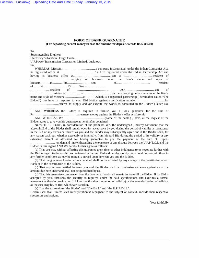
FORM OF BANK GUARNATEE (For depositing earnest money in case the amount for deposit exceeds Rs.5,000.00)
To, Superintending Engineer Electricity Substation Design Circle-II U.P.Power Transmission Corporation Limited, Lucknow. Sir,
WHEREAS, Messers…………………………….a company incorporated under the Indian Companies Act, its registered office at ……………………………./ a firm registered under the Indian Partnership Act and having its business office at………………………………..son of ………………………..resident of ………………………………….carrying on business under the firm’s name and style of Messers………at………../Sri……………………son of…………………………… resident of……..at……………………./Sri ……Son of……………… ………………..resident of ……………………………………../Sri………………………..son of ………………….resident of……………of……………………… partners carrying on business under the firm’s name and style of Messers ………………at………..which is a registered partnership ( hereinafter called “The Bidder”) has have in response to your Bid Notice against specification number ………………………for ……………………….offered to supply and /or execute the works as contained in the Bidder’s letter No. ……………………
AND WHEREAS the Bidder is required to furnish you a Bank guarantee for the sum of Rs…………………………………….as earnest money against the Bidder’s offer as aforesaid:
AND WHEREAS We ………………………………….(name of the bank ) , have, at the request of the Bidder agree to give you his guarantee as hereinafter contained:
NOW THEREFORE, in consideration of the promises We, the undersigned , hereby convenant that the aforesaid Bid of the Bidder shall remain open for acceptance by you during the period of validity as mentioned in the Bid or any extension thereof as you and the Bidder may subsequently agree and if the Bidder shall, for any reason back out, whether expressly or impliedly, from his said Bid during the period of its validity or any extension thereof as aforesaid we hereby guarantee to you the payment of the sum of Rupees ……………………..on demand , notwithstanding the existence of any dispute between the U.P.P.T.C.L and the Bidder in this regard AND We hereby further agree as follows:
(a) That you may without affecting this guarantee grant time or other indulgence to or negotiate further with the Bid in regard to the conditions contained in the said Bid and hereby modify these conditions or add there to any further conditions as may be mutually agreed upon between you and the Bidder.
(b) That the guarantee herein before contained shall not be affected by any change in the constitution of our Bank or in the constitution of the Bidder.
(c) That any account settled between you and the Bidder shall be conclusive evidence against us of the amount due here under and shall not be questioned by us.
(d) That this guarantee commencer from the date hereof and shall remain in force till the Bidder, If his Bid is accepted by you, furnishes the security as required under the said specifications and executes a formal agreement as therein provided or (till four months after the period of validity) or the extended period of validity, as the case may be, of Bid, whichever is earlier.
(e) That the expressions “the Bidder” and “The Bank” and “the U.P.P.T.C.L”. Herein used shall, unless such inter-pretation is repugnant to the subject or context, include their respective successors and assigns.
Your faithfully
Location :: Lucknow; Uploading Date And Time ::Friday, February 13, 2015

APPENDIX A
APPLICATION PROFORMA
Location :: Lucknow; Uploading Date And Time ::Friday, February 13, 2015
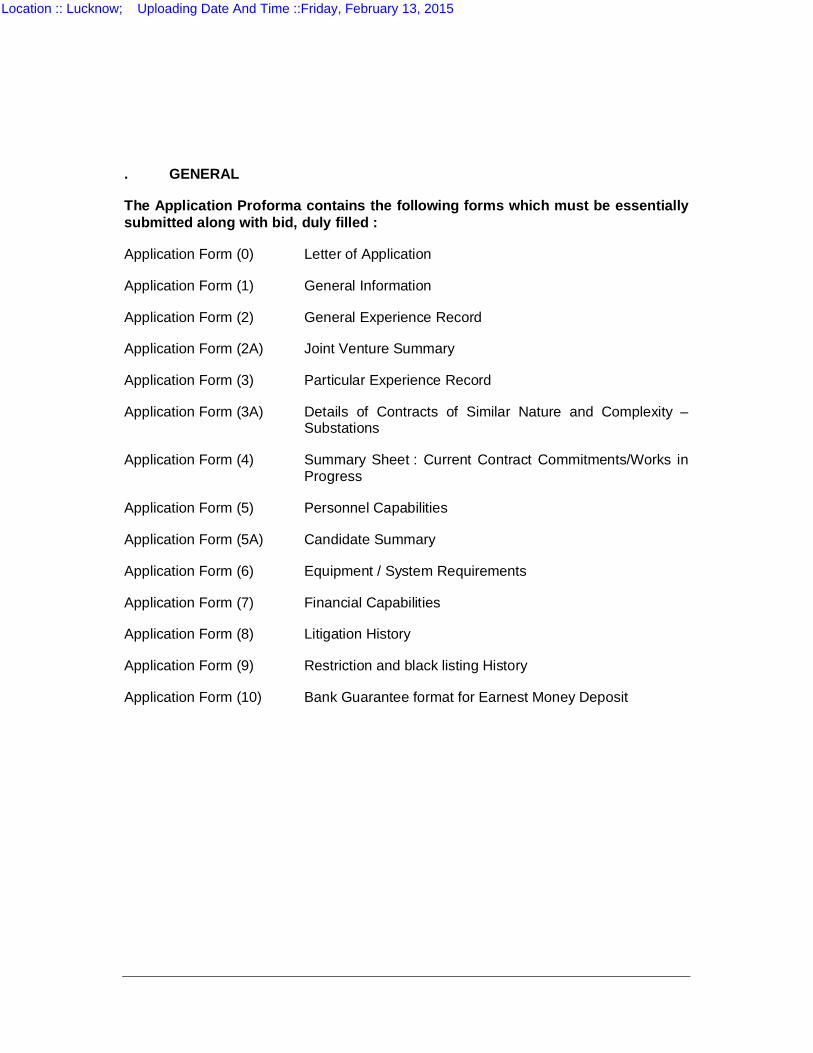
. GENERAL
The Application Proforma contains the following forms which must be essentially submitted along with bid, duly filled :
Application Form (0) Letter of Application
Application Form (1) General Information
Application Form (2) General Experience Record
Application Form (2A) Joint Venture Summary
Application Form (3) Particular Experience Record
Application Form (3A) Details of Contracts of Similar Nature and Complexity – Substations
Application Form (4) Summary Sheet : Current Contract Commitments/Works in Progress
Application Form (5) Personnel Capabilities
Application Form (5A) Candidate Summary
Application Form (6) Equipment / System Requirements
Application Form (7) Financial Capabilities
Application Form (8) Litigation History
Application Form (9) Restriction and black listing History
Application Form (10) Bank Guarantee format for Earnest Money Deposit
Location :: Lucknow; Uploading Date And Time ::Friday, February 13, 2015

APPENDIX A
APPLICATION FORM (0)
LETTER OF APPLICATION
Location :: Lucknow; Uploading Date And Time ::Friday, February 13, 2015
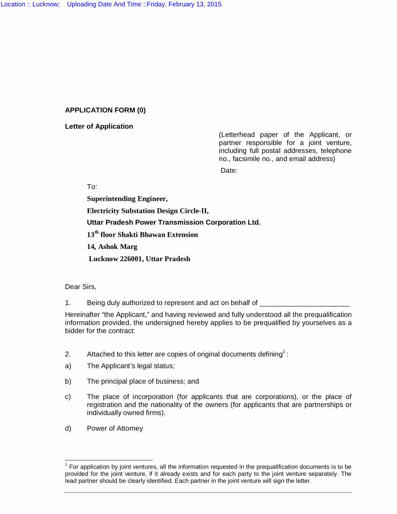
APPLICATION FORM (0) Letter of Application
(Letterhead paper of the Applicant, or partner responsible for a joint venture, including full postal addresses, telephone no., facsimile no., and email address) Date:
To:
Superintending Engineer,
Electricity Substation Design Circle-II, Uttar Pradesh Power Transmission Corporation Ltd.
13th floor Shakti Bhawan Extension 14, Ashok Marg
Lucknow 226001, Uttar Pradesh
Dear Sirs, 1. Being duly authorized to represent and act on behalf of _______________________
Hereinafter “the Applicant,” and having reviewed and fully understood all the prequalification information provided, the undersigned hereby applies to be prequalified by yourselves as a bidder for the contract:
2. Attached to this letter are copies of original documents defining1 : a) The Applicant’s legal status;
b) The principal place of business; and
c) The place of incorporation (for applicants that are corporations), or the place of registration and the nationality of the owners (for applicants that are partnerships or individually owned firms).
d) Power of Attorney
1 For application by joint ventures, all the information requested in the prequalification documents is to be provided for the joint venture, if it already exists and for each party to the joint venture separately. The lead partner should be clearly identified. Each partner in the joint venture will sign the letter.
Location :: Lucknow; Uploading Date And Time ::Friday, February 13, 2015
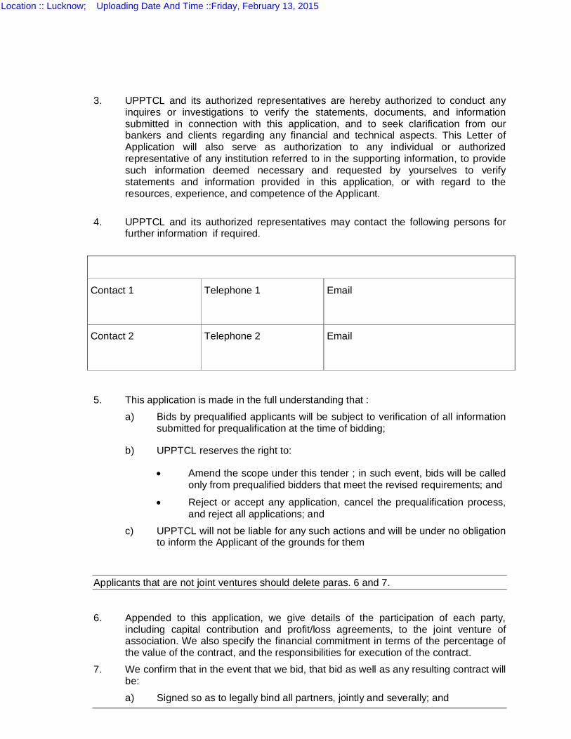
3. UPPTCL and its authorized representatives are hereby authorized to conduct any inquires or investigations to verify the statements, documents, and information submitted in connection with this application, and to seek clarification from our bankers and clients regarding any financial and technical aspects. This Letter of Application will also serve as authorization to any individual or authorized representative of any institution referred to in the supporting information, to provide such information deemed necessary and requested by yourselves to verify statements and information provided in this application, or with regard to the resources, experience, and competence of the Applicant.
4. UPPTCL and its authorized representatives may contact the following persons for
further information if required.
Contact 1
Telephone 1 Email
Contact 2
Telephone 2 Email
5. This application is made in the full understanding that :
a) Bids by prequalified applicants will be subject to verification of all information submitted for prequalification at the time of bidding;
b) UPPTCL reserves the right to:
Amend the scope under this tender ; in such event, bids will be called only from prequalified bidders that meet the revised requirements; and
Reject or accept any application, cancel the prequalification process, and reject all applications; and
c) UPPTCL will not be liable for any such actions and will be under no obligation to inform the Applicant of the grounds for them
Applicants that are not joint ventures should delete paras. 6 and 7.
6. Appended to this application, we give details of the participation of each party,
including capital contribution and profit/loss agreements, to the joint venture of association. We also specify the financial commitment in terms of the percentage of the value of the contract, and the responsibilities for execution of the contract.
7. We confirm that in the event that we bid, that bid as well as any resulting contract will be: a) Signed so as to legally bind all partners, jointly and severally; and
Location :: Lucknow; Uploading Date And Time ::Friday, February 13, 2015

b) Submitted with a joint venture agreement providing the joint and several liabilities of all partners in the event the contract is awarded to us.
Location :: Lucknow; Uploading Date And Time ::Friday, February 13, 2015
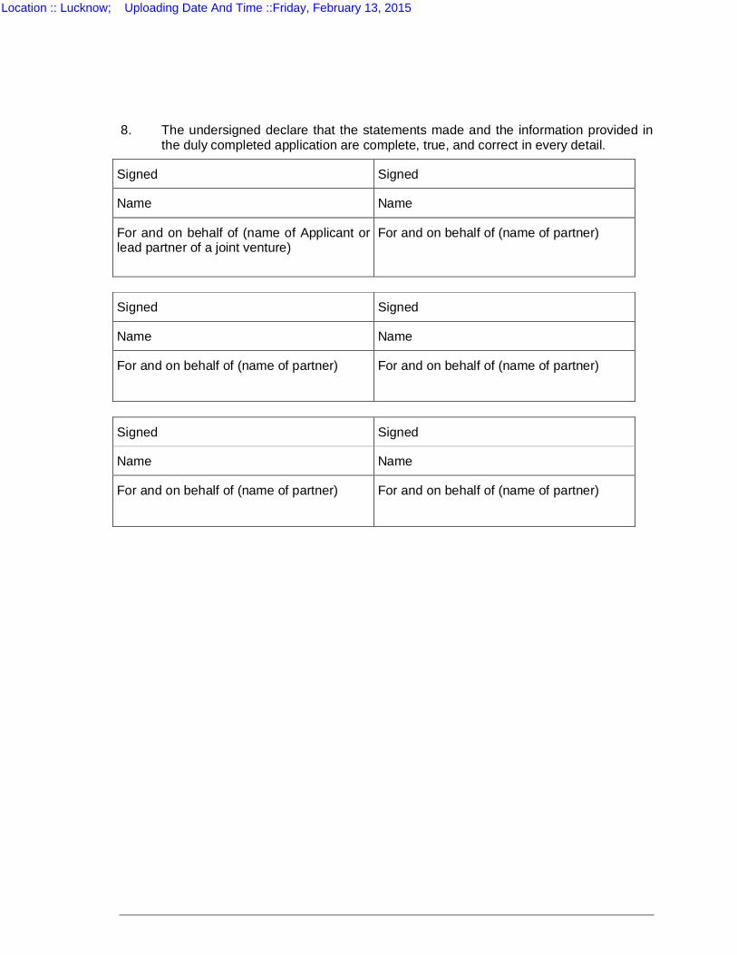
8. The undersigned declare that the statements made and the information provided in the duly completed application are complete, true, and correct in every detail.
Signed Signed
Name Name
For and on behalf of (name of Applicant or lead partner of a joint venture)
For and on behalf of (name of partner)
Signed Signed
Name Name
For and on behalf of (name of partner)
For and on behalf of (name of partner)
Signed Signed
Name Name
For and on behalf of (name of partner)
For and on behalf of (name of partner)
Location :: Lucknow; Uploading Date And Time ::Friday, February 13, 2015

APPENDIX A
APPLICATION FORM (1)
GENERAL INFORMATION
Location :: Lucknow; Uploading Date And Time ::Friday, February 13, 2015
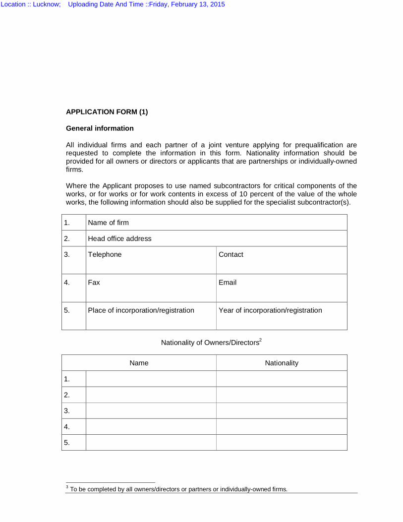
APPLICATION FORM (1) General information All individual firms and each partner of a joint venture applying for prequalification are requested to complete the information in this form. Nationality information should be provided for all owners or directors or applicants that are partnerships or individually-owned firms. Where the Applicant proposes to use named subcontractors for critical components of the works, or for works or for work contents in excess of 10 percent of the value of the whole works, the following information should also be supplied for the specialist subcontractor(s).
1. Name of firm
2. Head office address
3. Telephone
Contact
4. Fax
5. Place of incorporation/registration
Year of incorporation/registration
Nationality of Owners/Directors2
Name Nationality
1.
2.
3.
4.
5.
3 To be completed by all owners/directors or partners or individually-owned firms.
Location :: Lucknow; Uploading Date And Time ::Friday, February 13, 2015

APPENDIX A
APPLICATION FORM (2)
GENERAL EXPERIENCE RECORD
Location :: Lucknow; Uploading Date And Time ::Friday, February 13, 2015
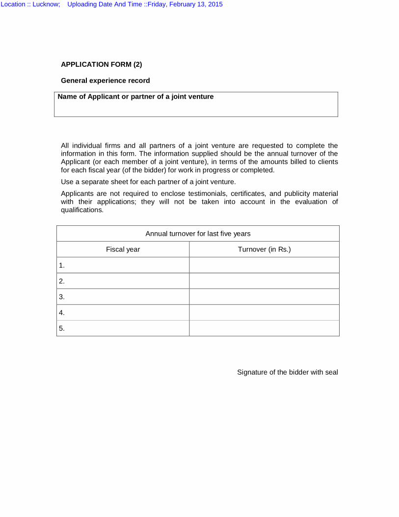
APPLICATION FORM (2) General experience record
Name of Applicant or partner of a joint venture All individual firms and all partners of a joint venture are requested to complete the information in this form. The information supplied should be the annual turnover of the Applicant (or each member of a joint venture), in terms of the amounts billed to clients for each fiscal year (of the bidder) for work in progress or completed. Use a separate sheet for each partner of a joint venture. Applicants are not required to enclose testimonials, certificates, and publicity material with their applications; they will not be taken into account in the evaluation of qualifications.
Annual turnover for last five years
Fiscal year Turnover (in Rs.)
1.
2.
3.
4.
5.
Signature of the bidder with seal
Location :: Lucknow; Uploading Date And Time ::Friday, February 13, 2015
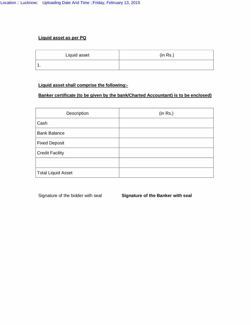
Liquid asset as per PQ
Liquid asset (in Rs.)
1.
Liquid asset shall comprise the following:- Banker certificate (to be given by the bank/Charted Accountant) is to be enclosed)
Description (in Rs.)
Cash
Bank Balance
Fixed Deposit
Credit Facility
Total Liquid Asset
Signature of the bidder with seal Signature of the Banker with seal
Location :: Lucknow; Uploading Date And Time ::Friday, February 13, 2015

APPENDIX A
APPLICATION FORM (2A)
JOINT VENTURE SUMMARY
Location :: Lucknow; Uploading Date And Time ::Friday, February 13, 2015
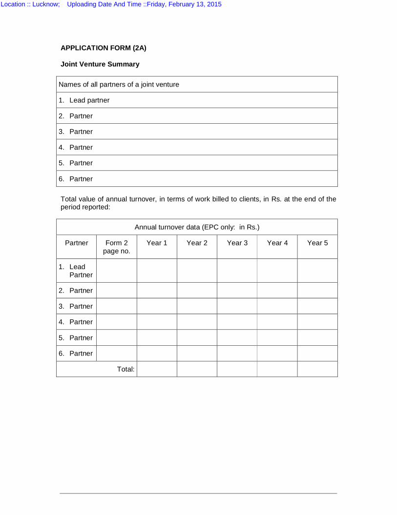
APPLICATION FORM (2A) Joint Venture Summary
Names of all partners of a joint venture
1. Lead partner
2. Partner
3. Partner
4. Partner
5. Partner
6. Partner
Total value of annual turnover, in terms of work billed to clients, in Rs. at the end of the period reported:
Annual turnover data (EPC only: in Rs.)
Partner Form 2 page no.
Year 1 Year 2 Year 3 Year 4 Year 5
1. Lead Partner
2. Partner
3. Partner
4. Partner
5. Partner
6. Partner
Total:
Location :: Lucknow; Uploading Date And Time ::Friday, February 13, 2015

APPENDIX A
APPLICATION FORM (3)
PARTICULAR EXPERIENCE RECORD
Location :: Lucknow; Uploading Date And Time ::Friday, February 13, 2015
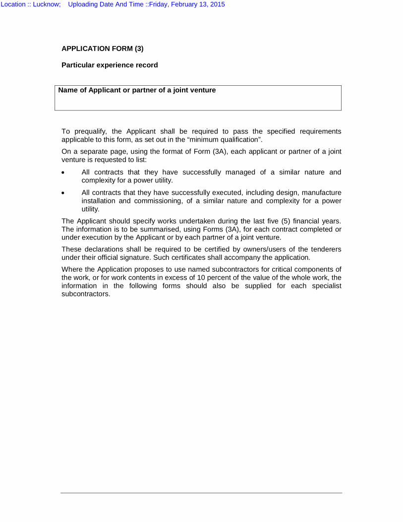
APPLICATION FORM (3) Particular experience record
Name of Applicant or partner of a joint venture To prequalify, the Applicant shall be required to pass the specified requirements applicable to this form, as set out in the “minimum qualification”. On a separate page, using the format of Form (3A), each applicant or partner of a joint venture is requested to list:
All contracts that they have successfully managed of a similar nature and complexity for a power utility.
All contracts that they have successfully executed, including design, manufacture installation and commissioning, of a similar nature and complexity for a power utility.
The Applicant should specify works undertaken during the last five (5) financial years. The information is to be summarised, using Forms (3A), for each contract completed or under execution by the Applicant or by each partner of a joint venture. These declarations shall be required to be certified by owners/users of the tenderers under their official signature. Such certificates shall accompany the application. Where the Application proposes to use named subcontractors for critical components of the work, or for work contents in excess of 10 percent of the value of the whole work, the information in the following forms should also be supplied for each specialist subcontractors.
Location :: Lucknow; Uploading Date And Time ::Friday, February 13, 2015

APPENDIX A
APPLICATION FORMS (3A )
DETAILS OF CONTRACTS OF SIMILAR NATURE AND COMPLEXITY
Location :: Lucknow; Uploading Date And Time ::Friday, February 13, 2015
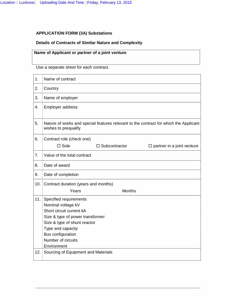
APPLICATION FORM (3A) Substations Details of Contracts of Similar Nature and Complexity
Name of Applicant or partner of a joint venture Use a separate sheet for each contract.
1. Name of contract
2. Country
3. Name of employer
4. Employer address
5. Nature of works and special features relevant to the contract for which the Applicant wishes to prequalify
6. Contract role (check one) Sole Subcontractor partner in a joint venture
7. Value of the total contract
8. Date of award
9. Date of completion
10. Contract duration (years and months) Years Months
11. Specified requirements Nominal voltage kV Short circuit current kA Size & type of power transformer Size & type of shunt reactor Type and capacity Bus configuration Number of circuits Environment 12. Sourcing of Equipment and Materials
Location :: Lucknow; Uploading Date And Time ::Friday, February 13, 2015

APPENDIX A
APPLICATION FORM (4)
SUMMARY SHEET: CURRENT CONTRACT COMMITMENTS/WORKS IN PROGRESS
Location :: Lucknow; Uploading Date And Time ::Friday, February 13, 2015
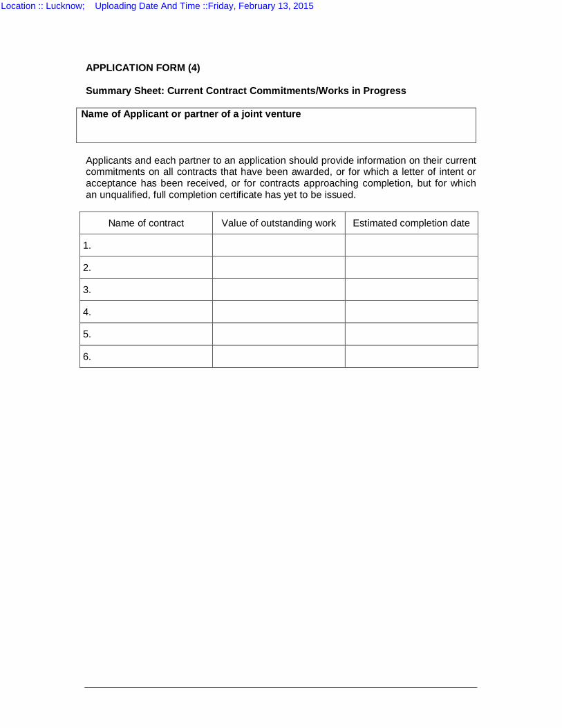
APPLICATION FORM (4) Summary Sheet: Current Contract Commitments/Works in Progress
Name of Applicant or partner of a joint venture Applicants and each partner to an application should provide information on their current commitments on all contracts that have been awarded, or for which a letter of intent or acceptance has been received, or for contracts approaching completion, but for which an unqualified, full completion certificate has yet to be issued.
Name of contract Value of outstanding work Estimated completion date
1.
2.
3.
4.
5.
6.
Location :: Lucknow; Uploading Date And Time ::Friday, February 13, 2015

APPENDIX A
APPLICATION FORM (5)
PERSONNEL CAPABILITIES
Location :: Lucknow; Uploading Date And Time ::Friday, February 13, 2015
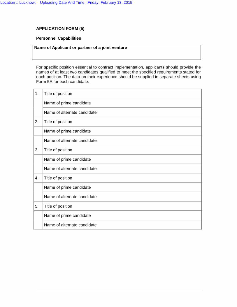
APPLICATION FORM (5) Personnel Capabilities
Name of Applicant or partner of a joint venture For specific position essential to contract implementation, applicants should provide the names of at least two candidates qualified to meet the specified requirements stated for each position. The data on their experience should be supplied in separate sheets using Form 5A for each candidate.
1. Title of position
Name of prime candidate
Name of alternate candidate
2. Title of position
Name of prime candidate
Name of alternate candidate
3. Title of position
Name of prime candidate
Name of alternate candidate
4. Title of position
Name of prime candidate
Name of alternate candidate
5. Title of position
Name of prime candidate
Name of alternate candidate
Location :: Lucknow; Uploading Date And Time ::Friday, February 13, 2015

APPENDIX A
APPLICATION FORM (5A)
CANDIDATE SUMMARY
Location :: Lucknow; Uploading Date And Time ::Friday, February 13, 2015
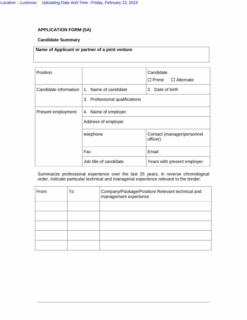
APPLICATION FORM (5A) Candidate Summary
Name of Applicant or partner of a joint venture
Position Candidate
Prime Alternate
Candidate information 1. Name of candidate 2. Date of birth
3. Professional qualifications
Present employment 4. Name of employer
Address of employer
telephone Contact (manager/personnel officer)
Fax Email
Job title of candidate Years with present employer
Summarize professional experience over the last 25 years, in reverse chronological order. Indicate particular technical and managerial experience relevant to the tender.
From To Company/Package/Position/ Relevant technical and management experience
Location :: Lucknow; Uploading Date And Time ::Friday, February 13, 2015

APPENDIX A
APPLICATION FORM (6)
EQUIPMENT / SYSTEM CAPABILITIES
Location :: Lucknow; Uploading Date And Time ::Friday, February 13, 2015
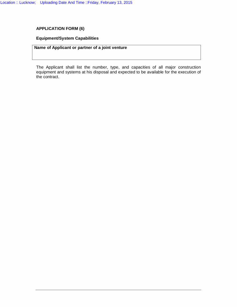
APPLICATION FORM (6) Equipment/System Capabilities
Name of Applicant or partner of a joint venture The Applicant shall list the number, type, and capacities of all major construction equipment and systems at his disposal and expected to be available for the execution of the contract.
Location :: Lucknow; Uploading Date And Time ::Friday, February 13, 2015

APPENDIX A
APPLICATION FORM (7)
FINANCIAL CAPABILITIES
Location :: Lucknow; Uploading Date And Time ::Friday, February 13, 2015
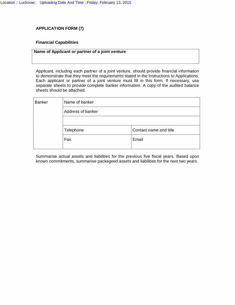
APPLICATION FORM (7)
Financial Capabilities
Name of Applicant or partner of a joint venture Applicant, including each partner of a joint venture, should provide financial information to demonstrate that they meet the requirements stated in the Instructions to Applications. Each applicant or partner of a joint venture must fill in this form. If necessary, use separate sheets to provide complete banker information. A copy of the audited balance sheets should be attached.
Banker Name of banker
Address of banker
Telephone Contact name and title
Fax
Summarise actual assets and liabilities for the previous five fiscal years. Based upon known commitments, summarise packageed assets and liabilities for the next two years.
Location :: Lucknow; Uploading Date And Time ::Friday, February 13, 2015
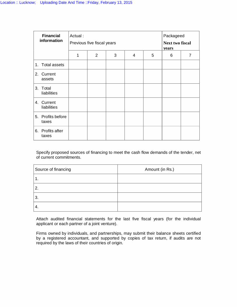
Financial information
Actual :
Previous five fiscal years
Packageed
Next two fiscal years
1 2 3 4 5 6 7
1. Total assets
2. Current assets
3. Total liabilities
4. Current liabilities
5. Profits before taxes
6. Profits after taxes
Specify proposed sources of financing to meet the cash flow demands of the tender, net of current commitments.
Source of financing Amount (in Rs.)
1.
2.
3.
4.
Attach audited financial statements for the last five fiscal years (for the individual applicant or each partner of a joint venture). Firms owned by individuals, and partnerships, may submit their balance sheets certified by a registered accountant, and supported by copies of tax return, if audits are not required by the laws of their countries of origin.
Location :: Lucknow; Uploading Date And Time ::Friday, February 13, 2015

APPENDIX A APPLICATION FORM (8)
LITIGATION HISTORY
Location :: Lucknow; Uploading Date And Time ::Friday, February 13, 2015

Location :: Lucknow; Uploading Date And Time ::Friday, February 13, 2015
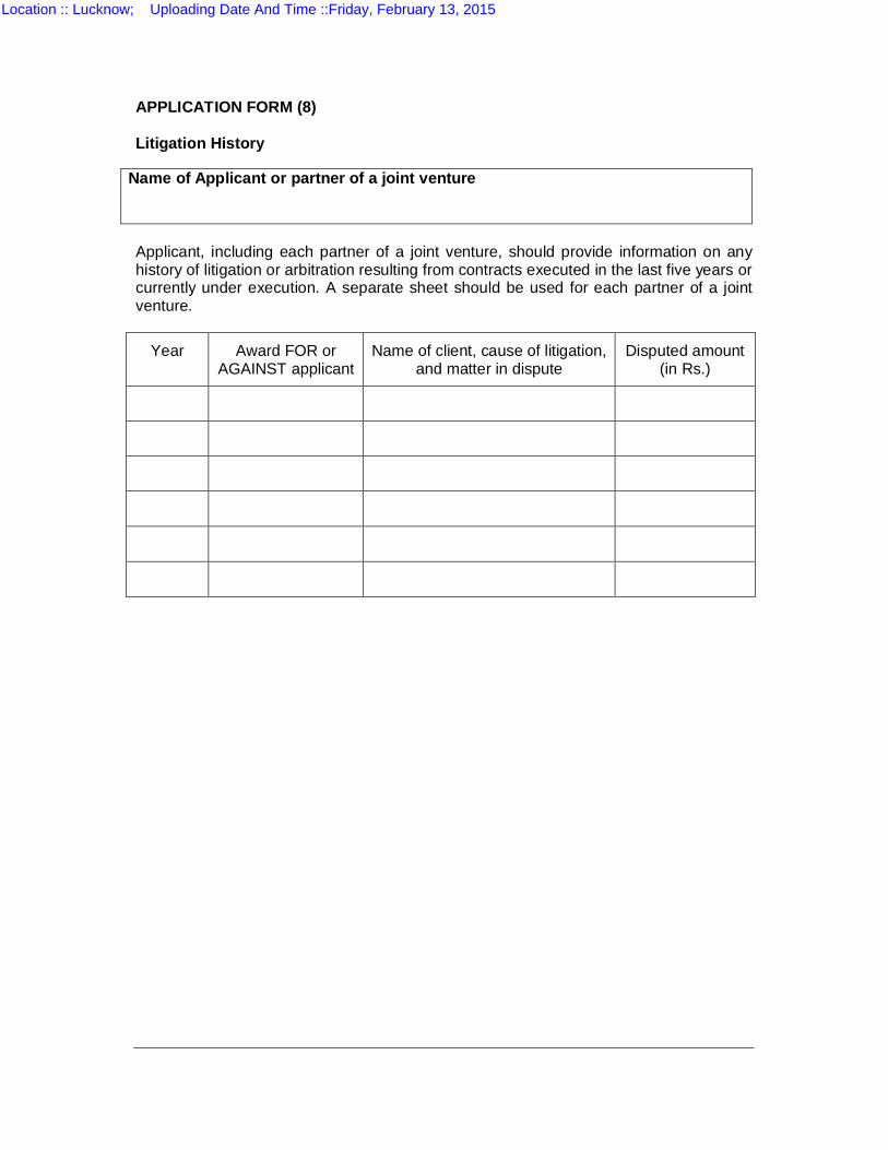
APPLICATION FORM (8) Litigation History
Name of Applicant or partner of a joint venture Applicant, including each partner of a joint venture, should provide information on any history of litigation or arbitration resulting from contracts executed in the last five years or currently under execution. A separate sheet should be used for each partner of a joint venture.
Year Award FOR or AGAINST applicant
Name of client, cause of litigation, and matter in dispute
Disputed amount (in Rs.)
Location :: Lucknow; Uploading Date And Time ::Friday, February 13, 2015

APPENDIX A
APPLICATION FORM (9)
RESTRICTION AND BLACK LISTING HISTORY
Location :: Lucknow; Uploading Date And Time ::Friday, February 13, 2015
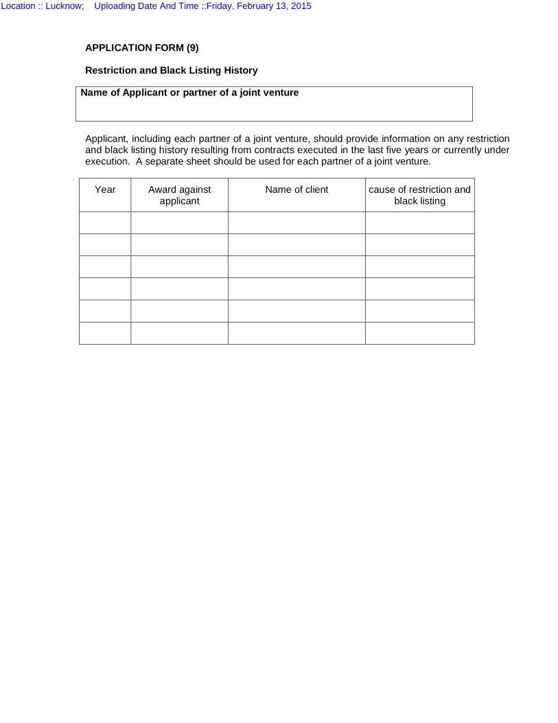
APPLICATION FORM (9) Restriction and Black Listing History
Name of Applicant or partner of a joint venture Applicant, including each partner of a joint venture, should provide information on any restriction and black listing history resulting from contracts executed in the last five years or currently under execution. A separate sheet should be used for each partner of a joint venture.
Year Award against applicant
Name of client cause of restriction and black listing
Location :: Lucknow; Uploading Date And Time ::Friday, February 13, 2015

APPLICATION FORM (10)
BANK GUARANTEE FORMAT FOR EARNEST MONEY DEPOSIT
Location :: Lucknow; Uploading Date And Time ::Friday, February 13, 2015
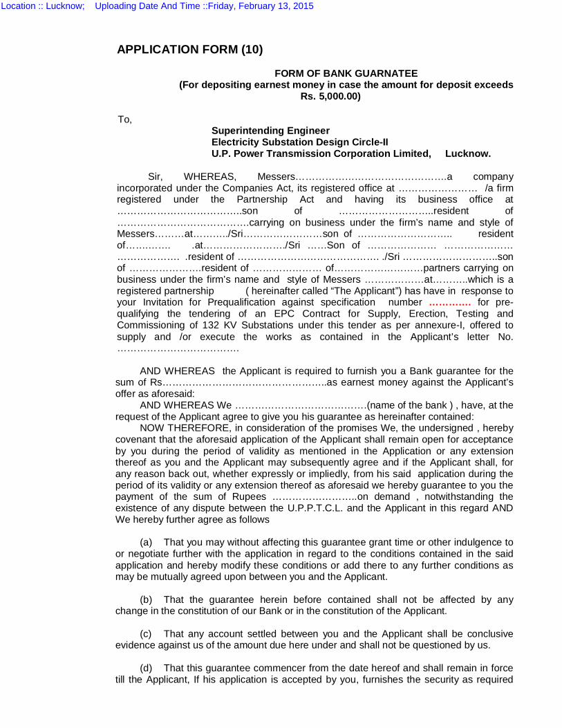
APPLICATION FORM (10)
FORM OF BANK GUARNATEE (For depositing earnest money in case the amount for deposit exceeds
Rs. 5,000.00)
To, Superintending Engineer Electricity Substation Design Circle-II U.P. Power Transmission Corporation Limited, Lucknow.
Sir, WHEREAS, Messers……………………………………….a company
incorporated under the Companies Act, its registered office at …………………… /a firm registered under the Partnership Act and having its business office at ………………………………..son of ………………………..resident of ………………………………….carrying on business under the firm’s name and style of Messers………at………../Sri……………………son of ……………………….. resident of…….……. .at……………………./Sri ……Son of ………………… ………………… ………………. .resident of ……………………………………. ./Sri ………………………..son of ………………….resident of ………………… of………………………partners carrying on business under the firm’s name and style of Messers ………………at………..which is a registered partnership ( hereinafter called “The Applicant”) has have in response to your Invitation for Prequalification against specification number …………. for pre-qualifying the tendering of an EPC Contract for Supply, Erection, Testing and Commissioning of 132 KV Substations under this tender as per annexure-I, offered to supply and /or execute the works as contained in the Applicant’s letter No. ……………………………….
AND WHEREAS the Applicant is required to furnish you a Bank guarantee for the
sum of Rs…………………………………………..as earnest money against the Applicant’s offer as aforesaid:
AND WHEREAS We ………………………………….(name of the bank ) , have, at the request of the Applicant agree to give you his guarantee as hereinafter contained:
NOW THEREFORE, in consideration of the promises We, the undersigned , hereby covenant that the aforesaid application of the Applicant shall remain open for acceptance by you during the period of validity as mentioned in the Application or any extension thereof as you and the Applicant may subsequently agree and if the Applicant shall, for any reason back out, whether expressly or impliedly, from his said application during the period of its validity or any extension thereof as aforesaid we hereby guarantee to you the payment of the sum of Rupees ……………………..on demand , notwithstanding the existence of any dispute between the U.P.P.T.C.L. and the Applicant in this regard AND We hereby further agree as follows
(a) That you may without affecting this guarantee grant time or other indulgence to
or negotiate further with the application in regard to the conditions contained in the said application and hereby modify these conditions or add there to any further conditions as may be mutually agreed upon between you and the Applicant.
(b) That the guarantee herein before contained shall not be affected by any
change in the constitution of our Bank or in the constitution of the Applicant. (c) That any account settled between you and the Applicant shall be conclusive
evidence against us of the amount due here under and shall not be questioned by us. (d) That this guarantee commencer from the date hereof and shall remain in force
till the Applicant, If his application is accepted by you, furnishes the security as required
Location :: Lucknow; Uploading Date And Time ::Friday, February 13, 2015

under the said specifications and executes a formal agreement as therein provided or (till four months after the period of validity) or the extended period of validity, as the case may be, of application, whichever is earlier.
(e) That the expressions “the Applicant” and “The Bank” and “the U.P.P.T.C.L”.
Herein used shall, unless such interpretation is repugnant to the subject or context, include their respective successors and assigns.
Yours faithfully
Location :: Lucknow; Uploading Date And Time ::Friday, February 13, 2015

APPENDIX B
BID SCHEDULES
Location :: Lucknow; Uploading Date And Time ::Friday, February 13, 2015
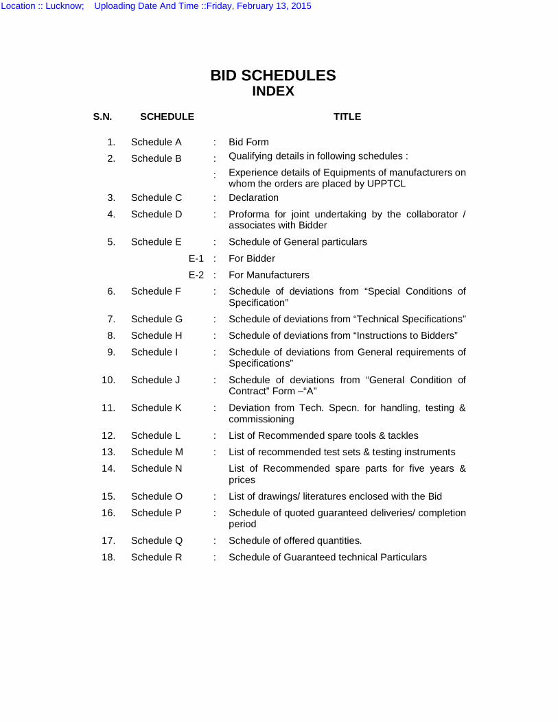
BID SCHEDULES INDEX
S.N. SCHEDULE TITLE
1. Schedule A : Bid Form 2. Schedule B : Qualifying details in following schedules :
: Experience details of Equipments of manufacturers on whom the orders are placed by UPPTCL
3. Schedule C : Declaration
4. Schedule D : Proforma for joint undertaking by the collaborator / associates with Bidder
5. Schedule E : Schedule of General particulars
E-1 : For Bidder E-2 : For Manufacturers
6. Schedule F : Schedule of deviations from “Special Conditions of Specification”
7. Schedule G : Schedule of deviations from “Technical Specifications” 8. Schedule H : Schedule of deviations from “Instructions to Bidders”
9. Schedule I : Schedule of deviations from General requirements of Specifications”
10. Schedule J : Schedule of deviations from “General Condition of Contract” Form –“A”
11. Schedule K : Deviation from Tech. Specn. for handling, testing & commissioning
12. Schedule L : List of Recommended spare tools & tackles 13. Schedule M : List of recommended test sets & testing instruments 14. Schedule N List of Recommended spare parts for five years &
prices
15. Schedule O : List of drawings/ literatures enclosed with the Bid 16. Schedule P : Schedule of quoted guaranteed deliveries/ completion
period
17. Schedule Q : Schedule of offered quantities.
18. Schedule R : Schedule of Guaranteed technical Particulars
Location :: Lucknow; Uploading Date And Time ::Friday, February 13, 2015
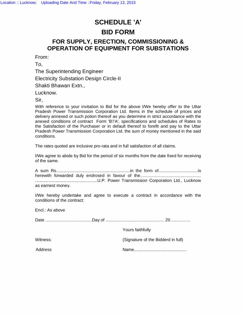
SCHEDULE 'A' BID FORM
FOR SUPPLY, ERECTION, COMMISSIONING & OPERATION OF EQUIPMENT FOR SUBSTATIONS
From: To, The Superintending Engineer Electricity Substation Design Circle-II Shakti Bhawan Extn., Lucknow. Sir, With reference to your invitation to Bid for the above I/We hereby offer to the Uttar Pradesh Power Transmission Corporation Ltd. Items in the schedule of prices and delivery annexed or such potion thereof as you determine in strict accordance with the anexed conditions of contract Form 'B'/'A', specifications and schedules of Rates to the Satisfaction of the Purchaser or in default thereof to forefit and pay to the Uttar Pradesh Power Transmission Corporation Ltd. the sum of money mentioned in the said conditions. The rates quoted are inclusive pro-rata and in full satisfaction of all claims. l/We agree to abide by Bid for the period of six months from the date fixed for receiving of the same. A sum Rs..............................................................in the form of.................................is herewith forwarded duly endrosed in favour of the................................................... ....................................................U.P. Power Transmission Corporation Ltd., Lucknow as earnest money. I/We hereby undertake and agree to execute a contract in accordance with the conditions of the contract: Encl.: As above Date .......................................Day of ................................................. 20 ................ Yours faithfully Witness: (Signature of the Bidderd in full) Address Name............................................
Location :: Lucknow; Uploading Date And Time ::Friday, February 13, 2015
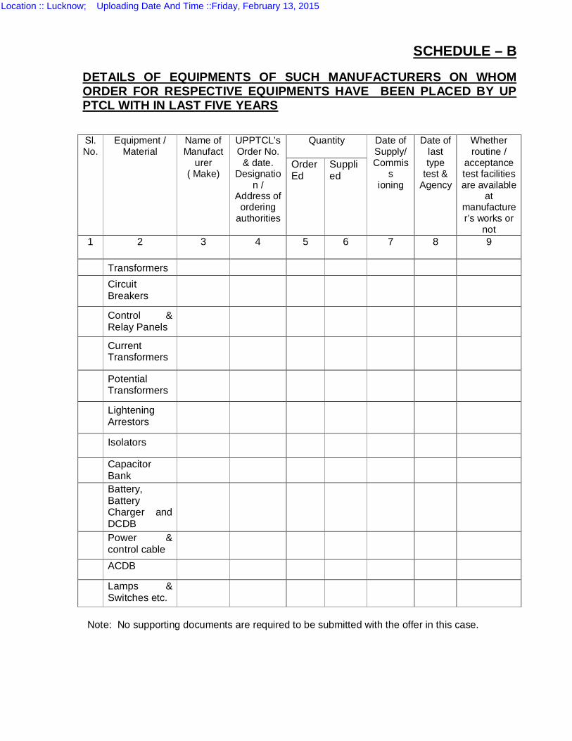
SCHEDULE – B
DETAILS OF EQUIPMENTS OF SUCH MANUFACTURERS ON WHOM ORDER FOR RESPECTIVE EQUIPMENTS HAVE BEEN PLACED BY UP PTCL WITH IN LAST FIVE YEARS
Sl. No.
Equipment / Material
Name of Manufact
urer ( Make)
UPPTCL’s Order No.
& date. Designatio
n / Address of
ordering authorities
Quantity
Date of Supply/ Commis
s ioning
Date of last type
test & Agency
Whether routine /
acceptance test facilities are available
at manufacturer’s works or
not
Order Ed
Suppli ed
1
2 3 4 5 6 7 8 9
Transformers
Circuit Breakers
Control & Relay Panels
Current Transformers
Potential Transformers
Lightening Arrestors
Isolators
Capacitor Bank
Battery, Battery Charger and DCDB
Power & control cable
ACDB
Lamps & Switches etc.
Note: No supporting documents are required to be submitted with the offer in this case.
Location :: Lucknow; Uploading Date And Time ::Friday, February 13, 2015
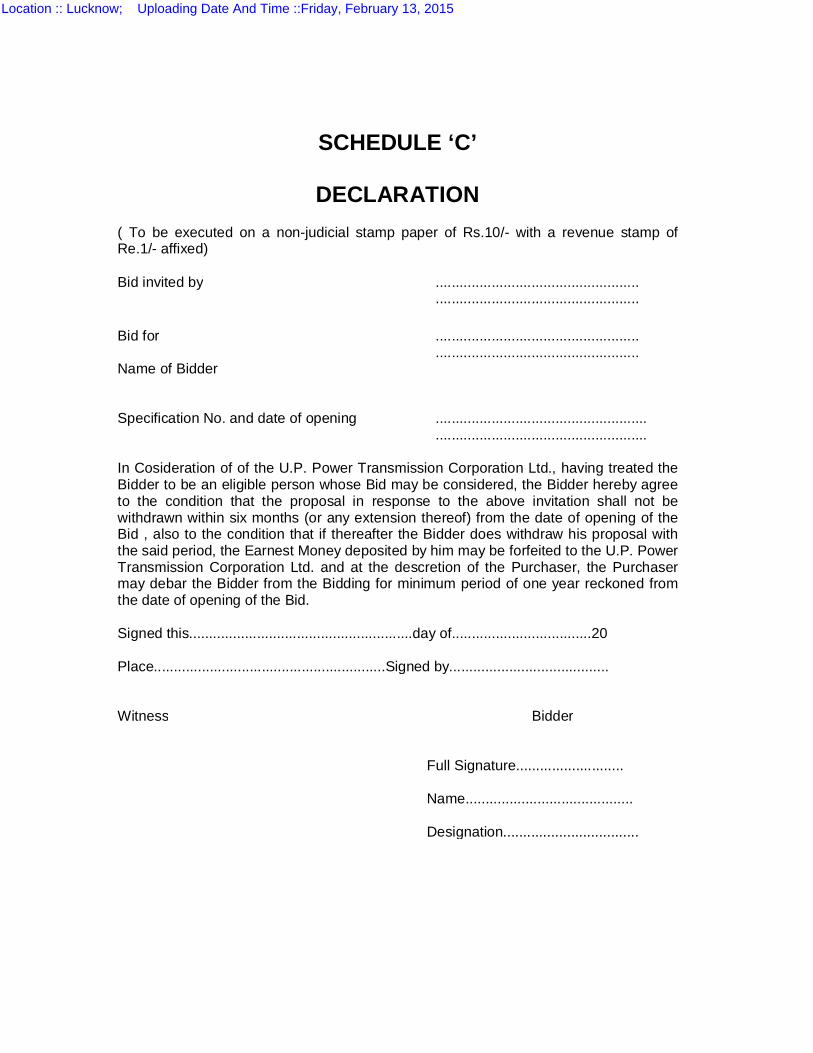
SCHEDULE ‘C’
DECLARATION ( To be executed on a non-judicial stamp paper of Rs.10/- with a revenue stamp of Re.1/- affixed) Bid invited by ................................................... ................................................... Bid for ................................................... ................................................... Name of Bidder Specification No. and date of opening ..................................................... ..................................................... In Cosideration of of the U.P. Power Transmission Corporation Ltd., having treated the Bidder to be an eligible person whose Bid may be considered, the Bidder hereby agree to the condition that the proposal in response to the above invitation shall not be withdrawn within six months (or any extension thereof) from the date of opening of the Bid , also to the condition that if thereafter the Bidder does withdraw his proposal with the said period, the Earnest Money deposited by him may be forfeited to the U.P. Power Transmission Corporation Ltd. and at the descretion of the Purchaser, the Purchaser may debar the Bidder from the Bidding for minimum period of one year reckoned from the date of opening of the Bid. Signed this........................................................day of...................................20 Place..........................................................Signed by........................................ Witness Bidder Full Signature........................... Name.......................................... Designation..................................
Location :: Lucknow; Uploading Date And Time ::Friday, February 13, 2015
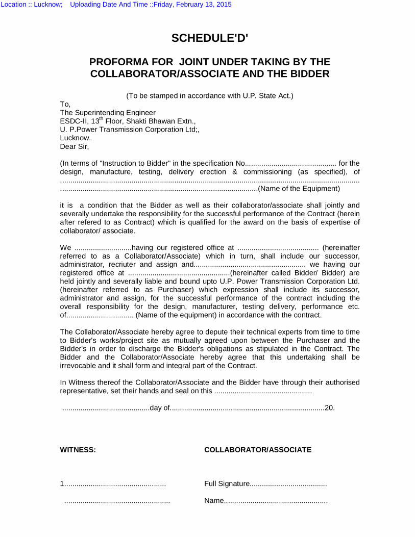
SCHEDULE'D'
PROFORMA FOR JOINT UNDER TAKING BY THE COLLABORATOR/ASSOCIATE AND THE BIDDER
(To be stamped in accordance with U.P. State Act.)
To, The Superintending Engineer ESDC-II, 13th Floor, Shakti Bhawan Extn., U. P.Power Transmission Corporation Ltd;, Lucknow. Dear Sir, (In terms of "Instruction to Bidder" in the specification No............................................. for the design, manufacture, testing, delivery erection & commissioning (as specified), of ................................................................................................................................................... .................................................................................................(Name of the Equipment) it is a condition that the Bidder as well as their collaborator/associate shall jointly and severally undertake the responsibility for the successful performance of the Contract (herein after refered to as Contract) which is qualified for the award on the basis of expertise of collaborator/ associate. We ............................having our registered office at ........................................ (hereinafter referred to as a Collaborator/Associate) which in turn, shall include our successor, administrator, recriuter and assign and....................................................... we having our registered office at ..................................................(hereinafter called Bidder/ Bidder) are held jointly and severally liable and bound upto U.P. Power Transmission Corporation Ltd. (hereinafter referred to as Purchaser) which expression shall include its successor, administrator and assign, for the successful performance of the contract including the overall responsibility for the design, manufacturer, testing delivery, performance etc. of................................. (Name of the equipment) in accordance with the contract. The Collaborator/Associate hereby agree to depute their technical experts from time to time to Bidder's works/project site as mutually agreed upon between the Purchaser and the Bidder's in order to discharge the Bidder's obligations as stipulated in the Contract. The Bidder and the Collaborator/Associate hereby agree that this undertaking shall be irrevocable and it shall form and integral part of the Contract. In Witness thereof the Collaborator/Associate and the Bidder have through their authorised representative, set their hands and seal on this ................................................ ...........................................day of............................................................................20. WITNESS: COLLABORATOR/ASSOCIATE
1.................................................. Full Signature...................................... .................................................... Name...................................................
Location :: Lucknow; Uploading Date And Time ::Friday, February 13, 2015
(Official Address) Designation.......................................... Seal Seal WITNESS: BIDDER 1.................................................. Full Signature...................................... .................................................... Name................................................... (Official Address) Designation........................................... Seal Seal
Location :: Lucknow; Uploading Date And Time ::Friday, February 13, 2015
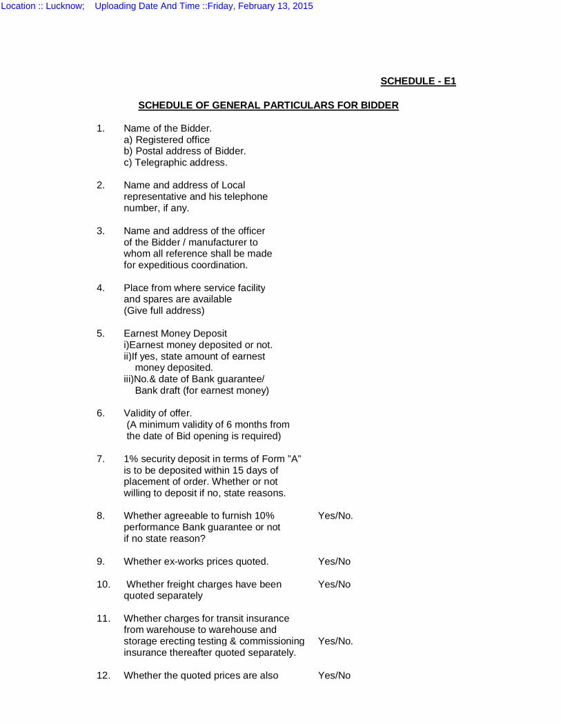
SCHEDULE - E1
SCHEDULE OF GENERAL PARTICULARS FOR BIDDER
1. Name of the Bidder.
a) Registered office b) Postal address of Bidder. c) Telegraphic address.
2. Name and address of Local representative and his telephone number, if any.
3. Name and address of the officer of the Bidder / manufacturer to whom all reference shall be made for expeditious coordination.
4. Place from where service facility and spares are available (Give full address)
5. Earnest Money Deposit i)Earnest money deposited or not. ii)If yes, state amount of earnest money deposited. iii)No.& date of Bank guarantee/ Bank draft (for earnest money)
6. Validity of offer. (A minimum validity of 6 months from the date of Bid opening is required)
7. 1% security deposit in terms of Form ”A” is to be deposited within 15 days of placement of order. Whether or not willing to deposit if no, state reasons.
8. Whether agreeable to furnish 10% Yes/No. performance Bank guarantee or not if no state reason?
9. Whether ex-works prices quoted. Yes/No
10. Whether freight charges have been Yes/No quoted separately
11. Whether charges for transit insurance from warehouse to warehouse and storage erecting testing & commissioning Yes/No. insurance thereafter quoted separately.
12. Whether the quoted prices are also Yes/No
Location :: Lucknow; Uploading Date And Time ::Friday, February 13, 2015
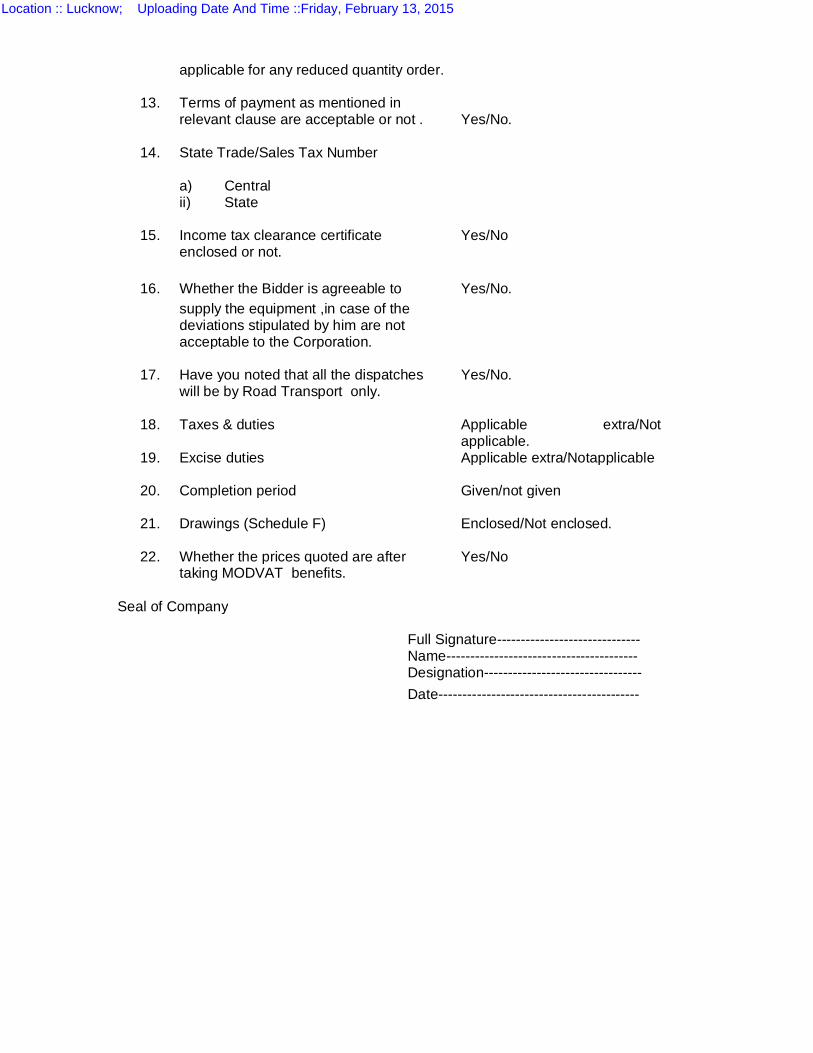
applicable for any reduced quantity order.
13. Terms of payment as mentioned in relevant clause are acceptable or not . Yes/No.
14. State Trade/Sales Tax Number a) Central ii) State
15. Income tax clearance certificate Yes/No enclosed or not.
16. Whether the Bidder is agreeable to Yes/No. supply the equipment ,in case of the deviations stipulated by him are not acceptable to the Corporation.
17. Have you noted that all the dispatches Yes/No. will be by Road Transport only.
18. Taxes & duties
Applicable extra/Not applicable.
19. Excise duties Applicable extra/Notapplicable
20. Completion period Given/not given
21. Drawings (Schedule F) Enclosed/Not enclosed.
22. Whether the prices quoted are after Yes/No taking MODVAT benefits.
Seal of Company Full Signature------------------------------ Name---------------------------------------- Designation--------------------------------- Date------------------------------------------
Location :: Lucknow; Uploading Date And Time ::Friday, February 13, 2015
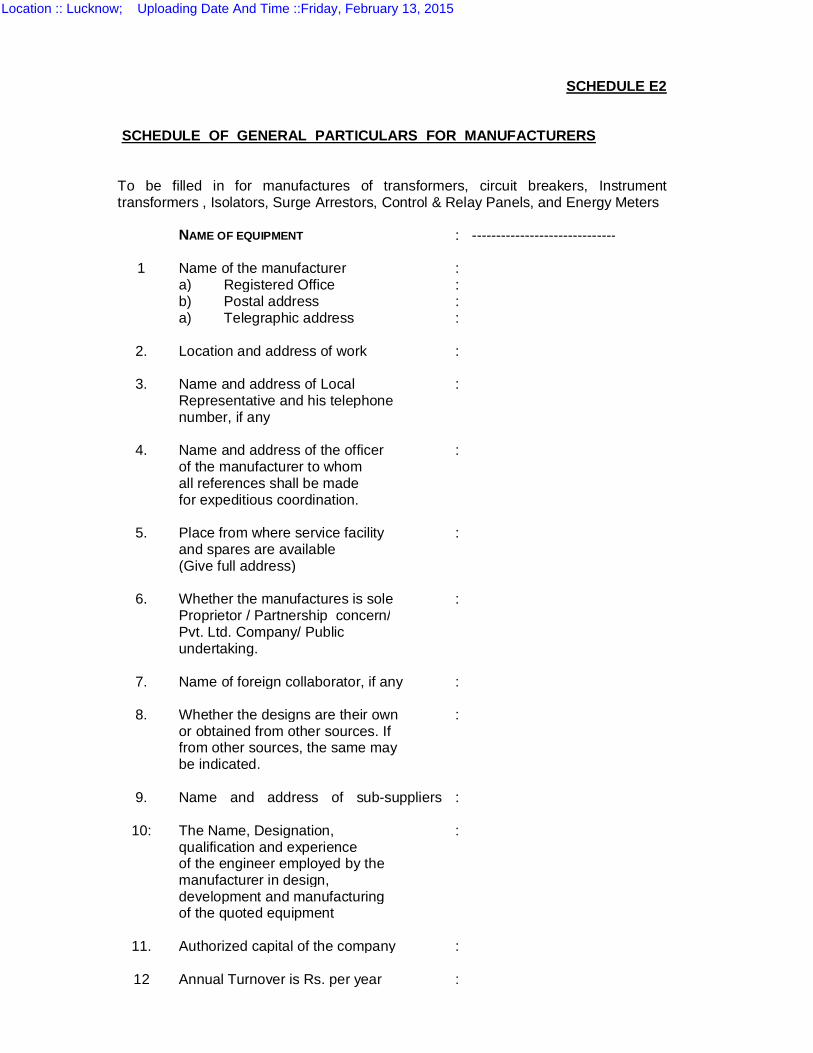
SCHEDULE E2
SCHEDULE OF GENERAL PARTICULARS FOR MANUFACTURERS To be filled in for manufactures of transformers, circuit breakers, Instrument transformers , Isolators, Surge Arrestors, Control & Relay Panels, and Energy Meters NAME OF EQUIPMENT : ------------------------------
1 Name of the manufacturer : a) Registered Office : b) Postal address : a) Telegraphic address :
2. Location and address of work :
3. Name and address of Local : Representative and his telephone number, if any
4. Name and address of the officer : of the manufacturer to whom all references shall be made for expeditious coordination.
5. Place from where service facility : and spares are available (Give full address)
6. Whether the manufactures is sole : Proprietor / Partnership concern/ Pvt. Ltd. Company/ Public undertaking.
7. Name of foreign collaborator, if any :
8. Whether the designs are their own : or obtained from other sources. If from other sources, the same may be indicated.
9. Name and address of sub-suppliers
:
10: The Name, Designation, : qualification and experience of the engineer employed by the manufacturer in design, development and manufacturing of the quoted equipment
11. Authorized capital of the company :
12 Annual Turnover is Rs. per year :
Location :: Lucknow; Uploading Date And Time ::Friday, February 13, 2015
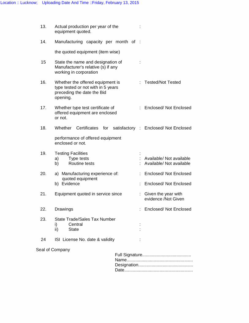
13. Actual production per year of the :
equipment quoted.
14. Manufacturing capacity per month of
:
the quoted equipment (item wise)
15 State the name and designation of : Manufacturer’s relative (s) if any working in corporation
16. Whether the offered equipment is : Tested/Not Tested type tested or not with in 5 years preceding the date the Bid opening.
17. Whether type test certificate of : Enclosed/ Not Enclosed offered equipment are enclosed or not.
18. Whether Certificates for satisfactory
: Enclosed/ Not Enclosed
performance of offered equipment enclosed or not.
19. Testing Facilities : a) Type tests : Available/ Not available b) Routine tests : Available/ Not available
20. a) Manufacturing experience of: : Enclosed/ Not Enclosed quoted equipment b) Evidence : Enclosed/ Not Enclosed
21. Equipment quoted in service since : Given the year with evidence /Not Given
22. Drawings : Enclosed/ Not Enclosed
23. State Trade/Sales Tax Number i) Central : ii) State :
24 ISI License No. date & validity : Seal of Company Full Signature........................................
Name...................................................... Designation............................................. Date........................................................
Location :: Lucknow; Uploading Date And Time ::Friday, February 13, 2015
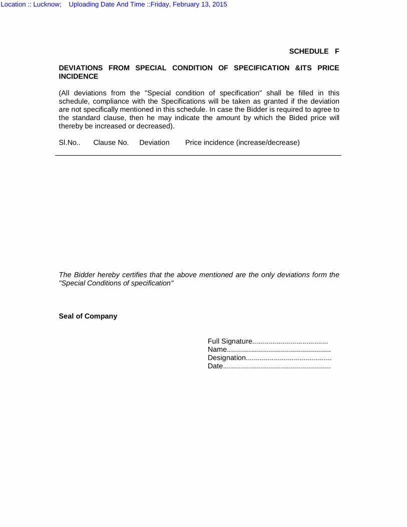
SCHEDULE F DEVIATIONS FROM SPECIAL CONDITION OF SPECIFICATION &ITS PRICE INCIDENCE (All deviations from the "Special condition of specification" shall be filled in this schedule, compliance with the Specifications will be taken as granted if the deviation are not specifically mentioned in this schedule. In case the Bidder is required to agree to the standard clause, then he may indicate the amount by which the Bided price will thereby be increased or decreased). Sl.No.. Clause No. Deviation Price incidence (increase/decrease) The Bidder hereby certifies that the above mentioned are the only deviations form the "Special Conditions of specification" Seal of Company Full Signature......................................
Name.................................................... Designation...........................................
Date......................................................
Location :: Lucknow; Uploading Date And Time ::Friday, February 13, 2015
SCHEDULE ‘G’
DEVIATIONS FROM ‘TECHNICAL SPECIFICATION’ & ITS PRICE INCIDENCE. (All deviations from the “Technical Specification” shall be filled in clause, in this schedule; compliance with the specification will be taken as granted if the deviation is not specifically mentioned in this schedule. In case the tenderer is required to agree to the standard clause, then he may indicate the amount by which the tenderered price will thereby be increased or decreased. Sl. No. Clause No. Deviation Price incidence (Increase/ Decrease) The Tenderer hereby certifies that the above mentioned are the only deviations from the ‘Technical Specification’. Seal of company Full Signature…………………….. Name …………………………….. Designation……………………….. Date…………………………………
Location :: Lucknow; Uploading Date And Time ::Friday, February 13, 2015
SCHEDULE 'H'
DEVIATIONS FROM "INSTRUCTIONS TO BIDDERS" & ITS PRICE INCIDENCE (All deviations from the "Instruction to Bidders" shall be filled in clause, in this schedule, compliance with the Specifications will be taken. as granted if the deviation are not specifically mentioned in this schedule. In case the Bidder is required to agree to the standard clause, then he may indicate the amount by which the Biddered price will thereby be increased or decreased).
SI. No.
Clause No. Deviation Price incidence (IncreaselDecrease)
The Bidder hereby certifies that the above mentioned are the only deviations from the "Instructions to Bidders" Seal of Company Full Signature ................................. Name............................................... Designation..................................... Date.................................................
Location :: Lucknow; Uploading Date And Time ::Friday, February 13, 2015
SCHEDULE - I
DEVIATIONS FROM GENERAL TECHNICAL REQUIREMENTS OF SPECIFICATION
&ITS PRICE INCIDENCE (All deviations from the General Technical Requirements Of Specification shall be filled in this schedule, compliance with the Specifications will be taken as granted if the deviation are not specifically mentioned in this schedule. In case the Bidder is required to agree to the standard clause, then he may indicate the amount by which the Bided price will thereby be increased or decreased). Sl.No. Clause
No. Deviation Price incidence (increase/decrease)
The Bidder hereby certifies that the above mentioned are the only deviations form the "General technical Requirements of specification" Seal of Company Full Signature...................................
Name................................................. Designation........................................
Date...................................................
Location :: Lucknow; Uploading Date And Time ::Friday, February 13, 2015
SCHEDULE 'J'
DEVIATIONS FROM "GENERAL CONDITIONS OF CONTRACT FORM A/B" & ITS PRICE INCIDENCE (All deviations from the "General Conditions of Contract Form A/B" shall be filled in clause, in this schedule, compliance with the Specifications will be taken as granted if the deviation are not specifically mentioned in this schedule. In case the Bidder is required to agree to the standard clause, then he may indicate the amount by which the Biddered price will thereby be increased or decreased). Sl.No. Clause No. Deviation Price incidence (Increase/Decrease)
The Bidder hereby certifies that the above mentioned are the only deviations from the "General conditions of Contract Form A/B". Seal of Company Full Signature......................................... Name...................................................... Designation............................................ Date.......................................................
Location :: Lucknow; Uploading Date And Time ::Friday, February 13, 2015
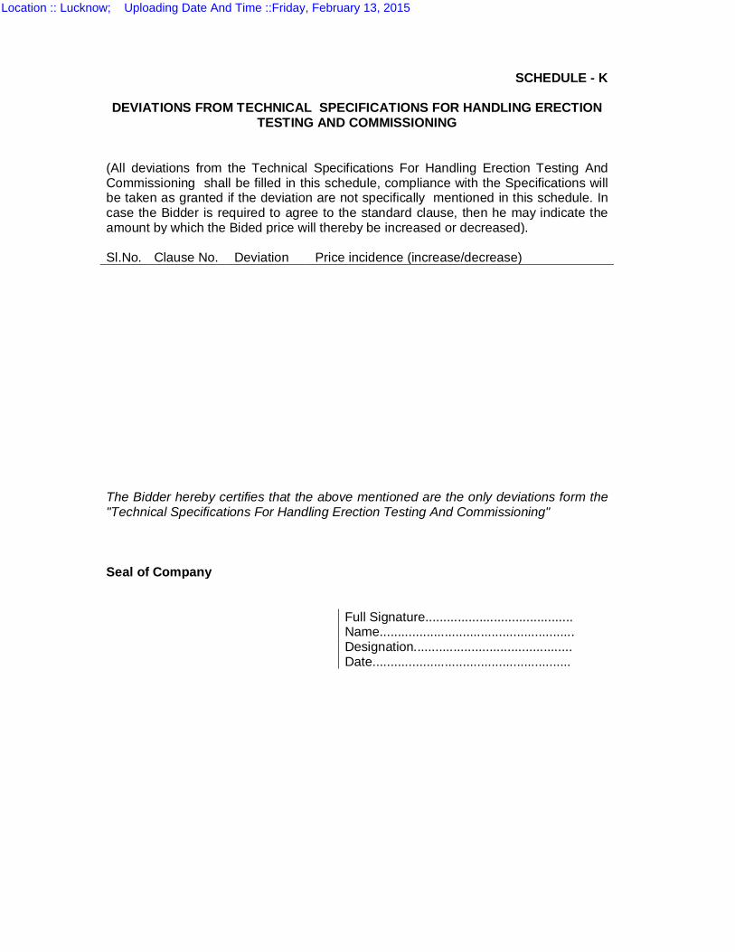
SCHEDULE - K
DEVIATIONS FROM TECHNICAL SPECIFICATIONS FOR HANDLING ERECTION
TESTING AND COMMISSIONING (All deviations from the Technical Specifications For Handling Erection Testing And Commissioning shall be filled in this schedule, compliance with the Specifications will be taken as granted if the deviation are not specifically mentioned in this schedule. In case the Bidder is required to agree to the standard clause, then he may indicate the amount by which the Bided price will thereby be increased or decreased). Sl.No. Clause No. Deviation Price incidence (increase/decrease) The Bidder hereby certifies that the above mentioned are the only deviations form the "Technical Specifications For Handling Erection Testing And Commissioning" Seal of Company Full Signature.........................................
Name...................................................... Designation............................................
Date.......................................................
Location :: Lucknow; Uploading Date And Time ::Friday, February 13, 2015
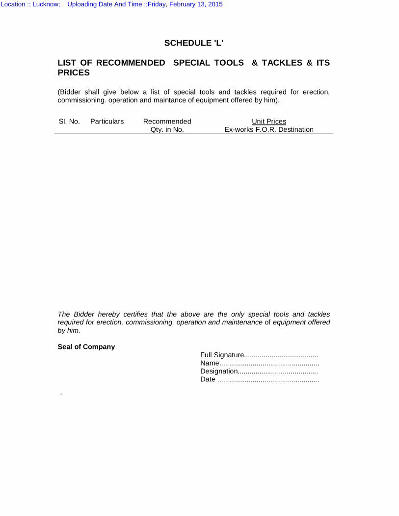
SCHEDULE 'L'
LIST OF RECOMMENDED SPECIAL TOOLS & TACKLES & ITS PRICES
(Bidder shall give below a list of special tools and tackles required for erection, commissioning. operation and maintance of equipment offered by him).
Sl. No. Particulars Recommended Qty. in No.
Unit Prices Ex-works F.O.R. Destination
The Bidder hereby certifies that the above are the only special tools and tackles required for erection, commissioning. operation and maintenance of equipment offered by him. Seal of Company Full Signature...................................... Name................................................... Designation......................................... Date ....................................................
.
Location :: Lucknow; Uploading Date And Time ::Friday, February 13, 2015
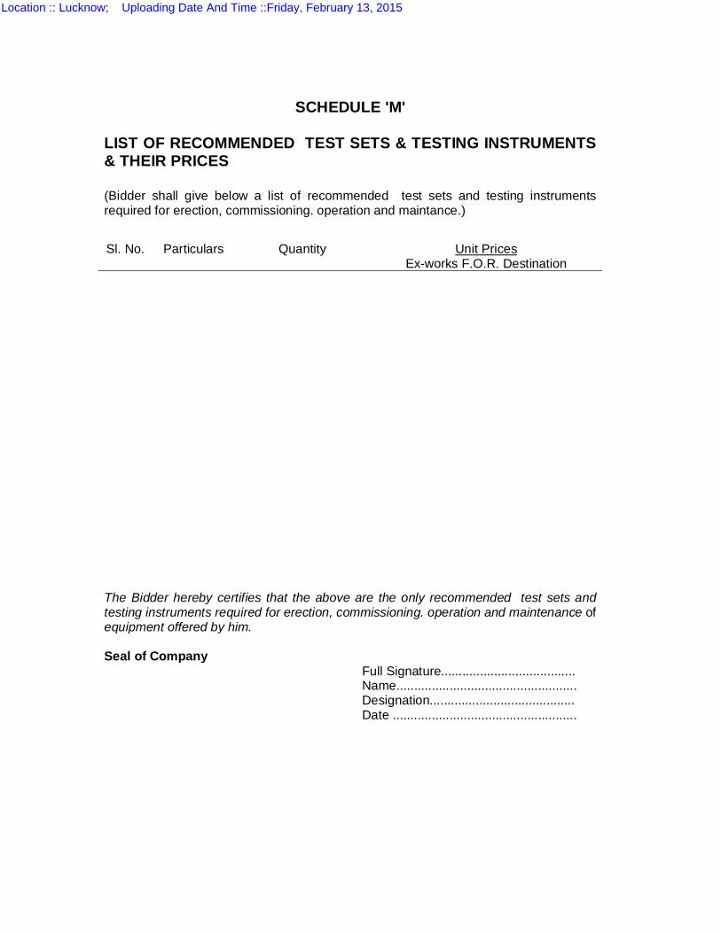
SCHEDULE 'M' LIST OF RECOMMENDED TEST SETS & TESTING INSTRUMENTS & THEIR PRICES
(Bidder shall give below a list of recommended test sets and testing instruments required for erection, commissioning. operation and maintance.)
Sl. No. Particulars Quantity Unit Prices Ex-works F.O.R. Destination
The Bidder hereby certifies that the above are the only recommended test sets and testing instruments required for erection, commissioning. operation and maintenance of equipment offered by him. Seal of Company Full Signature...................................... Name................................................... Designation......................................... Date ....................................................
Location :: Lucknow; Uploading Date And Time ::Friday, February 13, 2015
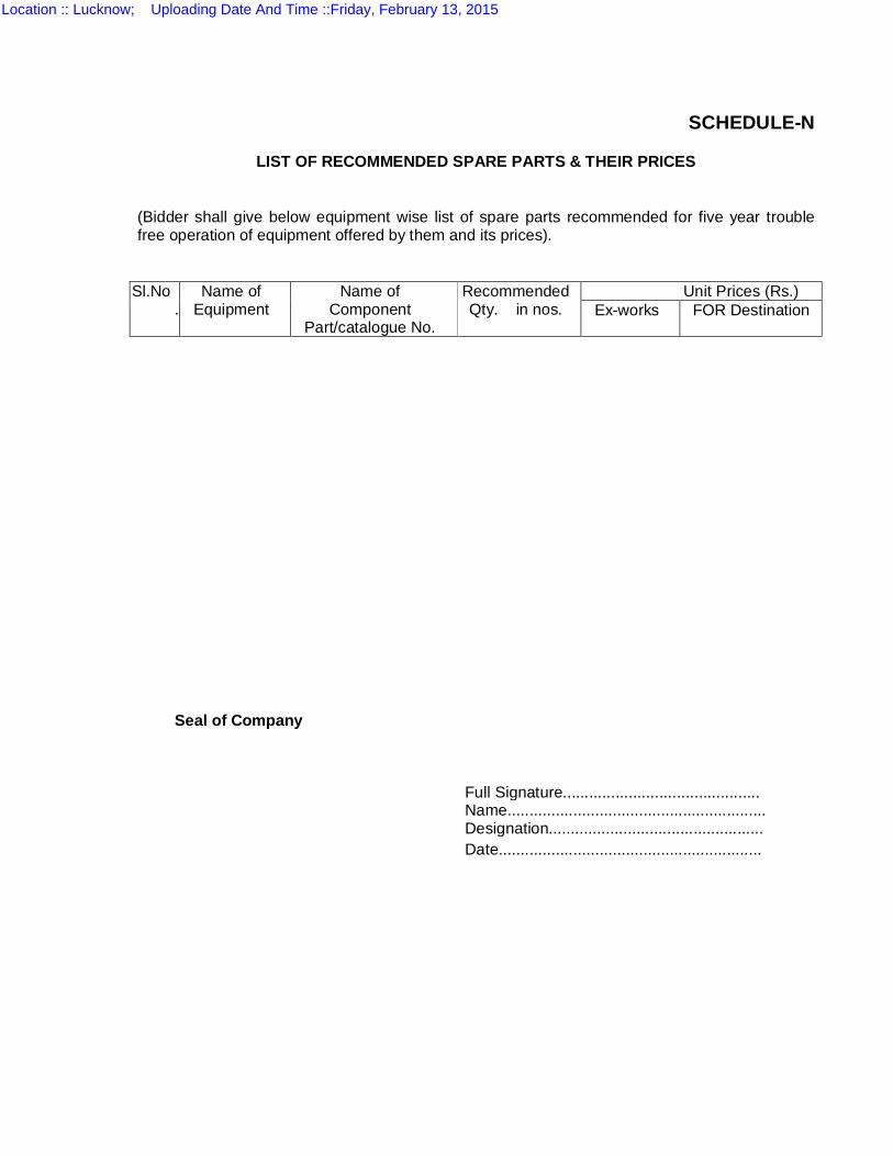
SCHEDULE-N
LIST OF RECOMMENDED SPARE PARTS & THEIR PRICES
(Bidder shall give below equipment wise list of spare parts recommended for five year trouble free operation of equipment offered by them and its prices).
Sl.No.
Name of Equipment
Name of Component
Part/catalogue No.
Recommended Qty. in nos.
Unit Prices (Rs.) Ex-works FOR Destination
Seal of Company
Full Signature............................................. Name...........................................................
Designation................................................. Date............................................................
Location :: Lucknow; Uploading Date And Time ::Friday, February 13, 2015
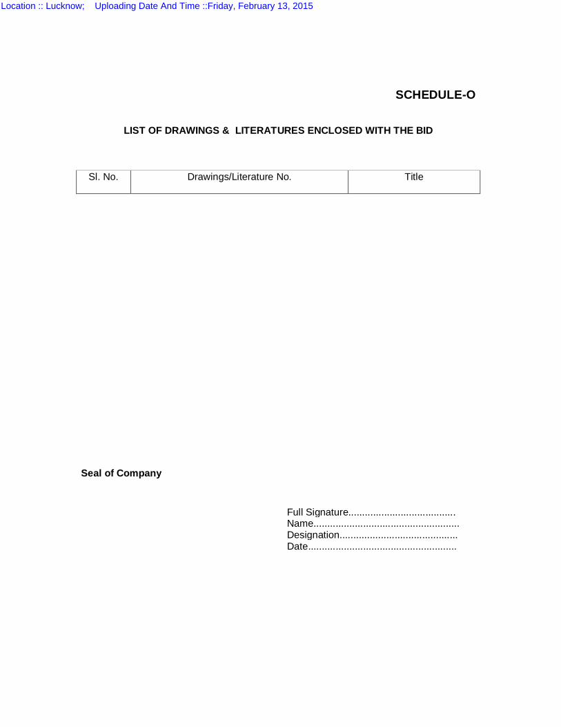
SCHEDULE-O
LIST OF DRAWINGS & LITERATURES ENCLOSED WITH THE BID
Sl. No.
Drawings/Literature No.
Title
Seal of Company Full Signature....................................... Name..................................................... Designation........................................... Date......................................................
Location :: Lucknow; Uploading Date And Time ::Friday, February 13, 2015

SCHEDULE P
SCHEDULE OF GUARANTEED COMPLETION / DELIVERY PERIOD
1.0 COMPLETION PERIOD The Substation shall be constructed, erected, tested, commissioned and completed in all respects within 12 months from the date of issue of letter of intent. The Bidder shall submit the Project Implementation Schedule and PERT with his Bid showing time taken for varioys deliveries/activities in weeks reckoned from the date of issue of letter of intent. 2.0 DELIVERY PERIOD The Civil works and deliveries of all equipments and materials shall match the above completion period. The delivery schedules of following major items may be specified in the table given below : S.N. Item Quantity Delivery Period in weeks
reckoned from date of issue of letter of intent.
Commencement Completion 1.0 Earthmat material 2.0 Anchor Bolts 3.0 Main Structures 4.0 Auxiliary Structures 5.0 Bus bar material for
main, transfer, jack buses & inter connections with equipments etc
6.0 250 KVA transformers
7.0 145 KV Circuit Breakers
8.0 33 KV Vaccum Circuit Breakers
9.0 10.0
145 KV C.T.s & C.V.T.s 33KV CT & PT
11.0 145 KV Isolators 36 KV Isolators
12.0 120 KV Surge Arrestors 30KV Surge Arrestor
13.0 All Contol & Relay Panels
14.0 All Batteries & Battery Chargers
Location :: Lucknow; Uploading Date And Time ::Friday, February 13, 2015
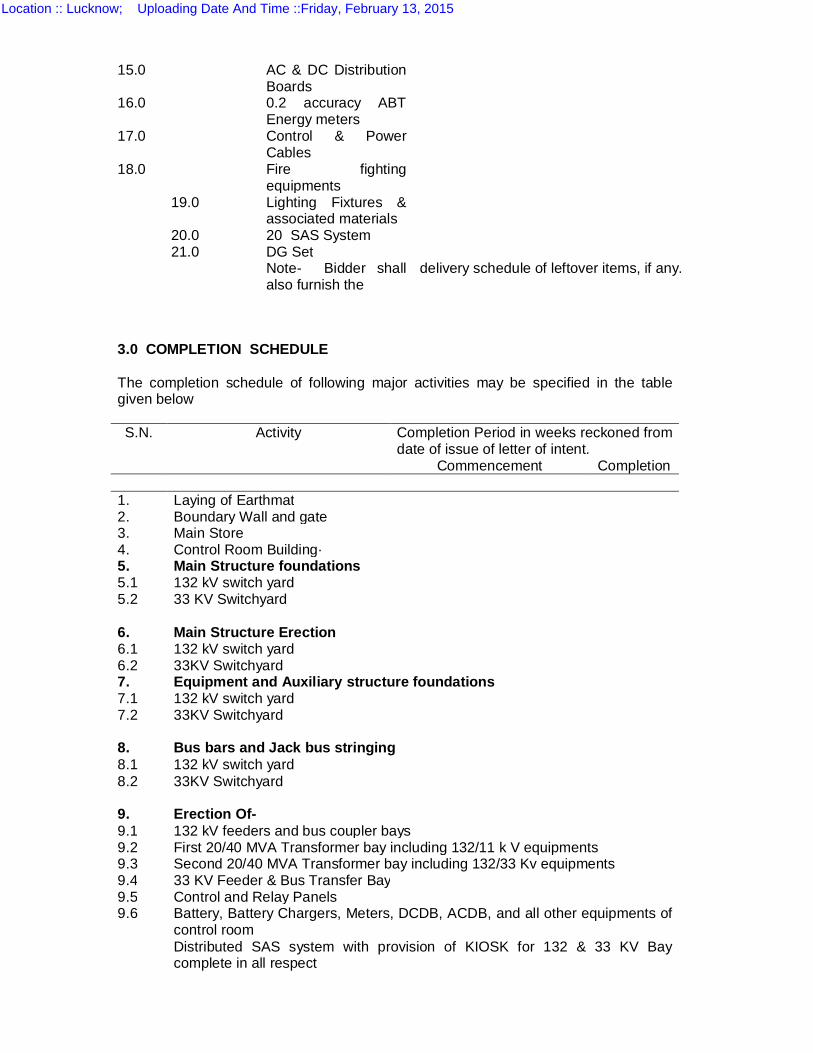
15.0 AC & DC Distribution Boards
16.0 0.2 accuracy ABT Energy meters
17.0 Control & Power Cables
18.0 Fire fighting equipments
19.0
20.0 21.0
Lighting Fixtures & associated materials 20 SAS System DG Set
Note- Bidder shall also furnish the
delivery schedule of leftover items, if any.
3.0 COMPLETION SCHEDULE The completion schedule of following major activities may be specified in the table given below S.N. Activity Completion Period in weeks reckoned from
date of issue of letter of intent. Commencement Completion
1. Laying of Earthmat 2. Boundary Wall and gate 3. Main Store 4. Control Room Building· 5. Main Structure foundations 5.1 5.2
132 kV switch yard 33 KV Switchyard
6. Main Structure Erection 6.1 6.2
132 kV switch yard 33KV Switchyard
7. Equipment and Auxiliary structure foundations 7.1 7.2
132 kV switch yard 33KV Switchyard
8. Bus bars and Jack bus stringing 8.1 8.2
132 kV switch yard 33KV Switchyard
9. Erection Of- 9.1 132 kV feeders and bus coupler bays 9.2 First 20/40 MVA Transformer bay including 132/11 k V equipments 9.3 9.4
Second 20/40 MVA Transformer bay including 132/33 Kv equipments 33 KV Feeder & Bus Transfer Bay
9.5 Control and Relay Panels 9.6 Battery, Battery Chargers, Meters, DCDB, ACDB, and all other equipments of
control room Distributed SAS system with provision of KIOSK for 132 & 33 KV Bay complete in all respect
Location :: Lucknow; Uploading Date And Time ::Friday, February 13, 2015
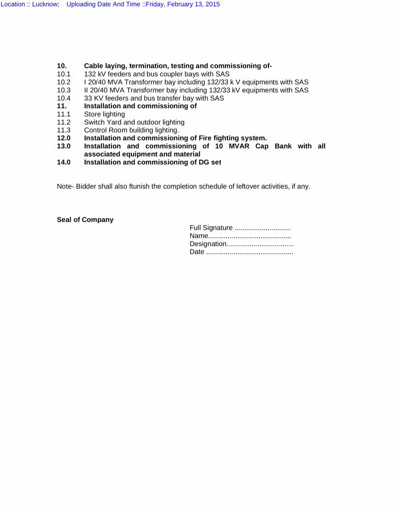
10. Cable laying, termination, testing and commissioning of- 10.1 132 kV feeders and bus coupler bays with SAS 10.2 I 20/40 MVA Transformer bay including 132/33 k V equipments with SAS 10.3 10.4
II 20/40 MVA Transformer bay including 132/33 kV equipments with SAS 33 KV feeders and bus transfer bay with SAS
11. Installation and commissioning of 11.1 Store lighting 11.2 Switch Yard and outdoor lighting 11.3 Control Room building lighting. 12.0 13.0 14.0
Installation and commissioning of Fire fighting system. Installation and commissioning of 10 MVAR Cap Bank with all associated equipment and material Installation and commissioning of DG set
Note- Bidder shall also ftunish the completion schedule of leftover activities, if any. Seal of Company Full Signature ............................. Name........................................... Designation................................... Date .............................................
Location :: Lucknow; Uploading Date And Time ::Friday, February 13, 2015

SCHEDULE - Q
SCHEDULE OF QUANTITIES & PRICES
Location :: Lucknow; Uploading Date And Time ::Friday, February 13, 2015
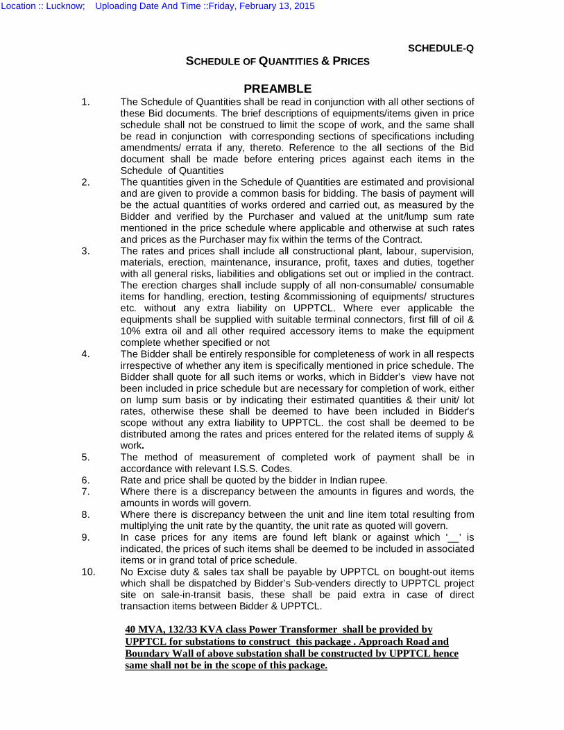
SCHEDULE-Q SCHEDULE OF QUANTITIES & PRICES
PREAMBLE
1. The Schedule of Quantities shall be read in conjunction with all other sections of these Bid documents. The brief descriptions of equipments/items given in price schedule shall not be construed to limit the scope of work, and the same shall be read in conjunction with corresponding sections of specifications including amendments/ errata if any, thereto. Reference to the all sections of the Bid document shall be made before entering prices against each items in the Schedule of Quantities
2. The quantities given in the Schedule of Quantities are estimated and provisional and are given to provide a common basis for bidding. The basis of payment will be the actual quantities of works ordered and carried out, as measured by the Bidder and verified by the Purchaser and valued at the unit/lump sum rate mentioned in the price schedule where applicable and otherwise at such rates and prices as the Purchaser may fix within the terms of the Contract.
3. The rates and prices shall include all constructional plant, labour, supervision, materials, erection, maintenance, insurance, profit, taxes and duties, together with all general risks, liabilities and obligations set out or implied in the contract. The erection charges shall include supply of all non-consumable/ consumable items for handling, erection, testing &commissioning of equipments/ structures etc. without any extra liability on UPPTCL. Where ever applicable the equipments shall be supplied with suitable terminal connectors, first fill of oil & 10% extra oil and all other required accessory items to make the equipment complete whether specified or not
4. The Bidder shall be entirely responsible for completeness of work in all respects irrespective of whether any item is specifically mentioned in price schedule. The Bidder shall quote for all such items or works, which in Bidder’s view have not been included in price schedule but are necessary for completion of work, either on lump sum basis or by indicating their estimated quantities & their unit/ lot rates, otherwise these shall be deemed to have been included in Bidder's scope without any extra liability to UPPTCL. the cost shall be deemed to be distributed among the rates and prices entered for the related items of supply & work.
5. The method of measurement of completed work of payment shall be in accordance with relevant I.S.S. Codes.
6. Rate and price shall be quoted by the bidder in Indian rupee. 7. Where there is a discrepancy between the amounts in figures and words, the
amounts in words will govern. 8. Where there is discrepancy between the unit and line item total resulting from
multiplying the unit rate by the quantity, the unit rate as quoted will govern. 9. In case prices for any items are found left blank or against which '__’ is
indicated, the prices of such items shall be deemed to be included in associated items or in grand total of price schedule.
10. No Excise duty & sales tax shall be payable by UPPTCL on bought-out items which shall be dispatched by Bidder’s Sub-venders directly to UPPTCL project site on sale-in-transit basis, these shall be paid extra in case of direct transaction items between Bidder & UPPTCL. 40 MVA, 132/33 KVA class Power Transformer shall be provided by UPPTCL for substations to construct this package . Approach Road and Boundary Wall of above substation shall be constructed by UPPTCL hence same shall not be in the scope of this package.
Location :: Lucknow; Uploading Date And Time ::Friday, February 13, 2015
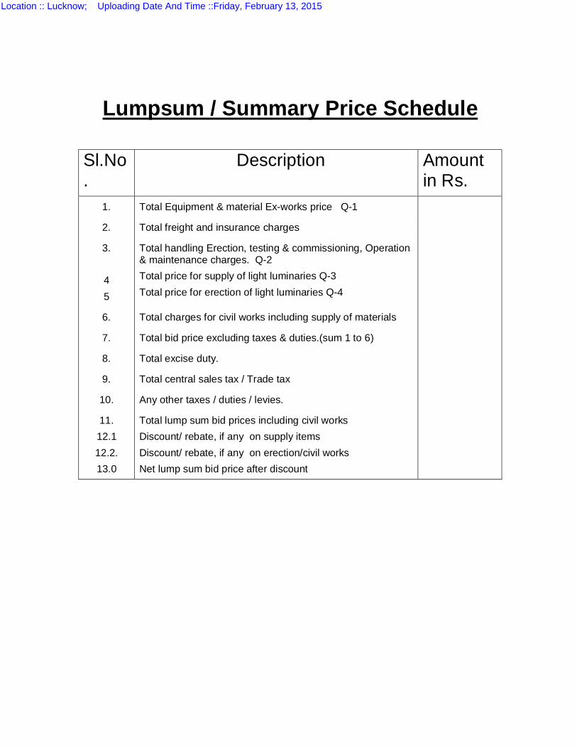
Lumpsum / Summary Price Schedule
Sl.No.
Description Amount in Rs.
1. Total Equipment & material Ex-works price Q-1
2. Total freight and insurance charges
3. 4 5
Total handling Erection, testing & commissioning, Operation & maintenance charges. Q-2 Total price for supply of light luminaries Q-3 Total price for erection of light luminaries Q-4
6. Total charges for civil works including supply of materials
7. Total bid price excluding taxes & duties.(sum 1 to 6)
8. Total excise duty.
9. Total central sales tax / Trade tax
10. Any other taxes / duties / levies.
11. 12.1 12.2. 13.0
Total lump sum bid prices including civil works Discount/ rebate, if any on supply items Discount/ rebate, if any on erection/civil works Net lump sum bid price after discount
Location :: Lucknow; Uploading Date And Time ::Friday, February 13, 2015
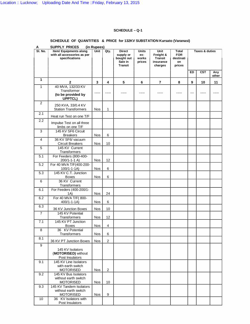
SCHEDULE – Q-1
SCHEDULE OF QUANTITIES & PRICE for 132KV SUBSTATION Kursato (Varanasi)
A SUPPLY PRICES (in Rupees) Sl. No. Item/ Equipments along
with all accessories as per specifications
Unit Qty. Direct supply or
bought out Sale in Transit
Units ex-
works prices
Unit Freight & Transit
insurance charges
Total FOR
destination
prices
Taxes & duties
ED CST Any other
1 2 3 4 5 6 7 8 9 10 11
1 40 MVA, 132/33 KV Transformer
(to be provided by UPPTCL)
----- ----- ----- ----- ----- ----- --- ----- -----
2 250 KVA, 33/0.4 KV Station Transformers Nos 1
2.1 Heat run Test on one T/F
2.2 Impulse Test on all three limbs on one T/F
3 145 KV SF6 Circuit Breakers Nos 6
4 36 KV SF6/ vacuum Circuit Breakers Nos 10
5 145 KV Current Transformers
5.1 For Feeders (800-400-200/1-1-1 A) Nos 12
5.2 For 40 MVA T/F(400-200-100/1-1-1A) Nos 6
5.3 145 KV C.T. Junction Boxes Nos 6
6 36 KV Current Transformers
6.1 For Feeders (400-200/1-1A) Nos 24
6.2 For 40 MVA T/F( 800-400/1-1-1A) Nos 6
6.3 36 KV Junction Boxes Nos 10
7 145 KV Potential Transformers Nos 12
7.1 145 KV PT Junction Boxes Nos 4
8 36 KV Potential Transformers Nos 6
8.1 36 KV PT Junction Boxes Nos 2
9 145 KV Isolators
(MOTORISED) without Post Insulators
9.1 145 KV Line Isolators with earth switch
MOTORISED Nos 2 9.2 145 KV Bus Isolators
without earth switch MOTORISED Nos 10
9.3 145 KV Tandem Isolators without earth switch
MOTORISED Nos 9 10 36 KV Isolators with
Post Insulators
Location :: Lucknow; Uploading Date And Time ::Friday, February 13, 2015
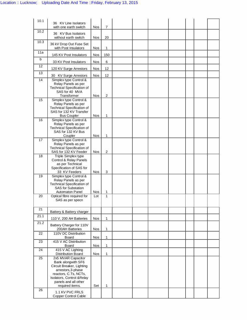
10.1 36 KV Line Isolators with one earth switch Nos 7
10.2 36 KV Bus Isolators without earth switch Nos 20
10.3 36 kV Drop Out Fuse Set with Post Insulators Nos 1
11a 145 KV Post Insulators Nos 150
b 33 KV Post Insulators Nos 6
12 120 KV Surge Arrestors Nos 12
13 30 KV Surge Arrestors Nos 12
14 Simplex type Control & Relay Panels as per
Technical Specification of SAS for 40 MVA
Transformer Nos 2 15 Simplex type Control &
Relay Panels as per Technical Specification of SAS for 132 KV Transfer
Bus Coupler Nos 1 16 Simplex type Control &
Relay Panels as per Technical Specification of
SAS for 132 KV Bus Coupler Nos 1
17 Simplex type Control & Relay Panels as per
Technical Specification of SAS for 132 KV Feeder Nos 2
18 Triple Simplex type Control & Relay Panels
as per Technical Specification of SAS for
33 KV Feeders Nos 3 19 Simplex type Control &
Relay Panels as per Technical Specification of
SAS for Substation Automaton Panel Nos 1
20 Optical fibre required for SAS as per specn
Lot 1
21
Battery & Battery charger 21.1
110 V, 200 AH Batteries Nos 1 21.2 Battery Charger for 110V
200AH Batteries Nos 1 22 110V DC Distribution
Board Nos 1 23 415 V AC Distribution
Board Nos 1 24 415 V AC Lighting
Distribution Board Nos 1 25 2x5 MVAR Capacitor
Bank alongwith SF6 Circuit Breaker, Lighting
arrestors,3-phase reactors, C.Ts, NCTs,
Isolators, Control &Relay panels and all other
required items. Set 1 26 1.1 KV PVC FRLS
Copper Control Cable
Location :: Lucknow; Uploading Date And Time ::Friday, February 13, 2015
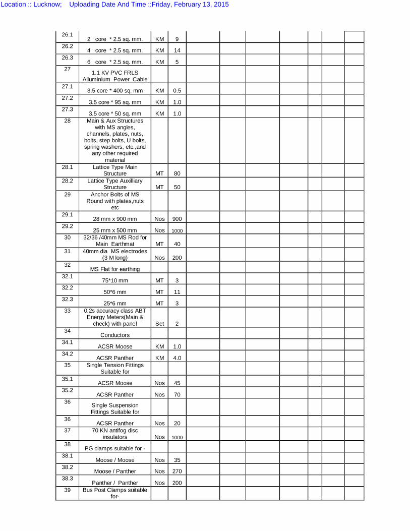
26.1 2 core * 2.5 sq. mm. KM 9
26.2 4 core * 2.5 sq. mm. KM 14
26.3 6 core * 2.5 sq. mm. KM 5
27 1.1 KV PVC FRLS Alluminium Power Cable
27.1 3.5 core * 400 sq. mm KM 0.5
27.2 3.5 core * 95 sq. mm KM 1.0
27.3 3.5 core * 50 sq. mm KM 1.0
28 Main & Aux Structures with MS angles,
channels, plates, nuts, bolts, step bolts, U bolts, spring washers, etc.,and
any other required material
28.1 Lattice Type Main Structure MT 80
28.2 Lattice Type Auxilliary Structure MT 50
29 Anchor Bolts of MS Round with plates,nuts
etc 29.1
28 mm x 900 mm Nos 900 29.2
25 mm x 500 mm Nos 1000 30 32/36 /40mm MS Rod for
Main Earthmat MT 40 31 40mm dia MS electrodes
(3 M long) Nos 200 32
MS Flat for earthing 32.1
75*10 mm MT 3 32.2
50*6 mm MT 11 32.3
25*6 mm MT 3 33 0.2s accuracy class ABT
Energy Meters(Main & check) with panel Set 2
34 Conductors
34.1 ACSR Moose KM 1.0
34.2 ACSR Panther KM 4.0
35 Single Tension Fittings Suitable for
35.1 ACSR Moose Nos 45
35.2 ACSR Panther Nos 70
36 Single Suspension Fittings Suitable for
36 ACSR Panther Nos 20
37 70 KN antifog disc insulators Nos 1000
38 PG clamps suitable for -
38.1 Moose / Moose Nos 35
38.2 Moose / Panther Nos 270
38.3 Panther / Panther Nos 200
39 Bus Post Clamps suitable for-
Location :: Lucknow; Uploading Date And Time ::Friday, February 13, 2015
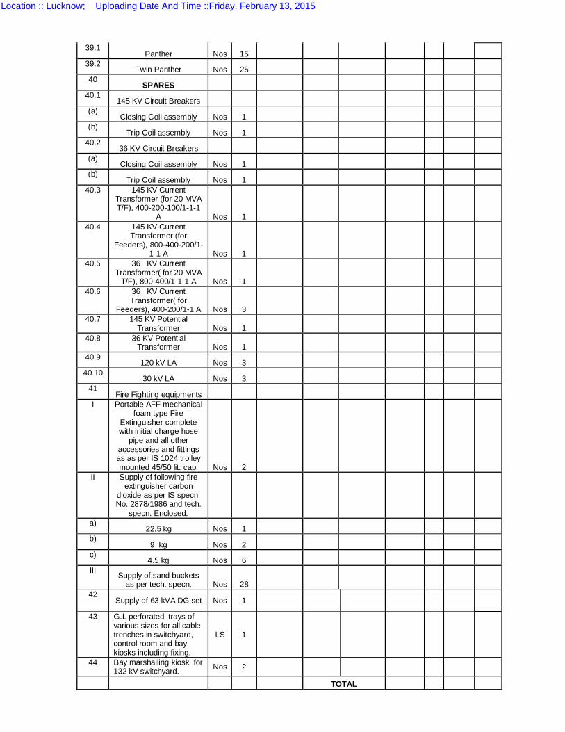
39.1 Panther Nos 15
39.2 Twin Panther Nos 25
40 SPARES
40.1 145 KV Circuit Breakers
(a) Closing Coil assembly Nos 1
(b) Trip Coil assembly Nos 1
40.2 36 KV Circuit Breakers
(a) Closing Coil assembly Nos 1
(b) Trip Coil assembly Nos 1
40.3 145 KV Current Transformer (for 20 MVA T/F), 400-200-100/1-1-1
A Nos 1 40.4 145 KV Current
Transformer (for Feeders), 800-400-200/1-
1-1 A Nos 1 40.5 36 KV Current
Transformer( for 20 MVA T/F), 800-400/1-1-1 A Nos 1
40.6 36 KV Current Transformer( for
Feeders), 400-200/1-1 A Nos 3 40.7 145 KV Potential
Transformer Nos 1 40.8 36 KV Potential
Transformer Nos 1 40.9
120 kV LA Nos 3 40.10
30 kV LA Nos 3 41
Fire Fighting equipments I Portable AFF mechanical
foam type Fire Extinguisher complete with initial charge hose
pipe and all other accessories and fittings as as per IS 1024 trolley mounted 45/50 lit. cap. Nos 2
II Supply of following fire extinguisher carbon
dioxide as per IS specn. No. 2878/1986 and tech.
specn. Enclosed. a)
22.5 kg Nos 1 b)
9 kg Nos 2 c)
4.5 kg Nos 6 III Supply of sand buckets
as per tech. specn. Nos 28 42
Supply of 63 kVA DG set Nos 1
43 G.I. perforated trays of various sizes for all cable trenches in switchyard, control room and bay kiosks including fixing.
LS 1
44 Bay marshalling kiosk for
132 kV switchyard. Nos 2 TOTAL
Location :: Lucknow; Uploading Date And Time ::Friday, February 13, 2015
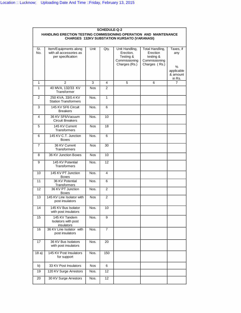
SCHEDULE-Q-2 HANDLING ERECTION TESTING COMMISSIONING OPERATION AND MAINTENANCE
CHARGES 132KV SUBSTATION KURSATO (VARANASI)
SI. No.
Item/Equipments along with all accessories as
per specification
Unit Qty. Unit Handling, Erection, Testing &
Commissioning Charges (Rs.)
Total Handling, Erection testing &
Commissioning Charges ( Rs.)
Taxes, if any
% applicable & amount
in Rs. 1 2 3 4 5 6 7 1 40 MVA, 132/33 KV
Transformer Nos 2
2 250 KVA, 33/0.4 KV Station Transformers
Nos. 1
3 145 KV SF6 Circuit Breakers
Nos. 6
4 36 KV SF6/Vacuum Circuit Breakers
Nos. 10
5 145 KV Current Transformers
Nos 18
6 145 KV C.T. Junction Boxes
Nos. 6
7 36 KV Current Transformers
Nos 30
8 36 KV Junction Boxes Nos 10
9 145 KV Potential Transformers
Nos. 12
10 145 KV PT Junction Boxes
Nos. 4
11 36 KV Potential Transformers
Nos. 6
12 36 KV PT Junction Boxes
Nos. 2
13 145 KV Line Isolator with post insulators
Nos 2
14 145 KV Bus Isolator with post insulators
Nos. 10
15 145 KV Tandem Isolators with post
insulators
Nos. 9
16 36 KV Line Isolator with post insulators
Nos. 7
17 36 KV Bus Isolators with post insulators
Nos. 20
18 a) 145 KV Post Insulators for support
Nos. 150
b) 33 KV Post Insulators Nos 6
19 120 KV Surge Arrestors Nos. 12
20 30 KV Surge Arrestors Nos. 12
Location :: Lucknow; Uploading Date And Time ::Friday, February 13, 2015
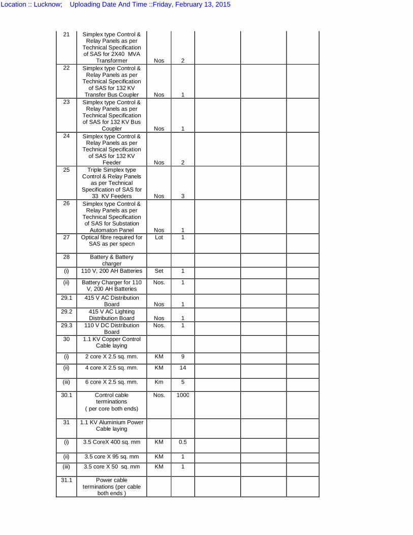
21 Simplex type Control & Relay Panels as per
Technical Specification of SAS for 2X40 MVA
Transformer Nos 2
22 Simplex type Control & Relay Panels as per
Technical Specification of SAS for 132 KV
Transfer Bus Coupler Nos 1
23 Simplex type Control & Relay Panels as per
Technical Specification of SAS for 132 KV Bus
Coupler Nos 1
24 Simplex type Control & Relay Panels as per
Technical Specification of SAS for 132 KV
Feeder Nos 2
25 Triple Simplex type Control & Relay Panels
as per Technical Specification of SAS for
33 KV Feeders Nos 3
26 Simplex type Control & Relay Panels as per
Technical Specification of SAS for Substation
Automaton Panel Nos 1
27 Optical fibre required for SAS as per specn
Lot 1
28 Battery & Battery charger
(i) 110 V, 200 AH Batteries Set 1
(ii) Battery Charger for 110 V, 200 AH Batteries
Nos. 1
29.1 415 V AC Distribution Board Nos 1
29.2 415 V AC Lighting Distribution Board Nos 1
29.3 110 V DC Distribution Board
Nos. 1
30 1.1 KV Copper Control Cable laying
(i) 2 core X 2.5 sq. mm. KM 9
(ii) 4 core X 2.5 sq. mm. KM 14
(iii) 6 core X 2.5 sq. mm. Km 5
30.1 Control cable terminations
Nos. 1000
( per core both ends)
31 1.1 KV Aluminium Power Cable laying
(i) 3.5 CoreX 400 sq. mm KM 0.5
(ii) 3.5 core X 95 sq. mm KM 1
(iii) 3.5 core X 50 sq. mm KM 1
31.1 Power cable terminations (per cable
both ends )
Location :: Lucknow; Uploading Date And Time ::Friday, February 13, 2015
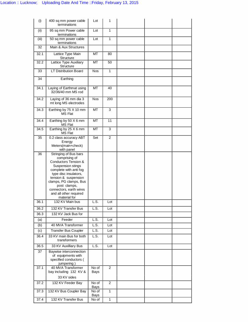
(i) 400 sq mm power cable terminations
Lot 1
(ii) 95 sq mm Power cable terminations
Lot 1
(iii) 50 sq mm power cable terminations
Lot 1
32 Main & Aux Structures
32.1 Lattice Type Main Structure
MT 80
32.2 Lattice Type Auxiliary Structure
MT 50
33 LT Distribution Board Nos 1
34 Earthing
34.1 Laying of Earthmat using 32/36/40 mm MS rod
MT 40
34.2 Laying of 36 mm dia 3 mt long MS electrodes
Nos 200
34.3 Earthing by 75 X 10 mm MS Flat
MT 3
34.4 Earthing by 50 X 6 mm MS Flat
MT 11
34.5 Earthing by 25 X 6 mm MS Flat
MT 3
35 0.2 class accuracy ABT Energy
Meters(main+check) with panel
Set 2
36 Stringing of Bus bars comprising of
Conductors Tension & Suspension stings
complete with anti fog type disc insulators,
tension & suspension clamps, PG clamps, Bus
post clamps, connectors, earth wires and all other required
material for
36.1 132 KV Main bus L.S. Lot
36.2 132 KV Transfer Bus L.S. Lot 36.3 132 KV Jack Bus for (a) Feeder L.S. Lot (b) 40 MVA Transformer L.S. Lot (c) Transfer Bus Coupler L.S. Lot
36.4 33 KV main Bus for both transformers
L.S. Lot
36.5 33 KV Auxilliary Bus L.S. Lot 37 Baywise interconnection
of equipments with specified conductors (
jumpering )
37.1 40 MVA Transformer bay including 132 KV &
No of Bays
2
33 KV sides 37.2 132 KV Feeder Bay No of
Bays 2
37.3 132 KV Bus Coupler Bay No of Bays
1
37.4 132 KV Transfer Bus No of 1
Location :: Lucknow; Uploading Date And Time ::Friday, February 13, 2015
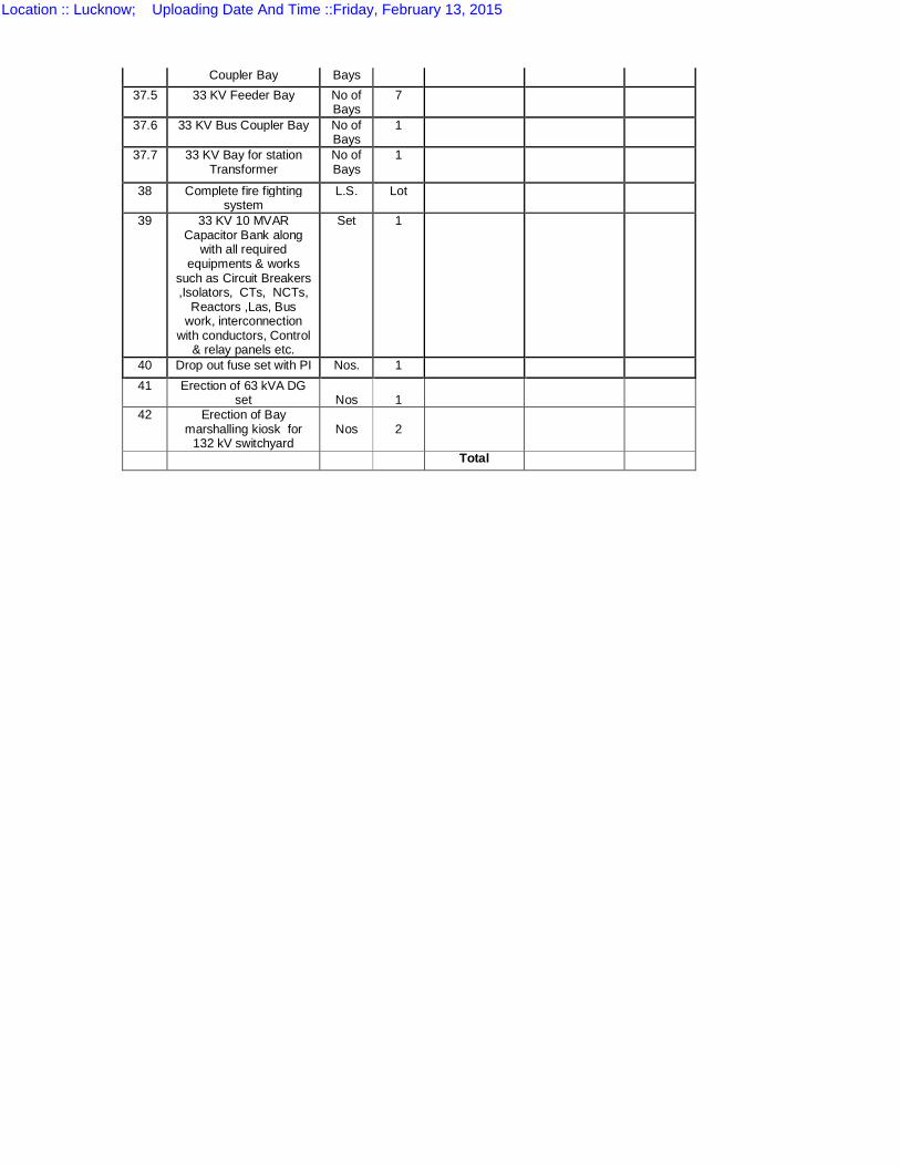
Coupler Bay Bays 37.5 33 KV Feeder Bay No of
Bays 7
37.6 33 KV Bus Coupler Bay No of Bays
1
37.7 33 KV Bay for station Transformer
No of Bays
1
38 Complete fire fighting system
L.S. Lot
39 33 KV 10 MVAR Capacitor Bank along
with all required equipments & works
such as Circuit Breakers ,Isolators, CTs, NCTs,
Reactors ,Las, Bus work, interconnection
with conductors, Control & relay panels etc.
Set 1
40 Drop out fuse set with PI Nos. 1 41 Erection of 63 kVA DG
set Nos 1
42 Erection of Bay marshalling kiosk for
132 kV switchyard Nos 2
Total
Location :: Lucknow; Uploading Date And Time ::Friday, February 13, 2015
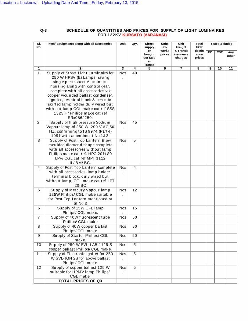
Q-3 SCHEDULE OF QUANTITIES AND PRICES FOR SUPPLY OF LIGHT LUMINAIRES FOR 132KV KURSATO (VARANASI)
Sl. No.
Item/ Equipments along with all accessories Unit Qty. Direct supply
or bought out Sale
in Transit
Units ex-
works prices
Unit Freight
& Transit insurance charges
Total FOR
destin ation
prices
Taxes & duties
ED CST Any other
1 2 3 4 5 6 7 8 9 10 11 1. Supply of Street Light Luminairs for
250 W HPSV (E) Lamps having single piece sheet Aluminium
housing along with control gear, complete with all accessories viz
copper wounded ballast condenser, ignitor, terminal block & ceremic
skirted lamp holder duly wired but with out lamp CGL make cat ref SSS
1325 H/Philips make cat ref SRx086/250.
Nos.
40
2. Supply of high pressure Sodium Vapour lamp of 250 W, 200 V AC 50
HZ, confirming to IS 9974 (Part-I) 1981 with amendment No.1&2.
Nos.
45
3 Supply of Post Top Lantern Blow moulded diamond shape complete with all accessories without lamp Philips make cat ref. HPC 201/80
LPF/CGL cat.ref.MPT 1112 IL/BM/BC.
Nos.
5
4 Supply of Post Top Lantern complete with all accessories, lamp holder,
terminal block, duly wired but without lamp, CGL make cat.ref. IPT
20 BC
Nos.
4
5 Supply of Mercury Vapour lamp 125W Philips/CGL make suitable for Post Top Lantern mentioned at
Sl.No.3
Nos.
12
6 Supply of 15W CFL lamp Philips/CGL make.
Nos.
15
7 Supply of 40W fluorescent tube Philips/CGL make
Nos.
50
8 Supply of 40W copper ballast Philips/CGL make.
Nos.
50
9 Supply of Starter Philips/CGL make.
Nos.
50
10 Supply of 250 W SVL-LAB 1125 S copper ballast Philips/CGL make.
Nos.
5
11 Supply of Electronic igniter for 250 W SVL-IGN 2S for above ballast
Philips/CGL make.
Nos.
5
12 Supply of copper ballast 125 W suitable for HPMV lamp Philips/
CGL make.
Nos.
5
TOTAL PRICES OF Q3
Location :: Lucknow; Uploading Date And Time ::Friday, February 13, 2015
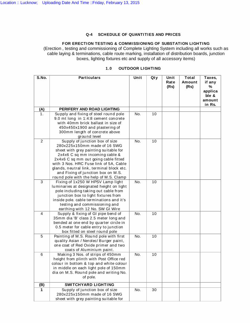
Q-4 SCHEDULE OF QUANTITIES AND PRICES
FOR ERECTION TESTING & COMMISSIONING OF SUBSTATION LIGHTING (Erection , testing and commissioning of Complete Lighting System including all works such as
cable laying & terminations, cable route marking, installation of distribution boards, junction boxes, lighting fixtures etc and supply of all accessory items)
1.0 OUTDOOR LIGHTING
S.No. Particulars Unit Qty Unit
Rate (Rs)
Total Amount
(Rs)
Taxes, if any
% applicable &
amount in Rs.
(A) PERIFERY AND ROAD LIGHTING 1. Supply and fixing of steel round pole
9.0 mt long in 1:4:8 cement concrete with 40mm brick ballast in size of 450x450x1900 and plastering of 300mm length of concrete above
ground level
No. 10
2 Supply of junction box of size 280x225x150mm made of 16 SWG sheet with grey painting suitable for 2x4x6 C sq mm incoming cable &
2x4x6 C sq mm out going cable fitted with 3 Nos. HRC Fuse link of 5A, Cable glands, neutral link, terminal block etc.
and Fixing of junction box on M.S. round pole with the help of M.S. Clamp
No. 10
3 Fixing of 1x250 W HPSV Lamp light luminaries at designated height on light
pole including taking out cable from junction box to light fixtures from
inside pole. cable terminations and it’s testing and commissioning and earthing with 12 No. SW GI Wire
No. 10
4 Supply & fixing of GI pipe bend of 35mm dia 'B' class 2.5 meter long and bended at one end by quarter circle in 0.5 meter for cable entry to junction
box fitted on steel round pole
No. 10
5 Painting of M.S. Round pole with first quality Asian /Nerolec/Burger paint, one coat of Red Oxide primer and two
coats of Aluminium paint.
No. 10
6 Making 3 Nos. of strips of 450mm height from plinth with Post Office red
colour in bottom & top and white colour in middle on each light pole of 150mm dia on M.S. Round pole and writing No.
of pole.
No. 10
(B) SWITCHYARD LIGHTING 1 Supply of junction box of size
280x225x150mm made of 16 SWG sheet with grey painting suitable for
No. 30
Location :: Lucknow; Uploading Date And Time ::Friday, February 13, 2015
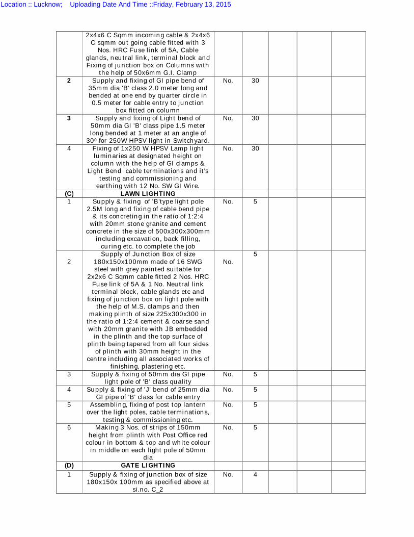
2x4x6 C Sqmm incoming cable & 2x4x6 C sqmm out going cable fitted with 3
Nos. HRC Fuse link of 5A, Cable glands, neutral link, terminal block and Fixing of junction box on Columns with
the help of 50x6mm G.I. Clamp 2 Supply and fixing of GI pipe bend of
35mm dia 'B' class 2.0 meter long and bended at one end by quarter circle in 0.5 meter for cable entry to junction
box fitted on column
No. 30
3 Supply and fixing of Light bend of 50mm dia GI 'B' class pipe 1.5 meter long bended at 1 meter at an angle of
300 for 250W HPSV light in Switchyard.
No. 30
4 Fixing of 1x250 W HPSV Lamp light luminaries at designated height on
column with the help of GI clamps & Light Bend cable terminations and it’s
testing and commissioning and earthing with 12 No. SW GI Wire.
No. 30
(C) LAWN LIGHTING 1 Supply & fixing of 'B'type light pole
2.5M long and fixing of cable bend pipe & its concreting in the ratio of 1:2:4
with 20mm stone granite and cement concrete in the size of 500x300x300mm
including excavation, back filling, curing etc. to complete the job
No. 5
2
Supply of Junction Box of size 180x150x100mm made of 16 SWG steel with grey painted suitable for
2x2x6 C Sqmm cable fitted 2 Nos. HRC Fuse link of 5A & 1 No. Neutral link terminal block, cable glands etc and
fixing of junction box on light pole with the help of M.S. clamps and then
making plinth of size 225x300x300 in the ratio of 1:2:4 cement & coarse sand with 20mm granite with JB embedded
in the plinth and the top surface of plinth being tapered from all four sides
of plinth with 30mm height in the centre including all associated works of
finishing, plastering etc.
No.
5
3 Supply & fixing of 50mm dia GI pipe light pole of 'B' class quality
No. 5
4 Supply & fixing of 'J' bend of 25mm dia GI pipe of 'B' class for cable entry
No. 5
5 Assembling, fixing of post top lantern over the light poles, cable terminations,
testing & commissioning etc.
No. 5
6 Making 3 Nos. of strips of 150mm height from plinth with Post Office red
colour in bottom & top and white colour in middle on each light pole of 50mm
dia
No. 5
(D) GATE LIGHTING 1 Supply & fixing of junction box of size
180x150x 100mm as specified above at si.no. C_2
No. 4
Location :: Lucknow; Uploading Date And Time ::Friday, February 13, 2015

2 Assembling, fixing of post top lantern type PT 20B for 100/200 W GLS lamp
cable terminations, testing and ,commissioning
No. 4
(E) CABLE LAYING AND TERMINATIONS 1 Laying of 4cx2.5 sq mm copper control
cable from control room to various point and for lawn lighting in excavated
trench
M 100
2 Laying of 2cx2.5 sq mm Copper control cable for lighting in switchyard
periphery, road etc. in excavated trench
M 500
3. Taking out above cable from junction box to light fittings fixed over the
column by fixing GI clamps of 40x5mm flat with each crossed bracing on
structures proper dressing etc
M 500
4. Excavation of trench of size 300 x 600 mm for laying of cable, putting ganga sand & Ist class bricks over the cable
and then earth filling etc.
500
5 Supply & fixing of Cable marker made of cast iron
No. 60
2.0 INDOOR LIGHTING FOR CONTROL ROOM AND STORE
S.No PARTICULARS Unit Qty. Rate Amount
1 Wiring for light point/fan point/ Exhaust Fan point/Call bell point with 3/22, 1.5mm2 PVC insulated copper
conductor in PVC conduit concealed in wall with 2.24mm dia bare copper earth continuity wire & piano type switches
etc. complete in all respect.
Nos. 70
2 Wiring for 3 Pin 5A light plug point socked outlet on existing switch board
with 3/22, 1.5mm2 PVC insulated copper conductor in PVC conduit
concealed in wall with 2.24mm dia bare copper earth wire continuity along with
piano type switch complete in all respect.
Nos. 12
3 Supply and fixing of metal box of size 180x100x80mm deep in recess with
suitable size of white laminated sheet cover in front including providing &
fixing 3 pin 15 A socket & switch connection piano type with 7/22,
4.0mm2 PVC insulated copper conductor concealed in wall with
2.24mm dia bare copper earth wire continuity complete in all respect.
Nos. 8
4 Supply & wiring of sub main with PVC insulated copper wire of size & no. as detailed below along with 2.24mm dia bare copper earth wire continuity in
PVC conduit concealed in wall complete in all respect.
4.1 2x4mm2 with 1 No. earth wire M 40
Location :: Lucknow; Uploading Date And Time ::Friday, February 13, 2015
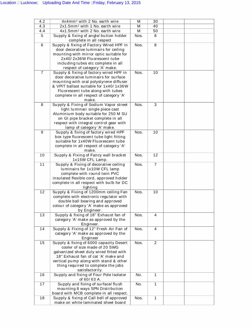
4.2 4x4mm2 with 2 No. earth wire M 30 4.3 2x1.5mm2 with 1 No. earth wire M 40 4.4 4x1.5mm2 with 2 No. earth wire M 50 5 Supply & fixing of angle/button holder
complete in all respect Nos. 8
6 Supply & fixing of Factory Wired HPF in door decorative luminairs for ceiling
mounting with mirror optic suitable for 2x40/2x36W Fluorescent tube
including tubes etc complete in all respect of category 'A' make.
Nos. 8
7 Supply & fixing of factory wired HPF in door decorative luminairs for surface
mounting with oral polystyrene diffuser & VPIT ballast suitable for 1x40/1x36W
Fluorescent tube along with tubes complete in all respect of category 'A'
make.
Nos. 10
8 Supply & Fixing of Sodium Vapor street light luminair single piece cast
Aluminium body suitable for 250 M SU on GI pipe bracket complete in all
respect with integral control gear with lamp of category 'A' make.
Nos. 3
9 Supply & fixing of factory wired HPF box type fluorescent tube light fitting suitable for 1x40W Fluorescent tube complete in all respect of category 'A'
make.
Nos. 10
10 Supply & Fixing of Fancy wall bracket 1x15W CFL Lamp.
Nos. 12
11 Supply & Fixing of decorative ceiling luminairs for 1x10W CFL lamp complete with round twin PVC
insulated flexible cord, approved holder complete in all respect with bulb for DC
lighting
Nos. 7
12 Supply & Fixing of 1200mm ceiling Fan complete with electronic regulator with
double ball bearing and approved colour of category 'A' make as approved
by Engineer.
Nos. 10
13 Supply & fixing of 18" Exhaust fan of category 'A' make as approved by the
Engineer.
Nos. 4
14 Supply & Fixing of 12" Fresh Air Fan of category 'A' make as approved by the
Engineer
Nos. 4
15 Supply & fixing of 6000 capacity Desert cooler of size made of 20 SWG
galvanized sheet duly wired fitted with 18" Exhaust fan of cat 'A' make and
vertical pump along with stand & other thing required to complete the jobs
satisfactorily.
Nos. 2
16 Supply and fixing of Four Pole Isolator of 60/63 A.
No. 1
17 Supply and fixing of surface/flush mounting 8 ways SPN Distribution
board with MCB complete in all respect.
No. 1
18 Supply & fixing of Call bell of approved make on white laminated sheet board
Nos. 1
Location :: Lucknow; Uploading Date And Time ::Friday, February 13, 2015
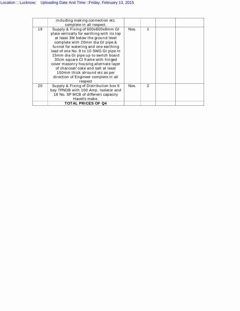
including making connection etc. complete in all respect.
19 Supply & Fixing of 600x800x8mm GI plate vertically for earthing with its top
at least 3M below the ground level complete with 20mm dia GI pipe &
funnel for watering and one earthing lead of one No. 8 to 10 SWG GI pipe in 15mm dia GI pipe up to switch board 30cm square CI frame with hinged
cover masonry housing alternate layer of charcoal/coke and salt at least 150mm thick alround etc as per
direction of Engineer complete in all respect
Nos. 1
20 Supply & Fixing of Distribution box 6 bay TPNDB with 100 Amp. Isolator and
18 No. SP MCB of different capacity Havells make.
Nos. 2
TOTAL PRICES OF Q4
Location :: Lucknow; Uploading Date And Time ::Friday, February 13, 2015
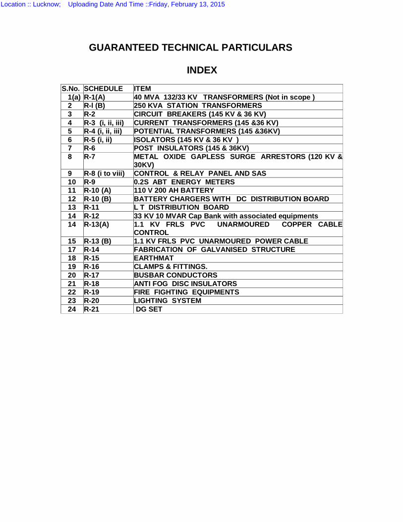
GUARANTEED TECHNICAL PARTICULARS
INDEX
S.No. SCHEDULE ITEM
1(a) R-1(A) 40 MVA 132/33 KV TRANSFORMERS (Not in scope ) 2 R-l (B) 250 KVA STATION TRANSFORMERS 3 R-2 CIRCUIT BREAKERS (145 KV & 36 KV) 4 R-3 (i, ii, iii) CURRENT TRANSFORMERS (145 &36 KV) 5 R-4 (i, ii, iii) POTENTIAL TRANSFORMERS (145 &36KV) 6 R-5 (i, ii) ISOLATORS (145 KV & 36 KV ) 7 R-6 POST INSULATORS (145 & 36KV) 8 R-7 METAL OXIDE GAPLESS SURGE ARRESTORS (120 KV &
30KV) 9 R-8 (i to viii) CONTROL & RELAY PANEL AND SAS 10 R-9 0.2S ABT ENERGY METERS 11 R-10 (A) 110 V 200 AH BATTERY 12 R-10 (B) BATTERY CHARGERS WITH DC DISTRIBUTION BOARD 13 R-11 L T DISTRIBUTION BOARD 14 R-12 33 KV 10 MVAR Cap Bank with associated equipments 14 R-13(A) 1.1 KV FRLS PVC UNARMOURED COPPER CABLE
CONTROL 15 R-13 (B) 1.1 KV FRLS PVC UNARMOURED POWER CABLE 17 R-14 FABRICATION OF GALVANISED STRUCTURE 18 R-15 EARTHMAT 19 R-16 CLAMPS & FITTINGS. 20 R-17 BUSBAR CONDUCTORS 21 R-18 ANTI FOG DISC INSULATORS 22 R-19 FIRE FIGHTING EQUIPMENTS 23 R-20 LIGHTING SYSTEM 24 R-21 DG SET
Location :: Lucknow; Uploading Date And Time ::Friday, February 13, 2015
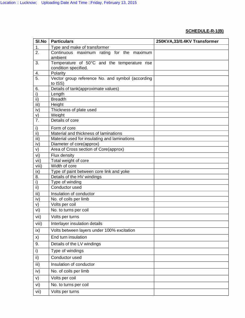
SCHEDULE-R-1(B)
Sl.No Particulars 250KVA,33/0.4KV Transformer 1. Type and make of transformer 2. Continuous maximum rating for the maximum
ambient
3. Temperature of 50°C and the temperature rise condition specified.
4. Polarity 5. Vector group reference No. and symbol (according
to ISS)
6. Details of tank(approximate values) i) Length ii) Breadth iii) Height iv) Thickness of plate used v) Weight 7. Details of core
i) Form of core ii) Material and thickness of laminations iii) Material used for insulating and laminations iv) Diameter of core(approx) v) Area of Cross section of Core(approx) vi) Flux density vii) Total weight of core viii) Width of core ix) Type of paint between core link and yoke 8. Details of the HV windings i) Type of winding ii) Conductor used iii) Insulation of conductor iv) No. of coils per limb v) Volts per coil vi) No. to turns per coil vii) Volts per turns viii) Interlayer insulation details ix) Volts between layers under 100% excitation x) End turn insulation 9. Details of the LV windings i) Type of windings ii) Conductor used iii) Insulation of conductor iv) No. of coils per limb v) Volts per coil vi) No. to turns per coil vii) Volts per turns
Location :: Lucknow; Uploading Date And Time ::Friday, February 13, 2015
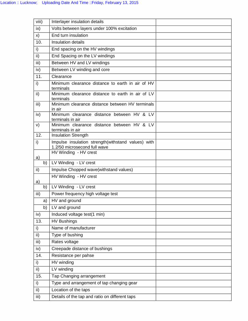
viii) Interlayer insulation details ix) Volts between layers under 100% excitation x) End turn insulation 10. Insulation details i) End spacing on the HV windings ii) End Spacing on the LV windings iii) Between HV and LV windings iv) Between LV winding and core 11. Clearance i) Minimum clearance distance to earth in air of HV
terminals
ii) Minimum clearance distance to earth in air of LV terminals
iii) Minimum clearance distance between HV terminals in air
iv) Minimum clearance distance between HV & LV terminals in air
v) Minimum clearance distance between HV & LV terminals in air
12. Insulation Strength i) Impulse insulation strength(withstand values) with
1.2/50 microsecond full wave
a)
HV Winding - HV crest
b) LV Winding - LV crest ii) Impulse Chopped wave(withstand values) a)
HV Winding - HV crest
b) LV Winding - LV crest iii) Power frequency high voltage test a) HV and ground b) LV and ground iv) Induced voltage test(1 min) 13. HV Bushings i) Name of manufacturer ii) Type of bushing iii) Rates voltage iv) Creepade distance of bushings 14. Resistance per pahse i) HV winding ii) LV winding 15. Tap Changing arrangement i) Type and arrangement of tap changing gear ii) Location of the taps iii) Details of the tap and ratio on different taps
Location :: Lucknow; Uploading Date And Time ::Friday, February 13, 2015
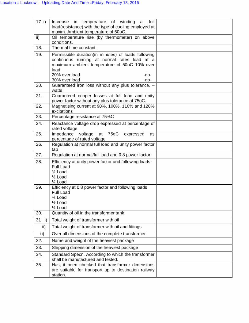
17. i) Increase in temperature of winding at full load(resistance) with the type of cooling employed at maxim. Ambient temperature of 50oC.
ii) Oil temperature rise (by thermometer) on above conditions.
18. Thermal time constant. 19. Permissible duration(in minutes) of loads following
continuous running at normal rates load at a maximum ambient temperature of 50oC 10% over load 20% over load -do- 30% over load -do-
20. Guaranteed iron loss without any plus tolerance. – watts
21. Guaranteed copper losses at full load and unity power factor without any plus tolerance at 75oC.
22. Magnetising current at 90%, 100%, 110% and 120% excitations
23. Percentage resistance at 75%C 24. Reactance voltage drop expressed at percentage of
rated voltage
25. Impedance voltage at 75oC expressed as percentage of rated voltage
26. Regulation at normal full load and unity power factor tap
27. Regulation at normal/full load and 0.8 power factor. 28. Efficiency at unity power factor and following loads
Full Load ¾ Load ½ Load ¼ Load
29. Efficiency at 0.8 power factor and following loads Full Load ¾ Load ½ Load ¼ Load
30. Quantity of oil in the transformer tank 31 i) Total weight of transformer with oil ii) Total weight of transformer with oil and fittings iii) Over all dimensions of the complete transformer 32. Name and weight of the heaviest package 33. Shipping dimension of the heaviest package 34. Standard Specn. According to which the transformer
shall be manufactured and tested.
35. Has, it been checked that transformer dimensions are suitable for transport up to destination railway station.
Location :: Lucknow; Uploading Date And Time ::Friday, February 13, 2015
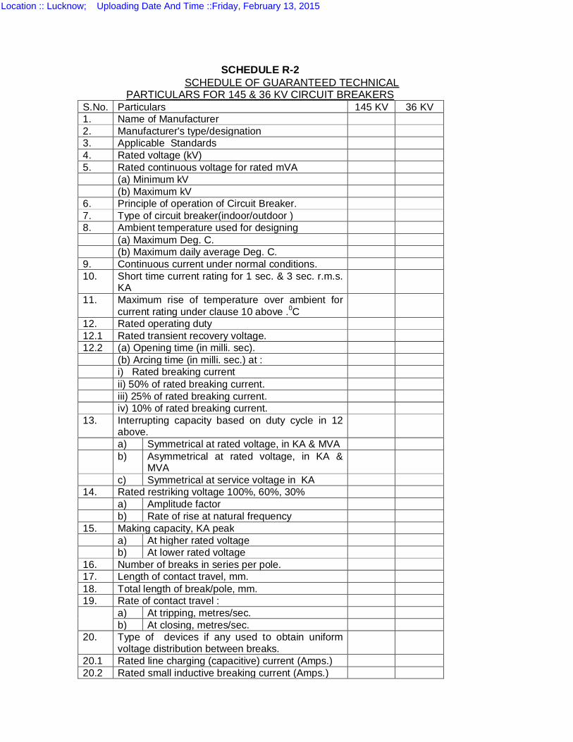
SCHEDULE R-2 SCHEDULE OF GUARANTEED TECHNICAL
PARTICULARS FOR 145 & 36 KV CIRCUIT BREAKERS S.No. Particulars 145 KV 36 KV 1. Name of Manufacturer 2. Manufacturer's type/designation 3. Applicable Standards 4. Rated voltage (kV) 5. Rated continuous voltage for rated mVA (a) Minimum kV (b) Maximum kV 6. Principle of operation of Circuit Breaker. 7. Type of circuit breaker(indoor/outdoor ) 8. Ambient temperature used for designing (a) Maximum Deg. C. (b) Maximum daily average Deg. C. 9. Continuous current under normal conditions. 10. Short time current rating for 1 sec. & 3 sec. r.m.s.
KA
11. Maximum rise of temperature over ambient for current rating under clause 10 above .0C
12. Rated operating duty 12.1 Rated transient recovery voltage. 12.2 (a) Opening time (in milli. sec). (b) Arcing time (in milli. sec.) at : i) Rated breaking current ii) 50% of rated breaking current. iii) 25% of rated breaking current. iv) 10% of rated breaking current. 13. Interrupting capacity based on duty cycle in 12
above.
a) Symmetrical at rated voltage, in KA & MVA b) Asymmetrical at rated voltage, in KA &
MVA
c) Symmetrical at service voltage in KA 14. Rated restriking voltage 100%, 60%, 30% a) Amplitude factor b) Rate of rise at natural frequency 15. Making capacity, KA peak a) At higher rated voltage b) At lower rated voltage 16. Number of breaks in series per pole. 17. Length of contact travel, mm. 18. Total length of break/pole, mm. 19. Rate of contact travel : a) At tripping, metres/sec.
b) At closing, metres/sec. 20. Type of devices if any used to obtain uniform
voltage distribution between breaks.
20.1 Rated line charging (capacitive) current (Amps.) 20.2 Rated small inductive breaking current (Amps.)
Location :: Lucknow; Uploading Date And Time ::Friday, February 13, 2015
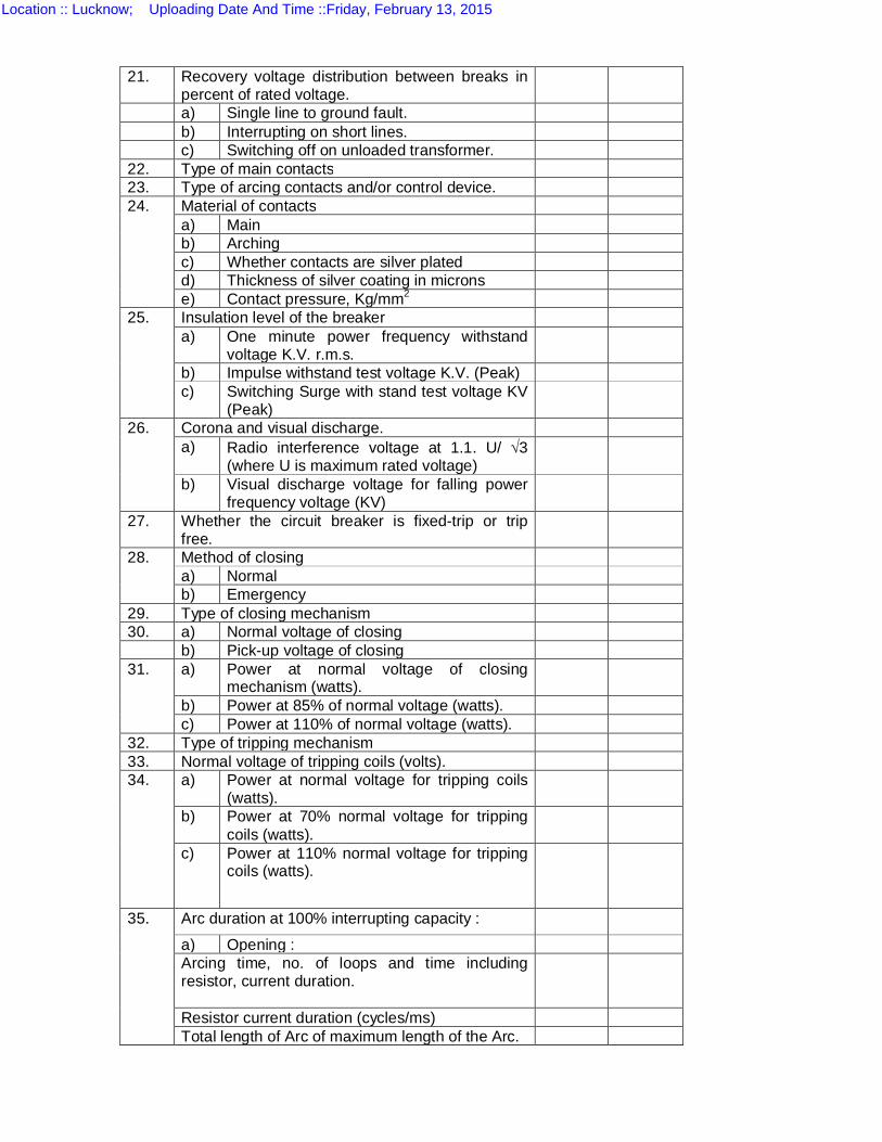
21. Recovery voltage distribution between breaks in percent of rated voltage.
a) Single line to ground fault. b) Interrupting on short lines. c) Switching off on unloaded transformer. 22. Type of main contacts 23. Type of arcing contacts and/or control device. 24. Material of contacts
a) Main b) Arching c) Whether contacts are silver plated d) Thickness of silver coating in microns e) Contact pressure, Kg/mm2
25. Insulation level of the breaker a) One minute power frequency withstand
voltage K.V. r.m.s.
b) Impulse withstand test voltage K.V. (Peak) c) Switching Surge with stand test voltage KV
(Peak)
26. Corona and visual discharge. a) Radio interference voltage at 1.1. U/ 3
(where U is maximum rated voltage)
b) Visual discharge voltage for falling power frequency voltage (KV)
27. Whether the circuit breaker is fixed-trip or trip free.
28. Method of closing a) Normal b) Emergency
29. Type of closing mechanism 30. a) Normal voltage of closing b) Pick-up voltage of closing 31. a) Power at normal voltage of closing
mechanism (watts).
b) Power at 85% of normal voltage (watts). c) Power at 110% of normal voltage (watts).
32. Type of tripping mechanism 33. Normal voltage of tripping coils (volts). 34. a) Power at normal voltage for tripping coils
(watts).
b) Power at 70% normal voltage for tripping coils (watts).
c) Power at 110% normal voltage for tripping coils (watts).
35. Arc duration at 100% interrupting capacity :
a) Opening : Arcing time, no. of loops and time including resistor, current duration.
Resistor current duration (cycles/ms) Total length of Arc of maximum length of the Arc.
Location :: Lucknow; Uploading Date And Time ::Friday, February 13, 2015
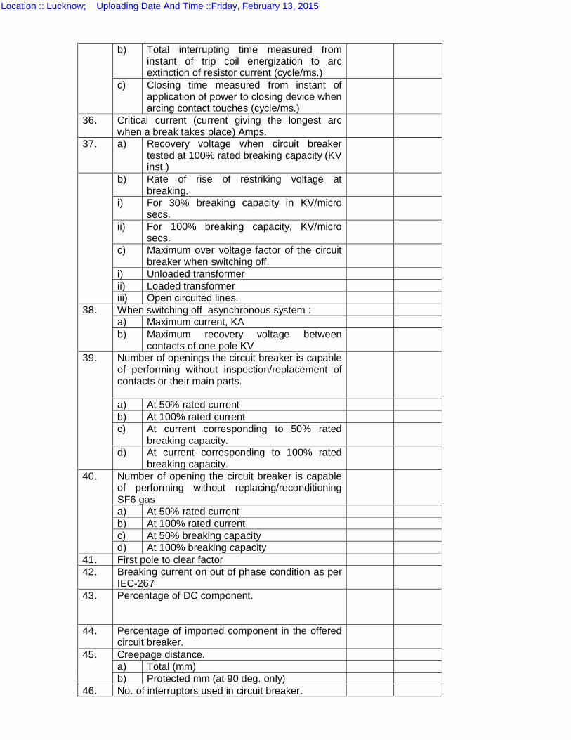
b) Total interrupting time measured from instant of trip coil energization to arc extinction of resistor current (cycle/ms.)
c) Closing time measured from instant of application of power to closing device when arcing contact touches (cycle/ms.)
36. Critical current (current giving the longest arc when a break takes place) Amps.
37. a) Recovery voltage when circuit breaker tested at 100% rated breaking capacity (KV inst.)
b) Rate of rise of restriking voltage at breaking.
i) For 30% breaking capacity in KV/micro secs.
ii) For 100% breaking capacity, KV/micro secs.
c) Maximum over voltage factor of the circuit breaker when switching off.
i) Unloaded transformer ii) Loaded transformer iii) Open circuited lines.
38. When switching off asynchronous system : a) Maximum current, KA b) Maximum recovery voltage between
contacts of one pole KV
39. Number of openings the circuit breaker is capable of performing without inspection/replacement of contacts or their main parts.
a) At 50% rated current b) At 100% rated current c) At current corresponding to 50% rated
breaking capacity.
d) At current corresponding to 100% rated breaking capacity.
40. Number of opening the circuit breaker is capable of performing without replacing/reconditioning SF6 gas
a) At 50% rated current b) At 100% rated current c) At 50% breaking capacity d) At 100% breaking capacity
41. First pole to clear factor 42. Breaking current on out of phase condition as per
IEC-267
43. Percentage of DC component.
44. Percentage of imported component in the offered circuit breaker.
45. Creepage distance. a) Total (mm) b) Protected mm (at 90 deg. only)
46. No. of interruptors used in circuit breaker.
Location :: Lucknow; Uploading Date And Time ::Friday, February 13, 2015
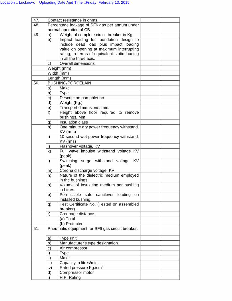
47. Contact resistance in ohms. 48. Percentage leakage of SF6 gas per annum under
normal operation of CB
49. a) Weight of complete circuit breaker in Kg. b) Impact loading for foundation design to
include dead load plus impact loading value on opening at maximum interrupting rating, in terms of equivalent static loading in all the three axis.
c) Overall dimensions Weight (mm) Width (mm) Length (mm) 50. BUSHING/PORCELAIN
a) Make b) Type c) Description pamphlet no. d) Weight (Kg.) e) Transport dimensions, mm. f) Height above floor required to remove
bushings. Mm
g) Insulation class h) One minute dry power frequency withstand,
KV (rms)
i) 10 second wet power frequency withstand, KV (rms)
j) Flashover voltage, KV k) Full wave impulse withstand voltage KV
(peak)
l) Switching surge withstand voltage KV (peak)
m) Corona discharge voltage, KV n) Nature of the dielectric medium employed
in the bushings.
o) Volume of insulating medium per bushing in Litres.
p) Permissible safe cantilever loading on installed bushing.
q) Test Certificate No. (Tested on assembled breaker).
r) Creepage distance. (a) Total (b) Protected
51. Pneumatic equipment for SF6 gas circuit breaker.
a) Type unit b) Manufacturer's type designation. c) Air compressor i) Type ii) Make iii) Capacity in litres/min. iv) Rated pressure Kg./cm2 d) Compressor motor i) H.P. Rating
Location :: Lucknow; Uploading Date And Time ::Friday, February 13, 2015
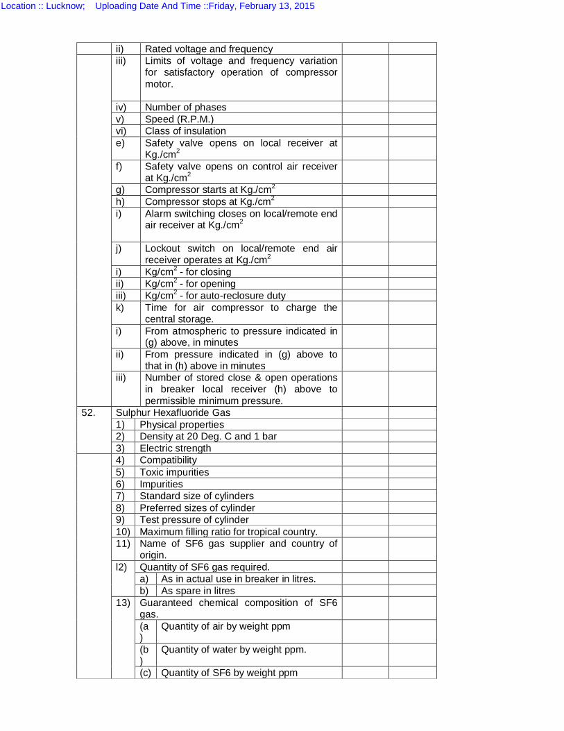
ii) Rated voltage and frequency iii) Limits of voltage and frequency variation
for satisfactory operation of compressor motor.
iv) Number of phases v) Speed (R.P.M.) vi) Class of insulation e) Safety valve opens on local receiver at
Kg./cm2
f) Safety valve opens on control air receiver at Kg./cm2
g) Compressor starts at Kg./cm2 h) Compressor stops at Kg./cm2 i) Alarm switching closes on local/remote end
air receiver at Kg./cm2
j) Lockout switch on local/remote end air receiver operates at Kg./cm2
i) Kg/cm2 - for closing ii) Kg/cm2 - for opening iii) Kg/cm2 - for auto-reclosure duty k) Time for air compressor to charge the
central storage.
i) From atmospheric to pressure indicated in (g) above, in minutes
ii) From pressure indicated in (g) above to that in (h) above in minutes
iii) Number of stored close & open operations in breaker local receiver (h) above to permissible minimum pressure.
52. Sulphur Hexafluoride Gas 1) Physical properties 2) Density at 20 Deg. C and 1 bar 3) Electric strength
4) Compatibility 5) Toxic impurities 6) Impurities 7) Standard size of cylinders 8) Preferred sizes of cylinder 9) Test pressure of cylinder 10) Maximum filling ratio for tropical country. 11) Name of SF6 gas supplier and country of
origin.
l2) Quantity of SF6 gas required. a) As in actual use in breaker in litres. b) As spare in litres
13) Guaranteed chemical composition of SF6 gas.
(a)
Quantity of air by weight ppm
(b)
Quantity of water by weight ppm.
(c) Quantity of SF6 by weight ppm
Location :: Lucknow; Uploading Date And Time ::Friday, February 13, 2015
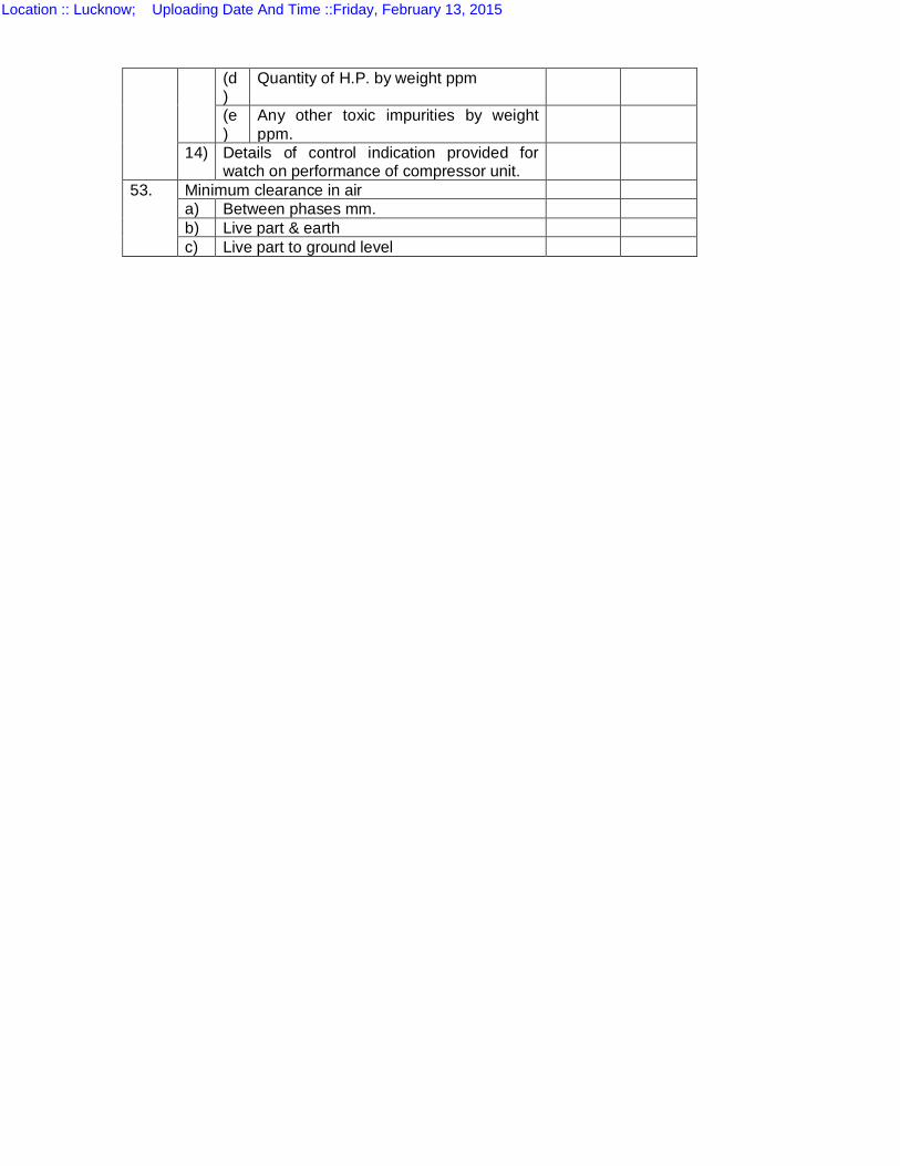
(d)
Quantity of H.P. by weight ppm
(e)
Any other toxic impurities by weight ppm.
14) Details of control indication provided for watch on performance of compressor unit.
53. Minimum clearance in air a) Between phases mm. b) Live part & earth c) Live part to ground level
Location :: Lucknow; Uploading Date And Time ::Friday, February 13, 2015
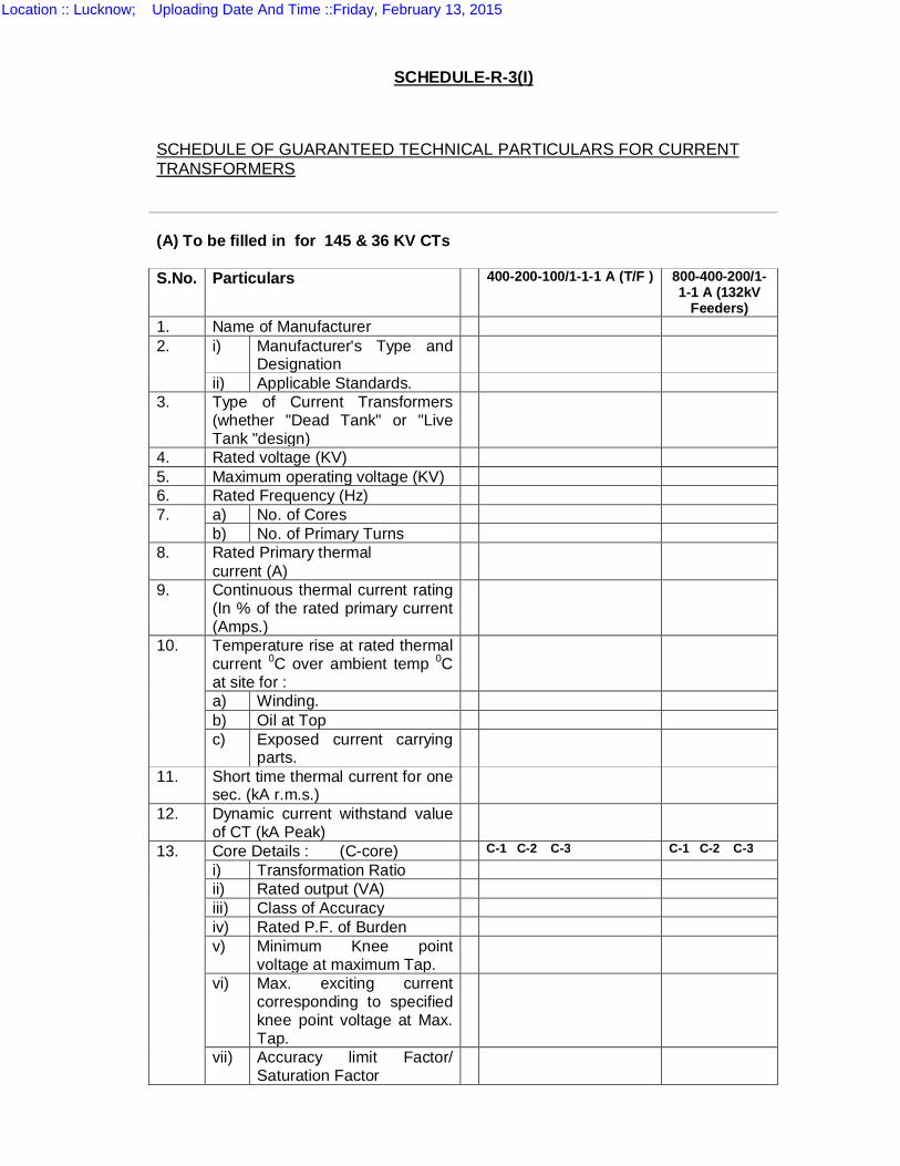
SCHEDULE-R-3(I)
SCHEDULE OF GUARANTEED TECHNICAL PARTICULARS FOR CURRENT TRANSFORMERS
(A) To be filled in for 145 & 36 KV CTs S.No. Particulars 400-200-100/1-1-1 A (T/F ) 800-400-200/1-
1-1 A (132kV Feeders)
1. Name of Manufacturer 2. i) Manufacturer's Type and
Designation
ii) Applicable Standards. 3. Type of Current Transformers
(whether "Dead Tank" or "Live Tank "design)
4. Rated voltage (KV) 5. Maximum operating voltage (KV) 6. Rated Frequency (Hz) 7. a) No. of Cores
b) No. of Primary Turns 8. Rated Primary thermal
current (A)
9. Continuous thermal current rating (In % of the rated primary current (Amps.)
10. Temperature rise at rated thermal current 0C over ambient temp 0C at site for :
a) Winding. b) Oil at Top c) Exposed current carrying
parts.
11. Short time thermal current for one sec. (kA r.m.s.)
12. Dynamic current withstand value of CT (kA Peak)
13. Core Details : (C-core) C-1 C-2 C-3 C-1 C-2 C-3
i) Transformation Ratio ii) Rated output (VA) iii) Class of Accuracy iv) Rated P.F. of Burden v) Minimum Knee point
voltage at maximum Tap.
vi) Max. exciting current corresponding to specified knee point voltage at Max. Tap.
vii) Accuracy limit Factor/ Saturation Factor
Location :: Lucknow; Uploading Date And Time ::Friday, February 13, 2015
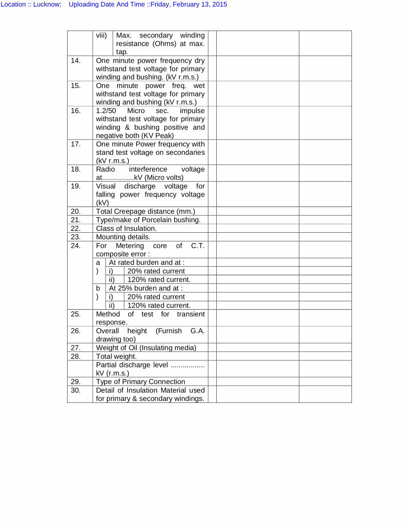
viii) Max. secondary winding resistance (Ohms) at max. tap.
14. One minute power frequency dry withstand test voltage for primary winding and bushing. (kV r.m.s.)
15. One minute power freq. wet withstand test voltage for primary winding and bushing (kV r.m.s.)
16. 1.2/50 Micro sec. impulse withstand test voltage for primary winding & bushing positive and negative both (KV Peak)
17. One minute Power frequency with stand test voltage on secondaries (kV r.m.s.)
18. Radio interference voltage at................kV (Micro volts)
19. Visual discharge voltage for falling power frequency voltage (kV)
20. Total Creepage distance (mm.) 21. Type/make of Porcelain bushing. 22. Class of Insulation. 23. Mounting details. 24. For Metering core of C.T.
composite error :
a)
At rated burden and at : i) 20% rated current ii) 120% rated current.
b)
At 25% burden and at : i) 20% rated current ii) 120% rated current.
25. Method of test for transient response.
26. Overall height (Furnish G.A. drawing too)
27. Weight of Oil (Insulating media) 28. Total weight. Partial discharge level .................
kV (r.m.s.)
29. Type of Primary Connection 30. Detail of Insulation Material used
for primary & secondary windings.
Location :: Lucknow; Uploading Date And Time ::Friday, February 13, 2015
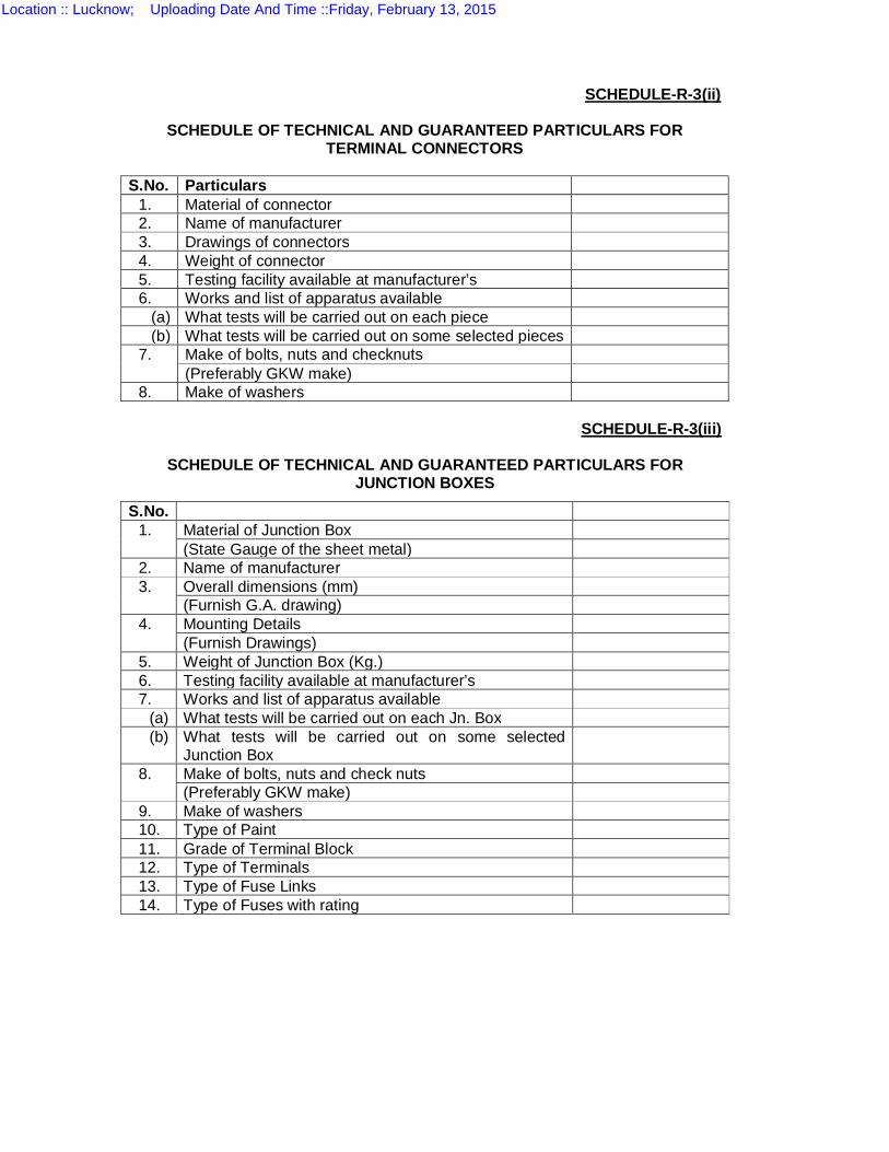
SCHEDULE-R-3(ii)
SCHEDULE OF TECHNICAL AND GUARANTEED PARTICULARS FOR
TERMINAL CONNECTORS S.No. Particulars
1. Material of connector 2. Name of manufacturer 3. Drawings of connectors 4. Weight of connector 5. Testing facility available at manufacturer’s 6. Works and list of apparatus available
(a) What tests will be carried out on each piece (b) What tests will be carried out on some selected pieces
7. Make of bolts, nuts and checknuts (Preferably GKW make)
8. Make of washers
SCHEDULE-R-3(iii)
SCHEDULE OF TECHNICAL AND GUARANTEED PARTICULARS FOR JUNCTION BOXES
S.No. 1. Material of Junction Box
(State Gauge of the sheet metal) 2. Name of manufacturer 3. Overall dimensions (mm)
(Furnish G.A. drawing) 4. Mounting Details
(Furnish Drawings) 5. Weight of Junction Box (Kg.) 6. Testing facility available at manufacturer’s 7. Works and list of apparatus available
(a) What tests will be carried out on each Jn. Box (b) What tests will be carried out on some selected
Junction Box
8. Make of bolts, nuts and check nuts (Preferably GKW make)
9. Make of washers 10. Type of Paint 11. Grade of Terminal Block 12. Type of Terminals 13. Type of Fuse Links 14. Type of Fuses with rating
Location :: Lucknow; Uploading Date And Time ::Friday, February 13, 2015
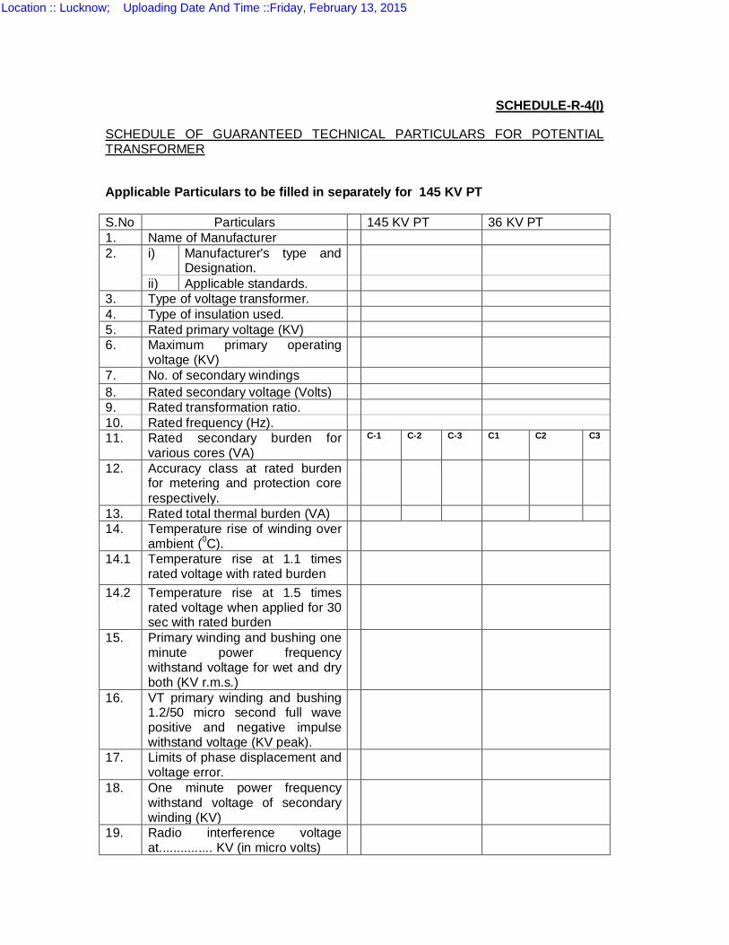
SCHEDULE-R-4(I)
SCHEDULE OF GUARANTEED TECHNICAL PARTICULARS FOR POTENTIAL TRANSFORMER
Applicable Particulars to be filled in separately for 145 KV PT S.No Particulars 145 KV PT 36 KV PT 1. Name of Manufacturer 2. i) Manufacturer's type and
Designation.
ii) Applicable standards. 3. Type of voltage transformer. 4. Type of insulation used. 5. Rated primary voltage (KV) 6. Maximum primary operating
voltage (KV)
7. No. of secondary windings 8. Rated secondary voltage (Volts) 9. Rated transformation ratio. 10. Rated frequency (Hz). 11. Rated secondary burden for
various cores (VA) C-1 C-2 C-3 C1 C2 C3
12. Accuracy class at rated burden for metering and protection core respectively.
13. Rated total thermal burden (VA) 14. Temperature rise of winding over
ambient (0C).
14.1 Temperature rise at 1.1 times rated voltage with rated burden
14.2 Temperature rise at 1.5 times rated voltage when applied for 30 sec with rated burden
15. Primary winding and bushing one minute power frequency withstand voltage for wet and dry both (KV r.m.s.)
16. VT primary winding and bushing 1.2/50 micro second full wave positive and negative impulse withstand voltage (KV peak).
17. Limits of phase displacement and voltage error.
18. One minute power frequency withstand voltage of secondary winding (KV)
19. Radio interference voltage at............... KV (in micro volts)
Location :: Lucknow; Uploading Date And Time ::Friday, February 13, 2015
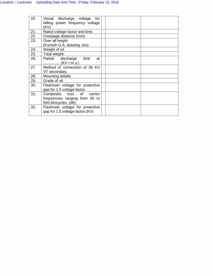
20. Visual discharge voltage for falling power frequency voltage (KV)
21. Rated voltage factor and time. 22. Creepage distance (mm) 23. Over all height
(Furnish G.A. drawing. too)
24. Weight of oil. 25. Total weight. 26. Partial discharge limit at
................ (KV r.m.s.)
27. Method of connection of 36 KV VT secondary.
28. Mounting details 29. Grade of oil. 30. Flashover voltage for protective
gap for 1.5 voltage factor.
31. Composite loss of carrier frequencies ranging from 50 to 500 kilocycles. (dB)
32. Flashover voltage for protective gap for 1.5 voltage factor.(KV)
Location :: Lucknow; Uploading Date And Time ::Friday, February 13, 2015
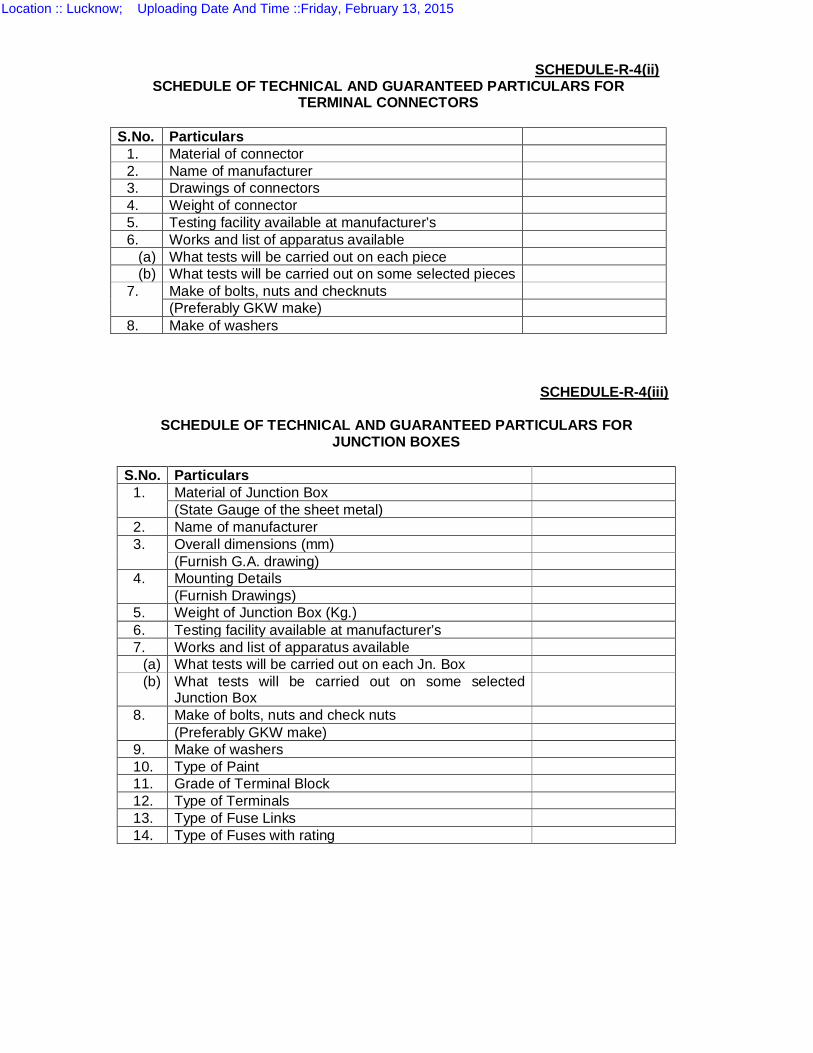
SCHEDULE-R-4(ii) SCHEDULE OF TECHNICAL AND GUARANTEED PARTICULARS FOR
TERMINAL CONNECTORS S.No. Particulars
1. Material of connector 2. Name of manufacturer 3. Drawings of connectors 4. Weight of connector 5. Testing facility available at manufacturer’s 6. Works and list of apparatus available
(a) What tests will be carried out on each piece (b) What tests will be carried out on some selected pieces
7. Make of bolts, nuts and checknuts (Preferably GKW make)
8. Make of washers
SCHEDULE-R-4(iii)
SCHEDULE OF TECHNICAL AND GUARANTEED PARTICULARS FOR JUNCTION BOXES
S.No. Particulars
1. Material of Junction Box (State Gauge of the sheet metal)
2. Name of manufacturer 3. Overall dimensions (mm)
(Furnish G.A. drawing) 4. Mounting Details
(Furnish Drawings) 5. Weight of Junction Box (Kg.) 6. Testing facility available at manufacturer’s 7. Works and list of apparatus available
(a) What tests will be carried out on each Jn. Box (b) What tests will be carried out on some selected
Junction Box
8. Make of bolts, nuts and check nuts (Preferably GKW make)
9. Make of washers 10. Type of Paint 11. Grade of Terminal Block 12. Type of Terminals 13. Type of Fuse Links 14. Type of Fuses with rating
Location :: Lucknow; Uploading Date And Time ::Friday, February 13, 2015
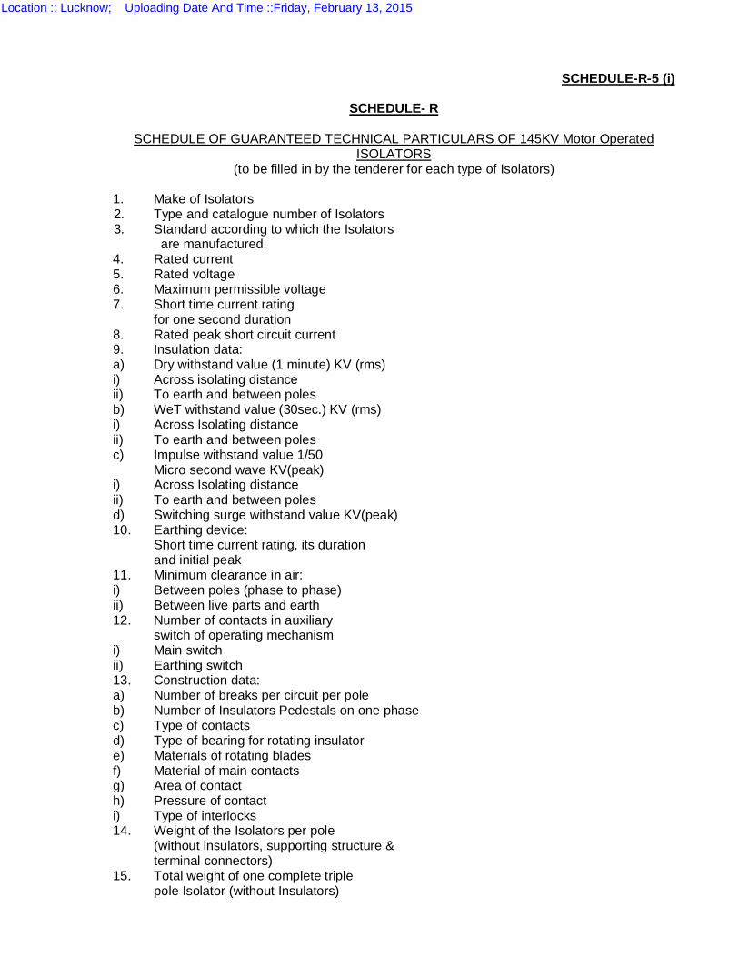
SCHEDULE-R-5 (i)
SCHEDULE- R
SCHEDULE OF GUARANTEED TECHNICAL PARTICULARS OF 145KV Motor Operated
ISOLATORS (to be filled in by the tenderer for each type of Isolators)
1. Make of Isolators
2. Type and catalogue number of Isolators 3. Standard according to which the Isolators are manufactured.
4. Rated current 5. Rated voltage 6. Maximum permissible voltage 7. Short time current rating for one second duration 8. Rated peak short circuit current 9. Insulation data: a) Dry withstand value (1 minute) KV (rms) i) Across isolating distance ii) To earth and between poles b) WeT withstand value (30sec.) KV (rms) i) Across Isolating distance ii) To earth and between poles c) Impulse withstand value 1/50 Micro second wave KV(peak) i) Across Isolating distance ii) To earth and between poles d) Switching surge withstand value KV(peak) 10. Earthing device: Short time current rating, its duration and initial peak 11. Minimum clearance in air: i) Between poles (phase to phase) ii) Between live parts and earth 12. Number of contacts in auxiliary switch of operating mechanism i) Main switch ii) Earthing switch 13. Construction data: a) Number of breaks per circuit per pole b) Number of Insulators Pedestals on one phase c) Type of contacts d) Type of bearing for rotating insulator e) Materials of rotating blades f) Material of main contacts g) Area of contact h) Pressure of contact i) Type of interlocks 14. Weight of the Isolators per pole (without insulators, supporting structure & terminal connectors) 15. Total weight of one complete triple pole Isolator (without Insulators)
Location :: Lucknow; Uploading Date And Time ::Friday, February 13, 2015
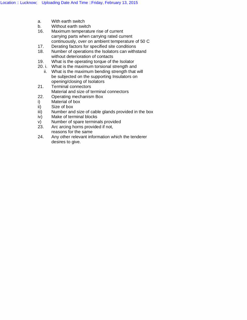
a. With earth switch b. Without earth switch 16. Maximum temperature rise of current carrying parts when carrying rated current continuously, over on ambient temperature of 50 C 17. Derating factors for specified site conditions 18. Number of operations the Isolators can withstand without deterioration of contacts 19. What is the operating torque of the Isolator 20. i. What is the maximum torsional strength and ii. What is the maximum bending strength that will be subjected on the supporting Insulators on opening/closing of Isolators 21. Terminal connectors Material and size of terminal connectors 22. Operating mechanism Box i) Material of box ii) Size of box iii) Number and size of cable glands provided in the box iv) Make of terminal blocks v) Number of spare terminals provided 23. Arc arcing horns provided if not, reasons for the same 24. Any other relevant information which the tenderer desires to give.
Location :: Lucknow; Uploading Date And Time ::Friday, February 13, 2015
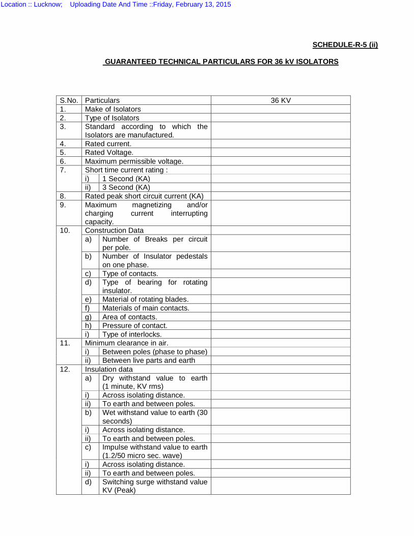
SCHEDULE-R-5 (ii)
GUARANTEED TECHNICAL PARTICULARS FOR 36 kV ISOLATORS
S.No. Particulars 36 KV 1. Make of Isolators 2. Type of Isolators 3. Standard according to which the
Isolators are manufactured.
4. Rated current. 5. Rated Voltage. 6. Maximum permissible voltage. 7. Short time current rating :
i) 1 Second (KA) ii) 3 Second (KA)
8. Rated peak short circuit current (KA) 9. Maximum magnetizing and/or
charging current interrupting capacity.
10. Construction Data a) Number of Breaks per circuit
per pole.
b) Number of Insulator pedestals on one phase.
c) Type of contacts. d) Type of bearing for rotating
insulator.
e) Material of rotating blades. f) Materials of main contacts. g) Area of contacts. h) Pressure of contact. i) Type of interlocks.
11. Minimum clearance in air. i) Between poles (phase to phase) ii) Between live parts and earth
12. Insulation data a) Dry withstand value to earth
(1 minute, KV rms)
i) Across isolating distance. ii) To earth and between poles. b) Wet withstand value to earth (30
seconds)
i) Across isolating distance. ii) To earth and between poles. c) Impulse withstand value to earth
(1.2/50 micro sec. wave)
i) Across isolating distance. ii) To earth and between poles. d) Switching surge withstand value
KV (Peak)
Location :: Lucknow; Uploading Date And Time ::Friday, February 13, 2015
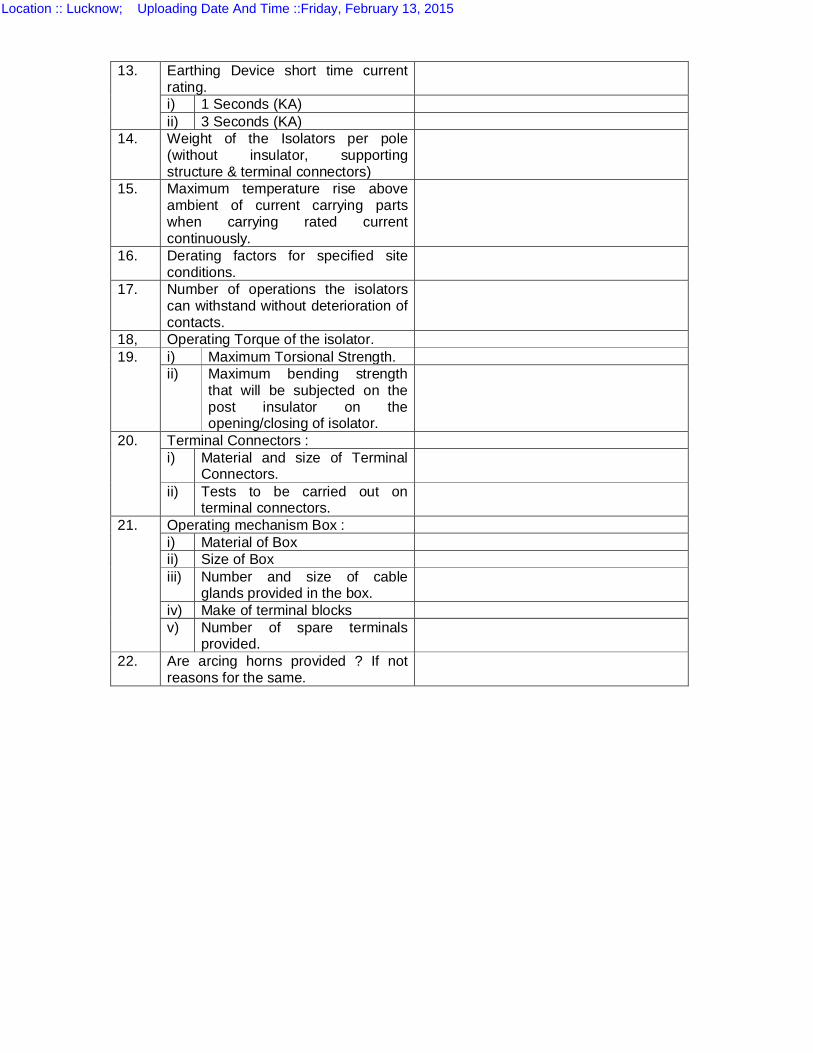
13. Earthing Device short time current rating.
i) 1 Seconds (KA) ii) 3 Seconds (KA)
14. Weight of the Isolators per pole (without insulator, supporting structure & terminal connectors)
15. Maximum temperature rise above ambient of current carrying parts when carrying rated current continuously.
16. Derating factors for specified site conditions.
17. Number of operations the isolators can withstand without deterioration of contacts.
18, Operating Torque of the isolator. 19. i) Maximum Torsional Strength.
ii) Maximum bending strength that will be subjected on the post insulator on the opening/closing of isolator.
20. Terminal Connectors : i) Material and size of Terminal
Connectors.
ii) Tests to be carried out on terminal connectors.
21. Operating mechanism Box : i) Material of Box ii) Size of Box iii) Number and size of cable
glands provided in the box.
iv) Make of terminal blocks v) Number of spare terminals
provided.
22. Are arcing horns provided ? If not reasons for the same.
Location :: Lucknow; Uploading Date And Time ::Friday, February 13, 2015
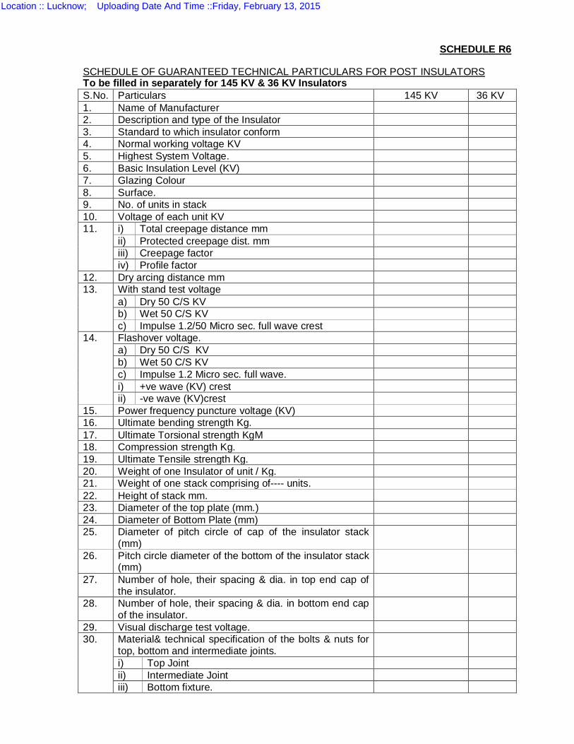
SCHEDULE R6
SCHEDULE OF GUARANTEED TECHNICAL PARTICULARS FOR POST INSULATORS To be filled in separately for 145 KV & 36 KV Insulators S.No. Particulars 145 KV 36 KV 1. Name of Manufacturer 2. Description and type of the Insulator 3. Standard to which insulator conform 4. Normal working voltage KV 5. Highest System Voltage. 6. Basic Insulation Level (KV) 7. Glazing Colour 8. Surface. 9. No. of units in stack 10. Voltage of each unit KV 11. i) Total creepage distance mm
ii) Protected creepage dist. mm iii) Creepage factor iv) Profile factor
12. Dry arcing distance mm 13. With stand test voltage
a) Dry 50 C/S KV b) Wet 50 C/S KV c) Impulse 1.2/50 Micro sec. full wave crest
14. Flashover voltage. a) Dry 50 C/S KV b) Wet 50 C/S KV c) Impulse 1.2 Micro sec. full wave. i) +ve wave (KV) crest ii) -ve wave (KV)crest
15. Power frequency puncture voltage (KV) 16. Ultimate bending strength Kg. 17. Ultimate Torsional strength KgM 18. Compression strength Kg. 19. Ultimate Tensile strength Kg. 20. Weight of one Insulator of unit / Kg. 21. Weight of one stack comprising of---- units. 22. Height of stack mm. 23. Diameter of the top plate (mm.) 24. Diameter of Bottom Plate (mm) 25. Diameter of pitch circle of cap of the insulator stack
(mm)
26. Pitch circle diameter of the bottom of the insulator stack (mm)
27. Number of hole, their spacing & dia. in top end cap of the insulator.
28. Number of hole, their spacing & dia. in bottom end cap of the insulator.
29. Visual discharge test voltage. 30. Material& technical specification of the bolts & nuts for
top, bottom and intermediate joints.
i) Top Joint ii) Intermediate Joint iii) Bottom fixture.
Location :: Lucknow; Uploading Date And Time ::Friday, February 13, 2015
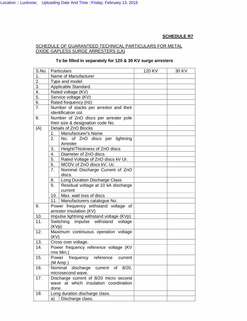
SCHEDULE R7
SCHEDULE OF GUARANTEED TECHNICAL PARTICULARS FOR METAL OXIDE GAPLESS SURGE ARRESTERS (LA)
To be filled in separately for 120 & 30 KV surge arresters S.No. Particulars 120 KV 30 KV 1. Name of Manufacturer 2. Type and model 3. Applicable Standard. 4. Rated voltage (KV) 5. Service voltage (KV) 6. Rated frequency (Hz) 7. Number of stacks per arrestor and their
identification col.
8. Number of ZnO discs per arrester pole their size & designation code No.
(A) Details of ZnO Blocks 1. Manufacturer's Name 2. No. of ZnO discs per lightning
Arrester
3. Height/Thickness of ZnO discs 4. Diameter of ZnO discs 5. Rated Voltage of ZnO discs kV Ur. 6. MCOV of ZnO discs kV, Uc 7. Nominal Discharge Current of ZnO
discs.
8. Long Duration Discharge Class 9. Residual voltage at 10 kA discharge
current
10. Max. watt loss of discs 11. Manufacturers catalogue No.
9. Power frequency withstand voltage of arrester insulation (KV)
10. Impulse lightning withstand voltage (KVp) 11. Switching impulse withstand voltage
(KVp)
12. Maximum continuous operation voltage (KV)
13. Cross over voltage. 14. Power frequency reference voltage (KV
rms Min.)
15. Power frequency reference current (M Amp.)
16. Nominal discharge current of 8/20, microsecond wave.
17. Discharge current of 8/20 micro second wave at which insulation coordination done.
18. Long duration discharge class. a) Discharge class.
Location :: Lucknow; Uploading Date And Time ::Friday, February 13, 2015
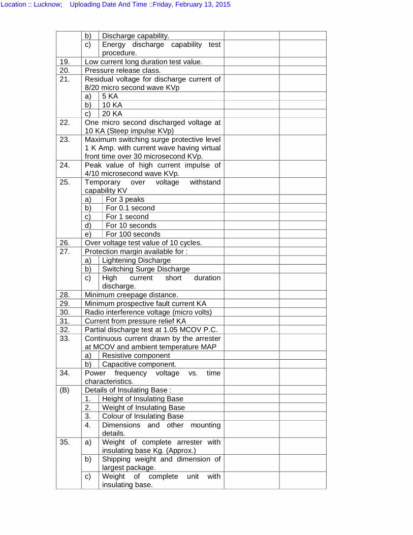
b) Discharge capability. c) Energy discharge capability test
procedure.
19. Low current long duration test value. 20. Pressure release class. 21. Residual voltage for discharge current of
8/20 micro second wave KVp
a) 5 KA b) 10 KA c) 20 KA
22. One micro second discharged voltage at 10 KA (Steep impulse KVp)
23. Maximum switching surge protective level 1 K Amp. with current wave having virtual front time over 30 microsecond KVp.
24. Peak value of high current impulse of 4/10 microsecond wave KVp.
25. Temporary over voltage withstand capability KV
a) For 3 peaks b) For 0.1 second c) For 1 second d) For 10 seconds e) For 100 seconds
26. Over voltage test value of 10 cycles. 27. Protection margin available for :
a) Lightening Discharge b) Switching Surge Discharge c) High current short duration
discharge.
28. Minimum creepage distance. 29. Minimum prospective fault current KA 30. Radio interference voltage (micro volts) 31. Current from pressure relief KA 32. Partial discharge test at 1.05 MCOV P.C. 33. Continuous current drawn by the arrester
at MCOV and ambient temperature MAP
a) Resistive component b) Capacitive component.
34. Power frequency voltage vs. time characteristics.
(B) Details of Insulating Base : 1. Height of Insulating Base 2. Weight of Insulating Base 3. Colour of Insulating Base 4. Dimensions and other mounting
details.
35. a) Weight of complete arrester with insulating base Kg. (Approx.)
b) Shipping weight and dimension of largest package.
c) Weight of complete unit with insulating base.
Location :: Lucknow; Uploading Date And Time ::Friday, February 13, 2015
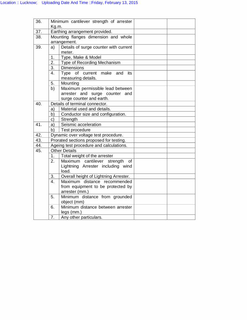
36. Minimum cantilever strength of arrester Kg.m.
37. Earthing arrangement provided. 38. Mounting flanges dimension and whole
arrangement.
39. a) Details of surge counter with current meter.
1. Type, Make & Model 2. Type of Recording Mechanism 3. Dimensions 4. Type of current make and its
measuring details.
5. Mounting b) Maximum permissible lead between
arrester and surge counter and surge counter and earth.
40. Details of terminal connector. a) Material used and details. b) Conductor size and configuration. c) Strength
41. a) Seismic acceleration b) Test procedure
42. Dynamic over voltage test procedure. 43. Prorated sections proposed for testing. 44. Ageing test procedure and calculations. 45. Other Details
1. Total weight of the arrester 2. Maximum cantilever strength of
Lightning Arrester including wind load.
3. Overall height of Lightning Arrester. 4. Maximum distance recommended
from equipment to be protected by arrester (mm.)
5. Minimum distance from grounded object (mm)
6. Minimum distance between arrester legs (mm.)
7. Any other particulars.
Location :: Lucknow; Uploading Date And Time ::Friday, February 13, 2015

GUARANTEED TECHNICAL PARTICULARS
2.1 SCHEDULE-R-8(i)
GUARANTEED TECHNICAL PARTICULARS FOR 132 KV FEEDER BAY
Sl. No
Item Description Qty ( No)
MAKE TYPE
1 Simplex Panel, Panel Dimension : 800(W) x 800(D) x 2315(H), Powder coated
Metering: 2 ABT Compliant Trivector meter, polyphase
meter, 3 Phase, 4 wire, 3 element, suitable for unbalanced loads, Accuracy: 0.2, with KWH (Import & Export), KVARH (Import & Export), Lead & Lagging VAR SCADA Compatible and with standard parameter.
3 Test terminal block Control & Indication 4 Control Switch for CB Type: Spring Return with
LMD, Pistol Grip Handle, 3 Pos, 10Ways
Protection 5 Numerical Bay Control unit with MIMIC with the
following functions: - Synchrocheck & Energising Check(RSYN,25) - Monitoring - Metering - Tripping Logic(PTRC,94) - Disturbance Recorder(RDRE) - Event Recorder (RDRE)
Location :: Lucknow; Uploading Date And Time ::Friday, February 13, 2015
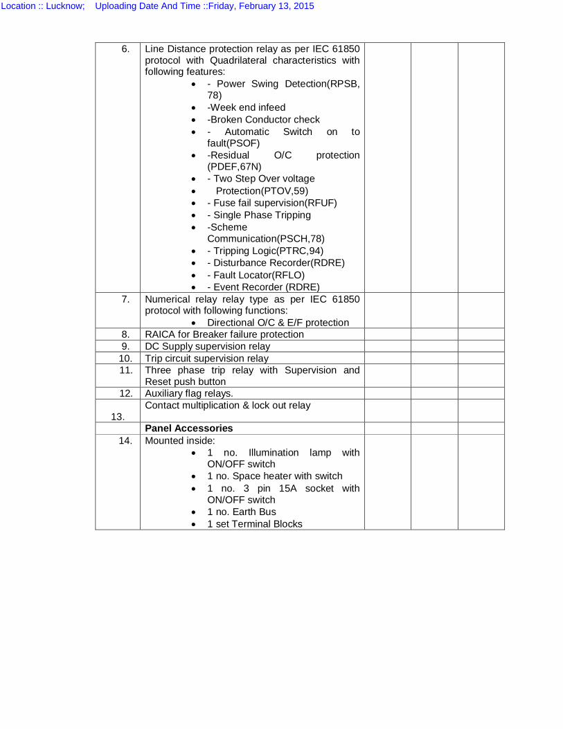
6. Line Distance protection relay as per IEC 61850 protocol with Quadrilateral characteristics with following features:
- Power Swing Detection(RPSB, 78)
-Week end infeed -Broken Conductor check - Automatic Switch on to
fault(PSOF) -Residual O/C protection
(PDEF,67N) - Two Step Over voltage Protection(PTOV,59) - Fuse fail supervision(RFUF) - Single Phase Tripping -Scheme
Communication(PSCH,78) - Tripping Logic(PTRC,94) - Disturbance Recorder(RDRE) - Fault Locator(RFLO) - Event Recorder (RDRE)
7. Numerical relay relay type as per IEC 61850 protocol with following functions:
Directional O/C & E/F protection
8. RAICA for Breaker failure protection 9. DC Supply supervision relay
10. Trip circuit supervision relay 11. Three phase trip relay with Supervision and
Reset push button
12. Auxiliary flag relays.
13. Contact multiplication & lock out relay
Panel Accessories 14. Mounted inside:
1 no. Illumination lamp with ON/OFF switch
1 no. Space heater with switch 1 no. 3 pin 15A socket with
ON/OFF switch 1 no. Earth Bus 1 set Terminal Blocks
Location :: Lucknow; Uploading Date And Time ::Friday, February 13, 2015
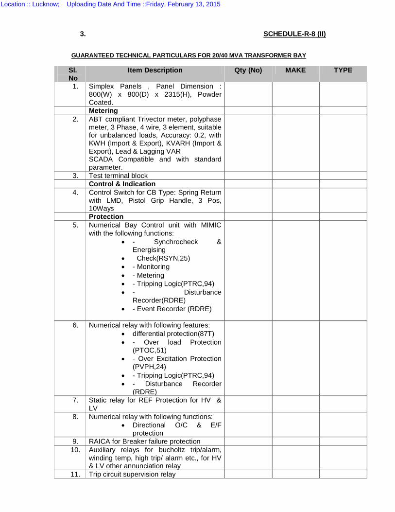
3. SCHEDULE-R-8 (II)
GUARANTEED TECHNICAL PARTICULARS FOR 20/40 MVA TRANSFORMER BAY
Sl. No
Item Description Qty (No) MAKE TYPE
1.
Simplex Panels , Panel Dimension : 800(W) x 800(D) x 2315(H), Powder Coated.
Metering 2. ABT compliant Trivector meter, polyphase
meter, 3 Phase, 4 wire, 3 element, suitable for unbalanced loads, Accuracy: 0.2, with KWH (Import & Export), KVARH (Import & Export), Lead & Lagging VAR SCADA Compatible and with standard parameter.
3. Test terminal block Control & Indication 4. Control Switch for CB Type: Spring Return
with LMD, Pistol Grip Handle, 3 Pos, 10Ways
Protection 5. Numerical Bay Control unit with MIMIC
with the following functions: - Synchrocheck &
Energising Check(RSYN,25) - Monitoring - Metering - Tripping Logic(PTRC,94) - Disturbance
Recorder(RDRE) - Event Recorder (RDRE)
6. Numerical relay with following features: differential protection(87T) - Over load Protection
(PTOC,51) - Over Excitation Protection
(PVPH,24) - Tripping Logic(PTRC,94) - Disturbance Recorder
(RDRE)
7. Static relay for REF Protection for HV & LV
8. Numerical relay with following functions: Directional O/C & E/F
protection
9. RAICA for Breaker failure protection 10. Auxiliary relays for bucholtz trip/alarm,
winding temp, high trip/ alarm etc., for HV & LV other annunciation relay
11. Trip circuit supervision relay
Location :: Lucknow; Uploading Date And Time ::Friday, February 13, 2015

12. DC supply supervision relay 13. High Speed trip relays
Panel Accessories 14. Mounted inside:
1 no. Illumination lamp with ON/OFF switch
1 no. Space heater with switch
1 no. 3 pin 15A socket with ON/OFF switch
1 no. Earth Bus 1 set Terminal Blocks
Location :: Lucknow; Uploading Date And Time ::Friday, February 13, 2015
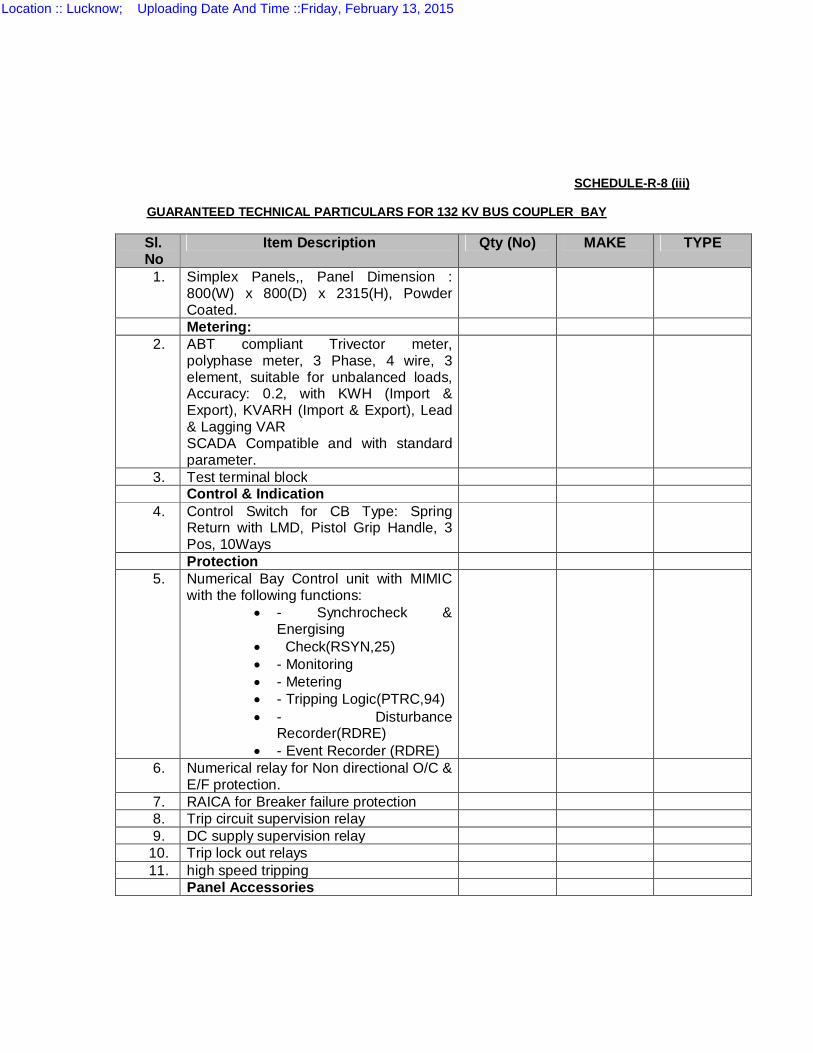
SCHEDULE-R-8 (iii) GUARANTEED TECHNICAL PARTICULARS FOR 132 KV BUS COUPLER BAY
Sl. No
Item Description Qty (No) MAKE TYPE
1. Simplex Panels,, Panel Dimension : 800(W) x 800(D) x 2315(H), Powder Coated.
Metering: 2. ABT compliant Trivector meter,
polyphase meter, 3 Phase, 4 wire, 3 element, suitable for unbalanced loads, Accuracy: 0.2, with KWH (Import & Export), KVARH (Import & Export), Lead & Lagging VAR SCADA Compatible and with standard parameter.
3. Test terminal block Control & Indication 4. Control Switch for CB Type: Spring
Return with LMD, Pistol Grip Handle, 3 Pos, 10Ways
Protection 5. Numerical Bay Control unit with MIMIC
with the following functions: - Synchrocheck &
Energising Check(RSYN,25) - Monitoring - Metering - Tripping Logic(PTRC,94) - Disturbance
Recorder(RDRE) - Event Recorder (RDRE)
6. Numerical relay for Non directional O/C & E/F protection.
7. RAICA for Breaker failure protection 8. Trip circuit supervision relay 9. DC supply supervision relay
10. Trip lock out relays 11. high speed tripping
Panel Accessories
Location :: Lucknow; Uploading Date And Time ::Friday, February 13, 2015

12. Mounted inside: 1 no. Illumination lamp with
ON/OFF switch 1 no. Space heater with
switch 1 no. 3 pin 15A socket with
ON/OFF switch 1 no. Earth Bus 1 set Terminal Blocks
Location :: Lucknow; Uploading Date And Time ::Friday, February 13, 2015
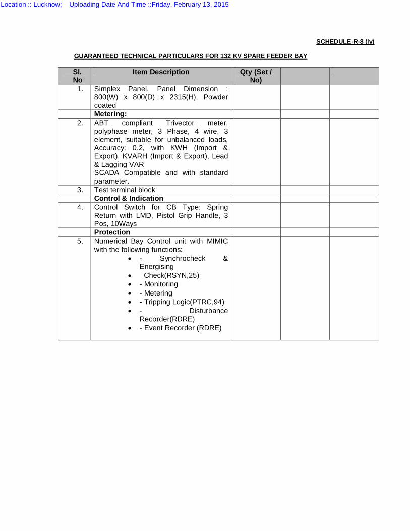
SCHEDULE-R-8 (iv)
GUARANTEED TECHNICAL PARTICULARS FOR 132 KV SPARE FEEDER BAY
Sl. No
Item Description Qty (Set / No)
1. Simplex Panel, Panel Dimension : 800(W) x 800(D) x 2315(H), Powder coated
Metering: 2. ABT compliant Trivector meter,
polyphase meter, 3 Phase, 4 wire, 3 element, suitable for unbalanced loads, Accuracy: 0.2, with KWH (Import & Export), KVARH (Import & Export), Lead & Lagging VAR SCADA Compatible and with standard parameter.
3. Test terminal block Control & Indication 4. Control Switch for CB Type: Spring
Return with LMD, Pistol Grip Handle, 3 Pos, 10Ways
Protection 5. Numerical Bay Control unit with MIMIC
with the following functions: - Synchrocheck &
Energising Check(RSYN,25) - Monitoring - Metering - Tripping Logic(PTRC,94) - Disturbance
Recorder(RDRE) - Event Recorder (RDRE)
Location :: Lucknow; Uploading Date And Time ::Friday, February 13, 2015
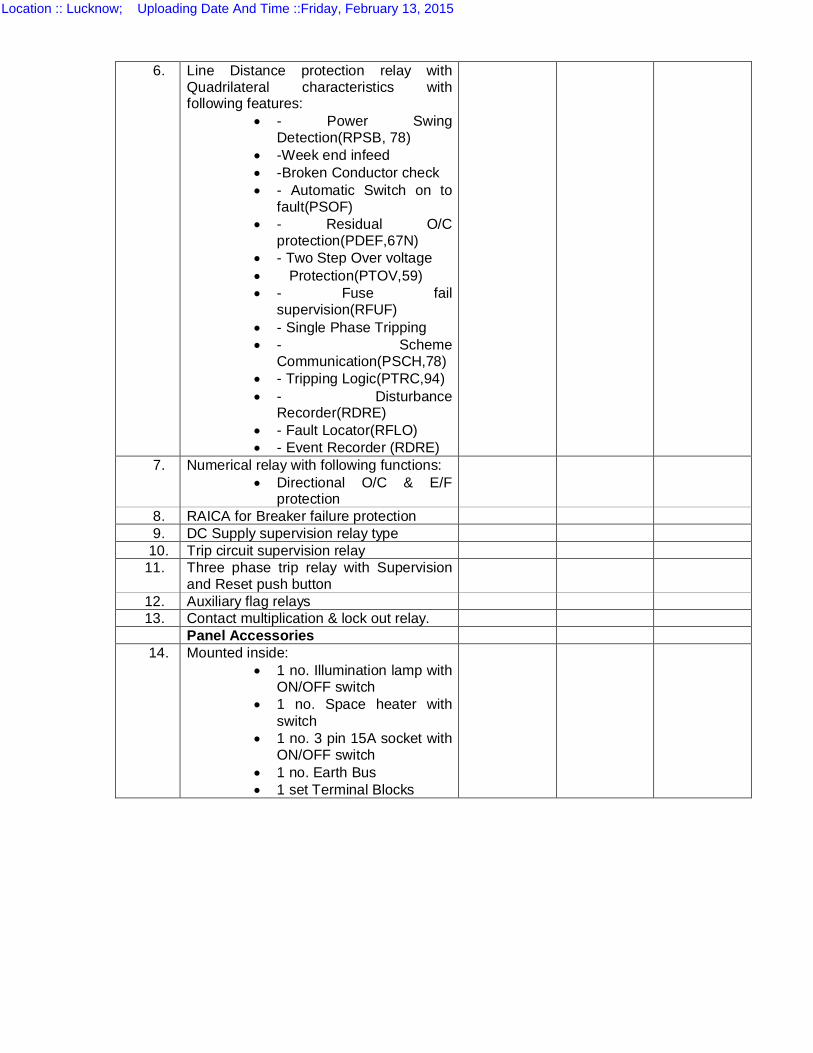
6. Line Distance protection relay with Quadrilateral characteristics with following features:
- Power Swing Detection(RPSB, 78)
-Week end infeed -Broken Conductor check - Automatic Switch on to
fault(PSOF) - Residual O/C
protection(PDEF,67N) - Two Step Over voltage Protection(PTOV,59) - Fuse fail
supervision(RFUF) - Single Phase Tripping - Scheme
Communication(PSCH,78) - Tripping Logic(PTRC,94) - Disturbance
Recorder(RDRE) - Fault Locator(RFLO) - Event Recorder (RDRE)
7. Numerical relay with following functions: Directional O/C & E/F
protection
8. RAICA for Breaker failure protection 9. DC Supply supervision relay type
10. Trip circuit supervision relay 11. Three phase trip relay with Supervision
and Reset push button
12. Auxiliary flag relays 13. Contact multiplication & lock out relay. Panel Accessories 14. Mounted inside:
1 no. Illumination lamp with ON/OFF switch
1 no. Space heater with switch
1 no. 3 pin 15A socket with ON/OFF switch
1 no. Earth Bus 1 set Terminal Blocks
Location :: Lucknow; Uploading Date And Time ::Friday, February 13, 2015
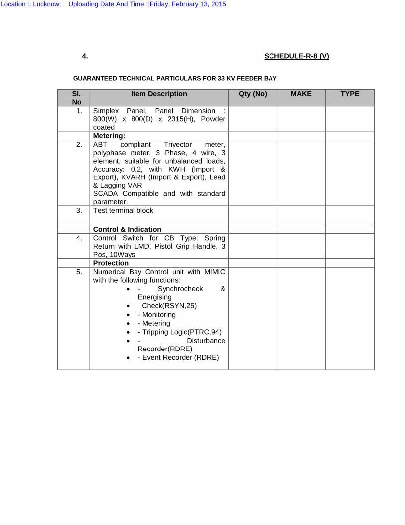
4. SCHEDULE-R-8 (V)
GUARANTEED TECHNICAL PARTICULARS FOR 33 KV FEEDER BAY
Sl. No
Item Description Qty (No) MAKE TYPE
1. Simplex Panel, Panel Dimension : 800(W) x 800(D) x 2315(H), Powder coated
Metering: 2. ABT compliant Trivector meter,
polyphase meter, 3 Phase, 4 wire, 3 element, suitable for unbalanced loads, Accuracy: 0.2, with KWH (Import & Export), KVARH (Import & Export), Lead & Lagging VAR SCADA Compatible and with standard parameter.
3. Test terminal block
Control & Indication 4. Control Switch for CB Type: Spring
Return with LMD, Pistol Grip Handle, 3 Pos, 10Ways
Protection 5. Numerical Bay Control unit with MIMIC
with the following functions: - Synchrocheck &
Energising Check(RSYN,25) - Monitoring - Metering - Tripping Logic(PTRC,94) - Disturbance
Recorder(RDRE) - Event Recorder (RDRE)
Location :: Lucknow; Uploading Date And Time ::Friday, February 13, 2015
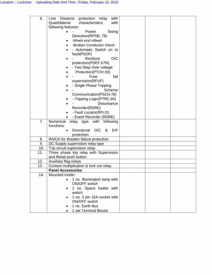
6. Line Distance protection relay with Quadrilateral characteristics with following features:
- Power Swing Detection(RPSB, 78)
-Week end infeed -Broken Conductor check - Automatic Switch on to
fault(PSOF) - Residual O/C
protection(PDEF,67N) - Two Step Over voltage Protection(PTOV,59) - Fuse fail
supervision(RFUF) - Single Phase Tripping - Scheme
Communication(PSCH,78) - Tripping Logic(PTRC,94) - Disturbance
Recorder(RDRE) - Fault Locator(RFLO) - Event Recorder (RDRE)
7. Numerical relay type with following functions:
Directional O/C & E/F protection
8. RAICA for Breaker failure protection 9. DC Supply supervision relay type
10. Trip circuit supervision relay 11. Three phase trip relay with Supervision
and Reset push button
12. Auxiliary flag relays 13. Contact multiplication & lock out relay. Panel Accessories 14. Mounted inside:
1 no. Illumination lamp with ON/OFF switch
1 no. Space heater with switch
1 no. 3 pin 15A socket with ON/OFF switch
1 no. Earth Bus 1 set Terminal Blocks
Location :: Lucknow; Uploading Date And Time ::Friday, February 13, 2015
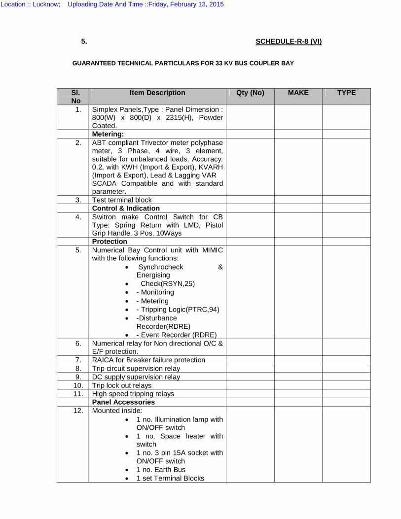
5. SCHEDULE-R-8 (VI)
GUARANTEED TECHNICAL PARTICULARS FOR 33 KV BUS COUPLER BAY
Sl. No
Item Description Qty (No) MAKE TYPE
1. Simplex Panels,Type : Panel Dimension : 800(W) x 800(D) x 2315(H), Powder Coated.
Metering: 2. ABT compliant Trivector meter polyphase
meter, 3 Phase, 4 wire, 3 element, suitable for unbalanced loads, Accuracy: 0.2, with KWH (Import & Export), KVARH (Import & Export), Lead & Lagging VAR SCADA Compatible and with standard parameter.
3. Test terminal block Control & Indication 4. Switron make Control Switch for CB
Type: Spring Return with LMD, Pistol Grip Handle, 3 Pos, 10Ways
Protection 5. Numerical Bay Control unit with MIMIC
with the following functions: Synchrocheck &
Energising Check(RSYN,25) - Monitoring - Metering - Tripping Logic(PTRC,94) -Disturbance
Recorder(RDRE) - Event Recorder (RDRE)
6. Numerical relay for Non directional O/C & E/F protection.
7. RAICA for Breaker failure protection 8. Trip circuit supervision relay 9. DC supply supervision relay
10. Trip lock out relays 11. High speed tripping relays
Panel Accessories 12. Mounted inside:
1 no. Illumination lamp with ON/OFF switch
1 no. Space heater with switch
1 no. 3 pin 15A socket with ON/OFF switch
1 no. Earth Bus 1 set Terminal Blocks
Location :: Lucknow; Uploading Date And Time ::Friday, February 13, 2015
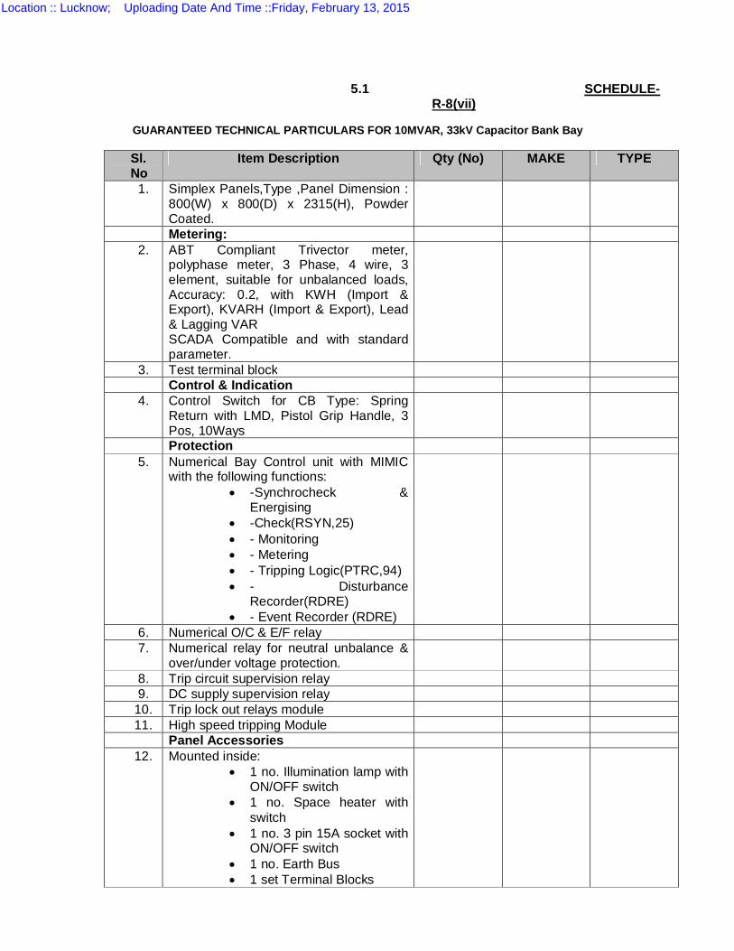
5.1 SCHEDULE-R-8(vii)
GUARANTEED TECHNICAL PARTICULARS FOR 10MVAR, 33kV Capacitor Bank Bay
Sl. No
Item Description Qty (No) MAKE TYPE
1. Simplex Panels,Type ,Panel Dimension : 800(W) x 800(D) x 2315(H), Powder Coated.
Metering: 2. ABT Compliant Trivector meter,
polyphase meter, 3 Phase, 4 wire, 3 element, suitable for unbalanced loads, Accuracy: 0.2, with KWH (Import & Export), KVARH (Import & Export), Lead & Lagging VAR SCADA Compatible and with standard parameter.
3. Test terminal block Control & Indication 4. Control Switch for CB Type: Spring
Return with LMD, Pistol Grip Handle, 3 Pos, 10Ways
Protection 5. Numerical Bay Control unit with MIMIC
with the following functions: -Synchrocheck &
Energising -Check(RSYN,25) - Monitoring - Metering - Tripping Logic(PTRC,94) - Disturbance
Recorder(RDRE) - Event Recorder (RDRE)
6. Numerical O/C & E/F relay 7. Numerical relay for neutral unbalance &
over/under voltage protection.
8. Trip circuit supervision relay 9. DC supply supervision relay
10. Trip lock out relays module 11. High speed tripping Module
Panel Accessories 12. Mounted inside:
1 no. Illumination lamp with ON/OFF switch
1 no. Space heater with switch
1 no. 3 pin 15A socket with ON/OFF switch
1 no. Earth Bus 1 set Terminal Blocks
Location :: Lucknow; Uploading Date And Time ::Friday, February 13, 2015
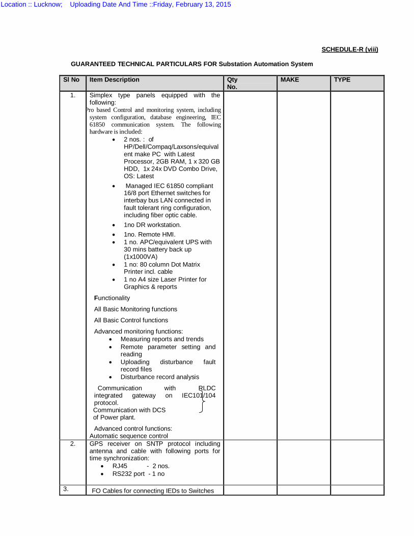
SCHEDULE-R (viii)
GUARANTEED TECHNICAL PARTICULARS FOR Substation Automation System
Sl No Item Description Qty No.
MAKE TYPE
1. Simplex type panels equipped with the following:
icro SCADA Pro based Control and monitoring system, including system configuration, database engineering, IEC 61850 communication system. The following hardware is included:
2 nos. : of HP/Dell/Compaq/Laxsons/equivalent make PC with Latest Processor, 2GB RAM, 1 x 320 GB HDD, 1x 24x DVD Combo Drive, OS: Latest
Managed IEC 61850 compliant 16/8 port Ethernet switches for interbay bus LAN connected in fault tolerant ring configuration, including fiber optic cable.
1no DR workstation. 1no. Remote HMI. 1 no. APC/equivalent UPS with
30 mins battery back up (1x1000VA)
1 no: 80 column Dot Matrix Printer incl. cable
1 no A4 size Laser Printer for Graphics & reports
Functionality
All Basic Monitoring functions
All Basic Control functions
Advanced monitoring functions: Measuring reports and trends Remote parameter setting and
reading Uploading disturbance fault
record files Disturbance record analysis
Communication with RLDC integrated gateway on IEC101/104 protocol.
Communication with DCS of Power plant.
Advanced control functions: Automatic sequence control
2. GPS receiver on SNTP protocol including antenna and cable with following ports for time synchronization:
RJ45 - 2 nos. RS232 port - 1 no
3. FO Cables for connecting IEDs to Switches
Location :: Lucknow; Uploading Date And Time ::Friday, February 13, 2015
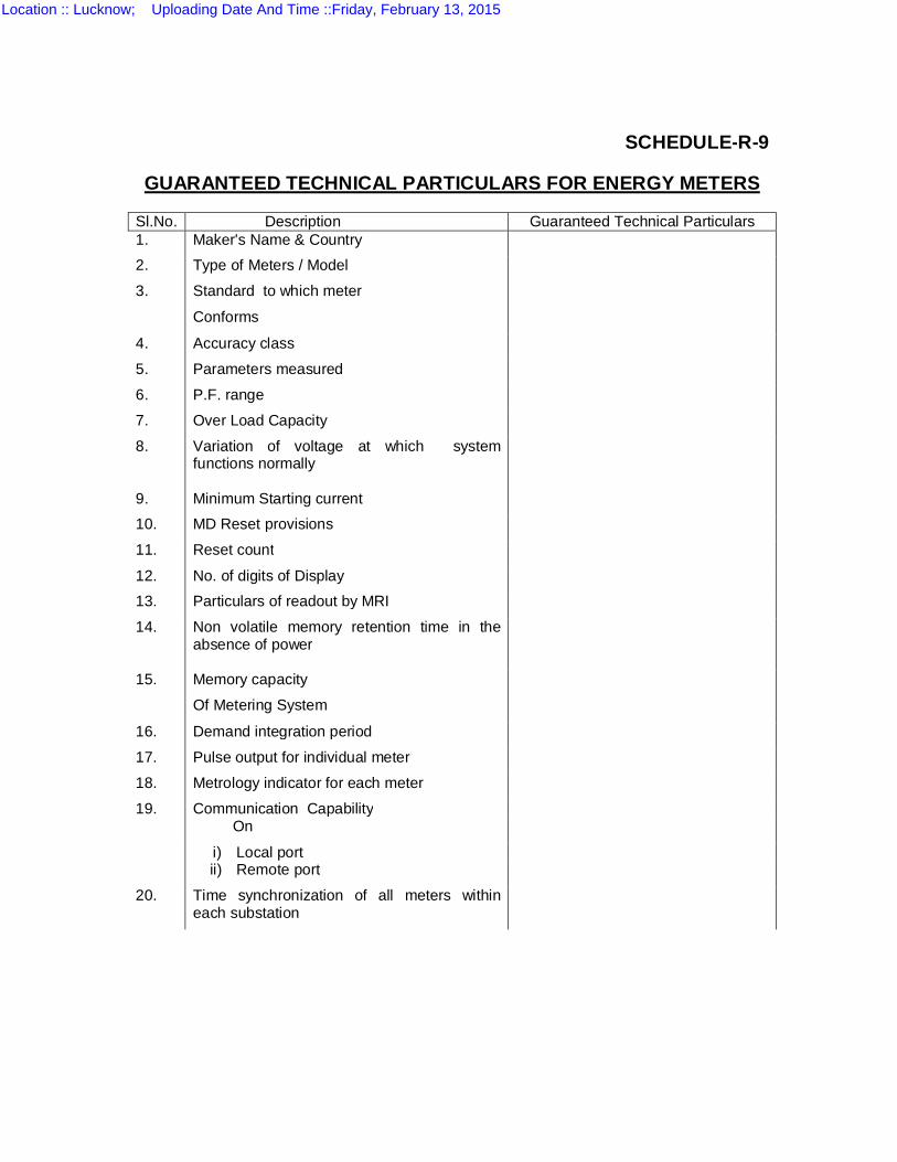
SCHEDULE-R-9 GUARANTEED TECHNICAL PARTICULARS FOR ENERGY METERS
Sl.No. Description Guaranteed Technical Particulars 1. Maker's Name & Country 2. Type of Meters / Model 3.
Standard to which meter Conforms
4. Accuracy class 5. Parameters measured 6. P.F. range 7. Over Load Capacity 8.
Variation of voltage at which system functions normally
9. Minimum Starting current 10. MD Reset provisions 11. Reset count 12. No. of digits of Display 13. Particulars of readout by MRI 14.
Non volatile memory retention time in the absence of power
15.
Memory capacity Of Metering System
16. Demand integration period 17. Pulse output for individual meter 18. Metrology indicator for each meter 19.
Communication Capability On
i) Local port ii) Remote port
20. Time synchronization of all meters within each substation
Location :: Lucknow; Uploading Date And Time ::Friday, February 13, 2015
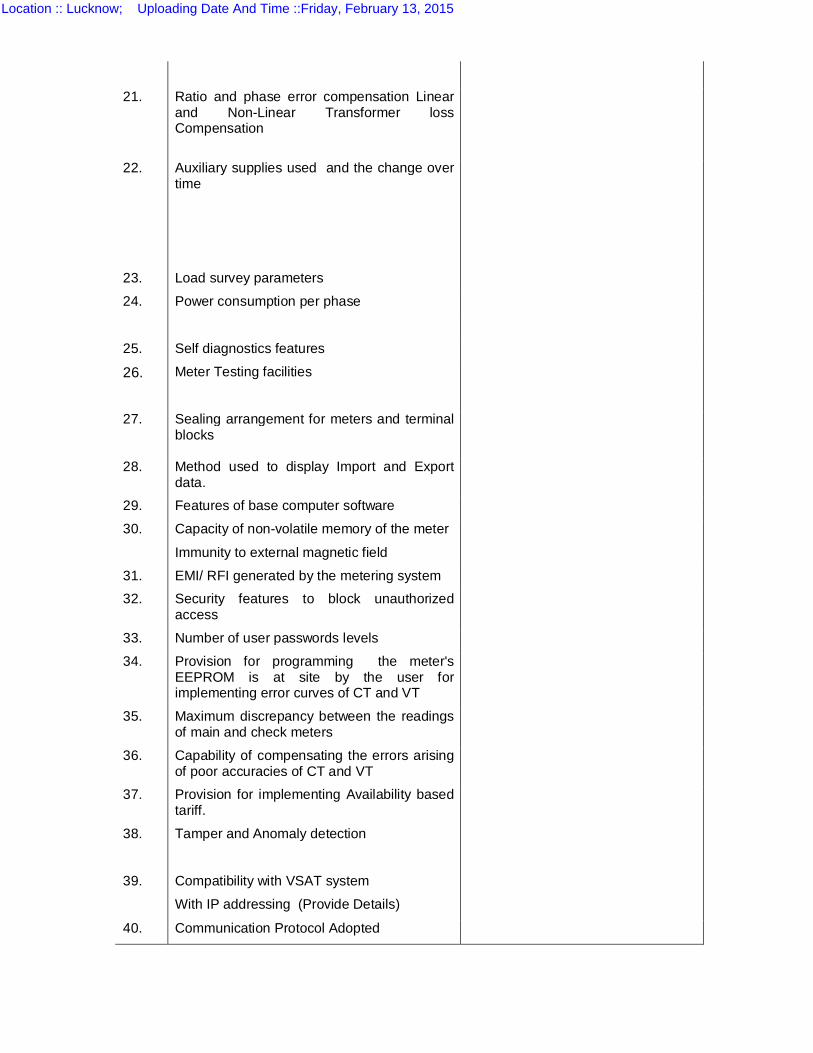
21.
Ratio and phase error compensation Linear and Non-Linear Transformer loss Compensation
22. Auxiliary supplies used and the change over time
23. Load survey parameters 24. Power consumption per phase 25. Self diagnostics features 26. Meter Testing facilities
27.
Sealing arrangement for meters and terminal blocks
28. Method used to display Import and Export data.
29. Features of base computer software 30. Capacity of non-volatile memory of the meter
Immunity to external magnetic field
31. EMI/ RFI generated by the metering system 32. Security features to block unauthorized
access
33. Number of user passwords levels 34. Provision for programming the meter's
EEPROM is at site by the user for implementing error curves of CT and VT
35. Maximum discrepancy between the readings of main and check meters
36. Capability of compensating the errors arising of poor accuracies of CT and VT
37. Provision for implementing Availability based tariff.
38.
Tamper and Anomaly detection
39.
Compatibility with VSAT system With IP addressing (Provide Details)
40. Communication Protocol Adopted
Location :: Lucknow; Uploading Date And Time ::Friday, February 13, 2015
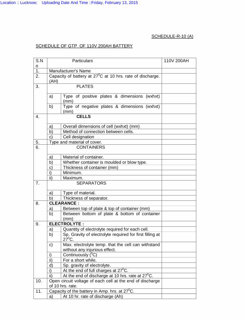
SCHEDULE-R-10 (A)
SCHEDULE OF GTP OF 110V 200AH BATTERY
S.No
Particulars 110V 200AH
1. Manufacturer's Name 2. Capacity of battery at 270C at 10 hrs. rate of discharge.
(AH)
3. PLATES
a) Type of positive plates & dimensions (wxhxt) (mm)
b) Type of negative plates & dimensions (wxhxt) (mm)
4. CELLS
a) Overall dimensions of cell (wxhxt) (mm) b) Method of connection between cells. c) Cell designation
5. Type and material of cover. 6. CONTAINERS
a) Material of container. b) Whether container is moulded or blow type. c) Thickness of container (mm) i) Minimum. ii) Maximum.
7. SEPARATORS
a) Type of material. b) Thickness of separator.
8. CLEARANCE : a) Between top of plate & top of container (mm) b) Between bottom of plate & bottom of container
(mm)
9. ELECTROLYTE : a) Quantity of electrolyte required for each cell. b) Sp. Gravity of electrolyte required for first filling at
270C.
c) Max. electrolyte temp. that the cell can withstand without any injurious effect.
i) Continuously (0C) ii) For a short while. d) Sp. gravity of electrolyte. i) At the end of full charges at 270C. ii) At the end of discharge at 10 hrs. rate at 270C.
10. Open circuit voltage of each cell at the end of discharge of 10 hrs. rate.
11. Capacity of the battery in Amp. hrs. at 270C. a) At 10 hr. rate of discharge (Ah)
Location :: Lucknow; Uploading Date And Time ::Friday, February 13, 2015
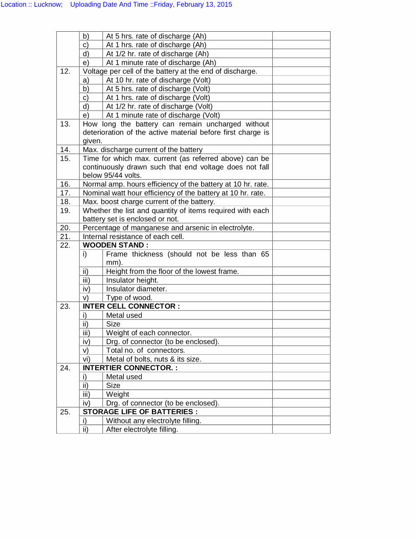
b) At 5 hrs. rate of discharge (Ah) c) At 1 hrs. rate of discharge (Ah) d) At 1/2 hr. rate of discharge (Ah) e) At 1 minute rate of discharge (Ah)
12. Voltage per cell of the battery at the end of discharge. a) At 10 hr. rate of discharge (Volt) b) At 5 hrs. rate of discharge (Volt) c) At 1 hrs. rate of discharge (Volt) d) At 1/2 hr. rate of discharge (Volt) e) At 1 minute rate of discharge (Volt)
13. How long the battery can remain uncharged without deterioration of the active material before first charge is given.
14. Max. discharge current of the battery 15. Time for which max. current (as referred above) can be
continuously drawn such that end voltage does not fall below 95/44 volts.
16. Normal amp. hours efficiency of the battery at 10 hr. rate. 17. Nominal watt hour efficiency of the battery at 10 hr. rate. 18. Max. boost charge current of the battery. 19. Whether the list and quantity of items required with each
battery set is enclosed or not.
20. Percentage of manganese and arsenic in electrolyte. 21. Internal resistance of each cell. 22. WOODEN STAND :
i) Frame thickness (should not be less than 65 mm).
ii) Height from the floor of the lowest frame. iii) Insulator height. iv) Insulator diameter. v) Type of wood.
23. INTER CELL CONNECTOR : i) Metal used ii) Size iii) Weight of each connector. iv) Drg. of connector (to be enclosed). v) Total no. of connectors. vi) Metal of bolts, nuts & its size.
24. INTERTIER CONNECTOR. : i) Metal used ii) Size iii) Weight iv) Drg. of connector (to be enclosed).
25. STORAGE LIFE OF BATTERIES : i) Without any electrolyte filling. ii) After electrolyte filling.
Location :: Lucknow; Uploading Date And Time ::Friday, February 13, 2015
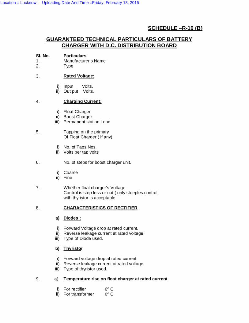
SCHEDULE –R-10 (B)
GUARANTEED TECHNICAL PARTICULARS OF BATTERY
CHARGER WITH D.C. DISTRIBUTION BOARD
SI. No. Particulars 1. Manufacturer’s Name 2. Type 3. Rated Voltage:
i) Input Volts. ii) Out put Volts.
4. Charging Current:
i) Float Charger ii) Boost Charger iii) Permanent station Load
5. Tapping on the primary Of Float Charger ( if any)
i) No, of Taps Nos. ii) Volts per tap volts
6. No. of steps for boost charger unit.
i) Coarse ii) Fine
7. Whether float charger’s Voltage Control is step less or not ( only steeples control with thyristor is acceptable 8. CHARACTERISTICS OF RECTIFIER
a) Diodes :
i) Forward Voltage drop at rated current. ii) Reverse leakage current at rated voltage iii) Type of Diode used.
b) Thyristor
i) Forward voltage drop at rated current. ii) Reverse leakage current at rated voltage iii) Type of thyristor used.
9. a) Temperature rise on float charger at rated current
i) For rectifier 0º C ii) For transformer 0º C
Location :: Lucknow; Uploading Date And Time ::Friday, February 13, 2015
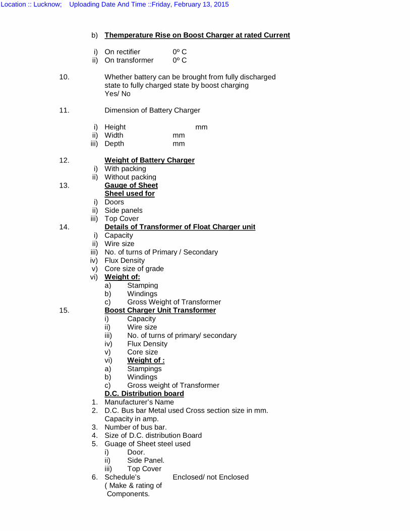
b) Themperature Rise on Boost Charger at rated Current
i) On rectifier 0º C ii) On transformer 0º C
10. Whether battery can be brought from fully discharged state to fully charged state by boost charging Yes/ No 11. Dimension of Battery Charger
i) Height mm ii) Width mm iii) Depth mm
12. Weight of Battery Charger
i) With packing ii) Without packing
13. Gauge of Sheet Sheel used for
i) Doors ii) Side panels iii) Top Cover
14. Details of Transformer of Float Charger unit i) Capacity ii) Wire size iii) No. of turns of Primary / Secondary iv) Flux Density v) Core size of grade vi) Weight of:
a) Stamping b) Windings c) Gross Weight of Transformer 15. Boost Charger Unit Transformer i) Capacity ii) Wire size iii) No. of turns of primary/ secondary iv) Flux Density v) Core size
vi) Weight of : a) Stampings b) Windings c) Gross weight of Transformer D.C. Distribution board
1. Manufacturer’s Name 2. D.C. Bus bar Metal used Cross section size in mm.
Capacity in amp. 3. Number of bus bar. 4. Size of D.C. distribution Board 5. Guage of Sheet steel used
i) Door. ii) Side Panel. iii) Top Cover
6. Schedule’s Enclosed/ not Enclosed ( Make & rating of
Components.
Location :: Lucknow; Uploading Date And Time ::Friday, February 13, 2015
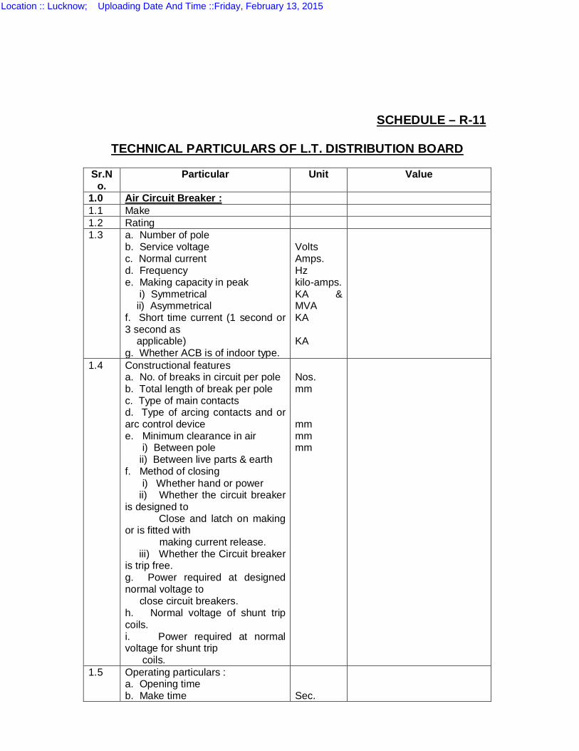
SCHEDULE – R-11
TECHNICAL PARTICULARS OF L.T. DISTRIBUTION BOARD
Sr.No.
Particular Unit Value
1.0 Air Circuit Breaker : 1.1 Make 1.2 Rating 1.3 a. Number of pole
b. Service voltage c. Normal current d. Frequency e. Making capacity in peak i) Symmetrical ii) Asymmetrical f. Short time current (1 second or 3 second as applicable) g. Whether ACB is of indoor type.
Volts Amps. Hz kilo-amps. KA & MVA KA KA
1.4 Constructional features a. No. of breaks in circuit per pole b. Total length of break per pole c. Type of main contacts d. Type of arcing contacts and or arc control device e. Minimum clearance in air i) Between pole ii) Between live parts & earth f. Method of closing i) Whether hand or power ii) Whether the circuit breaker is designed to Close and latch on making or is fitted with making current release. iii) Whether the Circuit breaker is trip free. g. Power required at designed normal voltage to close circuit breakers. h. Normal voltage of shunt trip coils. i. Power required at normal voltage for shunt trip coils.
Nos. mm mm mm mm
1.5 Operating particulars : a. Opening time b. Make time
Sec.
Location :: Lucknow; Uploading Date And Time ::Friday, February 13, 2015
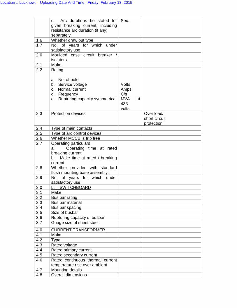
c. Arc durations be stated for given breaking current, including resistance arc duration (if any) separately.
Sec.
1.6 Whether draw out type 1.7 No. of years for which under
satisfactory use.
2.0 Moulded case circuit breaker / isolators
2.1 Make 2.2 Rating
a. No. of pole b. Service voltage c. Normal current d. Frequency e. Rupturing capacity symmetrical
Volts Amps. C/s MVA at 433 volts.
2.3 Protection devices Over load/ short circuit protection.
2.4 Type of main contacts 2.5 Type of arc control devices 2.6 Whether MCCB is trip free 2.7 Operating particulars
a. Operating time at rated breaking current b. Make time at rated / breaking current
2.8 Whether provided with standard flush mounting base assembly.
2.9 No. of years for which under satisfactory use.
3.0 L.T. SWITCHBOARD 3.1 Make 3.2 Bus bar rating 3.3 Bus bar material 3.4 Bus bar spacing 3.5 Size of busbar 3.6 Rupturing capacity of busbar 3.7 Guage size of sheet steel.
4.0 CURRENT TRANSFORMER 4.1 Make 4.2 Type 4.3 Rated voltage 4.4 Rated primary current 4.5 Rated secondary current 4.6 Rated continuous thermal current
temperature rise over ambient
4.7 Mounting details 4.8 Overall dimensions
Location :: Lucknow; Uploading Date And Time ::Friday, February 13, 2015
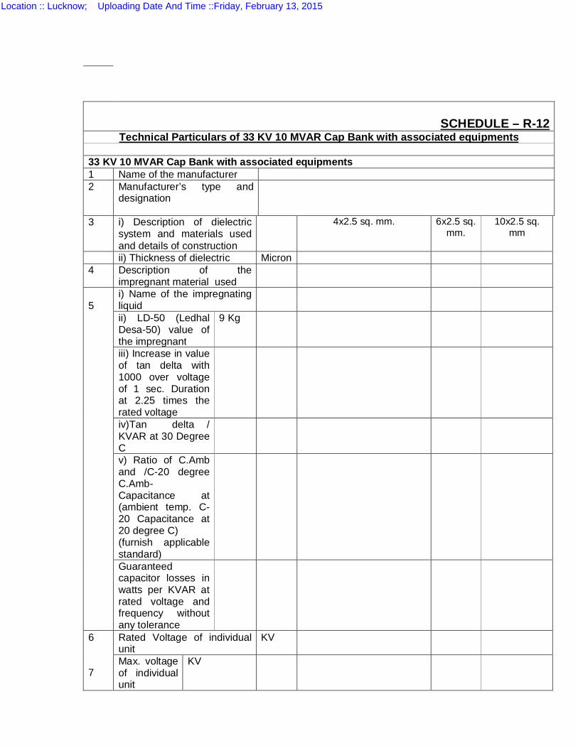
SCHEDULE – R-12 Technical Particulars of 33 KV 10 MVAR Cap Bank with associated equipments
33 KV 10 MVAR Cap Bank with associated equipments 1 Name of the manufacturer 2
Manufacturer’s type and designation
3 i) Description of dielectric system and materials used and details of construction
4x2.5 sq. mm. 6x2.5 sq. mm.
10x2.5 sq. mm
ii) Thickness of dielectric Micron 4 Description of the
impregnant material used
5
i) Name of the impregnating liquid
ii) LD-50 (Ledhal Desa-50) value of the impregnant
9 Kg
iii) Increase in value of tan delta with 1000 over voltage of 1 sec. Duration at 2.25 times the rated voltage
iv)Tan delta / KVAR at 30 Degree C
v) Ratio of C.Amb and /C-20 degree C.Amb-Capacitance at (ambient temp. C-20 Capacitance at 20 degree C) (furnish applicable standard)
Guaranteed capacitor losses in watts per KVAR at rated voltage and frequency without any tolerance
6 7
Rated Voltage of individual unit
KV
Max. voltage of individual unit
KV
Location :: Lucknow; Uploading Date And Time ::Friday, February 13, 2015
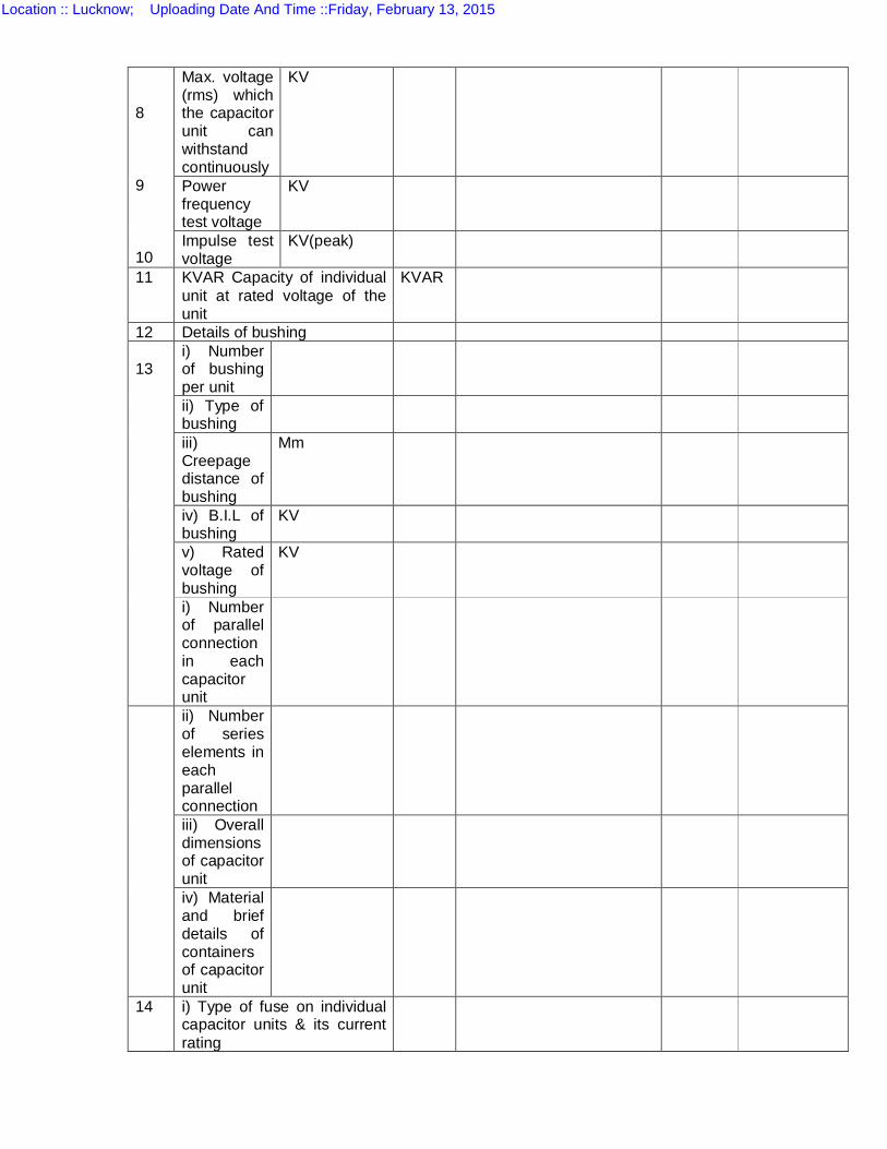
8 9 10
Max. voltage (rms) which the capacitor unit can withstand continuously
KV
Power frequency test voltage
KV
Impulse test voltage
KV(peak)
11 KVAR Capacity of individual unit at rated voltage of the unit
KVAR
12 Details of bushing 13
i) Number of bushing per unit
ii) Type of bushing
iii) Creepage distance of bushing
Mm
iv) B.I.L of bushing
KV
v) Rated voltage of bushing
KV
i) Number of parallel connection in each capacitor unit
ii) Number of series elements in each parallel connection
iii) Overall dimensions of capacitor unit
iv) Material and brief details of containers of capacitor unit
14 i) Type of fuse on individual capacitor units & its current rating
Location :: Lucknow; Uploading Date And Time ::Friday, February 13, 2015
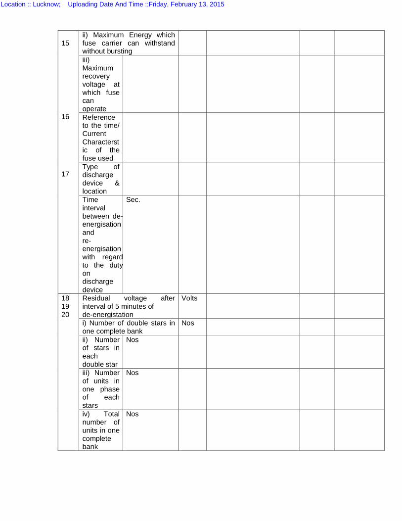
15 16 17
ii) Maximum Energy which fuse carrier can withstand without bursting
iii) Maximum recovery voltage at which fuse can operate
Reference to the time/ Current Characterstic of the fuse used
Type of discharge device & location
Time interval between de-energisation and re-energisation with regard to the duty on discharge device
Sec.
18 19 20
Residual voltage after interval of 5 minutes of de-energistation
Volts
i) Number of double stars in one complete bank
Nos
ii) Number of stars in each double star
Nos
iii) Number of units in one phase of each stars
Nos
iv) Total number of units in one complete bank
Nos
Location :: Lucknow; Uploading Date And Time ::Friday, February 13, 2015

i) Rated output of each bank a) at 38KV b) at 33KV
MVAR MVAR
ii) Output of each double star a) at 38KV b) at 33KV
MVAR MVAR
iii) Output of each star at a) at 38KV b) at 33KV
MVAR MVAR
21 Height of complete bank including support insulators
Mm
22 i) Weight of each capacitor unit
ii) Weight of mounting racks without insulators
iii) Total weight of one complete bank including units, interconnectors, connectors, mounting rack and insulators
23 Mounting arrangement
i) Reference of GA drawing furnished
ii) Number of tier arrangement
iii) Mounting steel rack galvnised or painted
iv) Without elevating structures, suitable for mounting on plinth or not
Yes/No
24 Provision of sun-shade during hot part of the year is required or not
Yes/No
25. Reference to standard in respect of cables.
Location :: Lucknow; Uploading Date And Time ::Friday, February 13, 2015
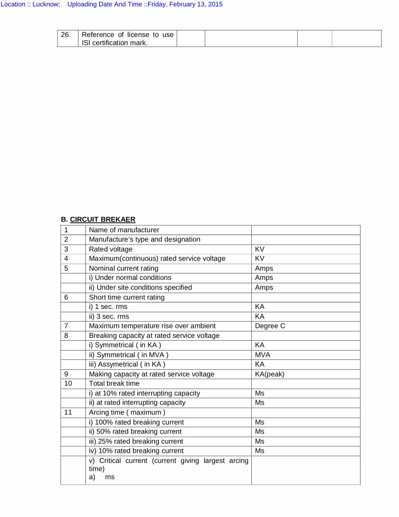
B. CIRCUIT BREKAER
26. Reference of license to use ISI certification mark.
1 Name of manufacturer 2 Manufacture’s type and designation 3 Rated voltage KV 4 Maximum(continuous) rated service voltage KV 5 Nominal current rating Amps i) Under normal conditions Amps ii) Under site conditions specified Amps 6 Short time current rating i) 1 sec. rms KA ii) 3 sec. rms KA 7 Maximum temperature rise over ambient Degree C 8 Breaking capacity at rated service voltage i) Symmetrical ( in KA ) KA ii) Symmetrical ( in MVA ) MVA iii) Assymetrical ( in KA ) KA 9 Making capacity at rated service voltage KA(peak) 10 Total break time i) at 10% rated interrupting capacity Ms ii) at rated interrupting capacity Ms 11 Arcing time ( maximum ) i) 100% rated breaking current Ms ii) 50% rated breaking current Ms iii) 25% rated breaking current Ms iv) 10% rated breaking current Ms v) Critical current (current giving largest arcing
time) a) ms
Location :: Lucknow; Uploading Date And Time ::Friday, February 13, 2015
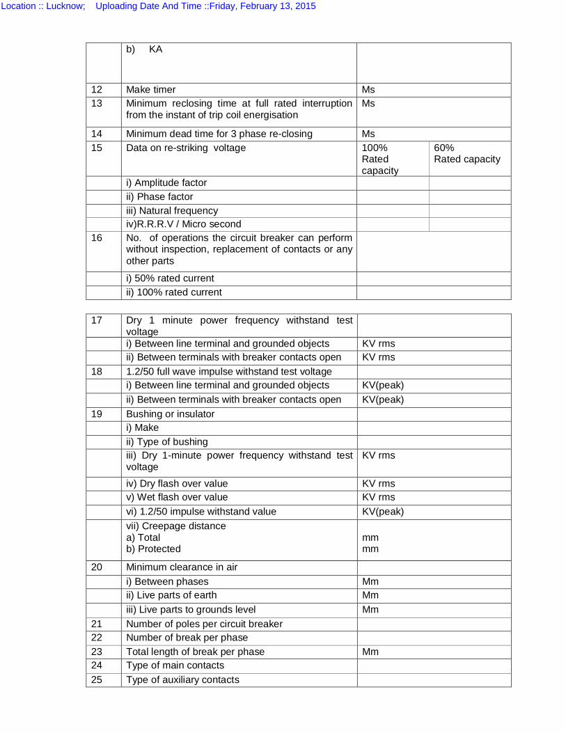
b) KA
12 Make timer Ms 13 Minimum reclosing time at full rated interruption
from the instant of trip coil energisation Ms
14 Minimum dead time for 3 phase re-closing Ms 15 Data on re-striking voltage 100%
Rated capacity
60% Rated capacity
i) Amplitude factor ii) Phase factor iii) Natural frequency iv)R.R.R.V / Micro second 16 No. of operations the circuit breaker can perform
without inspection, replacement of contacts or any other parts
i) 50% rated current ii) 100% rated current
17 Dry 1 minute power frequency withstand test voltage
i) Between line terminal and grounded objects KV rms ii) Between terminals with breaker contacts open KV rms 18 1.2/50 full wave impulse withstand test voltage i) Between line terminal and grounded objects KV(peak) ii) Between terminals with breaker contacts open KV(peak) 19 Bushing or insulator i) Make ii) Type of bushing iii) Dry 1-minute power frequency withstand test
voltage KV rms
iv) Dry flash over value KV rms v) Wet flash over value KV rms vi) 1.2/50 impulse withstand value KV(peak) vii) Creepage distance
a) Total b) Protected
mm mm
20 Minimum clearance in air i) Between phases Mm ii) Live parts of earth Mm iii) Live parts to grounds level Mm 21 Number of poles per circuit breaker 22 Number of break per phase 23 Total length of break per phase Mm 24 Type of main contacts 25 Type of auxiliary contacts
Location :: Lucknow; Uploading Date And Time ::Friday, February 13, 2015
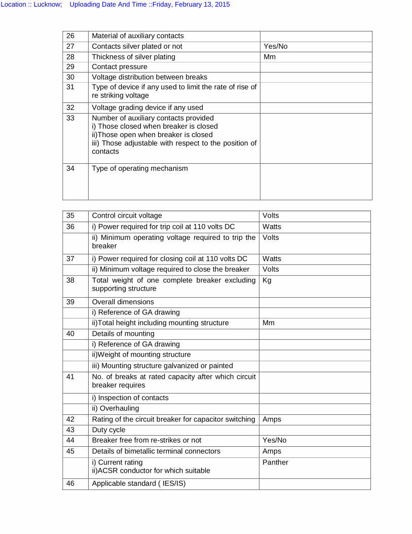
26 Material of auxiliary contacts 27 Contacts silver plated or not Yes/No 28 Thickness of silver plating Mm 29 Contact pressure 30 Voltage distribution between breaks 31 Type of device if any used to limit the rate of rise of
re striking voltage
32 Voltage grading device if any used 33 Number of auxiliary contacts provided
i) Those closed when breaker is closed ii)Those open when breaker is closed iii) Those adjustable with respect to the position of contacts
34 Type of operating mechanism
35 Control circuit voltage Volts 36 i) Power required for trip coil at 110 volts DC Watts ii) Minimum operating voltage required to trip the
breaker Volts
37 i) Power required for closing coil at 110 volts DC Watts ii) Minimum voltage required to close the breaker Volts 38 Total weight of one complete breaker excluding
supporting structure Kg
39 Overall dimensions i) Reference of GA drawing ii)Total height including mounting structure Mm 40 Details of mounting i) Reference of GA drawing ii)Weight of mounting structure iii) Mounting structure galvanized or painted 41 No. of breaks at rated capacity after which circuit
breaker requires
i) Inspection of contacts ii) Overhauling 42 Rating of the circuit breaker for capacitor switching Amps 43 Duty cycle 44 Breaker free from re-strikes or not Yes/No 45 Details of bimetallic terminal connectors Amps i) Current rating
ii)ACSR conductor for which suitable Panther
46 Applicable standard ( IES/IS)
Location :: Lucknow; Uploading Date And Time ::Friday, February 13, 2015
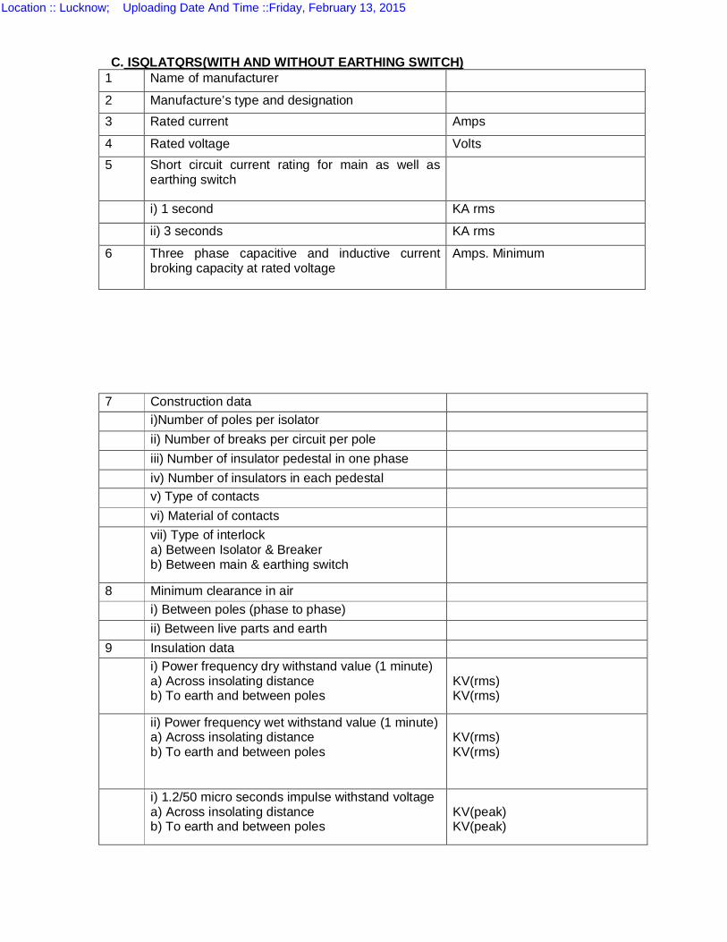
C. ISQLATQRS(WITH AND WITHOUT EARTHING SWITCH) 1 Name of manufacturer
2 Manufacture’s type and designation 3 Rated current Amps
4 Rated voltage Volts 5 Short circuit current rating for main as well as
earthing switch
i) 1 second KA rms
ii) 3 seconds KA rms
6 Three phase capacitive and inductive current broking capacity at rated voltage
Amps. Minimum
7 Construction data i)Number of poles per isolator ii) Number of breaks per circuit per pole iii) Number of insulator pedestal in one phase iv) Number of insulators in each pedestal v) Type of contacts vi) Material of contacts vii) Type of interlock
a) Between Isolator & Breaker b) Between main & earthing switch
8 Minimum clearance in air i) Between poles (phase to phase) ii) Between live parts and earth 9 Insulation data i) Power frequency dry withstand value (1 minute)
a) Across insolating distance b) To earth and between poles
KV(rms) KV(rms)
ii) Power frequency wet withstand value (1 minute) a) Across insolating distance b) To earth and between poles
KV(rms) KV(rms)
i) 1.2/50 micro seconds impulse withstand voltage a) Across insolating distance b) To earth and between poles
KV(peak) KV(peak)
Location :: Lucknow; Uploading Date And Time ::Friday, February 13, 2015

10 Maximum temperature rise of current carrying parts when carrying rated current continuously over ambient temperature of 50 degree C
11 Insulator used for Isolators i) Make of Insulators ii) Total creepage distance 12 Number of operations the isolators can withstand
without deterioration of contacts
13 Weight with insulators i) With earthing switch Kg ii) without earthing switch Kg 14 Dimensions i) Reference of GA drawing ii) Total height 15 Mounting details i) Reference of GA drawing ii) Total height
b) Over voltage protection i) Type and make of relays offered ii) Setting range in voltage and time available
Location :: Lucknow; Uploading Date And Time ::Friday, February 13, 2015
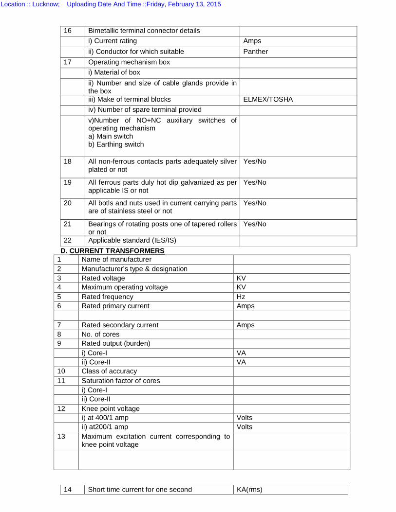
D. CURRENT TRANSFORMERS 1 Name of manufacturer 2 Manufacturer’s type & designation 3 Rated voltage KV 4 Maximum operating voltage KV 5 Rated frequency Hz 6 Rated primary current Amps 7 Rated secondary current Amps 8 No. of cores 9 Rated output (burden) i) Core-I VA ii) Core-II VA 10 Class of accuracy 11 Saturation factor of cores i) Core-I ii) Core-II 12 Knee point voltage i) at 400/1 amp Volts ii) at200/1 amp Volts 13 Maximum excitation current corresponding to
knee point voltage
16 Bimetallic terminal connector details i) Current rating Amps ii) Conductor for which suitable Panther 17 Operating mechanism box i) Material of box ii) Number and size of cable glands provide in
the box
iii) Make of terminal blocks ELMEX/TOSHA iv) Number of spare terminal provied v)Number of NO+NC auxiliary switches of
operating mechanism a) Main switch b) Earthing switch
18 All non-ferrous contacts parts adequately silver plated or not
Yes/No
19 All ferrous parts duly hot dip galvanized as per applicable IS or not
Yes/No
20 All botls and nuts used in current carrying parts are of stainless steel or not
Yes/No
21 Bearings of rotating posts one of tapered rollers or not
Yes/No
22 Applicable standard (IES/IS)
14 Short time current for one second KA(rms)
Location :: Lucknow; Uploading Date And Time ::Friday, February 13, 2015
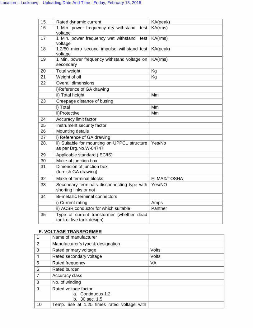
E. VOLTAGE TRANSFORMER
1 Name of manufacturer 2 Manufacturer’s type & designation 3 Rated primary voltage Volts 4 Rated secondary voltage Volts 5 Rated frequency VA 6 Rated burden 7 Accuracy class 8 No. of winding 9. Rated voltage factor
a. Continuous 1.2 b. 30 sec. 1.5
10 Temp. rise at 1.25 times rated voltage with
15 Rated dynamic current KA(peak) 16 1 Min. power frequency dry withstand test
voltage KA(rms)
17 1 Min. power frequency wet withstand test voltage
KA(rms)
18 1.2/50 micro second impulse withstand test voltage
KA(peak)
19 1 Min. power frequency withstand voltage on secondary
KA(rms)
20 Total weight Kg 21 Weight of oil Kg 22 Overall dimensions i)Reference of GA drawing ii) Total height Mm 23 Creepage distance of busing i) Total Mm ii)Protective Mm 24 Accuracy limit factor 25 Instrument security factor 26 Mounting details 27 i) Reference of GA drawing 28. ii) Suitable for mounting on UPPCL structure
as per Drg.No.W-04747 Yes/No
29 Applicable standard (IEC/IS) 30 Make of junction box 31 Dimension of junction box
(furnish GA drawing)
32 Make of terminal blocks ELMAX/TOSHA 33 Secondary terminals disconnecting type with
shorting links or not Yes/NO
34 Bi-metallic terminal connectors i) Current rating Amps ii) ACSR conductor for which suitable Panther 35 Type of current transformer (whether dead
tank or live tank design)
Location :: Lucknow; Uploading Date And Time ::Friday, February 13, 2015
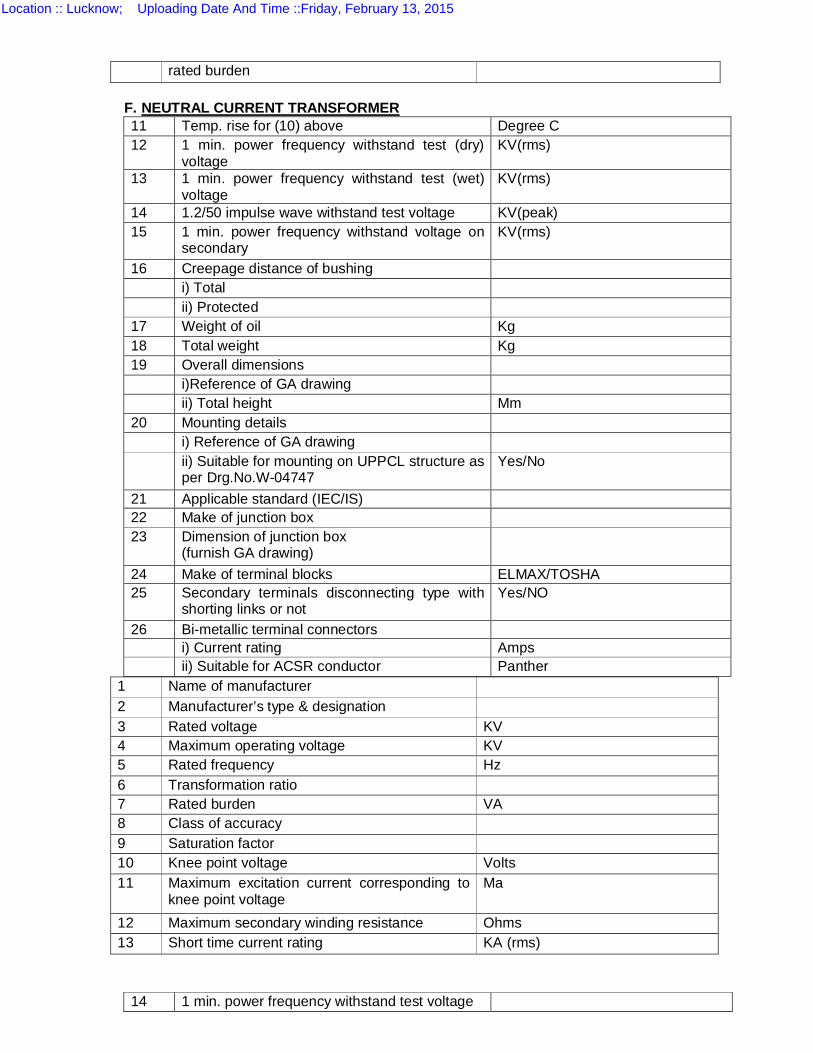
rated burden F. NEUTRAL CURRENT TRANSFORMER
1 Name of manufacturer 2 Manufacturer’s type & designation 3 Rated voltage KV 4 Maximum operating voltage KV 5 Rated frequency Hz 6 Transformation ratio 7 Rated burden VA 8 Class of accuracy 9 Saturation factor 10 Knee point voltage Volts 11 Maximum excitation current corresponding to
knee point voltage Ma
12 Maximum secondary winding resistance Ohms 13 Short time current rating KA (rms)
11 Temp. rise for (10) above Degree C 12 1 min. power frequency withstand test (dry)
voltage KV(rms)
13 1 min. power frequency withstand test (wet) voltage
KV(rms)
14 1.2/50 impulse wave withstand test voltage KV(peak) 15 1 min. power frequency withstand voltage on
secondary KV(rms)
16 Creepage distance of bushing i) Total ii) Protected 17 Weight of oil Kg 18 Total weight Kg 19 Overall dimensions i)Reference of GA drawing ii) Total height Mm 20 Mounting details i) Reference of GA drawing ii) Suitable for mounting on UPPCL structure as
per Drg.No.W-04747 Yes/No
21 Applicable standard (IEC/IS) 22 Make of junction box 23 Dimension of junction box
(furnish GA drawing)
24 Make of terminal blocks ELMAX/TOSHA 25 Secondary terminals disconnecting type with
shorting links or not Yes/NO
26 Bi-metallic terminal connectors i) Current rating Amps ii) Suitable for ACSR conductor Panther
14 1 min. power frequency withstand test voltage
Location :: Lucknow; Uploading Date And Time ::Friday, February 13, 2015
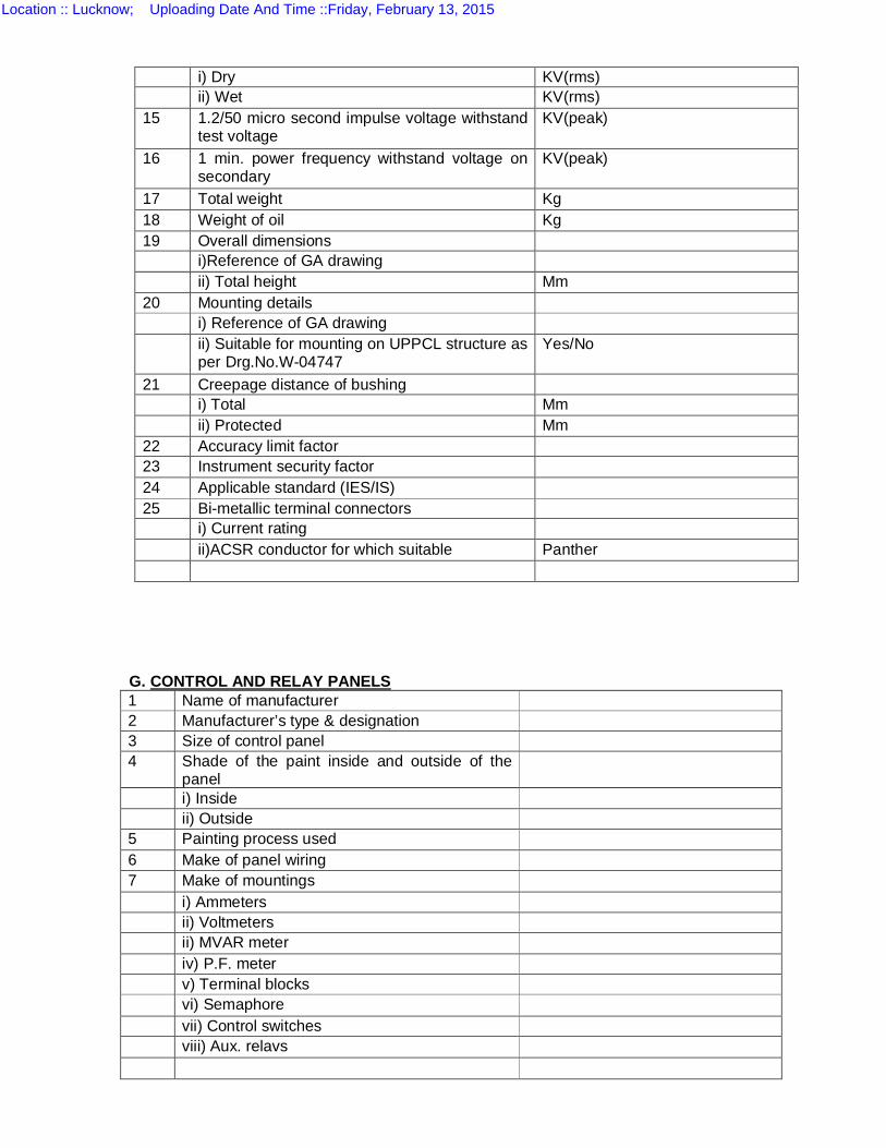
G. CONTROL AND RELAY PANELS 1 Name of manufacturer 2 Manufacturer’s type & designation 3 Size of control panel 4 Shade of the paint inside and outside of the
panel
i) Inside ii) Outside 5 Painting process used 6 Make of panel wiring 7 Make of mountings i) Ammeters ii) Voltmeters ii) MVAR meter iv) P.F. meter v) Terminal blocks vi) Semaphore vii) Control switches viii) Aux. relavs
i) Dry KV(rms) ii) Wet KV(rms) 15 1.2/50 micro second impulse voltage withstand
test voltage KV(peak)
16 1 min. power frequency withstand voltage on secondary
KV(peak)
17 Total weight Kg 18 Weight of oil Kg 19 Overall dimensions i)Reference of GA drawing ii) Total height Mm 20 Mounting details i) Reference of GA drawing ii) Suitable for mounting on UPPCL structure as
per Drg.No.W-04747 Yes/No
21 Creepage distance of bushing i) Total Mm ii) Protected Mm 22 Accuracy limit factor 23 Instrument security factor 24 Applicable standard (IES/IS) 25 Bi-metallic terminal connectors i) Current rating ii)ACSR conductor for which suitable Panther
Location :: Lucknow; Uploading Date And Time ::Friday, February 13, 2015
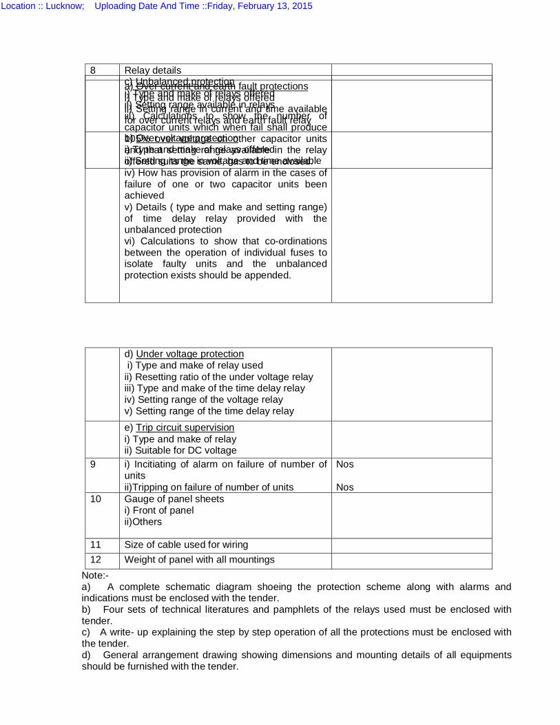
Note:- a) A complete schematic diagram shoeing the protection scheme along with alarms and indications must be enclosed with the tender. b) Four sets of technical literatures and pamphlets of the relays used must be enclosed with tender. c) A write- up explaining the step by step operation of all the protections must be enclosed with the tender. d) General arrangement drawing showing dimensions and mounting details of all equipments should be furnished with the tender.
8 Relay details a) Over current and earth fault protections
i) Type and make of relays offered ii) Setting range in current and time available for over current relays and earth fault relay
b) Over voltage protection i) Type and make of relays offered ii) Setting range in voltage and time available
c) Unbalanced protection i) Type and make of relays offered ii) Setting range available in relays iii) Calculations to show the number of capacitor units which when fail shall produce 105% over voltage on other capacitor units and that setting range available in the relay offered suits the same, has to be enclosed. iv) How has provision of alarm in the cases of failure of one or two capacitor units been achieved v) Details ( type and make and setting range) of time delay relay provided with the unbalanced protection vi) Calculations to show that co-ordinations between the operation of individual fuses to isolate faulty units and the unbalanced protection exists should be appended.
d) Under voltage protection i) Type and make of relay used ii) Resetting ratio of the under voltage relay iii) Type and make of the time delay relay iv) Setting range of the voltage relay v) Setting range of the time delay relay
e) Trip circuit supervision i) Type and make of relay ii) Suitable for DC voltage
9 i) Incitiating of alarm on failure of number of units ii)Tripping on failure of number of units
Nos Nos
10 Gauge of panel sheets i) Front of panel ii)Others
11 Size of cable used for wiring 12 Weight of panel with all mountings
Location :: Lucknow; Uploading Date And Time ::Friday, February 13, 2015
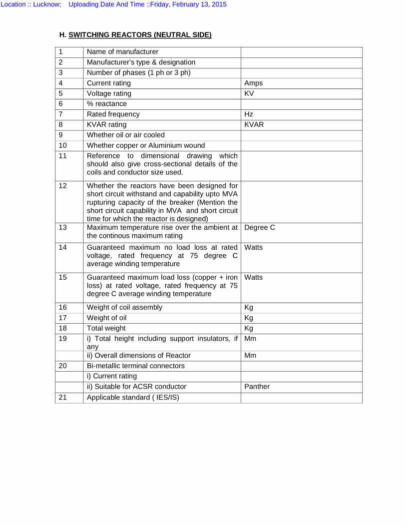
H. SWITCHING REACTORS (NEUTRAL SIDE) 1 Name of manufacturer 2 Manufacturer’s type & designation 3 Number of phases (1 ph or 3 ph) 4 Current rating Amps 5 Voltage rating KV 6 % reactance 7 Rated frequency Hz 8 KVAR rating KVAR 9 Whether oil or air cooled 10 Whether copper or Aluminium wound 11 Reference to dimensional drawing which
should also give cross-sectional details of the coils and conductor size used.
12 Whether the reactors have been designed for short circuit withstand and capability upto MVA rupturing capacity of the breaker (Mention the short circuit capability in MVA and short circuit time for which the reactor is designed)
13 Maximum temperature rise over the ambient at the continous maximum rating
Degree C
14 Guaranteed maximum no load loss at rated voltage, rated frequency at 75 degree C average winding temperature
Watts
15 Guaranteed maximum load loss (copper + iron loss) at rated voltage, rated frequency at 75 degree C average winding temperature
Watts
16 Weight of coil assembly Kg 17 Weight of oil Kg 18 Total weight Kg 19 i) Total height including support insulators, if
any Mm
ii) Overall dimensions of Reactor Mm 20 Bi-metallic terminal connectors i) Current rating ii) Suitable for ACSR conductor Panther 21 Applicable standard ( IES/IS)
Location :: Lucknow; Uploading Date And Time ::Friday, February 13, 2015

SCHEDULE-R-13 (A)
GUARANTEED TECHNICAL PARTICULARS OF 1.1 KV FRLS PVC UNARMOURED COPPER CONTROL CABLE
S.No. Particulars Size of Cable 2x2.5 sq.
mm.
4x2.5 sq.
mm.
6x2.5 sq.
mm.
1. Name of manufacturer/make 2. Type of cable. 3. Cable Type
a) Size. b) Standard applicable. c) Voltage rating.
Location :: Lucknow; Uploading Date And Time ::Friday, February 13, 2015
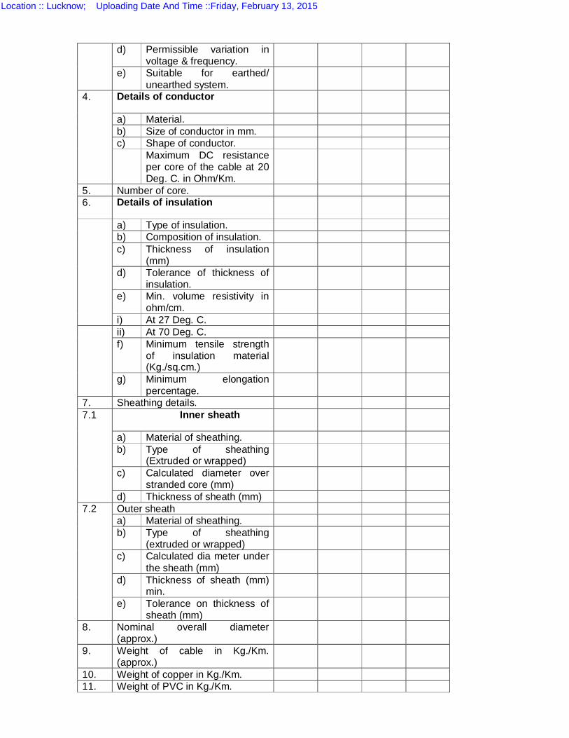
d) Permissible variation in voltage & frequency.
e) Suitable for earthed/ unearthed system.
4. Details of conductor
a) Material. b) Size of conductor in mm. c) Shape of conductor. Maximum DC resistance
per core of the cable at 20 Deg. C. in Ohm/Km.
5. Number of core. 6. Details of insulation
a) Type of insulation. b) Composition of insulation. c) Thickness of insulation
(mm)
d) Tolerance of thickness of insulation.
e) Min. volume resistivity in ohm/cm.
i) At 27 Deg. C. ii) At 70 Deg. C.
f) Minimum tensile strength of insulation material (Kg./sq.cm.)
g) Minimum elongation percentage.
7. Sheathing details. 7.1 Inner sheath
a) Material of sheathing. b) Type of sheathing
(Extruded or wrapped)
c) Calculated diameter over stranded core (mm)
d) Thickness of sheath (mm) 7.2 Outer sheath
a) Material of sheathing. b) Type of sheathing
(extruded or wrapped)
c) Calculated dia meter under the sheath (mm)
d) Thickness of sheath (mm) min.
e) Tolerance on thickness of sheath (mm)
8. Nominal overall diameter (approx.)
9. Weight of cable in Kg./Km. (approx.)
10. Weight of copper in Kg./Km. 11. Weight of PVC in Kg./Km.
Location :: Lucknow; Uploading Date And Time ::Friday, February 13, 2015

12. Standard specification to which the cable will conform.
13. Standard drum length of cable in Mtrs. to be supplied.
14. Current rating of cable under basic assumption as per IS : 3961
a) Laid in ground temp. 300C b) Laid in duct temp. 300C
c) Laid in air temp. 400C 15. Rating factor under various
conditions of insulation.
16. Minimum bending radius. 17. Short circuit withstand capacity
for duration of (in KA)
i) 1 sec. ii) 3 sec.
18. Insulation resistance at 270C (Mega Ohms per Km.)
19. Capacitive reactance per Km. of Cable.
20. Inductive reactance per Km. of Cable.
21. Weight of drum. 22. Particulars of drum (Inside
dimensions) in mm.
a) Flange b) Barrel c) Traverse
23. Reference of standard in respect of cores.
24. Reference of standard to which the drum conform.
25. Reference to standard in respect of cables.
26. Reference of license to use ISI certification mark.
Location :: Lucknow; Uploading Date And Time ::Friday, February 13, 2015
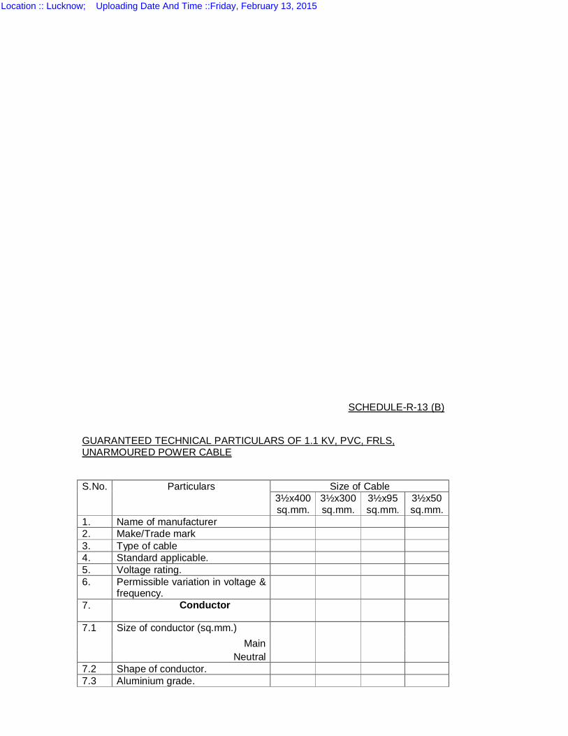
SCHEDULE-R-13 (B)
GUARANTEED TECHNICAL PARTICULARS OF 1.1 KV, PVC, FRLS, UNARMOURED POWER CABLE
S.No. Particulars Size of Cable
3½x400 sq.mm.
3½x300 sq.mm.
3½x95 sq.mm.
3½x50 sq.mm.
1. Name of manufacturer 2. Make/Trade mark 3. Type of cable 4. Standard applicable. 5. Voltage rating. 6. Permissible variation in voltage &
frequency.
7. Conductor
7.1 Size of conductor (sq.mm.) Main
Neutral 7.2 Shape of conductor. 7.3 Aluminium grade.
Location :: Lucknow; Uploading Date And Time ::Friday, February 13, 2015
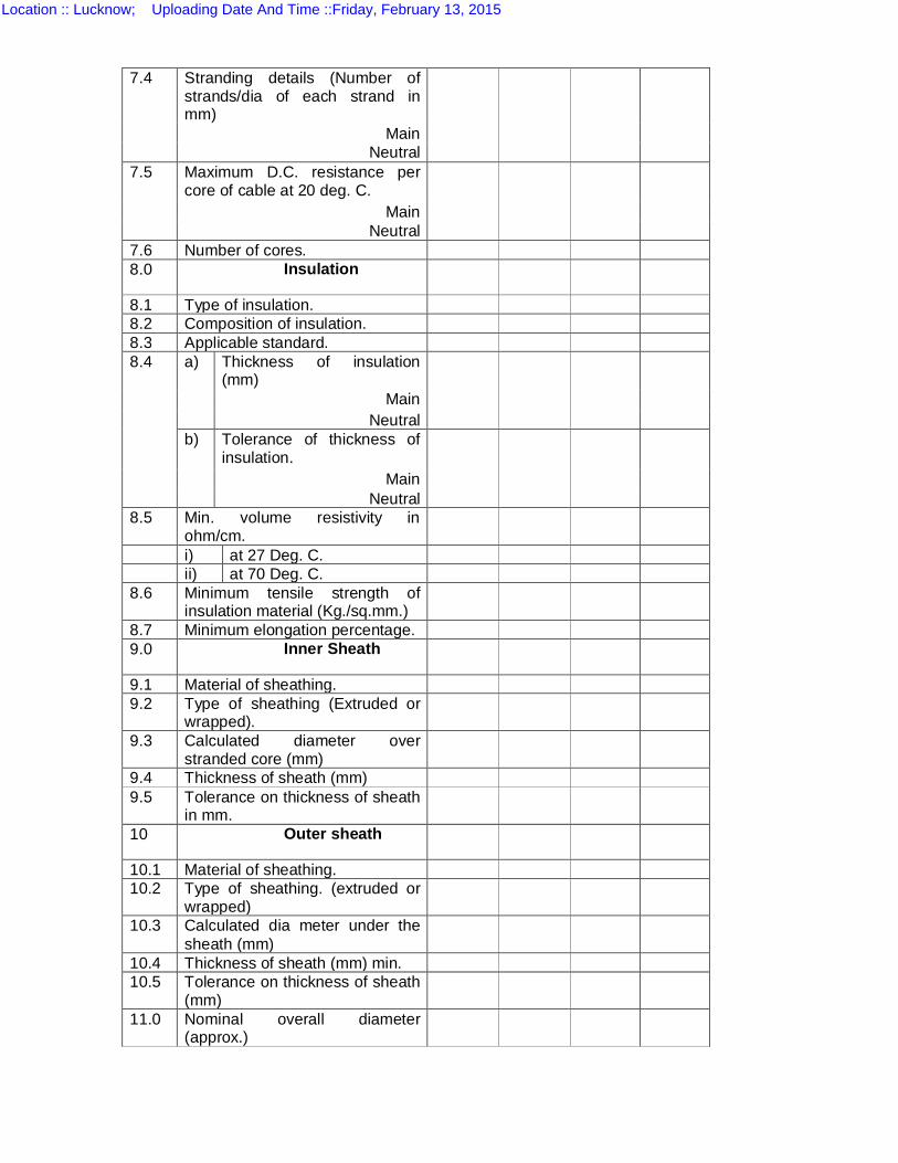
7.4 Stranding details (Number of strands/dia of each strand in mm)
Main Neutral
7.5 Maximum D.C. resistance per core of cable at 20 deg. C.
Main Neutral
7.6 Number of cores. 8.0 Insulation
8.1 Type of insulation. 8.2 Composition of insulation. 8.3 Applicable standard. 8.4 a) Thickness of insulation
(mm)
Main Neutral
b) Tolerance of thickness of insulation.
Main Neutral
8.5 Min. volume resistivity in ohm/cm.
i) at 27 Deg. C. ii) at 70 Deg. C. 8.6 Minimum tensile strength of
insulation material (Kg./sq.mm.)
8.7 Minimum elongation percentage. 9.0 Inner Sheath
9.1 Material of sheathing. 9.2 Type of sheathing (Extruded or
wrapped).
9.3 Calculated diameter over stranded core (mm)
9.4 Thickness of sheath (mm) 9.5 Tolerance on thickness of sheath
in mm.
10 Outer sheath
10.1 Material of sheathing. 10.2 Type of sheathing. (extruded or
wrapped)
10.3 Calculated dia meter under the sheath (mm)
10.4 Thickness of sheath (mm) min. 10.5 Tolerance on thickness of sheath
(mm)
11.0 Nominal overall diameter (approx.)
Location :: Lucknow; Uploading Date And Time ::Friday, February 13, 2015

12.0 Current rating of cable under basic assumption as per IS : 3961-1967.
a) Laid in & round temp. 300C
b) Laid in duct Temp. 300C c) Laid in air temp. 400C
13.0 Rating factor under various conditions of insulation
14.0 Short circuit withstand capacity in KA for i) 1 sec. ii) 3 sec.
15.0 Standard drum length of cable in Mtrs. to be supplied.
16.0 Weight of cable in Kg./Km. (approx.)
17.0 Weight of Aluminium Kg./Km. 18.0 Weight of PVC in Kg./Km. 19.0 Weight of drum Kg. 20.0 Particulars of drum (inside
dimensions) in mm.
a) Flange b) Barrel c) Traverse
21.0 Gross weight of drum including weight of cable.
22.0 Minimum bending radius. 23.0 Reference to standards in
respect of cables.
24.0 Reference of standard in respect of cores.
25.0 Reference of standard in respect of drum.
26.0 Reference of license to use ISI certification mark, if any.
Location :: Lucknow; Uploading Date And Time ::Friday, February 13, 2015
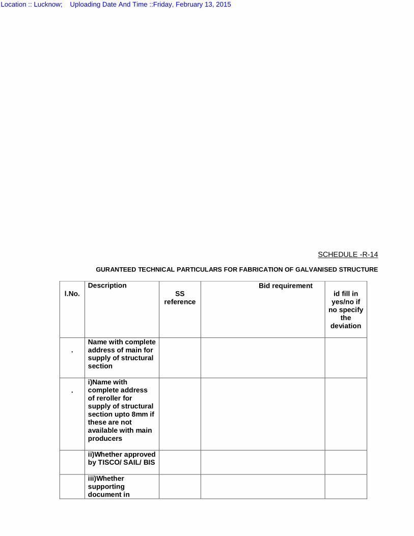
SCHEDULE -R-14
GURANTEED TECHNICAL PARTICULARS FOR FABRICATION OF GALVANISED STRUCTURE
l.No.
Description SS
reference
Bid requirement id fill in
yes/no if no specify
the deviation
.
Name with complete address of main for supply of structural section
.
i)Name with complete address of reroller for supply of structural section upto 8mm if these are not available with main producers
ii)Whether approved by TISCO/ SAIL/ BIS
iii)Whether supporting document in
Location :: Lucknow; Uploading Date And Time ::Friday, February 13, 2015
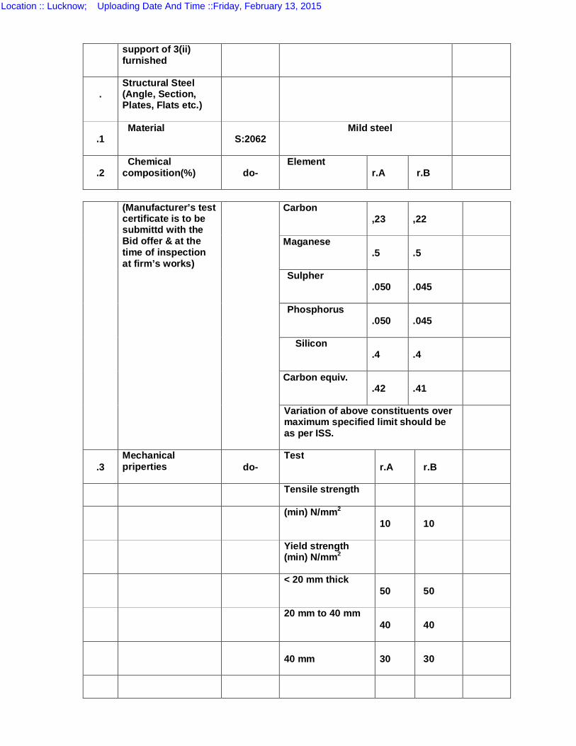
support of 3(ii) furnished
.
Structural Steel (Angle, Section, Plates, Flats etc.)
.1
Material S:2062 Mild steel
.2
Chemical composition(%)
do-
Element r.A
r.B
(Manufacturer’s test certificate is to be submittd with the Bid offer & at the time of inspection at firm’s works)
Carbon ,23
,22
Maganese .5
.5
Sulpher .050
.045
Phosphorus .050
.045
Silicon .4
.4
Carbon equiv. .42
.41
Variation of above constituents over maximum specified limit should be as per ISS.
.3
Mechanical priperties
do-
Test r.A
r.B
Tensile strength
(min) N/mm2 10
10
Yield strength (min) N/mm2
< 20 mm thick 50
50
20 mm to 40 mm 40
40
40 mm
30
30
Location :: Lucknow; Uploading Date And Time ::Friday, February 13, 2015
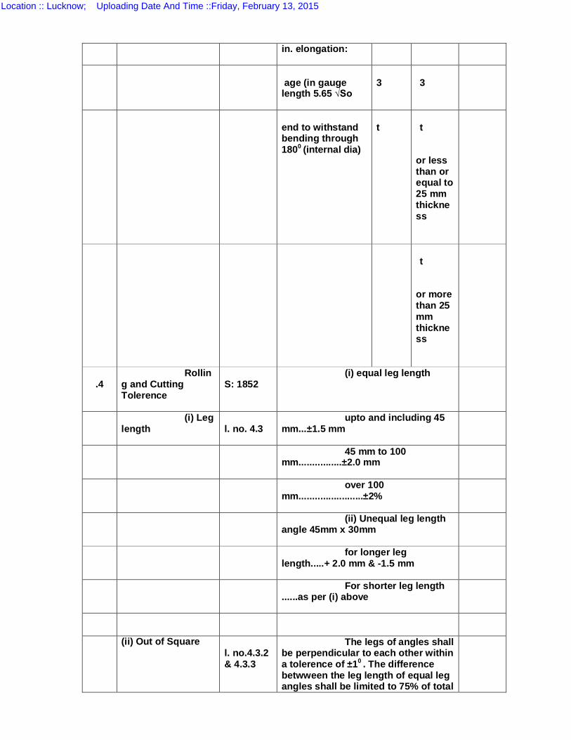
in. elongation:
age (in gauge length 5.65 √So
3
3
end to withstand bending through 1800 (internal dia)
t
t
or less than or equal to 25 mm thickness
t
or more than 25 mm thickness
.4
Rolling and Cutting Tolerence
S: 1852
(i) equal leg length
(i) Leg length
l. no. 4.3
upto and including 45 mm...±1.5 mm
45 mm to 100 mm................±2.0 mm
over 100 mm........................±2%
(ii) Unequal leg length angle 45mm x 30mm
for longer leg length.....+ 2.0 mm & -1.5 mm
For shorter leg length ......as per (i) above
(ii) Out of Square l. no.4.3.2 & 4.3.3
The legs of angles shall be perpendicular to each other within a tolerence of ±10 . The difference betwween the leg length of equal leg angles shall be limited to 75% of total
Location :: Lucknow; Uploading Date And Time ::Friday, February 13, 2015
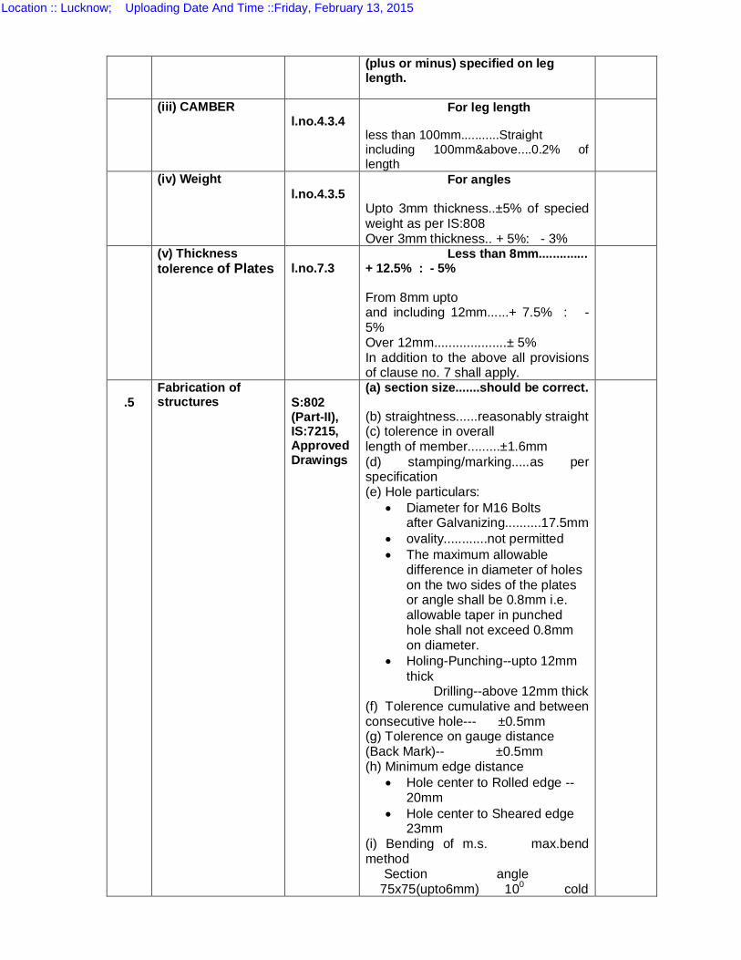
(plus or minus) specified on leg length.
(iii) CAMBER l.no.4.3.4
For leg length
less than 100mm...........Straight including 100mm&above....0.2% of length
(iv) Weight l.no.4.3.5
For angles
Upto 3mm thickness..±5% of specied weight as per IS:808 Over 3mm thickness.. + 5%: - 3%
(v) Thickness tolerence of Plates
l.no.7.3
Less than 8mm.............. + 12.5% : - 5%
From 8mm upto and including 12mm......+ 7.5% : -5% Over 12mm....................± 5% In addition to the above all provisions of clause no. 7 shall apply.
.5
Fabrication of structures
S:802 (Part-II), IS:7215, Approved Drawings
(a) section size.......should be correct.
(b) straightness......reasonably straight (c) tolerence in overall length of member.........±1.6mm (d) stamping/marking.....as per specification (e) Hole particulars:
Diameter for M16 Bolts after Galvanizing..........17.5mm
ovality............not permitted The maximum allowable
difference in diameter of holes on the two sides of the plates or angle shall be 0.8mm i.e. allowable taper in punched hole shall not exceed 0.8mm on diameter.
Holing-Punching--upto 12mm thick
Drilling--above 12mm thick (f) Tolerence cumulative and between consecutive hole--- ±0.5mm (g) Tolerence on gauge distance (Back Mark)-- ±0.5mm (h) Minimum edge distance
Hole center to Rolled edge --20mm
Hole center to Sheared edge 23mm
(i) Bending of m.s. max.bend method Section angle 75x75(upto6mm) 100 cold
Location :: Lucknow; Uploading Date And Time ::Friday, February 13, 2015
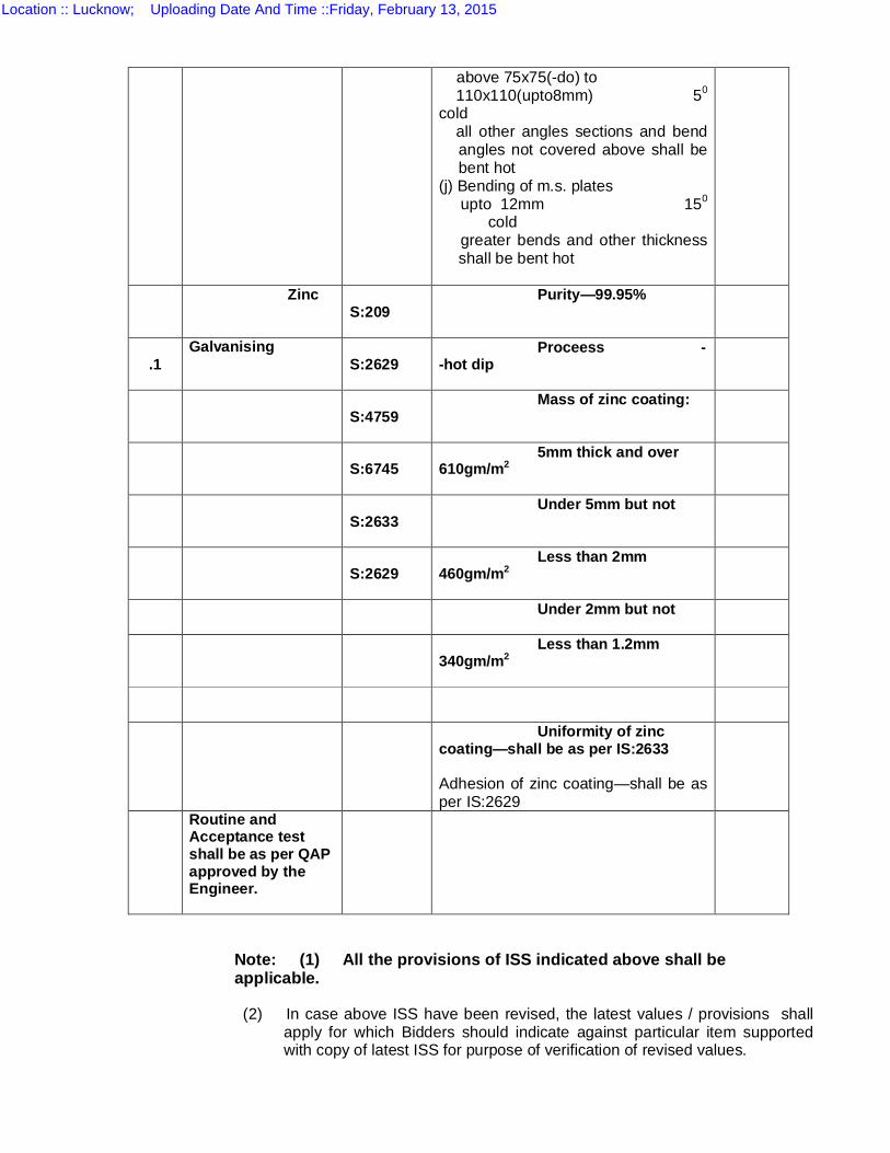
Note: (1) All the provisions of ISS indicated above shall be applicable.
(2) In case above ISS have been revised, the latest values / provisions shall apply for which Bidders should indicate against particular item supported with copy of latest ISS for purpose of verification of revised values.
above 75x75(-do) to 110x110(upto8mm) 50
cold all other angles sections and bend
angles not covered above shall be bent hot
(j) Bending of m.s. plates upto 12mm 150
cold greater bends and other thickness
shall be bent hot
Zinc S:209
Purity—99.95%
.1
Galvanising S:2629
Proceess --hot dip
S:4759
Mass of zinc coating:
S:6745
5mm thick and over 610gm/m2
S:2633
Under 5mm but not
S:2629
Less than 2mm 460gm/m2
Under 2mm but not
Less than 1.2mm 340gm/m2
Uniformity of zinc coating—shall be as per IS:2633
Adhesion of zinc coating—shall be as per IS:2629
Routine and Acceptance test shall be as per QAP approved by the Engineer.
Location :: Lucknow; Uploading Date And Time ::Friday, February 13, 2015
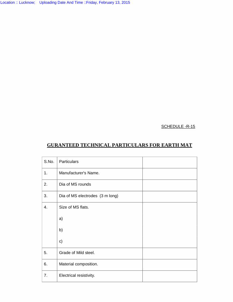
SCHEDULE -R-15
GURANTEED TECHNICAL PARTICULARS FOR EARTH MAT
S.No. Particulars
1. Manufacturer's Name.
2. Dia of MS rounds
3. Dia of MS electrodes (3 m long)
4. Size of MS flats.
a)
b)
c)
5. Grade of Mild steel.
6. Material composition.
7. Electrical resistivity.
Location :: Lucknow; Uploading Date And Time ::Friday, February 13, 2015
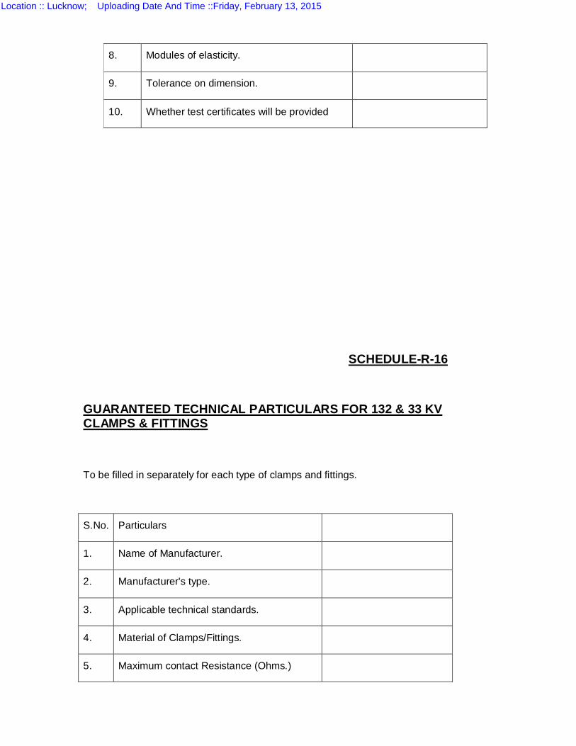
SCHEDULE-R-16
GUARANTEED TECHNICAL PARTICULARS FOR 132 & 33 KV CLAMPS & FITTINGS
To be filled in separately for each type of clamps and fittings.
S.No. Particulars
1. Name of Manufacturer.
2. Manufacturer's type.
3. Applicable technical standards.
4. Material of Clamps/Fittings.
5. Maximum contact Resistance (Ohms.)
8. Modules of elasticity.
9. Tolerance on dimension.
10. Whether test certificates will be provided
Location :: Lucknow; Uploading Date And Time ::Friday, February 13, 2015
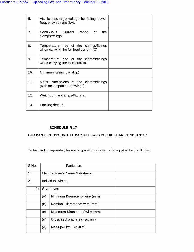
6. Visible discharge voltage for falling power frequency voltage (kV).
7. Continuous Current rating of the clamps/fittings.
8. Temperature rise of the clamps/fittings when carrying the full load current(0C).
9. Temperature rise of the clamps/fittings when carrying the fault current.
10. Minimum failing load (kg.)
11. Major dimensions of the clamps/fittings (with accompanied drawings).
12. Weight of the clamps/Fittings.
13. Packing details.
SCHEDULE-R-17
GUARANTEED TECHNICAL PARTICULARS FOR BUS BAR CONDUCTOR
To be filled in separately for each type of conductor to be supplied by the Bidder.
S.No. Particulars
1. Manufacturer's Name & Address.
2. Individual wires :
(i) Aluminum
(a) Minimum Diameter of wire (mm)
(b) Nominal Diameter of wire (mm)
(c) Maximum Diameter of wire (mm)
(d) Cross sectional area (sq.mm)
(e) Mass per km. (kg./Km)
Location :: Lucknow; Uploading Date And Time ::Friday, February 13, 2015
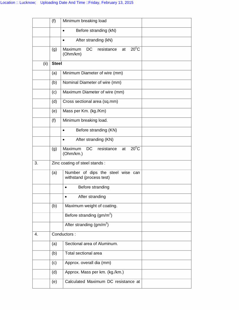
(f) Minimum breaking load
Before stranding (kN)
After stranding (kN)
(g) Maximum DC resistance at 200C (Ohm/km)
(ii) Steel
(a) Minimum Diameter of wire (mm)
(b) Nominal Diameter of wire (mm)
(c) Maximum Diameter of wire (mm)
(d) Cross sectional area (sq.mm)
(e) Mass per Km. (kg./Km)
(f) Minimum breaking load.
Before stranding (KN)
After stranding (KN)
(g) Maximum DC resistance at 200C (Ohm/km.)
3. Zinc coating of steel stands :
(a)
Number of dips the steel wise can withstand (process test)
Before stranding
After stranding
(b) Maximum weight of coating.
Before stranding (gm/m2)
After stranding (gm/m2)
4. Conductors :
(a) Sectional area of Aluminum.
(b) Total sectional area
(c) Approx. overall dia (mm)
(d) Approx. Mass per km. (kg./km.)
(e) Calculated Maximum DC resistance at
Location :: Lucknow; Uploading Date And Time ::Friday, February 13, 2015
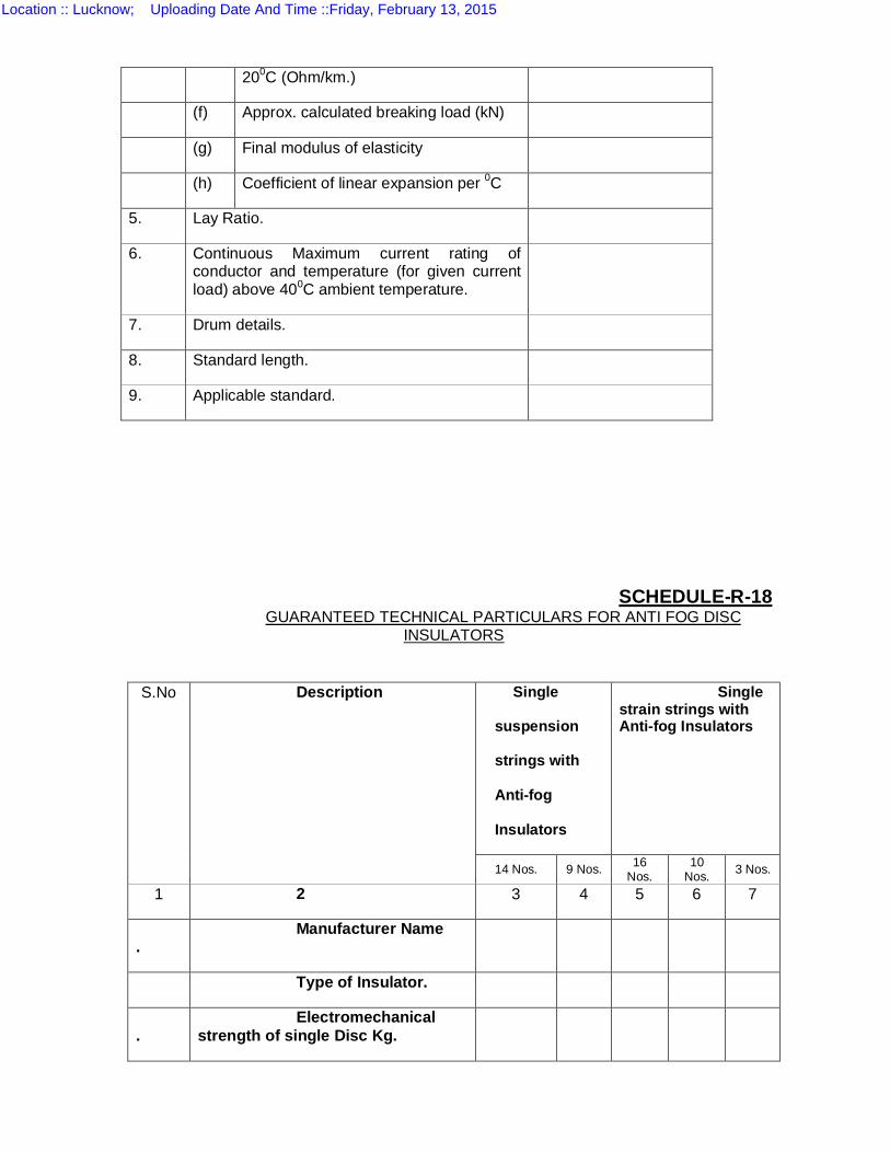
200C (Ohm/km.)
(f) Approx. calculated breaking load (kN)
(g) Final modulus of elasticity
(h) Coefficient of linear expansion per 0C
5. Lay Ratio.
6. Continuous Maximum current rating of conductor and temperature (for given current load) above 400C ambient temperature.
7. Drum details.
8. Standard length.
9. Applicable standard.
SCHEDULE-R-18
GUARANTEED TECHNICAL PARTICULARS FOR ANTI FOG DISC INSULATORS
S.No Description Single
suspension
strings with
Anti-fog
Insulators
Single strain strings with Anti-fog Insulators
14 Nos. 9 Nos. 16 Nos.
10 Nos. 3 Nos.
1 2 3 4 5 6 7
. Manufacturer Name
Type of Insulator.
. Electromechanical
strength of single Disc Kg.
Location :: Lucknow; Uploading Date And Time ::Friday, February 13, 2015
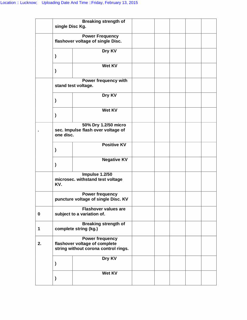
Breaking strength of single Disc Kg.
Power Frequency flashover voltage of single Disc.
)
Dry KV
)
Wet KV
Power frequency with stand test voltage.
)
Dry KV
)
Wet KV
. 50% Dry 1.2/50 micro
sec. Impulse flash over voltage of one disc.
)
Positive KV
)
Negative KV
Impulse 1.2/50 microsec. withstand test voltage KV.
Power frequency puncture voltage of single Disc. KV
0
Flashover values are subject to a variation of.
1
Breaking strength of complete string (kg.)
2.
Power frequency flashover voltage of complete string without corona control rings.
)
Dry KV
)
Wet KV
Location :: Lucknow; Uploading Date And Time ::Friday, February 13, 2015
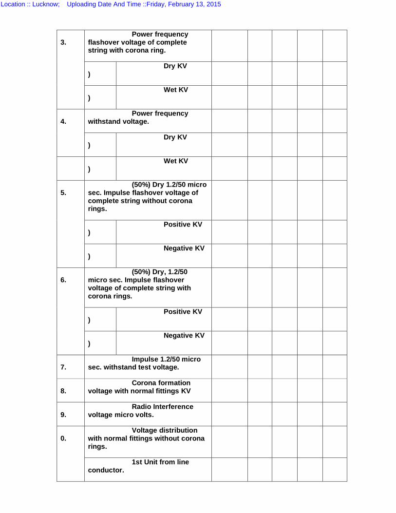
3.
Power frequency flashover voltage of complete string with corona ring.
)
Dry KV
)
Wet KV
4.
Power frequency withstand voltage.
)
Dry KV
)
Wet KV
5.
(50%) Dry 1.2/50 micro sec. Impulse flashover voltage of complete string without corona rings.
)
Positive KV
)
Negative KV
6.
(50%) Dry, 1.2/50 micro sec. Impulse flashover voltage of complete string with corona rings.
)
Positive KV
)
Negative KV
7.
Impulse 1.2/50 micro sec. withstand test voltage.
8.
Corona formation voltage with normal fittings KV
9.
Radio Interference voltage micro volts.
0.
Voltage distribution with normal fittings without corona rings.
1st Unit from line conductor.
Location :: Lucknow; Uploading Date And Time ::Friday, February 13, 2015
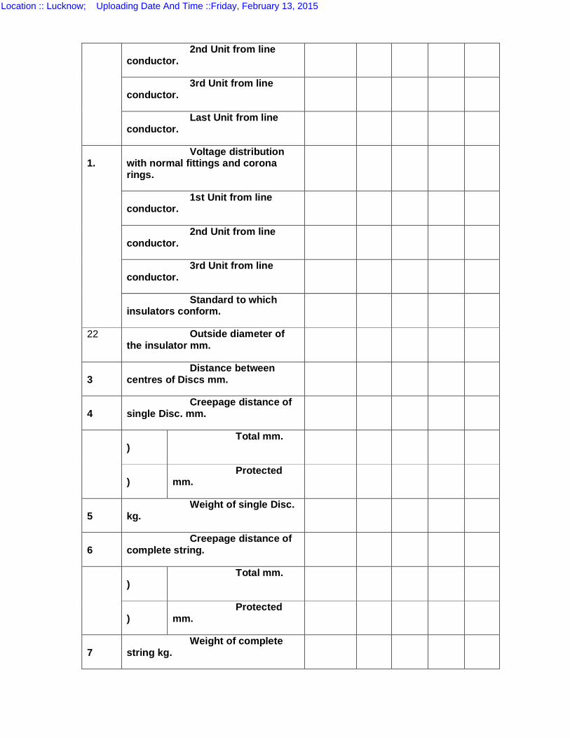
2nd Unit from line conductor.
3rd Unit from line conductor.
Last Unit from line conductor.
1.
Voltage distribution with normal fittings and corona rings.
1st Unit from line conductor.
2nd Unit from line conductor.
3rd Unit from line conductor.
Standard to which insulators conform.
22 Outside diameter of the insulator mm.
3
Distance between centres of Discs mm.
4
Creepage distance of single Disc. mm.
)
Total mm.
)
Protected mm.
5
Weight of single Disc. kg.
6
Creepage distance of complete string.
)
Total mm.
)
Protected mm.
7
Weight of complete string kg.
Location :: Lucknow; Uploading Date And Time ::Friday, February 13, 2015
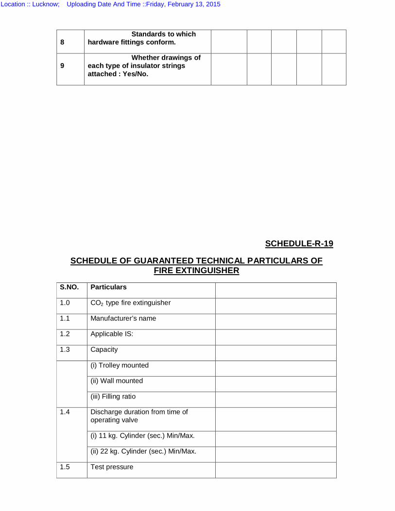
SCHEDULE-R-19
SCHEDULE OF GUARANTEED TECHNICAL PARTICULARS OF FIRE EXTINGUISHER
S.NO. Particulars
1.0 CO2 type fire extinguisher
1.1 Manufacturer’s name
1.2 Applicable IS:
1.3 Capacity
(i) Trolley mounted
(ii) Wall mounted
(iii) Filling ratio
1.4 Discharge duration from time of operating valve
(i) 11 kg. Cylinder (sec.) Min/Max.
(ii) 22 kg. Cylinder (sec.) Min/Max.
1.5 Test pressure
8
Standards to which hardware fittings conform.
9
Whether drawings of each type of insulator strings attached : Yes/No.
Location :: Lucknow; Uploading Date And Time ::Friday, February 13, 2015
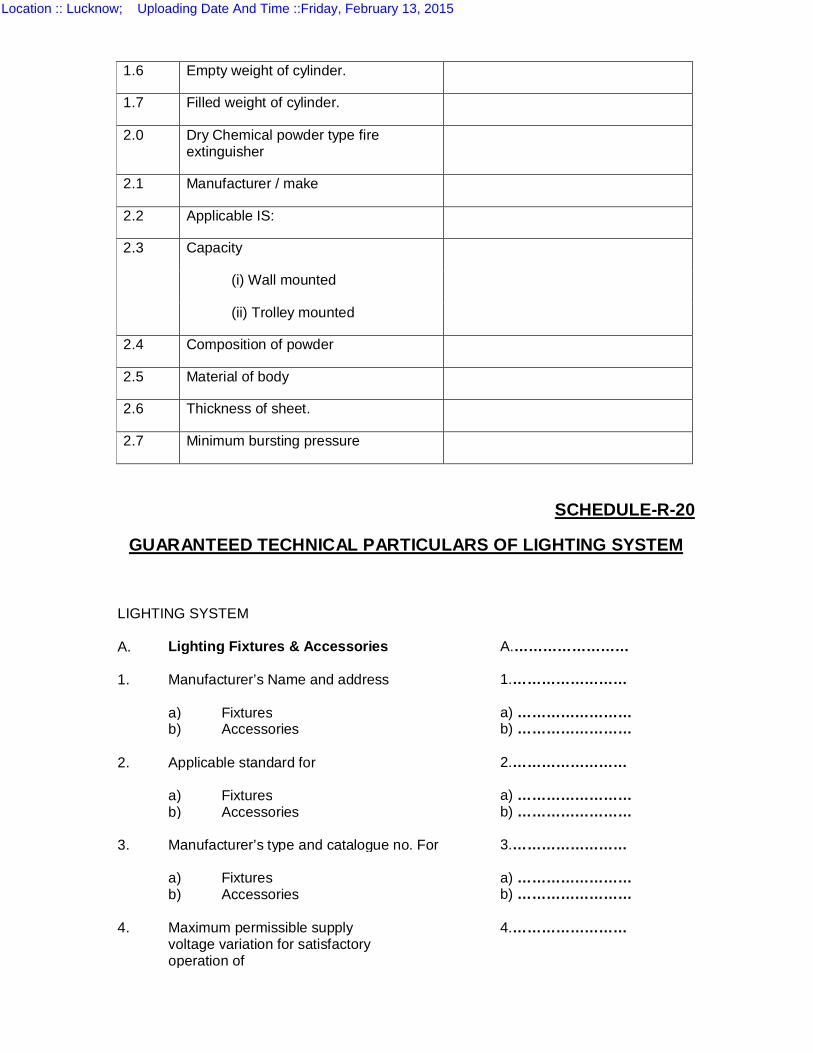
1.6 Empty weight of cylinder.
1.7 Filled weight of cylinder.
2.0 Dry Chemical powder type fire extinguisher
2.1 Manufacturer / make
2.2 Applicable IS:
2.3 Capacity
(i) Wall mounted
(ii) Trolley mounted
2.4 Composition of powder
2.5 Material of body
2.6 Thickness of sheet.
2.7 Minimum bursting pressure
SCHEDULE-R-20
GUARANTEED TECHNICAL PARTICULARS OF LIGHTING SYSTEM
LIGHTING SYSTEM A. Lighting Fixtures & Accessories A.…………………… 1. Manufacturer’s Name and address 1.…………………… a) Fixtures a) …………………… b) Accessories b) …………………… 2. Applicable standard for 2.…………………… a) Fixtures a) …………………… b) Accessories b) …………………… 3. Manufacturer’s type and catalogue no. For 3.…………………… a) Fixtures a) …………………… b) Accessories b) …………………… 4. Maximum permissible supply 4.…………………… voltage variation for satisfactory operation of
Location :: Lucknow; Uploading Date And Time ::Friday, February 13, 2015
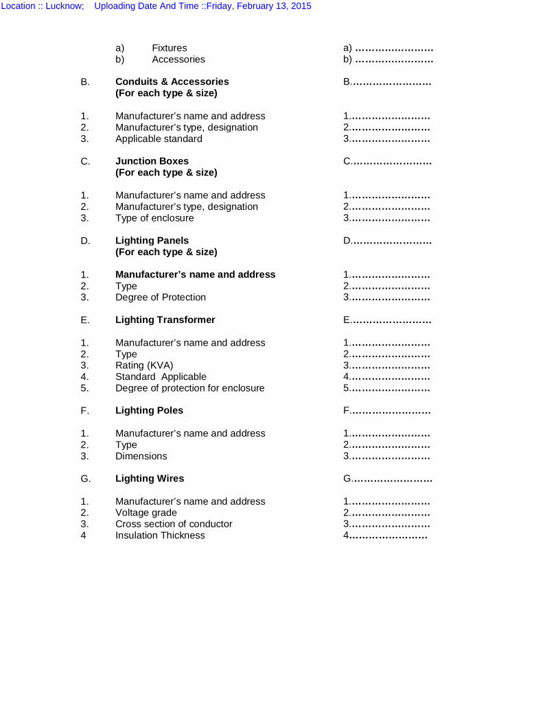
a) Fixtures a) …………………… b) Accessories b) …………………… B. Conduits & Accessories B.…………………… (For each type & size) 1. Manufacturer’s name and address 1.…………………… 2. Manufacturer’s type, designation 2.…………………… 3. Applicable standard 3.…………………… C. Junction Boxes C.…………………… (For each type & size) 1. Manufacturer’s name and address 1.…………………… 2. Manufacturer’s type, designation 2.…………………… 3. Type of enclosure 3.…………………… D. Lighting Panels D.…………………… (For each type & size) 1. Manufacturer’s name and address 1.…………………… 2. Type 2.…………………… 3. Degree of Protection 3.…………………… E. Lighting Transformer E.…………………… 1. Manufacturer’s name and address 1.…………………… 2. Type 2.…………………… 3. Rating (KVA) 3.…………………… 4. Standard Applicable 4.…………………… 5. Degree of protection for enclosure 5.…………………… F. Lighting Poles F.…………………… 1. Manufacturer’s name and address 1.…………………… 2. Type 2.…………………… 3. Dimensions 3.…………………… G. Lighting Wires G.…………………… 1. Manufacturer’s name and address 1.…………………… 2. Voltage grade 2.…………………… 3. Cross section of conductor 3.…………………… 4 Insulation Thickness 4……………………
Location :: Lucknow; Uploading Date And Time ::Friday, February 13, 2015
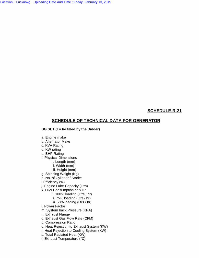
SCHEDULE-R-21
SCHEDULE OF TECHNICAL DATA FOR GENERATOR DG SET (To be filled by the Bidder) a. Engine make b. Alternator Make c. KVA Rating d. KW rating e. BHP Rating f. Physical Dimensions
i. Length (mm) ii. Width (mm) iii. Height (mm)
g. Shipping Weight (Kg) h. No. of Cylinder / Stroke i.Efficiency (%) j. Engine Lube Capacity (Ltrs) k. Fuel Consumption at NTP
i. 100% loading (Ltrs / hr) ii. 75% loading (Ltrs / hr) iii. 50% loading (Ltrs / hr)
l. Power Factor m. System back Pressure (KPA) n. Exhaust Flange o. Exhaust Gas Flow Rate (CFM) p. Compression Ratio q. Heat Rejection to Exhaust System (KW) r. Heat Rejection to Cooling System (KW) s. Total Radiated Heat (KW) t. Exhaust Temperature (°C)
Location :: Lucknow; Uploading Date And Time ::Friday, February 13, 2015
INSULATION
a. Manufacturer b. Acoustic lining material/density
VIBRATION ISOLATION SYSTEM
a. Manufacturer b. Type c. Deflection
PANEL
a. ACB b. Controller c. Meters d. Fuses
e. Load Manager
SECTION-VII
TECHNICAL SPECIFICATIONS OF
EQUIPMENTS AND MATERIAL
Location :: Lucknow; Uploading Date And Time ::Friday, February 13, 2015

TECHNICAL SPECIFICATIONS – INDEX
Sl.No.
Tech Specn. No.
ITEM
1. TS-1 A 20 MVA 132/33 KV TRANSFORMERS (not in scope) 2. TS-1 B 250 KVA 33/0.4 KV STATION TRANSFORMERS 3. TS-2 A 145 KV SF-6 CIRCUIT BREAKERS 4. TS-2 B 36 KV VACUUM CIRCUIT BREAKERS 5. TS-3 145 & 36KV CURRENT TRANSFORMERS 6. TS-4A 145 KV POTENTIAL TRANSFORMERS 7. TS-4B 36 KV POTENTIAL TRANSFORMERS 8. TS-5 A 145 KV Motorised ISOLATORS (as well as in GTP) 9. TS-5 B 36 KV Isolators 10. TS-6 145KV/36KV POST INSULATORS 11. TS-7 120 & 30 KVSURGE ARRESTORS 12. TS-8 CONTOL PANNEL SAS SYSTEM 13. TS-9 0.2 ACCURACY ABT TRIVECTOR ENERGY METERS 14. TS-10 A 110 V 200 AH BATTERIES 15. TS-10 B 110V 200 AH BATTERY CHARGER & DC DISTRIBUTION BOARD 16. TS-11 L T DISTRIBUTION BOARD 17. TS-12 33 KV 10MVAR CAP BANK 18. TS-13 CONTROL CABLE & POWER CABLE
Location :: Lucknow; Uploading Date And Time ::Friday, February 13, 2015
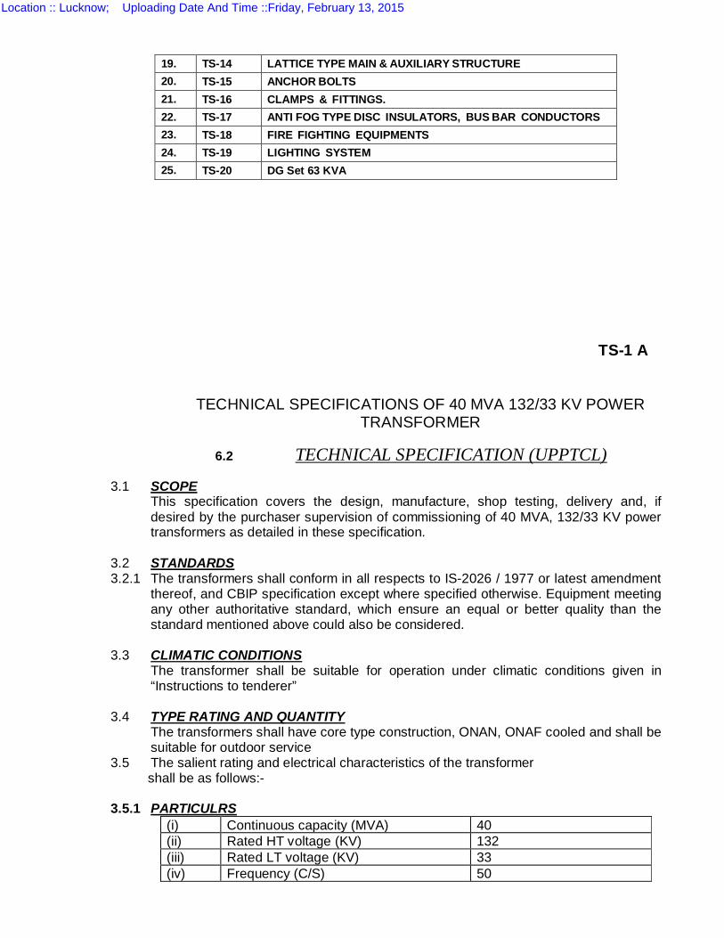
TS-1 A
TECHNICAL SPECIFICATIONS OF 40 MVA 132/33 KV POWER TRANSFORMER
6.2 TECHNICAL SPECIFICATION (UPPTCL)
3.1 SCOPE This specification covers the design, manufacture, shop testing, delivery and, if desired by the purchaser supervision of commissioning of 40 MVA, 132/33 KV power transformers as detailed in these specification.
3.2 STANDARDS 3.2.1 The transformers shall conform in all respects to IS-2026 / 1977 or latest amendment
thereof, and CBIP specification except where specified otherwise. Equipment meeting any other authoritative standard, which ensure an equal or better quality than the standard mentioned above could also be considered.
3.3 CLIMATIC CONDITIONS
The transformer shall be suitable for operation under climatic conditions given in “Instructions to tenderer”
3.4 TYPE RATING AND QUANTITY
The transformers shall have core type construction, ONAN, ONAF cooled and shall be suitable for outdoor service
3.5 The salient rating and electrical characteristics of the transformer shall be as follows:- 3.5.1 PARTICULRS
(i) Continuous capacity (MVA) 40 (ii) Rated HT voltage (KV) 132 (iii) Rated LT voltage (KV) 33 (iv) Frequency (C/S) 50
19. TS-14 LATTICE TYPE MAIN & AUXILIARY STRUCTURE 20. TS-15 ANCHOR BOLTS 21. TS-16 CLAMPS & FITTINGS. 22. TS-17 ANTI FOG TYPE DISC INSULATORS, BUS BAR CONDUCTORS 23. TS-18 FIRE FIGHTING EQUIPMENTS 24. TS-19 LIGHTING SYSTEM 25. TS-20 DG Set 63 KVA
Location :: Lucknow; Uploading Date And Time ::Friday, February 13, 2015
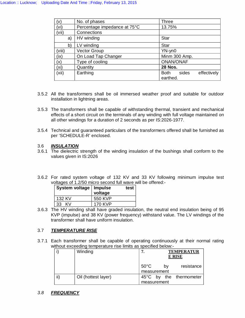
(v) No. of phases Three (vi) Percentage impedance at 75°C 13.75% (vii) Connections a) HV winding Star b) LV winding Star (viii) Vector Group YN-yn0 (ix) On Load Tap Changer Minm 300 Amp. (x) Type of cooling ONAN/ONAF (xi) Quantity 28 Nos. (xii) Earthing Both sides effectively
earthed.
3.5.2 All the transformers shall be oil immersed weather proof and suitable for outdoor installation in lightning areas.
3.5.3 The transformers shall be capable of withstanding thermal, transient and mechanical
effects of a short circuit on the terminals of any winding with full voltage maintained on all other windings for a duration of 2 seconds as per IS:2026-1977.
3.5.4 Technical and guaranteed particulars of the transformers offered shall be furnished as
per ‘SCHEDULE-R’ enclosed. 3.6 INSULATION 3.6.1 The dielectric strength of the winding insulation of the bushings shall conform to the
values given in IS:2026 3.6.2 For rated system voltage of 132 KV and 33 KV following minimum impulse test
voltages of 1.2/50 micro second full wave will be offered:- System voltage Impulse test
voltage 132 KV 550 KVP 33 KV 170 KVP
3.6.3 The HV winding shall have graded insulation, the neutral end insulation being of 95 KVP (impulse) and 38 KV (power frequency) withstand value. The LV windings of the transformer shall have uniform insulation.
3.7 TEMPERATURE RISE 3.7.1 Each transformer shall be capable of operating continuously at their normal rating
without exceeding temperature rise limits as specified below:- i) Winding 7. TEMPERATUR
E RISE
50°C by resistance measurement
ii) Oil (hottest layer) 45°C by the thermometer measurement
3.8 FREQUENCY
Location :: Lucknow; Uploading Date And Time ::Friday, February 13, 2015
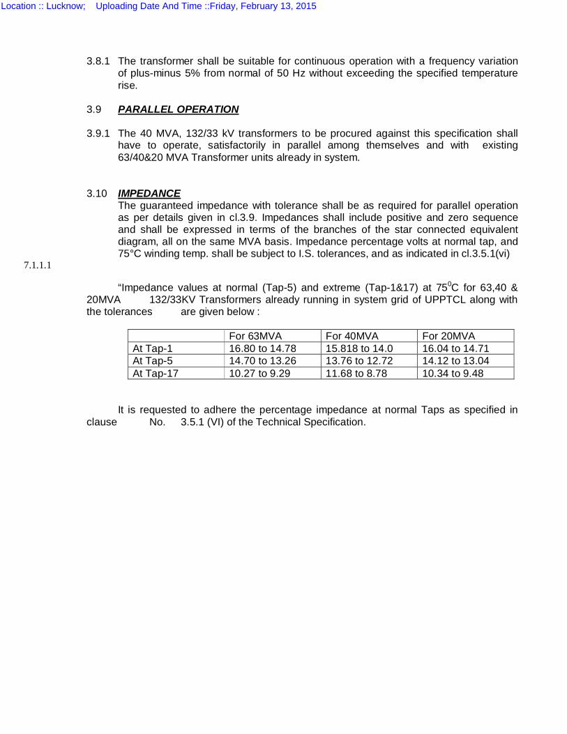
3.8.1 The transformer shall be suitable for continuous operation with a frequency variation
of plus-minus 5% from normal of 50 Hz without exceeding the specified temperature rise.
3.9 PARALLEL OPERATION 3.9.1 The 40 MVA, 132/33 kV transformers to be procured against this specification shall
have to operate, satisfactorily in parallel among themselves and with existing 63/40&20 MVA Transformer units already in system.
3.10 IMPEDANCE
The guaranteed impedance with tolerance shall be as required for parallel operation as per details given in cl.3.9. Impedances shall include positive and zero sequence and shall be expressed in terms of the branches of the star connected equivalent diagram, all on the same MVA basis. Impedance percentage volts at normal tap, and 75°C winding temp. shall be subject to I.S. tolerances, and as indicated in cl.3.5.1(vi)
7.1.1.1
“Impedance values at normal (Tap-5) and extreme (Tap-1&17) at 750C for 63,40 & 20MVA 132/33KV Transformers already running in system grid of UPPTCL along with the tolerances are given below :
For 63MVA For 40MVA For 20MVA At Tap-1 16.80 to 14.78 15.818 to 14.0 16.04 to 14.71 At Tap-5 14.70 to 13.26 13.76 to 12.72 14.12 to 13.04 At Tap-17 10.27 to 9.29 11.68 to 8.78 10.34 to 9.48
It is requested to adhere the percentage impedance at normal Taps as specified in clause No. 3.5.1 (VI) of the Technical Specification.
Location :: Lucknow; Uploading Date And Time ::Friday, February 13, 2015
3.11 MAXIMUM FLUX DENSITY
The maximum flux density in any part of the core and yoke at normal voltage and frequency, on normal tap shall not exceed 1.5 Tesla (15,000 lines per sq.cm).
3.12 TRANSFORMER LOSSES
3.12.1 The no load loss in kilowatt at rated voltage and rated frequency and the copper losses in kilowatts at rated output, rated voltage, rated frequency and at 75°C shall be guaranteed as under for each transformer.
i. Guaranteed No load loss at normal ratio, rated frequency and without any plus tolerance should not be more than 18.0 KW.
ii. Guaranteed Copper loss (Load Loss) at normal ratio, rated output rated voltage and rated frequency at 75°C average winding temperature without plus tolerance should not be more than 124.0 KW.
Firm should quote losses as mentioned above only. However firm may quote less loss as per their design which will be appreciated. Computation of capitalization will be done on the basis of losses fixed by UPPTCL as mentioned above. The offer of those firms, whose losses are more than the losses mentioned by UPPTCL, is likely to be rejected.
The rates of computation shall be :- i) Rs. 2,12,500.00 per KW of guaranteed no load loss ii) Rs. 86,700.00 per KW of guaranteed copper loss iii) Rs. 85,000.00 per KW of guaranteed auxiliary losses. The rates mentioned above may be revised as per current provision in CBIP and REC manual.
3.12.2 The penalties shall be separately evaluated from (i) the excess of the test figures of the no load loss over the corresponding guaranteed values @ Rs. 2,12,500.00 per KW, (ii) the excess of the test values of copper loss, over the corresponding guaranteed values @ Rs. 86700.00 per KW, (iii) the excess of test value of guaranteed auxiliary loss @ Rs. 85000.00 per KW.
It shall be at the discretion of purchaser to reject the transformers having losses in excess of guaranteed quoted value or accept them after having penalty as the above.
3.12.3 The contractor shall submit calculations along with relevant documents for no load losses, load losses and auxiliary losses.
3.13 COOLING 3.13.1 The transformers shall have ONAN and ONAF cooling. The transformers shall be
capable of giving a continuous output of at least 80% of their rating with only natural air (ONAN) cooling without exceeding the specified temperature rise limits.
3.13.2 The cooling arrangement shall consist of detachable radiators which should be directly mounted on the transformers. Connections between the radiators and tank shall be made with flanges provided with gaskets and an indicating shutoff valve provided at both connection ends, which can be fastened in open or closed position. Separate oil tight blank flange shall be provided for each tank connection for use when the radiator unit is detached.
Location :: Lucknow; Uploading Date And Time ::Friday, February 13, 2015

268
All radiators shall be completely interchangeable. Bottom of the radiators should be supported on angle frame also to reduce the oil leakage from radiators joints and distribute and mechanical load uniformly.
3.13.3 The radiators shall be so arranged that these can be detached from tank without disturbing the oil in the transformer. These shall be designed to withstand the vacuum and pressure specified for the tank. Radiators shall be so designed as to be accessible for cleaning & painting & to prevent accumulation of water on the outer surface to completely drain oil from the tank or bank & to ensure against formation of pockets when the tank is being filled.
All connections between the radiators and tank shall be provided with blank flange when the particular item is dispatched. Each radiator shall have a lifting eye and oil drain valve and vent at top.
3.13.4 Number of cooling fans for forced air cooling purposes must not be less than 8 running and 2 standby i.e. 4+1 in each group. Which shall be mounted on the frame connected with tank in such a manner, that no separate foundation work shall be required for the fans or the radiators or for the marshalling kiosk. Fans should be of High quality noise less and durable. These shall be readily accessible for inspection, maintenance or repairs. All the radiators shall be completely interchangeable. One No. standby cooling fan is to be required in both HV&LV side.
3.13.5 The fans for air blast cooling shall be so mounted that no damage to the coolers can arise from the vibration due to the operation of fans. Galvanized wire mesh screens shall be fitted to prevent accidental contact with the blades. The mesh being not greater than 2.5 cm.
3.14 COOLER CONTROL 3.14.1 Cooler scheme shall be suitable to operate with 440 volts 3 phase, 4 wire, 50
Hz external power supply with a voltage variation of + 10%. 3.14.2 A marshalling box cum cooler control cabinet of weather proof construction shall be provided for housing the control equipment of cooler scheme. This unit shall be provided with doors in the front as well as on the back. All the fittings, switches fuses and contactors etc. would be mounted on the front side of the marshalling box and the wiring shall be done from the back side.
The terminal blocks shall be provided in the side. The marshalling box shall be mounted on the transformers tank in such a manner that both the doors could be opened for operation or repairs etc. without any difficulty.
3.14.3 The cables between this unit and fans, W.T.I, O.T.I., buchholz relay etc. shall be provided by the tenderer. Cables should be of copper and 1.1 KV grade. It shall be complete with hinged doors, padlock arrangement, thermostatically controlled space heaters to prevent condensation, cubicle light and the terminal glands for the cables.
3.14.4 Cooler control scheme shall consist of the following equipments. i) A miniature circuit breaker for the incoming A.C. supply with
thermal overload and short circuit protections which will also initiate an alarm when this breaker trips
Location :: Lucknow; Uploading Date And Time ::Friday, February 13, 2015
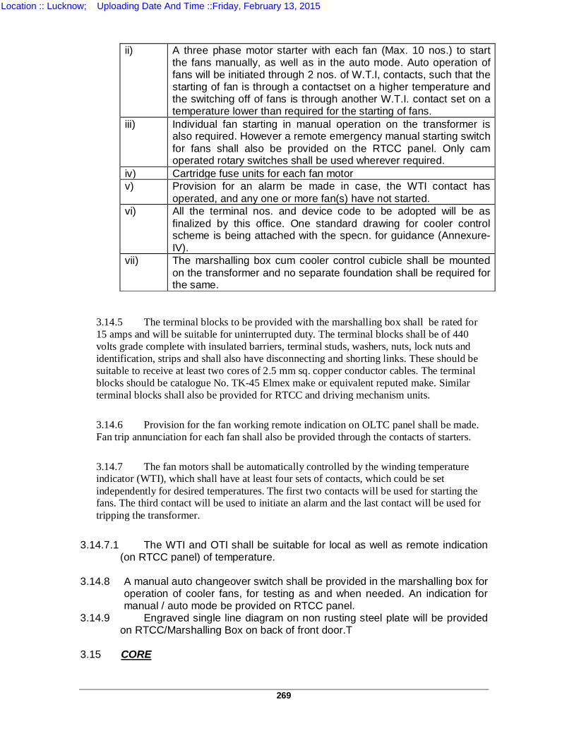
269
ii) A three phase motor starter with each fan (Max. 10 nos.) to start
the fans manually, as well as in the auto mode. Auto operation of fans will be initiated through 2 nos. of W.T.I, contacts, such that the starting of fan is through a contactset on a higher temperature and the switching off of fans is through another W.T.I. contact set on a temperature lower than required for the starting of fans.
iii) Individual fan starting in manual operation on the transformer is also required. However a remote emergency manual starting switch for fans shall also be provided on the RTCC panel. Only cam operated rotary switches shall be used wherever required.
iv) Cartridge fuse units for each fan motor v) Provision for an alarm be made in case, the WTI contact has
operated, and any one or more fan(s) have not started. vi) All the terminal nos. and device code to be adopted will be as
finalized by this office. One standard drawing for cooler control scheme is being attached with the specn. for guidance (Annexure-IV).
vii) The marshalling box cum cooler control cubicle shall be mounted on the transformer and no separate foundation shall be required for the same.
3.14.5 The terminal blocks to be provided with the marshalling box shall be rated for 15 amps and will be suitable for uninterrupted duty. The terminal blocks shall be of 440 volts grade complete with insulated barriers, terminal studs, washers, nuts, lock nuts and identification, strips and shall also have disconnecting and shorting links. These should be suitable to receive at least two cores of 2.5 mm sq. copper conductor cables. The terminal blocks should be catalogue No. TK-45 Elmex make or equivalent reputed make. Similar terminal blocks shall also be provided for RTCC and driving mechanism units.
3.14.6 Provision for the fan working remote indication on OLTC panel shall be made. Fan trip annunciation for each fan shall also be provided through the contacts of starters.
3.14.7 The fan motors shall be automatically controlled by the winding temperature indicator (WTI), which shall have at least four sets of contacts, which could be set independently for desired temperatures. The first two contacts will be used for starting the fans. The third contact will be used to initiate an alarm and the last contact will be used for tripping the transformer.
3.14.7.1 The WTI and OTI shall be suitable for local as well as remote indication
(on RTCC panel) of temperature. 3.14.8 A manual auto changeover switch shall be provided in the marshalling box for
operation of cooler fans, for testing as and when needed. An indication for manual / auto mode be provided on RTCC panel.
3.14.9 Engraved single line diagram on non rusting steel plate will be provided on RTCC/Marshalling Box on back of front door.T
3.15 CORE
Location :: Lucknow; Uploading Date And Time ::Friday, February 13, 2015
270
3.15.1 The core shall be built up with high-grade cold rolled non-aging, low loss, and high permeability grain oriented silicon steel laminations specially suitable, for transformer cores. The successful bidder shall have to produce the relevant documents towards use of proposed input materials of prime quality of CRGO as per the following details:
(a) Invoice of supplier; (b) Mills test certificate: (c) Packing list; (d) Certificate of origin: (e) Bill of lading; (f) Bill of entry certified by Custom Deportment;
Further, these materials shall be directly procured either from the mill or through their accredited marketing organization of repute and not through any agent.
3.15.2 After being sheared the lamination shall be treated to remove all burrs and
shall be re- annealed to remove all residual stresses. At least one side of each lamination shall be coated with an insulating coating as may be approved by the ISS and as per the modern manufacturing practice, which shall be inert to the action of hot transformer oil. The nature of insulation on core should be specified, in the tender.
3.15.3.1 The core shall be rigidly clamped or bolted to ensure adequate mechanical
strength and to prevent vibration during operation. The bolts used in the assembly of core shall be suitably insulated and clamping structure shall be so constructed that eddy currents will be minimum.
3.15.4 The core shall be provided with lugs suitable for lifting the complete core and
coil assembly of the transformer. 3.15.5 The core and the coil shall be so fixed in the tank that shifting does not occur
when the transformer is moved or during a short circuit.
3.16 WINDING 3.16.1 The winding shall be so designed that all coil assemblies of identical voltage
ratings shall be interchangeable and field repairs to the windings can be made readily without special equipment. The coil shall be supported between adjacent sections by insulating spacers and the barriers/ bracings etc. Insulation used in the assembly of the windings shall be arranged to ensure a free circulation of the oil and to reduce hot spot in the windings.
3.16.2 The coil shall be dried under vacuum and submerged in dried insulating oil to develop the
full electrical strength of the windings. All materials used in the insulation and assembly of the windings shall be insoluble, non catalytic, chemically inactive in the hot transformer oil, and shall not soften or otherwise be adversely affected under the operating conditions.
3.16.3 All threaded connections shall be provided with locking facilities. All leads from the winding to
the terminal board and bushings shall be rigidly supported to prevent injury from vibration. Guide tubes shall be used where practical.
Location :: Lucknow; Uploading Date And Time ::Friday, February 13, 2015
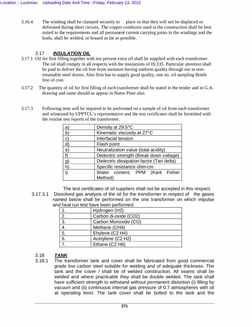
271
3.16.4 The winding shall be clamped securely in place so that they will not be displaced or
deformed during short circuits. The copper conductor used in the construction shall be best suited to the requirements and all permanent current carrying joints in the windings and the leads, shall be welded, or brazed as far as possible.
3.17 INSULATION OIL 3.17.1 Oil for first filling together with ten percent extra oil shall be supplied with each transformer.
The oil shall comply in all respects with the insulations of IS:335. Particular attention shall be paid to deliver the oil free from moisture having uniform quality through out in non-returnable steel drums. Also firm has to supply good quality, one no. oil sampling Bottle free of cost.
3.17.2 The quantity of oil for first filling of each transformer shall be stated in the tender and in G.A. drawing and same should as appear in Name Plate also.
3.17.3 Following tests will be required to be performed on a sample of oil from each transformer
and witnessed by UPPTCL’s representative and the test certificates shall be furnished with the routine test reports of the transformer.
a) Density at 29.5°C b) Kinematic viscosity at 27°C c) Interfacial tension d) Flash point e) Neutralization value (total acidity) f) Dielectric strength (Break down voltage) g) Dielectric dissipation factor (Tan delta) h) Specific resistance ohm-cm i) Water content, PPM (Karit Fisher
Method)
The test certificates of oil suppliers shall not be accepted in this respect. 3.17.3.1 Dissolved gas analysis of the oil for the transformer in respect of the gases
named below shall be performed on the one transformer on which impulse and heat run test have been performed.
1. Hydrogen (H2) 2. Carbon di-oxide (CO2) 3. Carbon Monoxide (CO) 4. Methane (CH4) 5. Ehylene (C2 H4) 6. Acetylene (C2 H2) 7. Ethane (C2 H6)
3.18 TANK 3.18.1 The transformer tank and cover shall be fabricated from good commercial
grade low carbon steel suitable for welding and of adequate thickness. The tank and the cover / shall be of welded construction. All seams shall be welded and where practicable they shall be double welded. The tank shall have sufficient strength to withstand without permanent distortion (i) filling by vacuum and (ii) continuous internal gas pressure of 0.7 atmospheres with oil at operating level. The tank cover shall be bolted to the tank and the
Location :: Lucknow; Uploading Date And Time ::Friday, February 13, 2015
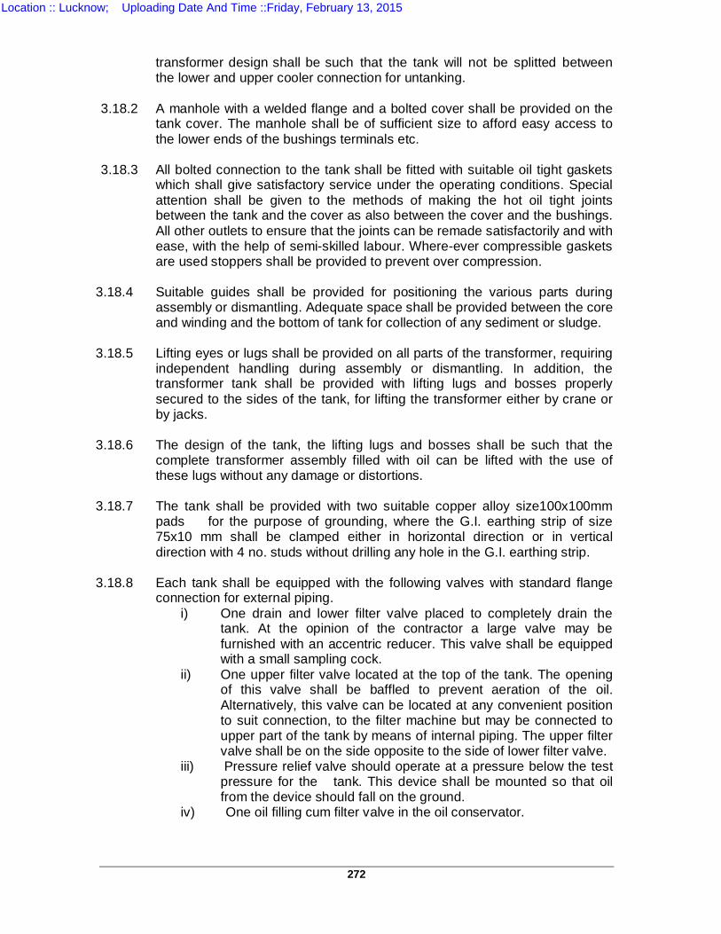
272
transformer design shall be such that the tank will not be splitted between the lower and upper cooler connection for untanking.
3.18.2 A manhole with a welded flange and a bolted cover shall be provided on the
tank cover. The manhole shall be of sufficient size to afford easy access to the lower ends of the bushings terminals etc.
3.18.3 All bolted connection to the tank shall be fitted with suitable oil tight gaskets
which shall give satisfactory service under the operating conditions. Special attention shall be given to the methods of making the hot oil tight joints between the tank and the cover as also between the cover and the bushings. All other outlets to ensure that the joints can be remade satisfactorily and with ease, with the help of semi-skilled labour. Where-ever compressible gaskets are used stoppers shall be provided to prevent over compression.
3.18.4 Suitable guides shall be provided for positioning the various parts during
assembly or dismantling. Adequate space shall be provided between the core and winding and the bottom of tank for collection of any sediment or sludge.
3.18.5 Lifting eyes or lugs shall be provided on all parts of the transformer, requiring
independent handling during assembly or dismantling. In addition, the transformer tank shall be provided with lifting lugs and bosses properly secured to the sides of the tank, for lifting the transformer either by crane or by jacks.
3.18.6 The design of the tank, the lifting lugs and bosses shall be such that the
complete transformer assembly filled with oil can be lifted with the use of these lugs without any damage or distortions.
3.18.7 The tank shall be provided with two suitable copper alloy size100x100mm
pads for the purpose of grounding, where the G.I. earthing strip of size 75x10 mm shall be clamped either in horizontal direction or in vertical direction with 4 no. studs without drilling any hole in the G.I. earthing strip.
3.18.8 Each tank shall be equipped with the following valves with standard flange
connection for external piping. i) One drain and lower filter valve placed to completely drain the
tank. At the opinion of the contractor a large valve may be furnished with an accentric reducer. This valve shall be equipped with a small sampling cock.
ii) One upper filter valve located at the top of the tank. The opening of this valve shall be baffled to prevent aeration of the oil. Alternatively, this valve can be located at any convenient position to suit connection, to the filter machine but may be connected to upper part of the tank by means of internal piping. The upper filter valve shall be on the side opposite to the side of lower filter valve.
iii) Pressure relief valve should operate at a pressure below the test pressure for the tank. This device shall be mounted so that oil from the device should fall on the ground.
iv) One oil filling cum filter valve in the oil conservator.
Location :: Lucknow; Uploading Date And Time ::Friday, February 13, 2015
273
3.18.9 There should be provision on PRV with dome on top on tank with tripping arrangement instead of explosion vent.
3.18.9.1 Air cell of best quality rubber (having no reaction with T/F oil) should be provided inside conservator tank to avoid oil contamination. 3.18.9.2 Supporting plate-form is to be provided for attending the Buchholz Relay, for its easy accessibility.
3.19 UNDERCARRIAGE 3.19.1 The transformer tank shall be supported on a structural steel base
equipment with forged steel or cast steel single flanged wheels suitable for moving the transformer completely filled with oil.
3.19.2 Jacking steps shall be provided. It shall be possible to change the direction
of the wheels through 90° when transformer is lifted on jacks to permit movement of the transformer both in longitudinal and transverse directions.
All the transformers shall have rail gauge of 1676.4 mm in both the directions.
3.19.3 Pulling eyes shall be provided to facilitate moving the transformer and they
shall be suitably braced in a vertical direction so that bending does not occur when the pull has a vertical component.
3.20 TAP CHANGING MECHANISM (40 MVA; 132/33 KV Transformer)
3.20.1 The transformer shall be provided with full capacity speed non inductive transition resistance type On load pattern taps on HV neutral end to vary voltage on LV side from –5% to + 15% in equal steps of 1.25% each i.e. 17 taps including one normal tap position. The tested ratios shall not have more than + 0.50% error from rated ratios on any of the 17 nos. of taps.
3.20.2 Tap changing mechanism shall be suitable for remote operation from RTCC
panel in the control room in addition to being capable of local manual as well as local electrical operation. OLTC gear shall be suitable for bi-directional flow of full power. Once the tap changing operation has been initiated it must be completed even if the supply to the driving mechanism interrupts. A 440 volt 3-phase 50 cycles external supply will be available for the operation of the changer. The supplier will provide an auxiliary 440 volts/55-0-55 volts transformer in the driving mechanism of the OLTC to operate the control scheme for the OLTC. Suitable audio as well as visual alarm shall be provided in case of failure of A.C. supply to OLTC cubicle.
3.20.3 The OLTC shall include the following:-
i) An oil immersed tap selector switch, which shall not interrupt the load current during tap change.
ii) Diverter switch with transition resistance iii) Separate compartment for diverter switch with independent oil conservator and
oil surge protective device
Location :: Lucknow; Uploading Date And Time ::Friday, February 13, 2015
274
iv) Motor driven mechanism v) Control & protection devices vi) Local tap changer position indicator. vii) Manual operating device.
3.20.3.1 The OLTC shall be properly type tested and OLTC of such vendors who
have got done type test on OLTC be accepted within five years. Reports of type/ Routine tests carried out on OLTC at vendor’s works has to be enclosed with final test report.
3.20.4 The on load tap changer shall be so designed that the contacts of tap
selector switch do not interrupt the arc. The diverter switch shall be located on separate oil filled compartment. The compartment shall be provided with means of releasing the gas produced by the arcing. It shall be designed so as to prevent the oil in the diverter switch compartment from mixing with the oil in the main tank or the tap selector.
3.20.5 The tap changer shall be capable of permitting parallel operation with other transformers of the same type covered by this specification, as well as, these already acquired by the purchaser (cl.3.9)
3.20.6 The transformers shall give full load output on all taps. The manual
operating device shall be so located on the transformer that it can be operated by a man standing at the level of the transformer track. It shall be strong and robust in construction, and all rotating parts and shafts shall be covered by protective caging or covering.
3.20.7 The control scheme for the tap changer shall be provided independent control of the tap changer when the transformers are in independent service. In addition, provision shall be made to enable parallel control also so that the tap changer will be operated simultaneously when one or more units are in parallel, so that under normal conditions the tap changer will not become out of step. For this each of the seventeen taps shall be matched with the taps of the follower transformer, and the odd and even tap matching scheme shall not be acceptable. Additional feature like master and follower as well as an audio visual indication during the operation of motor shall also be incorporated.
3.20.8 Necessary interlock blocking independent control when the units are in
parallel shall be provided. 3.20.9 Under abnormal conditions such as may occur if the contactor controlling
one tap changer gets stuck, the arrangement must be such as to switch off supply to the motor so that an out of step condition is limited to one tap difference only. Details of out of step protection provided for the taps should be furnished in the tender.
3.20.10 The contactors and associated gear for the tap change driving motors
shall be housed in a local kiosk mounted on the transformer. All devices except the OLTC motor shall operate on 55-0-55 volts A.C. supply only.
Location :: Lucknow; Uploading Date And Time ::Friday, February 13, 2015
275
3.20.11 Complete particulars of the tap changing gear including capacity of the
motor shall be stated in the tender. 3.20.12 Tap changers are not required to be suitable for automatic voltage
sensed operation. 3.20.13 The rated current of the tap changer shall not be less than 300Amps for
40 MVA transformers 3.21 REMOTE TAP CHANGER CONTROL PANEL (RTCC) 3.21.1 All tap changing control equipments shall be mounted on a separate
panel for each transformer which will also be quoted separately. This panel shall be complete with all necessary fittings, instrument wiring terminal blocks, cable glands, internal light etc. The panel should be self-supporting, made of sheet steel. It shall be completely vermin proof and arrangements to prevent ingress of vermin through cable entry holes or ventilation slots shall be provided. The panel shall be provided with doors opening at the centre on which nothing shall be mounted. The panel is required to be matched with existing panels of the purchaser of height 2250 mm and depth, which can be 500-700mm. The OLTC panel shall be of light grey colour corresponding to I.S. 631.
3.21.2 The tap changing scheme shall be such as to operate the steps of two or
more transformers in parallel simultaneously as well as independently as and when desired.
3.21.3 A sequence selector switch comprising of four positions shall be provided which will indicate whether the transformer is in independent, master, follower or in off position. The scheme will give step by step, tap changing operation. In the independent position it shall be possible to change the taps of any transformer independently. Any one transformer can be made ‘Master’ and on changing the taps of this transformer, the taps of all other follower units will change automatically with the master and it will not be possible to change the taps of the follower transformers, independently.
3.21.4 The OLTC control scheme shall be designed for 55-0-55 volts A.C. Necessary auxiliary transformers of 440/55-0-55 volts A.C. shall be supplied by the contractors. This auxiliary transformer shall be installed in the driving mechanism as per latest practice to ensure that no 440 or 230 V A.C. supply is taken into the RTCC panel except for the purpose of light and heater. The OLTC control scheme and the Master follower parallel operation shall be identical to the standard control scheme based on the recommendations of C.B.I.P codes and which has been adopted by the purchaser, in respect of the existing transformers of various other makes. The contractor shall ensure that terminal nos. and the device codes as adopted by the Purchaser shall be followed by the supplier. The tentative drawings for terminal block nos. for the RTCC driving mechanism and the alarm and annunciation scheme are attached for the guidance of the tenderer as Annexure No. V, VI & VII.
3.21.5 Following indications shall be provided on RTCC panel i) Fan running indication (red colour) one for each fan ii) Auto / manual indication for fan controls switch iii) 55-0-55 volts A.C. supply on (red colour) iv) Fault on indication lamp
v) OLTC motor protection switch open indication (green colour)
Location :: Lucknow; Uploading Date And Time ::Friday, February 13, 2015
276
vi) Tap change in progress(Amber colour with one
independent buzzer) vii) Tap position of transformer (digital indication) viii) Winding temp. indicator
ix) Oil temp. indicator 3.21.5.1 Following non trip flag indications with alarm shall be provided - i) Fan trip (separate flag for each fan) ii) M.C.B. for cooler control trip iii) A.C. supply to fans and tap changer fail iv) Main conservator oil level low
v) OLTC conservator oil level low vi) W.T.I. operated fans not started vii) Tap changer motor stuck viii)Taps not in synchronism (out of step) ix) 55-0-55 A.C. voltage low. x) Winding Temp.Alarm xi) OTI Alarm xii) Main Bucholz Alarm
3.21.5.2 Annunciations required on purchaser’s transformer control panel
The following flag indications are required to be passed on to the purchaser’s transformer control panel. The required terminal blocks for them shall be provided on the transformer marshalling box as per the attached drg. (Annexure IV).
a) TRIP ALARM i) Buchholz alarm ii) W.T.I. alarm iii) O.T.I. trip iv) Tap changer oil surge relay trip v) Pressure release device trip b) NON TRIP ALARM i) W.T.I. temp. high
ii) O.T.I. temp. high iii) Buchholz alarm 3.21.6.1 The alarm scheme should be such that it will be possible to silence the
alarm after its receipt and immediately after receipt; it shall be available for next operation. It should not however be possible to reset the flag unless the cause of the fault is removed.
3.21.6.2 There should be a provision of electronic Annunciation window instead of
mechanical relay for different indications at RTCC panel. 3.22 OIL PRESERVING EQUIPMENT 3.22.1 Oil preserving equipment shall be conservator. 3.22.2 The conservator shall have two filter valves, one at the bottom at one
end, the other at the top at opposite end and in addition to the valves specified in the accessories for the main tank. The conservator shall also have a shut off valve and a sump with a small drain valve and sampling
Location :: Lucknow; Uploading Date And Time ::Friday, February 13, 2015
277
cock, the later so arranged as not to interfere with oil lines. The magnetic oil level gauge shall be mounted on the conservator.
3.22.3 There shall also be an oil conservator for the OLTC which could either be
provided separately or a partition in the main conservator, with an independent M.O.L.G.
3.23.0 BUSHINGS
The following type of bushing shall be provided on the 40 MVA; 132/33 KV transformers. (i) HV 145 KV oil impregnated condenser type bushing of 800 Amps (ii) LV 36 KV plain porcelain oil communicating type bushings of 1000
Amps 3.23.1 The bushings shall be suitable for heavily polluted atmosphere (anti fog
type) and shall have high factors of safety against leakage to ground and shall be so located as to provide adequate electrical clearance between bushings and between the bushings and grounded parts. Bushings of identical voltage shall be interchangeable. All bushings shall be equipped with suitable terminals of approved type and size and all external current carrying contact surface shall be silver plated, adequately. The insulation class of the neutral bushing shall be properly coordinated with insulation class of the neutral end of the winding.
i) Each bushing shall be so coordinated with the transformer insulation that all flashovers will occur outside the tank.
ii) The porcelain used in bushings shall be of the wet process homogenous and free from cavities or other flaws. The glazing shall be uniform in colour and free from blisters burs and other defects.
iii) All bushings shall have puncture strength greater than, the dry flashover value. Special adjustable arcing horns are also to be provided for all bushings. All bushings shall comply with I.S. 2099.
iv) The tenderers are required to give the guaranteed withstand voltages for the above
bushings and also furnish a calibration curve with different settings of the coordination, gap
to the purchaser to decide the actual gap setting. Tenderers recommendations are also
invited in this respect.
v) The 132 KV bushings shall be condenser type and the 33 KV bushings shall be oil filled and these shall be identical to drawings attached as Annexure-VIII & IX.
vi) The minimum creepage distance of all the bushings shall not be less than 25 mm per KV of the max. system voltage as specified in clause 3.5 system particulars of this specification.
vii) The HV & LV bushings should be placed coinciding with the centre line of the transformer rollers.
3.24 CENTRE OF GRAVITY
The center of gravity of the transformer shall be low and as near to the vertical central line as possible. The transformer shall be stable with or
Location :: Lucknow; Uploading Date And Time ::Friday, February 13, 2015
278
without oil and radiators. If the center of gravity is accentric relative to track either with or without oil, its location shall be shown on the outline drawing.
3.25 ACCESSORIES 3.25.1 Each transformer shall be provided with the following accessories:-
i) A dial type indicating thermometer of robust pattern mounted inside the marshalling kiosk at a convenient height to read the temperature in the hottest part of the oil and fitted with the alarm and trip contacts with a repeater on RTCC panel to give oil temperature.
ii) A winding temperature indicator with repeater and alarm / trip fan starting contacts (08 nos.)
iii) Two magnetic type oil level gauge with low level alarm contact and a dial showing minimum; max. and normal oil level. The gauge shall be readable from the transformer base level.
iv) Two oil filling valve (in let) one for main conservator tank and one for OLTC conservator tank.
v) Two oil drain valves one from main conservator and other from OLTC conservator.
vi) One filter valve located at the top of the tank on one side vii) One filter valve located near the bottom of the tank on the other
side of transformer viii) Oil sampling valves for top, middle and bottom oil sample ix) Pressure release device of a safety valve of the chimney type with
an equalizer pipe interconnecting the top of the conservator and upper most part of the safety valve should be provided to permit rise of oil in the pipe. A stop cock should also be provided in the interconnecting pipe. An air release cock shall also be fitted in a convenient position. The safety valve pipe shall preferably take off from the side of the transformer tank near to the tank cover and not from the top of tank cover. In case if the pipe is taking off from the top of tank cover, arrangements shall be made to prevent, the gases forming in the tank from rising into the safety valve pipe and thereby by-passing the buchholz relay.
x) One double float English Electric or equivalent make type OBG M-3 E gas detector relay (buchholz relay) with alarm and tripping contacts to detect accumulation of gas and sudden change of pressure, complete with shut off valves on both the ends and flange couplings to permit easy removal without lowering oil level in the main tank or conservator, a bleed valve for gas venting, and a test valve.
xi) Heat exchangers or radiators with shut off valves at top and bottom. These will have lifting lugs and oil filling and drain plugs.
xii) An oil conservator for main tank as well as OLTC xiii) Cooling fans supported on the main tank or the radiators xiv) Eye bolts and lugs on all parts for ease of handling
xv) Oil surge relay for the OLTC diverter switch compartment. xvi) Two grounding pads suitable for 75x10 mm G.I. flat with four studs.
Location :: Lucknow; Uploading Date And Time ::Friday, February 13, 2015
279
3.25.1.1 Diagram and rating plate (for ease of identification at site and stores). It is desired that in addition to diagram and rating plate all equipments shall carry a metallic plate giving following information got marked by the manufacturers itself.
i) Name of equipment with specification No. ii) S.No. as per the bill of material iii) Year of order iv) Sl. No. of transformer
Guaranteed as well as measured values of percentage impedances and No load / Load losses / and Auxiliary losses without any plus tolerance at 75°C shall also be inscribed on the diagram and rating plate.
3.25.1.2 TERMINAL CLAMPS
Bimetallic terminal connectors for HV & LV: shall be suitable for ACSR PANTHER for 132 KV bushing and for 33 KV bushings the connectors shall be suitable for twin Moose ACSR conductor. All connectors should be suitable for horizontal as well vertical take off. Information shall be furnished by the tenderers for following items:
i) Material of clamps ii) Name of manufacturer
iii) Drawings of clamp iv) Weight of clamp
v) Metal of clamp vi) Testing facility for terminal connectors available at manufacturer’s work as per
relevant I.S. vii) Make of bolts, nuts and check nuts viii)Make of washers.
3.25.1.3 The tenderers are required to note that :-
i) 132 KV clamps should have atleast 2 pairs of bolts on conductor, as well as terminal end.
ii) The clamp should be designed with large factor of safety and should comply in all respects of temperature rise, resistance and short circuit current with stand capacity and other conditions specified in I.S. 5561-1970
iii) A check nut should be provided on each bolt to avoid loosening of nuts due to vibration etc and these should be hot dip galvanized.
iv) Bolts and nuts should be manufactured by a highly reputed concern.
v) The prices of clamps should be quoted separately.
3.25.2 The transformers shall be complete with marshalling box or kiosk in which all the leads from Buchholz relays, oil / winding temp., indicators and magnetic oil level gauges shall be brought out to suitable terminals. This kiosk shall be weather proof and vermin proof and shall be provided with a front door as well as a back door and mounted on the transformer on its side so that it will be possible to open both the doors during service. Engraved single line diagram on non rusting steel plate will be provided on RTCC/Marshalling Box on back of front door. The font side shall be used to mount all the fittings, fuses, switchgears and contactors etc., and the back side for the wiring. All the fixtures will
Location :: Lucknow; Uploading Date And Time ::Friday, February 13, 2015
280
be provided with a level plate in the front as well as in the back side for identification. The terminal blocks shall be provided in the side.
3.25.2.1 Necessary cable glands shall also be provided at the base of this kiosk. It
shall be complete with hinges and padlock arrangement, space heater, cubicle light, fuses etc. The necessary cables between transformer and the marshalling box shall also be provided by the tenderer.
3.25.3 The transformer shall also have a separate motor drive unit to
accommodate the motor drive for the OLTC along with the contractor’s relays and auxillary transformer etc., required for the operation of the OLTC. This will also be weather proof and vermin proof and shall be mounted on the transformer. Necessary cable glands, pad lock, space heater, light and protection devices shall be provided into it.
3.25.4 The equipment and accessories required with the transformer shall be
suitably mounted on the transformer for ease of operation, inspection and maintenance, and the mounting details shall be subject to the approval of the purchaser. All valves shall be provided either with blind companion flanges or with pipe lugs for protection.
3.25.5 Indication, alarm and relay equipment shall have contacts suitable for operation with 110 Volts D.C. supply.
3.25.6 Any fittings accessories of apparatus which might not have been mentioned in the specifications but which are usual and necessary in the equipment of similar design and are recommended by the manufacturer for satisfactory operation are to be provided by the contractor without extra cost. All apparatus must be complete in all details whether mentioned in the specification or not.
3.26 PAINTING 3.26.1 Before dispatch, all steel surfaces, not under oil, shall be painted with a
primary coat of anti-corrosive paint of durable nature and final two coats of light grey shade corresponding to IS: 631 paint of best quality. The interior surface shall be painted according to the contractor’s standard practice/ provision in ISS.
3.27 PACKING 3.27.1 The packing may be in accordance with the tenderers standard practice
so as to ensure safe transit by goods train or road. Special arrangements should be made to facilitate handling and to protect the projecting parts against damage in transit.
3.27.2 The transformer shall be dispatched filled with oil or if necessary with insert gas with a pressure gauge and a spare gas cylinder to replenish the gas pressure in transit or during its storage at the destination until it is filled up with oil.
3.27.3 All parts shall be adequately marked to facilitate identification and erection. Boxes and crates shall be marked with the tender specns. No. and shall have a packing list enclosed showing the parts contained therein.
3.27.4 Bill of Material: The supplier shall make available a consolidated bill of material for one transformer unit complete in all respects required as per cl.2.6.3 of
Location :: Lucknow; Uploading Date And Time ::Friday, February 13, 2015
281
General Requirements of Specifications. The bill shall be made out on drg. of A-3 size giving a serial no. for each item of fitting and accessories required for one transformer, and this no. shall be mentioned in the packing list and the challan to facilitate the cross checking of all the items by the consignees and to ensure that all the components of the transformer unit have been received.
3.28 FACTORY ASSEMBLY AND TEST 3.28.1 (a)Stage inspection:
Purchaser shall have the option to depute their representative to check the progress during any stage of manufacturing of each transformer. However, following will be hold points where the bidder will have to offer advance inspection call notice.
i) CORE: Thickness of laminations, overall height, width, window height & width ,cross section area & flux density
ii) COIL : ID,OD of HV, LV & Regulating windings, cross sectional area of copper conductor used, number of turns, their parallel conductors &calculation of copper used in manufacture of transformer. iii) TANK : Physical dimensions, thickness of bottom, sides, radiators and conservator tank sheet. Weight of tank. Vacuum and pressure test .
(b) Final inspection: The transformers shall be completely assembled and tested at the factory. If the
purchaser selects to send a representative, all tests shall be witnessed by him. Tests shall be
performed in compliance with I S 2026-1977 or latest amendment thereof.
3.28.2 The following tests shall be made on transformers :- i) All double welds shall be tested for leaks with dry nitrogen at a
pressure not less than 0.7 kg/sq. cms. (atmosphere) ii) All tanks, single welds, cooling coils, radiators, valves and other
parts necessary for complete transformer shall be tested for leak and strength by applying to the completed tank filled with oil an air pressure not less than 0.7 atmosphere for a period of 24 hours or not less than 1.0. Atmospheres for a period of six hrs. If leaks occur, the tests shall be conducted again till all leaks have been stopped.
iii) Routine tests as per IS-2026-1977 or its latest amendment iv) Temperature rise test on one unit as per IS:2026-1977.
v) Impulse test on all limbs of HV & LV windings of one unit as per CI.13 of IS-2026-1977.
vi) Zero phase sequence impedance measurement on each Transformer.
vii) Regulation at rated load at 1.0, 0.9, 0.8 lagging power factor (calculated)
Location :: Lucknow; Uploading Date And Time ::Friday, February 13, 2015
282
viii) Exciting current at 90%, 100%, 110% and 120% of rated
voltage ix) Excitation losses at 90, 100, 110 and 120% percent of rated
voltage measured by the average voltmeter method. x) Magnetic balance test on HV/LV winding on all the transformer xi) Exciting current measurement on both the HV/LV winding of all
the transformer at 440 Volts. xii) Ten Delta Test
3.29 TEST AT SITE 3.29.1 After erection at site, the purchaser shall carry out the following tests on
transformers:- i) Insulation resistance test
ii) Ratio and polarity test iii) Di-electric test on oil.
3.30 FURTHER TESTS 3.30.1 SHORT CIRCUIT TEST:
If UPPTCL desires, short circuit test at CPRI, Banglore/Bhopal may be carried out on any unit randomly selected for short circuit test. Firm will make all necessary arrangements for above test, expenditure on above will be reimbursed by department on actual basis.
3.30.2 The purchaser reserves the right of having other reasonable tests carried out at his own expense either before dispatch or at site to ensure that the transformer complies with the requirements of these specifications. The transformers shall be dispatch only after issue of dispatch authorization. In case the transformer dispatched without proper dispatch authorization, penalty will be deducted on the basis the date of issue of dispatch authorization and transit period. In this context no correspondence will be entertained.
3.31 After all tests have been completed, six certified copies of each test
report shall be furnished. Each report shall have following information:- i) Complete identification data including serial no. of the transformer ii) Method of application, where applied, duration, and interpretation
of results for each test. iii) Losses / Impedance corrected to 75°C 3.32 Drawings and instructions book for erection, commissioning,
operation and maintenance manual to be furnished by the supplier On placement of the order, the manufacturer shall supply three copies of all the drgs., which will describe the equipments in detail as per the provisions of cl.2.6. of the General Requirements of Specifications for approval.
3.32.1 Drawings
Location :: Lucknow; Uploading Date And Time ::Friday, February 13, 2015
283
All the drawings are required to be furnished in A-3 size only, for proper filing and making folders having card paper covers of the same size. In case some of the drgs., cannot be prepared directly in A-3 size, these could be prepared on larger sheets and submitted for approval. These large size drgs., after approval (made in ink) shall be photographically reduced and printed in A-3 size on a plastic film only to be used as a master copy. Additional prints on ammonia paper or photo copies on white sheets of A-3 size shall be made out from the master copy.
3.32.2 The size of letters and the numerical figures on the reduced drg., shall be of 2 mm, size or more.
3.32.3 The wiring drawings and the general arrangement drawing, if necessary,
could be splitted into more than one A-3 sheet, so that these could be understood and read correctly.
3.32.4 After approval the contractor shall submit to the engineer and
consignee(s), within a reasonable time but before commencement of any dispatches of equipment, the following:;- (a) i) Six sets of prints of each approved drawing for each consignee ii) Total six sets of prints per contract to the engineer of the contract
(b) i) Six set of bound copies of approved manuals for each consignee and six sets for the engineer of the contract (c) Six set of detailed bill of material for each consignee & six set for E.O.C. (d) One good quality direct reading reproducible of each approved drawing and also of bill of material to Engineer of Contract (E.O.C).
3.32.5 In the event of non-supply of aforesaid drawing & manuals in the quantity and in the manner as required above, the contractor shall deduct from his bill(s) an amount equal to two (2%) of ex-works price of the equipments. This amount can, however, be claimed by the contractor only after supplying the above.
3.32.6 The following drawing shall be required to be supplied by the successful
tenderer, on placement of the order:- 3.32.6.1 General Arrangement Drawings 1. Outline general arrangement drg. of transformer
2. Details of winding and core as per schedule of technical particulars with specific mention of size of conductor in L.V & H.V. OD/ID of H.V. LV and tap windings, and their relative placement and position.
2.1 Outline dimensions of the core and winding along with the weight of the active parts to be lifted for over-hauling of the transformer, showing the minimum lift required to takeout the core & windings out of the transformer tank.
3. General arrangement of OLTC panel, front view as well as rear view development
4. General arrangement of marshalling kiosk cum cooler control panel
5. General arrangement of driving mechanism.
Location :: Lucknow; Uploading Date And Time ::Friday, February 13, 2015
284
6. General arrangement of H.V. bushing with their electrical and
mechanical characteristics. 7. General arrangement of LV, LV(N) and HV (N) bushings with their
electrical and mechanical characteristics 8. L.V. bushing without current carrying parts with make and type
(porcelain part) 9. Foundation plan of transformer, with required cable trench position 10. Bi-metallic terminal connectors drawings for H.V as well as
L.V.bushings 11. Braded copper strip drawing with clamping arrangement for
neutral bushing 12. Winding temp. indicator, oil temp. indicator, buchholz relay,
silicagel breather, M.O.L.G. and pressure release device drawings.
13. Transportation sketch or transformer super imposed on the loading diagram of the railway wagon (in two views)
3.32.6.2 Schematic and wiring diagrams 1. Schematic diagram of O.L.T.C. control scheme also showing
coordinated drawing for master follower operation of two transformers based on the standard, C.B.I.P. control scheme. The driving mechanism portion of the scheme to be shown inside a box.
2. Write-up operation of the O.L.T.C. and cooler control scheme giving the sequence of operation of different contactors. The timing diagram for mechanical switches of OLTC for one operation cycle, should be shown in the write-up.
3. Diagram of alarm and annunciation scheme 4. Schematic diagram of marshalling kiosk and cooler control
scheme 5. Wiring diagram of RTCC panel 6. Wiring diagram of driving mechanism
7. Wiring diagram of marshalling kiosk cum cooler control panel 8. Terminal block arrangement of R.T.C.C. panel driving mechanism,
and cooler controls cubical 9. Interconnection and external cabling details between OLTC,
R.T.C.C. marshalling kiosk, transformer and purchaser’s transformer controls panel
10. Cable routing drawing showing the routes of the cables and their clamping arrangement on the transformer tank
11. Consolidated bill of material for the transformer. 12. Erection, commissioning, operation and maintenance manual
along with descriptive literature and data on transformer construction, windings, bushings, heat exchangers, tap changer gear etc.
13. Any additional drawing which the supplier may consider necessary.
3.33 Spare The tenderer shall quote separately for the spares recommended for five years normal operations. The purchaser will decide on the actual spares
Location :: Lucknow; Uploading Date And Time ::Friday, February 13, 2015
285
to be ordered on the basis of the list and the item-wise prices of spare parts.
3.34 Replacement parts In the event of an order being placed, the successful tenderer will be required to supply all damaged, short supplied parts within the period of one month from the date of notifying them the list of all damages / shortages by the consignees. In case the firm is unable to supply the replacement within the above period, then they should agree to refund any payment that might have been paid for the entire equipment which cannot be used as a result of loss, damages or short supplies. If this is not done, the necessary amount would be deducted either from the security or bank guarantee or their other pending bills with the Corporation.
3.35 Deviations from specifications Deviations from these specifications should be clearly listed and brought out separately.
3.36 Schedule of required delivery and prices
The schedule of desired deliveries are indicated in Schedule P. Tenderers are requested to offer F.O.R. destination deliveries matching the desired deliveries. The schedule of prices should be given as per Schedule-Q.
3.37 Supervision charges The tenderer shall quote separately in the schedule of prices the rates of supervision charges for erection and commissioning of transformers on daily basis along with their other terms and conditions. It shall be at the option of the purchaser whether or not to avail the service of supplier’s engineer and other staff for supervision of erection and commissioning or to award some other for commissioning only without absolving the supplier of his obligations under cl.30 (Maintenance) of Form ‘B’.
3.38.1 The tenderer has to submit the calculation as per the method stipulated in IS:2026 or amendments thereof, to show the thermal short circuit capability of the transformer, due to external short circuit conditions.
3.38.2 The IEEMA price variation formula applicable for the transformer; is enclosed as per Annexure-II,. The tenderers are required to follow these formula in respect of transformers offered by them.
3.38.3 The postal address of the purchasing authorities for the similar transformers must be attached with ‘tender’ Bid Part-II in the schedule-3 attached.
3.38.4 Tenderers shall quote their rates of material after consideration and absorption of benefits of “MODVAT”.
3.38.5 The supplier shall keep the purchaser informed in advance about various stages of manufacturing program, so that arrangement can be made for stage inspection if so required.
3.38.6 The call for final inspection shall be given by the supplier when the goods have actually become ready in all respects in the works of manufacturer and not on the basis of anticipated date of completion. Routine test report of the goods offered for inspection will have to be submitted with inspection call letter.
Location :: Lucknow; Uploading Date And Time ::Friday, February 13, 2015
286
A period of 4 weeks or 6 weeks shall be allowed for UPPTCL for making travel arrangements for their inspecting officer to reach their works. This period of 4 or 6 weeks will be from the date when inspection call is received by UPPTCL. The period of 4 weeks shall be for works situated in U.P. Union Territory of Delhi, Rajasthan, Bihar and West Bengal, and 6 weeks for all the remaining States. In case the goods are not available for inspection at the time of the arrival of the inspecting officer the firm shall pay to UPPTCL towards futile journey charges, a sum decided by Chief Engineer (Transmission) and demanded by the Engineer of Contract. This amount shall be paid within 30 days from the date of demand. Further action for inspection of material shall be taken only after the said amount is deposited.
3.38.7 The unloading of the transformer and its accessories at site shall be the
responsibility of the tenderer/supplier. The site of unloading shall be decided by the concerned consignee. Firm may quote the rates for unloading at site in the price schedule-Q separately.
Location :: Lucknow; Uploading Date And Time ::Friday, February 13, 2015
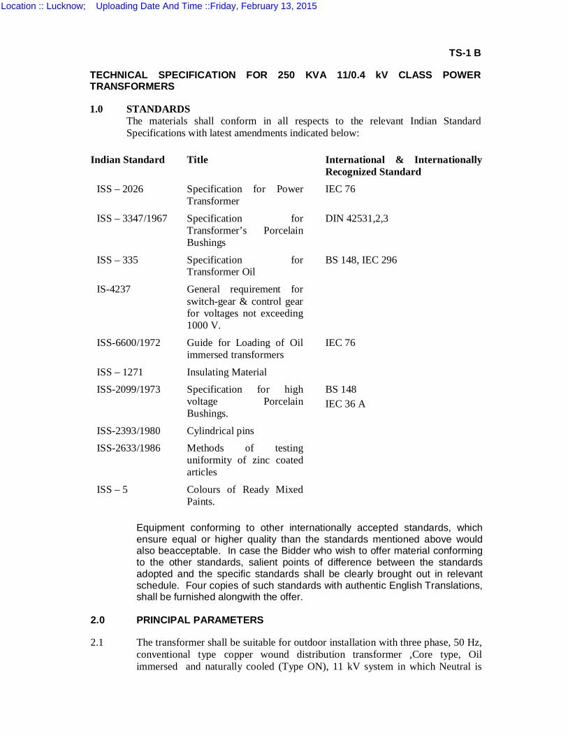
TS-1 B
TECHNICAL SPECIFICATION FOR 250 KVA 11/0.4 kV CLASS POWER TRANSFORMERS
1.0 STANDARDS
The materials shall conform in all respects to the relevant Indian Standard Specifications with latest amendments indicated below:
Indian Standard Title International & Internationally
Recognized Standard ISS – 2026 Specification for Power
Transformer IEC 76
ISS – 3347/1967
Specification for Transformer’s Porcelain Bushings
DIN 42531,2,3
ISS – 335 Specification for Transformer Oil
BS 148, IEC 296
IS-4237 General requirement for switch-gear & control gear for voltages not exceeding 1000 V.
ISS-6600/1972 Guide for Loading of Oil immersed transformers
IEC 76
ISS – 1271 Insulating Material ISS-2099/1973 Specification for high
voltage Porcelain Bushings.
BS 148 IEC 36 A
ISS-2393/1980 Cylindrical pins ISS-2633/1986 Methods of testing
uniformity of zinc coated articles
ISS – 5 Colours of Ready Mixed Paints.
Equipment conforming to other internationally accepted standards, which ensure equal or higher quality than the standards mentioned above would also beacceptable. In case the Bidder who wish to offer material conforming to the other standards, salient points of difference between the standards adopted and the specific standards shall be clearly brought out in relevant schedule. Four copies of such standards with authentic English Translations, shall be furnished alongwith the offer.
2.0 PRINCIPAL PARAMETERS
2.1 The transformer shall be suitable for outdoor installation with three phase, 50 Hz, conventional type copper wound distribution transformer ,Core type, Oil immersed and naturally cooled (Type ON), 11 kV system in which Neutral is
Location :: Lucknow; Uploading Date And Time ::Friday, February 13, 2015
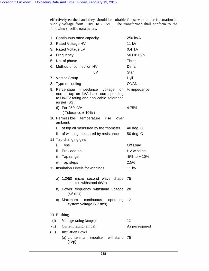
288
effectively earthed and they should be suitable for service under fluctuation in supply voltage from +10% to - 15%. The transformer shall conform to the following specific parameters.
1. Continuous rated capacity 250 kVA 2. Rated Voltage HV 11 kV 3. Rated Voltage LV 0.4 kV 4. Frequency 50 Hz ±5% 5. No. of phase Three 6. Method of connection HV Delta LV Star 7. Vector Group Dyll 8. Type of cooling ONAN 9. Percentage impedance voltage on
normal tap on kVA base corresponding to HV/LV rating and applicable tolerance as per ISS .
% impedance
(i) For 250 kVA ( Tolerance ± 10% )
4.75%
10. Permissible temperature rise over ambient.
i. of top oil measured by thermometer. 40 deg. C. ii. of winding measured by resistance 50 deg. C 11. Tap changing gear i. Type Off Load ii. Provided on HV winding iii. Tap range -5% to + 10% iv. Tap steps 2.5% 12. Insulation Levels for windings
11 kV
a) 1.2/50 micro second wave shape impulse withstand (kVp)
75
b) Power frequency withstand voltage (kV rms)
28
c) Maximum continuous operating system voltage (kV rms)
12
13. Bushings (i) Voltage rating (amps) 12 (ii) Current rating (amps) As per required (iii) Insulation Level (a) Lightening impulse withstand
(kVp) 75
Location :: Lucknow; Uploading Date And Time ::Friday, February 13, 2015
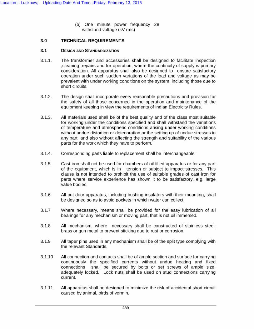
289
(b) One minute power frequency withstand voltage (kV rms)
28
3.0 TECHNICAL REQUIREMENTS
3.1 DESIGN AND STANDARDIZATION
3.1.1. The transformer and accessories shall be designed to facilitate inspection ,cleaning ,repairs and for operation, where the continuity of supply is primary consideration. All apparatus shall also be designed to ensure satisfactory operation under such sudden variations of the load and voltage as may be prevalent with under working conditions on the system, including those due to short circuits.
3.1.2. The design shall incorporate every reasonable precautions and provision for
the safety of all those concerned in the operation and maintenance of the equipment keeping in view the requirements of Indian Electricity Rules.
3.1.3. All materials used shall be of the best quality and of the class most suitable
for working under the conditions specified and shall withstand the variations of temperature and atmospheric conditions arising under working conditions without undue distortion or deterioration or the setting up of undue stresses in any part and also without affecting the strength and suitability of the various parts for the work which they have to perform.
3.1.4. Corresponding parts liable to replacement shall be interchangeable.
3.1.5. Cast iron shall not be used for chambers of oil filled apparatus or for any part
of the equipment, which is in tension or subject to impact stresses. This clause is not intended to prohibit the use of suitable grades of cast iron for parts where service experience has shown it to be satisfactory, e.g. large value bodies.
3.1.6 All out door apparatus, including bushing insulators with their mounting, shall
be designed so as to avoid pockets in which water can collect. 3.1.7 Where necessary, means shall be provided for the easy lubrication of all
bearings for any mechanism or moving part, that is not oil immersed. 3.1.8 All mechanism, where necessary shall be constructed of stainless steel,
brass or gun metal to prevent sticking due to rust or corrosion. 3.1.9 All taper pins used in any mechanism shall be of the split type complying with
the relevant Standards. 3.1.10 All connection and contacts shall be of ample section and surface for carrying
continuously the specified currents without undue heating and fixed connections shall be secured by bolts or set screws of ample size, adequately locked. Lock nuts shall be used on stud connections carrying current.
3.1.11 All apparatus shall be designed to minimize the risk of accidental short circuit
caused by animal, birds of vermin.
Location :: Lucknow; Uploading Date And Time ::Friday, February 13, 2015
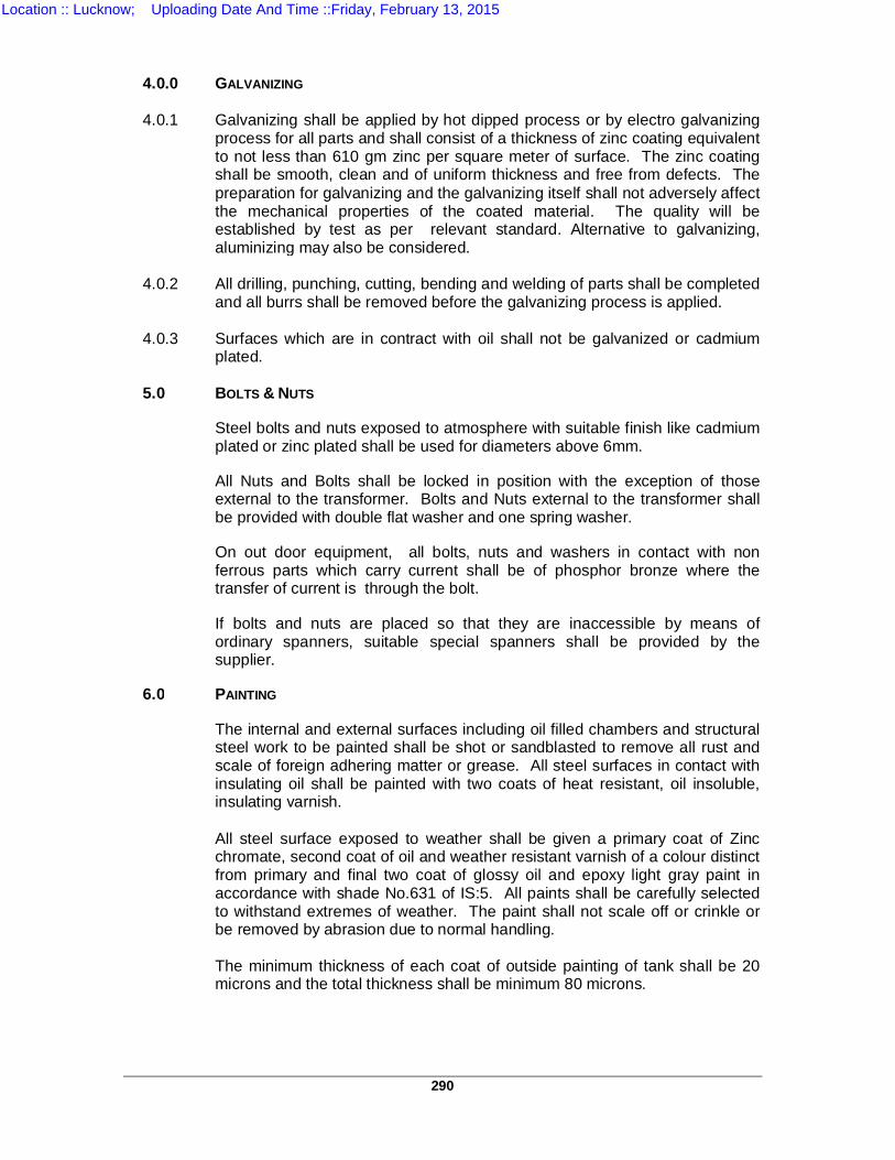
290
4.0.0 GALVANIZING 4.0.1 Galvanizing shall be applied by hot dipped process or by electro galvanizing
process for all parts and shall consist of a thickness of zinc coating equivalent to not less than 610 gm zinc per square meter of surface. The zinc coating shall be smooth, clean and of uniform thickness and free from defects. The preparation for galvanizing and the galvanizing itself shall not adversely affect the mechanical properties of the coated material. The quality will be established by test as per relevant standard. Alternative to galvanizing, aluminizing may also be considered.
4.0.2 All drilling, punching, cutting, bending and welding of parts shall be completed
and all burrs shall be removed before the galvanizing process is applied. 4.0.3 Surfaces which are in contract with oil shall not be galvanized or cadmium
plated. 5.0 BOLTS & NUTS
Steel bolts and nuts exposed to atmosphere with suitable finish like cadmium plated or zinc plated shall be used for diameters above 6mm.
All Nuts and Bolts shall be locked in position with the exception of those external to the transformer. Bolts and Nuts external to the transformer shall be provided with double flat washer and one spring washer.
On out door equipment, all bolts, nuts and washers in contact with non ferrous parts which carry current shall be of phosphor bronze where the transfer of current is through the bolt.
If bolts and nuts are placed so that they are inaccessible by means of ordinary spanners, suitable special spanners shall be provided by the supplier.
6.0 PAINTING
The internal and external surfaces including oil filled chambers and structural steel work to be painted shall be shot or sandblasted to remove all rust and scale of foreign adhering matter or grease. All steel surfaces in contact with insulating oil shall be painted with two coats of heat resistant, oil insoluble, insulating varnish.
All steel surface exposed to weather shall be given a primary coat of Zinc
chromate, second coat of oil and weather resistant varnish of a colour distinct from primary and final two coat of glossy oil and epoxy light gray paint in accordance with shade No.631 of IS:5. All paints shall be carefully selected to withstand extremes of weather. The paint shall not scale off or crinkle or be removed by abrasion due to normal handling.
The minimum thickness of each coat of outside painting of tank shall be 20
microns and the total thickness shall be minimum 80 microns.
Location :: Lucknow; Uploading Date And Time ::Friday, February 13, 2015
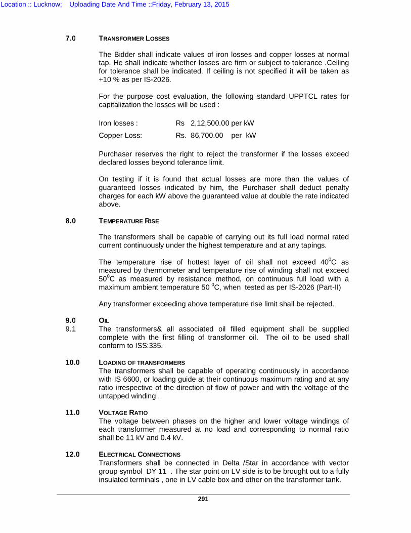
291
7.0 TRANSFORMER LOSSES
The Bidder shall indicate values of iron losses and copper losses at normal tap. He shall indicate whether losses are firm or subject to tolerance .Ceiling for tolerance shall be indicated. If ceiling is not specified it will be taken as +10 % as per IS-2026.
For the purpose cost evaluation, the following standard UPPTCL rates for
capitalization the losses will be used : Iron losses : Rs 2,12,500.00 per kW Copper Loss: Rs. 86,700.00 per kW Purchaser reserves the right to reject the transformer if the losses exceed
declared losses beyond tolerance limit. On testing if it is found that actual losses are more than the values of
guaranteed losses indicated by him, the Purchaser shall deduct penalty charges for each kW above the guaranteed value at double the rate indicated above.
8.0 TEMPERATURE RISE
The transformers shall be capable of carrying out its full load normal rated current continuously under the highest temperature and at any tapings.
The temperature rise of hottest layer of oil shall not exceed 400C as
measured by thermometer and temperature rise of winding shall not exceed 500C as measured by resistance method, on continuous full load with a maximum ambient temperature 50 0C, when tested as per IS-2026 (Part-II)
Any transformer exceeding above temperature rise limit shall be rejected. 9.0 OIL 9.1 The transformers& all associated oil filled equipment shall be supplied
complete with the first filling of transformer oil. The oil to be used shall conform to ISS:335.
10.0 LOADING OF TRANSFORMERS The transformers shall be capable of operating continuously in accordance
with IS 6600, or loading guide at their continuous maximum rating and at any ratio irrespective of the direction of flow of power and with the voltage of the untapped winding .
11.0 VOLTAGE RATIO The voltage between phases on the higher and lower voltage windings of
each transformer measured at no load and corresponding to normal ratio shall be 11 kV and 0.4 kV.
12.0 ELECTRICAL CONNECTIONS Transformers shall be connected in Delta /Star in accordance with vector
group symbol DY 11 . The star point on LV side is to be brought out to a fully insulated terminals , one in LV cable box and other on the transformer tank.
Location :: Lucknow; Uploading Date And Time ::Friday, February 13, 2015
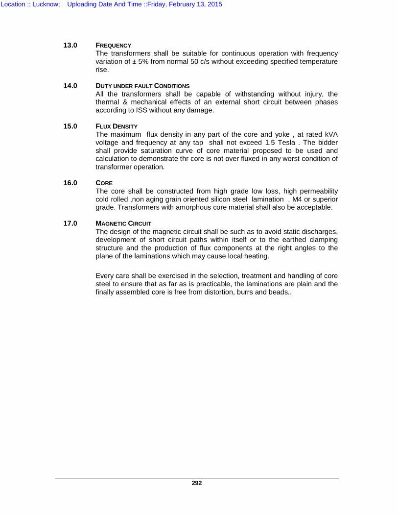
292
13.0 FREQUENCY The transformers shall be suitable for continuous operation with frequency
variation of ± 5% from normal 50 c/s without exceeding specified temperature rise.
14.0 DUTY UNDER FAULT CONDITIONS All the transformers shall be capable of withstanding without injury, the
thermal & mechanical effects of an external short circuit between phases according to ISS without any damage.
15.0 FLUX DENSITY The maximum flux density in any part of the core and yoke , at rated kVA
voltage and frequency at any tap shall not exceed 1.5 Tesla . The bidder shall provide saturation curve of core material proposed to be used and calculation to demonstrate thr core is not over fluxed in any worst condition of transformer operation.
16.0 CORE The core shall be constructed from high grade low loss, high permeability
cold rolled ,non aging grain oriented silicon steel lamination , M4 or superior grade. Transformers with amorphous core material shall also be acceptable.
17.0 MAGNETIC CIRCUIT The design of the magnetic circuit shall be such as to avoid static discharges,
development of short circuit paths within itself or to the earthed clamping structure and the production of flux components at the right angles to the plane of the laminations which may cause local heating.
Every care shall be exercised in the selection, treatment and handling of core
steel to ensure that as far as is practicable, the laminations are plain and the finally assembled core is free from distortion, burrs and beads..
Location :: Lucknow; Uploading Date And Time ::Friday, February 13, 2015
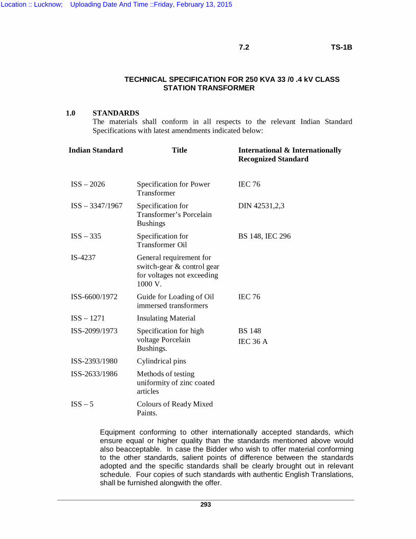
293
7.2 TS-1B
TECHNICAL SPECIFICATION FOR 250 KVA 33 /0 .4 kV CLASS STATION TRANSFORMER
1.0 STANDARDS
The materials shall conform in all respects to the relevant Indian Standard Specifications with latest amendments indicated below:
Indian Standard Title International & Internationally
Recognized Standard ISS – 2026 Specification for Power
Transformer IEC 76
ISS – 3347/1967
Specification for Transformer’s Porcelain Bushings
DIN 42531,2,3
ISS – 335 Specification for Transformer Oil
BS 148, IEC 296
IS-4237 General requirement for switch-gear & control gear for voltages not exceeding 1000 V.
ISS-6600/1972 Guide for Loading of Oil immersed transformers
IEC 76
ISS – 1271 Insulating Material
ISS-2099/1973 Specification for high voltage Porcelain Bushings.
BS 148 IEC 36 A
ISS-2393/1980 Cylindrical pins
ISS-2633/1986 Methods of testing uniformity of zinc coated articles
ISS – 5 Colours of Ready Mixed Paints.
Equipment conforming to other internationally accepted standards, which ensure equal or higher quality than the standards mentioned above would also beacceptable. In case the Bidder who wish to offer material conforming to the other standards, salient points of difference between the standards adopted and the specific standards shall be clearly brought out in relevant schedule. Four copies of such standards with authentic English Translations, shall be furnished alongwith the offer.
Location :: Lucknow; Uploading Date And Time ::Friday, February 13, 2015
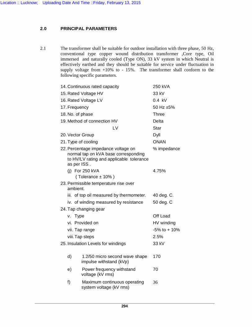
294
2.0 PRINCIPAL PARAMETERS
2.1 The transformer shall be suitable for outdoor installation with three phase, 50 Hz, conventional type copper wound distribution transformer ,Core type, Oil immersed and naturally cooled (Type ON), 33 kV system in which Neutral is effectively earthed and they should be suitable for service under fluctuation in supply voltage from +10% to - 15%. The transformer shall conform to the following specific parameters.
14. Continuous rated capacity 250 kVA 15. Rated Voltage HV 33 kV 16. Rated Voltage LV 0.4 kV 17. Frequency 50 Hz ±5% 18. No. of phase Three 19. Method of connection HV Delta LV Star 20. Vector Group Dyll 21. Type of cooling ONAN 22. Percentage impedance voltage on
normal tap on kVA base corresponding to HV/LV rating and applicable tolerance as per ISS .
% impedance
(j) For 250 kVA ( Tolerance ± 10% )
4.75%
23. Permissible temperature rise over ambient.
iii. of top oil measured by thermometer. 40 deg. C. iv. of winding measured by resistance 50 deg. C 24. Tap changing gear v. Type Off Load vi. Provided on HV winding vii. Tap range -5% to + 10% viii. Tap steps 2.5% 25. Insulation Levels for windings
33 kV
d) 1.2/50 micro second wave shape impulse withstand (kVp)
170
e) Power frequency withstand voltage (kV rms)
70
f) Maximum continuous operating system voltage (kV rms)
36
Location :: Lucknow; Uploading Date And Time ::Friday, February 13, 2015
295
26. Bushings (iv) Voltage rating (amps) 36 (v) Current rating (amps) As per required (vi) Insulation Level (c) Lightening impulse withstand
(kVp) 170
(d) One minute power frequency withstand voltage (kV rms)
70
3.0 TECHNICAL REQUIREMENTS
3.1 DESIGN AND STANDARDIZATION
3.1.6. The transformer and accessories shall be designed to facilitate inspection
,cleaning ,repairs and for operation, where the continuity of supply is primary consideration. All apparatus shall also be designed to ensure satisfactory operation under such sudden variations of the load and voltage as may be prevalent with under working conditions on the system, including those due to short circuits.
3.1.7. The design shall incorporate every reasonable precautions and provision for
the safety of all those concerned in the operation and maintenance of the equipment keeping in view the requirements of Indian Electricity Rules.
3.1.8. All materials used shall be of the best quality and of the class most suitable
for working under the conditions specified and shall withstand the variations of temperature and atmospheric conditions arising under working conditions without undue distortion or deterioration or the setting up of undue stresses in any part and also without affecting the strength and suitability of the various parts for the work which they have to perform.
3.1.9. Corresponding parts liable to replacement shall be interchangeable.
3.1.10. Cast iron shall not be used for chambers of oil filled apparatus or for any part
of the equipment, which is in tension or subject to impact stresses. This clause is not intended to prohibit the use of suitable grades of cast iron for parts where service experience has shown it to be satisfactory, e.g. large value bodies.
3.1.12 All out door apparatus, including bushing insulators with their mounting, shall
be designed so as to avoid pockets in which water can collect. 3.1.13 Where necessary, means shall be provided for the easy lubrication of all
bearings for any mechanism or moving part, that is not oil immersed. 3.1.14 All mechanism, where necessary shall be constructed of stainless steel,
brass or gun metal to prevent sticking due to rust or corrosion. 3.1.15 All taper pins used in any mechanism shall be of the split type complying with
the relevant Standards.
Location :: Lucknow; Uploading Date And Time ::Friday, February 13, 2015
296
3.1.16 All connection and contacts shall be of ample section and surface for carrying
continuously the specified currents without undue heating and fixed connections shall be secured by bolts or set screws of ample size, adequately locked. Lock nuts shall be used on stud connections carrying current.
3.1.17 All apparatus shall be designed to minimize the risk of accidental short circuit
caused by animal, birds of vermin. 4.0.4 GALVANIZING 4.0.5 Galvanizing shall be applied by hot dipped process or by electro galvanizing
process for all parts and shall consist of a thickness of zinc coating equivalent to not less than 610 gm zinc per square meter of surface. The zinc coating shall be smooth, clean and of uniform thickness and free from defects. The preparation for galvanizing and the galvanizing itself shall not adversely affect the mechanical properties of the coated material. The quality will be established by test as per relevant standard. Alternative to galvanizing, aluminizing may also be considered.
4.0.6 All drilling, punching, cutting, bending and welding of parts shall be completed
and all burrs shall be removed before the galvanizing process is applied. 4.0.7 Surfaces which are in contract with oil shall not be galvanized or cadmium
plated. 6.0 BOLTS & NUTS
Steel bolts and nuts exposed to atmosphere with suitable finish like cadmium plated or zinc plated shall be used for diameters above 6mm.
All Nuts and Bolts shall be locked in position with the exception of those external to the transformer. Bolts and Nuts external to the transformer shall be provided with double flat washer and one spring washer.
On out door equipment, all bolts, nuts and washers in contact with non ferrous parts which carry current shall be of phosphor bronze where the transfer of current is through the bolt.
If bolts and nuts are placed so that they are inaccessible by means of ordinary spanners, suitable special spanners shall be provided by the supplier.
Location :: Lucknow; Uploading Date And Time ::Friday, February 13, 2015
297
6.0 PAINTING
The internal and external surfaces including oil filled chambers and structural
steel work to be painted shall be shot or sandblasted to remove all rust and scale of foreign adhering matter or grease. All steel surfaces in contact with insulating oil shall be painted with two coats of heat resistant, oil insoluble, insulating varnish.
All steel surface exposed to weather shall be given a primary coat of Zinc
chromate, second coat of oil and weather resistant varnish of a colour distinct from primary and final two coat of glossy oil and epoxy light gray paint in accordance with shade No.631 of IS:5. All paints shall be carefully selected to withstand extremes of weather. The paint shall not scale off or crinkle or be removed by abrasion due to normal handling.
The minimum thickness of each coat of outside painting of tank shall be 20
microns and the total thickness shall be minimum 80 microns.
7.0 TRANSFORMER LOSSES
The Bidder shall indicate values of iron losses and copper losses at normal
tap. He shall indicate whether losses are firm or subject to tolerance .Ceiling for tolerance shall be indicated. If ceiling is not specified it will be taken as +10 % as per IS-2026.
For the purpose cost evaluation, the following standard UPPTCL rates for
capitalization the losses will be used : Iron losses : Rs 2,12,500.00 per kW Copper Loss: Rs. 86,700.00 per kW Purchaser reserves the right to reject the transformer if the losses exceed
declared losses beyond tolerance limit. On testing if it is found that actual losses are more than the values of
guaranteed losses indicated by him, the Purchaser shall deduct penalty charges for each kW above the guaranteed value at double the rate indicated above.
8.0 TEMPERATURE RISE
The transformers shall be capable of carrying out its full load normal rated current continuously under the highest temperature and at any tapings.
The temperature rise of hottest layer of oil shall not exceed 400C as
measured by thermometer and temperature rise of winding shall not exceed 500C as measured by resistance method, on continuous full load with a maximum ambient temperature 50 0C, when tested as per IS-2026 (Part-II)
Any transformer exceeding above temperature rise limit shall be rejected.
Location :: Lucknow; Uploading Date And Time ::Friday, February 13, 2015
298
9.0 OIL
9.1 The transformers& all associated oil filled equipment shall be supplied complete with the first filling of transformer oil. The oil to be used shall conform to ISS:335.
10.0 LOADING OF TRANSFORMERS
The transformers shall be capable of operating continuously in accordance with IS 6600, or loading guide at their continuous maximum rating and at any ratio irrespective of the direction of flow of power and with the voltage of the untapped winding .
11.0 VOLTAGE RATIO
The voltage between phases on the higher and lower voltage windings of
each transformer measured at no load and corresponding to normal ratio shall be 33 kV and 0.4 kV.
12.0 ELECTRICAL CONNECTIONS Transformers shall be connected in Delta /Star in accordance with vector
group symbol DY 11 . The star point on LV side is to be brought out to a fully insulated terminals , one in LV cable box and other on the transformer tank.
13.0 FREQUENCY The transformers shall be suitable for continuous operation with frequency
variation of ± 5% from normal 50 c/s without exceeding specified temperature rise.
14.0 DUTY UNDER FAULT CONDITIONS
All the transformers shall be capable of withstanding without injury, the
thermal & mechanical effects of an external short circuit between phases according to ISS without any damage.
15.0 FLUX DENSITY
The maximum flux density in any part of the core and yoke , at rated kVA
voltage and frequency at any tap shall not exceed 1.5 Tesla . The bidder shall provide saturation curve of core material proposed to be used and calculation to demonstrate thr core is not over fluxed in any worst condition of transformer operation.
16.0 CORE
The core shall be constructed from high grade low loss, high permeability
cold rolled ,non aging grain oriented silicon steel lamination , M4 or superior grade. Transformers with amorphous core material shall also be acceptable.
Location :: Lucknow; Uploading Date And Time ::Friday, February 13, 2015
299
17.0 MAGNETIC CIRCUIT The design of the magnetic circuit shall be such as to avoid static discharges,
development of short circuit paths within itself or to the earthed clamping structure and the production of flux components at the right angles to the plane of the laminations which may cause local heating.
Every care shall be exercised in the selection, treatment and handling of core
steel to ensure that as far as is practicable, the laminations are plain and the finally assembled core is free from distortion, burrs and beads..
Every lamination shall be insulated so as it will not deteriorate due to
mechanical pressure and the action of hot transformer oil. Oil ducts shall be provided where necessary to ensure adequate cooling.
The winding structure and major insulation shall not obstruct the free flow of oil through such ducts. Where the magnetic circuit is divided into pockets by cooling. Ducts parallel to the plane of the laminations or by insulation material above 0.25 mm thick, tinned copper strip bridging pieces shall be inserted to maintain electrical continuity between pockets.
The framework and clamping arrangements shall be earthed. The class and type of in insulation used on the core bolts and under the nuts
and side places shall be stated in ordering schedule. 18.0 SUPPRESSION OF HARMONICS The transformers shall be designed with particular attention to the
suppression of harmonic voltages, especially the third and fifth. So as to eliminate wave from distortion and any possibility of high frequency disturbances, inductive effect or of circulating currents between the neutral points at different transforming stations reaching such a magnitude as to cause interference with communication circuits. For achieving this, delta connected stabilizing winding should be avoided.
19.0 VIBRATION AND NOISE Every care shall be taken to ensure that the design and manufacture of all
transformers and auxiliary plant shall be such as to reduce noise and vibration to the level of that obtained in good modern practice.
20.0 MECHANICAL CONSTRUCTION OF CORES 1. All parts of the cores shall be of robust design capable of withstanding
any shocks to which they may be subjected during lifting, transport, installation and service. The bolts used in assembly or core shall be suitably insulated and clamping structure shall be so constructed that the eddy currents are minimum.
2. All structural members of the assembled cores shall be of steel. All
casting shall be settled and structural steel adequately cleaned and painted before being built into the structure. Any non magnetic or high resistance alloy used shall be of established quality.
Location :: Lucknow; Uploading Date And Time ::Friday, February 13, 2015
300
3. Adequate fitments shall be provided to enable the core and windings
to be lifted. 4. Suitable provision shall be made for the storage of any removable
portions of the lifting lugs on the transformer tank. 5. Adequate provision shall be made to prevent movement of the core
and winding relative to the tank during transport and installation or while in service. Core clamping bolts shall be effectively insulated with craft paper and fiberglass tubes.
6. The supporting frame work of the cores shall be designed as to avoid
the presence of pockets which would prevent complete emptying of the tank through the drain valve or cause trapping of air during filling.
21.0 WINDINGS
i) The windings shall be so designed to reduce to a minimum out of
balance forces in the transformer at all voltages ratios.
ii) The windings shall also be designed such that all coil assemblies of identical voltage rating shall be interchangeable and repairing of the winding can be made readily without special equipments.
iii) The conductors used in the coils shall be best suited to the requirements and all permanent current carrying joints in the winding and leads shall be welded or brazed.
iv) The insulation of transformer windings and connections shall be free
from insulating compositions liable to soften, ooze out, shrink or collapse during service.
v) No strip conductor shall have a width exceeding six times its
thickness. vi) The winding shall be compact and symmetrical about the centre line of
core and shall be framed on suitable synthetic resin bonded paper sheets type I, Conforming to the relevant standards.
vii) Kraft paper used for inter layer insulation of H.V. shall be of uniform
density and thickness free from pin holes and free from any foreign particles. The Kraft paper shall have a minimum thickness of 4 mils. The end turns of each layer shall be properly and fully covered to avoid inter layer flashover. The kraft paper used for this purpose shall be in conformity with relevant standard (paper for Electrical purpose). Ordinary paper or Bamboo paper should not be used in any case. The insulation of coils shall be treated with suitable insulating varnish or equivalent compound or impregnated in transformer oil to develop the full Electrical Strength in the windings. All the materials used in the insulation and assembly of the windings shall be insoluble, non catalytic and chemically inactive in the hot transformer oil and shall not soften or otherwise be adversely affected under the operating condition.
Location :: Lucknow; Uploading Date And Time ::Friday, February 13, 2015

301
viii) Inter phase vertical barriers of proper insulating paper of adequate
thickness should be provided in order to avoid inter phase flashovers. These barriers should be suitably fastened & supported to avoid their lateral movement. Wherever necessary barriers of insulating paper of adequate thickness should also be provided in order to avoid phase to earth flash over.
ix) All threaded connections shall be provided with locking facilities. All
leads from the winding to the terminal board and bushing shall be rigidly supported to prevent injury from vibration.
x) Proper number of oil ducts and spacers should be provided between
the sections of H.V. limbs for proper circulation of the insulating oil and to reduce hot spots on the winding.
xi) The number of sections on each HV limb shall be minimum four. 22.0 TANK The transformer tank and cover shall be fabricated from good commercial
grade low carbon steel suitable for welding and of adequate thickness. The tank and the cover shall be welded construction. All seems shall be welded and where practicable shall be double welded. The tank shall have sufficient strength to withstand without permanent distortion (I) filling by vacuum (II) continuous internal gas pressure of 0.7 Atm with oil at operating level. The tank cover shall be bolted to the tank and the transformer design shall be such that the tank will not be split between the lower and upper cooler connection for untanking.
All bolted connections to the tank shall be fitted with suitable oil tight synthetic
rubber and cork composition gaskets, which shall give satisfactory service under the operating conditions. Special attention shall be given to the methods of making the hot oil tight joints between the tank and cover as also the between the cover, the bushings and all other out lets to ensure that the joints can be remade satisfactorily and with case, with the help of semiskilled labour. Where compressible gaskets are used, steps shall be provided to prevent over compression.
Suitable guides shall be provided for positioning various parts during
assembly or dismantling. Adequate space shall be provided between the cores and windings and the bottom of the tank for collection for any sediment. Lifting eyes or lugs shall be provided on all parts of transformers requiring independent handling during assembly or dismantling. In addition, the transformer tanks shall be provided with lifting lugs and basses properly secured to the side of the tank for lifting the transformer either by crane or by jacks. The design of the tank, the lifting lugs and bosses shall be such that the complete transformer assembly filled with oil can be lifted with the use of these lugs without any damage or distortions.
The tank shall be provided with 2 suitable copper alloy pads for the purpose of grounding suitably for 50 x 6 mm G.I strip. The G.I earthing strip shall be clamped without drilling any hole into it, between two surfaces of the pads. Each tank shall be equipped with the following values with flanges for external connection.
Location :: Lucknow; Uploading Date And Time ::Friday, February 13, 2015
302
i) One drain cum lower filter valve fitted on the transformer and placed to
completely drain the tank. This valve shall be equipped with a small sampling cock.
ii) One filter valve shall be located at the top of the tank on the side
opposite to this lower value. The opening of this valve shall be baffled to prevents deration of the oil.
23.0 UNDER CARRIAGE The transformer tank shall be support on a structural steel base equipped
with cast iron flat wheels suitable for moving the transformer complete (with oil)
The gauge of wheels shall be 1000 mm. Pulling eyes shall be provided to facilitate moving of the transformer and they
shall be suitably dragged in a vertical direction so that bending does not occur when the pull has vertical component.
24.0 TAP CHANGING MECHANISM
The transformers shall be provided with off-circuit tap selector switch on HV
windings for HV variation from – 5% to (+) 10% in steps of 2.5% to give a constant L.V.
These steps shall be controlled by hand and provisions shall be made for
indication of tap position and locking on any particular tap. 25.0 All metal parts of the transformer with the exception of the individual core
laminations, core bolts and associated clamping plates shall be maintained at some fixed potential and core should be earthed at points.
26.0 COOLING METHOD Transformers shall have ‘ONAN’ cooling only. 27.0 PARALLEL OPERATION The transformers shall operate satisfactorily in parallel among them selves
when connected across the same H.V. and L.V. Bus Bars. 28.0 H.V. TERMINAL ARRANGEMENT The H.V. terminals shall be brought into separate weather proof solid
porcelain bushing conforming to IS-2099, IS-8605 and IS-3347 with suitable arcing horns.
The inner ends of the bushing shall be completely immersed in the oil. The H.V. bushings rods should be locked in position so that twisting of the H.T. leads is avoided during tightening of nuts of bushing rods.
Location :: Lucknow; Uploading Date And Time ::Friday, February 13, 2015
303
L.V. TERMINAL ARRANGEMENT The L.V. terminals shall be brought out on bushings provided inside the cable
box suitable for 4 x 1C – 400 sq. mm per phase as well as neutral for, P.V.C armoured cables. The neutral of the L.V. side shall be brought out on a bushing inside the cable box. In addition
to above, another neutral bushing shall also be provided on the transformer
tank for separate earthing. The size of the cable box and position of glands should be such that it is
convenient to carry out cabling work i.e. to make connections, etc. and fixing of cable box covering and to attend operation and maintenance. The dimensions of cable box and position of glands should be shown clearly in the outline drawing of the transformer. All the L.V., as well as neutral bushing shall be interchangeable.
29.0 FITTINGS & ACCESSORIES i) Conservator tank having inter connections pipe, projecting 20 mm.
above bottom of conservator to erect sump for collections of impurity, between conservator and main tank, 30 mm, dia drain value, oil fillings hole with cap on the top of the conservator.
ii) Shut off value in inter connecting pipe between conservator and main tank.
iii) Two nos. earthing terminals suitable for 50 x 6 mm G.I. strip.
7.3.1.1.1.1.1.1iv) Oil level gauge with toughened glass with minimum marking.
v) Lifting lugs for core inside the transformers.
vi) Lifting lugs for complete transformers vii) Thermometer pocket in accordance to IS:3639. viii) Dehydrating breather. ix) Air release plug on the transformer tank to release trapped air inside
the tank when filling oil through conservator. x) One drain cum sampling value having narrow orifice with locking
arrangement on the bottom of tank.
xi) One filter valve on the Upper top side of the tank. xii) Lifting lugs for tank cover. xiii) Inspection hole. xiv) 4” dia dial type thermometer for oil temp. with max. pointer and set of
contact for alarm. xv) One winding temp. indicator with max. pointer and two sets of contacts
for alarm and trip purpose. xvi) Explosion vent with diaphragm. xvii) Anodised aluminum non-detachable engraved rating and diagram
plate containing reference of purchase order and “Property of U.P. Power Transmission Corporation Ltd ” apart from the essential details as per IS:2026/1977. No load/load losses must also be engraved on the diagram plate.
Location :: Lucknow; Uploading Date And Time ::Friday, February 13, 2015
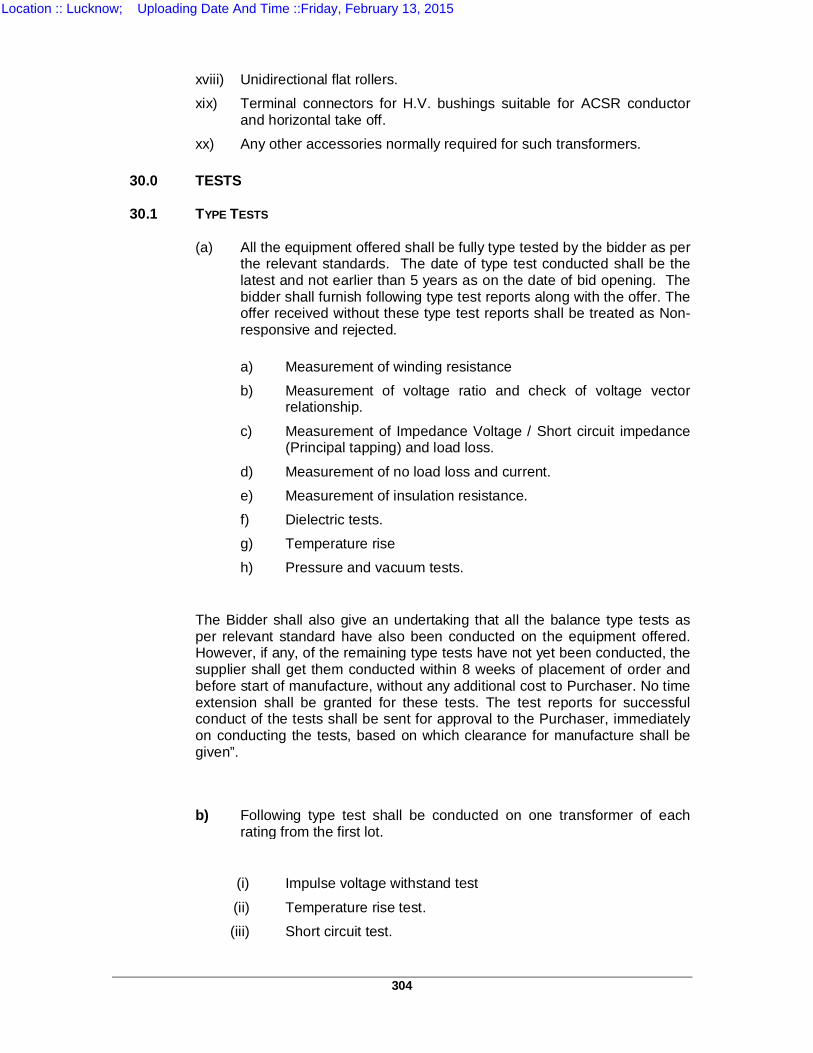
304
xviii) Unidirectional flat rollers. xix) Terminal connectors for H.V. bushings suitable for ACSR conductor
and horizontal take off. xx) Any other accessories normally required for such transformers. 30.0 TESTS 30.1 TYPE TESTS (a) All the equipment offered shall be fully type tested by the bidder as per
the relevant standards. The date of type test conducted shall be the latest and not earlier than 5 years as on the date of bid opening. The bidder shall furnish following type test reports along with the offer. The offer received without these type test reports shall be treated as Non-responsive and rejected.
a) Measurement of winding resistance b) Measurement of voltage ratio and check of voltage vector
relationship.
c) Measurement of Impedance Voltage / Short circuit impedance (Principal tapping) and load loss.
d) Measurement of no load loss and current. e) Measurement of insulation resistance. f) Dielectric tests. g) Temperature rise h) Pressure and vacuum tests.
The Bidder shall also give an undertaking that all the balance type tests as per relevant standard have also been conducted on the equipment offered. However, if any, of the remaining type tests have not yet been conducted, the supplier shall get them conducted within 8 weeks of placement of order and before start of manufacture, without any additional cost to Purchaser. No time extension shall be granted for these tests. The test reports for successful conduct of the tests shall be sent for approval to the Purchaser, immediately on conducting the tests, based on which clearance for manufacture shall be given”.
b) Following type test shall be conducted on one transformer of each rating from the first lot.
(i) Impulse voltage withstand test
(ii) Temperature rise test. (iii) Short circuit test.
Location :: Lucknow; Uploading Date And Time ::Friday, February 13, 2015
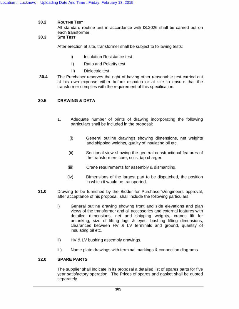
305
30.2 ROUTINE TEST All standard routine test in accordance with IS:2026 shall be carried out on
each transformer. 30.3 SITE TEST
After erection at site, transformer shall be subject to following tests:
i) Insulation Resistance test ii) Ratio and Polarity test iii) Dielectric test 30.4
The Purchaser reserves the right of having other reasonable test carried out at his own expense either before dispatch or at site to ensure that the transformer complies with the requirement of this specification.
30.5 DRAWING & DATA
1. Adequate number of prints of drawing incorporating the following particulars shall be included in the proposal:
(i) General outline drawings showing dimensions, net weights and shipping weights, quality of insulating oil etc.
(ii) Sectional view showing the general constructional features of
the transformers core, coils, tap charger. (iii) Crane requirements for assembly & dismantling. (iv) Dimensions of the largest part to be dispatched, the position
in which it would be transported. 31.0 Drawing to be furnished by the Bidder for Purchaser’s/engineers approval,
after acceptance of his proposal, shall include the following particulars.
i) General outline drawing showing front and side elevations and plan views of the transformer and all accessories and external features with detailed dimensions, net and shipping weights, cranes lift for untanking, size of lifting lugs & eyes, bushing lifting dimensions, clearances between HV & LV terminals and ground, quantity of insulating oil etc.
ii) HV & LV bushing assembly drawings. iii) Name plate drawings with terminal markings & connection diagrams. 32.0 SPARE PARTS The supplier shall indicate in its proposal a detailed list of spares parts for five
year satisfactory operation. The Prices of spares and gasket shall be quoted separately
Location :: Lucknow; Uploading Date And Time ::Friday, February 13, 2015
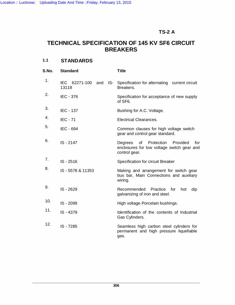
306
TS-2 A
TECHNICAL SPECIFICATION OF 145 KV SF6 CIRCUIT BREAKERS
1.1 STANDARDS S.No. Standard Title
1. IEC 62271-100 and IS-
13118 Specification for alternating current circuit Breakers.
2. IEC - 376 Specification for acceptance of new supply of SF6.
3. IEC - 137 Bushing for A.C. Voltage. 4. IEC - 71 Electrical Clearances. 5. IEC - 694 Common clauses for high voltage switch
gear and control gear standard. 6. IS - 2147 Degrees of Protection Provided for
enclosures for low voltage switch gear and control gear.
7. IS - 2516 Specification for circuit Breaker 8. IS - 5578 & 11353 Making and arrangement for switch gear
bus bar, Main Connections and auxiliary wiring.
9. IS - 2629 Recommended Practice for hot dip galvanizing of iron and steel.
10. IS - 2099 High voltage Porcelain bushings. 11. IS - 4379 Identification of the contents of Industrial
Gas Cylinders. 12. IS - 7285 Seamless high carbon steel cylinders for
permanent and high pressure liquefiable gas.
Location :: Lucknow; Uploading Date And Time ::Friday, February 13, 2015
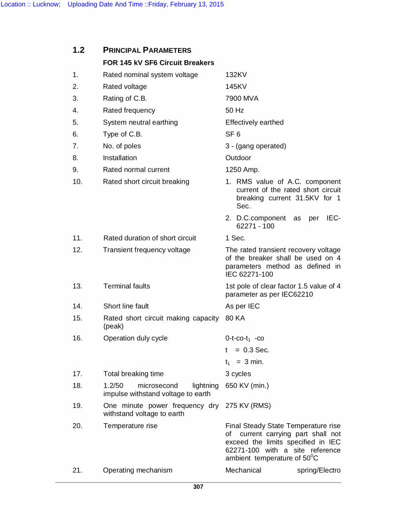
307
1.2
PRINCIPAL PARAMETERS
FOR 145 kV SF6 Circuit Breakers 1. Rated nominal system voltage 132KV 2. Rated voltage 145KV 3. Rating of C.B. 7900 MVA
4. Rated frequency 50 Hz
5. System neutral earthing Effectively earthed 6. Type of C.B. SF 6 7. No. of poles 3 - (gang operated) 8. Installation Outdoor 9. Rated normal current 1250 Amp.
10. Rated short circuit breaking 1. RMS value of A.C. component current of the rated short circuit breaking current 31.5KV for 1 Sec.
2. D.C.component as per IEC-62271 - 100
11. Rated duration of short circuit 1 Sec. 12.
Transient frequency voltage The rated transient recovery voltage of the breaker shall be used on 4 parameters method as defined in IEC 62271-100
13. Terminal faults 1st pole of clear factor 1.5 value of 4 parameter as per IEC62210
14. Short line fault As per IEC
15. Rated short circuit making capacity (peak)
80 KA
16. Operation duly cycle 0-t-co-t1 -co t = 0.3 Sec. t1 = 3 min.
17. Total breaking time 3 cycles 18. 1.2/50 microsecond lightning
impulse withstand voltage to earth 650 KV (min.)
19. One minute power frequency dry withstand voltage to earth
275 KV (RMS)
20. Temperature rise Final Steady State Temperature rise of current carrying part shall not exceed the limits specified in IEC 62271-100 with a site reference ambient temperature of 500C
21. Operating mechanism Mechanical spring/Electro
Location :: Lucknow; Uploading Date And Time ::Friday, February 13, 2015
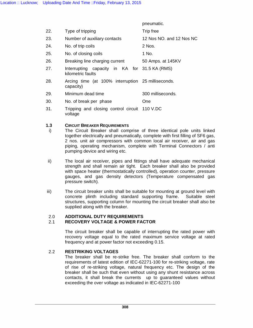
308
pneumatic.
22. Type of tripping Trip free 23. Number of auxiliary contacts 12 Nos NO. and 12 Nos NC 24. No. of trip coils 2 Nos.
25. No. of closing coils 1 No. 26. Breaking line charging current 50 Amps. at 145KV 27. Interrupting capacity in KA for
kilometric faults 31.5 KA (RMS)
28. Arcing time (at 100% interruption capacity)
25 milliseconds.
29. Minimum dead time 300 milliseconds.
30. No. of break per phase One 31. Tripping and closing control circuit
voltage 110 V.DC
1.3 CIRCUIT BREAKER REQUIREMENTS
i) The Circuit Breaker shall comprise of three identical pole units linked together electrically and pneumatically, complete with first filling of SF6 gas, 2 nos. unit air compressors with common local air receiver, air and gas piping, operating mechanism, complete with Terminal Connectors / anti pumping device and wiring etc.
ii) The local air receiver, pipes and fittings shall have adequate mechanical strength and shall remain air tight. Each breaker shall also be provided with space heater (thermostatically controlled), operation counter, pressure gauges, and gas density detectors (Temperature compensated gas pressure switch).
iii) The circuit breaker units shall be suitable for mounting at ground level with concrete plinth including standard supporting frame. Suitable steel structures, supporting column for mounting the circuit breaker shall also be supplied along with the breaker.
2.0 ADDITIONAL DUTY REQUIREMENTS 2.1 RECOVERY VOLTAGE & POWER FACTOR
The circuit breaker shall be capable of interrupting the rated power with recovery voltage equal to the rated maximum service voltage at rated frequency and at power factor not exceeding 0.15.
2.2 RESTRIKING VOLTAGES The breaker shall be re-strike free. The breaker shall conform to the
requirements of latest edition of IEC-62271-100 for re-striking voltage, rate of rise of re-striking voltage, natural frequency etc. The design of the breaker shall be such that even without using any shunt resistance across contacts, it shall break the currents up to guaranteed values without exceeding the over voltage as indicated in IEC-62271-100
Location :: Lucknow; Uploading Date And Time ::Friday, February 13, 2015
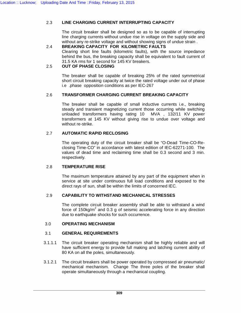
309
2.3 LINE CHARGING CURRENT INTERRUPTING CAPACITY
The circuit breaker shall be designed so as to be capable of interrupting line charging currents without undue rise in voltage on the supply side and without any re-strike voltage and without showing signs of undue strain .
2.4 BREAKING CAPACITY FOR KILOMETRIC FAULTS Clearing short line faults (kilometric faults), with the source impedance
behind the bus, the breaking capacity shall be equivalent to fault current of 31.5 KA rms for 1 second for 145 KV breakers.
2.5 OUT OF PHASE CLOSING
The breaker shall be capable of breaking 25% of the rated symmetrical short circuit breaking capacity at twice the rated voltage under out of phase i.e .phase opposition conditions as per IEC-267
2.6 TRANSFORMER CHARGING CURRENT BREAKING CAPACITY
The breaker shall be capable of small inductive currents i.e., breaking steady and transient magnetizing current those occurring while switching unloaded transformers having rating 10 MVA , 132/11 KV power transformers at 145 KV without giving rise to undue over voltage and without re-strike.
2.7 AUTOMATIC RAPID RECLOSING
The operating duty of the circuit breaker shall be “O-Dead Time-CO-Re-closing Time-CO” in accordance with latest edition of IEC-62271-100. The values of dead time and reclaiming time shall be 0.3 second and 3 min. respectively.
2.8 TEMPERATURE RISE
The maximum temperature attained by any part of the equipment when in service at site under continuous full load conditions and exposed to the direct rays of sun, shall be within the limits of concerned IEC.
2.9 CAPABILITY TO WITHSTAND MECHANICAL STRESSES
The complete circuit breaker assembly shall be able to withstand a wind force of 150kg/m2 and 0.3 g of seismic accelerating force in any direction due to earthquake shocks for such occurrence.
3.0 OPERATING MECHANISM
3.1 GENERAL REQUIREMENTS
3.1.1.1 The circuit breaker operating mechanism shall be highly reliable and will have sufficient energy to provide full making and latching current ability of 80 KA on all the poles, simultaneously.
3.1.2.1 The circuit breakers shall be power operated by compressed air pneumatic/ mechanical mechanism. Change The three poles of the breaker shall operate simultaneously through a mechanical coupling.
Location :: Lucknow; Uploading Date And Time ::Friday, February 13, 2015
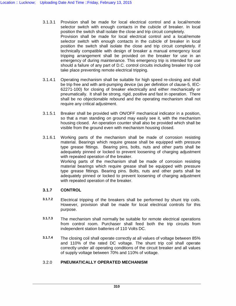
310
3.1.3.1 Provision shall be made for local electrical control and a local/remote
selector switch with enough contacts in the cubicle of breaker. In local position the switch shall isolate the close and trip circuit completely. Provision shall be made for local electrical control and a local/remote selector switch with enough contacts in the cubicle of breaker in local position the switch shall isolate the close and trip circuit completely. if technically compatible with design of breaker a manual emergency local tripping arrangement shall be provided on the breaker for use in an emergency of during maintenance. This emergency trip is intended for use should a failure of any part of D.C. control circuits including breaker trip coil take place preventing remote electrical tripping.
3.1.4.1 Operating mechanism shall be suitable for high speed re-closing and shall
be trip free and with anti-pumping device (as per definition of clause-5, IEC-62271-100) for closing of breaker electrically and either mechanically or pneumatically. It shall be strong, rigid, positive and fast in operation. There shall be no objectionable rebound and the operating mechanism shall not require any critical adjustment.
3.1.5.1 Breaker shall be provided with ON/OFF mechanical indicator in a position,
so that a man standing on ground may easily see it, with the mechanism housing closed. An operation counter shall also be provided which shall be visible from the ground even with mechanism housing closed.
3.1.6.1 Working parts of the mechanism shall be made of corrosion resisting
material. Bearings which require grease shall be equipped with pressure type grease fittings. Bearing pins, bolts, nuts and other parts shall be adequately pinned or locked to prevent loosening of charging adjustment with repeated operation of the breaker. Working parts of the mechanism shall be made of corrosion resisting material bearings which require grease shall be equipped with pressure type grease fittings. Bearing pins. Bolts, nuts and other parts shall be adequately pinned or locked to prevent loosening of charging adjustment with repeated operation of the breaker.
3.1.7
CONTROL
3.1.7.2 Electrical tripping of the breakers shall be performed by shunt trip coils. However, provision shall be made for local electrical controls for this purpose.
3.1.7.3 The mechanism shall normally be suitable for remote electrical operations
from control room. Purchaser shall feed both the trip circuits from independent station batteries of 110 Volts DC.
3.1.7.4 The closing coil shall operate correctly at all values of voltage between 85%
and 110% of the rated DC voltage. The shunt trip coil shall operate correctly under all operating conditions of the circuit breaker and all values of supply voltage between 70% and 110% of voltage.
3.2.0 PNEUMATICALLY OPERATED MECHANISM
Location :: Lucknow; Uploading Date And Time ::Friday, February 13, 2015
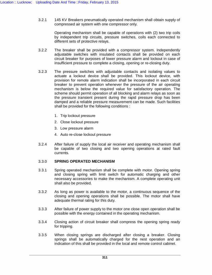
311
3.2.1 145 KV Breakers pneumatically operated mechanism shall obtain supply of
compressed air system with one compressor only. Operating mechanism shall be capable of operations with (2) two trip coils
by independent trip circuits, pressure switches, coils each connected to different sets of protective relays.
3.2.2 The breaker shall be provided with a compressor system. Independently
adjustable switches with insulated contacts shall be provided on each circuit breaker for purposes of lower pressure alarm and lockout in case of insufficient pressure to complete a closing, opening or re-closing duty.
3.2.3 The pressure switches with adjustable contacts and isolating values to
actuate a lockout device shall be provided. This lockout device, with provision for remote alarm indication shall be incorporated in each circuit breaker to prevent operation whenever the pressure of the air operating mechanism is below the required value for satisfactory operation. The scheme should permit operation of all blocking and alarm relays as soon as the pressure transient present during the rapid pressure drop has been damped and a reliable pressure measurement can be made. Such facilities shall be provided for the following conditions :
1. Trip lockout pressure
2. Close lockout pressure 3. Low pressure alarm 4. Auto re-close lockout pressure
3.2.4 After failure of supply the local air receiver and operating mechanism shall
be capable of two closing and two opening operations at rated fault currents.
3.3.0 SPRING OPERATED MECHANISM
3.3.1 Spring operated mechanism shall be complete with motor. Opening spring
and closing spring with limit switch for automatic charging and other necessary accessories to make the mechanism. A complete operating unit shall also be provided.
3.3.2 As long as power is available to the motor, a continuous sequence of the
closing and opening operations shall be possible. The motor shall have adequate thermal rating for this duty.
3.3.3 After failure of power supply to the motor one close open operation shall be
possible with the energy contained in the operating mechanism.
3.3.4 Closing action of circuit breaker shall compress the opening spring ready for tripping.
3.3.5 When closing springs are discharged after closing a breaker. Closing
springs shall be automatically charged for the nest operation and an indication of this shall be provided in the local and remote control cabinet.
Location :: Lucknow; Uploading Date And Time ::Friday, February 13, 2015
312
3.3.6 Provisions shall be made to prevent a closing operation of the breaker
when the spring is in the partial charged condition. Mechanical interlocks shall be provided in the operating mechanism to prevent discharging of closing springs when the breaker is already in the closed position.
3.3.7 The spring operating mechanism shall have adequate energy stored in the
operating spring to close and latch the circuit breaker against the rated making current and also to provide the required energy for the tripping mechanism if case the tripping energy is derived from the operating mechanism.
3.3 OPERATING MECHANISM HOUSING
3.3.1 OPERATING MECHANISM AND ALL ACCESSORIES SHALL BE ENCLOSED IN A WEATHER PROOF. VERMIN PROOF MECHANISM CABINET OF HIGH STRENGTH EPOXY BASE PAINTED/ GALVANIZED STEEL SHEET CONSTRUCTION OF APPROPRIATE THICKNESS HINGED DOORS GIVING ACCESS TO THE MECHANISM AT THE FRONT SHALL BE PROVIDED. SUITABLE GASKETS SHALL BE PROVIDE TO MAKE THE MECHANISM HOUSING WATER PROOF. DUST AND VERMIN PROOF. THE HOUSING LATCH SHALL ACCOMMODATE PAD LOCK REQUIRING A 12 MM DIA HOLE PAD LOCK AND DUPLICATE KEYS SHALL BE FURNISHED BY THE BIDDER. A COMMON MARSHALLING BOX FOR THE THREE POLES OF THE BREAKER SHALL BE PROVIDED ALONG WITH SUPPLY OF TUBING
3.3.2 THE OPERATING MECHANISM SHALL HAVE
ALUMINUM CASTING SUITABLE FOR OUTDOOR DUTY. CONTROL COILS AND AUXILIARY SWITCHES SHALL BE FIXED ON OPERATING MECHANISM. ALL ELECTRICAL ACCESSORIES INCLUDING HEATER OTHER THAN CONTROL COILS AND AUXILIARY SWITCH SHALL BE MOUNTED INSIDE ONE COMMON CONTROL CABINET (MARSHALLING BOX) WHICH SHALL BE MADE OF 2MM THICK SHEET STEEL. ALL MECHANICAL AND ELECTRICAL COMPONENTS INSIDE THE CABINET SHALL BE MOUNTED ON ANGLED FRAME. THE CABINET SHALL BE DULY PAINTED AND IP55 PROTECTED SUITABLE FOR OUT DOOR PURPOSE. THE CUBICLE SHALL HAVE PADLOCK ARRANGEMENT ON DOOR.
3.3.3 SUITABLE 230 VOLTS A.C. HEATERS SHALL BE AMOUNTED IN THE HOUSING TO PREVENT CONDENSATION AND SHALL BE CONTROLLED BY THERMOSTAT SO THAT THE CUBICLE TEMPERATURE IS ALWAYS MAINTAINED APPROXIMATELY 10 DEG C ABOVE THE OUTSIDE AIR TEMPERATURE. ON/OFF SWITCH AND FUSES/MCB SHALL ALSO BE PROVIDED.
Location :: Lucknow; Uploading Date And Time ::Friday, February 13, 2015
313
3.3.4 TERMINAL BLOCK SHALL BE FURNISHED IN THE
MECHANISM HOUSING. TERMINALS FOR D.C. AND A.C. SHALL BE PROVIDED SEPARATELY AND ISOLATED FROM EACH OTHER. TERMINAL FOR THE CONTROL AND OTHER CIRCUIT SHALL BE SUITABLE FOR ACCOMMODATING 3 CORE 2.5MM2 COPPER CONDUCTOR CABLE LEADS. SPARE TERMINALS FOR CONTROL WIRING SHALL BE PROVIDED. ALL WIRING IN THE HOUSE SHALL BE OF STANDARD INSULATING MATERIAL AND SHALL BE SUCH THAT IT SHALL NOT SUPPORT COMBUSTION. SUITABLY RATED SWITCHES FOR A.C. SUPPLY SHALL BE PROVIDED IN THE MECHANISM TO ENABLE THE CONTROL SUPPLY TO THE BREAKER TO BE CUT OFF. A LIGHT POINT WITH A CONTROL SWITCH SHALL ALSO BE PROVIDED.
4.0 TERMINAL BLOCK AND WIRING :
4.1 TERMINAL CONNECTORS IN THE TERMINAL BLOCK SHALL BE OF ELMEX MAKE AND HAVE THE FOLLOWING FEATURES AND MUST BE PROVIDED WITH SHORTING AND DISCONNECTING LINKS TO FACILITATE ISOLATION OF ANY DESIRED CONNECTION OR CIRCUIT.
4.2 FOR THE SAFE CONTACT CONDITION AND LIGHTNESS OF SCREWS THE TERMINAL BODY, BRIDGE, PRESSURE PAD AND THE SCREWS SHALL BE OF HIGH STRENGTH BRASS. THE OUTER SURFACES OF ALL METAL PARTS SHALL BE COATED SUITABLY FOR PROTECTION AGAINST ATMOSPHERIC EFFECT.
4.3 SCREW LOCKING
All the screws shall be secured by reaction principals against unintentional self loosening.
4.4 THREADING
The threading parts shall be such that if the screws are adequately tightened for checking purposes it shall not break or become free. For studs and screws female threads shall be provided by using flawless taps to get strong threads.
4.5 CLAMPING OF CONDUCTORS
Terminal connector shall be such that the conductor can be fixed with adequate contact pressure and without undue damage to the conductor. While tightening the screws/nuts the terminal connectors shall not move or get displaced. For easy connections of even the thinnest conductor and providing rigid connections without any damage, the bottom of the terminal body shall be flat. The terminal connector shall also be suitable for accommodating at least 3 crores of 2.5 sq. mm., copper conductor cable without any preparation viz. lugs, clamping soldering etc. The contact pressure shall not be transferred through insulating material. Gripping of conductor shall be made effective by a pressure pad between metal surfaces only.
Location :: Lucknow; Uploading Date And Time ::Friday, February 13, 2015
314
4.6 TERMINAL BLOCK HOUSING These shall be made from high grade melamine, thermosetting molding
powder having the highest unit tracking property. The impact strength shall be in between 0017-0019 kg-m tested in accordance with clause 0.3.2 table 1 of IS:3669 B-1966, testing method must be adopted as per clause II of IS 2221 of 1962.
4.7 TERMINAL BLOCKS Terminal blocks shall be of disconnecting type.
4.8 SHORTING LINKS
Circuit Isolation Link The circuit isolation link shall be provided in each and every connector of
terminal blocks.
Shorting Links The provision of permanent (removable) shorting links in each terminal
connector shall be done (whenever required), so that any two adjacent terminals can be shorted effectively (maximum) to consecutive five terminal Connectors.
4.9 MOUNTING DEVICE
The terminals shall be mounted by clipping action at two points on the aluminum/steel channel as per DIN 46277/1 and these shall be easily removable without affecting the mounting of adjacent terminals.
4.10 MARKING/ LABLES/FERRULES/TERMINAL NOS
The marking labels on each side of ends shall be fitted permanently with duly engraved descriptions. The embossing shall be of permanent type scratch proof and suited to tropical climatic condition. The size shall be such that these may easily be inserted on the P.V. C. insulation 2.5mm2, copper conductor cable and shall not come out itself.
4.11 MOUNTING FOR TERMINALS The terminal connectors shall be mounted in such a fashion that
connections are made on lifting up the disconnecting link. 4.12 END CLAMPS
To avoid side ward movement and to hold the terminals closely together, the end clamps shall be provided at both the ends of the terminal.
4.13 TESTING BUSH AND SCHEMATIC DIAGRAM The testing bushes shall be provided on the top and bottom of each
terminal of terminal block. A schematic diagram shown on a PVC plate with screen printing of permanent nature (non-scratch able, clearly visible) shall be riveted / affixed on the side of control cubicle door. Similarly the terminal block arrangement on separate plate shall be riveted on the control/cubicle door.
Location :: Lucknow; Uploading Date And Time ::Friday, February 13, 2015
315
4.14 COLOUR OF TERMINAL BLOCKS The following colours of terminal blocks shall be used:
a) For A.C. circuit terminal block : Red colour B) FOR D.C. CIRCUIT
TERMINAL BLOCK CONVENTIO
NAL COLOUR
4.15 VOLTAGE AND CURRENT CARRYING CAPACITY The rating of terminal connector shall be of 15 Amps. and 250 volts D.C for
uninterrupted duty, complete with insulting barriers at both end of terminal block (if necessary).
4.16 ELECTRICAL TRENCH
Terminal connector housing shall be provided with a through and through running recess i.e. electrical trench on both sides of terminal for removing dust with blower.
5.0 A.C. CIRCUITS
5.1 HEATERS
The controlling fuse/MCB, link and switch/MCB for the heater shall be provided in its own pole cabinet. The thermostat at a preset of 50 deg C permanently shall be provided in the cubicle to control the individual heater.
5.2 D.C. CIRCUIT
No local fuse and links shall be provided in the circuit breakers cubicle for the D.C. circuits. Suitable rotary switch/MCB shall be provided in such cases.
5.3 AUXILIARY CIRCUIT BREAKERS CONTACTS (USED IN TRIPPING
AND CLOSING CIRCUITS) Circuit breaker’s auxiliary contacts used in the tripping/closing circuit for
breaking of tripping/closing currents shall be rated for not less than 10 Amps. 110 Volts D.C. The material of contacts and their arrangement shall be such that the contact resistance shall be minimum to avoid unnecessary heating and contact pressure shall not reduce before at least 10,000 operations.
5.4 PRESSURE LOCKOUT CONTACTOR For the purpose of locking out, an auxiliary contactor in conjunction with
air/gas pressure switch in closing/tripping circuits to be used. The following colour shall be used in the wiring :
A.C. circuit : Black
D.C. circuit : Grey
Earthing : Green
Location :: Lucknow; Uploading Date And Time ::Friday, February 13, 2015
316
6.0 BUSHING AND INSULATORS 6.1 Porcelain used for bushing shall be homogenous free from lamination,
cavities and other flaws or imperfections that might affect the mechanical or dielectric quality and shall be thoroughly vitrified, tough and impervious to moisture.
6.2 Glazing of the porcelain shall be uniform and brown in colour, free from
blisters, bums and other defects. Bushing shall be designed to have ample insulation, mechanical strength and rigidity for the conditions under which they will be used all bushings of identical rating shall be interchangeable.
6.3 Puncture strength of bushings shall be greater than flashover value. When
operating at normal rated voltage, there shall be no electric discharge between the conductor and bushings which would cause corrosion or injury to conductors, insulators, or supports by the formation of substances produced by chemical action. No radio disturbance shall be caused by the bushings when operating at the normal rated voltage.
6.4 All iron parts shall be given zinc chrome coating hot dip galvanized and all
joints shall be airtight. Surfaces of the joints shall be airtight. Surface of the porcelain parts shall be made smooth by grinding and metal parts by machining. Bushing design shall be such as to ensure a uniform compression on the joints.
6.5 The basic insulation level of the bushings, insulating porcelains and the
external insulator supports etc. shall be 1050KV (peak) and shall be suitable for insulation in heavily polluted atmosphere with minimum total creepage distance of 6125mm as per relevant IEC. The minimum clearance in air between phases and live parts to earth shall be as per relevant IEC.
6.6 The high pressure air passage in the hollow insulator should be protected
by suitable insulating tube which should withstand static. Air pressure equal to twice the normal working pressure.
6.7 Oil filled bushing should be free from oil leakage and should be designed to
prevent accumulation of explosive gases and to provide adequate oil circulation to remove internal heat. Adequate means should be provided to accommodate conductor expansion and there should not be any undue stressing of any part due to temperature changes. They should be equipped with liquid level indicators and means for sampling and draining oil from the nushings.
7.0 CONTACTS :
7.1 Main contacts shall have ample area and contact pressure for carrying the
rated current and the short time rated current of the breaker without excessive temperature rise which may cause pitting or welding. Contacts shall be easily replaceable and shall have a minimum of movable parts and adjustments to accomplish these results. Main contacts shall be the first to open and the last to close so that there will be little contact burning and wearing.
Location :: Lucknow; Uploading Date And Time ::Friday, February 13, 2015
317
7.2 Arcing contacts, if provided, shall be the first to close and last to open and
shall be easily accessible for inspection and replacement. Tips of arcing and main contacts shall be silver plated or have a tungsten alloy tipping.
8.0 INTERLOCKS
8.1 All the three poles shall trip simultaneously on a pneumatic/electrical
command. Pole discrepancy timer relay shall be supplied with each breaker to trip the breaker as well as to give a remote trip discrepancy alarm.
8.2 The following air / gas pressure alarm / inter lock shall be provided on the
circuit breaker each with 2 contacts : i. Low pressure pre-locking alarm switch ii. Low pressure closing / tripping lockout interlock.
iii. Low pressure auto re-closing lockout interlock. 9.0 AUXILIARY SWITCHES
9.1 Each circuit breaker shall be provided with10 normally open & 10 normally
closed cotacts on each pole and 12 normally open and 12 normally closed contacts common for all three pole operations. All switches shall be positively driven (not by spring) in both directions.
9.2 Normal position of auxiliary switches refers to contact position when circuit
breaker is open. 10.0 PNEUMATIC SYSTEM All compressed air cabin connections specially between ceramic and
metallic components shall be completely tight for pressures up to twice the rated pressure for breaker operation. The gaskets used for these joints shall have a long life under climatic conditions as already specified in this specification. Necessary arrangement for draining the condensed moisture from the lower points in the pneumatic system should be incorporated.
11.0 UNIT COMPRESSED AIR SYSTEM 11.1 Each SF6 Circuit Breaker should consist of two number unit compressors.
Each compressor shall be capable to feed air for all operations of the circuit breaker satisfactorily. The other compressor shall be as stand by for emergency purposes although both will run simultaneously. All necessary electrical/pneumatic connections between compressors and each pole of circuit breaker shall be carried out by Bidder.
11.2 The initial filling time of the compressed air system shall not be more than 72.75 minutes (approx) with compressor running under normal operating conditions. The minimum running time of the compressor for replenishing the air system from the present starting pressure to the rated pressure shall not be more than 10 minutes. The flow capacity of all the valves shall be at least 20% greater than the total compressor capacity.
Location :: Lucknow; Uploading Date And Time ::Friday, February 13, 2015
318
11.3 The complete details of compressor unit air receivers, the automatic control
equipment and other accessories included in the plant shall also be supplied along with the breaker and compressor units. The complete system scheme and layout of automatic control equipment and air compressor equipment shall be furnished with circuit breaker/compressor plant.
11.4 A clock / counter shall be provided in the control cubicle of the compressor unit for registering the total nos. of operations / cumulative operation time of the compressor unit.
11.5 The Unit compressed air system shall meet the following requirements:- a) The compressed air system shall be provided with necessary piping,
piping accessories, control valves, safety valves, filters, reducing valves, isolating valves, drain ports etc. Also the unit compressed air system shall be provided with suitable anti-vibration pads.
b) The compressors shall be of air cooled type and mounted within the operating mechanism housing OR on civil foundation with canopy(cover).
c) The air receiver shall have stored energy for 2 CO operations of the breaker at the blocking pressure for auto re closing duty without refilling. The unit compressor shall be capable of building up required pressure for another 2 CO operations within 30 minutes.
11.6 Air Compressor a. The air compressor shall be of air cooled type complete with cylinder
fabrication, drive motor etc. The compressor shall be rated for the following duty :
i. Total running time of Compressor to build up the Rated pressure from Atmospheric pressure.
Not exceeding 80 minutes
ii. Normal running air changing Not exceeding 15 minutes considering 10% leakage per day
iii. Air changing time after one Close-open operation from Rated pressure
Not exceeding 15 minutes
b. Compressor shall be driven by automatically controlled motors conforming to the requirements.
c. The compressor shall be provided with automatic adjustable unloading device during starting.
11.7 Air Receivers a. Air receiver shall be designed in accordance with the latest edition of the
ASME Code for Pressure Vessel – Section VIII of BS 5179 A corrosion allowance of 3.0 mm shall be provided for shell and dished ends.
Receivers shall be hot dip galvanized. b. Connections for air inlet and outlet, drain and relief valves shall be flanged
type or screwed type only. c. Accessories such as suitable sized safety valve to relieve full compressor
discharge at a set pressure equal to 1.1 times the maximum operating
Location :: Lucknow; Uploading Date And Time ::Friday, February 13, 2015
319
pressure, blow off valve, auto drain tap with isolating and by-pass valve, dial type pressure gauge and drain valve and test connection shall be provided.
d. Air receiver shall have at least 50% spare capacity, calculated on the basis of total air requirement for 2 CO operations.
11.8 Quality of Air Compressed air used shall be dry and free of dust particle and fully
compatible with the materials used in the pneumatic operating mechanism. Arrangement for conditioning the compressed air if required shall be provided as an integral part of air compressor system.
11.9 Control and Control Equipment a. The compressor control shall be of automatic start/stop type initiated by
pressure switches. b. All the necessary compressor control equipment shall be housed in a totally
enclosed sheet steel cabinet also conforming to requirements. Pressure gauges and other indicating devices control switches shall be mounted on the control cabinet.
c. A glass window shall be provided for viewing the indicating instrument/ gauges.
11.10 Compressed Air Piping, Valves and Fittings
a. The flow capacity of all valves shall be a least 20% greater than the total compressor capacity.
b. The high pressure pipe and air system shall be such that after one O-0.3 sec-CO operation the breaker shall be capable of performing one CO operation within 3 minutes.
c. All compressed air piping shall be bright annealed, seamless phosphorous Deoxidized Non-Arsenical Copper alloy as per BS : 2874 or stainless steel pipe (C-106 of BS : 2871-1957)
d. All joints and connections in the piping system shall be brazed or flared as necessary.
e. All compressed air piping shall be carried out in accordance with BS : 162. f. Compressed air piping system shall be completed with Saddle clamps to
support the piping system at suitable intervals. Necessary bolts, nuts, pipe fixing clamps etc. shall be included in the Scope of Bidder.
11.11 Tests In accordance with the requirement, the compressors and its accessories
shall conform to type tests and routine tests as per applicable standards. 12.0 TERMINAL CONNECTORS 12.1 6 nos. terminal connectors shall be provided with each circuit breaker.
These shall be suitable for ACSR ZEBRA conductor. The terminal pad of equipment and terminal connector shall be manufactured from same materials i.e., Aluminum alloy. The temperature of the clamps shall not exceed 80 deg C Corona rings shall be provided at the breaker terminal, if required.
Location :: Lucknow; Uploading Date And Time ::Friday, February 13, 2015
320
12.2 Two clamp type grounding terminals, each suitable for clamping the
grounding conductor, shall be provided on each circuit breaker. 12.3 Terminal connector should be designed for current ratings and shall comply
in all respects including temperature rise, resistance, tensile strength and short circuit current withstand capacity tests as specified in IS:5561-1970 or latest revision thereof.
13.0 SULPHUR HEXAFLUORIDE GAS (SF6) a. The SF6 gas shall comply with IEC-376, 376A and 376B and shall be
suitable in all respects for use in the switchgear under the operating conditions.
b. The high pressure cylinders in which the SF6 gas is shipped and stored at site shall comply with requirements of the following standards and regulations:
IS:4379– Identification of the contents of industrial gas cylinders. IS:7311–
Seamless high carbon steel cylinders for permanent and High pressure liquefiable gases.
c. The SF6 gas shall, be tested for purity, dew point air hydrolysable fluorides and water contents as per IEC-376, 376-A and 376-B and test certificates shall be furnished to Purchaser.
14.0 SPECIFIC REQUIREMENT OF SF6 C.B. 14.1 Circuit breakers shall be of single pressure type with two air compressor for
pneumatic operations. Circuit breakers shall be so designed that upon loss of pressure the gap between open contacts shall be suitable to withstand at least the rated voltage at zero gauge pressure of gas.
14.2 Design and construction of the circuit breaker shall be such that there shall be no possibility of gas leakage and moisture content.
14.3 In the interrupter assembly there shall be an absorbing product box to eliminate SF6 decomposition products and moisture.
14.4 When pole unit (interrupter) is removed SF6 gas shall not drain out from the pole. Facility shall be available so that a complete pole unit can readily be replaced by another pole unit without disturbing the other poles.
14.5 Material used in the construction of circuit breakers shall be such as to fully compatible with SF6.
14.6 Each pole shall form an enclosure filled with SF6 gas. The pressure of pole shall be monitored and regulated by individual pressure switches. Adequate O-ring seals with test hole for leakage test of the internal seal shall be provided on each static joint.
14.7 Sufficient SF6 gas shall be provided to fill all the breakers installed at a
substation. Rate of leakage of SF6 gas shall not be more than 1% per year. 14.8 The circuit breaker shall have facilities as to reduce the gas pressure within
the circuit breaker to a value not exceeding 8 mill bars within 4 hours or less. The breaker shall be capable of withstanding this degree vacuum without distortion or failure of any part.
Location :: Lucknow; Uploading Date And Time ::Friday, February 13, 2015
321
14.9 The Circuit Breakers shall be designed for pressure withstand values, much
higher than the rated operating pressures to minimize damages to operators in the event of gas or vapors escaping under pressure.
14.10 SF6 gas shall comply with IEC-376 and be suitable in all respects for use in
circuit breakers under the operating conditions.
14.11 The high pressure cylinders, in which the SF6 gas is dispatched and stored at site, shall comply with the requirements of the local regulation and by-laws.
14.12 Sufficient SF6 gas shall be provided to fill all the circuit breakers installed
plus an additional 20% of the quantity to compensate for losses during future operations.
15.0 MOUNTING STRUCTURE
15.1 The circuit breaker shall be suitable for mounting directly on plinth. Suitable
steel structures, supporting column for mounting the circuit breakers shall also be supplied along with the breaker. The steel structures shall be pillar/lattice type and galvanized as per relevant IS. The drawing of the offered steel structure should be sent with each breaker along with other technical details etc.
16.0 INTERPOLE WIRING
Necessary electrical wires/air pipes required or inter pole connections shall
also be in the scope of supply. All cables to be used by Bidder shall be armored and shall be as per IS-1544 (1100 volts grade) only copper conductor shall be used. Minimum size of conductor shall be 2.5 sq. mm (copper).
17.0 INSULATION REQUIREMENT OF CIRCUIT BREAKERS
The insulation phase to ground, the insulation between open contacts and
the insulation between phases of the completely assembled circuit breaker shall be capable of withstanding satisfactorily dielectric test voltage corresponding to the basic insulation level of 1050KV (peak).
The minimum clearance in air between phases and live parts to earth
should be as per IEC. The breaker poles should be suitable to be placed 4.5 meters apart center to center.
Location :: Lucknow; Uploading Date And Time ::Friday, February 13, 2015
322
18.0 FITTING AND ACCESSORIES
Following fittings and accessories shall be provided as an integral part of the
equipment. i. Pneumatic operating mechanism housing completes with provisions of
padlocks and keys. ii. Space heaters with automatic thermostat control. iii. Two unit compressors with common air receiver for 245 KV Breaker &
One unit compressor with air receiver for 145 KV Breaker iv. Operation counter v. Pressure gauges vi. Gas density detectors (Temperature compensated pressure switch) vii. Local/remote change over switch. viii. Manually operated tripping push button/lever (mech.), conveniently
located to trip all 3 phases simultaneously ix. Control switch to cut off control power supply (A.C. supply only). x. Fuses as required xi. Two earthing terminals xii. Anti pumping relay xiii. Pole discrepancy relay xiv. Rating and diagram plate as per IEC. xv. Main jumper terminal connectors (6 nos.) xvi. Spare 20% SF6 gas with cylinder.
19.0 NAME PLATE Each circuit breaker shall be provided with a name plate and following
information shall be provided :
i. Manufacturers name and trade mark. ii. Serial No. iii. Rated voltage iv. Rated insulation level v. Rated frequency
Location :: Lucknow; Uploading Date And Time ::Friday, February 13, 2015
323
vi. Rated normal current vii. Rated short circuit breaking current viii. Weight ix. Rated duration of short circuit. x. Rated supply voltage of closing and opening device. xi. Rated pressure of compressed gas supply for operation. xii. Specification No. xiii. Year of supply xiv. Name of Purchaser
20.0 TYPE TESTS
The Bidder shall furnish the certified copies of type tests already carried out on
offered 145 KV SF-6 circuit breaker. They shall include but not limited to the following tests-
a) Making capacity breaking capacity and short time current rating tests. b) Operation tests and mechanical endurance tests. c) Temperature rise tests of the main and auxiliary circuits and measurement
of the resistance of the main circuit. d) Impulse voltage dry and wet withstand tests and one minute power
frequency voltage dry and wet withstand test. e) Line charging breaking current test. f) Tests to prove the rated transient recovery voltage and RRRV of the circuit
breaker. g) Short line fault tests. H) Out of phase switching tests I) Braking small, inductive current test. j) Switching impulse voltage test. k) Measurement of RIV level. l) Partial discharge test. m) Corona extinction voltage tests. ROUTINE TESTS
20.1 The Bidder shall completely assemble and test each SF6 circuit breaker in accordance with IEC-62271-100 amendment there of to ensure satisfactory working of all the component parts and assembled breaker as a whole.
20.2 Following routine tests, whether included in the manufacturer’s routine test or
not, shall be carried out on each circuit breaker.
20.2.1 One minute power frequency voltage dry withstand test as per IEC-62271-100
Location :: Lucknow; Uploading Date And Time ::Friday, February 13, 2015
324
(i) At 110% of rated voltage and maximum pressure (ii) At 70% of rated voltage and minimum pressure (iii) At rated voltage and rated pressure (iv) Tripping at 70% of rated voltage and minimum pressure
20.2.2 Measurement of the resistance of the main circuits as per IEC 62271-100. 20.2.3 Speed curves for each circuit breaker shall be obtained with the help of suitable
operation analyzer to determine breaker contact movement during opening, closing auto-re closing and trip free operation under normal as well as limiting operating conditions (control voltage) pneumatic pressure etc. The test shall show the speed of contact at various stages of operation, travel of contact opening, opening time, closing time, shortest time between separation and meeting of contact at break/make operation etc.
20.2.4 High voltage test on control and auxiliary circuits. 20.2.5 Routine test performed on breaker operating mechanism as per IEC. 20.2.6 Routine test reports of compressor unit associated with the circuit breaker shall
be furnished. 20.2.7 Routine test report of terminal connectors shall be furnished in accordance to
IS-5561-1970.
21.0 SITE TESTS 21.1 The test mentioned under clause nos.20.2.2, 20.2.3 and 20.2.4 shall be
conducted on the completely assembled breaker at site
21.2 All vessels / accessories which operate under pressure shall be tested according to relevant standards and six copies of the test certificate incorporating the following minimum information shall be submitted for each breaker.
Description of item, Bidder/manufacturer sl. no., date of manufacture and test,
drawing’s number, material composition, working and design pressure, details of test carried out and reference standards, test results identification, mark, name and seal of approval of testing authority shall be furnished by the Bidder.
Location :: Lucknow; Uploading Date And Time ::Friday, February 13, 2015
325
TS-2 B
TECHNICAL SPECIFICATIONS OF 36 KV VACUUM CIRCUIT BREAKERS
1.0 STANDARD The 36KV Vacuum circuit breaker shall comply with the requirements of
latest issue of IEC-62210 except where specified otherwise in this specification. Equipment having better quality than the standards mentioned may also be considered provided documentary evidences are furnished.
2.0 PRINCIPLE PARAMETERS The 36KV Vacuum circuit breaker shall be suitable for outdoor operation in
solidly grounded system under climatic conditions specified and should have the following ratings:-
i) Nominal system voltage 33 KV ii) Highest system voltage 36 KV iii) Rates voltage 36 KV iv) Interrupting capacity 1000 MVA v) Rated normal current 1250 A vi) Rated frequency 50 c/s vii) Rated basic insulation level 170 KV viii) Rated short circuit current 25 KA ix) Rated short circuit making current 35 KA x) Rated operating sequence 0-0. 3 Sec.-Co-3 min-Co xi) Total break time for any current
up to the rated breaking current 5-6 c/s
xii) Control circuit voltage 110 VDC 3.0 GENERAL 3.1 The 36KV Vacuum circuit breaker shall be supplied as a complete unit in all
respects. 3.2 The Vacuum circuit breakers shall provide for rapid and smooth interruption
of current under all conditions, completely suppressing all undesirable phenomenons, even under the most severe conditions or while interrupting small currents, loading or logging reactive currents. The rate of rise of restriking voltage across the circuit breaker, switching on inductive or capacitive load, should not exceed 2,5 times the normal phase to neutral
Location :: Lucknow; Uploading Date And Time ::Friday, February 13, 2015
326
voltage. The total break time for the circuit breaker throughout the range of their operating duly shall be stated in the Bid and guaranteed particulars of the breaker.
3.3 MOUNTING The circuit breaker shall be suitable for mounting on galvanized steel
structures. The prices of necessary structures for mounting the circuit breakers shall be included in the cost of circuit breakers.
3.4 CONSTRUCTION 3.4.1 The circuit breaker shall consist of three identical phases used with a
common operating mechanism 3.4.2 Circuit breaker should include the prices of necessary special tools for the
erection & maintenance. List of such tools should be furnished with the Bid. 3.5 OPERATING DUTY Operating duty of the breaker should be 0-0.4 Sec. CO-3 min-CO. 3.6 TEMPERATURE RISE The maximum temperature attained by any part of the equipment, when in
service at site under continuous full load condition and exposed to the direct rays of sun, shall not exceed the permissible limit specified in the relevant standard. When the standards specify limits of temperature rise, these shall not exceed when corrected for the difference between ambient temperature at site and the ambient temperature specified in the approved specification.
3.7 INSULATION OF CIRCUIT BREAKER
The insulation to ground between open contact and between phases of the
completely assembled circuit breakers shall be capable of withstanding satisfactorily dielectric test voltage corresponding to the basic insulation level i.e. 170 KV.
3.8 OPERATING MECHANISM 3.8.1 General 3.8.2 The circuit breaker operating mechanism shall be highly reliable and will
have sufficient energy to provide full making and latching current ability of all the poles simultaneously.
3.8.3 The circuit breakers shall be power operated by motorized spring
mechanism. The three poles of the breaker shall operate simultaneously through a mechanical coupling.
3.8.4 The operating mechanism shall be strong, positive quick and removable
without disturbing other parts of the breaker. The mechanism of breaker shall be a such that the failure of spring will not prevent tripping. The
Location :: Lucknow; Uploading Date And Time ::Friday, February 13, 2015
327
mechanism shall be trip free electrically and mechanically.
3.8.5 All working parts in the mechanism shall be of corrosion resistant material
and all bearings which require grossing shall be equipped with pressure grease fittings.
3.8.6 Suitable anti pumping feature shall be incorporated in the circuit breaker.
There shall be no objectionable rebound and the operating mechanism shall not require any critical adjustment.
3.8.7 It shall be strong, rigid, positive and fast in operation, Provision shall be
made for local electrical control and local/remote selection with enough contacts in the cubicle of the breaker. Manual emergency local tripping arrangement shall be provided on the breaker for use in emergency during maintenance. This emergency trip is intended for use, shall a failure of any part of D.C. control circuits including trip coil takes place preventing remote electrical tripping.
The control circuits shall be designed to operate on 110V DC 3.8.8 Breaker shall be provided with ON/OFF mechanical indicator in position so
that a man standing on ground may easily see it, with the mechanism housing closed. The operation counter shall be provided.
3.8.9 Electrical tripping of the breaker shall be performed by shunt trip coil. A
shunt trip coil shall operate correctly under all operating conditions of the circuit breaker and all values of supply voltage between 70% to 110% of the rated voltage. A closing release shall operate correctly at all values of voltage between 80% to 110% of the rated voltage.
3.8.10 Working parts of the mechanism shall be made of corrosion resisting
material. Bearings which require grease shall be equipped with pressure type grease fittings. Bearing pins, bolt-nuts and other parts shall be adequately pinned or locked to prevent loosening or changing adjustment with repeated operation of the breaker.
3.8.11 Power supply for auxiliaries will be available at 415 volts 3 phases 50 hertz,
230 volts, single phase, 50 Hertz or 110 volts D.C. 4.0 OPERATING MECHANISM HOUSING 4.1 Operating mechanism and all accessories shall be enclosed in a weather
proof cabinet of high strength steel sheet construction, the thickness of which shall not be less than 2 mm. Hinged doors giving access to the mechanism at the front shall be provided. Suitable gaskets to make the mechanism housing water proof, dust proof and vermin proof. The housing latch shall accommodate padlock. A common marshalling box for the three poles of the breaker shall be provided suitable 230 volts A.C. heaters shall be mounted in the housing to prevent condensation, so that the cubicle temperature is always maintained approximately 100C above the outside air temperature.
Miniature circuit breaker shall also be provided. Terminal board shall be
furnished in the mechanism housing. Terminals for D.C. shall be isolated
Location :: Lucknow; Uploading Date And Time ::Friday, February 13, 2015
328
for each other. Terminal for the control and other circuits shall be suitable for accommodating 2.5 sq.mm. stranded copper conductor cable leads. Spare terminals for control wiring in the housing shall be provided. Insulation material shall be such that it shall not support combustion, suitable rated switches for A.C. supply shall be provided in the mechanism to enable control supply of the breaker to be cut off. A 5A, 3 pin plug point with a control switch shall be provided.
5.0 BUSHING AND INSULATORS 5.1 Porcelain used for bushing shall be homogenous, free from lamination,
cavities and other flaws of imperfections that might affect the mechanical or dielectric quality and shall be thoroughly vitrified, tough and impervious to moisture.
5.2 Glazing of the porcelain shall be uniform and brown in colour, free from
blisters, burns and other defects. Bushing shall be designed to have ample insulation, mechanical strength and rigidity for the conditions under which they will be used. All bushing of identical rating shall be interchangeable.
5.3 Puncture strength of bushings shall be greater than flashover value, when
operating at normal rated voltage. There shall be no electric discharge between the conductor and bushings which could cause corrosion or injury to conductors, insulators or supports by the formation of substance produced by chemical action, No radio disturbance shall be caused by the bushings when operating at the normal rated voltage.
5.4 All iron parts shall be given hot dip zinc/chrome coating and all joints shall
be air tight. Porcelain parts shall be designed by grinding and metal parts by machining. Bushing design shall be such as to ensure a uniform compression on the joints.
5.5 The basic insulation level, of the breaking chamber porcelain, insulator
supports etc shall be 170KV peak and shall be suitable for insulation in heavily polluted atmosphere with minimum total creepage distance as per relevant IEC.
5.6 The minimum clearance in air between phase and live parts to earth shall be
as per IEC. 5.7 Necessary cable glands for the cables of the operating mechanism shall be
provided along with a large common gland plate. Total requirement and size of the cable glands will be as below: -
1. 2 x 2.5 sq.mm. Cu Cable 4 nos. 2. 4 x 2.5 sq.mm. Cu Cable 5 nos.
3. 6 x 2.5 sq.mm. Cu Cable 3 nos. 4. 10 x 2.5 sq.mm. Cu Cable 1 no.
Location :: Lucknow; Uploading Date And Time ::Friday, February 13, 2015
329
6.0 CONTACTS Main contacts shall have ample area and contact pressure for carrying the
rated current and the short time rated current of the breaker without excessive temperature rise which may cause pitting or welding.
7.0
INTERLOCKS
7.1
Provision shall be made to enable mechanical/electrical interlocking with opening or closing of the isolator with the circuit breaker 3 nos. castel locks with one key for each circuit breaker as well as associated isolators shall be supplied along with the circuit breaker. A switch (KS) which will be actuated by the insertion of key shall be provided
7.2
The following interlocks shall be provided on the vacuum circuit breaker each with 2 contacts.
7.2.1 Spare contact for tripping. 7.2.2
All the three poles of the breaker shall trip simultaneously on an electrical command.
8.0 AUXILIARY SWITCHES 8.1
Circuit breaker shall be provided with 6 normally open and 6 normally closed contacts. All switches shall be driven positively i.e. (not by spring) in both directions.
8.2
Normal position of auxiliary switches refer to contact positions when circuit breaker is open.
9.0 TERMINAL CONNECTORS 6 nos. rigid type aluminum terminal connectors each suitable for ACSR Twin
Panther/ Twin Moose conductor with 90 mm, centre to centre spacing shall be provided with each circuit breaker.
The temperature at the clamp shall not exceed 800C. Two number
grounding terminals suitable for clamping the ground conductor shall be provided on breaker. The terminal connector shall conform in respect of temperature rise, tensile strength and short circuit breaking current withstanding capacity tests etc. as per IS 5561-1970 or its latest revision thereof.
10.0 TERMINAL BLOCK AND WIRING 10.1
Terminal connection in the terminal block shall have the following features and must be provided with shorting links.
10.2
For the safe contact conditions and tightness of screws, the terminals, body bridge, pressure pad and the screws shall be of high strength brass. The outer surface of all metal parts shall be nickel plated for protection against atmospheric effects.
Location :: Lucknow; Uploading Date And Time ::Friday, February 13, 2015
330
10.3
24 nos. terminals for current transformers as spares shall be provided in the circuit breaker cubicle on a separate terminal block. Elmex make terminals shall be provided. These terminals shall have a facility of inserting testing bushes. Four number testing bushes shall also be supplied fitted in the terminal block.
10.4 SCREW LOCKING All the screw shall be secured by reaction principle against unintentional self
loosening. 10.5 THREADING The threading parts shall be such that if the screws are adequately
tightened for checking purposes shall not break or become free. For studs and screws, female threads shall be produced by using flaw less taps to get strong threads.
10.6 CLAMPING OF CONDUCTORS Terminal connector shall be such that the conductors can be fixed with
adequate contact pressure and without undue damage to the conductor, while tightening the screw or nuts, the terminals connectors shall not move or get displaced.
For the easy connections even the cheapest conductor and providing rigid
connections without any damage, the bottom of the terminal body shall be flat.
The terminal connector shall also to suitable for accommodating at least 2
cores of 2.5 sq. mm. copper conductor cable without any pre-operation vis lugs, clamping, soldering etc.
10.7 TERMINAL BLOCKS These shall be made from high grade melamine thermosetting molding
power having the highest unit tracking property. The impact strength shall be between 0017-0019 tested in accordance with clause no. 3.2 table-1 of IS 3669 B-1966. Testing method must be adopted as per clause-II of IS 2221 of 1962. Terminal blocks shall be snap on type to facilitate easy removal of terminal from the channel and thus the dust may be removed from the terminal block housing.
10.8 SHORTING LINKS The provision of permanent (removable) shorting links in each terminal
connector shall be provided (where over required so that any two adjacent terminals can be shorted effectively.
10.9 MOUNTING DEVICE The terminal shall be mounted by clipping action at two points on the
aluminum/steel channel as per DIN 46277 and these shall be easily removable without affecting the mounting of adjacent terminal.
Location :: Lucknow; Uploading Date And Time ::Friday, February 13, 2015
331
10.10 MARKING LABLES The marking labels on each side of ends shall be fitted permanently duly
engraved descriptions. The embossing shall be of permanent type scratch proof and suited to tropical climatic condition. The size shall be such that these may easily as inserted on the P.V.C. insulation of 2.5 mm, copper conductor cable and shall not come out itself.
10.11 DIMENSION OF CLEARANCES AND CREEPAGE DISTANCES This will be such that auxiliary circuitry can withstand the routine test
requirement of 2KV for 1 minute in line with IEC 62210. 10.12 MOUNTING FOR TERMINALS The terminal connectors shall be mounted in such a fashion that
connections are made on lifting up the disconnecting link. 10.13 END CLAMPS To avoid side ward movement and to hold the terminals closely together, the
end clamps shall be provided at both the ends of the terminals. 10.14 COLOUR OF TERMINAL BLOCKS The following colours of terminal blocks shall be used. a) For A.C. circuit terminal block - Red colour. b) For D.C. circuit terminal block - Conventional colour. 11.0 FITTING AND ACCESSORIES :- Following fittings and accessories shall be provided as an integral part of the
equipment. Sl.No. Description of fitments Quantity
1. Vacuum interrupters 3 2. Set of porcelain insulator housingVacuum
interrupter and glass fiber drive rod 3
3. Galvanized steel support structure with foundation bolts
1
4. Three phase interphase assembly connected to common Operating shaft.
1
5. Motor/manually charged independent spring closing mechanism having :-
1
i. Mechanical ON/OFF indicator ii. Spring charged indicator
Location :: Lucknow; Uploading Date And Time ::Friday, February 13, 2015
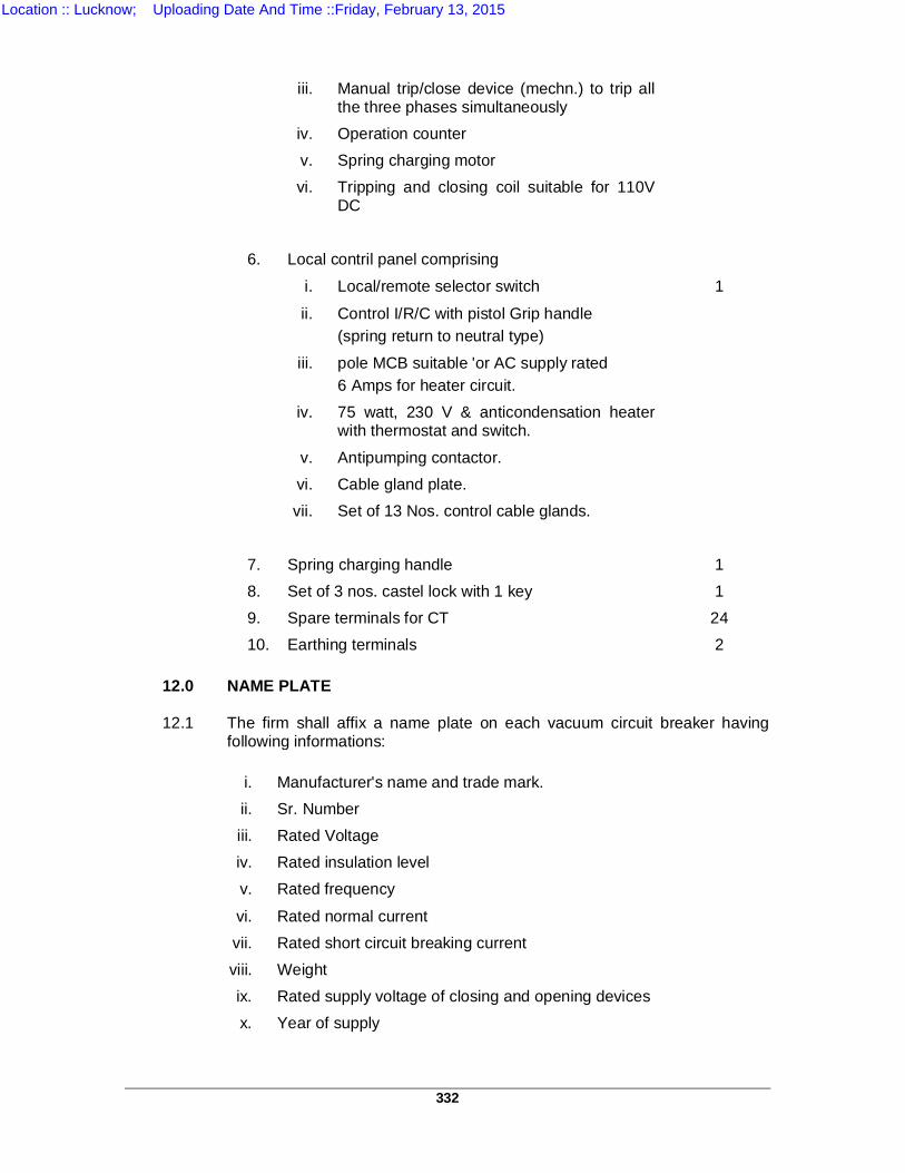
332
iii. Manual trip/close device (mechn.) to trip all the three phases simultaneously
iv. Operation counter v. Spring charging motor vi. Tripping and closing coil suitable for 110V
DC
6. Local contril panel comprising
i. Local/remote selector switch 1
ii. Control I/R/C with pistol Grip handle (spring return to neutral type)
iii. pole MCB suitable 'or AC supply rated 6 Amps for heater circuit.
iv. 75 watt, 230 V & anticondensation heater with thermostat and switch.
v. Antipumping contactor. vi. Cable gland plate. vii. Set of 13 Nos. control cable glands.
7. Spring charging handle 1 8. Set of 3 nos. castel lock with 1 key 1 9. Spare terminals for CT 24 10. Earthing terminals 2 12.0 NAME PLATE 12.1
The firm shall affix a name plate on each vacuum circuit breaker having following informations:
i. Manufacturer's name and trade mark.
ii. Sr. Number iii. Rated Voltage iv. Rated insulation level v. Rated frequency
vi. Rated normal current vii. Rated short circuit breaking current viii. Weight ix. Rated supply voltage of closing and opening devices x. Year of supply
Location :: Lucknow; Uploading Date And Time ::Friday, February 13, 2015
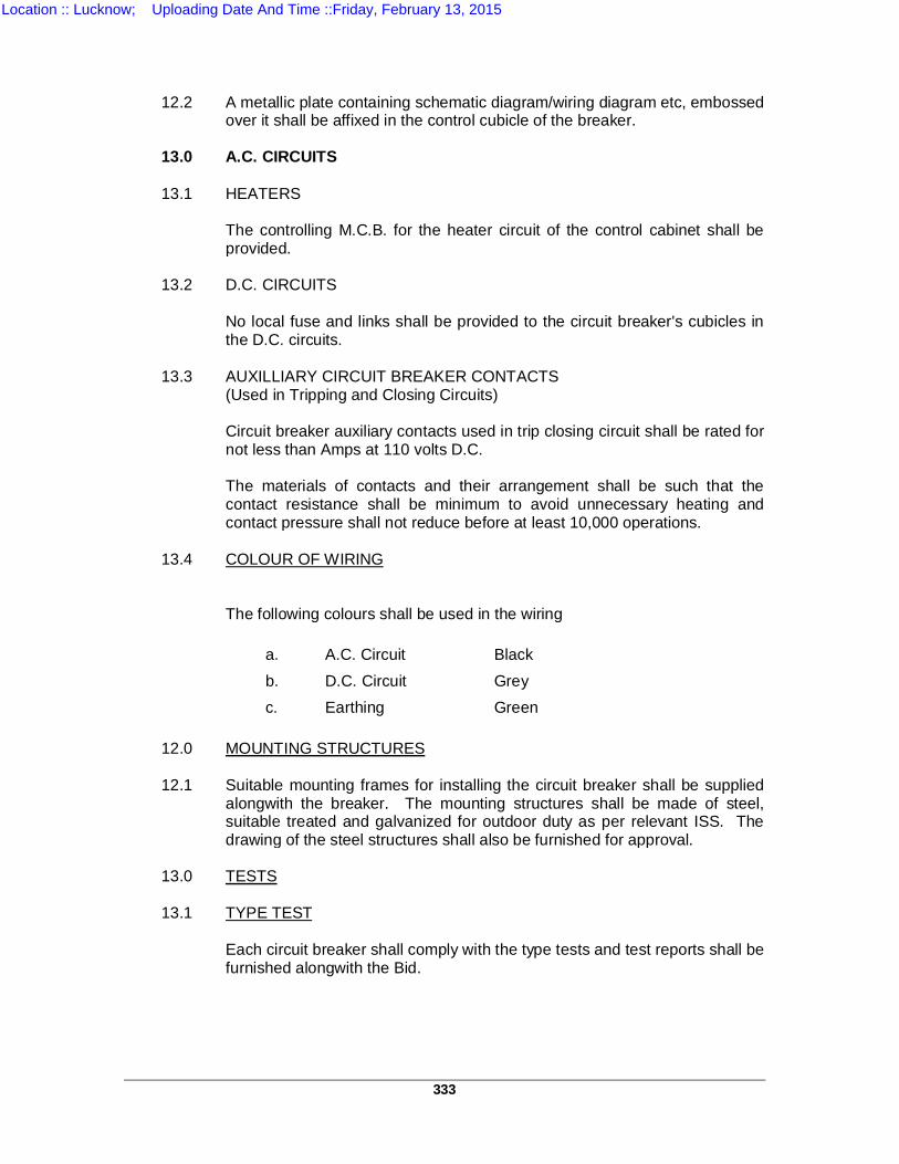
333
12.2
A metallic plate containing schematic diagram/wiring diagram etc, embossed over it shall be affixed in the control cubicle of the breaker.
13.0 A.C. CIRCUITS 13.1 HEATERS The controlling M.C.B. for the heater circuit of the control cabinet shall be
provided. 13.2 D.C. CIRCUITS No local fuse and links shall be provided to the circuit breaker's cubicles in
the D.C. circuits. 13.3 AUXILLIARY CIRCUIT BREAKER CONTACTS (Used in Tripping and Closing Circuits) Circuit breaker auxiliary contacts used in trip closing circuit shall be rated for
not less than Amps at 110 volts D.C. The materials of contacts and their arrangement shall be such that the
contact resistance shall be minimum to avoid unnecessary heating and contact pressure shall not reduce before at least 10,000 operations.
13.4
COLOUR OF WIRING
The following colours shall be used in the wiring a. A.C. Circuit Black b. D.C. Circuit Grey c. Earthing Green 12.0 MOUNTING STRUCTURES 12.1
Suitable mounting frames for installing the circuit breaker shall be supplied alongwith the breaker. The mounting structures shall be made of steel, suitable treated and galvanized for outdoor duty as per relevant ISS. The drawing of the steel structures shall also be furnished for approval.
13.0 TESTS 13.1 TYPE TEST Each circuit breaker shall comply with the type tests and test reports shall be
furnished alongwith the Bid.
Location :: Lucknow; Uploading Date And Time ::Friday, February 13, 2015
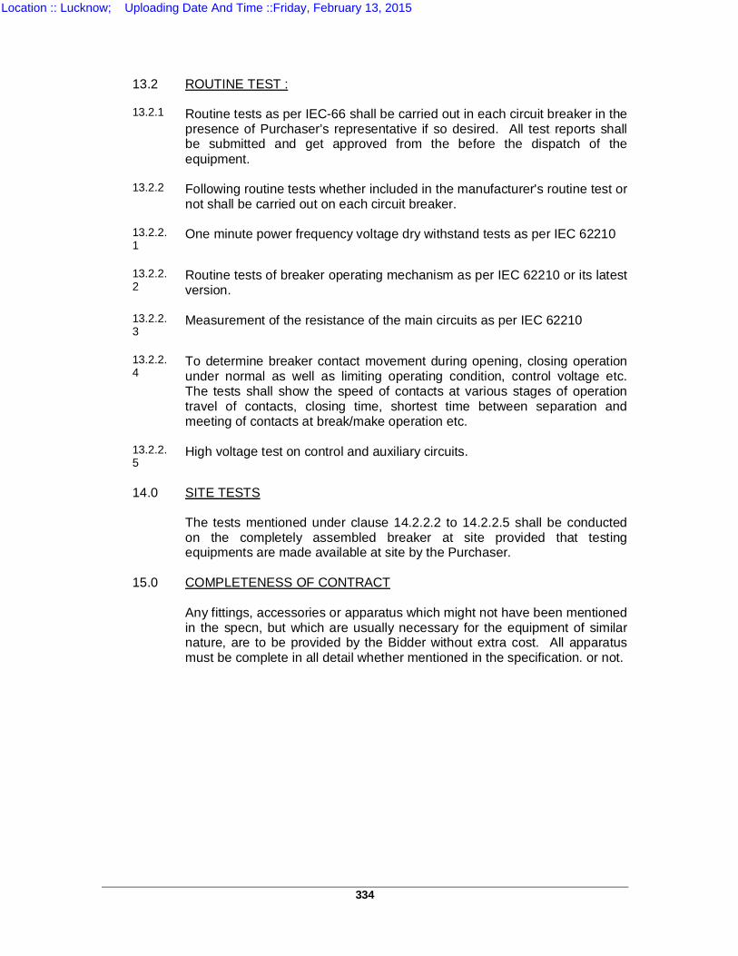
334
13.2 ROUTINE TEST : 13.2.1
Routine tests as per IEC-66 shall be carried out in each circuit breaker in the presence of Purchaser’s representative if so desired. All test reports shall be submitted and get approved from the before the dispatch of the equipment.
13.2.2
Following routine tests whether included in the manufacturer's routine test or not shall be carried out on each circuit breaker.
13.2.2.1
One minute power frequency voltage dry withstand tests as per IEC 62210
13.2.2.2
Routine tests of breaker operating mechanism as per IEC 62210 or its latest version.
13.2.2.3
Measurement of the resistance of the main circuits as per IEC 62210
13.2.2.4
To determine breaker contact movement during opening, closing operation under normal as well as limiting operating condition, control voltage etc. The tests shall show the speed of contacts at various stages of operation travel of contacts, closing time, shortest time between separation and meeting of contacts at break/make operation etc.
13.2.2.5
High voltage test on control and auxiliary circuits.
14.0 SITE TESTS The tests mentioned under clause 14.2.2.2 to 14.2.2.5 shall be conducted
on the completely assembled breaker at site provided that testing equipments are made available at site by the Purchaser.
15.0 COMPLETENESS OF CONTRACT Any fittings, accessories or apparatus which might not have been mentioned
in the specn, but which are usually necessary for the equipment of similar nature, are to be provided by the Bidder without extra cost. All apparatus must be complete in all detail whether mentioned in the specification. or not.
Location :: Lucknow; Uploading Date And Time ::Friday, February 13, 2015

335
TS - 3
TECHNICAL SPECIFICATION OF
145KV/36KV CURRENT TRANSFORMERS
1.0 STANDARDS:
1.1 Except as modified in this specification, the Current Transformers and accessories shall be in accordance with the latest editions of the following standards:-
1. IEC Publication 185 : Current Transformers
2. Draft Supplement to IEC publication 185 (1966)
: CTs for protection system for which transient performance is significant.
3. IS:2705 (Part-I to IV) 1991 & IEC 60444-1
: Specification for CTs.
4. IS : 2099 : High voltage porcelain bushing. 5. IS : 3347 : Dimension for porcelain T/F
6. IEC : 60-1973 : High voltage test techniques. 7. IS : 335 : Insulating oil for T/F and switchgear. 8. IS : 3202 : Code of practice: climate proofing of
electrical equipment.
9. IEC-270-1968 : Partial discharge measure-ment. 10. IEC-44(4)-1980 : Instrument transformers
measurement of partial discharge.
11. UPPTCL prevalent practices & operational experiences.
1.2 TYPE & RATING :
Location :: Lucknow; Uploading Date And Time ::Friday, February 13, 2015
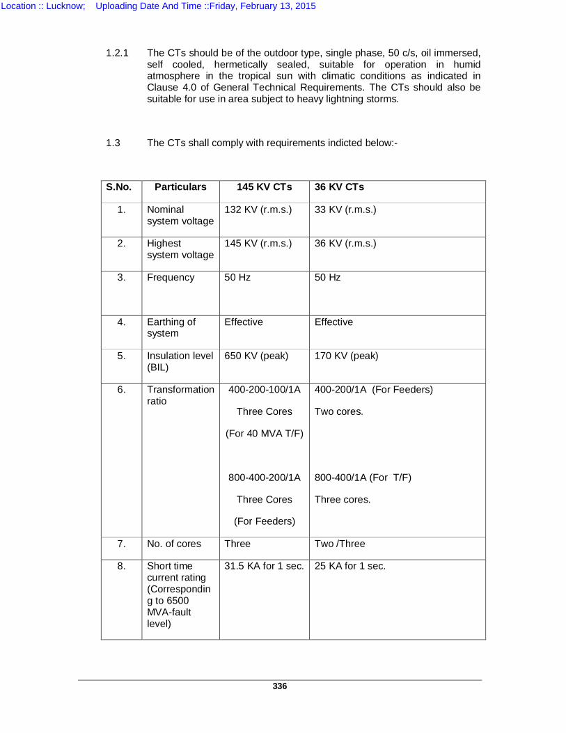
336
1.2.1 The CTs should be of the outdoor type, single phase, 50 c/s, oil immersed,
self cooled, hermetically sealed, suitable for operation in humid atmosphere in the tropical sun with climatic conditions as indicated in Clause 4.0 of General Technical Requirements. The CTs should also be suitable for use in area subject to heavy lightning storms.
1.3 The CTs shall comply with requirements indicted below:-
S.No. Particulars 145 KV CTs 36 KV CTs
1. Nominal system voltage
132 KV (r.m.s.) 33 KV (r.m.s.)
2. Highest system voltage
145 KV (r.m.s.) 36 KV (r.m.s.)
3. Frequency 50 Hz
50 Hz
4. Earthing of system
Effective Effective
5. Insulation level (BIL)
650 KV (peak) 170 KV (peak)
6. Transformation ratio
400-200-100/1A
Three Cores
(For 40 MVA T/F)
800-400-200/1A
Three Cores
(For Feeders)
400-200/1A (For Feeders)
Two cores.
800-400/1A (For T/F)
Three cores.
7. No. of cores Three Two /Three
8. Short time current rating (Corresponding to 6500 MVA-fault level)
31.5 KA for 1 sec. 25 KA for 1 sec.
Location :: Lucknow; Uploading Date And Time ::Friday, February 13, 2015
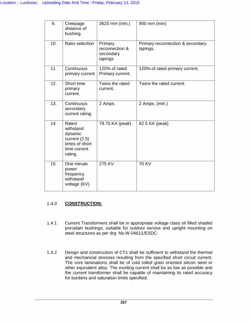
337
9. Creepage
distance of bushing.
3625 mm (min.)
900 mm (min)
10. Ratio selection Primary reconnection & secondary tapings
Primary reconnection & secondary tapings.
11. Continuous primary current
120% of rated Primary current.
120% of rated primary current.
12. Short time primary current.
Twice the rated current.
Twice the rated current.
13. Continuous secondary current rating.
2 Amps. 2 Amps. (min.)
14. Rated withstand dynamic current (2.5) times of short time current rating.
78.75 KA (peak) 62.5 KA (peak)
15. One minute power frequency withstand voltage (KV)
275 KV 70 KV
1.4.0 CONSTRUCTION:
1.4.1 Current Transformers shall be in appropriate voltage class oil filled shaded porcelain bushings, suitable for outdoor service and upright mounting on steel structures as per drg. No.W-04611/ESDC.
1.4.2 Design and construction of CTs shall be sufficient to withstand the thermal and mechanical stresses resulting from the specified short circuit current. The core laminations shall be of cold rolled grain oriented silicon steel or other equivalent alloy. The exciting current shall be as low as possible and the current transformer shall be capable of maintaining its rated accuracy for burdens and saturation limits specified.
Location :: Lucknow; Uploading Date And Time ::Friday, February 13, 2015
338
1.4.3 Current Transformers shall be suitable for outdoor use. Bidders should
quote, clearly specifying the type of CT design.
1.4.4 Current Transformers shall have high accuracy commensurate with the faster protection schemes employed in the system. The cores to be used for protection shall, therefore, besides being of low reactance type, produce undistorted secondary currents under transient condition on all the ratios.
1.4.5 CT secondary terminals shall be brought out in a weather proof terminal box. The terminal box shall be provided with five glands suitable for 1100 V grade, PVC insulated, PVC sheathed, 2x2.5 mm2 copper conductor cables.
1.4.6 Polarity marks shall be indelibly marked on each current transformer and at the lead terminations in the associated terminal block. Facility shall be provided for short circuiting and grounding the CT secondary at the terminal blocks.
1.4.7 CT shall be provided with name plate showing the particulars and diagram of the current transformer in line with the relevant IEC.
1.4.8 CTs shall be hermetically sealed to eliminate breathing and prevent air and moisture from entering the tank. These shall be provided with oil level gauge and pressure relieving device capable of releasing abnormal pressure.
1.4.9 Continuous current rating of secondary winding of core should be as per requirement specified. The secondary terminal should be brought out in a compartment on one side of CT for easy access. The secondary terminals should be provided with short circuiting arrangement. The secondary leads should be adequately reinforced to withstand normal handling without damage. The sealing arrangement of secondary terminals should also be provided in a compartment of two sides of CT terminal box.
The secondary terminal box should be partitioned so as to house the metering terminals separately with the provision of sealing and locking of the metering terminals.
Location :: Lucknow; Uploading Date And Time ::Friday, February 13, 2015
339
1.4.10 CT cores used for protective relaying purpose should be of accuracy class
specified. Magnetization curves should be furnished for metering and protection cores.
1.4.11 The secondary terminal box and junction box should be partitioned in two compartments comprising two hinged doors so as to house the metering & metering terminals separately with locking and sealing arrangement. “METERING” & “PROTECTION” should be clearly indicated on each compartment door respectively by engraving or by providing the metallic plate.
1.5.0 BUSHINGS :
1.5.1 Bushings shall be made of homogeneous, vitreous porcelain of high mechanical and dielectric strength. Glazing of porcelain shall be of uniform brown or dark brown colour with a smooth surface arranged to shed away rain water.
1.5.2 Bushings conforming to IS-2099 & 3347 shall be hollow porcelain type hermetically sealed to prevent ingress of moisture and with suitable facility to indicate oil level.
1.5.3 Cast metal end caps for the bushings shall be of high strength, hot dip galvanised malleable iron. They shall have smooth surface to prevent discharge taking place between the metal parts and porcelain as a result of ionisation.
1.6.0 TERMINAL CONNECTORS
1.6.1 All instruments transformers shall be provided with terminal connectors suitable to receive ACSR ZEBRA/PANTHER conductor in case of 145 KV CTs & ACSR Twin PANTHER conductor in case of 36 KV CTs as per Cl 4.02 of “Technical Specifications for Handling Erection Testing & Commissioning”.
1.6.2 Two grounding terminals shall be provided on the tank of each transformer on opposite sides. The grounding conductor shall be of MS flat of size 75x10 mm.
Location :: Lucknow; Uploading Date And Time ::Friday, February 13, 2015
340
1.6.3 MATERIAL:
For non-current carrying parts, the bolts, nuts, washer and check nuts up to 10 mm size should be of stainless steel and 12 mm size or above should be hot dip galvanized marked with ISI certification mark. Nuts, washers, bolt for current carrying parts should be tinned copper. These should be manufactured by a reputed concern and conform to IS-1363-1967 and IS-1367-1967 or latest amendment thereof
1.6.4 DESIGN:
The design of the connectors shall be such as to give intimate contact between the conductor and terminal and offer protection to the contact surfaces against effects of electrolytic (between two dissimilar metals) and atmospheric corrosion. The connector shall have sufficient mechanical strength and shall completely enclose the conductor and terminals. The connector shall hold the conductor and terminal very tightly so that the connector withstands the mechanical stresses set up by vibration, wind and short circuit current. The conductivity of connectors shall be high to minimize power loss. The connector should be designed with large factor of safety and should comply in all respect of temperature rise; resistance and tensile strength withstand capacity as per ISS-5561-1970 or amendment thereof.
1.7.0 GENERAL:
1.7.1 Instrument transformer shall be provided with suitable lifting arrangement to lift the bushings and the tank.
1.7.2 INSULATING OIL:
A sufficient quantity of oil for the base top and porcelain housing shall be furnished with each CT. Insulating oil shall meet requirements of IS-335 for use in electrical apparatus. The Bidder shall submit 4 sets of test reports of oil being filled in CT covering in all the tests specified in IS besides giving complete dissolved gas analysis of oil prior to filling. This test report shall be based on the basis of previous job executed by the bidder or on the prototype.
Location :: Lucknow; Uploading Date And Time ::Friday, February 13, 2015
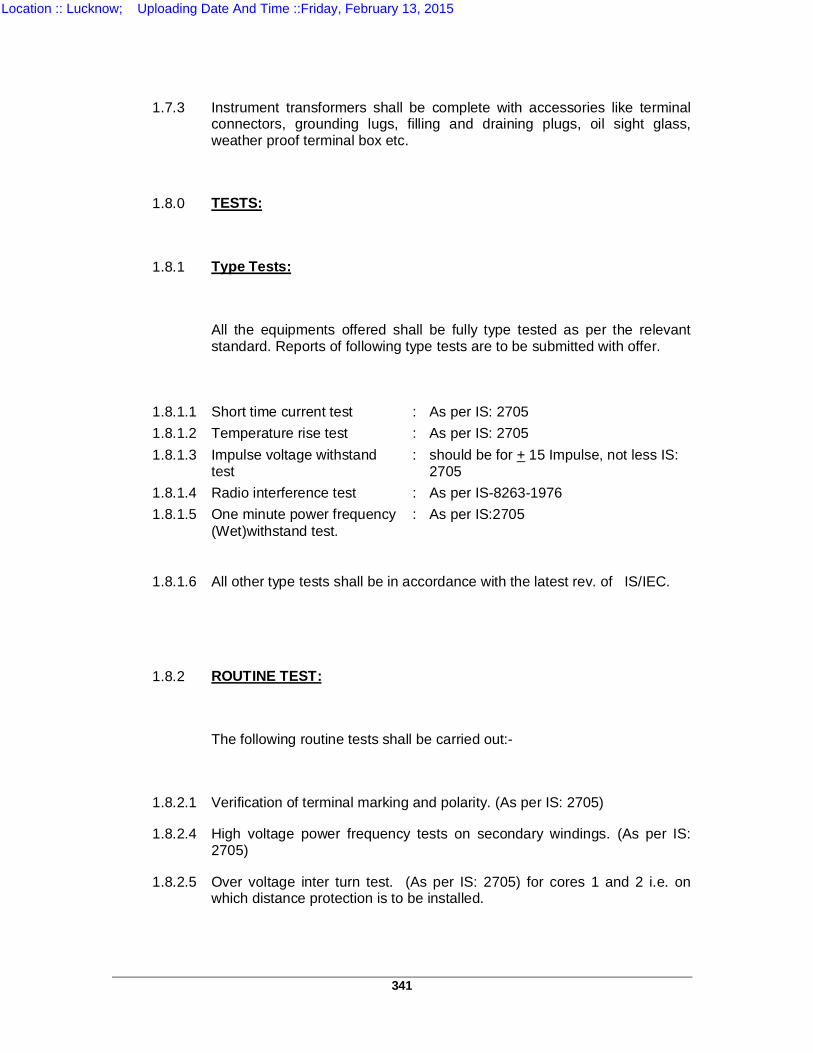
341
1.7.3 Instrument transformers shall be complete with accessories like terminal connectors, grounding lugs, filling and draining plugs, oil sight glass, weather proof terminal box etc.
1.8.0 TESTS:
1.8.1 Type Tests:
All the equipments offered shall be fully type tested as per the relevant standard. Reports of following type tests are to be submitted with offer.
1.8.1.1 Short time current test : As per IS: 2705 1.8.1.2 Temperature rise test : As per IS: 2705 1.8.1.3 Impulse voltage withstand
test : should be for + 15 Impulse, not less IS:
2705 1.8.1.4 Radio interference test : As per IS-8263-1976 1.8.1.5 One minute power frequency
(Wet)withstand test. : As per IS:2705
1.8.1.6 All other type tests shall be in accordance with the latest rev. of IS/IEC.
1.8.2 ROUTINE TEST:
The following routine tests shall be carried out:-
1.8.2.1 Verification of terminal marking and polarity. (As per IS: 2705)
1.8.2.4 High voltage power frequency tests on secondary windings. (As per IS: 2705)
1.8.2.5 Over voltage inter turn test. (As per IS: 2705) for cores 1 and 2 i.e. on which distance protection is to be installed.
Location :: Lucknow; Uploading Date And Time ::Friday, February 13, 2015
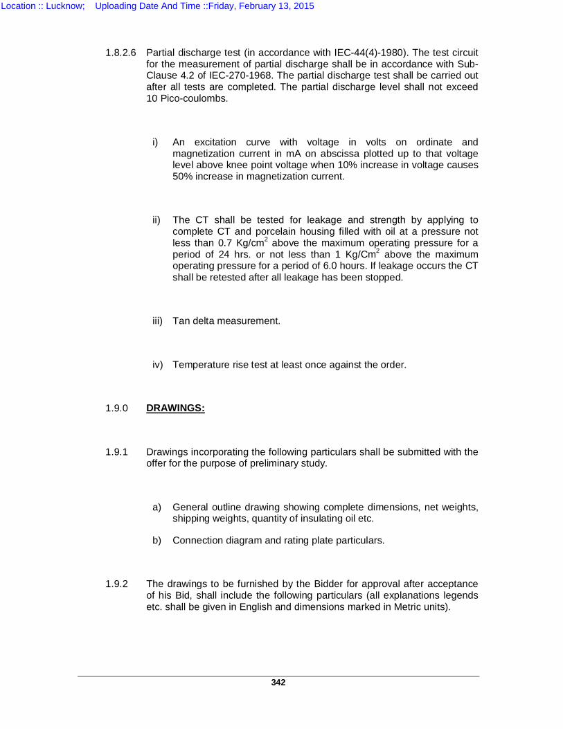
342
1.8.2.6 Partial discharge test (in accordance with IEC-44(4)-1980). The test circuit
for the measurement of partial discharge shall be in accordance with Sub-Clause 4.2 of IEC-270-1968. The partial discharge test shall be carried out after all tests are completed. The partial discharge level shall not exceed 10 Pico-coulombs.
i) An excitation curve with voltage in volts on ordinate and magnetization current in mA on abscissa plotted up to that voltage level above knee point voltage when 10% increase in voltage causes 50% increase in magnetization current.
ii) The CT shall be tested for leakage and strength by applying to complete CT and porcelain housing filled with oil at a pressure not less than 0.7 Kg/cm2 above the maximum operating pressure for a period of 24 hrs. or not less than 1 Kg/Cm2 above the maximum operating pressure for a period of 6.0 hours. If leakage occurs the CT shall be retested after all leakage has been stopped.
iii) Tan delta measurement.
iv) Temperature rise test at least once against the order.
1.9.0 DRAWINGS:
1.9.1 Drawings incorporating the following particulars shall be submitted with the offer for the purpose of preliminary study.
a) General outline drawing showing complete dimensions, net weights, shipping weights, quantity of insulating oil etc.
b) Connection diagram and rating plate particulars.
1.9.2 The drawings to be furnished by the Bidder for approval after acceptance of his Bid, shall include the following particulars (all explanations legends etc. shall be given in English and dimensions marked in Metric units).
Location :: Lucknow; Uploading Date And Time ::Friday, February 13, 2015

343
a) General outline drawings showing front and side elevations, top and
bottom plan views, all accessories and external features, with complete detailed dimensions, net and shipping weights, size of lifting lugs, quantity of insulations oil etc.
b) Name plate drawings of terminal connectors showing material composition, permissible temperature rise, current carrying capacity etc.
1.10.0 JUNCTION BOX:
1.10.2 Junction Box: Type-I (For 145 kV CTs)
a) One junction box shall be provided for each set of three nos. single phase 145 kV CTs as per drawing shown in fig. 1(a). Each junction box shall be equipped as below:
b) Junction box shall be equipped with at least 38 nos. ELMEX/TOSHA make terminals with shorting links. These terminals shall be suitable to receive at least 2 cores of 2.5 sq.cm. copper conductor cable. These terminals should be suitable to withstand up to 5 kV. Terminal blocks shall be provided with serial no. tags from 1 to 38.
All other provisions shall be the same as mentioned in para 1.10.1 c) to i)
1.10.3 Junction Box: Type-II (For 36 kV CTs)
a) For the outgoing 33 kV feeders one junction box shall be provided for three nos. single phase 36 kV CTs as per drawing shown in fig. 1(b). Each junction box shall be equipped as below:
Location :: Lucknow; Uploading Date And Time ::Friday, February 13, 2015
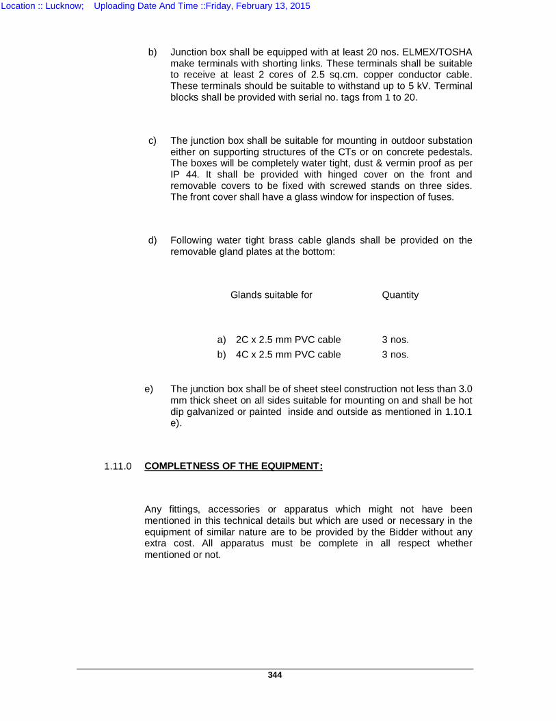
344
b) Junction box shall be equipped with at least 20 nos. ELMEX/TOSHA
make terminals with shorting links. These terminals shall be suitable to receive at least 2 cores of 2.5 sq.cm. copper conductor cable. These terminals should be suitable to withstand up to 5 kV. Terminal blocks shall be provided with serial no. tags from 1 to 20.
c) The junction box shall be suitable for mounting in outdoor substation either on supporting structures of the CTs or on concrete pedestals. The boxes will be completely water tight, dust & vermin proof as per IP 44. It shall be provided with hinged cover on the front and removable covers to be fixed with screwed stands on three sides. The front cover shall have a glass window for inspection of fuses.
d) Following water tight brass cable glands shall be provided on the removable gland plates at the bottom:
Glands suitable for Quantity
a) 2C x 2.5 mm PVC cable 3 nos. b) 4C x 2.5 mm PVC cable 3 nos.
e) The junction box shall be of sheet steel construction not less than 3.0 mm thick sheet on all sides suitable for mounting on and shall be hot dip galvanized or painted inside and outside as mentioned in 1.10.1 e).
1.11.0 COMPLETNESS OF THE EQUIPMENT:
Any fittings, accessories or apparatus which might not have been mentioned in this technical details but which are used or necessary in the equipment of similar nature are to be provided by the Bidder without any extra cost. All apparatus must be complete in all respect whether mentioned or not.
Location :: Lucknow; Uploading Date And Time ::Friday, February 13, 2015
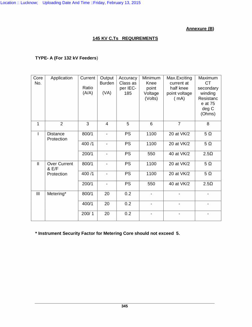
345
Annexure (B)
145 KV C.Ts REQUIREMENTS
TYPE- A (For 132 kV Feeders)
Core No.
Application Current
Ratio (A/A)
Output Burden
(VA)
Accuracy Class as per IEC-
185
Minimum Knee point
Voltage (Volts)
Max.Exciting current at half knee
point voltage ( mA)
Maximum CT
secondary winding
Resistance at 75 deg C
(Ohms)
1 2 3 4 5 6 7 8
I Distance Protection
800/1 - PS 1100 20 at VK/2 5 Ω
400 /1 - PS 1100 20 at VK/2 5 Ω
200/1 - PS 550 40 at VK/2 2.5Ω
II Over Current & E/F Protection
800/1 - PS 1100 20 at VK/2 5 Ω
400 /1 - PS 1100 20 at VK/2 5 Ω
200/1 - PS 550 40 at VK/2 2.5Ω
III
Metering* 800/1 20 0.2 - - -
400/1 20 0.2 - - -
200/ 1 20 0.2 - - -
* Instrument Security Factor for Metering Core should not exceed 5.
Location :: Lucknow; Uploading Date And Time ::Friday, February 13, 2015
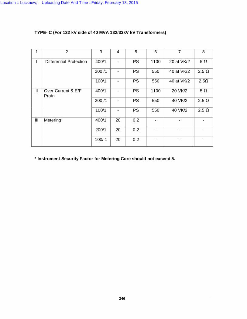
346
TYPE- C (For 132 kV side of 40 MVA 132/33kV kV Transformers)
1 2 3 4 5 6 7 8
I Differential Protection 400/1 - PS 1100 20 at VK/2 5 Ω
200 /1 - PS 550 40 at VK/2 2.5 Ω
100/1 - PS 550 40 at VK/2 2.5Ω
II Over Current & E/F Protn.
400/1 - PS 1100 20 VK/2 5 Ω
200 /1 - PS 550 40 VK/2 2.5 Ω
100/1 - PS 550 40 VK/2 2.5 Ω
III
Metering* 400/1 20 0.2 - - -
200/1 20 0.2 - - -
100/ 1 20 0.2 - - -
* Instrument Security Factor for Metering Core should not exceed 5.
Location :: Lucknow; Uploading Date And Time ::Friday, February 13, 2015
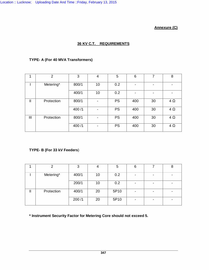
347
Annexure (C)
36 KV C.T. REQUIREMENTS
TYPE- A (For 40 MVA Transformers)
1 2 3 4 5 6 7 8
I
Metering* 800/1 10 0.2 - - -
400/1 10 0.2 - - -
II Protection 800/1 - PS 400 30 4 Ω
400 /1 - PS 400 30 4 Ω
III Protection 800/1 - PS 400 30 4 Ω
400 /1 - PS 400 30 4 Ω
TYPE- B (For 33 kV Feeders)
1 2 3 4 5 6 7 8
I
Metering* 400/1 10 0.2 - - -
200/1 10 0.2 - - -
II Protection 400/1 20 5P10 - - -
200 /1 20 5P10 - - -
* Instrument Security Factor for Metering Core should not exceed 5.
Location :: Lucknow; Uploading Date And Time ::Friday, February 13, 2015
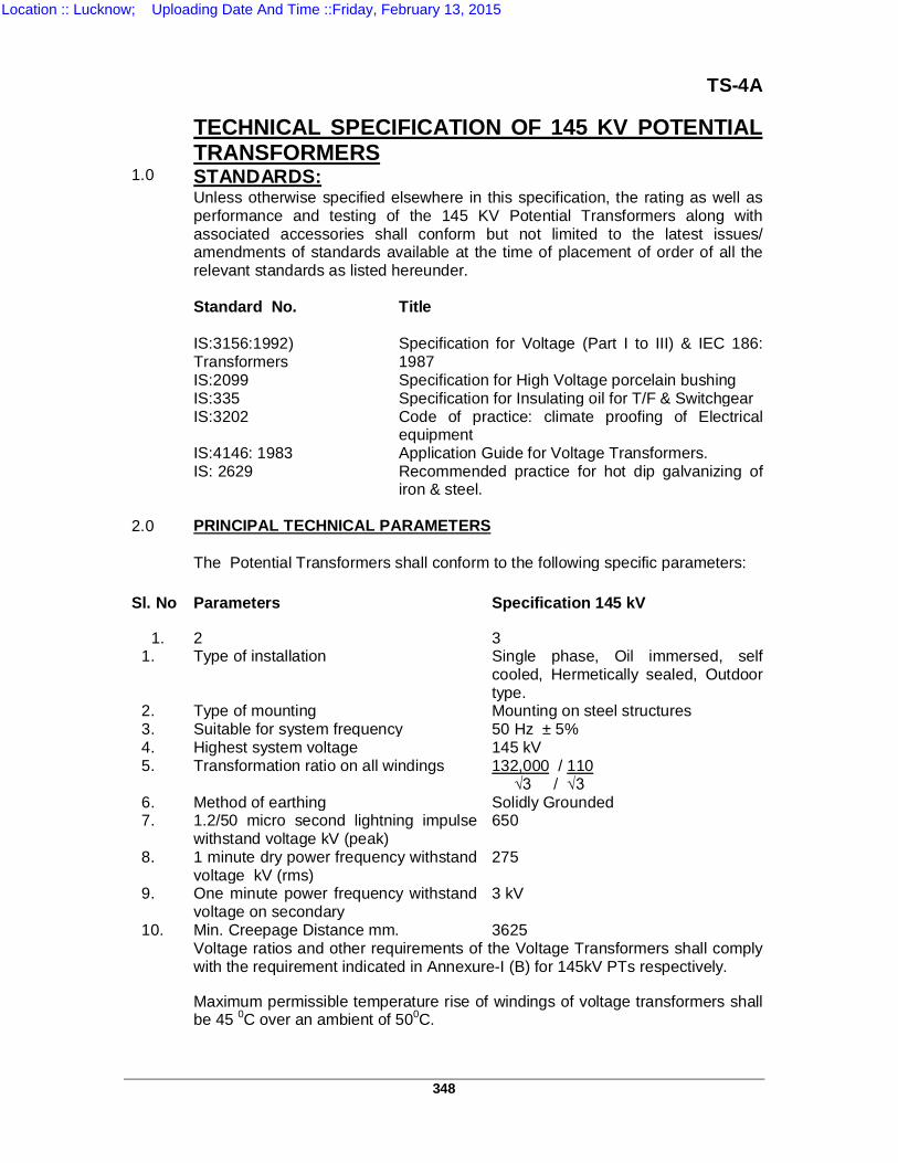
348
TS-4A TECHNICAL SPECIFICATION OF 145 KV POTENTIAL
TRANSFORMERS 1.0 STANDARDS: Unless otherwise specified elsewhere in this specification, the rating as well as
performance and testing of the 145 KV Potential Transformers along with associated accessories shall conform but not limited to the latest issues/ amendments of standards available at the time of placement of order of all the relevant standards as listed hereunder.
Standard No. Title IS:3156:1992)
Transformers Specification for Voltage (Part I to III) & IEC 186: 1987
IS:2099 Specification for High Voltage porcelain bushing IS:335 Specification for Insulating oil for T/F & Switchgear IS:3202 Code of practice: climate proofing of Electrical
equipment IS:4146: 1983 Application Guide for Voltage Transformers. IS: 2629 Recommended practice for hot dip galvanizing of
iron & steel. 2.0 PRINCIPAL TECHNICAL PARAMETERS
The Potential Transformers shall conform to the following specific parameters:
Sl. No Parameters Specification 145 kV
1. 2 3 1. Type of installation Single phase, Oil immersed, self
cooled, Hermetically sealed, Outdoor type.
2. Type of mounting Mounting on steel structures 3. Suitable for system frequency 50 Hz ± 5% 4. Highest system voltage 145 kV 5. Transformation ratio on all windings 132,000 / 110
√3 / √3 6. Method of earthing Solidly Grounded 7. 1.2/50 micro second lightning impulse
withstand voltage kV (peak) 650
8. 1 minute dry power frequency withstand voltage kV (rms)
275
9. One minute power frequency withstand voltage on secondary
3 kV
10. Min. Creepage Distance mm. 3625 Voltage ratios and other requirements of the Voltage Transformers shall comply
with the requirement indicated in Annexure-I (B) for 145kV PTs respectively.
Maximum permissible temperature rise of windings of voltage transformers shall be 45 0C over an ambient of 500C.
Location :: Lucknow; Uploading Date And Time ::Friday, February 13, 2015
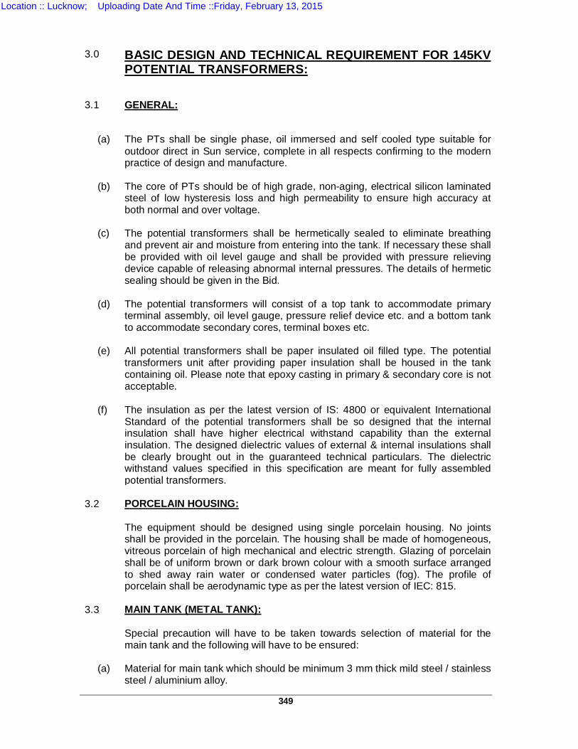
349
3.0 BASIC DESIGN AND TECHNICAL REQUIREMENT FOR 145KV
POTENTIAL TRANSFORMERS:
3.1 GENERAL:
(a) The PTs shall be single phase, oil immersed and self cooled type suitable for
outdoor direct in Sun service, complete in all respects confirming to the modern practice of design and manufacture.
(b) The core of PTs should be of high grade, non-aging, electrical silicon laminated
steel of low hysteresis loss and high permeability to ensure high accuracy at both normal and over voltage.
(c) The potential transformers shall be hermetically sealed to eliminate breathing
and prevent air and moisture from entering into the tank. If necessary these shall be provided with oil level gauge and shall be provided with pressure relieving device capable of releasing abnormal internal pressures. The details of hermetic sealing should be given in the Bid.
(d) The potential transformers will consist of a top tank to accommodate primary
terminal assembly, oil level gauge, pressure relief device etc. and a bottom tank to accommodate secondary cores, terminal boxes etc.
(e) All potential transformers shall be paper insulated oil filled type. The potential
transformers unit after providing paper insulation shall be housed in the tank containing oil. Please note that epoxy casting in primary & secondary core is not acceptable.
(f) The insulation as per the latest version of IS: 4800 or equivalent International
Standard of the potential transformers shall be so designed that the internal insulation shall have higher electrical withstand capability than the external insulation. The designed dielectric values of external & internal insulations shall be clearly brought out in the guaranteed technical particulars. The dielectric withstand values specified in this specification are meant for fully assembled potential transformers.
3.2 PORCELAIN HOUSING: The equipment should be designed using single porcelain housing. No joints
shall be provided in the porcelain. The housing shall be made of homogeneous, vitreous porcelain of high mechanical and electric strength. Glazing of porcelain shall be of uniform brown or dark brown colour with a smooth surface arranged to shed away rain water or condensed water particles (fog). The profile of porcelain shall be aerodynamic type as per the latest version of IEC: 815.
3.3 MAIN TANK (METAL TANK):
Special precaution will have to be taken towards selection of material for the main tank and the following will have to be ensured:
(a) Material for main tank which should be minimum 3 mm thick mild steel / stainless
steel / aluminium alloy.
Location :: Lucknow; Uploading Date And Time ::Friday, February 13, 2015
350
(b) The practice of providing inserts of non-magnetic material in the body of the tank with suitable welding to reduce eddy current shall not be acceptable. This problem should be avoided by selection of tank of suitable material.
(c) Welded joints have to be minimized to avoid possibility of oil leakage. In any
case welding in horizontal plane shall be avoided. The material selected for the tank shall be justified with suitable explanation.
(d) The slot / hole cutting in the bottom tank should be done smoothly to avoid any
sharp edges within the tank. All welded surfaces need to be smoothening and shall be covered with pressboard or other insulating material of good mechanical properties.
(e) The bottom tank should not have any dents and pitting to ensure proper
tightening of gasket and to avoid any oil leakage. Fabrication of bottom tank shall be done by utilizing fresh sheet steel only.
(f) The top & bottom tanks should be painted with two coats of zinc chromate primer
both inside and outside after proper cleaning and pickling. Finally the inside of tanks should be painted with two coats of white enameled paint or any other paint which is non-reactive to oil.
4.0 WINDINGS: 4.1 PRIMARY WINDING: All primaries of PTs shall be connected in phase to neutral with the neutral
solidly earthed. The neutral of the system is also solidly earthed. 4.2 SECONDARY WINDINGS: All PTs shall be provided with 3 separate secondary windings each rated for110 /
√3 volts for connection in star and delta separately. The star winding to be used for metering, relaying (distance relays) and synchronizing should be of accuracy class specified. The rated burden of all 3 windings shall not be less than the specified VA burden. The secondary of the PTs should be capable of simultaneous loading at their individual rated capacities.
The secondary terminal box should be partitioned so as to house the
metering terminals separately with locking and sealing arrangement of metering terminals. “METERING” & “PROTECTION” should be clearly indicated on each compartment door respectively by engraving or by providing the metallic plate.
5.0 INSULATION: The equipment shall withstand satisfactorily dielectric voltage corresponding to
basic insulation level of 650 KV. 6.0 TEMPERATURE RISE: The PTs shall be designed to limit the temperature of windings and other parts
as specified in the Indian Standard but owing the maximum ambient temperature being 50C instead of 40C. The corresponding temperature rise should be reduced by 10C as specified in 7.2.1.2 of IS: 3156 (Part-I) 1992.
Location :: Lucknow; Uploading Date And Time ::Friday, February 13, 2015
351
The maximum attainable temperature of the windings cores etc. therefore, shall
not exceed 90C while the maximum temperature of oil at the top should be limited to 85C. The temperature rise at 1.2 times rated primary voltage when applied continuously at rated frequency and simultaneous rated burden on both the secondaries shall not exceed the above specified limits and the temperature rise at 1.5 times rated voltage when applied for 30 seconds starting from previous stable operating condition at rated frequency and simultaneous rated burden on both secondaries should not exceed the above temperature limits by more than 10C.
7.0 INSULATING OIL: The quantity of insulating oil in each transformer and complete specifications of
the oil shall be stated in the Bid. The oil shall confirm to the requirements of IS: 335. The PTs shall be supplied completely filled with oil. The supplier shall submit the test reports of oil being filled in PTs covering in all the tests specified in IS besides giving complete dissolved gas analysis of oil prior to filling.
8.0 TYPE OF MOUNTING: The PTs shall be suitable for mounting on steel structures as per drawing
enclosed with specification. Foundation details of the equipment must invariably match the provisions as shown in the above drawing. The necessary flanges, bolts etc. for the base of the PTs shall be supplied and these shall be hot-dip galvanized.
9.0 TERMINAL CONNECTORS: Bi-metallic terminal connectors for connecting "ACSR Panther" conductor to the
PT terminals must be supplied along with the PT. 9.1 MATERIAL: All the steel bolts, nuts, washers and checknuts shall be hot dip galvanized
marked with ISI certification mark. All steel bolts and nuts shall confirm to IS: 1363-1967 and IS: 1367-1961 or amendment thereof. Bolts and nuts should be manufactured by a reputed concern.
9.2 DESIGN: The design of the connectors shall be such as to give firm and full contact
between connector, the conductor and terminal and offer protection to the design of the connectors shall be such as to give firm and full contact surface against effects of electrolytic (between two dissimilar metals) and atmospheric corrosion. The connector shall have sufficient mechanical strength and shall completely enclose the conductor and terminal. The connector shall hold the conductor and terminal very tightly so that the connector withstands mechanical stresses setup by vibration, wind and short circuit current. The conductivity of connectors shall be high enough to minimize power loss.
The connectors shall be designed with large factor of safety and shall comply in all respects of temperature rise resistance and tensile strength withstand capacity as per IS: 5561-1970 or amendment thereof, as mentioned below:-
(a) TEMPERATURE RISE TEST: The temperature rise of terminal connectors above a reference ambient
temperature of 400C when carrying rated current shall not exceed 450C. If the ambient temperature exceeds 400C the permissible temperature rise shall be reduced by an amount equal to the excess ambient temperature. So with the ambient of 500C in our climatic conditions, the allowable maximum temperature rise is 350C only.
Location :: Lucknow; Uploading Date And Time ::Friday, February 13, 2015
352
(b) RESISTANCE TEST: The resistance of 1.25 m of a conductor including one terminal connector such
as splices or elbows shall not exceed the resistance of 1.25 m of the identical conductor without connector, by more than 10%.
(c) TENSILE TEST:
The test will be carried out in tensile testing machine and test load will be applied in direction of the conductor as below:
(i) A tensile load of about 5% of the breaking load of the conductor shall be applied
and the conductor shall be marked in such a way that movement relative to the conductor can easily be detected without any subsequent adjustment of terminal connector. The load shall be steadily increased to 10% of the breaking load. This load shall be maintained for 1 minute. There will be no movement of the conductor relative to the terminal connector due to slip during this1minute period and no failure of the connector will take place.
(ii) Connector shall have at least 4 nos. of bolts and these should be located as
close to the conductor as possible and should be opposite to each other. Bolt diameter should be such as to give desired clamping and contact pressure.
(iii) A check nut shall be provided on each bolt nut to avoid loosening nuts due to
vibration.
(iv) The contact surface shall be ground finished to the required diameter of the conductor. The edges of the connectors shall be adequately round so as to minimize the corona effect.
(v) All casting shall be free from blowholes, cracks & other casting defects.
(vi) All current carrying parts shall be designed and manufactured to have minimum
contact resistance.
10.0 IDENTIFICATION PLATES: 10.1 The Supplier is required to affix a plate on the PT inscribed with the following
information:- 1. Specification No. 2. Year of Order 3. Property of UPPTCL 11.0 RATING & DIAGRAM PLATE:
A non-corroding metal name plate shall be attached to each instrument
transformer and located in a conspicuous position clearly readable to a person standing on the ground. The name plate marking shall comply with IS and shall includes connection diagram.
The PT sealed at the factory, shall have this fact indicated on the name plate or
label if it is undesirable that oil samples be withdrawn periodically for test purposes. The fact that the instrument transformers should not be titled more than 30 degrees from the vertical or normal position during transportation or while in storage should be indicated on the name plate or label. Also appropriate instructions for handling and precautions to be exercised shall be indicated.
Location :: Lucknow; Uploading Date And Time ::Friday, February 13, 2015
353
12.0 PT JUNCTION BOX:
12.1 Junction boxes shall be adequately designed and dimensioned to accommodate the fuse links, miniature circuit breaker and various terminal connectors providing sufficient earth clearance, and should also have convenient space to house various cable glands.
12.2 The junction boxes should be of cast iron or fabricated construction. In the case of fabricated construction the gauge used should at least be 16 SWG and not less than this gauge. The junction boxes should be painted with one coat of Zinc Chromate primer and two coats of light Grey Enamel paint or any other approved paint both inside and outside after proper cleaning and phosphatising. These should be dust and vermin proof, water tight and suitable for mounting in outdoor substations either on supporting structures of the equipment or on concrete pedestals. Each junction box shall have slanting top and shall be provided with front hinged covers and with suitable water tight cable glands as per approved drawings. The cover and the flanges shall be provided with suitable packing and gaskets so as to make these junction boxes completely water tight. Blanking washers should be provided in the cable glands.
12.3 The terminal blocks provided with these junction boxes shall be rated for 15 Amps. and will be suitable for uninterrupted duty. The terminal blocks shall be400 volt grade complete with insulated barriers, terminal studs, washers, nuts and identification strips and shall have also disconnecting and shorting links. These should be suitable to receive at least 2 cores of 2.5 mm sq. copper conductor cables. The terminal blocks should preferably be made of Kirloskar-Asea type OTFA-46, Essan, Elmax make terminals or equivalent. The fuse links employed should be of high rupturing capacity non deteriorating, International Standard make mounted in such a fashion that these can be easily taken out and replaced without removing any wiring. The NS type fuse links should be provided with fuse carrier and base assembly such that visual indication of blown fuses may be possible from the inspection window without removing the cover of fuse fittings. Necessary internal connections between the terminal block and other apparatus such as fuses, miniature circuit breakers etc. are shown as in sketches enclosed.
12.4 The junction boxes should be as far as possible in accordance with sketches enclosed with the specification, however, it is at the discretion of the Bidder to alter the dimensions slightly to suit his designs. If any major alteration is required after approval of the drawings at the manufacturing stage, the same may be got approved by this office with specific reason thereof. The wiring should be provided as shown in the sketch.
12.5 The miniature Circuit Breakers should be single pole 5 Amps. , 110 V A.C. continuous rating having thermal over load protection LVPAS or MORARJI DORMAN or equivalent make and with one normally closed and one normally open set of auxiliary contacts and should confirm with the relevant ISS.
12.6 The junction Box should be partitioned in two compartments comprising two doors hinged in the middle so as to house the metering & protection terminals separately with locking & sealing arrangement. “METERING” & “PROTECTION” should be clearly indicated on each compartment door respectively by engraving or by providing the metallic plate.
Location :: Lucknow; Uploading Date And Time ::Friday, February 13, 2015
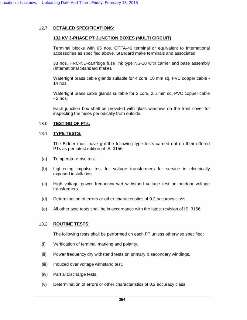
354
12.7 DETAILED SPECIFICATIONS: 132 KV 3-PHASE PT JUNCTION BOXES (MULTI CIRCUIT)
Terminal blocks with 65 nos. OTFA-46 terminal or equivalent to International accessories as specified above. Standard make terminals and associated 33 nos. HRC-ND-cartridge fuse link type NS-10 with carrier and base assembly (International Standard make). Watertight brass cable glands suitable for 4 core, 10 mm sq. PVC copper cable - 14 nos. Watertight brass cable glands suitable for 2 core, 2.5 mm sq. PVC copper cable - 2 nos. Each junction box shall be provided with glass windows on the front cover for inspecting the fuses periodically from outside.
13.0 TESTING OF PTs:
13.1 TYPE TESTS:
The Bidder must have got the following type tests carried out on their offered
PTs as per latest edition of IS: 3156:
(a) Temperature rise test.
(b) Lightening impulse test for voltage transformers for service in electrically exposed installation.
(c) High voltage power frequency wet withstand voltage test on outdoor voltage
transformers.
(d) Determination of errors or other characteristics of 0.2 accuracy class.
(e) All other type tests shall be in accordance with the latest revision of IS: 3156.
13.2 ROUTINE TESTS:
The following tests shall be performed on each PT unless otherwise specified:
(i) Verification of terminal marking and polarity. (ii) Power frequency dry withstand tests on primary & secondary windings. (iii) Induced over voltage withstand test. (iv) Partial discharge tests. (v) Determination of errors or other characteristics of 0.2 accuracy class.
Location :: Lucknow; Uploading Date And Time ::Friday, February 13, 2015
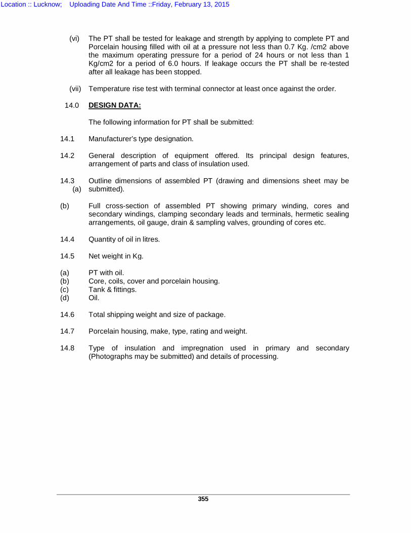
355
(vi) The PT shall be tested for leakage and strength by applying to complete PT and
Porcelain housing filled with oil at a pressure not less than 0.7 Kg. /cm2 above the maximum operating pressure for a period of 24 hours or not less than 1 Kg/cm2 for a period of 6.0 hours. If leakage occurs the PT shall be re-tested after all leakage has been stopped.
(vii) Temperature rise test with terminal connector at least once against the order.
14.0 DESIGN DATA:
The following information for PT shall be submitted: 14.1 Manufacturer’s type designation. 14.2 General description of equipment offered. Its principal design features,
arrangement of parts and class of insulation used. 14.3 (a)
Outline dimensions of assembled PT (drawing and dimensions sheet may be submitted).
(b) Full cross-section of assembled PT showing primary winding, cores and
secondary windings, clamping secondary leads and terminals, hermetic sealing arrangements, oil gauge, drain & sampling valves, grounding of cores etc.
14.4 Quantity of oil in litres. 14.5 Net weight in Kg. (a) PT with oil. (b) Core, coils, cover and porcelain housing. (c) Tank & fittings. (d) Oil. 14.6 Total shipping weight and size of package. 14.7 Porcelain housing, make, type, rating and weight. 14.8 Type of insulation and impregnation used in primary and secondary
(Photographs may be submitted) and details of processing.
Location :: Lucknow; Uploading Date And Time ::Friday, February 13, 2015
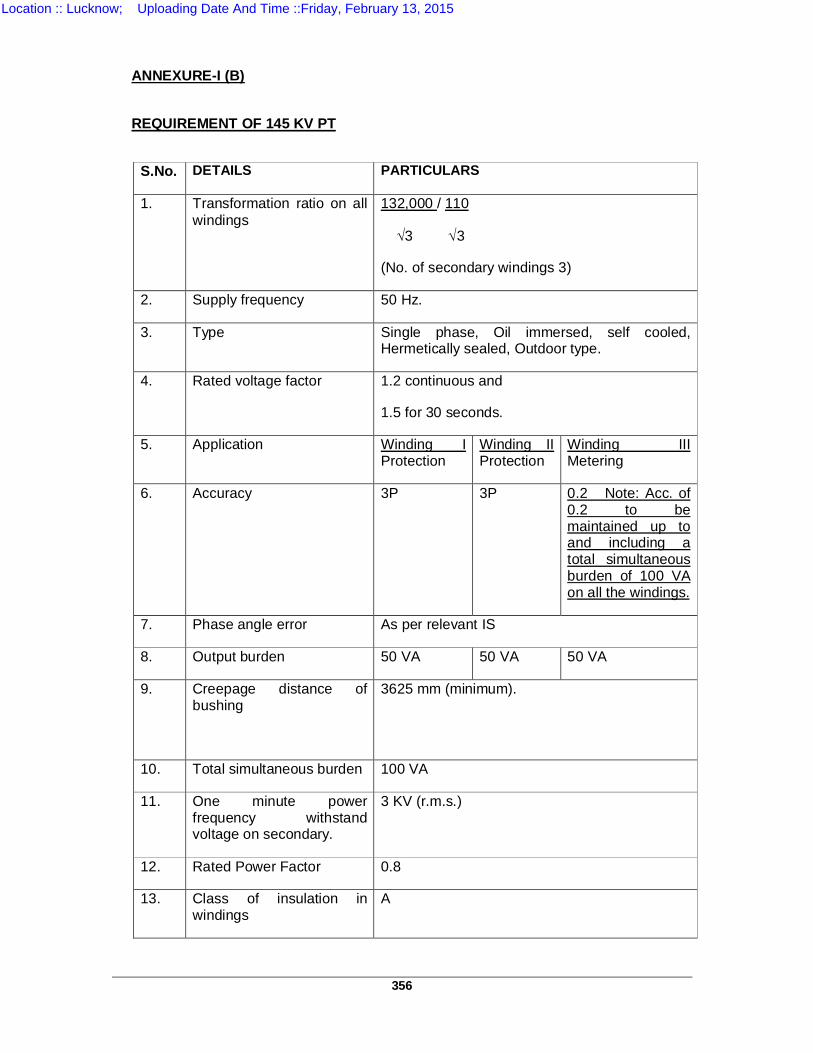
356
ANNEXURE-I (B) REQUIREMENT OF 145 KV PT
S.No. DETAILS PARTICULARS
1. Transformation ratio on all windings
132,000 / 110
3 3
(No. of secondary windings 3)
2. Supply frequency 50 Hz.
3. Type Single phase, Oil immersed, self cooled, Hermetically sealed, Outdoor type.
4. Rated voltage factor 1.2 continuous and
1.5 for 30 seconds.
5. Application Winding I Protection
Winding II Protection
Winding III Metering
6. Accuracy 3P 3P 0.2 Note: Acc. of 0.2 to be maintained up to and including a total simultaneous burden of 100 VA on all the windings.
7. Phase angle error As per relevant IS
8. Output burden 50 VA 50 VA 50 VA
9. Creepage distance of bushing
3625 mm (minimum).
10. Total simultaneous burden 100 VA
11. One minute power frequency withstand voltage on secondary.
3 KV (r.m.s.)
12. Rated Power Factor 0.8
13. Class of insulation in windings
A
Location :: Lucknow; Uploading Date And Time ::Friday, February 13, 2015
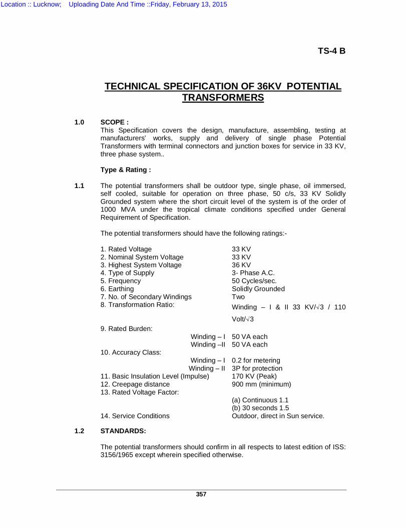
357
TS-4 B
TECHNICAL SPECIFICATION OF 36KV POTENTIAL TRANSFORMERS
1.0 SCOPE : This Specification covers the design, manufacture, assembling, testing at
manufacturers’ works, supply and delivery of single phase Potential Transformers with terminal connectors and junction boxes for service in 33 KV, three phase system..
Type & Rating : 1.1 The potential transformers shall be outdoor type, single phase, oil immersed,
self cooled, suitable for operation on three phase, 50 c/s, 33 KV Solidly Grounded system where the short circuit level of the system is of the order of 1000 MVA under the tropical climate conditions specified under General Requirement of Specification.
The potential transformers should have the following ratings:- 1. Rated Voltage 33 KV 2. Nominal System Voltage 33 KV 3. Highest System Voltage 36 KV 4. Type of Supply 3- Phase A.C. 5. Frequency 50 Cycles/sec. 6. Earthing Solidly Grounded 7. No. of Secondary Windings Two 8. Transformation Ratio: Winding – I & II 33 KV/√3 / 110
Volt/√3 9. Rated Burden: Winding – I 50 VA each Winding –II 50 VA each 10. Accuracy Class: Winding – I 0.2 for metering Winding – II 3P for protection 11. Basic Insulation Level (Impulse) 170 KV (Peak) 12. Creepage distance 900 mm (minimum) 13. Rated Voltage Factor: (a) Continuous 1.1 (b) 30 seconds 1.5 14. Service Conditions Outdoor, direct in Sun service. 1.2 STANDARDS: The potential transformers should confirm in all respects to latest edition of ISS:
3156/1965 except wherein specified otherwise.
Location :: Lucknow; Uploading Date And Time ::Friday, February 13, 2015
358
1.3 GENERAL:
(a) The PTs shall be single phase, oil immersed, self cooled type suitable for outdoor direct in Sun service complete in all respects confirming to the modern practice of design and manufacture.
(b) hysteresis loss and high permeability to ensure high accuracy at both normal
and over voltages. I The potential transformers should preferably be hermetically sealed to eliminate
breathing and prevent air and moisture from entering into the tank. If necessary these should be provided with oil level gauge and pressure relieving device capable of releasing abnormal internal pressures. The details of hermetic sealing should be given in the Bid.
1.4 WINDINGS:
(a) PRIMARY WINDING: All primaries of PTs should be connected in phase to neutral with the neutral
point solidly earthed. The neutral of the system is also solidly earthed.
(b) SECONDARY WINDINGS: All PTs shall be provided with two separate secondary windings each rated for
110 / √3 volts for connection in star and delta separately. The star connection is to be used for metering and shall be of accuracy class specified. The rated burden of this winding shall not be less than the values specified. The delta connection is to be used for protection relaying (directional relays) should be of accuracy class specified. The two secondary of the PTs should be capable of simultaneous loading at their individual rated capacities.
The secondary terminal box should be partitioned so as to house the
metering terminals separately with the provision of sealing & locking of the metering terminals. “METERING” & “PROTECTION” should be clearly indicated on each compartment cover respectively by engraving or by providing the metallic plate.
1.5 INSULATION: The potential transformers should withstand satisfactorily dielectric test voltage
corresponding to basic insulation level of 170 KV for 36 KV PTs. 1.6 TEMPERATURE RISE: The PTs should be designed to limit the temperature of windings and other parts
as specified in the Indian Standard but owing to maximum ambient temperature being 50oC, instead of 40oC specified in Note 1 of Table-3 of IS: 3156(Part-I) 1965 the corresponding temperature rise should be reduced by 10oC.
The maximum attainable temperature of the windings, cores etc. thereof should
not exceed 95oC while the maximum temperature of oil at the top should be limited to 85oC.
Location :: Lucknow; Uploading Date And Time ::Friday, February 13, 2015
359
The temperature rise at 1.1 times rated primary voltage when applied
continuously at rated frequency and simultaneous rated burden on both the secondaries shall not exceed the above specified limits and the temperature rise at 1.5 times rated voltage when applied for 30 seconds starting from previous stable operating condition at rated frequency and simultaneous rated burden on both secondaries should not exceed the above temperature limits by more than 10oC.
1.7 INSULATING OIL: The quantity of insulating oil in each transformer and complete specifications of
the oil should be stated in the Bid. The oil should confirm to the requirements of IS -335. The PTs shall be supplied completely filled with oil.
1.8 TYPE OF MOUNTING: The PTs shall be suitable for mounting on steel structures. The necessary
flanges, bolts etc. for the base of the PTs should be supplied and these should be hot-dip 359uthorized. 4 nos. mounting holes (15 mm) are required at rectangular spacing of 370x250 mm.
1.9 TERMINAL CONNECTORS: Bi-metallic terminal connectors suitable for connecting ACSR “Panther”
conductor to the PT terminals should be supplied. 1.9.1 MATERIAL: All the steel bolts and nuts, washers, checknuts should be hot dip 359uthorized
marked with ISI certification mark. Steel bolts and nuts shall confirm to IS: 1363-1967 and IS: 1367-1961 or amendment thereof. Bolts and nuts should be manufactured by a reputed concern.
1.9.2 DESIGN: The design of the connectors shall be such as to give intimate contact between
connector, the conductor and terminal and offer protection to the contact surface against effects of electrolytic (between two dissimilar metals) and atmospheric corrosion. The connector shall have sufficient mechanical strength and shall completely enclose the conductor and terminal. The connector shall hold the conductor and terminal very tightly so that the connector withstands mechanical stresses setup by vibration, wind and short circuit current. The conductivity of connectors shall be high enough to minimize power loss.
The connectors should be designed with large factor of safety and should
comply in all respects of temperature rise, resistance and tensile strength withstand capacity as per ISS: 5556-1970 or amendment thereof.
The Bidder is required to fill up Annexure-I and should also furnish copy of
routine and type tests of the terminal connectors carried in. Drawing of the connector shall also be submitted with the Bid.
Suitable terminal earth connector for earthing connections shall also be
supplied.
Location :: Lucknow; Uploading Date And Time ::Friday, February 13, 2015
360
1.10 BUSHING / INSULATORS: The basic impulse level of the bushings and insulators should be as specified
and they should be suitable for installation in heavily polluted atmosphere. The minimum total creepage distance of the bushing / insulator shall be as per clause 7.0 of latest edition of IS: 13134-1992 i.e. its minimum value shall be 36x25xKD where KD is the correction factor for average diameter of insulator. The porcelain used should be homogenous and free from cavities or other flaws. Bushing should be designed to have ample insulation mechanical strength and rigidity for satisfactory operation under the conditions specified. The puncture strength of bushing should be greater than the flashover value. The bushing shall be entirely free from external and internal corona.
1.11 JUNCTION BOX: 1.11.1 Junction boxes shall be adequately designed and dimensioned to accommodate
the fuse links, miniature circuit breaker and various terminal connectors providing sufficient earth clearance, and should also have convenient space to house various cable glands.
The junction Box should be partitioned in two compartments comprising
two doors hinged in the middle so as to house the metering & protection terminals separately with locking & sealing arrangement. “METERING” & “PROTECTION” should be clearly indicated on each compartment door respectively by engraving or by providing the metallic plate.
1.11.2 The junction boxes should be of cast iron or fabricated construction. In the case
of fabricated construction the gauge used should at least be 16 SWG and not less thanthis gauge. The junction boxes should be painted with one coat of Zinc Chromateprimer and two coats of light Grey Enamel/ epoxy paint or any other approved paint both inside and outside after proper cleaning and phosphatising. These should be dust and vermin proof, water tight and suitable for mounting in outdoor substations either on supporting structures of the equipment or on concrete pedestals. Each junction box shall have slanting and protruding outward top on all the four sides and shall be provided with hinged covers on the front and removable covers to be fixed with screwed studs on 3 sides flanged together with suitable water tight 6 nos. cable glands as specified under item and sketch. The cover and the flanges shall be provided with suitable packing and gaskets so as to make these junction boxes completely water tight. Blanking washers should be provided in the cable glands.
1.11.3 The terminal blocks provided with these junction boxes shall be rated for 15 Amps. And will be suitable for uninterrupted duty. The terminal blocks shall be of 400 volt grade complete with insulated barriers, terminal studs, washers, nuts and identification strips and shall also have disconnecting and shorting links. These should be suitable to receive at least 2 cores of 2.5 mm sq. copper conductors cables. The terminal blocks should preferably be made of Kirloskar-Asea type OTEA-46, Elmax make terminals or equivalent. The fuse links employed should be of high rupturing capacity nondeteriorating, International Standard make mounted in such a fashion that these can be easily taken out and replaced without removing any wiring. The NS type fuse links should be provided with fuse carrier and base assembly such that visual indication of blown fuses may be possible from the inspection window without removing the cover and fuse fittings. Necessary internal connections between the terminal block and other apparatus such as fuses, miniature circuit breakers etc. are shown as in sketches enclosed.
Location :: Lucknow; Uploading Date And Time ::Friday, February 13, 2015
361
1.11.4 The junction boxes should be as far as possible in accordance with sketches
enclosed with the specification, however, it is at the discretion of the Bidder to improve and alter the dimensions slightly to suit his designs subject to approval of the Engineer ofthe contract. The wiring should be provided as shown in the sketch.
1.11.5 36 KV PT junction boxes (Three Phase) shall be equipped as follows:
1. Terminal blocks with 12 nos. OTEA-46 Essan or Elmax or Tosha make terminals
or equivalent and associated accessories as specified.
2. 3 nos. HRC-ND-cartridge fuse link type NS-10 with carrier and base assembly(International Standard Make).
3. Watertight brass cable glands suitable for 4 core, 2.5 mm sq. PVC copper cable-
2 nos.
4. Watertight brass cable glands suitable for 2 core, 2.5 mm sq. PVC copper cable- 4 nos.
Each junction box shall be provided with glass window on the front cover for
inspecting the fuses periodically from outside. The Bidder is required to fill up the schedule of technical and guaranteed
particulars for junction boxes enclosed at Schedule-R and also furnish the copies of type and outine tests reports carried out by them or their sub-Bidders in the past as per relevant ISS. The test reports shall be submitted in the proforma enclosed at Schedule-R. The drawings of the Junction Box shall also be submitted with the Bid.
1.12 TESTS: Reports of all type tests as stipulated in ISS: 3156 should be supplied. Each PT should be subjected to routine tests as specified in IS: 3156 in the
presence of Purchaser’s representative, if so, desired by the purchaser. All test reports should be submitted and got approved by the purchaser before 361uthoriz of the equipment.
1.13 GUARANTEED TECHNICAL PARTICULARS: Guaranteed Technical Particulars as called for in the schedule of Technical
andGuaranteed particulars, which are subject to guarantee should be clearly marked in enclosed Schedule – R.
1.14 SPARE PARTS: A list of spare parts recommended for five years operation for each PT along
with itemized prices should be furnished with the Bid. The Purchaser will decide the actual quantities of spare parts to be ordered on the basis of the list and the itemized prices of spare parts.
Location :: Lucknow; Uploading Date And Time ::Friday, February 13, 2015
362
1.15 SCHEDULE OF REQUIREMENT & PRICES: The schedule of Requirements and Prices should be indicated as per Schedule-
Q. 1.16 IDENTIFICATION PLATES: The Bidder is required to affix a plate on the PT inscribed with the following
information:- 1. Specification number 2. Year of order 3. U.P. Power Transmission Corporation Ltd. 1.17 MODE OF DESPATCH: 1.18.1 PTs shall be depatched by Road Transport only. In this case the date of receipt
of equipment at site shall be deemed as the date of delivery. 1.18.2 In the event of despatches made by Rails, date of RR (Railway Receipt) shall be
deemed as the date of delivery. This will be applicable only when the Firm is specifically 362uthorized by the purchaser to deliver the PTs by Rail instead by Road.
Location :: Lucknow; Uploading Date And Time ::Friday, February 13, 2015
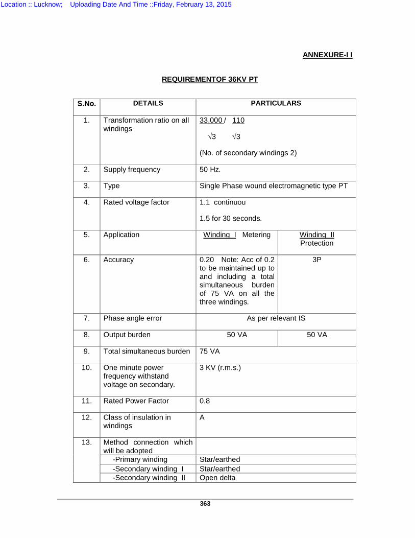
363
ANNEXURE-I I
REQUIREMENTOF 36KV PT
S.No. DETAILS PARTICULARS
1. Transformation ratio on all windings
33,000 / 110
3 3
(No. of secondary windings 2)
2. Supply frequency 50 Hz.
3. Type Single Phase wound electromagnetic type PT
4. Rated voltage factor 1.1 continuou
1.5 for 30 seconds.
5. Application Winding I Metering Winding II Protection
6. Accuracy 0.20 Note: Acc of 0.2 to be maintained up to and including a total simultaneous burden of 75 VA on all the three windings.
3P
7. Phase angle error As per relevant IS
8. Output burden 50 VA 50 VA
9. Total simultaneous burden 75 VA
10. One minute power frequency withstand voltage on secondary.
3 KV (r.m.s.)
11. Rated Power Factor 0.8
12. Class of insulation in windings
A
13. Method connection which will be adopted
-Primary winding Star/earthed -Secondary winding I Star/earthed -Secondary winding II Open delta
Location :: Lucknow; Uploading Date And Time ::Friday, February 13, 2015
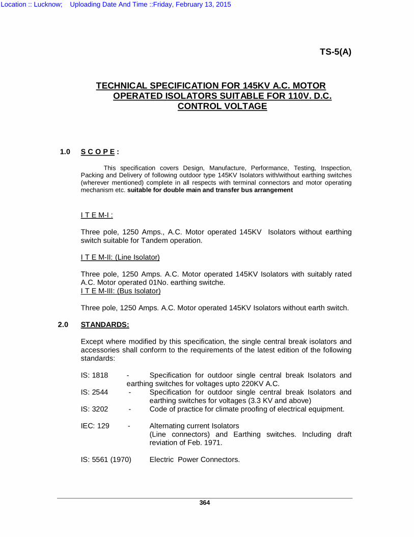
364
TS-5(A)
TECHNICAL SPECIFICATION FOR 145KV A.C. MOTOR OPERATED ISOLATORS SUITABLE FOR 110V. D.C.
CONTROL VOLTAGE
1.0 S C O P E :
This specification covers Design, Manufacture, Performance, Testing, Inspection, Packing and Delivery of following outdoor type 145KV Isolators with/without earthing switches (wherever mentioned) complete in all respects with terminal connectors and motor operating mechanism etc. suitable for double main and transfer bus arrangement
I T E M-I : Three pole, 1250 Amps., A.C. Motor operated 145KV Isolators without earthing
switch suitable for Tandem operation. I T E M-II: (Line Isolator) Three pole, 1250 Amps. A.C. Motor operated 145KV Isolators with suitably rated
A.C. Motor operated 01No. earthing switche. I T E M-III: (Bus Isolator) Three pole, 1250 Amps. A.C. Motor operated 145KV Isolators without earth switch. 2.0 STANDARDS:
Except where modified by this specification, the single central break isolators and accessories shall conform to the requirements of the latest edition of the following standards: IS: 1818 - Specification for outdoor single central break Isolators and
earthing switches for voltages upto 220KV A.C. IS: 2544 - Specification for outdoor single central break Isolators and
earthing switches for voltages (3.3 KV and above) IS: 3202 - Code of practice for climate proofing of electrical equipment. IEC: 129 - Alternating current Isolators (Line connectors) and Earthing switches. Including draft
reviation of Feb. 1971. IS: 5561 (1970) Electric Power Connectors.
Location :: Lucknow; Uploading Date And Time ::Friday, February 13, 2015
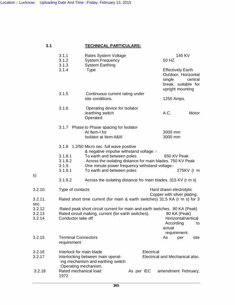
365
3.1 TECHNICAL PARTICULARS:
3.1.1 Rates System Voltage 145 KV 3.1.2 System Frequency 50 HZ 3.1.3 System Earthing 3.1.4 Type Effectively Earth
Outdoor, Horizontal single central break, suitable for upright mounting
3.1.5 Continuous current rating under site conditions. 1250 Amps.
3.1.6 Operating device for Isolator
/earthing switch A.C. Motor Operated
3.1.7 Phase to Phase spacing for Isolator
At Item-I for 3000 mm Isolator at Item-II&III 3000 mm
3.1.8 1.2/50 Micro sec. full wave positive
& negative impulse withstand voltage :- 3.1.8.1 To earth and between poles 650 KV Peak 3.1.8.2 Across the isolating distance for main blades. 750 KV Peak 3.1.9. One minute power frequency withstand voltage:- 3.1.9.1 To earth and between poles 275KV (r m s) 3.1.9.2 Across the isolating distance fro main blades. 315 KV (r m s) 3.2.10. Type of contacts Hard drawn electrolytic Copper with silver plating. 3.2.11. Rated short time current (for main & earth switches) 31.5 KA (r m s) for 3 sec. 3.2.12 Rated peak short circuit current for main and earth switches. 80 KA (Peak) 3.2.13 Rated circuit making, current (for earth switches). 80 KA (Peak) 3.2.14 Conductor take off Horizontal/vertical
According to actual requirement.
3.2.15 Terminal Connectors As per site requirement
3.2.16 Interlock for main blade Electrical 3.2.17 Interlocking between main operat- Electrical and Mechanical also. ing mechanism and earthing switch Operating mechanism. 3.2.18 Rated mechanical load As per IEC amendment February,
1972
Location :: Lucknow; Uploading Date And Time ::Friday, February 13, 2015
366
3.2.20 Auxiliary switch contacts i) Six (6) make before break contacts
(silver plated) suitable for (3No.+3NC) for protection change over Interrupting 5A DC. From one bus to another.
18 N.O. open and 18 N.C. ii) Each earthing switch shall have Six
normally open and six normally closed contacts.
3.2.21 The Isolator shall be designed to withstand seismic acceleration equivalent to 0.3 dg.
3.2.22 The Isolator shall be capable for making and breaking capacitive current of 0.7 amps.
3.2.23 Operating time of the isolator shall not exceed 12 seconds. 3.2.24 The number of Auxiliary switch contacts mentioned above are minimum
required and the actual quantity suitable for double main and transfer bus arrangement should be provided.
4.0 INTERLOCKS:
The isolator will be electrically interlocked with the associated circuit breakers in accordance with switchyard safety interlocking scheme. All accessories required on the isolator for satisfactory operation of the scheme shall be deemed to have been included in the scope of supply.
5.0 SUPPORTING STRICTIRES :
Isolator shall be sutaible for mounting on standerd structures drawing for which shall be provided by purchasure.
6.0 TERMINAL CONNECTORS : 6.1 Terminal connectors for all type of Isolators shall be as per site requirement. 6.2 The type of connectors to be provided by the contractor shall be as per IS-5561
(1970) & subject to Purchaser’s approval 7.0 EARTHING SWITCHES: 7.1 Isolators shall be equipped with earthing switches as specified complete with
operating mechanism and auxiliary contacts and will be an integral part of the isolator.
7.2 A flexible copper connection (tinned for suitably treated against corrosion) between rotating shaft of earthing switch and the frame (for connection to the station ground grid) shall have a cross section suitable to withstand short time fault current.
7.3 The earthing switch shall be motor operated and shall be constructionally interlocked with the Isolator such that earthing switches can be closed when the isolator is open and vice versa
OPERASTING MECHANISM AND CONTROL : 8.1 The AC motor operating mechanism shall actuate individual drive switches with
controls. The operating mechanism shall be capable of providing a quick, simple and effective operation. The design shall be such that a minimum of energy is required for the operation and one man shall be above to operate the isolator without undue effort.
8.2.1 The isolator shall be provided with positive continuous control through out the
entire circle of operation. The operating pipes and rods shall be sufficiently rigid
Location :: Lucknow; Uploading Date And Time ::Friday, February 13, 2015
367
to maintain positive control under most adverse conditions when operated in tension or compression for isolator operation.
8.2.2 Emergency manual operation shall be provided to enable operation of isolator in
case of power failure. When the manual operation is in progress the power operation shall become inoperative. Arrangement shall be provided to pad-lock the emergency handle when not in use.
8.3 Motor shall conform to IS: 325. The insulated winding conductor shall be of copper
and insulation shall be given fungicidal and tropical treatment as per IS 3202 Gear drive assembly shall be suitable for operating the isolator with minimum of energy. The motor enclosure shall conform to IP-55. For manual operation operating handle shall be directly coupled to gear drive having 1/33 ratio.
8.4 A weather proof control cabinet conforming to IP: 55 shall be provided to house the
driving mechanism and other accessories. The control cabinet shall be fitted with 1100 volt grade barrier type of terminal blocks. The terminal blocks shall be properly identified. The control wiring shall be carried out with a minimum of 2.5 mm cu wire of 1100V grade insulation. The auxiliary wiring with auxiliary device shall be cable of withstanding a test voltage of 2 KV for one minute.
8.5 Fail safe, solenoid type, interlocking feature shall be provided. 8.6 The control shall be so arranged that the desired operation shall be completed when
corresponding push button is pressed even momentarily. 8.7 The auxiliary contacts shall be actuated from the isolator shaft, so as to provide true
indication of the position of isolator whether operated manually or with power driven devices.
8.8 The operating handle shall be mounted on the base supporting structure, Guide
bearings shall be provided if necessary. Rust proof parts will be protected by grease retainers and covers. All bearings should have first filling of grease and provided with nipples for servicing.
8.9 An out of step relay for the three poles shall be provided to give remote pole
discrepancy alarm in the purchasers control panel. 8.10 Limit switches should be provided to prevent over travel. 8.11 A local/remote selector switch with a set of open/close push buttons (for local
operation) shall be provided on the control cabinet of the isolator. The push buttons for remote operation will be mounted on the purchasers control panel.
8.12 There shall be one operating drive for all the three poles of the isolators which shall
be GANG operated.
Similarly there shall be separate GANG OPERATED drives for the earth switches i.e.: i) Tandem Isolator will have one drive. ii) Line Isolator with 1 E/S will have two drives. iii) Bus Isolator without E/S will have one drive.
Location :: Lucknow; Uploading Date And Time ::Friday, February 13, 2015
368
8.13 There should be two numbers phase coupling pipes one on each side of the
insulator base plate for Gang operation of isolators.
For adjusting the coupling pipe lengths there should be a turn buckle type arrangement.
8.15 The operating mechanism should be placed directly and centrally below one of the
post insulators on which the two numbers phase coupling pipes are connected and the operating mechanism should directly rotate the rod placed below the centre line of the post insulator. No eccentric connection of the operating mechanism with the phase coupling pipes should be made.
9.0 CONSTRUCTIONAL FEATURES: 9.1 The isolator arms should be mechanically strong. It is preferable if the current
carrying parts of the isolator arms are separately fastened to a galvanized steel arm, so that the mechanical strength is ensured.
9.2 The operating mechanism/lever arrangement of the isolator should be such that the
isolator shall not open out in service (nor close from the open position) without a positive impulse.
10.0 ACCESSORIES: 10.1 Contacts: 10.1.1 The isolator poles shall be so designed that the contacts in service (closed position)
do not open out or cause loose contact, due to wind pressure or due to short circuit forces etc.
10.1.2 The contacts should be protected by a rain hood to avoid direct exposure to rain
water. 10.1.3 The contact head where the bus bar jumper is connected to the isolator arm should
be provided with a suitable contact bearing to avoid external flexible (braided) connections.
10.1.4 The ground terminal pads with studs each suitable for connecting to the earth mat
through M.S. Flat of size 75x10 mm shall be provided on each isolator. 10.1.5 The isolators shall be provided with high pressure current carrying contacts on the
hinge and jaw ends and all contact surfaces shall be silver plated.
All the contact joints for centre break type isolators shall be maintenance free type if possible, otherwise the tenderers may quote for contact joints requiring very little maintenance. Isolators and earth switches shall be capable of withstanding the dynamic and thermic effects of the maximum possible short circuit current of the system in their closed position. They shall be so constructed that they do not open under influence of short circuit current.
10.2 BASE : Each pole of the isolators shall be provided with a completely galvanized steel base designed for mounting on a supporting structure to be provided by the Purchaser. The base shall be rigid and self supporting. They shall also be capable of withstanding all terminal and bending stresses due to operation of the isolator.
Location :: Lucknow; Uploading Date And Time ::Friday, February 13, 2015
369
10.3 POSITION INDICATIOR :
A position indicator to show the ON & OFF position of the isolator shall be provided on each isolator pole.
10.4 COUNTER BALANCE SPRINGS : Counter balance springs shall be provided for balancing the isolators to prevent impact at the end of travel both on opening and closing of the isolator.
NAME PLATE: Isolators earthing switches and their operating devices shall be provided with a name plate. The details of the name plates shall be as given below:- a) Isolators :
- Name of manufacturer. - Designation type.
- Specification Number. - Serial Number.
- Rated Voltage. - Impulse withstand voltage to earth.
- Rated current. - Rated short time current.
- Rated maximum duration of short time current. - Rated mechanical terminal load.
- Weight. b) Earthing Switch:
- Name of manufacturer. - Designation type.
- Specification Number.
- Serial Number.
- Rated Voltage. - Impulse withstand voltage to earth.
- Rated short time current. - Rated maximum duration of short time current.
- Rated mechanical terminal load. - Weight.
c) Operating Devices : - Name of manufacturer.
- Designation type. - Rated A.C. Voltage and H.P.
- Weight.
Location :: Lucknow; Uploading Date And Time ::Friday, February 13, 2015

370
11.0 TEST & TEST CERTIFICATE :
11.1 Type test certificates for the Isolators, for all the test performed in accordance with
the relevant IS/IEC recommendation of the IEC-129 titled 'Alternating Current' isolators (line connector) and earthing switches including the draft revision of Feb. 1971 and ISS 9921 shall be furnished alongwith the proposal.
11.2 Any offer which does not include type test report is liable to be rejected summarily. 11.3 The following acceptance/routine test in accordance with the recommendation of
IEC-129 & ISS 9921 shall be furnished for Purchaser’s approval before dispatch of the isolators.
11.4 ROUTINE TESTS : (IEC-129-1975):
The isolators before transportation shall be subjected to following routine factory tests :-
i) Power frequency Voltage (Dry & Wet) Tests:
One pole complete with insulators shall be tested in the works, of remaining, 10% of insulators will be subject to test.
i) Voltage test of auxiliary circuits (Clause-46) ii) Mechanical operating test (Clause-46). iii) Measurement of the resistance of the main circuit (Clause-47)
11.5 The following type tests as per relevant IS/IEC shall be performed on one unit and report be submitted with the tender:-
i) Dielectric Test ii) Lightning Impulse Voltage tests iii) Switching impulse voltage tests iv) Power frequency voltage tests v) Artificial pollution tests vi) Test of auxiliary and control circuit vii) Temperature rise tests viii) Short time withstand current & peak withstand ix) Operating and mechanical endurance test x) Tests for measuring radio interference level xi) Corona extinction voltage tests:- 12.0 DRAWNGS :
Drawing incorporating the following particulars shall be submitted with the offer for the purpose of preliminary study :- i) Complete assembly drawing showing plan and elevation views of the 3
phase and single phase isolators, earthing switches complete with details of operating mechanism, mounting dimensions etc.
ii) Sketches and descriptive details of : a) Isolators. b) Bearing & sag compensating soaring. c) Jaw contacts and main isolator baldes. d) Interlocking devices. e) Earthing switches.
Location :: Lucknow; Uploading Date And Time ::Friday, February 13, 2015
371
f) Interrupting device for making and breaking. g) Operating mechanism. h) Spring operation etc. i) Foundation Plan including weights of various components and impact
loadings. iii) It is essential to furnish drawings to satisfy the purchaser about the
suitability of the jaw design. iv) The drawing to be furnished by the Contractor for approval after acceptance
of his tender, shall include the following particulars (all explanations, legends etc., shall be given in English and dimensions shall be marked in Metric Units).
a) Complete assembly drawings showing plan and elevation views of the isolator with mounting dimensions net and shipping weights etc.
b) Exhausting itemized bill of materials. c) Control & wiring diagram (including inter pole wiring diagram) clearly
indicating various No/NC contacts used as well as spare for individual pole and earthing switch.
d) Electrical control schematic diagrams, wiring diagrams, interconnection diagrams on the equipment, including Alarm protective devices, indicating devices, instruments and space heaters.
e) Terminal Board drawing of common control Board showing wire No. and Terminal block No. and indicating purpose for use.
f) Fully dimensional drawing of Terminal Connectors showing all the views, weight, material composition current carrying capacity and temperature rise.
After approval of the preliminary drawings, reproducible copies of each drawing shall be supplied. Final drawings shall be certified as correct for construction.
Location :: Lucknow; Uploading Date And Time ::Friday, February 13, 2015
372
TS-5(B) TECHNICAL SPECIFICATIONS FOR 36 kV ISOLATORS
1.0 STANDARDS
For standards please refer the specifications for 145 kV isolators.
2.0 TYPE OF ISOLATORS
a) Three phase, 1250 A, 36 kV manually operated, Standard isolators without earth switch.
b) Three phase, 1250 A, 36 kV manually operated, Standard isolators
with one earth switch.
3.0 PRINCIPAL PARAMETERS
Sl. No. DETAILS 36 kV Isolator
1 Rated Voltage 36 kV 2 System frequency 50 Hz 3 System Earthing Effectively earthed
4 Type of Isolator Outdoor, Horizontal air break suitable for upright mounting
5 Continuous current rating 1250 A
6 Operating mechanism Manual 7 Phase to phase spacing 1500 mm 8 Rated short time withstand current 25 kA (rms) 9 Rated peak short circuit current 62.5 kA (peak) 10 Temperature rise As per IEC-129 derated for an
ambient of 500C 11 Seismic co-efficient 0.3 g.
12. 1.2/50 microsecond full wave positive and negative impulse withstand voltage to earth
70 kV (peak)
13. One minute power frequency withstand voltage dry & wet to earth
70 kV (rms)
14. Auxiliary Contacts 4 normally open and 4 normally closed.
15 Insulation level of insulators
i) Impulse voltage withstand test (1.2/50 micro second full wave)
170 kV (peak)
Location :: Lucknow; Uploading Date And Time ::Friday, February 13, 2015
373
ii) Power frequency withstand voltage to earth (dry & wet)
70 kV (rms)
16 Creepage distance of insulators : 900 mm i) Total
ii) Protected 450 mm
17 Minimum strength : Suitable to withstand wind, short circuit and operating forces
i) Torsional ii) Cantilever
18 Interlocks with circuit breaker
1 set of electrical and castel type interlocks.
19 Type of contacts Hard drawn electrolytic copper with silver plating
20
Conductor take off
Horizontal/vertical according to actual requirement.
21. Phase-to phase clearance 1500 mm
4.0 TERMINAL CONNECTORS
4.1 Each Isolator shall be provided with appropriate number of suitable for twin ACSR Zebra/Panther conductors as specified in ‘General Technical Requirements’ and approved drawings.
5.0 INTERLOCKS
It is proposed to electrically interlock the Isolators with the associated
33kV circuit breakers in accordance with switchyard safety interlocking scheme such that the Isolators can not be manually operated if the 33 kV breaker is on. The bidder will furnish details of the electrical interlocking scheme proposed by him. Any and all accessories required on the isolator side for satisfactory operation of the scheme shall be deemed to be in the scope of the supply. Interlocking arrangement shall be of failsafe type.
6.0 OPERATING MECHANISM AND CONTROL:
A lever shall be provided for manual operation of the isolator.
Arrangement shall be provided to padlock lever when not in use.
7.0 CONSTRUCTION FEATURES: As per 145 kV isolators.
8.0 ACCESSORIES: As per 145 kV isolators
9.0 NAME PLATES:
Location :: Lucknow; Uploading Date And Time ::Friday, February 13, 2015
374
Isolators shall be provided with the name plates. The name plates shall be
weatherproof and corrosion proof. It shall be mounted in such a position that it shall be visible in the position of normal service and installation. It shall carry the following informations:
(a) Name of the manufacturer (b) Designation type (c) Serial number (d) Rated voltage (e) Impulse withstand voltage to earth (f) Rated current (g) Rate short time current (h) Rated maximum duration of short time current
10.0 INSULATORS The Bus post insulators will have a top housing pitch circle Dia. of 127
mm. The insulators will confirm to IEC-168.
11.0 TESTS For details of test certificates, routine and type tests to be performed, as
mentioned in the 145 kV isolators.
12.0 DRAWING AND DATA As per 145 kV isolators
13.0 SUPPORTING STRUCTURES The isolators shall be suitable to be mounted on auxiliary structures as per
general technical requirements.
Location :: Lucknow; Uploading Date And Time ::Friday, February 13, 2015
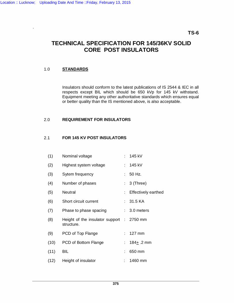
375
. TS-6
TECHNICAL SPECIFICATION FOR 145/36KV SOLID CORE POST INSULATORS
1.0 STANDARDS
Insulators should conform to the latest publications of IS 2544 & IEC in all respects except BIL which should be 650 kVp for 145 kV withstand. Equipment meeting any other authoritative standards which ensures equal or better quality than the IS mentioned above, is also acceptable.
2.0 REQUIREMENT FOR INSULATORS
2.1 FOR 145 KV POST INSULATORS
(1) Nominal voltage : 145 kV
(2) Highest system voltage : 145 kV
(3) Sytem frequency : 50 Hz.
(4) Number of phases : 3 (Three)
(5) Neutral : Effectively earthed
(6) Short circuit current : 31.5 KA
(7) Phase to phase spacing : 3.0 meters
(8) Height of the insulator support structure.
: 2750 mm
(9) PCD of Top Flange : 127 mm
(10) PCD of Bottom Flange : 184+ .2 mm
(11) BIL : 650 mm
(12) Height of insulator : 1460 mm
Location :: Lucknow; Uploading Date And Time ::Friday, February 13, 2015
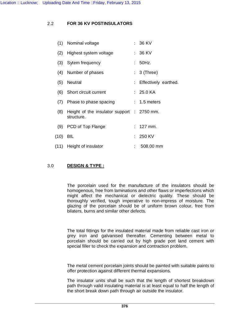
376
2.2 FOR 36 KV POSTINSULATORS
(1) Nominal voltage : 36 KV
(2) Highest system voltage : 36 KV
(3) Sytem frequency : 50Hz.
(4) Number of phases : 3 (Three)
(5) Neutral : Effectively earthed.
(6) Short circuit current : 25.0 KA
(7) Phase to phase spacing : 1.5 meters
(8) Height of the insulator support structure.
: 2750 mm.
(9) PCD of Top Flange : 127 mm.
(10) BIL : 250 KV
(11) Height of insulator : 508.00 mm
3.0 DESIGN & TYPE :
The porcelain used for the manufacture of the insulators should be homogenous, free from laminations and other flaws or imperfections which might affect the mechanical or dielectric quality. These should be thoroughly verified, tough imperative to non-impress of moisture. The glazing of the porcelain should be of uniform brown colour, free from bilaters, burns and similar other defects.
The total fittings for the insulated material made from reliable cast iron or grey iron and galvanised thereafter. Cementing between metal to porcelain should be carried out by high grade port land cement with special filler to check the expansion and contraction problem.
The metal cement porcelain joints should be painted with suitable paints to offer protection against different thermal expansions.
The insulator units shall be such that the length of shortest breakdown path through valid insulating material is at least equal to half the length of the short break down path through air outside the insulator.
Location :: Lucknow; Uploading Date And Time ::Friday, February 13, 2015
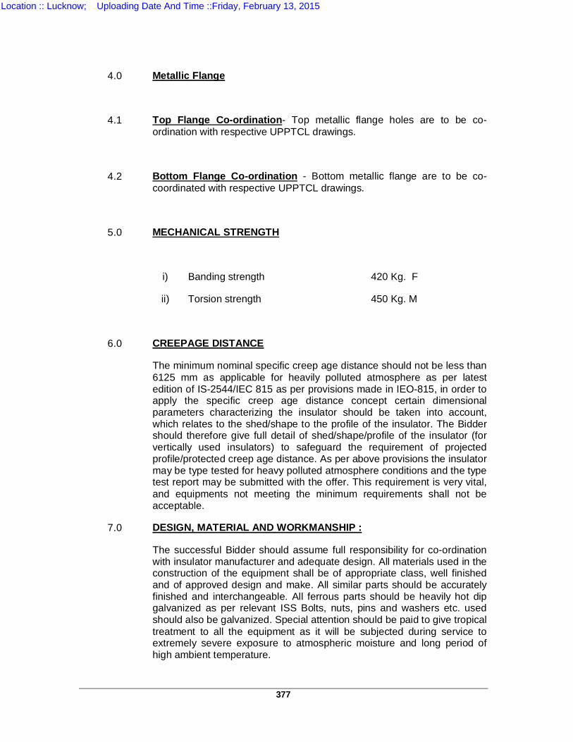
377
4.0 Metallic Flange
4.1 Top Flange Co-ordination- Top metallic flange holes are to be co-ordination with respective UPPTCL drawings.
4.2 Bottom Flange Co-ordination - Bottom metallic flange are to be co-coordinated with respective UPPTCL drawings.
5.0 MECHANICAL STRENGTH
i) Banding strength 420 Kg. F
ii) Torsion strength 450 Kg. M
6.0 CREEPAGE DISTANCE
The minimum nominal specific creep age distance should not be less than 6125 mm as applicable for heavily polluted atmosphere as per latest edition of IS-2544/IEC 815 as per provisions made in IEO-815, in order to apply the specific creep age distance concept certain dimensional parameters characterizing the insulator should be taken into account, which relates to the shed/shape to the profile of the insulator. The Bidder should therefore give full detail of shed/shape/profile of the insulator (for vertically used insulators) to safeguard the requirement of projected profile/protected creep age distance. As per above provisions the insulator may be type tested for heavy polluted atmosphere conditions and the type test report may be submitted with the offer. This requirement is very vital, and equipments not meeting the minimum requirements shall not be acceptable.
7.0 DESIGN, MATERIAL AND WORKMANSHIP :
The successful Bidder should assume full responsibility for co-ordination with insulator manufacturer and adequate design. All materials used in the construction of the equipment shall be of appropriate class, well finished and of approved design and make. All similar parts should be accurately finished and interchangeable. All ferrous parts should be heavily hot dip galvanized as per relevant ISS Bolts, nuts, pins and washers etc. used should also be galvanized. Special attention should be paid to give tropical treatment to all the equipment as it will be subjected during service to extremely severe exposure to atmospheric moisture and long period of high ambient temperature.
Location :: Lucknow; Uploading Date And Time ::Friday, February 13, 2015
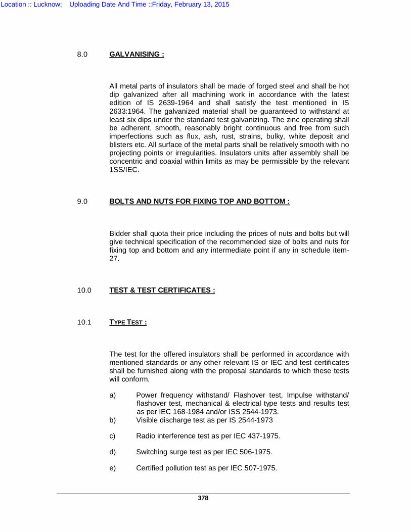
378
8.0 GALVANISING :
All metal parts of insulators shall be made of forged steel and shall be hot dip galvanized after all machining work in accordance with the latest edition of IS 2639-1964 and shall satisfy the test mentioned in IS 2633:1964. The galvanized material shall be guaranteed to withstand at least six dips under the standard test galvanizing. The zinc operating shall be adherent, smooth, reasonably bright continuous and free from such imperfections such as flux, ash, rust, strains, bulky, white deposit and blisters etc. All surface of the metal parts shall be relatively smooth with no projecting points or irregularities. Insulators units after assembly shall be concentric and coaxial within limits as may be permissible by the relevant 1SS/IEC.
9.0 BOLTS AND NUTS FOR FIXING TOP AND BOTTOM :
Bidder shall quota their price including the prices of nuts and bolts but will give technical specification of the recommended size of bolts and nuts for fixing top and bottom and any intermediate point if any in schedule item-27.
10.0 TEST & TEST CERTIFICATES :
10.1 TYPE TEST :
The test for the offered insulators shall be performed in accordance with mentioned standards or any other relevant IS or IEC and test certificates shall be furnished along with the proposal standards to which these tests will conform.
a) Power frequency withstand/ Flashover test, Impulse withstand/ flashover test, mechanical & electrical type tests and results test as per IEC 168-1984 and/or ISS 2544-1973.
b) Visible discharge test as per IS 2544-1973
c) Radio interference test as per IEC 437-1975.
d) Switching surge test as per IEC 506-1975.
e) Certified pollution test as per IEC 507-1975.
Location :: Lucknow; Uploading Date And Time ::Friday, February 13, 2015
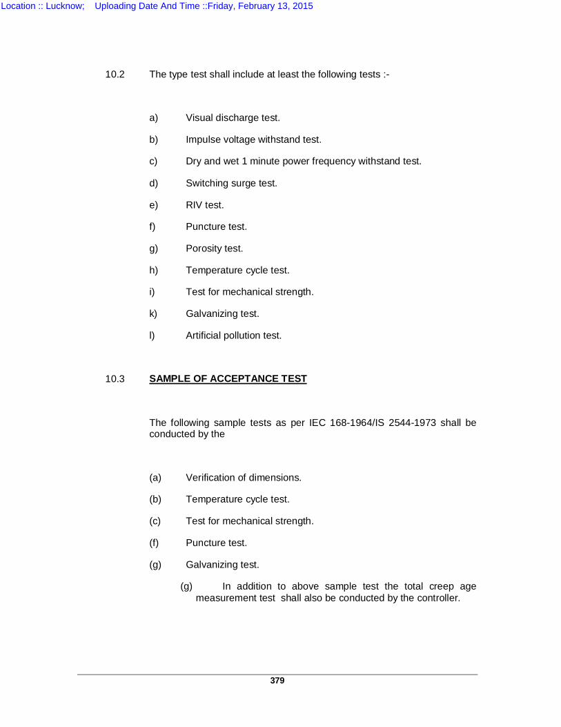
379
10.2 The type test shall include at least the following tests :-
a) Visual discharge test.
b) Impulse voltage withstand test.
c) Dry and wet 1 minute power frequency withstand test.
d) Switching surge test.
e) RIV test.
f) Puncture test.
g) Porosity test.
h) Temperature cycle test.
i) Test for mechanical strength.
k) Galvanizing test.
l) Artificial pollution test.
10.3 SAMPLE OF ACCEPTANCE TEST
The following sample tests as per IEC 168-1964/IS 2544-1973 shall be conducted by the
(a) Verification of dimensions.
(b) Temperature cycle test.
(c) Test for mechanical strength.
(f) Puncture test.
(g) Galvanizing test.
(g) In addition to above sample test the total creep age measurement test shall also be conducted by the controller.
Location :: Lucknow; Uploading Date And Time ::Friday, February 13, 2015
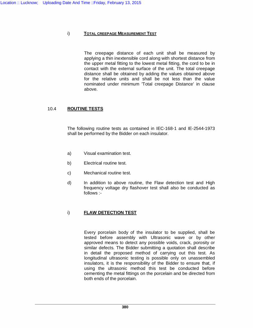
380
i) TOTAL CREEPAGE MEASUREMENT TEST
The creepage distance of each unit shall be measured by applying a thin inextensible cord along with shortest distance from the upper metal fitting to the lowest metal fitting, the cord to be in contact with the external surface of the unit. The total creepage distance shall be obtained by adding the values obtained above for the relative units and shall be not less than the value nominated under minimum 'Total creepage Distance' in clause above.
10.4 ROUTINE TESTS
The following routine tests as contained in IEC-168-1 and IE-2544-1973 shall be performed by the Bidder on each insulator.
a) Visual examination test.
b) Electrical routine test.
c) Mechanical routine test.
d) In addition to above routine, the Flaw detection test and High frequency voltage dry flashover test shall also be conducted as follows :-
i) FLAW DETECTION TEST
Every porcelain body of the insulator to be supplied, shall be tested before assembly with Ultrasonic wave or by other approved means to detect any possible voids, crack, porosity or similar defects. The Bidder submitting a quotation shall describe in detail the proposed method of carrying out this test. As longitudinal ultrasonic testing is possible only on unassembled insulators, it is the responsibility of the Bidder to ensure that, if using the ultrasonic method this test be conducted before cementing the metal fittings on the porcelain and be directed from both ends of the porcelain.
Location :: Lucknow; Uploading Date And Time ::Friday, February 13, 2015
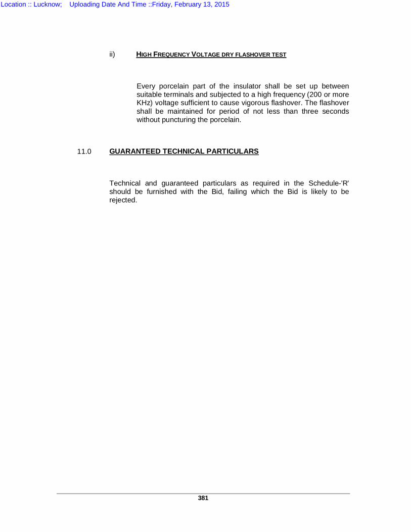
381
ii) HIGH FREQUENCY VOLTAGE DRY FLASHOVER TEST
Every porcelain part of the insulator shall be set up between suitable terminals and subjected to a high frequency (200 or more KHz) voltage sufficient to cause vigorous flashover. The flashover shall be maintained for period of not less than three seconds without puncturing the porcelain.
11.0 GUARANTEED TECHNICAL PARTICULARS
Technical and guaranteed particulars as required in the Schedule-'R' should be furnished with the Bid, failing which the Bid is likely to be rejected.
Location :: Lucknow; Uploading Date And Time ::Friday, February 13, 2015
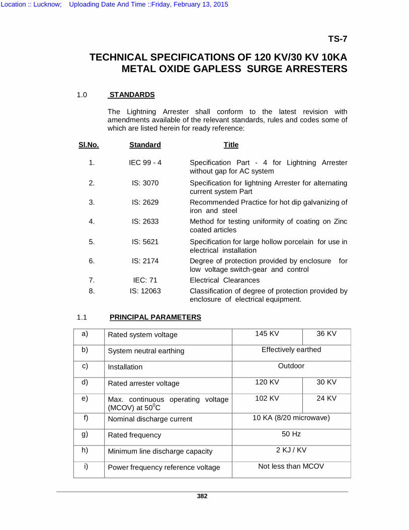
382
TS-7
TECHNICAL SPECIFICATIONS OF 120 KV/30 KV 10KA METAL OXIDE GAPLESS SURGE ARRESTERS
1.0 STANDARDS The Lightning Arrester shall conform to the latest revision with
amendments available of the relevant standards, rules and codes some of which are listed herein for ready reference:
Sl.No. Standard Title
1. IEC 99 - 4
Specification Part - 4 for Lightning Arrester without gap for AC system
2. IS: 3070 Specification for lightning Arrester for alternating current system Part
3. IS: 2629 Recommended Practice for hot dip galvanizing of iron and steel
4. IS: 2633
Method for testing uniformity of coating on Zinc coated articles
5. IS: 5621 Specification for large hollow porcelain for use in electrical installation
6. IS: 2174 Degree of protection provided by enclosure for low voltage switch-gear and control
7. IEC: 71 Electrical Clearances 8. IS: 12063 Classification of degree of protection provided by
enclosure of electrical equipment.
1.1 PRINCIPAL PARAMETERS
a) Rated system voltage 145 KV 36 KV
b) System neutral earthing Effectively earthed
c) Installation Outdoor
d) Rated arrester voltage 120 KV 30 KV
e) Max. continuous operating voltage (MCOV) at 500C
102 KV 24 KV
f) Nominal discharge current 10 KA (8/20 microwave)
g) Rated frequency 50 Hz
h) Minimum line discharge capacity 2 KJ / KV
i) Power frequency reference voltage Not less than MCOV
Location :: Lucknow; Uploading Date And Time ::Friday, February 13, 2015
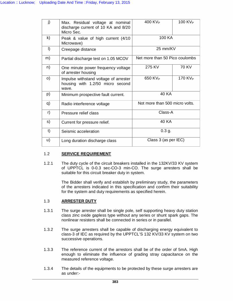
383
j) Max. Residual voltage at nominal
discharge current of 10 KA and 8/20 Micro Sec.
400 KVP 100 KVP
k) Peak & value of high current (4/10 Microwave)
100 KA
l) Creepage distance 25 mm/KV
m) Partial discharge test on 1.05 MCOV Net more than 50 Pico coulombs
n) One minute power frequency voltage of arrester housing
275 KV 70 KV
o) Impulse withstand voltage of arrester housing with 1.2/50 micro second wave.
650 KVP 170 KVP
p) Minimum prospective fault current. 40 KA
q) Radio interference voltage Not more than 500 micro volts.
r) Pressure relief class Class-A
s) Current for pressure relief. 40 KA
t) Seismic acceleration 0.3 g.
u) Long duration discharge class Class 3 (as per IEC)
1.2 SERVICE REQUIREMENT 1.2.1 The duty cycle of the circuit breakers installed in the 132KV/33 KV system
of UPPTCL is 0-0.3 sec-CO-3 min-CO. The surge arresters shall be suitable for this circuit breaker duty in system.
The Bidder shall verify and establish by preliminary study, the parameters
of the arresters indicated in this specification and confirm their suitability for the system and duty requirements as specified herein.
1.3 ARRESTER DUTY 1.3.1 The surge arrester shall be single pole, self supporting heavy duty station
class zinc oxide gapless type without any series or shunt spark gaps. The nonlinear resisters shall be connected in series or in parallel.
1.3.2 The surge arresters shall be capable of discharging energy equivalent to
class-3 of IEC as required by the UPPTCL’S 132 KV/33 KV system on two successive operations.
1.3.3 The reference current of the arrestors shall be of the order of 5mA. High
enough to eliminate the influence of grading stray capacitance on the measured reference voltage.
1.3.4 The details of the equipments to be protected by these surge arresters are
as under:-
Location :: Lucknow; Uploading Date And Time ::Friday, February 13, 2015
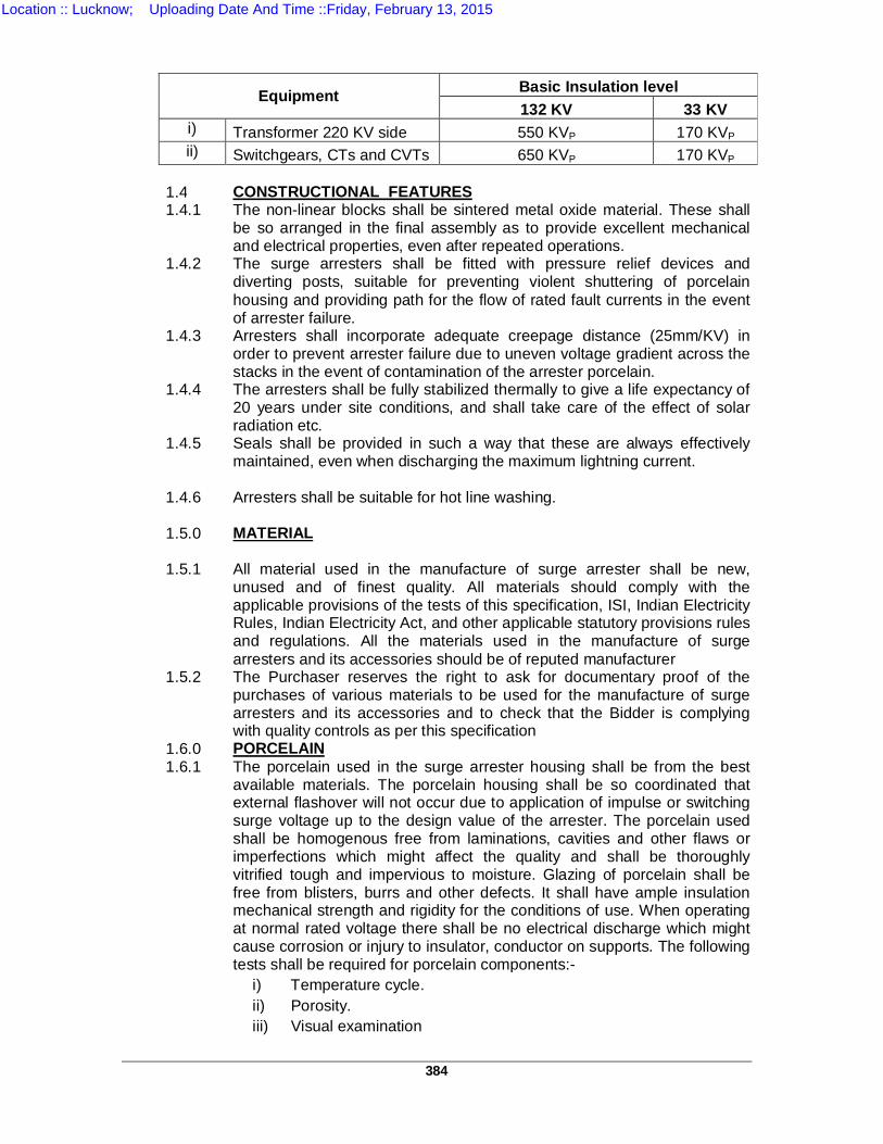
384
Equipment Basic Insulation level 132 KV 33 KV
i) Transformer 220 KV side 550 KVP 170 KVP ii) Switchgears, CTs and CVTs 650 KVP 170 KVP
1.4 CONSTRUCTIONAL FEATURES 1.4.1 The non-linear blocks shall be sintered metal oxide material. These shall
be so arranged in the final assembly as to provide excellent mechanical and electrical properties, even after repeated operations.
1.4.2 The surge arresters shall be fitted with pressure relief devices and diverting posts, suitable for preventing violent shuttering of porcelain housing and providing path for the flow of rated fault currents in the event of arrester failure.
1.4.3 Arresters shall incorporate adequate creepage distance (25mm/KV) in order to prevent arrester failure due to uneven voltage gradient across the stacks in the event of contamination of the arrester porcelain.
1.4.4 The arresters shall be fully stabilized thermally to give a life expectancy of 20 years under site conditions, and shall take care of the effect of solar radiation etc.
1.4.5 Seals shall be provided in such a way that these are always effectively maintained, even when discharging the maximum lightning current.
1.4.6 Arresters shall be suitable for hot line washing. 1.5.0 MATERIAL 1.5.1 All material used in the manufacture of surge arrester shall be new,
unused and of finest quality. All materials should comply with the applicable provisions of the tests of this specification, ISI, Indian Electricity Rules, Indian Electricity Act, and other applicable statutory provisions rules and regulations. All the materials used in the manufacture of surge arresters and its accessories should be of reputed manufacturer
1.5.2 The Purchaser reserves the right to ask for documentary proof of the purchases of various materials to be used for the manufacture of surge arresters and its accessories and to check that the Bidder is complying with quality controls as per this specification
1.6.0 PORCELAIN 1.6.1 The porcelain used in the surge arrester housing shall be from the best
available materials. The porcelain housing shall be so coordinated that external flashover will not occur due to application of impulse or switching surge voltage up to the design value of the arrester. The porcelain used shall be homogenous free from laminations, cavities and other flaws or imperfections which might affect the quality and shall be thoroughly vitrified tough and impervious to moisture. Glazing of porcelain shall be free from blisters, burrs and other defects. It shall have ample insulation mechanical strength and rigidity for the conditions of use. When operating at normal rated voltage there shall be no electrical discharge which might cause corrosion or injury to insulator, conductor on supports. The following tests shall be required for porcelain components:-
i) Temperature cycle. ii) Porosity. iii) Visual examination
Location :: Lucknow; Uploading Date And Time ::Friday, February 13, 2015
385
1.7 METAL PARTS 1.7.1 All iron parts shall be hot dip, galvanised. Joints shall be made air tight
surfaces of joints shall be turned up porcelain parts by grinding and metal parts by machining to ensure a uniform compressive pressure.
1.7.2 Steel bolts, nuts, washers and check nuts should be hot dip galvanised
conforming to IS:1363-1967, IS:1367-1961 and latest amendment thereof. This should be of reputed manufacturer and should bear ISI mark.
1.8 FITTING AND ACCESSORIES 1.8.1 INSULATION BASE Insulating base offered for the surge arrester, shall be manufactured from
the best available porcelain. One number insulating base shall be supplied by the Bidder with each surge arrester.
1.8.2 SURGE COUNTER Self containing discharge counter, enclosed suitably for outdoor use &
requiring no auxiliary or battery supply for operation, shall be provided for each single pole unit. The surge counters on cyclometric dial shall be robust and of adequate size. These shall be so located that incoming and outgoing connections are made with minimum possible blend and incoming & outgoing connections shall be provided with at least 2 nos. bolts each. The discharge counters shall be suitably mounted on the support structure of the surge arresters so that the counter shall be visible through an inspection window and should be readable from ground level. The internal connections of surge counters shall be provided to carry large surge currents as per surge arrester specifications.
The cubicle housing the surge counters shall be made of 12 SWG sheet
and it should be water tight and vermin proof. 1.8.3 MILLI AMMETERS Suitable milli ammeters (without push buttons) on each pole of the
arrester, with appropriate connections, shall be supplied to measure the leakage currents. The milli ammeter shall be suitably mounted on the support structure of the arrester, suitable means to differentiate between the internal grading currents and external leakage currents shall be indicated.
1.8.4 GRADING CORONA RING Suitable grading corona ring shall be provided on each complete arrester
unit as required for proper stress distribution. 1.9 TERMINAL CONNECTORS 1.9.1 The arresters shall be provided with line side terminal connectors made
out of hot dip galvanised suitable for specified ACSR conductors for vertical as well as horizontal entry.
Location :: Lucknow; Uploading Date And Time ::Friday, February 13, 2015
386
1.9.2 Two ground terminals diagonally opposite suitable for connecting 50x6
mm GI earth strip shall be provided each with two holes of size M-10 horizontally and suitable for the above strip.
1.9.3 The design of connectors shall be such as to give firm contact between
connectors. They should offer protection to contact surface against effects of leakage between dissimilar metals and atmospheric corrosion. The connectors shall have sufficient mechanical strength and shall completely enclose the conductor and terminal. It shall hold the conductor and terminal so that the connector with stand mechanical stresses set up by vibration, wind and short circuit currents. The conductivity of the connectors should be high so that the power loss is minimum.
1.9.4 It should be designed with high factor of safety and conform in respect of
temperature rise, resistance and tensile strength to ISI 5561-1970 and latest amendment thereof.
1.9.5 The terminal connectors should be suitable to carry large surge currents
for duration of microseconds and short duration short circuit power frequency currents.
1.9.6 The connectors shall have at least 4 nos. of 12mm dia bolts and nuts with
washers and check nuts and should be located as close to the conductor as possible.
1.9.7 The contact surface should be neat, clean, smooth and should be such
that the corona effect is minimum as far as possible. 1.9.8 All castings shall be free from blow holes, tracks sharp edges and other
casting defects. 1.9.9 All current carrying parts shall be designed and manufactured for the
minimum contact resistance. 1.9.10 The Bidder shall submit the detail drawing of the terminal connectors and
their test certificates. 1.10 TYPE OF MOUNTING The surge arresters together with insulating case and surge monitors
should be suitable for upright mounting on auxiliary steel structure as per UPPTCL standard drawing. Electro galvanized steel bolts, nuts, washers and check nuts for mounting the lightning arresters shall be supplied by the Bidder along with arresters. The PCD and no. of holes in the base mounting flange shall be in accordance with the Purchaser's requirement to suit the auxiliary structure.
1.11 TESTS The surge arresters shall conform to type tests and shall be subjected to
routine and acceptance tests in accordance with IEC 99.4 (1991) and other relevant standards.
Location :: Lucknow; Uploading Date And Time ::Friday, February 13, 2015
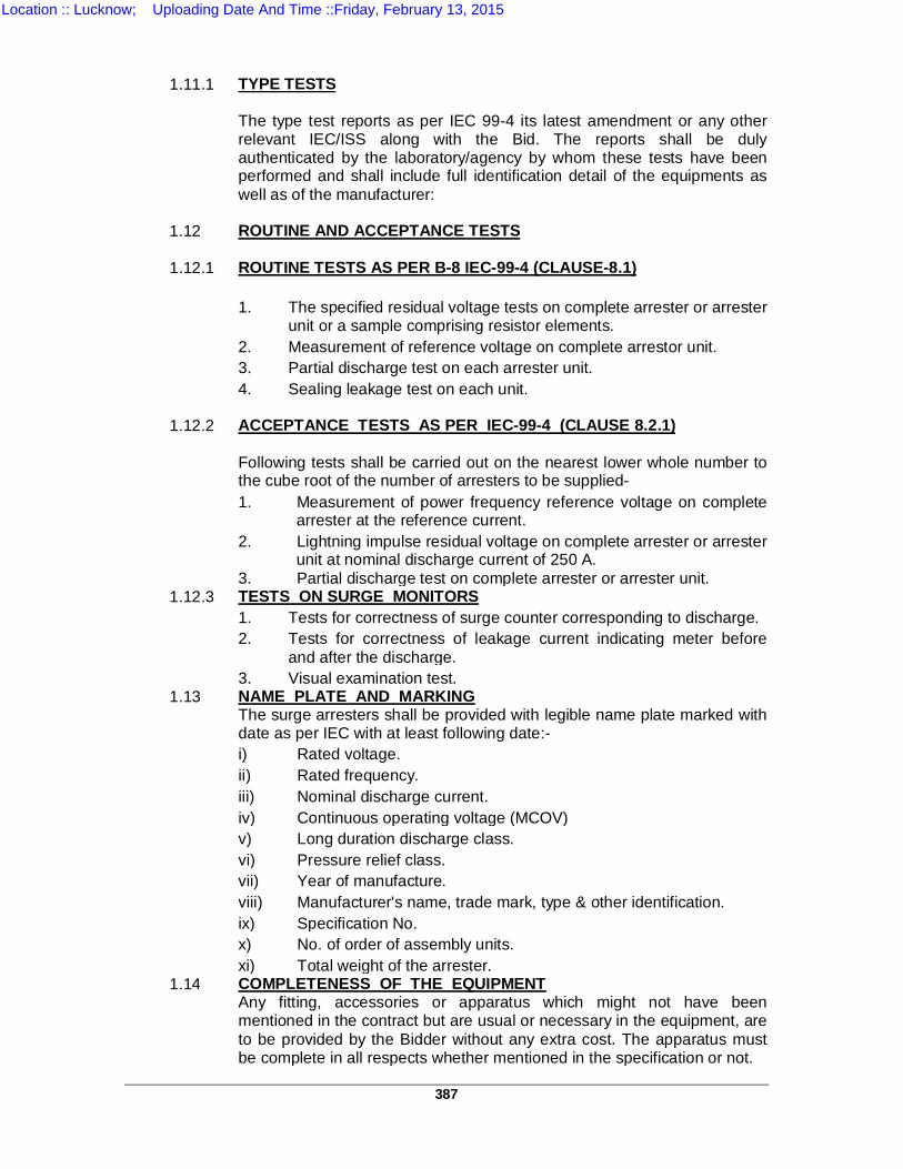
387
1.11.1 TYPE TESTS The type test reports as per IEC 99-4 its latest amendment or any other
relevant IEC/ISS along with the Bid. The reports shall be duly authenticated by the laboratory/agency by whom these tests have been performed and shall include full identification detail of the equipments as well as of the manufacturer:
1.12 ROUTINE AND ACCEPTANCE TESTS 1.12.1 ROUTINE TESTS AS PER B-8 IEC-99-4 (CLAUSE-8.1) 1. The specified residual voltage tests on complete arrester or arrester
unit or a sample comprising resistor elements. 2. Measurement of reference voltage on complete arrestor unit. 3. Partial discharge test on each arrester unit. 4. Sealing leakage test on each unit. 1.12.2 ACCEPTANCE TESTS AS PER IEC-99-4 (CLAUSE 8.2.1) Following tests shall be carried out on the nearest lower whole number to
the cube root of the number of arresters to be supplied- 1. Measurement of power frequency reference voltage on complete
arrester at the reference current. 2. Lightning impulse residual voltage on complete arrester or arrester
unit at nominal discharge current of 250 A. 3. Partial discharge test on complete arrester or arrester unit. 1.12.3 TESTS ON SURGE MONITORS 1. Tests for correctness of surge counter corresponding to discharge. 2. Tests for correctness of leakage current indicating meter before
and after the discharge. 3. Visual examination test. 1.13 NAME PLATE AND MARKING The surge arresters shall be provided with legible name plate marked with
date as per IEC with at least following date:- i) Rated voltage. ii) Rated frequency. iii) Nominal discharge current. iv) Continuous operating voltage (MCOV) v) Long duration discharge class. vi) Pressure relief class. vii) Year of manufacture. viii) Manufacturer's name, trade mark, type & other identification. ix) Specification No. x) No. of order of assembly units. xi) Total weight of the arrester. 1.14 COMPLETENESS OF THE EQUIPMENT Any fitting, accessories or apparatus which might not have been
mentioned in the contract but are usual or necessary in the equipment, are to be provided by the Bidder without any extra cost. The apparatus must be complete in all respects whether mentioned in the specification or not.
Location :: Lucknow; Uploading Date And Time ::Friday, February 13, 2015
388
CONTROL & RELAY PANELS WITH
SUBSTATION AUTOMATION SYSTEMS
Location :: Lucknow; Uploading Date And Time ::Friday, February 13, 2015
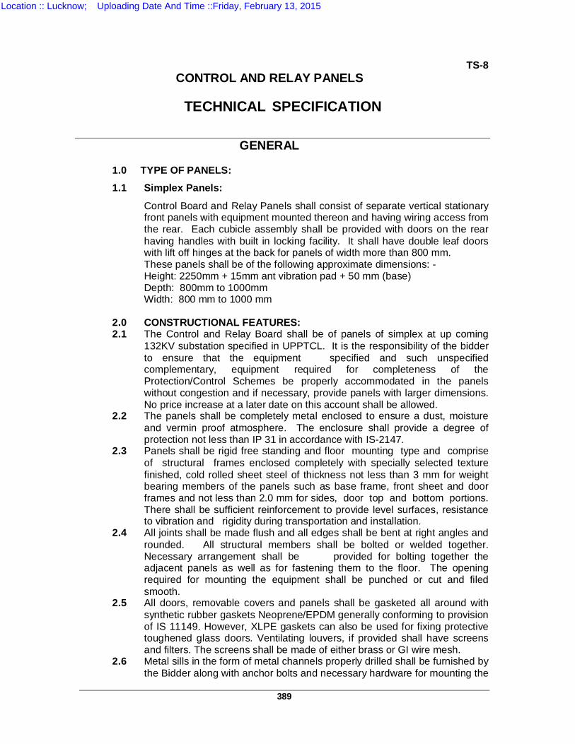
389
TS-8 CONTROL AND RELAY PANELS
GENERAL
1.0 TYPE OF PANELS:
1.1 Simplex Panels:
Control Board and Relay Panels shall consist of separate vertical stationary front panels with equipment mounted thereon and having wiring access from the rear. Each cubicle assembly shall be provided with doors on the rear having handles with built in locking facility. It shall have double leaf doors with lift off hinges at the back for panels of width more than 800 mm. These panels shall be of the following approximate dimensions: - Height: 2250mm + 15mm ant vibration pad + 50 mm (base) Depth: 800mm to 1000mm Width: 800 mm to 1000 mm
2.0 CONSTRUCTIONAL FEATURES: 2.1 The Control and Relay Board shall be of panels of simplex at up coming
132KV substation specified in UPPTCL. It is the responsibility of the bidder to ensure that the equipment specified and such unspecified complementary, equipment required for completeness of the Protection/Control Schemes be properly accommodated in the panels without congestion and if necessary, provide panels with larger dimensions. No price increase at a later date on this account shall be allowed.
2.2 The panels shall be completely metal enclosed to ensure a dust, moisture and vermin proof atmosphere. The enclosure shall provide a degree of protection not less than IP 31 in accordance with IS-2147.
2.3 Panels shall be rigid free standing and floor mounting type and comprise of structural frames enclosed completely with specially selected texture finished, cold rolled sheet steel of thickness not less than 3 mm for weight bearing members of the panels such as base frame, front sheet and door frames and not less than 2.0 mm for sides, door top and bottom portions. There shall be sufficient reinforcement to provide level surfaces, resistance to vibration and rigidity during transportation and installation.
2.4 All joints shall be made flush and all edges shall be bent at right angles and rounded. All structural members shall be bolted or welded together. Necessary arrangement shall be provided for bolting together the adjacent panels as well as for fastening them to the floor. The opening required for mounting the equipment shall be punched or cut and filed smooth.
2.5 All doors, removable covers and panels shall be gasketed all around with synthetic rubber gaskets Neoprene/EPDM generally conforming to provision of IS 11149. However, XLPE gaskets can also be used for fixing protective toughened glass doors. Ventilating louvers, if provided shall have screens and filters. The screens shall be made of either brass or GI wire mesh.
2.6 Metal sills in the form of metal channels properly drilled shall be furnished by the Bidder along with anchor bolts and necessary hardware for mounting the
TECHNICAL SPECIFICATION
Location :: Lucknow; Uploading Date And Time ::Friday, February 13, 2015

390
panels. These shall be dispatched six months in advance of the despatch of the respective panels, so that they may be installed and leveled when concrete foundations are poured or roof ceilings are laid. Panels shall have additional rolled channel plinth at the bottom with smooth bearing surface. The panels shall be fixed on the embedded foundation channels with intervening layers of antivibration strips made of shock absorbing materials which shall be supplied by the Bidder
2.7 All control cables shall be laid in a cable gallery or trench under the control
room/Bay Kiosk/ PRR. Cable entries to the panels shall be from the bottom. The bottom plates of the panels shall be fitted with removable gland plates for fixing the cable glands, the size of which shall suit the purchaser's external cables to the panels. Cable gland plates shall be fitted without glands. Cable gland plate fitted in the bottom of the panel shall be connected to the earthing of panel/station through a flexible braided copper conductor rigidly. Entry holes in concrete floor shall be provided by the purchaser. Necessary foundation drawings showing cables entry positions and foundation belt locations shall be supplied by the Bidder. All necessary arrangements shall be made inside the control panel to hold the cables so that no load comes on terminals due to the weight of hanging cable. Purchaser's external cable connections will be terminated on the terminal blocks to be provided by the Bidder.
2.8 Design, material selection and workmanship shall be such as to result in neat appearance, inside and outside with no welds, rivets or bolt head apparent from outside with all exterior surfaces tune and smooth.
2.9 The dimensions of the panels shall be as mentioned in Clause-1.1 of this section.
2.10 Relay panels of modern, modular construction of standard 19" 483 mm) width in accordance with IEC 297 shall also be acceptable.
3.0 PAINTING:
3.1 I Prior to painting the Bidder has to ensure that all sheet steel work
shall be pretreated by as per the following seven tank cleaning procedure. Immerse the components in the Degreasing solution tank. The immersion time shall be 20-30 minutes. Rinse the components while taking out. Transfer the components to the next water-rinsing tank. Rinse thoroughly and ensure that the surface is clean without any oil, dirt, grease contamination. Immerse the components in Derusting solution tank, the immersion time shall be 15-20 minutes. The immersion time shall be extended depends on the extent of rust/scale contaminant. But once rust/scale removed the components should not be over pickled. Transfer the components to the next water-rinsing tank (running water). Rinse thoroughly and the surface should be clean without any contaminant. Then immerse the components in the Hot Phosphate solution tank. The immersion time shall be 4-5minutes. After Phosphating the components shall be rinsed in water (running) tank thoroughly. Immerse the Phosphated and rinsed components (wet condition) in Passivation tank. The immersion time shall be 30-40 seconds.
Location :: Lucknow; Uploading Date And Time ::Friday, February 13, 2015
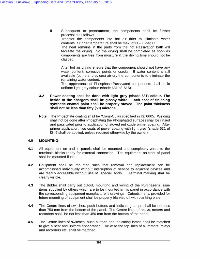
391
II Subsequent to pretreatment, the components shall be further
processed as follows. Transfer the components into hot air drier to eliminate water contents, air drier temperature shall be max. of 60-80 deg.C. The heat remains in the parts from the hot Passivation bath will facilitate the drying. So the drying shall be completed as soon as components are free from moisture & the drying time should not be clasped.
After hot air drying ensure that the component should not have any water content, corrosive points or cracks. If water content is still available (corners, crevices) air-dry the components to eliminate the remaining water content. The appearance of Phosphase-Passivated components shall be in uniform light grey colour (shade 631 of IS: 5)
3.2 Power coating shall be done with light grey (shade-631) colour. The
inside of the chargers shall be glossy white. Each coat of finishing synthetic enamel paint shall be properly stoved. The paint thickness shall not be less than fifty (50) microns.
Note: The Phosphate coating shall be ‘Class-C’, as specified in IS: 6005. Welding
shall not be done after Phosphating the Phosphated surfaces shall be rinsed and passivated prior to application of stoved red oxide primer coating. After primer application, two coats of power coating with light grey (shade 631 of IS: 5 shall be applied, unless required otherwise by the owner).
4.0 MOUNTING: 4.1 All equipment on and in panels shall be mounted and completely wired to the
terminals blocks ready for external connection. The equipment on front of panel shall be mounted flush.
4.2 Equipment shall be mounted such that removal and replacement can be
accomplished individually without interruption of service to adjacent devices and are readily accessible without use of special tools. Terminal marking shall be clearly visible.
4.3 The Bidder shall carry out cutout, mounting and wiring of the Purchaser’s issue
items supplied by others which are to be mounted in his panel in accordance with the corresponding equipment manufacturer's drawings. Cutouts if any, provided for future mounting of equipment shall be properly blanked off with blanking plate.
4.4 The Centre lines of switches, push buttons and indicating lamps shall be not less
than 750 mm from the bottom of the panel. The Centre lines of relays, meters and recorders shall be not less than 450 mm from the bottom of the panel.
4.5 The Centre lines of switches, push buttons and indicating lamps shall be matched
to give a neat and uniform appearance. Like wise the top lines of all meters, relays and recorders etc. shall be matched.
Location :: Lucknow; Uploading Date And Time ::Friday, February 13, 2015
392
4.6 No equipment shall be mounted on the doors. 4.7 All the equipment connections and cabling shall be designed and arranged to
minimise the risk of fire and damage which may be caused by fire.
5.0 PANEL INTERNAL WIRING AND OTHER ACCESSORY EQUIPMENT:
5.1 Panels shall be supplied complete with interconnecting wiring provided between all electrical devices mounted and wired in the panels and between the devices and terminal blocks for the devices to be connected to equipment outside the panels. When panels are arranged to be located adjacent to each other all inter panel wiring and connections between the panels shall be furnished and the wiring shall be carried out internally. These adjacent inter panel wiring shall be clearly indicated in the drawing furnished by the Bidder.
5.2 All wiring shall be carried out with 650V grade, single core, stranded copper
conductor wires with PVC insulation and shall be low smoke flame retardant grade and vermin and rodent proof, which shall have oxygen index not less than 29 and temperature index not less than 250 deg. C. The minimum size of the stranded copper conductor used for internal wiring shall be as follows
a) All circuits except current transformer circuits and voltage transformer
circuits meant for energy metering one of 1.5 mm sq. Copper. b) Current transformer circuits one 2.5 Sqmm copper. c) Voltage transformer circuits (for energy metering): Two of 2.5 mm sq. per
lead . The minimum No. of strands per conductor shall be three. 5.3 All internal wiring shall be securely supported, neatly arranged, readily accessible
and connected to equipment terminals and terminal blocks. Wiring gutters & troughs shall be used for this purpose.
5.4 Auxiliary bus wiring for AC and DC supplies, voltage transformer circuits,
annunciation circuits and other common services shall be provided near the top of the panels running throughout the entire length of the panels. These buses shall have a nominal cross section equivalent to a copper diameter of 6 mm and shall be suitably insulated all along their run. D.C. buses shall be divided into two sections to permit two independent supply points.
5.5 Wire termination shall be made with solder less crimping type and tinned copper
lugs which firmly grip the conductor and insulation. Insulated sleeves shall be provided on all the wire terminations. Engraved core identification plastic ferrules marked to correspond with panel wiring diagram shall be fitted at both ends of each wire. Ferrules shall fit tightly on the wire and shall not fall off when the wire is disconnected from terminal blocks.
All wires directly connected to trip circuit breaker or device shall be distinguished by the addition of red coloured unlettered ferrule. Numbers 6 and 9 shall not be included for ferrule purposes. The wire numbers shown in the wiring diagram shall be as per IS 305.
5.6 Longitudinal troughs extending throughout the full length of the panel shall be
preferred for inter panel wiring. Inter-connections to adjacent panel shall be brought out to a separate set of terminal blocks located near the slots of holes meant for taking the inter-connecting wires. Arrangements shall permit easy inter-connections
Location :: Lucknow; Uploading Date And Time ::Friday, February 13, 2015
393
to adjacent panels at site and wires for this purposes provided by Bidder shall be looped and bunched properly inside the panel.
5.7 Bidder shall be solely responsible for the completeness and correctness of the
internal wiring and for the proper functioning of the connected equipment. 6.0 TERMINAL BLOCKS:
6.1 All internal wiring to be connected to the external equipment shall terminate on terminal blocks, preferably vertically mounted on the side of each panel. Terminal blocks shall be 650 V grade and have 10 amps continuous rating, moulded piece, complete with insulated barriers, stud type terminals, washers, nuts and lock nuts. Terminal block design shall include a white fibre markings strip with clear plastic, slipon/clipon terminal covers. Markings on the terminal strips shall correspond to wire number and terminal numbers on the wiring diagrams.
6.2 Not more than 2 wires shall be connected to any terminal. Suitable supports shall be provided for the incoming cables. The terminal blocks shall be arranged to provide maximum accessibility to all conductor terminations. The terminal blocks shall be fully enclosed with easily removable covers and made of moulded, non inflammable plastic material with bases and barriers moulded integrally.
6.3 Terminal blocks for current transformer and voltage transformer secondary leads
shall be provided with test links and isolating facilities. Also current transformer secondary leads shall be provided with short circuiting and earthing facilities.
6.4 At least 20% spare terminals shall be provided on each panel and these spare
terminals shall be uniformly distributed on all terminal blocks. 6.5 In case of duplex panels separate set of terminal blocks shall be provided with
separate internal cable entries for the front and rear sections. Wiring gutters, troughs shall be provided at the top for interconnecting wiring between front and rear section of duplex panels.
6.6 Unless otherwise specified, terminal blocks shall be suitable for connecting the
following conductor's of purchaser's cables: i) All circuits expect CT and voltage circuits one 2.5 Sqmm. copper ii) All CT and PT circuits’ minimum of two of 2.5 mm sq. copper. iii) AC/DC power supply circuits one of 6 mm sq. aluminum. 6.7 There shall be a minimum clearance of 250 mm between the first row of terminal
blocks and the associated cable gland plate or panel side wall as per the terminal block mounting arrangement adopted. Also, the clearance between two rows of terminal blocks shall be a minimum of 150 mm.
6.8 Arrangement of the terminal block assemblies and the wiring channel within the
enclosure shall be such that a row of terminal blocks is run parallel and in close proximity along each side of the wiring duct to provide for convenient attachment of internal panel wiring. The side of the terminal block opposite the wiring duct shall be reserved for the purchaser's external cable connection. An adjacent terminal block shall also share this field wiring corridor. A steel strip shall be connected between adjacent terminal block rows at 450 mm intervals for support of incoming cables. All wiring shall be provided with adequate support inside the panels to hold them firmly and to enable free and flexible termination without causing strain to terminals.
Location :: Lucknow; Uploading Date And Time ::Friday, February 13, 2015
394
6.9 All number and sizes of the purchaser's multicore incoming cable will be furnished
to the Bidder after placement of the order. All necessary cable terminating accessories such as gland plates, packing glands, crimp type tinned copper lugs supporting clamps and brackets, wiring troughs and gutters etc. for purchaser's cable shall be included in the Bidder's scope of supply
7.0 NAME PLATES AND MARKINGS:
7.1 All equipment mounted on front and rear side as well as equipment mounted inside the panels shall be provided with individual name plates with equipment designation engraved. Also on the top of each panel on front as well as rear side large and bold name plates shall be provided for circuit/feeder designation. These circuit labels shall be larger than the other name plates.
7.2 All front mounted equipment shall also be provided at the rear with individual name plates engraved with tag numbers corresponding to the one shown in the panel internal wiring to facilitate easy tracing of the wiring. The name plates shall be mounted directly by the side of the respective equipment and shall not be hidden by the equipment wiring.
7.3 Name plates shall be made of non-rusting metal or 3 ply lamicoid. Name plates shall be black with white engraving lettering. The name plate inscription and size of name plates and letters shall be submitted to the Purchaser for approval.
7.4 Each instrument and meter shall be prominently marked with the quantity
measured (e.g. kV, A, MW etc.). All relays and other devices shall be clearly marked with manufacturer's name and type, serial numbers and electrical rating data.
7.5 Each switch shall bear clear inscription identifying its function e.g. 'BREAKER'
'52A', "SYNCHRONISING" etc. Similar inscription shall also be provided on each device whose function is not other wise identified. If any switch device does not bear this inscription separate name plate giving its function shall be provided for it. Switch shall also have clear inscription for each position indication e.g. "Trip-Neutral-Close", "ON-OFF", "R-Y-B-OFF" etc.
7.6 All relays and other devices shall be clearly marked with manufacturer's name,
manufacturer's type, serial number and electrical rating data. 8.0 SUPPORTING STEEL:
All necessary embedded levelling steel, sills, anchor bolts, channels and other parts for supporting and fastenings the panels and vibration damper shall be supplied by the Bidder. Embedded parts with detailed instructions shall be delivered in time to meet the schedule for insertion in the building structure.
9.0 MISCELLANEOUS ACCESSORIES: 9.1 Plug Point: 240 Volts, Single Phase, 50 Hz AC socket with switch suitable to accept
5 amps and 15 amps pin round standard plug, shall be provided in the interior of each cubicle with ON-OFF switch for connection of hand lamps.
9.2 Interior Lighting : Each panel shall be provided with a energy saving fluorescent lighting fixture rated for 240 Volts, single phase, 50Hz supply for the interior illumination of the panel during maintenance. The fittings shall be complete with
Location :: Lucknow; Uploading Date And Time ::Friday, February 13, 2015
395
switch-fuse unit and switching of the lighting shall be controlled by the respective panel door switch.
9.3 Switches and Fuses: Each panel shall be provided with necessary arrangements for receiving, distributing isolating, of DC and AC supplies for various control, signaling, lighting and space heater circuits. The incoming and sub-circuits shall be separately provided with miniature circuit breakers (MCB). Selection of the main and sub-circuit MCB ratings shall be such as to ensure selective clearance of sub-circuit faults. MCBs shall confirm to IS : 13947. Each MCB shall be provided with one potential free contact and the same shall be wired for annunciation purpose. However voltage transformer circuits for relaying and metering shall be protected by fuses. All fuses shall be HRC cartridge type conforming to IS: 13703 mounted on plug in type fuse bases. Fuse carrier base as well as MCBs shall have imprints of fuse rating and voltage.
9.4 Space Heater: Tubular space heaters of adequate capacity and suitable for connection to single phase, 240V, 50Hz supply shall be provided inside each panel to prevent condensation of moisture on the wiring and panel mounted equipment when the panel is not in operation. These shall not be mounted close to the wiring or any panel mounted equipment. Heaters shall be complete with isolating switches, HRC fuse on phase and link on the neutral of the heater supply and its switching shall be controlled by a thermostat.
9.5 Test Blocks: Switchboard type, back connected semi flush mounting type test blocks with contacts suitably rated shall be provided with links or other devices to enable insertion of a series device into the circuit without causing open circuit in the CT. secondary or to enable short circuiting of the CT. Secondary. Test block covers shall be removable from the front of the panels and shall be provided with suitable sealing arrangement to prevent unauthorized access to the test studs. If any test plugs are to be used with the test studs, 6 Nos. of each type of such test plugs shall be supplied free with the main equipments.
9.6 Other Accessories: Test link, special terminal boards and other accessories normally required for testing operation and maintenance of all relays and meters shall be furnished by the Bidder.
10.0 EARTHING: 10.1 All panels shall be equipped with an earth bus securely fixed. Location of earth bus
shall ensure no radiation interference for earth systems under various switching conditions of isolators and breakers. The material and the sizes of the bus bar shall be at least 50 x 6 mm GI flat or equivalent copper unless specified otherwise. When several panels are mounted adjoining each other, the earth bus shall be made continuous and necessary connectors and clamps for this purpose shall be included in the scope of supply of Bidder. Provision shall be made for extending the earth bus bars to future adjoining panels on either side.
10.2 Provision shall be made on each earth bus bars of the end panels for connecting Owner's earthing grid. Necessary terminal clamps and connectors for the purpose shall be included in the scope of supply of Bidder. The size of Owner's earthing grid connections will be furnished later to the Bidder. The earth wire or screens should be clearly bonded and earthed at the gland plate. The earthing scheme shall be got approved.
10.3 All metallic cases of relays, instruments and other panel mounted equipment shall be connected to the earth bus by independent copper wires of size not less than 2.5 sq.mm. The colour code of earthing wires shall be green. Earthing wire shall be connected on terminals with suitable clamp connectors and soldering shall not be permitted.
Location :: Lucknow; Uploading Date And Time ::Friday, February 13, 2015

396
10.4 Looping of earth connections which would result in loss of earth connection to
other devices when the loop is broken shall not be permitted. However, looping of earth connections between equipment to provide alternative paths to earth bus shall be provided.
10.5 VT and CT secondary neutral or common lead shall be earthed at one place only at the terminal blocks where they enter the panel. Such earthing shall be made through links so that earthing may be removed from one group without disturbing continuity of earthing system for other groups.
10.6 The detailed earthing scheme shall be submitted for approval. 11.0 INSTRUMENTS, METERS, RECORDERS & TRANSDUCERS: 11.1 All instruments, meters recorders and transducers shall be enclosed in dust
proof, moisture resistant, black finished cases and shall be suitable for tropical use. All indicating instruments and recorders shall be provided with separate individual transducers conforming to Annexure-XI and they shall be calibrated along with transducers to read directly the primary quantities. They shall be accurately adjusted and calibrated at works and shall have means of calibration check and adjustment at site. The bidder shall confirm that the instruments, recorders along with transducers and energy meters offered by them are suitable for connecting to the instrument transformers having the technical particulars given in the associated schedule of details of instrument transformers. All accessories including the test switches and test plugs, where applicable shall be furnished. Their elements shall be shock resistant and shielded from external magnetic fields.
11.2 Indicating Instruments:
a) Unless otherwise specified all electrical indicating instruments shall have circular 240 deg. scale and with a dial of 96 mm x 96 mm. They shall be suitable for flush mounting with only flanges projecting on vertical panel and back connected.
b) Instruments dial shall be with white circular scale and black pointer and with black numerals & lettering and knife edge pointers. The dial shall be free from warping, fading, and discoloring. The dial shall also be free from parallax error. Spring controlled instruments shall be provided with front of board zero adjuster, capable of being safely handled while the instrument is in service.
c) Instruments shall conform to IS:1248 and shall have accuracy class of 1.5 or better. The design of the scales shall be such that it can read to a resolution corresponding to 50% of the accuracy class index.
d) Instrument covers shall be of shadow proof design, utilising all available light. The indicating instruments shall have red marks on the dial corresponding to rated values of the associated primary equipment.
e) Ammeters and current coils of wattmeters and varmeters shall continuously withstand 120% of rated current and 10 times the rated current for 0.5 sec. Without loss of accuracy. Voltmeters and potential coils of wattmeters and varmeters shall withstand 120% of rated voltage for 0.5 seconds without loss of accuracy.
f) DC ammeters shall be provided with external shunt wherever the current exceeds 5 amps. The rated voltage drop for the shunts shall be 75 mV.
g) Synchronising Instruments shall also meet the requirements of Clause 10.5 of this section.
h) Digital bus voltage and frequency meter shall be of class 0.5 and shall have digital display of five (5) and four (4) digits respectively with display size not less than 25 mm (height).
Location :: Lucknow; Uploading Date And Time ::Friday, February 13, 2015

397
11.3 Metering Instruments: 11.3.1 Energy Meters:
Energy meters shall be static type conforming to IEC:687 and suitable for inter utility EHV bi-directional power flow and for CT/CVT connection. The static meter shall carryout measurement of active energy (both import and export) and reactive energy (both import and export) by 3-phase four wire principle suitable for balanced/unbalanced 3-phase load. The accuracy of energy measurement shall be 0.2 for active energy and 1 for reactive energy. The active and reactive energy shall be directly computed in CT & VT primary ratings and stored in four different registers of the memory of the meter as MWH(E), MHH(I), MVARH(E) and MVARH(I) along with a plus sign for export and minus sign for import. Meters shall compute the energy sentout/received from/to the station bus bar during each successive 15 minute block and store in the respective registers. Meter shall display on demand the energy sentout/received during the previous 15 minute block. Further the meter shall continuously integrate the energy readings of each register upto that time. All these readings shall be displayed on demand. Cumulative reading of each register shall be stored in non-volatile memory at the end of each hour of the day starting from 0100 hrs. These readings shall be stored for a period of 40 days before being erased. The static meter shall have a built-in clock and calendar having an accuracy of atleast 1 minute per month or better. Date/time shall be displayed on demand. The clock shall be synchronised by GPS time synchronising equipment being provided or other time signals. Each meter shall have a unique identification code provided by purchaser and shall be marked permanently on the front and also on the non-volatile memory. The voltage monitoring of all the three voltages shall be provided. The meter shall normally operate with power drawn from VT supplies. The power supply to the meter shall be healthy even with a single phase VT supply. An automatic backup shall be provided by a builtin life time battery and shall not need replacement for atleast ten years with a continuous VT interruption of atleast two years. Date and time of VT interruption and restoration shall be automatically stored in non-volatile memory. The static meter shall have an optical port at the front of the meter for data collection by a hand held device. The necessary software shall be provided to accept the data from DCD and store in memory and on a floppy diskette and also to print the same .The meter shall have means to communicate with sub-station monitoring system. The meter shall have means to test MWH accuracy and for connecting it to time-of-day tariff equipment. Pulse rate shall be 100 pulses per MWH and 100 pulses per MVARH from to separate devices.
11.4 Disturbance Recorder A. For Line
B. Deleted 11.4.1 Disturbance recorder shall be microprocessor based and shall be used to record
the graphic form of instantaneous values of voltage and current in all three phases, open delta voltage & neutral current, open or closed position of relay contacts and breakers during the system disturbances and built in feature of Line Distance relay is acceptable and shall be activated in Both Numerical Protections.
11.4.2 The Disturbance recorder shall consist of individual acquisition units, or as a part of Bay Protection Units and an Evaluation unit which is common for the entire Sub-Station.Whenever, more than one acquisition units are connected to an Evaluation unit, necessary hardware and software shall also be supplied for on line transfer of data from all acquisition units of Evaluation unit. If there are any constraints for one Evaluation unit to accept the data from number of acquisition units under the present scope, adequate number of Evaluation units shall be supplied. In case of extension of existing Sub-Station(s), one set of Evaluation unit shall be supplied for each substation where ever disturbance recorders are specified.
Location :: Lucknow; Uploading Date And Time ::Friday, February 13, 2015
398
11.4.3 Disturbance recorder shall have minimum 8 analog and 40 digital channels for
each feeder for distance protection.
11.4.4 Acquisition units shall acquire the fault data for the pre fault and post fault period and transfer them to Evaluation unit automatically to store in the hard disk. The acquisition units shall be located in the protection panels of the respective feeders.
11.4.5 The acquisition unit shall be suitable for inputs from Current Transformers with 1A rated secondary Current and Capacitive/Electromagnetic Voltage Transformers with 63.5V (phase to neutral voltage) rated secondary. Any device required for processing of input signals in order to make the signals compatible to the Disturbance recorder equipment shall form an integral part of it. However, such processing of input signals shall in no way distort it waveform.
11.4.6 The equipment shall be carefully screened, shielded, earthed and protected as may be required for its safe functioning. Also, the disturbance recorder shall have stable software, reliable hardware, simplicity of maintenance and immunity from the effects of the hostile environment of EHV switchyard which are prone to various interference signals typically from large switching transients.
11.4.7 The Evaluation unit shall consist of a desktop personal computer (including VGA colour monitor, mouse and key board) and printer. The desktop PC shall have Pentium-IV processor or better and having a clock speed 2GHz or better. The hard disk capacity of PC shall not be less than 40 GB and RAM capacity shall not be less than 256 MB.
11.4.8 Evaluation software shall be provided for the analysis and evaluation of the recorded data made available in the PC under WINDOWS environment. The Software features shall include repositioning of analog and digital signals selection and amplification of time and amplitude scales of each analog and digital channel, calculation of MAX/MIN frequency, phase difference values, recording of MAX/MIN values etc. of analog channel, group of signal to be drawn on the same axis etc. listing and numbering of all analog and digital channels and current, voltage, frequency and phase difference values at the time of fault/tripping. Also, the software should be capable of carrying out Fourier/Harmonic analysis of the current and voltage wave forms. The Disturbance recorder shall have a facility to Transfer the Analog values during pre fault, during fault and post fault and time taken for each digital values activated after fault occurred. It shall have a facility to calculate the fault locator and Transfer the data. The disturbance records shall also be available in COMTRADE format (IEEE standard – Common Format for Transient data Exchange for Power System).
11.4.9 The Evaluation unit shall be connected to the printer to obtain the graphic form of
disturbances whenever desired by the operator. 11.4.10 Disturbance recorder acquisition units shall be suitable to operate from 220V DC
as available at Sub-Station Evaluation unit along with the printer shall normally be connected to 230V, single phase AC supply. In case of failure of AC supply, Evaluation unit and printer shall be switched automatically to the station DC through Inverter of adequate capacity which shall form a part of Disturbance recorder system.
11.4.11 The acquisition unit shall have the following features. a) Facility shall exist to alarm operator in case of any internal faults in the acquisition
units such as power supply fail, processor/memory fail etc and same shall be wired to annunciation system.
b) The open delta voltage and neutral current shall be derived either through software or externally by providing necessary auxiliary transformers.
c) The acquisition unit shall be typically used to record the following digital channels:
Location :: Lucknow; Uploading Date And Time ::Friday, February 13, 2015
399
In Case of Line 1. HV MAIN CB OPEN 2. HV TIE TIE CB OPEN 3. 21 MAIN1 RELAY OPERATED 4. 21 MAIN2 RELAY OPERATED 5. 87 BUSBAR RELAY OPERATED 6. MAIN CB A/R OPERATED 7. TIE CB A/R OPERATED 8. PSB OPERATED 9. SOTF OPERATED 10. 27 O/V STG-1 OPERATED 11. 27 O/V STG-2 OPERATED 12. 51 STUB-1/2 OPERATED 13. 87HZ / LZ TEED-1/2 OPERATED 14. MAIN CB LBB OPERATED 15. TIE CB LBB OPERATED
16. DIRECT TRIP CH-1/2 RECEIVEDTRIP 17. 21M1 CARRIER RECEIVE
18. 21M2 CARRIER RECEIVE 19. 86 GR-A/B RELAY OPERATED 20. 67N DEF/TEF RLY OPERATED 21. DF/DT RELAY OPERATED
In Case of Transformer 1. HV MAIN CB OPEN 2. HV TIE TIE CB OPEN 3. LV 33 kV CB OPEN 4. 87 T1 LZ DIFF RLY OPERATED 5. 87 T2 HZ DIFF RLY OPERATED 6. HV 67 ABCN OPERATED 7. LV 67 ABCN OPERATED 8. 51 O/L RLY OPERATED 9. NDR RLY OPERATED 10. HV 86 GR-A/B RELAY OPTD 11. LV 86 GR-A/B RELAY OPTD 12. OIL TEMP HIGH TRIP 13. WNDG TEMP HV/IV/LV TRIP 14. BUCHHOLZ MAIN/OLTC TRIP 15. PRD 1/ 2 TRIP 16. AT/F NEUTRAL CURRENT TRIP
d) If offered as inbuilt feature of Line Distance Relays, it should be quoted for both Main and backup (for 100% redundancy). Similarly for Transformer 87 T1 and 87 T2,
e) In case the disturbance recorder is in-built part of Bay protection Unit, above digital
channels may be interfaced either externally or internally. f) Any digital signal can be programmed to act as trigger for the acquisition unit.
Analog channels should have programmable threshold levels for triggers and selection for over or under levels should be possible.
Location :: Lucknow; Uploading Date And Time ::Friday, February 13, 2015
400
11.4.12 The printer shall be compatible with the desktop PC and shall use Plain paper.
The print out shall contain the Feeder identity, Date and time (in hour, minute and second up to 100th of a second), identity of trigger source and Graphic form of analog and digital signals of all the channels. Ten packets of Z-fold paper (500 sheets in each packet) suitable for printer shall be supplied.
11.4.13 Each disturbance recorder shall have its own time generator. The clock of the time
generator shall be such that the drift is limited to +/- 0.5 seconds/day, if allowed to run with out synchronisation. Further, Disturbance recorder shall have facility to synchronise its time generator from Time Synchronisation Equipment having output of following types. Voltage signal : Potential free contact The recorder shall give annunciation in case of absence of synchronising pulse within a specified time. In case DR is inbuilt function of Bay Protection units (BPU) and the SAS is implementing in IEC 61850 Time Synchronization achieved through SNTP network protocol.
11.4.14 Sub-Stations where Time Synchronisation Equipment is not available, time generator of any one of the disturbance recorders can be taken as master and time generators of other disturbance recorders and Event loggers in that station shall be synchronized to follow the master.
11.4.15 The disturbance recorder shall be capable of being triggered by the following user specified quantities : (a) overvoltage and undervoltage (b) overcurrent (c) negative sequence voltage (d) zero sequence voltage (e) overfrequency or underfrequency (f) power swing
11.4.16 The transformer relay panel shall have a disturbance recording feature to record graphic form of instantaneous values of current in all three windings in 6 analogue channels for lower voltage transformers, during faults and disturbances for the pre fault and post fault period.The disturbance recorder shall have the facility to record the following external digital channel signals apart from the digital signals pertaining to differential relay. 1. 87 T2 protection operated 2. HV breaker status (Main) 3. LV breaker status ((Main) 4. Bucholz /OLTC Bucholz alarm / trip 5. WTI/OTI/PRD alarm/trip of transformer
11.4.17 Necessary hardware and software for down loading the data captured by disturbance
Recorder to the personal computer available in the substation shall be included in the scope.
11.5 Fault Locator:
i) Electronic or microprocessor based type. ii) 'On-line' type iii) Built-in display unit iv) The display shall be directly in percent of line length or kilometers without
requiring any further calculations. v) Accuracy for all types for faults and fault levels. vi) The above accuracy should not be impaired under the following conditions:
Location :: Lucknow; Uploading Date And Time ::Friday, February 13, 2015
401
a) Presence of remote end in feed
b) Predominant D.C. component in fault current c) High fault ARC resistance d) Severe PT transients e) Magnitude of line loading before occurrence of faults.
vii) Facility for remote data transmission. viii) Shall meet IEC-255 or any other equivalent internationally recognized
standards. ix) shall have mutual zero sequence compensation unit if fault locator is to be
used on double circuit line . x) Have built in supervision and testing facility. xi) Built in feature of line distance relay is acceptable provided the
requirements of above clauses are met. 12.0 RELAYS: 12.1 All relays shall conform to the requirements of IS: 3231 or other applicable
approved standards. Relays shall be suitable for flush or semi-flush mounting on the front with connections from the rear. Relays shall be rectangular in shape and shall have dust tight, dull black or egg shell black enamel painted cases with transparent cover removable from the front.
12.2 All protective relays shall be in draw out or plug-in type / modular cases with proper testing facilities. The testing facilities provided on the relays available at Manufacturer/Supplier works shall be specifically stated in the bid. Necessary test plugs shall be supplied loose and shall be included in Bidder's scope of supply. Test block and switches shall be located immediately below each relay for testing. As an alternative to test block and test plug arrangements the Bidder shall also quote alternative testing facility of protective relays by providing push button which when pressed connects the testing equipment to the relay coils and injects current in the coil and automatically disconnects the trip circuits and on operation of relay gives a signal that the equipment and the circuits are healthy. The above tests shall be carried out without short circuiting the CT secondary connections. The Owner reserves the right for accepting any one of the above two testing facilities. Unless otherwise specified all auxiliary relays and timers shall be supplied in non-draw out cases/plug in type modular cases.
12.3 All A.C. relays shall be suitable for operation at 50 Hz. A.C. Voltage operated relays shall be suitable for 110 Volts or 110//3 VT secondaries and current operated relays for 1 Amp CT secondaries as specified in this specification. DC auxiliary relays and timers shall be designed for the DC voltage specified, and shall operate satisfactorily between 80% and 110% of rated voltage. Voltage operated relays shall have adequate thermal capacity for continuous operation.
12.4 The protective relays shall be suitable for efficient and reliable operation of the protection scheme described in the specification. Necessary auxiliary relays and timers required for interlocking schemes for multiplying of contacts to suit contact duties of protective relays and monitoring of control supplies and circuits, lockout relay monitoring circuits etc. and also required for the complete protection schemes described in the specification shall be provided. All protective relays shall be provided with at least two pairs of potential free isolated output contacts. Auxiliary relays and timers shall have pairs of contacts as required to complete the scheme, contacts shall be silver faced with spring action. Relay cases shall have adequate number of terminals for making potential free external connections to the relay coils and contacts including spare contacts. Relay case size shall be so chosen as not to introduce any limitations on the use of available contacts on the relay due to in-adequacy of terminals. Paralleling of contacts, if any shall be done at the terminals on the casing of the relay.
Location :: Lucknow; Uploading Date And Time ::Friday, February 13, 2015
402
12.5 All protective relays, auxiliary relays and timers except the lock out relays and
interlocking relays specified shall be provided with self-reset type contacts. All protective relays and timers shall be provided with externally hand reset positive action operation indicators, provided with inscription, subject to Owner's approval. All protective relays which do not have built-in-hand reset operation indicators shall have additional auxiliary relays with operating indicators for this purpose. Similar separate operating indicator (auxiliary relays) shall also be provided in the trip circuits of protections located outside the board such as bucholz relays, temperature protection, fire protection etc.
12.6 Timers shall be of the electromagnetic or solid state type. Pneumatic timers are not acceptable. Short time delays in terms of milli seconds may be obtained by using copper slugs on auxiliary relays. In such case it shall be ensured that the continuous rating of the relay is not affected. Time delay in terms of milli seconds obtained by the external capacitor resistor combination is not acceptable.
12.7 No control relay which shall trip the power circuits breaker when the relay is de-energised shall be employed in the circuits. All relays shall be self reset type unless otherwise specified.
12.8 Provision shall be made for easy isolation of trip circuits of each relay for the purpose oftesting and maintenance.
12.9 All relays shall withstand a test voltage of 2.5 KV, 50 Hz, rms voltage for one second. In case of static relays the Clause 13.12 shall be applicable.
12.10 Auxiliary seal-in-units provided on the protective relays shall preferably be of shunt reinforcement type. If series relays are used the following shall be strictly ensured: a) The operating time of the series seal-in-unit shall be sufficiently shorter than
that of the trip coil or trip relay in series with which it operates to ensure definite operation of the flag indicator of the relay.
b) Seal-in-unit shall obtain adequate current for operation when one or more relays operate simultaneously. Impedance of the seal-in-unit shall be small enough to permit satisfactory operation of the trip coil on trip relays when the D.C. Supply voltage is minimum.
12.11 All protective relays and alarm relays shall be provided with one extra isolated pair of contacts wired to terminals exclusively for Owner's use.
12.12 Wherever solid state relays are used the following requirements shall be met with: a) The printed circuit cards shall be of fibreglass type and the contact shall be
gold plated. All connections with the connector pegs shall be through wire wrapping. All solder joints on the printed circuit boards shall be encapsulated or covered with varnish.
b) The components shall be "adequately rated to carry twice the normal expected loads". The resistors shall be of carbon composition or metal oxide type and the capacitors shall be plastic film or tantalum type. Stringent measures including shielding of long internal wiring should be taken to make relays immune to voltage spikes. The relays must withstand the requirements of IEC 255-4 appendix-E Class III regarding H.F. disturbance tests, IEC 255-4 regarding impulse test at 5 KV and fast transient test as per IEC 801-4. Insulation barriers shall be provided to ensure that transients present, in CT & VT connections due to extraneous sources do not cause damage to static circuits.
c) All relays shall be designed for satisfactory performance under tropical and humid conditions specified under Volume-II Annexure - C. Special mention shall be made in the technical deviations schedule of the bid for those relays, if any, that Bidder proposes to use which differ from specified requirements.
Location :: Lucknow; Uploading Date And Time ::Friday, February 13, 2015
403
d) All devices required for correct operation of each relay shall be provided by
Bidder without any extra cost. e) The Bidder shall ensure that the terminals of the contacts of the relays are
readily brought out for connections as required in the final approved scheme. The type of relay case size offered shall not create any restrictions on the availability of the contact terminals for wiring connections. All relay contacts used for remote annunciation shall be making type i.e. contacts should close to initiate annunciations.
f) DC/DC converter shall be provided in the solid state protective relay wherever necessary in order to provide a stable auxiliary supply for relay operation. Provision of DC cells in the protective relays as reliable standby power supply will however not be acceptable.
g) The solid state relays shall be stable and suitably protected against
transient/induced over voltages and noise signals. The Bidder shall state clearly in his bid, special requirements, if any, for DC input arrangement or cabling considered necessary for satisfactory operation of solid state relays quoted by him.
h) All equipment shall be of modular construction and the modules as a subunits shall be of plug in type for easy replacement. Equipment shall use solid state components and integrated circuits of latest design/techniques. The design shall permit rapid and positive recognition of defects and facilitate easy repair. Appropriate indications shall be available to enable speedy internal fault location. All components shall be readily accessible for easy disassembly and replacement.
i) All components shall be clearly and unambiguously marked and complete wiring shall be column coded and tagged wires only in flat ribbon cable will be exempt from tagging.
j) Readily accessible and clearly marked test prints shall be provided at all important points in the circuit.
k) Screw clamp terminals shall be provided for interconnection with relaying equipment. It shall be possible to test the protection channels with the equipment fully operational without rendering the equipment ineffective for genuine signals. Safety equipment such as protection cover and interlocks shall be provided. Ground terminals with isolating links shall be provided where required.
l) The Bidder shall include in the bid a list of installations where the relays quoted have been in satisfactory operation.
12.13 i) All Protection Relays shall be of Numerical relays. The following information
/ confirmation shall also be furnished in the bid. All Numerical Relays should have following minimum features. Shall be communicable on IEC61850 protocol without any protocol converter. KEMA certificate confirming interoperability, Goose messaging.. as per IEC61850 standard shall be submitted along with the Bid. Shall have one no. front RJ45 or RS 232 or USB port for Local Relay setting/ Parameterization and one No. rear FO port for connectivity to SAS over IEC61850 protocol. Should have sufficient configurable LEDs for main relay and for annunciation of backup relays & BCPUs. Should have sufficient Binary Inputs and Binary Outputs for 132 KV & 33 KV system. I/Os shall be configurable. Shall have front minimum 4 lines LCD display with Alpha numeric key pad.
Location :: Lucknow; Uploading Date And Time ::Friday, February 13, 2015
404
ii) Numerical relays are provided with built in Event / Disturbance / Fault
Recorder features. iii) The bidder shall bring out in the bid that the Numerical relays providing
different protection features / application in a single unit if any one of the application/feature goes out of service the other feature/application (s) will remain un-effected.
iv) All relays should have sufficient Binary input and output required for scheme & also have spare for future use. Any external device e.g. contactor shall not be acceptable.
13.0 AUXILIARY MONITORING RELAYS
13.1.1 Self reset auxiliary/monitoring voltages relays for specified D.C. Voltage shall be provided for use in the interlocking schemes for multiplication of contacts, and for monitoring of control supplied and circuit. Monitoring relays for lockout relay circuit shall be connected in series with lockout relay coils. The Bidder shall be responsible to ensure that the monitoring relay ratings are such that they shall positively pick-up through the breaker coils/lockout relay coils monitored, but the breakers/lockout relays shall not operate with such a connection.
13.1.2 The supply and circuit monitoring relay shall be connected to initiate an alarm upon failure of respective supply circuit. They shall preferably have reverse flags, which drop when the relay is de-energized. Otherwise, an indicating lamp shall be provided with each monitoring relay for indication of its operation.
13.2 TRIP CIRCUIT SUPERVISION RELAYS
The trip circuit shall be supervised by means of relays. The scheme shall continuously monitor the trip circuit both before closing and after closing of the breaker. The scheme shall detect (i) Failure of trip supply to trip coil of each phase (ii) Open circuit of trip circuit wiring and (iii) Failure of mechanism to complete the tripping operation. The relays shall have necessary contacts to be connected to either the alarm bell or to the annunciator available in the control panel for visual and audible indication of the failure of trip circuit and for connection to event logger. The relay shall have time delay on drop off of not less than 200 milli seconds and be provided with operation indications for each phase. Trip circuit supervision relay shall be provided for each pole of breaker for each DC source. Also 2 Nos. Indicating lamps to act in conjunction with trip circuit supervision relays for healthy trip indication of 2 sets of trip coils shall be supplied wherever called for.
Necessary external resistors for trip circuit supervision relays shall be supplied. 13.3 D.C. Supply Supervision Relay:
The relay shall be capable of monitoring the failure of d.c. supply to which it is connected. It shall have adequate potential free contacts to meet the scheme requirement. The relay shall have a 'time delay on drop-off' of not less than 100 milliseconds and be provided with operation indicator/flag.
13.4 High Speed Tripping Relay i) be instantaneous (operating time not to exceed 10 milli seconds). ii) have adequate hand resetting type contacts, preferably operated by
push-button where used in bus bar protection. The re-setting time shall be within 20 milli seconds for self-resetting relays.
iii) have necessary supervisory relays iv) be D.C. operated v) Be provided with operation indicators for each element/coil.
Location :: Lucknow; Uploading Date And Time ::Friday, February 13, 2015
405
13.5 FLAG REALAYS: They shall have
a) Hand reset flag indication b) Two elements c) Have necessary NO/NC contacts for each element/coil to meet scheme requirements and other functions like event logger, disturbance recorders etc.
13.6 DETAILED DESCRIPTION OF PROTECTIONS: The protection, auxiliary relay and timers that are required to be provided and included in the list of equipment and the detailed description of each protection and the associated equipment are described below: The setting ranges of the equipment offered, if different from the ones specified shall also be acceptable if they meet the functional requirements. The Bidder shall quote the protection equipment meeting the following requirements. The Bidder may also quote any alternative/additional protections or relays considered necessary by him for providing complete effective and reliable protection. These equipment shall be quoted separately as an alternative/addition to the main offer stating the price separately. The acceptance of this alternative/additional equipment shall lie with the Owner.
14.0 TRANSMISSION LINE PROTECTION: The Line Protection Relays are required to protect the line and clear the faults on line within shortest possible time with reliability, selectivity and full sensitivity to all type of faults on lines. The general concept is to have primary & back up protection having equal performance requirement specially in respect of time as provided by Main protection called Main and Backup Protection. The maximum fault current could be high as 31.5 KA near power station but the minimum fault current could be as low as 20% of rated current. The starting & measuring relays characteristics should work satisfactorily under these extremely varying conditions. The Protective Relays shall be suitable for use with capacitor voltage transformers having non-electronic damping and transient response as per IEC. It should be ensured that there is no additional delay in relay operating time created intentionally to have stable operation. The power supply unit if provided as an integral part of relay scheme shall be fully rated with liberal design in capacity. The DC supply for solid state relay shall be from DC/DC converters and these shall be amply & fully rated for all operating conditions in service. Insulation barriers shall be provided to ensure that transients present in CT & VT connections due to extraneous sources do not cause damage to static circuits. The circuits must comply with IEC recommendation for impulse withstand values. Adequate measures shall be taken to ensure that equipment is protected against voltage spikes occurring in Aux. DC supply. Disturbance recorder, event recorder , and distance to fault locator relay function as an integral part of line protection relay and meeting the specification requirements as per relevant clauses of these equipment shall also be acceptable. The following protections shall be provided for each of the 132 KV Transmission Lines.
14. 1 Line protection for 132 KV Lines. 21 Main: Numerical Distance Protection Scheme (with backup IDMT Earth
Fault Protection) Backup: Numerical Directional O/C & E/F Scheme Suitable for use with permissive under-reach and over reach transfer tripping. Relay shall have continuous self monitoring & diagnostic feature in both Main & Backup Distance Protection relays.
Location :: Lucknow; Uploading Date And Time ::Friday, February 13, 2015
406
Directional earth fault feature shall be available in both Main and backup protection relays. A1) Numerical protection:
i) The numerical distance protection shall have all the functional and operational requirements as given for the distance protection scheme specified hereinafter.
ii) The scheme shall have input transformation modules, analogue and digital filters, processing units A/D and D/A converters, DC supply modules etc. The sampling rate of analogue inputs, the processing speed and processing cycle of digital values shall be selected so as to achieve the operating time specified. Display on demand of various measured parameters, alarms, clock, relay identification, settings etc. during normal as well as fault conditions on individual phase basis shall be provided.
iii) The offered scheme shall have continuous self monitoring and cyclical test facilities. The clock of this system shall be synchronised through time synchronising system wherever it is available.
iv) The Bidder shall be responsible for complete engineering of the carrier aided protection scheme, and all the relays, devices etc. shall be provided.
A2) Distance Protection Scheme: i) be modular in construction.
ii) have high speed non switched distance relays for three phase systems to clear all type of line faults within the set reach of the relay. Have 6 non-switched measuring elements for each zone of protection (3 for Phase/ Phase faults and 3 for Phase /E faults).
iii) Have at least 3 starting directional impedance relays for multi-phase faults and for phase to ground faults.
iv) The relay equipment’s shall measure all type of faults without the need to switch the measuring elements to the faulty phase or phases. Zone switching to extend the reach of the measuring elements is not allowed. The reach of each zone shall be independently & individually adjustable and shall have setting in steps of 1%. Memory circuits with defined characteristics shall be provided in all three phases to ensure correct operation during close-up 3 phase faults and other adverse conditions.
v) a) Have stepped time distance characteristics and shall have at least
two directional and one non-directional independently variable time graded distance protection zones to cover two adjacent line sections. b) The reach of the relay for zones 1, 2 & 3, should be able to cover line lengths as per Clause (iii) above. The relay shall have an adjustable characteristic angle setting range of 30 deg. to 85 deg. (or) shall have independent resistance (R) and reactance (X) setting. c) Accuracy of better than or equal to 5% of set value for reach measurement in Zone-I and better than or equal to 10% of set value for Zone –II & Zone - III. d) Accuracy of better than or equal to 5 % of set value for time measurement of zone-II & zone – III.
vi) Shall ensure that this long coverage is consistent with limitations imposed by heavy loading and sound phase component of fault current. If so characterised by system requirements, it shall be possible to have polygonal/circular characteristics or offset mho
Location :: Lucknow; Uploading Date And Time ::Friday, February 13, 2015
407
type or lens shape characteristics. If the characteristics of starting relays are such that it cannot pick-up because of very low infeed, under-voltage relays may also be used as supplementary relays. Have a continuously variable ohmic range of 1-80 ohms.
vii) Have two independent continuously variable time setting range of 0-2 seconds for zone-2 and for zone-3.
viii) Be selective between internal and external faults. ix) incorporate three separate high speed trip relays for single
phase faults and a fourth high speed trip relay for multi-phase faults. Each of these shall have adequate contacts to meet the complete scheme requirement. These trip relays shall conform to Cl.14.4 of Section Technical of Volume-III but with self reset type contacts.
x) Include power swing blocking protection which shall a) Be of triple pole type .
b) Have suitable setting range to encircle the distance protection described above. c) Have a continuously adjustable time delay on pick up of setting range 0-2 seconds.
d) Block tripping during power swing conditions. e) Be of solid state type or built in numeric/static distance relay.
f) It shall be possible to select the power swing blocking in Zone 1, 2 or 3 or any combination of the zones.
xi) Include fuse failure protection which shall a) Monitor all the three fuses of P.T. and associated cable against open circuit. b) Inhibit trip circuits on operation and initiate annunciation. c) Have an operating time less than 7 milli seconds. d) Remain inoperative for system earth faults e) Be of solid state type or built in numeric/static distance relay. f) Shall have sufficient number of contacts, one for alarm and others for blocking the tripping.
xii) Provision shall also be incorporated, wherever considered necessary to install out of step tripping relays to isolate the affected system from the rest of the system.
xiii) Suitable number of potential free contacts. xiv) Have built in supervision and testing facility. xv) Include continuous DC supply supervision. xvi) Operation of the scheme shall be immune to the presence of DC
transients during fault condition in the voltage/current inputs to the relays.
xvii) The relay shall have indicators to show the phase or phases involved in a fault and the zone in which the scheme has operated.
15.0 POWER TRANSFORMER PROTECTION:
Transformer details 132KV Transformer Capacity: 20/40 MVA
15.1 Numerical Transformer Differential protection (87 T1) i) be triple pole high speed percentage biased differential type. ii) have an operating time not greater than 30 milli seconds at 5 times setting. iii) have three instantaneous high set over current units. iv) have an adjustable bias setting range of 20-50% . v) be suitable for rated current of 1 Ampere.
Location :: Lucknow; Uploading Date And Time ::Friday, February 13, 2015

408
vi) have second harmonic restraint feature and fifth harmonic by-pass/restraint
feature and also be stable under normal over fluxing conditions. Magnetising inrush proof feature shall not be achieved through any intentional time delay e.g. use of timers to block relay operation or using disc operated Relays.
vii) Incase of 132 KV Transformers it shall be suitable for three phase two winding transformer (have Two bias windings per phase).
viii) have an operating current setting of 15% or less. ix) the relay must be stable on heavy through faults. x) Include necessary separate interposing CTs for angle and ratio correction or
have internal features in the relay to take care of angle and ratio correction. In case of Numerical relays this shall be taken care i.e. interposing CTs, angle and ratio correction.
xi) be immune to magnetising in-rush current. xii) have features to provide stability under over excited conditions. xiii) shall be numerical and using conventional CTs. xiv) shall have disturbance recording feature to record graphic for instantaneous
values of current in all three ways. 15.2 Numerical Back up Directional over current and Earth Fault Protection Relay
with high set feature: I. 67 T HV (P+N)
i) Shall have three over current and one earth fault element(s) which shall be either independent or composite unit(s).
ii) Shall have necessary VT fuse fail relay for alarm purpose. iii) 3 Nos. Directional O/C relays for HV side and 3 Nos. Directional O/C relays
for IV side shall be provided. iv) Directional over current relay shall --
be triple pole type have IDMT characteristic with a definite minimum time of 3 sec. at10 times setting. have a variable setting range of 50-200% of rated current with adjustable time multiplier settings. have a characteristic angle of 45 deg., with lead feature a directional controlled, low transient over reach, high set instantaneous unit of continuously variable setting range500-2000% of rated current. Both the inverse and high set relays shall be directional. include hand reset flag indicators or LEDs per phase. Shall be numerical type.
v) Directional Earth Fault relay shall -- a) One No. Directional E/F relay for H.V. side & one no. Directional
E/F relay for I.V. side shall be provided. b) have IDMT characteristic with a definite minimum time of 3
seconds at 10times setting c) have an adjustable setting range of 20-80% of rated current with
adjustable time multiplier settings d) have a characteristic angle of 45/60 deg., lag a directional
controlled, low transient over reach, high set instantaneous unit of continuously variable setting range 200-800% of rated current. Both the inverse and high set relays shall be directional
e) include hand reset flag indicators or LEDs. f) Shall be numerical type.
Location :: Lucknow; Uploading Date And Time ::Friday, February 13, 2015
409
15.3 Transformer over load Protection Relay on 132 KV side
i) be single pole type. ii) be of definite time over current type and built in feature with differential
relay(87T1) or 67HV shall also be acceptable (alarm only). iii) have a continuously adjustable setting range of 50-200% iv) have a drop off/pick up ratio greater than 95% v) have separately adjustable time delay relays for alarm having a setting
range of 1to 10 seconds continuously. vi) Provide sufficient number of potential free contacts to cater the needs of
connection to alarm annunciation. DAS and optional trip facility to be connected by purchaser where needed.
vii) be acceptable HV T/F Over Load Alarm is inbuilt feature of 87 T1.
15.4 Master trip relay for transformer: Transformer relay panel shall be provided with two sets of master trip relays to trip the circuit breakers through the two separate D.C. sources. Operating time of master trip relay shall be less than 10 ms. The master trip relay shall be wired up to inter-trip both the H.V. and L.V. circuit breakers. The relay shall have adequate number of contacts as will be required for the scheme.
16.0 TIME SYNCHRONISATION
i) The Time synchronisation equipment shall receive the coordinated Universal Time (UTC) transmitted through Geo Positioning Satellite System (GPS) and synchronise equipments to the Indian Standard Time in a substation.
ii) Time synchronisation equipment shall include antenna, all special cables and processing equipment etc.
iii) It shall be compatible for synchronisation of Event Loggers, Disturbance recorders and SCADA at a substation through individual port or through Ethernet realised through optic fibre bus.
iv) Equipment shall operate up to the ambient temperature of 50 degree centigrade and 100% humidity.
v) The synchronisation equipment shall have 2 micro second accuracy. Equipment shall give real time corresponding to IST (taking into consideration all factors like voltage, & temperature variations, propagation & processing delays etc). including communication time for satellite link to achieve real time signal.
vi) Equipment shall meet the requirement of IEC 60255 for storage & operation. vii) The equipment shall have a periodic time correction facility of one second
periodicity. viii) Time synchronisation equipment shall be suitable to operate from 220V DC
supply available at the sub-station with voltage variation of + 10% and -15%. ix) Equipment shall have real time digital display in hour, minute, second (24
hour mode) & have a separate time display unit to be mounted on the top of control panels having display size of approx. 100 mm height.
x) The cable connecting Antenna and Time Synchronising unit should be run through HDPE pipe or GI pipe from the location of Antenna fixing to Time Synchronising panel with suitable fixtures and no provision to enter rain water and should not be affected by atmospheric conditions.
xi) The equipment shall also have real time display in hour, minute, second, mili seconds. (24 hours mode) and shall have a separate time display unit to be mounted on the top of control panels having display size of approximately 144 mm height. The equipment shall have periodic time correction facility of one second periodicity.
Location :: Lucknow; Uploading Date And Time ::Friday, February 13, 2015
410
17.0 TESTING INSTRUMENTS:
A list of all instruments and equipments recommended for testing and of the meters and those required for commissioning of C&R Panels specified other than those specified in Clause No.21.2 of this Section shall be submitted along with the Bid. The prices of individual items shall be given. The details of each equipment and instrument shall also be furnished. This will not be considered for evaluation. However purchaser reserves the right to order for the items and quantities at his discretion at the rates quoted in the bid.
18.0 LIST OF EQUIPMENTS:
The detailed Bill of Materials to be provided in the various Control, Relay & Protection panels is listed in Annexures. The detailed Bill of Materials for Mandatory spares are also given. The Bidder shall give a complete list of equipment provided in each panel as called for in Schedule-G, Schedule of Bill of Materials. Unit price of all equipment as listed in separate Annexure shall also be furnished along with the bid. The Bidder shall clearly state any additional equipment found necessary to give a complete and comprehensive offer. He shall however substantiate his reasons for such additional equipment in his bid proposal.
19.0 QUALITY ASSURANCE, INSPECTION AND TESTING:
i) The Bidder shall finalise with UPPTCL the quality plan for manufacturing activities in UPPTCL format within 60days of Letter of Award, along with the total list of numeric, static and electromagnetic relays covered by the QP.
ii) One control copy of quality manual will be submitted within one month of Letter of Award.
iii) Bidder shall submit the Quality Plan for Bought Out items/imported items etc. in UPPTCL format.
iv) UPPTCL reserves the right to carry out Quality Audit on quality management & manufacturing systems & procedures etc.
v) Bidder shall furnish the QA document package in duplicate as per general terms & condition which shall include but not be limited to following: a) Details of Inspection/Tests/Checks carried out as per agreed QP for
main equipment. b) Routine test & type test on all associated equipment including
disturbance recorder & event recorders, meters, indicating instruments & cables etc. as per relevant Indian Standards/IEC Standard.
20.0 TESTS:
The equipment offered shall be fully type tested as per the relevant standards. Type testing of the relays shall be carried out based on general guide lines specified in CIGRE committee 34 report on simulator/Network Analyser /PTL for all relays offered including disturbance recorder, fault locator and event logger shall meet fast transmit level-III as per IEC-255-22-4 & IEC-1000. The control and relay panels shall be completely assembled and subjected to the various type and routine and acceptance tests as per the relevant standards and respective equipment sections in the presence of the purchaser's representative if desired by the purchaser. The Bidder shall, in his proposal, specifically state the details of testing facilities available at his own at his principals works.
Location :: Lucknow; Uploading Date And Time ::Friday, February 13, 2015
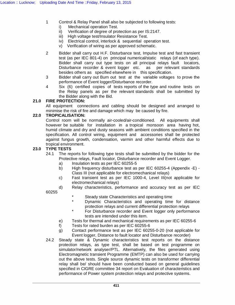
411
1 Control & Relay Panel shall also be subjected to following tests:
i) Mechanical operation Test. ii) Verification of degree of protection as per IS:2147. iii) High voltage test/Insulator Resistance Test. iv) Electrical control, interlock & sequential operation test. v) Verification of wiring as per approved schematic.
2 Bidder shall carry out H.F. Disturbance test, Impulse test and fast transient test (as per IEC 801-4) on principal numerical/static relays (of each type). Bidder shall carry out type tests on all principal relays fault locators, Disturbance recorder & event logger etc. as per relevant standards besides others as specified elsewhere in this specification.
3 Bidder shall carry out Burn out test at the variable voltages to prove the performance of Event logger/Disturbance recorder.
4 Six (6) certified copies of tests reports of the type and routine tests on the Relay panels as per the relevant standards shall be submitted by the Bidder along with the Bid.
21.0 FIRE PROTECTION: All equipment connections and cabling should be designed and arranged to minimise the risk of fire and damage which may be caused by fire.
22.0 TROPICALISATION: Control room will be normally air-cooled/air-conditioned. All equipments shall however be suitable for installation in a tropical monsoon area having hot, humid climate and dry and dusty seasons with ambient conditions specified in the specification. All control wiring, equipment and accessories shall be protected against fungus growth, condensation, varmin and other harmful effects due to tropical environment.
23.0 TYPE TESTS 24.1 The reports for following type tests shall be submitted by the bidder for the
Protective relays, Fault locator, Disturbance recorder and Event Logger. a) Insulation tests as per IEC 60255-5 b) High frequency disturbance test as per IEC 60255-4 (Appendix -E) -
Class III (not applicable for electromechanical relays) c) Fast transient test as per IEC 1000-4, Level III(not applicable for
electromechanical relays) d) Relay characteristics, performance and accuracy test as per IEC
60255 * Steady state Characteristics and operating time * Dynamic Characteristics and operating time for distance
protection relays and current differential protection relays * For Disturbance recorder and Event logger only performance
tests are intended under this item. e) Tests for thermal and mechanical requirements as per IEC 60255-6 f) Tests for rated burden as per IEC 60255-6 g) Contact performance test as per IEC 60255-0-20 (not applicable for
Event logger, Distance to fault locator and Disturbance recorder) 24.2 Steady state & Dynamic characteristics test reports on the distance
protection relays, as type test, shall be based on test programme on simulator/network analyser/PTL. Alternatively, the files generated using Electromagnetic transient Programme (EMTP) can also be used for carrying out the above tests. Single source dynamic tests on transformer differential relay shall be/ should have been conducted based on general guidelines specified in CIGRE committee 34 report on Evaluation of characteristics and performance of Power system protection relays and protective systems.
Location :: Lucknow; Uploading Date And Time ::Friday, February 13, 2015
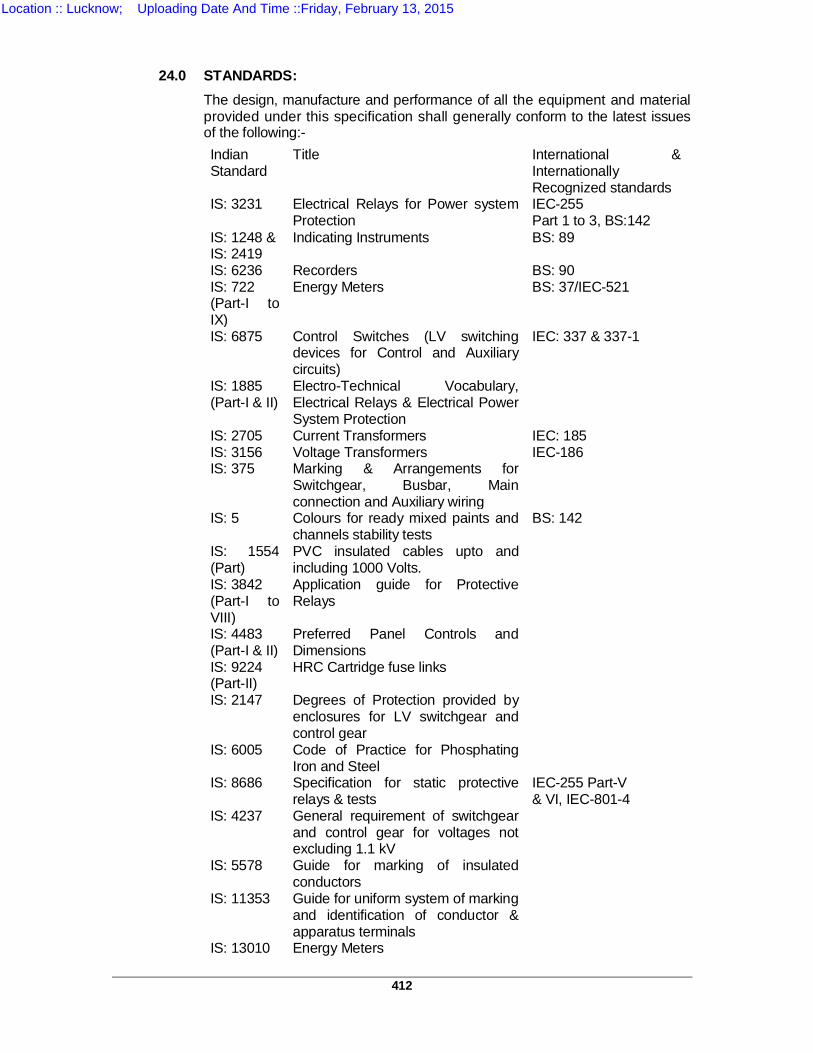
412
24.0 STANDARDS:
The design, manufacture and performance of all the equipment and material provided under this specification shall generally conform to the latest issues of the following:- Indian Standard
Title International & Internationally Recognized standards
IS: 3231 Electrical Relays for Power system Protection
IEC-255 Part 1 to 3, BS:142
IS: 1248 & IS: 2419
Indicating Instruments BS: 89
IS: 6236 Recorders BS: 90 IS: 722 (Part-I to IX)
Energy Meters BS: 37/IEC-521
IS: 6875 Control Switches (LV switching devices for Control and Auxiliary circuits)
IEC: 337 & 337-1
IS: 1885 (Part-I & II)
Electro-Technical Vocabulary, Electrical Relays & Electrical Power System Protection
IS: 2705 Current Transformers IEC: 185 IS: 3156 Voltage Transformers IEC-186 IS: 375 Marking & Arrangements for
Switchgear, Busbar, Main connection and Auxiliary wiring
IS: 5 Colours for ready mixed paints and channels stability tests
BS: 142
IS: 1554 (Part)
PVC insulated cables upto and including 1000 Volts.
IS: 3842 (Part-I to VIII)
Application guide for Protective Relays
IS: 4483 (Part-I & II)
Preferred Panel Controls and Dimensions
IS: 9224 (Part-II)
HRC Cartridge fuse links
IS: 2147 Degrees of Protection provided by enclosures for LV switchgear and control gear
IS: 6005 Code of Practice for Phosphating Iron and Steel
IS: 8686 Specification for static protective relays & tests
IEC-255 Part-V & VI, IEC-801-4
IS: 4237 General requirement of switchgear and control gear for voltages not excluding 1.1 kV
IS: 5578 Guide for marking of insulated conductors
IS: 11353 Guide for uniform system of marking and identification of conductor & apparatus terminals
IS: 13010 Energy Meters
Location :: Lucknow; Uploading Date And Time ::Friday, February 13, 2015
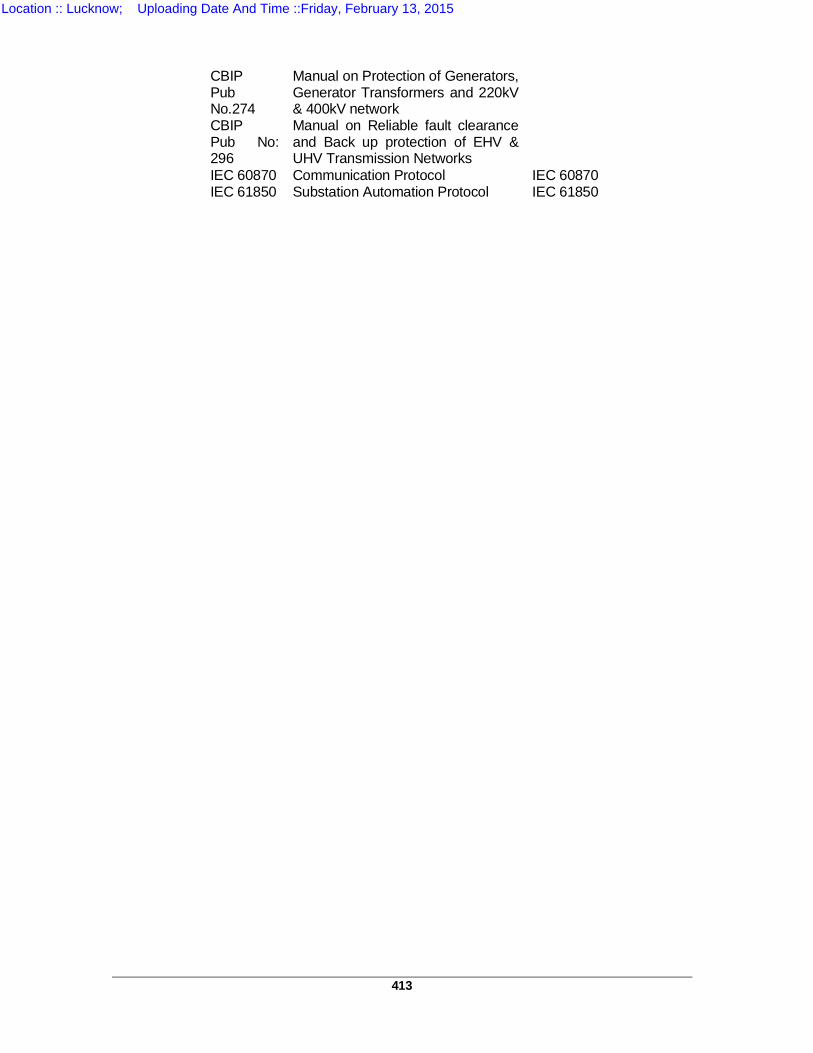
413
CBIP Pub No.274
Manual on Protection of Generators, Generator Transformers and 220kV & 400kV network
CBIP Pub No: 296
Manual on Reliable fault clearance and Back up protection of EHV & UHV Transmission Networks
IEC 60870 Communication Protocol IEC 60870 IEC 61850 Substation Automation Protocol IEC 61850
Location :: Lucknow; Uploading Date And Time ::Friday, February 13, 2015
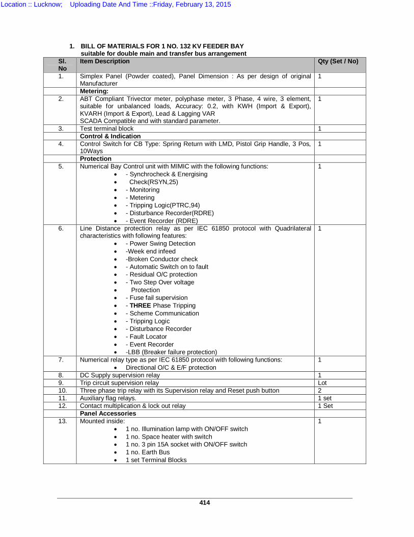
414
1. BILL OF MATERIALS FOR 1 NO. 132 KV FEEDER BAY suitable for double main and transfer bus arrangement
Sl. No
Item Description Qty (Set / No)
1. Simplex Panel (Powder coated), Panel Dimension : As per design of original Manufacturer
1
Metering: 2. ABT Compliant Trivector meter, polyphase meter, 3 Phase, 4 wire, 3 element,
suitable for unbalanced loads, Accuracy: 0.2, with KWH (Import & Export), KVARH (Import & Export), Lead & Lagging VAR SCADA Compatible and with standard parameter.
1
3. Test terminal block 1 Control & Indication
4. Control Switch for CB Type: Spring Return with LMD, Pistol Grip Handle, 3 Pos, 10Ways
1
Protection 5. Numerical Bay Control unit with MIMIC with the following functions:
- Synchrocheck & Energising Check(RSYN,25) - Monitoring - Metering - Tripping Logic(PTRC,94) - Disturbance Recorder(RDRE) - Event Recorder (RDRE)
1
6. Line Distance protection relay as per IEC 61850 protocol with Quadrilateral characteristics with following features:
- Power Swing Detection -Week end infeed -Broken Conductor check - Automatic Switch on to fault - Residual O/C protection - Two Step Over voltage Protection - Fuse fail supervision - THREE Phase Tripping - Scheme Communication - Tripping Logic - Disturbance Recorder - Fault Locator - Event Recorder -LBB (Breaker failure protection)
1
7. Numerical relay type as per IEC 61850 protocol with following functions: Directional O/C & E/F protection
1
8. DC Supply supervision relay 1 9. Trip circuit supervision relay Lot 10. Three phase trip relay with its Supervision relay and Reset push button 2 11. Auxiliary flag relays. 1 set 12. Contact multiplication & lock out relay 1 Set
Panel Accessories 13. Mounted inside:
1 no. Illumination lamp with ON/OFF switch 1 no. Space heater with switch 1 no. 3 pin 15A socket with ON/OFF switch 1 no. Earth Bus 1 set Terminal Blocks
1
Location :: Lucknow; Uploading Date And Time ::Friday, February 13, 2015
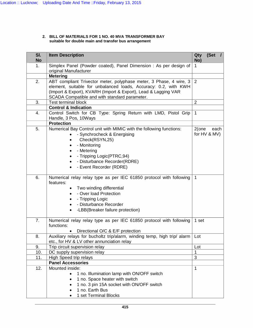
415
2. BILL OF MATERIALS FOR 1 NO. 40 MVA TRANSFORMER BAY suitable for double main and transfer bus arrangement
Sl. No
Item Description Qty (Set / No)
1. Simplex Panel (Powder coated), Panel Dimension : As per design of original Manufacturer
1
Metering 2. ABT compliant Trivector meter, polyphase meter, 3 Phase, 4 wire, 3
element, suitable for unbalanced loads, Accuracy: 0.2, with KWH (Import & Export), KVARH (Import & Export), Lead & Lagging VAR SCADA Compatible and with standard parameter.
2
3. Test terminal block 2 Control & Indication
4. Control Switch for CB Type: Spring Return with LMD, Pistol Grip Handle, 3 Pos, 10Ways
1
Protection 5. Numerical Bay Control unit with MIMIC with the following functions:
- Synchrocheck & Energising Check(RSYN,25) - Monitoring - Metering - Tripping Logic(PTRC,94) - Disturbance Recorder(RDRE) - Event Recorder (RDRE)
2(one each for HV & MV)
6. Numerical relay relay type as per IEC 61850 protocol with following features:
Two winding differential - Over load Protection - Tripping Logic - Disturbance Recorder -LBB(Breaker failure protection)
1
7. Numerical relay relay type as per IEC 61850 protocol with following functions:
Directional O/C & E/F protection
1 set
8. Auxiliary relays for bucholtz trip/alarm, winding temp, high trip/ alarm etc., for HV & LV other annunciation relay
Lot
9. Trip circuit supervision relay Lot 10. DC supply supervision relay 1 11. High Speed trip relays 3
Panel Accessories 12. Mounted inside:
1 no. Illumination lamp with ON/OFF switch 1 no. Space heater with switch 1 no. 3 pin 15A socket with ON/OFF switch 1 no. Earth Bus 1 set Terminal Blocks
1
Location :: Lucknow; Uploading Date And Time ::Friday, February 13, 2015
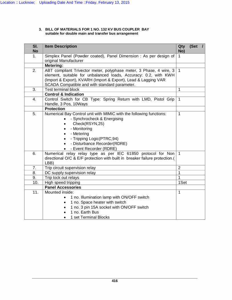
416
3. BILL OF MATERIALS FOR 1 NO. 132 KV BUS COUPLER BAY suitable for double main and transfer bus arrangement
Sl. No
Item Description Qty (Set / No)
1. Simplex Panel (Powder coated), Panel Dimension : As per design of original Manufacturer
1
Metering: 2. ABT compliant Trivector meter, polyphase meter, 3 Phase, 4 wire, 3
element, suitable for unbalanced loads, Accuracy: 0.2, with KWH (Import & Export), KVARH (Import & Export), Lead & Lagging VAR SCADA Compatible and with standard parameter.
1
3. Test terminal block 1 Control & Indication
4. Control Switch for CB Type: Spring Return with LMD, Pistol Grip Handle, 3 Pos, 10Ways
1
Protection 5. Numerical Bay Control unit with MIMIC with the following functions:
- Synchrocheck & Energising Check(RSYN,25) - Monitoring - Metering - Tripping Logic(PTRC,94) - Disturbance Recorder(RDRE) - Event Recorder (RDRE)
1
6. Numerical relay relay type as per IEC 61850 protocol for Non directional O/C & E/F protection with built in breaker failure protection.( LBB)
1
7. Trip circuit supervision relay 2 8. DC supply supervision relay 1 9. Trip lock out relays 1 10. High speed tripping 1Set Panel Accessories 11. Mounted inside:
1 no. Illumination lamp with ON/OFF switch 1 no. Space heater with switch 1 no. 3 pin 15A socket with ON/OFF switch 1 no. Earth Bus 1 set Terminal Blocks
1
Location :: Lucknow; Uploading Date And Time ::Friday, February 13, 2015
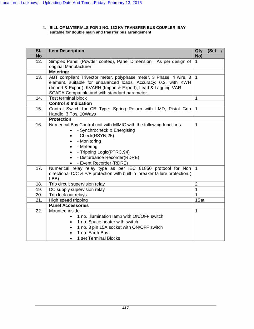
417
4. BILL OF MATERIALS FOR 1 NO. 132 KV TRANSFER BUS COUPLER BAY suitable for double main and transfer bus arrangement
Sl. No
Item Description Qty (Set / No)
12. Simplex Panel (Powder coated), Panel Dimension : As per design of original Manufacturer
1
Metering: 13. ABT compliant Trivector meter, polyphase meter, 3 Phase, 4 wire, 3
element, suitable for unbalanced loads, Accuracy: 0.2, with KWH (Import & Export), KVARH (Import & Export), Lead & Lagging VAR SCADA Compatible and with standard parameter.
1
14. Test terminal block 1 Control & Indication
15. Control Switch for CB Type: Spring Return with LMD, Pistol Grip Handle, 3 Pos, 10Ways
1
Protection 16. Numerical Bay Control unit with MIMIC with the following functions:
- Synchrocheck & Energising Check(RSYN,25) - Monitoring - Metering - Tripping Logic(PTRC,94) - Disturbance Recorder(RDRE) - Event Recorder (RDRE)
1
17. Numerical relay relay type as per IEC 61850 protocol for Non directional O/C & E/F protection with built in breaker failure protection.( LBB)
1
18. Trip circuit supervision relay 2 19. DC supply supervision relay 1 20. Trip lock out relays 1 21. High speed tripping 1Set Panel Accessories 22. Mounted inside:
1 no. Illumination lamp with ON/OFF switch 1 no. Space heater with switch 1 no. 3 pin 15A socket with ON/OFF switch 1 no. Earth Bus 1 set Terminal Blocks
1
Location :: Lucknow; Uploading Date And Time ::Friday, February 13, 2015
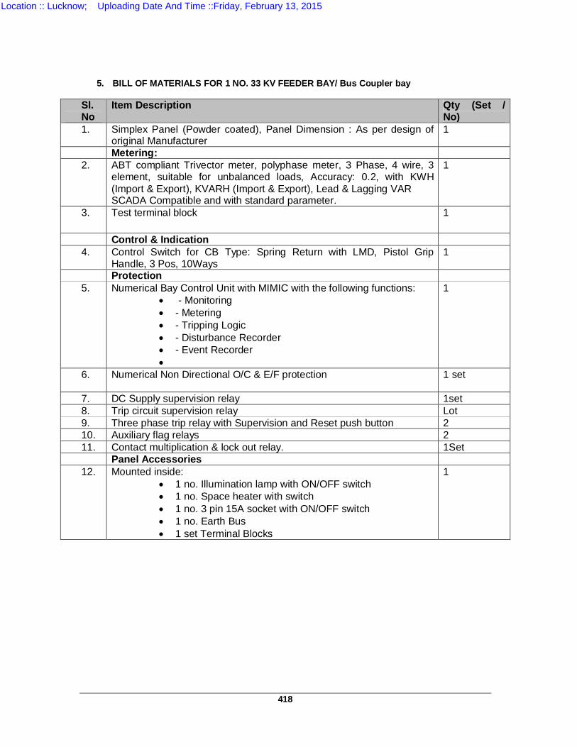
418
5. BILL OF MATERIALS FOR 1 NO. 33 KV FEEDER BAY/ Bus Coupler bay Sl. No
Item Description Qty (Set / No)
1. Simplex Panel (Powder coated), Panel Dimension : As per design of original Manufacturer
1
Metering: 2. ABT compliant Trivector meter, polyphase meter, 3 Phase, 4 wire, 3
element, suitable for unbalanced loads, Accuracy: 0.2, with KWH (Import & Export), KVARH (Import & Export), Lead & Lagging VAR SCADA Compatible and with standard parameter.
1
3. Test terminal block 1
Control & Indication 4. Control Switch for CB Type: Spring Return with LMD, Pistol Grip
Handle, 3 Pos, 10Ways 1
Protection 5. Numerical Bay Control Unit with MIMIC with the following functions:
- Monitoring - Metering - Tripping Logic - Disturbance Recorder - Event Recorder
1
6. Numerical Non Directional O/C & E/F protection
1 set
7. DC Supply supervision relay 1set 8. Trip circuit supervision relay Lot 9. Three phase trip relay with Supervision and Reset push button 2 10. Auxiliary flag relays 2 11. Contact multiplication & lock out relay. 1Set
Panel Accessories 12. Mounted inside:
1 no. Illumination lamp with ON/OFF switch 1 no. Space heater with switch 1 no. 3 pin 15A socket with ON/OFF switch 1 no. Earth Bus 1 set Terminal Blocks
1
Location :: Lucknow; Uploading Date And Time ::Friday, February 13, 2015
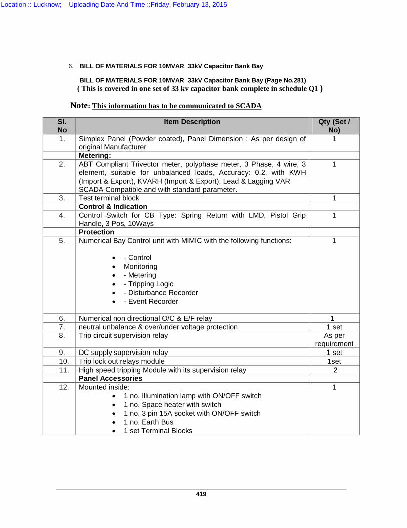
419
6. BILL OF MATERIALS FOR 10MVAR 33kV Capacitor Bank Bay
BILL OF MATERIALS FOR 10MVAR 33kV Capacitor Bank Bay (Page No.281)
( This is covered in one set of 33 kv capacitor bank complete in schedule Q1 ) Note: This information has to be communicated to SCADA Sl. No
Item Description Qty (Set / No)
1. Simplex Panel (Powder coated), Panel Dimension : As per design of original Manufacturer
1
Metering: 2. ABT Compliant Trivector meter, polyphase meter, 3 Phase, 4 wire, 3
element, suitable for unbalanced loads, Accuracy: 0.2, with KWH (Import & Export), KVARH (Import & Export), Lead & Lagging VAR SCADA Compatible and with standard parameter.
1
3. Test terminal block 1 Control & Indication 4. Control Switch for CB Type: Spring Return with LMD, Pistol Grip
Handle, 3 Pos, 10Ways 1
Protection 5. Numerical Bay Control unit with MIMIC with the following functions:
- Control Monitoring - Metering - Tripping Logic - Disturbance Recorder - Event Recorder
1
6. Numerical non directional O/C & E/F relay 1 7. neutral unbalance & over/under voltage protection 1 set 8. Trip circuit supervision relay As per
requirement 9. DC supply supervision relay 1 set 10. Trip lock out relays module 1set 11. High speed tripping Module with its supervision relay 2 Panel Accessories 12. Mounted inside:
1 no. Illumination lamp with ON/OFF switch 1 no. Space heater with switch 1 no. 3 pin 15A socket with ON/OFF switch 1 no. Earth Bus 1 set Terminal Blocks
1
Location :: Lucknow; Uploading Date And Time ::Friday, February 13, 2015
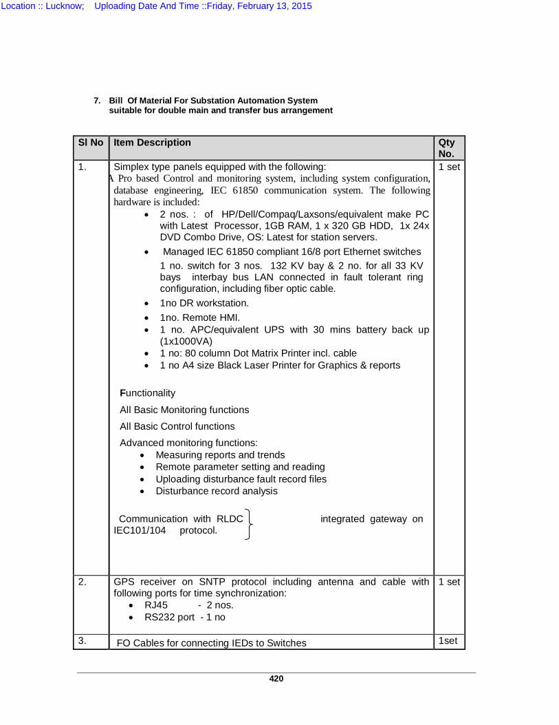
420
7. Bill Of Material For Substation Automation System suitable for double main and transfer bus arrangement
Sl No Item Description Qty No.
1. Simplex type panels equipped with the following: icro SCADA Pro based Control and monitoring system, including system configuration,
database engineering, IEC 61850 communication system. The following hardware is included:
2 nos. : of HP/Dell/Compaq/Laxsons/equivalent make PC with Latest Processor, 1GB RAM, 1 x 320 GB HDD, 1x 24x DVD Combo Drive, OS: Latest for station servers.
Managed IEC 61850 compliant 16/8 port Ethernet switches 1 no. switch for 3 nos. 132 KV bay & 2 no. for all 33 KV bays interbay bus LAN connected in fault tolerant ring configuration, including fiber optic cable.
1no DR workstation. 1no. Remote HMI. 1 no. APC/equivalent UPS with 30 mins battery back up
(1x1000VA) 1 no: 80 column Dot Matrix Printer incl. cable 1 no A4 size Black Laser Printer for Graphics & reports
Functionality
All Basic Monitoring functions All Basic Control functions Advanced monitoring functions:
Measuring reports and trends Remote parameter setting and reading Uploading disturbance fault record files Disturbance record analysis
Communication with RLDC integrated gateway on IEC101/104 protocol.
1 set
2. GPS receiver on SNTP protocol including antenna and cable with following ports for time synchronization:
RJ45 - 2 nos. RS232 port - 1 no
1 set
3. FO Cables for connecting IEDs to Switches 1set
Location :: Lucknow; Uploading Date And Time ::Friday, February 13, 2015
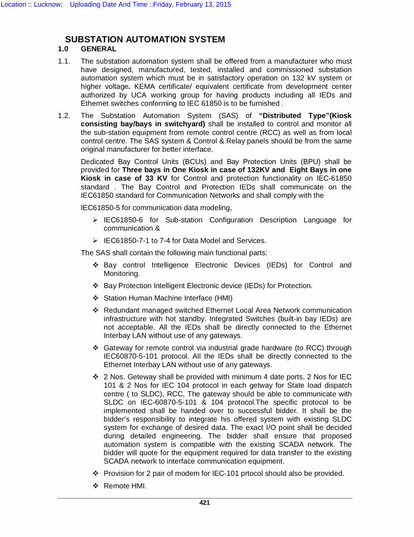
421
SUBSTATION AUTOMATION SYSTEM 1.0 GENERAL 1.1. The substation automation system shall be offered from a manufacturer who must
have designed, manufactured, tested, installed and commissioned substation automation system which must be in satisfactory operation on 132 kV system or higher voltage. KEMA certificate/ equivalent certificate from development center authorized by UCA working group for having products including all IEDs and Ethernet switches conforming to IEC 61850 is to be furnished .
1.2. The Substation Automation System (SAS) of “Distributed Type”(Kiosk consisting bay/bays in switchyard) shall be installed to control and monitor all the sub-station equipment from remote control centre (RCC) as well as from local control centre. The SAS system & Control & Relay panels should be from the same original manufacturer for better interface.
Dedicated Bay Control Units (BCUs) and Bay Protection Units (BPU) shall be provided for Three bays in One Kiosk in case of 132KV and Eight Bays in one Kiosk in case of 33 KV for Control and protection functionality on IEC-61850 standard . The Bay Control and Protection IEDs shall communicate on the IEC61850 standard for Communication Networks and shall comply with the
IEC61850-5 for communication data modeling, IEC61850-6 for Sub-station Configuration Description Language for
communication &
IEC61850-7-1 to 7-4 for Data Model and Services. The SAS shall contain the following main functional parts: Bay control Intelligence Electronic Devices (IEDs) for Control and
Monitoring. Bay Protection Intelligent Electronic device (IEDs) for Protection.
Station Human Machine Interface (HMI) Redundant managed switched Ethernet Local Area Network communication
infrastructure with hot standby. Integrated Switches (built-in bay IEDs) are not acceptable. All the IEDs shall be directly connected to the Ethernet Interbay LAN without use of any gateways.
Gateway for remote control via industrial grade hardware (to RCC) through IEC60870-5-101 protocol. All the IEDs shall be directly connected to the Ethernet Interbay LAN without use of any gateways.
2 Nos. Geteway shall be provided with minimum 4 date ports. 2 Nos for IEC 101 & 2 Nos for IEC 104 protocol in each getway for State load dispatch centre ( to SLDC), RCC, The gateway should be able to communicate with SLDC on IEC-60870-5-101 & 104 protocol.The specific protocol to be implemented shall be handed over to successful bidder. It shall be the bidder’s responsibility to integrate his offered system with existing SLDC system for exchange of desired data. The exact I/O point shall be decided during detailed engineering. The bidder shall ensure that proposed automation system is compatible with the existing SCADA network. The bidder will quote for the equipment required for data transfer to the existing SCADA network to interface communication equipment.
Provision for 2 pair of modem for IEC-101 prtocol should also be provided.
Remote HMI.
Location :: Lucknow; Uploading Date And Time ::Friday, February 13, 2015
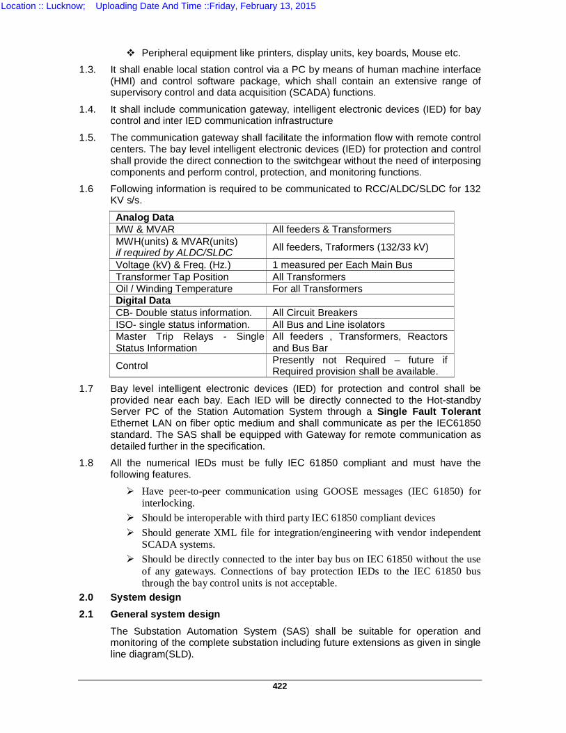
422
Peripheral equipment like printers, display units, key boards, Mouse etc.
1.3. It shall enable local station control via a PC by means of human machine interface (HMI) and control software package, which shall contain an extensive range of supervisory control and data acquisition (SCADA) functions.
1.4. It shall include communication gateway, intelligent electronic devices (IED) for bay control and inter IED communication infrastructure
1.5. The communication gateway shall facilitate the information flow with remote control centers. The bay level intelligent electronic devices (IED) for protection and control shall provide the direct connection to the switchgear without the need of interposing components and perform control, protection, and monitoring functions.
1.6 Following information is required to be communicated to RCC/ALDC/SLDC for 132 KV s/s.
Analog Data MW & MVAR All feeders & Transformers MWH(units) & MVAR(units) if required by ALDC/SLDC All feeders, Traformers (132/33 kV)
Voltage (kV) & Freq. (Hz.) 1 measured per Each Main Bus Transformer Tap Position All Transformers Oil / Winding Temperature For all Transformers Digital Data CB- Double status information. All Circuit Breakers ISO- single status information. All Bus and Line isolators Master Trip Relays - Single Status Information
All feeders , Transformers, Reactors and Bus Bar
Control Presently not Required – future if Required provision shall be available.
1.7 Bay level intelligent electronic devices (IED) for protection and control shall be provided near each bay. Each IED will be directly connected to the Hot-standby Server PC of the Station Automation System through a Single Fault Tolerant Ethernet LAN on fiber optic medium and shall communicate as per the IEC61850 standard. The SAS shall be equipped with Gateway for remote communication as detailed further in the specification.
1.8 All the numerical IEDs must be fully IEC 61850 compliant and must have the following features.
Have peer-to-peer communication using GOOSE messages (IEC 61850) for interlocking.
Should be interoperable with third party IEC 61850 compliant devices Should generate XML file for integration/engineering with vendor independent
SCADA systems. Should be directly connected to the inter bay bus on IEC 61850 without the use
of any gateways. Connections of bay protection IEDs to the IEC 61850 bus through the bay control units is not acceptable.
2.0 System design 2.1 General system design
The Substation Automation System (SAS) shall be suitable for operation and monitoring of the complete substation including future extensions as given in single line diagram(SLD).
Location :: Lucknow; Uploading Date And Time ::Friday, February 13, 2015
423
The systems shall be of the state-of-the art suitable based on IEC61850 under electrical environment present in Extra high voltage substations, follow the latest engineering practice, ensure long-term compatibility requirements and continuity of equipment supply and the safety of the operating staff. The offered SAS shall support remote control and monitoring from Remote Control centers via gateways.
The system shall be designed such that personnel without any background knowledge in Microprocessor-based technology are able to operate the system. The operator interface shall be intuitive such that operating personnel shall be able to operate the system easily after having received some basic training. The system shall incorporate the control, monitoring and protection functions specified, self-monitoring, signaling and testing facilities, measuring as well as memory functions, event recording and evaluation of disturbance records. Maintenance, modification or extension of components may not cause a shutdown of the whole substation automation system. Self-monitoring of components, modules and communication shall be incorporated to increase the availability and the reliability of the equipment and minimize maintenance. Bidder shall offer the Bay level unit (a bay comprises of one circuit breaker and associated disconnector, earth switches and instrument transformer), bay mimic along with relay and protection panels housed in air-conditioned Kiosks/Portable Relay Rooms suitably located in switchyard and Station HMI in Control Room building for overall optimization in respect of cabling and control room building. Ethernet Topology The Ethernet communication infrastructure to ensure a certain level of quality, performance and availability at least the following described criteria’s have to be fulfilled concerning the Ethernet switches and the topology. Ethernet Switches Ethernet switches that fulfill the hardened requirements concerning temperature, EMC, power supply (110 V DC from the Station Battery) and complying to 61850 part 3 of the specification suitable to be installed in substations shall be provided, i.e. the same data as common for numerical protection. The use of Ethernet Hubs is not permitted as they do not provide collision free transmission. The switches shall support priority tagging and open standards for ring management like fast scanning tree to ensure that e.g. for later system extension utility has not to rely on one switch supplier only. External switches are preferred as they have the advantage that there is no interruption or reconfiguration of the Ethernet ring if one or several bay devices are taken out of service.
2.2 System architecture The SAS shall be based on a decentralized architecture and on a concept of bay-oriented, distributed intelligence. Functions shall be decentralized, object-oriented and located as close as possible to the process. The main process information of the station shall be stored in distributed databases. The typical SAS architecture shall be structured in two levels, i.e. in a station and a bay level.
Location :: Lucknow; Uploading Date And Time ::Friday, February 13, 2015
424
At bay level, the IEDs shall provide all bay level functions regarding control, monitoring and protection, inputs for status indication and outputs for commands. The IEDs should be directly connected to the switchgear without any need for additional interposition or transducers. But incase of Circuit Breaker SF6 Gas Pressure, Operating Mechanism Pressure (i.e. Air/ Pneumatic, Hydraulic and SF6 Pressures), if SF6 CTs are Utilizing the Pressure of SF6 Gas, Transformer / Reactor Oil/ Winding temperatures, OLTC Tap Position & Operation (not AVR) can be interfaced with BCU or any Other device interface through Transducers. These parameters shall appear in Substation Automation System at Local and RCC and should be monitored regularly. Each bay control IED shall be independent from each other and its functioning shall not be affected by any fault occurring in any of the other bay control units of the station. The data exchange between the electronic devices on bay and station level shall take place via the communication infrastructure. This shall be realized using fiber optic cables, thereby guaranteeing disturbance free communication. The fiber optic cables shall be run in G.I conduit pipes. Data exchange is to be realized using IEC 61850 protocol with a redundant managed switched Ethernet communication infrastructure.
The communication shall be made in 1+1 mode, excluding the links between individual bay IEDs to switch, such that failure of one set of fiber shall not affect the normal operation of the SAS. However it shall be alarmed in SAS. Each fibre optic cable shall have four (4) spare fibres. At station level, the entire station shall be controlled and supervised from the station HMI. It shall also be possible to control and monitor the bay from the bay level equipment at all times.
Clear control priorities shall prevent operation of a single switch at the same time from more than one of the various control levels, i.e. RCC, station HMI, bay level or apparatus level. The priority shall always be on the lowest enabled control level. The station level contains the station-oriented functions, which cannot be realised at bay level, e.g. alarm list or event list related to the entire substation, gateway for the communication with remote control centers. The GPS time synchronizing signal (as specified in the section relay & protection) for the synchronization of the entire system shall be provided. The SAS shall contain the functional parts as described in para 1.2 above.
2.3 FUNCTIONAL REQUIREMENTS The high-voltage apparatus within the station shall be operated from different places: Remote control centres Station HMI.
Local Bay controller IED (in the bays) Operation shall be possible by only one operator at a time. The operation shall depend on the conditions of other functions, such as interlocking, synchrocheck, etc. (see description in ”Bay level control functions”).
Location :: Lucknow; Uploading Date And Time ::Friday, February 13, 2015
425
2.3.1 Select-before-execute For security reasons the command is always to be given in two stages: selection of the object and command for operation under all mode of operation except emergency operation. Final execution shall take place only when selection and command are actuated.
2.3.2 Command supervision Bay/station interlocking and blocking Software Interlocking is to be provided to ensure that inadvertent incorrect operation of switchgear causing damage and accidents in case of false operation does not take place. In addition to software interlocking hardwired interlocking are to be provided for:
(a) Bus Earth switch Interlocking (b) Transfer Bus interlocking (if applicable) It shall be a simple layout, easy to test and simple to handle when upgrading the station with future bays. For software interlocking the bidder shall describe the scenario while an IED of another bay is switched off or fails.
A software interlock override function shall be provided which can be enabled to bypass the interlocking function.
2.3.3 Run Time Command cancellation Command execution timer (configurable) must be available for each control level connection. If the control action is not completed within a specified time, the command should get cancelled.
2.3.4 Self-supervision Continuous self-supervision function with self-diagnostic feature shall be included.
2.3.5 User configuration The monitoring, controlling and configuration of all input and output logical signals and binary inputs and relay outputs for all built-in functions and signals shall be possible both locally and remotely. It shall also be possible to interconnect and derive input and output signals, logic functions, using built-In functions, complex voltage and currents, additional logics (AND-gates, OR gates and timers). (Multiactivation of these additional functions should be possible). The Functional requirement shall be divided into following levels: a. Bay (a bay comprises of one circuit breaker and associated disconnector,
earth switches and instrument transformer) Level Functions
b. System Level Functions 3.1. Bay level functions
In a decentralized architecture the functionality shall be as close to the process as possible. In this respect, the following functions can be allocated at bay level: Bay control functions including data collection of Switch Gear
Parameters functionality. Bay protection functions
Location :: Lucknow; Uploading Date And Time ::Friday, February 13, 2015
426
For 132 KV backup protection & bay control function may be combined in one IED And for 33 KV One IED shall cater for both Bay Control function (BCU) and Bay Protection function (BPU).
3.1.1. Bay control functions 3.1.1.1. Overview
Functions Control mode selection Select-before-execute principle Command supervision:
Interlocking and blocking Double command
Synchro-check, voltage selection Run Time Command cancellation Transformer Tap Changer control (for Power Transformer bays) Operation counters for Circuit Breakers and Pumps. Hydraulic pump/ Air compressor control and runtime supervision Operating pressure Monitoring & supervision (CB SF6 Gas Pressure, CB
Operating Pressure i.e. Air/ Pneumatic / Hydraulic and SF6 CTs). Display of interlocking and blocking Breaker position indication per phase Alarm annunciation Measurement display. (Electrical Parameters & Transformer/ Reactor
Parameters) Local HMI (local guided, emergency mode) Interface to the station HMI. Data storage for at least 200 events Extension possibilities with additional I/O's inside the unit or via fiber optic
communication and process bus 3.1.1.2. Control mode selection
Bay level Operation:
As soon as the operator receives the operation access at bay level the operation is normally performed via bay control IED. During normal operation bay control unit allows the safe operation of all switching devices via the bay control IED. EMERGENCY Operation It shall be possible to close or open the selected Circuit Breaker with ON or OFF push buttons even during the outage of bay IED. REMOTE mode Control authority in this mode is given to a higher level (Remote Control Centre) and the installation can be controlled only remotely. Control operation from lower levels shall not be possible in this operating mode.
3.1.1.3. Synchronism and energizing check The synchronism and energizing check functions shall be bay-oriented and distributed to the bay control and/or protection devices. These features are: Settable voltage, phase angle, and frequency difference.
Location :: Lucknow; Uploading Date And Time ::Friday, February 13, 2015
427
Energizing for dead line - live bus, live line - dead bus or dead line – dead bus
with no synchro-check function. Synchronizing between live line and live bus with synchro-check function Voltage selection The voltages relevant for the Synchro-check functions are dependent on the station topology, i.e. on the positions of the circuit breakers and/or the isolators. The correct voltage for synchronizing and energizing is derived from the auxiliary switches of the circuit breakers, the isolator, and earthing switch and shall be selected automatically by the bay control and protection IEDs.
3.1.1.4. Transformer Tap Changer control Raise and lower operation of OLTC taps of Transformer shall be facilitated through Bay controller IED.
3.1.2. Bay Protection functions 3.1.2.1. General
The Protection functions are independent of Bay Control function. The Protection shall be provided by Protection IEDs (numerical relays) and other Protection devices as per section Relay & Protection. IEDs, shall be connected to the communication infrastructure for data sharing and meet the real-time communication requirements for automatic functions. The data presentation and the configuration of the various IEDs shall be compatible with the overall system communication and data exchange requirements. Event and disturbance recording function Each IED should contain an event recorder capable of storing at least 200 time-tagged events. This shall give alarm if 70% memory is full. The disturbance recorder function shall be as per detailed in section C&R.
3.2. System level functions 3.2.1. Status supervision
Continuous monitoring of switching objects i.e. the position of each switchgear, e.g. Circuit Breaker, Isolator, Earthing Switch, Transformer tap changer etc., shall be supervised continuously. Every detected change of position shall be immediately displayed in the single-line diagram on the station HMI screen, recorded in the event list, and a hard copy printout shall be produced. Alarms shall be initiated in the case of spontaneous position changes. The switchgear positions shall be indicated by two auxiliary switches, normally closed (NC) and normally open (NO), which shall give ambivalent signals. An alarm shall be initiated if these position indications are inconsistent or if the time required for operating mechanism to change position exceeds a predefined limit. The SAS shall also monitor the status of sub-station auxiliaries. The status and control of auxiliaries shall be done through separate one or more IED and all alarm and analogue values shall be monitored and recoded through this IED.
3.2.2. Measurements Analogue inputs for voltage and current measurements shall be connected directly to the voltage transformers (VT) and the current transformers (CT) without intermediate transducers. The values of active power (W), reactive power (VAR), frequency (Hz), and the rms, Max / Min values for voltage (U) and current (I) shall be calculated.
Location :: Lucknow; Uploading Date And Time ::Friday, February 13, 2015

428
Incase of Circuit Breaker SF6 Gas Pressure, Operating Mechanism Pressure (i.e. Air/ Pneumatic, Hydraulic and SF6 Pressures), if SF6 CTs are Utilizing the Pressure of SF6 Gas, Transformer / Reactor Oil/ Winding temperatures, OLTC Tap Position can be interfaced with BCU or any Other device interface through Transducers. Max / Min values for the above parameters shall be calculated. These parameters shall be appear in Substation Automation System at Local and RCC and can monitor regularly. The measured values shall be displayed locally on the station HMI and in the control centre. The abnormal values must be discarded. The analogue values shall be updated every 2 seconds. Threshold limit values shall be selectable for alarm indications.
3.2.3. Event and alarm handling
Events and alarms are generated either by the switchgear, by the control IEDs, or by the station level unit. They shall be recorded in an event list in the station HMI. Alarms shall be recorded in a separate alarm list and appear on the screen. All, or a freely selectable group of events and alarms shall also be printed out on an event printer. The alarms and events shall be time-tagged with a time resolution of 1 ms.
3.2.4. Station HMI 3.2.4.1. Substation HMI Operation:
On the HMI the object has to be selected first. In case of a blocking or interlocking conditions are not met, the selection shall not be possible and an appropriate alarm annunciation shall occur. If a selection is valid the position indication will show the possible direction, and the appropriate control execution button shall be pressed in order to close or open the corresponding object.
Control operation from other places (e.g. REMOTE) shall not be possible in this operating mode.
3.2.4.2. Presentation and dialogues General The operator station HMI shall be a redundant with hot standby and shall provide basic functions for supervision and control of the substation. The operator shall give commands to the switchgear on the screen via mouse clicks or keyboard commands. The HMI shall give the operator access to alarms and events displayed on the screen. Aside from these lists on the screen, there shall be a printout of alarms or events in an event log.
An acoustic alarm shall indicate abnormalities, and all unacknowledged alarms shall be accessible from any screen selected by the operator. The following standard pictures shall be available from the HMI:
Single-line diagram showing the switchgear status, Pressure values (wherever required) and measured values including OLTC Tap Position, WTI, OTI, Hydran DGA & Analog set values.
Control dialogues with interlocking and blocking details. This control dialogue shall tell the operator whether the device operation is permitted or blocked and Tap changer operation & Select before Execute.
Measurement dialogues, Statistics & Trends Alarm list, station / bay-oriented
Location :: Lucknow; Uploading Date And Time ::Friday, February 13, 2015
429
Event list, station / bay-oriented Substation Auxiliaries System status
3.2.4.3. HMI design principles
Consistent design principles shall be adopted with the HMI concerning labels, colours, dialogues and fonts. Non-valid selections shall be dimmed out.
The object status shall be indicated using different status colours for: Selected object under command Selected on the screen Not updated, obsolete values, not in use or not sampled Alarm or faulty state Warning or blocked Update blocked or manually updated Control blocked Normal state
3.2.4.4. Process status displays and command procedures The process status of the substation in terms of actual values of currents, voltages, frequency, active and reactive powers as well as the positions of circuit breakers, isolators and transformer tap-changers shall be displayed in the station single-line diagram. In addition to above Transformer WTIs, OTI, SF6 gas Pressures of Circuit breakers , CTs and CB Operating mechanism Pressures shall also be displayed. In order to ensure a high degree of security against undesired operation, a "select-before-execute" command procedure shall be provided. After the "selection" of a switch, the operator shall be able to recognize the selected device on the screen, and all other switchgear shall be blocked. As communication between control centre and device to be controlled is established, the operator shall be prompted to confirm the control action and only then final execute command shall be accepted. After the “execution” of the command the operated switching symbol shall flash until the switch has reached its new position. The operator shall be in a position to execute a command only, if the switch is not blocked and if no interlocking condition is going to be violated. The interlocking statements shall be checked by the interlocking scheme implemented at bay and station level.
After command execution the operator shall receive a confirmation that the new switching position has been reached or an indication that the switching procedure was unsuccessful with the indication of the reason for non-functioning.
3.2.4.5. System supervision & display The SAS system shall be comprehensively self-monitored such that faults are immediately indicated to the operator, possibly before they develop into serious situations. Such faults are recorded as a faulty status in a system supervision display. This display shall cover the status of the entire substation including all switchgear, IEDs, communication infrastructure and remote communication links, and printers at the station level, etc.
Location :: Lucknow; Uploading Date And Time ::Friday, February 13, 2015
430
3.2.4.6. Event list The event list shall contain events that are important for the control and monitoring of the substation. The event and associated time (with1 ms resolution) of its occurrence has to be displayed for each event.
The operator shall be able to call up the chronological event list on the monitor at any time for the whole substation or sections of it. A printout of each display shall be possible on the hard copy printer/Dot matrix Printer / Line Printer of 132 Column. The events shall be registered in a chronological event list in which the type of event and its time of occurrence are specified. It shall be possible to store all events in the computer for at least one month. The information shall be obtainable also from a printed event log. The chronological event list shall contain: Position changes of circuit breakers, isolators and earthing devices Indication of protective relay operations Fault signals from the switchgear Indication when analogue measured values exceed upper and lower limits.
Suitable provision shall be made in the system to define two level of alarm on either side of the value or which shall be user defined for each measurand.
Loss of communication. Hourly time Stamping Filters for selection of a certain type or group of events shall be available. The filters shall be designed to enable viewing of events grouped per: Date and time Bay Device Function e.g. trips, protection operations etc. Alarm class
3.2.4.7. Alarm list Faults and errors occurring in the substation shall be listed in an alarm list and shall be immediately transmitted to the control centre. The alarm list shall substitute a conventional alarm tableau, and shall constitute an evaluation of all station alarms. It shall contain unacknowledged alarms and persisting faults. The date and time of occurrence shall be indicated. The alarm list shall consist of a summary display of the present alarm situation. Each alarm shall be reported on one line that contains: The date and time of the alarm The name of the alarming object A descriptive text The acknowledgement state. Whenever an alarm condition occurs, the alarm condition must be shown on the alarm list and must be displayed in a flashing state along with an audible alarm.
Location :: Lucknow; Uploading Date And Time ::Friday, February 13, 2015
431
After acknowledgement of the alarm, it should appear in a steady (i.e. not flashing) state and the audible alarm shall stop. The alarm should disappear only if the alarm condition has physically cleared and the operator has reset the alarm with a reset command. The state of the alarms shall be shown in the alarm list (Unacknowledged and persistent, Unacknowledged and cleared, Acknowledged and persistent).
Filters for selection of a certain type or group of alarms shall be available as for events.
3.2.4.8. Object picture When selecting an object such as a circuit breaker or isolator in the single line diagram, the associated bay picture shall be presented first. In the selected object picture, all attributes like Type of blocking Authority Local / remote control ALDC / SLDC / SAS control Errors etc., Shall be displayed.
3.2.4.9. Control dialogues The operator shall give commands to the system by means of mouse click located on the single-line diagram. It shall also be possible to use the keyboard for command activation. Data entry is performed with the keyboard. Dedicated control dialogues for controlling at least the following devices shall be available: Breaker and Disconnector Transformer tap-changer
3.2.5. User-authority levels It shall be possible to restrict activation of the process pictures of each object (bays, apparatus...) within a certain user authorization group. Each user shall then be given access rights to each group of objects, e.g.: Display only Normal operation (e.g. open/close of switchgear) Restricted operation (e.g. by-passed interlocking) System administrator For maintenance and engineering purposes of the station HMI, the following authorization levels shall be available: No engineering allowed Engineering/configuration allowed Entire system management allowed The access rights shall be defined by passwords assigned during the login procedure. Only the system administrator shall be able to add/remove users and change access rights.
3.2.6. Reports The reports shall provide time-related follow-ups of measured and calculated values. The data displayed shall comprise:
Location :: Lucknow; Uploading Date And Time ::Friday, February 13, 2015
432
Trend reports: Day (mean, peak) Month (mean, peak) Semi-annual (mean, peak) Year (mean, peak) Historical reports of selected analogue Values: Day (at 15 minutes interval) Week Month Year It shall be possible to select displayed values from the database in the process display on-line. Scrolling between e.g. days shall be possible. Unsure values shall be indicated. It shall be possible to select the time period for which the specific data are kept in the memory.
Following printouts shall be available from the printer and shall be printed on demand:
i. Daily voltage and frequency curves depicting time on X-axis and the appropriate parameters on the Y-axis. The time duration of the curve is 24 hours.
ii. Weekly trend curves for real and derived analogue values.
iii. Printouts of the maximum and minimum values and frequency of occurrence and duration of maximum and minimum values for each analogue parameter for each circuit in 24 hr period.
iv. Provision shall be made for logging information about breaker status like number of operation with date and time indications.
v. Equipment operation details shift wise and during 24 hours. vi. Printout on adjustable time period as well as on demand for MW, MVAR,
Current, Voltage on each feeder and transformer as well as Tap Positions, temperatures (WTIs, OTI) and status of pumps and fans for transformers.
vii. Printout on adjustable time period as well as on demand system frequency and average frequency.
viii. Reports in specified formats which shall be handed over to successful bidder.
3.2.7. Trend display (historical data) It shall be possible to illustrate all types of process data as trends – input and output data, binary and analogue data. The trends shall be displayed in graphical form as column or curve diagrams with a maximum of 10 trends per screen. Adjustable time span and scaling ranges must be provided. It shall be possible to change the type of value logging (direct, mean, sum, or difference) on-line in the window. It shall also be possible to change the update intervals on-line in the picture as well as the selection of threshold values for alarming purposes.
3.2.8. Automatic disturbance file transfer All recorded data from the IEDs with integrated disturbance recorder as well as dedicated disturbance recording systems shall be automatically uploaded (event triggered or once per day) to a dedicated computer and be stored on the hard disc.
Location :: Lucknow; Uploading Date And Time ::Friday, February 13, 2015

433
3.2.9. Disturbance analysis
The PC-based work station shall have necessary software to evaluate all the required information for proper fault analysis.
3.2.10. IED parameter setting It shall be possible to access all protection and control IEDs for reading the parameters (settings) from the station HMI or from a dedicated monitoring computer. The setting of parameters or the activation of parameter sets shall only be allowed after entering a password.
3.2.11. Automatic sequences The available automatic sequences in the system should be listed and described, (e.g. sequences related to the bus transfer). It must be possible to initiate pre-defined automatic sequences by the operator and also define new automatic sequences.
3.3. Gateway 3.3.1 Communication Interface
The Substation Automation System shall have the capability to support simultaneous communications with multiple independent remote master stations, The Substation Automation System shall have communication ports as follows: (a) Two ports for Remote Control Centre
(b) Two ports for Area Load Dispatch Center / State Load Dispatch Centre (ALDC/SLDC)
The communication interface to the SAS shall allow scanning and control of defined points within the substation automation system independently for each control centre. The substation automation system shall simultaneously respond to independent scans and commands from employer's control centers (RCC & ALDC/SLDC). The substation automation system shall support the use of a different communication data exchange rate (bits per second), scanning cycle, and/or communication protocol to each remote control centre. Also, each control centre’s data scan and control commands may be different for different data points within the substation automation system's database.
3.3.2 Remote Control Centre Communication Interface
Employer will supply communication channels between the Substation Automation System and the remote control centre. The communication channels provided by Employer will consist either of power line carrier, microwave, optical fibre, VSAT or leased line , the details of which shall be provided during detailed Engineering .
3.3.3 Interface equipment: The Bidder shall provide interface equipment for communicating between Substation Automation system and Remote control centre and between Substation Automation system and Area Load Dispatch Center / State Load Dispatch Centre (ALDC/SLDC). However, the communication channels available for this purpose are specified in section project. In case of PLCC communication any modem supplied shall not require manual equalization and shall include self-test features such as manual mark/space keying, analogue loop-back, and digital loop-back. The modems shall provide for convenient adjustment of output level and receive sensitivity. The modem should
Location :: Lucknow; Uploading Date And Time ::Friday, February 13, 2015

434
be stand alone complete in all respects including power supply to interface the SAS with communication channel. The configuration of tones and speed shall be programmable and maintained in non-volatile memory in the modem. All necessary hardware and software shall also be in the scope of bidder except the communication link along with communication equipment between substation control room and Remote Control Centre.
If PLCC / Microwave / Optical fibre /VSAT/ Leased Line equipment should have Modbus or any open Protocol system and this can be connected to SAS for monitoring, Events & Alarms and password for configuration. The communication Equipment system supervision & display as mentioned in section 3.2.4.5. If the Protection Couplers also should have Modbus or any open Protocol system and this can be connected to SAS for monitoring the send and receive commands all channels along with Events & Alarms and password for configuration. The protection coupler Equipment system supervision & display as mentioned in section 3.2.4.5
3.3.4 Communication Protocol The communication protocol for gateway to control centre must be open protocol and shall support IEC 60870-5-101 & 104 and IEC 61850 for all levels of communication for sub-station automation such as Bay to station HMI, gateway to remote station etc..
4.0 System hardware: 4.1 Redundant Station HMI, HMI View Node, Remote HMI and Disturbance
Recorder Work station(Laptop): The Bidder shall provide redundant station HMI in hot standby mode.
It shall be capable to perform all functions for entire substation including future requirements as indicated in the SLD. It shall use industrial grade components. Processor and RAM shall be selected in such a manner that during normal operation not more than 30% capacity of processing and memory are used. Supplier shall demonstrate these features. The RAM, Hard Disk and Bus should latest and with maximum Values. The capacity of hard disk shall be selected such that the following requirement should occupy less than 50% of disk space: 1. Storage of all analogue data (at 15 Minutes interval) and digital data including
alarm, event and trend data for thirty (30) days, 2. Storage of all necessary software, 3. 100GB space for OWNER'S use.
Supplier shall demonstrate that the capacity of hard disk is sufficient to meet the above requirement.
4.1.1 HMI (Human Machine Interface)
The VDU shall show overview diagrams (Single Line Diagrams) and complete details of the switchgear with a colour display. All event and alarm annunciation shall be selectable in the form of lists. Operation shall be by a user friendly function keyboard and a cursor positioning device. The user interface shall be based on WINDOWS concepts with graphics & facility for panning, scrolling, zooming, decluttering etc.
Location :: Lucknow; Uploading Date And Time ::Friday, February 13, 2015

435
4.1.2 Visual Display Units/TFT's ( Thin Film Technology) The Bidder shall provide three display units, one for station HMI, one for redundant HMI and one for DR work station(Laptap). These shall have high resolution and reflection protected picture screen. High stability of the picture geometry shall be ensured. The screen shall be at least 25" diagonally (3:4) in size or more and capable of colour graphic displays. The display shall accommodate resolution of 1280 X 1024 pixels. The HMI shall be able to switch the key board and cursor positioning device, as unit among all the monitors at a consol vis push button or other controls.
4.1.3 Printer It shall be robust & suitable for operation with a minimum of 132 characters per line for Dot Matrix Printer. The printing operation shall be quiet with a noise level of less than 45 dB suitable for location in the control room. Printer shall accept and print all ASCII characters via master control computer unit interface. The printer shall have in built testing facility. Failure of the printer shall be indicated in the Station HMI. The printer shall have an off line mode selector switch to enable safe maintenance. The maintenance should be simple with provisions for ease of change of print head, ribbon changing, paper insertion etc. All printers mounted in the control room shall be provided with a separate printer enclosure each. The enclosure shall be designed to permit full enclosure of the printers at a convenient level. Plexiglas windows shall be used to provide visual inspection of the printers and ease of reading. The printer enclosures shall be designed to protect the printers from accidental external contact & each should be removable from hinges at the back and shall be provided with lock at the front. All reports and graphics prints shall be printed on laser printer (preferably MFD).
One Dot Matrix Printer(DMP) shall be exclusively used for hourly log printing & events recording. All printers shall be continuously online through directly or printer server
4.1.4 Mass Storage Unit The mass storage unit shall be built-in to the Station HMI. All operational measured values, and indications shall be stored in a mass-storage unit of CD-ROM & DVD-ROM with 700 MB or more capacity i.e CD Writer & DVD Writer (Both). The unit should support at least Read (48X), Write (24X), and Re-Write (10X) operations, with Multi-Session capability. It should support ISO9660, Rockridge and Joliet File systems. It should support formatting and use under the operating system provided for Station HMI. The monthly back up of data shall be taken on disc. The facility of back up of data shall be inherent in the software. The All the data pertaining to Substation is to stored in a system year/ month / day wise. The daily data is stored in a day file of Particular Month and Year automatically from 00.00Hrs to 24.00Hrs.
4.1.5 Switched Ethernet Communication Infrastructure: The bidder shall provide the redundant switched optical Ethernet communication infrastructure for SAS. The bidder shall keep provision of 100% spare capacity for employer use.Each swith shall have atleast two spare ports for connecting bay
Location :: Lucknow; Uploading Date And Time ::Friday, February 13, 2015

436
level IEDs and one spare port for connecting station bus. The necessary switches are provided for yard to communication infrastructure as follows. One switch shall be provided to connect all IEDs for 2 Bays of 132 kV Switch
yard Kiosk .
One switch shall be provided to connect all IEDs for Bus coupler, Transfer Bus Coupler, Bus Sectionaliser and Bus bar for 132 kV Switch yard Kiosk accommodating .
4.2 Bay level unit/Bay Control Unit The bay unit shall use industrial grade components. The bay level unit, based on microprocessor technology, shall use numerical techniques for the calculation and evaluation of externally input analogue signals. They shall incorporate select-before-operate control principles as safety measures for operation via the HMI. They shall perform all bay related functions, such as control commands, bay interlocking, data acquisition, data storage, event recording and shall provide inputs for status indication and outputs for commands. They shall be directly connected to the switchgear. The bay unit shall acquire and process all data for the bay (Equipment status, fault indications, measured values, alarms etc.) and transmit these to the other devices in sub-station automation system. In addition, this shall receive the operation commands from station HMI and control centre. The bay unit shall have the capability to store all the data for at least 24 hours. One no. Bay level unit shall be provided for supervision and control of each 132 kV bay (a bay comprises of one circuit breaker and associated disconnectors, earth switches and instrument transformer). The Bay level unit shall be equipped with analogue and binary inputs/outputs for handling the control, status monitoring and analogue measurement functions. All bay level interlocks are to be incorporated in the Bay level unit so as to permit control from the Bay level unit/ local bay mimic panel, with all bay interlocks in place, during maintenance and commissioning or in case of contingencies when the Station HMI is out of service. Graphical/MIMIC display is not required for 33 KV system.
The Bay level unit shall meet the requirements for withstanding electromagnetic interference according to relevant parts of IEC 61850. Failure of any single component within the equipment shall neither cause unwanted operation nor lead to a complete system breakdown.
4.2.1 Input/Output (I/O) modules
The I/O modules shall form a part of the bay level unit and shall provide coupling to the substation equipment. The I/O modules shall acquire all switchgear information (i.e. data coming directly from the switchgear or from switchgear interlocking devices) and transmit commands for operation of the switchgear. The measured values of SF6 Gas Pressures, Operating Mechanism Pressures, WTIs, OTI, on line DGA Hydran Value is received through transducers to Bay Level Unit
The digital inputs shall be acquired by exception with 1 ms resolution. Contact bouncing in digital inputs shall not be assumed as change of state.
Location :: Lucknow; Uploading Date And Time ::Friday, February 13, 2015
437
4.3 Air-conditioned kiosk The Air-conditioned Kiosk offered shall house Bay level units, bay mimic, relay and protection panels etc. for two bays in 132 kV Level and Four bays in 33KV level. The layout of equipment/panel shall be subject to Owner’s approval. The Kiosk shall be provided with fire alarm system with at least two detectors and it shall be wired to SAS. The air conditioner provided in Kiosk shall be controlled and monitored from substation automation system. One additional Kiosk for each voltage level, if required, shall be provided for housing Bus bar Protection panels at suitable location in switchyard.100 % stand by air conditioners shall be provided in each kiosk.
4.4 Extendibility in future Offered substation automation system shall be suitable for extension in future for additional bays. During such requirement, all the drawings and configurations, alarm/event list etc. displayed shall be designed in such a manner that its extension shall be easily performed by the employer. During such event, normal operation of the existing substation shall be unaffected and system shall not require a shutdown. The Bidder shall provide all necessary software tools along with source codes to perform addition of bays in future and complete integration with SAS by the user. These software tools shall be able to configure IED, add additional analogue variable, alarm list, event list, modify interlocking logics etc. for additional bays/equipment which shall be added in future.
5.0 Software structure The software package shall be structured according to the SAS architecture and strictly divided in various levels. Necessary firewall shall be provided at suitable points in software to protect the system. An extension of the station shall be possible with lowest possible efforts. Maintenance, modification or an extension of components of any feeder may not force a shut-down of the parts of the system which are not affected by the system adaptation.
5.1.1 Station level software 5.1.1.2 Human-machine interface (HMI)
The base HMI software package for the operator station shall include the main SAS functions and it shall be independent of project specific hardware version and operating system. It shall further include tools for picture editing, engineering and system configuration. The system shall be easy to use, to maintain, and to adapt according to specific user requirements. Systems shall contain a library with standard functions and applications.
5.1.2 Bay level software 5.1.2.1 System software
The system software shall be structured in various levels. This software shall be placed in a non-volatile memory. The lowest level shall assure system performance and contain basic functions, which shall not be accessible by the application and maintenance engineer for modifications. The system shall support the generation of typical control macros and a process database for user specific data storage. In case of restoration of links after failure, the software along with hardware shall be capable of automatically synchronising with the remaining system without any manual interface. This shall be demonstrated by Bidder during integrated system test.
Location :: Lucknow; Uploading Date And Time ::Friday, February 13, 2015
438
5.1.2.2 Application software
In order to ensure robust quality and reliable software functions, the main part of the application software shall consist of standard software modules built as functional block elements. The functional blocks shall be documented and thoroughly tested. They form part of a library. The application software within the control/protection devices shall be programmed in a functional block language.
5.1.2.3 Network Management System: The Bidder shall provide a network management system software for following management functions: a. Configuration Management b. Fault Management
c. Performance Monitoring This system shall be used for management of communication devices and other IEDs in the system. This NMS can be loaded in DR work-station and shall be easy to use, user friendly and menu based. The NMS shall monitor all the devices in the SAS and report if there is any fault in the monitored devices. The NMS shall (a) Maintain performance, resource usage, and error statistics for all managed links
and devices and present this information via displays, periodic reports and on demand reports.
(b) Maintain a graphical display of SAS connectivity and device status. (c) Issue alarms when error conditions occurs (d) Provide facility to add and delete addresses and links
5.1.2.4 The Bidder shall provide each software in two copies in CD to load into the system in case of any problem related with Hardware/Communication etc.
6.0 TESTS The substation automation system offered by the bidder shall be subjected to following tests to establish compliance with IEC 61850 for EHV substation equipment installed in sheltered area in the outdoor switchyard and specified ambient conditions:
6.1 Type Tests: 6.1.1 Control IEDs and Communication Equipment:
a. Power Input: i. Auxiliary Voltage ii. Current Circuits iii. Voltage Circuits iv. Indications
b. Accuracy Tests: i. Operational Measurd Values ii. Currents
iii. Voltages iv. Time resolution
Location :: Lucknow; Uploading Date And Time ::Friday, February 13, 2015
439
c. Insulation Tests:
i. Dielectric Tests ii. Impulse Voltage withstand Test
d. Influencing Quantities i. Limits of operation ii. Permissible ripples
iii. Interruption of input voltage e. Electromagnetic Compatibility Test:
i. 1 MHZ. burst disturbance test
ii. Electrostatic Discharge Test iii. Radiated Electromagnetic Field Disturbance Test iv. Electrical Fast transient Disturbance Test v. Conducted Disturbances Tests induced by Radio Frequency Field vi. Magnetic Field Test
vii. Emission (Radio interference level) Test. viii. Conducted Interference Test
f. Function Tests: i. Indication ii. Commands iii. Measured value Acquisition iv. Display Indications
g. Environmental tests: i. Cold Temperature ii. Dry Heat iii. Wet heat iv. Humidity (Damp heat Cycle) v. Vibration vi. Bump vii. Shock
6.2 Factory Acceptance Tests: The supplier shall submit a test specification for factory acceptance test (FAT) and commissioning tests of the station automation system for approval. For the individual bay level IED’s applicable type test certificates shall be submitted. The manufacturing phase of the SAS shall be concluded by the factory acceptance test (FAT). The purpose is to ensure that the Bidder has interpreted the specified requirements correctly and that the FAT includes checking to the degree required by the user. The general philosophy shall be to deliver a system to site only after it has been thoroughly tested and its specified performance has been verified, as far as site conditions can be simulated in a test lab. If the FAT comprises only a certain portion of the system for practical reason, it has to be assured that this test
Location :: Lucknow; Uploading Date And Time ::Friday, February 13, 2015
440
configuration contains at least one unit of each and every type of equipment incorporated in the delivered system. If the complete system consists of parts from various suppliers or some parts are already installed on site, the FAT shall be limited to sub-system tests. In such a case, the complete system test shall be performed on site together with the site acceptance test (SAT).
6.3 Integrated Testing; The integrated system tests shall be performed as detailed in subsequent clauses as per following configuration: Redundant Station HMI, DR work station, two switches ( i.e. for two diameter)
along with all IEDs for the Dia and printers. All other switches for complete sub-station as detailed in section project shall be simulated as needed.
6.3.1 Hardware Integration Tests: The hardware integration test shall be performed on the specified systems to be used for Factory tests when the hardware has been installed in the factory. The operation of each item shall be verified as an integral part of system. Applicable hardware diagnostics shall be used to verify that each hardware component is completely operational and assembled into a configuration capable of supporting software integration and factory testing of the system. The equipment expansion capability shall also be verified during the hardware integration tests.
6.3.2 Integrated System Tests: Integrated system tests shall verify the stability of the hardware and the software. During the tests all functions shall run concurrently and all equipment shall operate a continuous 100 Hours period. The integrated system test shall ensure the SAS is free of improper interactions between software and hardware while the system is operating as a whole.
6.4 Field Tests: The field tests shall completely verify all the features of SAS hardware and software.
7.0 SYSTEM OPERATION 7.1 Substation Operation 7.1.1 NORMAL OPERATION
Operation of the system by the operator from the remote RCC or at the substation shall take place via industry standard HMI(Human Machine interface) subsystem consisting of graphic colour VDU , a standard keyboard and a cursor positioning device (mouse). The coloured screen shall be divided into 3 fields :
i) Message field with display of present time and date
ii) Display field for single line diagrams iii) Navigation bar with alarm/condition indication
For display of alarm annunciation, lists of events etc a separate HMI View node. shall be provided. All operations shall be performed with mouse and/or a minimum number of function keys and cursor keys. The function keys shall have different meanings depending on the operation. The operator shall see the relevant meanings as function tests
Location :: Lucknow; Uploading Date And Time ::Friday, February 13, 2015
441
displayed in the command field (i.e. operator prompting). For control actions, the switchgear (i.e. circuit breaker etc.) requested shall be selectable on the display by means of the cursor keys. The switching element selected shall then appear on the background that shall be flashing in a different color. The operator prompting shall distinguish between:- - Prompting of indications e.g. fault indications in the switchgear, and
- Prompting of operational sequences e.g. execution of switching operations The summary information displayed in the message field shall give a rapid display of alarm/message of the system in which a fault has occurred and alarm annunciation lists in which the fault is described more fully. Each operational sequence shall be divided into single operation steps which are initiated by means of the function keys/WINDOW command by mouse. Operator prompting shall be designed in such a manner that only the permissible keys are available in the command field related to the specific operation step. Only those switching elements shall be accessed for which control actions are possible. If the operation step is rejected by the system, the operator prompting shall be supported by additional comments in the message field. The operation status shall be reset to the corresponding preceding step in the operation sequence by pressing one of the function keys. All operations shall be verified. Incorrect operations shall be indicated by comments in the message field and must not be executed. The offer shall include a comprehensive description of the system. The above operation shall also be possible via WINDOWS based system by mouse.
8.0 POWER SUPPLY Power for the substation automation system shall be derived from substation 110V DC system. Inverter of suitable capacity shall be provided for station HMI and its peripheral devices e.g. printer etc. In the event of Power failure, necessary safeguard software shall be built for proper shutdown and restart.
9.0 DOCUMENTATION The following documents shall be submitted for employer’s approval during detailed engineering: (a) System Architecture Drawing (b) Hardware Specification (c) Sizing Calculations of various components (d) Response Time Calculation
(e) Functional Design Document
The following documentation to be provided for the system in the course of the project shall be consistent, CAD supported, and of similar look / feel. All CAD drawings to be provide in “dxf” format and also acrobat format. List of Drawings Substation Automation System Architecture Block Diagram Guaranteed Technical parameters, Functional Design Specification and
Guaranteed availability and reliability Calculation for power supply dimensioning
Location :: Lucknow; Uploading Date And Time ::Friday, February 13, 2015

442
I/O Signal lists Schematic diagrams List of Apparatus List of Labels Logic Diagram (hardware & software ) Kiosk layout drawing GA of kiosk and GTP Control Room Lay-out Test Specification for Factory Acceptance Test (FAT) Product Technical Manuals Application Manuals Assembly Drawing Operator’s Manual Testing and Commissioning Manuals Complete documentation of implemented protocols between various elements Listing of softwares and loadable in CD ROM Other documents as may be required during detailed engineering
Two sets of hard copy and Four sets of CD ROM containing all the as built documents/drawings shall be provided. 10.0 TRAINING, SUPPORT SERVICES, MAINTENANCE AND SPARES 10.1 Training
Bidder personnel who are experienced instructors and who speak understandable English shall conduct training. The Bidder shall arrange on its own cost all hardware training platform required for successful training and understanding in India. The Bidder shall provide all necessary training material. Each trainee shall receive individual copies of all technical manuals and all other documents used for training. These materials shall be sent to Employer at least two months before the scheduled commencement of the particular training course. Class materials, including the documents sent before the training courses as well as class handouts, shall become the property of Employer. Employer reserves the right to copy such materials, but for in-house training and use only. Hands-on training shall utilize equipment identical to that being supplied to Employer.
For all training courses, the travel and per-diem expenses will be borne by the participants. Lodging, boarding, local transport and such other charges for the engineers sent for such training shall be borne by the bidder. The bid price offered is deemed to have included this. Training offered shall be free of cost to the owner. The schedule, location, and detailed contents of each course will be finalized during Employer and Bidder discussions.
10.2 Computer System Hardware Course A computer system hardware course shall be offered, but at the system level only. The training course shall be designed to give Employer hardware personnel sufficient knowledge of the overall design and operation of the system so that they can correct obvious problems, configure the hardware, perform preventive maintenance, run diagnostic programs, and communicate with contract maintenance personnel. The following subjects shall be covered:
(a) System Hardware Overview: Configuration of the system hardware.
Location :: Lucknow; Uploading Date And Time ::Friday, February 13, 2015
443
(b) Equipment Maintenance: Basic theory of operation, maintenance techniques
and diagnostic procedures for each element of the computer system, e.g., processors, auxiliary memories, LANs, routers and printers. Configuration of all the hardware equipments.
(c) System Expansion: Techniques and procedures to expand and add equipment such as loggers, monitors, and communication channels.
(d) System Maintenance: Theory of operation and maintenance of the redundant hardware configuration, failover hardware, configuration control panels, and failover switches. Maintenance of protective devices and power supplies.
(e) Subsystem Maintenance: Theory of design and operation, maintenance techniques and practices, diagnostic procedures, and (where applicable) expansion techniques and procedures. Classes shall include hands-on training for the specific subsystems that are part of Employer's equipment or part of similarly designed and configured subsystems. All interfaces to the computing equipment shall be taught in detail.
(f) Operational Training: Practical training on preventive and corrective maintenance of all equipment, including use of special tools and instruments. This training shall be provided on Employer equipment, or on similarly configured systems.
10.3 Computer System Software Course The Bidder shall provide a computer system software course that covers the following subjects:
(a) System Programming: Including all applicable programming languages and all stand-alone service and utility packages provided with the system. An introduction to software architecture, Effect of tuning parameters (OS software, Network software, database software etc.) on the performance of the system.
(b) Operating System: Including the user aspects of the operating system, such as program loading and integrating procedures; scheduling, management, service, and utility functions; and system expansion techniques and procedures.
(c) System Initialization and Failover: Including design, theory of operation, and practice
(d) Diagnostics: Including the execution of diagnostic procedures and the interpretation of diagnostic outputs,
(e) Software Documentation: Orientation in the organization and use of system software documentation.
(f) Hands-on Training: One week, with allocated computer time for trainee performance of unstructured exercises and with the course instructor available for assistance as necessary.
10.4 Application Software Course The Bidder shall provide a comprehensive application software courses covering all applications including the database and display building course. The training shall include: (a) Overview: Block diagrams of the application software and data flows.
Programming standards and program interface conventions. (b) Application Functions: Functional capabilities, design, and major algorithms.
Associated maintenance and expansion techniques.
Location :: Lucknow; Uploading Date And Time ::Friday, February 13, 2015

444
(c) Software Development: Techniques and conventions to be used for the
preparation and integration of new software functions. (d) Software Generation: Generation of application software from source code and
associated software configuration control procedures.
(e) Software Documentation: Orientation in the organization and use of functional and detailed design documentation and of programmer and user manuals.
(f) Hands-on Training: One week, with allocated computer time for trainee performance of unstructured exercises and with the course instructor available for assistance as necessary.
10.5 Requirement of training: The Bidder shall provide training for two batches for two weeks each for following courses. S. No. Name of Course 1 Computer System Hardware 2 Computer System Software 3 Application Software
11.0 Maintenance 11.1 Maintenance Responsibility during the Guaranteed Availability Period.
During Guaranteed Availability Period, the Bidder shall take continual actions to ensure the guaranteed availability and shall make available all the necessary resources such as specialist personnel, spare parts, tools, test devices etc. for replacement or repair of all defective parts and shall have prime responsibility for keeping the system operational.
12.0 RELIABILITY AND AVAILABILITY The SAS shall be designed so that the failure of any single component, processor, or device shall not render the system unavailable. The SAS shall be designed to satisfy the very high demands for reliability and availability concerning:
Mechanical and electrical design Security against electrical interference (EMI) High quality components and boards Modular, well-tested hardware Thoroughly developed and tested modular software Easy-to-understand programming language for application programming Detailed graphical documentation and application software Built-in supervision and diagnostic functions Security Experience of security requirements Process know-how Select before execute at operation Process status representation as double indications
Distributed solution Independent units connected to the local area network Back-up functions
Location :: Lucknow; Uploading Date And Time ::Friday, February 13, 2015
445
Panel design appropriate to the harsh electrical environment and ambient
conditions Panel grounding immune against transient ground potential rise Outage terms 1) Outage
The state in which substation automation system or a unit of SAS is unavailable for Normal Operation as defined in the clause 7.1 due to an event directly related to the SAS or unit of SAS. In the event, the owner has taken any equipment/ system other than Sub-station Automation System for schedule/forced maintenance, the consequent outage to SAS shall not be considered as outage for the purpose of availability.
2) Actual outage duration (AOD) The time elapsed in hours between the start and the end of an outage. The time shall be counted to the nearest 1/4th of an hour. Time less than 1/4th of an hour shall be counted as having duration of 1/4th of an hour.
3) Period Hours (PH) The number of hours in the reporting period. In a full year the period hour are 8760h (8784h for a leap year).
4) Actual Outage hours (AOH) The sum of actual outage duration within the reporting period AOH = ∑ AOD
5) Availability: Each SAS shall have a total availability of 99.98 % i.e. the ratio of total time duration minus the actual outage duration to total time duration.
12.1 Guarantees Required The availability for the complete SAS shall be guaranteed by the Bidder. Bidder shall include in their offer the detailed calculation for the availability. The Bidder shall demonstrate their availability guaranteed by conducting the availability test on the total sub-station automation system as a whole after commissioning of total Sub-station Automation system. The test shall verify the reliability and integrity of all sub-systems. Under these conditions the test shall establish an overall availability of 99.98%. After the lapse of 1000 Hours of cumulative test time, test records shall be examined to determine the conformance with availability criterion. In case of any outage during the availability test, the Bidder shall rectify the problem and after rectification, the 1000 Hours period start after such rectification. If test object has not been met the test shall continue until the specified availability is achieved. The Bidder has to establish the availability in a maximum period of three months from the date of commencement of the availability test. After the satisfactory conclusion of test both Bidder and employer shall mutually agree to the test results and if these results satisfy the availability criterion, the test is considered to be completed successfully. After that the system shall be taken over by the employer and then the guarantee period shall start.
13.0 Spares 13.1 Consumables:
All consumables such as paper, cartridges shall be supplied by the Bidder till the SAS is taken over by the owner. .
Location :: Lucknow; Uploading Date And Time ::Friday, February 13, 2015
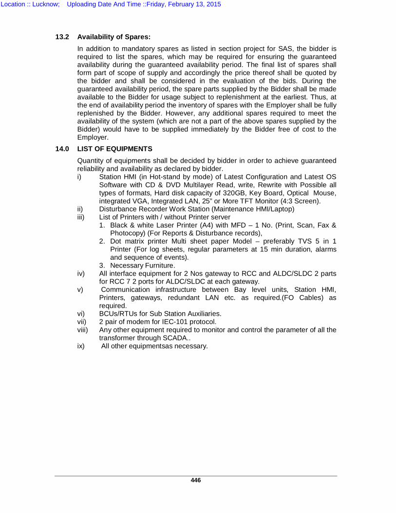
446
13.2 Availability of Spares:
In addition to mandatory spares as listed in section project for SAS, the bidder is required to list the spares, which may be required for ensuring the guaranteed availability during the guaranteed availability period. The final list of spares shall form part of scope of supply and accordingly the price thereof shall be quoted by the bidder and shall be considered in the evaluation of the bids. During the guaranteed availability period, the spare parts supplied by the Bidder shall be made available to the Bidder for usage subject to replenishment at the earliest. Thus, at the end of availability period the inventory of spares with the Employer shall be fully replenished by the Bidder. However, any additional spares required to meet the availability of the system (which are not a part of the above spares supplied by the Bidder) would have to be supplied immediately by the Bidder free of cost to the Employer.
14.0 LIST OF EQUIPMENTS Quantity of equipments shall be decided by bidder in order to achieve guaranteed reliability and availability as declared by bidder. i) Station HMI (in Hot-stand by mode) of Latest Configuration and Latest OS
Software with CD & DVD Multilayer Read, write, Rewrite with Possible all types of formats, Hard disk capacity of 320GB, Key Board, Optical Mouse, integrated VGA, Integrated LAN, 25” or More TFT Monitor (4:3 Screen).
ii) Disturbance Recorder Work Station (Maintenance HMI/Laptop) iii) List of Printers with / without Printer server
1. Black & white Laser Printer (A4) with MFD – 1 No. (Print, Scan, Fax & Photocopy) (For Reports & Disturbance records),
2. Dot matrix printer Multi sheet paper Model – preferably TVS 5 in 1 Printer (For log sheets, regular parameters at 15 min duration, alarms and sequence of events).
3. Necessary Furniture. iv) All interface equipment for 2 Nos gateway to RCC and ALDC/SLDC 2 parts
for RCC 7 2 ports for ALDC/SLDC at each gateway. v) Communication infrastructure between Bay level units, Station HMI,
Printers, gateways, redundant LAN etc. as required.(FO Cables) as required.
vi) BCUs/RTUs for Sub Station Auxiliaries. vii) 2 pair of modem for IEC-101 protocol. viii) Any other equipment required to monitor and control the parameter of all the
transformer through SCADA.. ix) All other equipmentsas necessary.
Location :: Lucknow; Uploading Date And Time ::Friday, February 13, 2015
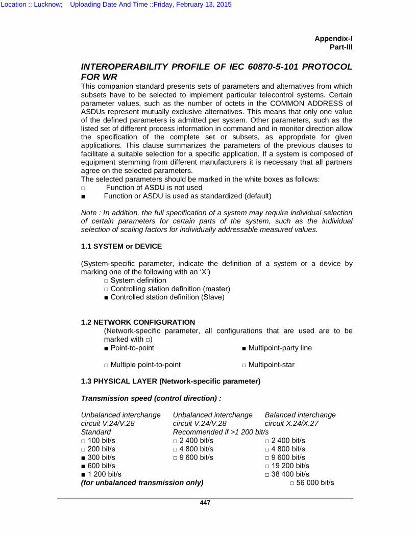
447
Appendix-I
Part-III INTEROPERABILITY PROFILE OF IEC 60870-5-101 PROTOCOL FOR WR This companion standard presents sets of parameters and alternatives from which subsets have to be selected to implement particular telecontrol systems. Certain parameter values, such as the number of octets in the COMMON ADDRESS of ASDUs represent mutually exclusive alternatives. This means that only one value of the defined parameters is admitted per system. Other parameters, such as the listed set of different process information in command and in monitor direction allow the specification of the complete set or subsets, as appropriate for given applications. This clause summarizes the parameters of the previous clauses to facilitate a suitable selection for a specific application. If a system is composed of equipment stemming from different manufacturers it is necessary that all partners agree on the selected parameters. The selected parameters should be marked in the white boxes as follows: Function of ASDU is not used Function or ASDU is used as standardized (default) Note : In addition, the full specification of a system may require individual selection of certain parameters for certain parts of the system, such as the individual selection of scaling factors for individually addressable measured values. 1.1 SYSTEM or DEVICE (System-specific parameter, indicate the definition of a system or a device by marking one of the following with an ‘X’)
System definition Controlling station definition (master) Controlled station definition (Slave)
1.2 NETWORK CONFIGURATION
(Network-specific parameter, all configurations that are used are to be marked with ) Point-to-point Multipoint-party line Multiple point-to-point Multipoint-star
1.3 PHYSICAL LAYER (Network-specific parameter) Transmission speed (control direction) : Unbalanced interchange Unbalanced interchange Balanced interchange circuit V.24/V.28 circuit V.24/V.28 circuit X.24/X.27 Standard Recommended if >1 200 bit/s 100 bit/s 2 400 bit/s 2 400 bit/s 200 bit/s 4 800 bit/s 4 800 bit/s 300 bit/s 9 600 bit/s 9 600 bit/s 600 bit/s 19 200 bit/s 1 200 bit/s 38 400 bit/s (for unbalanced transmission only) 56 000 bit/s
Location :: Lucknow; Uploading Date And Time ::Friday, February 13, 2015
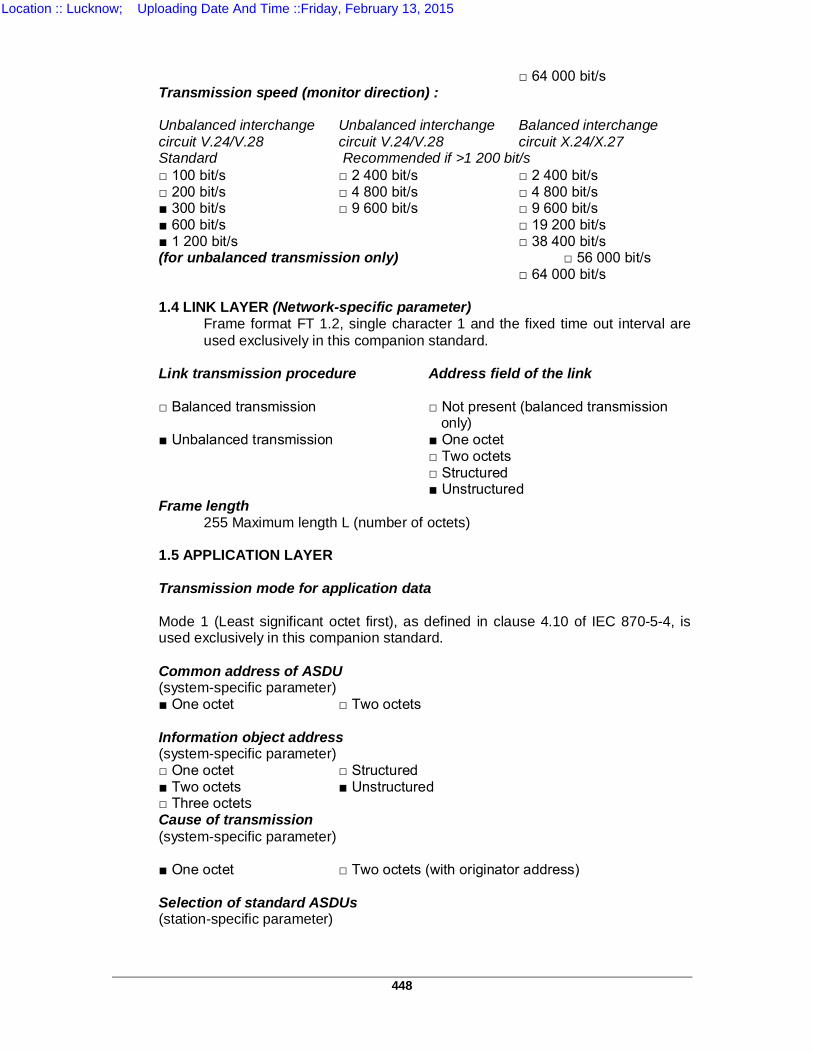
448
64 000 bit/s
Transmission speed (monitor direction) : Unbalanced interchange Unbalanced interchange Balanced interchange circuit V.24/V.28 circuit V.24/V.28 circuit X.24/X.27 Standard Recommended if >1 200 bit/s 100 bit/s 2 400 bit/s 2 400 bit/s 200 bit/s 4 800 bit/s 4 800 bit/s 300 bit/s 9 600 bit/s 9 600 bit/s 600 bit/s 19 200 bit/s 1 200 bit/s 38 400 bit/s (for unbalanced transmission only) 56 000 bit/s
64 000 bit/s 1.4 LINK LAYER (Network-specific parameter)
Frame format FT 1.2, single character 1 and the fixed time out interval are used exclusively in this companion standard.
Link transmission procedure Address field of the link
Balanced transmission Not present (balanced transmission only) Unbalanced transmission One octet
Two octets Structured Unstructured
Frame length 255 Maximum length L (number of octets)
1.5 APPLICATION LAYER Transmission mode for application data Mode 1 (Least significant octet first), as defined in clause 4.10 of IEC 870-5-4, is used exclusively in this companion standard. Common address of ASDU (system-specific parameter) One octet Two octets
Information object address (system-specific parameter) One octet Structured Two octets Unstructured Three octets Cause of transmission (system-specific parameter)
One octet Two octets (with originator address)
Selection of standard ASDUs (station-specific parameter)
Location :: Lucknow; Uploading Date And Time ::Friday, February 13, 2015
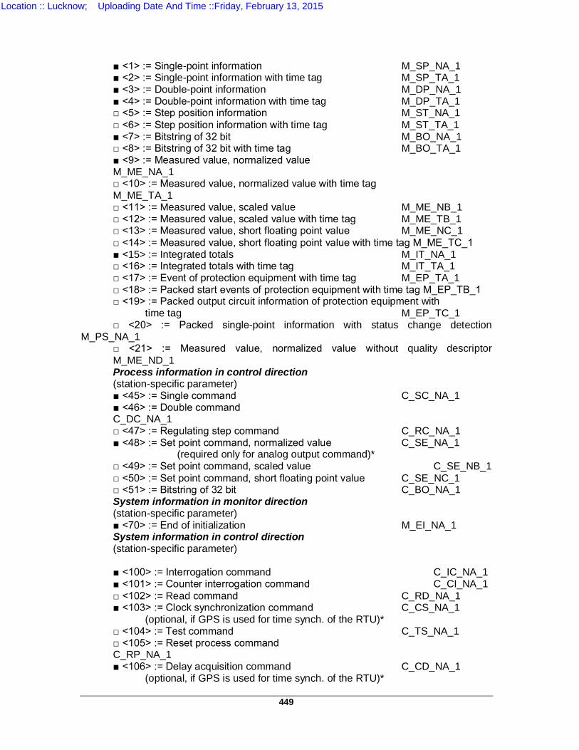
449
<1> := Single-point information M_SP_NA_1 <2> := Single-point information with time tag M_SP_TA_1 <3> := Double-point information M_DP_NA_1 <4> := Double-point information with time tag M_DP_TA_1 <5> := Step position information M_ST_NA_1 <6> := Step position information with time tag M_ST_TA_1 <7> := Bitstring of 32 bit M_BO_NA_1 <8> := Bitstring of 32 bit with time tag M_BO_TA_1 <9> := Measured value, normalized value
M_ME_NA_1 <10> := Measured value, normalized value with time tag
M_ME_TA_1 <11> := Measured value, scaled value M_ME_NB_1 <12> := Measured value, scaled value with time tag M_ME_TB_1 <13> := Measured value, short floating point value M_ME_NC_1 <14> := Measured value, short floating point value with time tag M_ME_TC_1 <15> := Integrated totals M_IT_NA_1 <16> := Integrated totals with time tag M_IT_TA_1 <17> := Event of protection equipment with time tag M_EP_TA_1 <18> := Packed start events of protection equipment with time tag M_EP_TB_1 <19> := Packed output circuit information of protection equipment with
time tag M_EP_TC_1 <20> := Packed single-point information with status change detection
M_PS_NA_1 <21> := Measured value, normalized value without quality descriptor M_ME_ND_1 Process information in control direction (station-specific parameter) <45> := Single command C_SC_NA_1 <46> := Double command
C_DC_NA_1 <47> := Regulating step command C_RC_NA_1 <48> := Set point command, normalized value C_SE_NA_1
(required only for analog output command)* <49> := Set point command, scaled value C_SE_NB_1 <50> := Set point command, short floating point value C_SE_NC_1 <51> := Bitstring of 32 bit C_BO_NA_1 System information in monitor direction (station-specific parameter) <70> := End of initialization M_EI_NA_1 System information in control direction (station-specific parameter) <100> := Interrogation command C_IC_NA_1 <101> := Counter interrogation command C_CI_NA_1 <102> := Read command C_RD_NA_1 <103> := Clock synchronization command C_CS_NA_1
(optional, if GPS is used for time synch. of the RTU)* <104> := Test command C_TS_NA_1 <105> := Reset process command
C_RP_NA_1 <106> := Delay acquisition command C_CD_NA_1
(optional, if GPS is used for time synch. of the RTU)*
Location :: Lucknow; Uploading Date And Time ::Friday, February 13, 2015
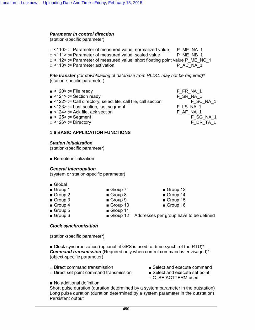
450
Parameter in control direction (station-specific parameter)
<110> := Parameter of measured value, normalized value P_ME_NA_1 <111> := Parameter of measured value, scaled value P_ME_NB_1 <112> := Parameter of measured value, short floating point value P_ME_NC_1 <113> := Parameter activation P_AC_NA_1 File transfer (for downloading of database from RLDC, may not be required)* (station-specific parameter)
<120> := File ready F_FR_NA_1 <121> := Section ready F_SR_NA_1 <122> := Call directory, select file, call file, call section F_SC_NA_1 <123> := Last section, last segment F_LS_NA_1 <124> := Ack file, ack section F_AF_NA_1 <125> := Segment F_SG_NA_1 <126> := Directory F_DR_TA_1
1.6 BASIC APPLICATION FUNCTIONS
Station initialization (station-specific parameter)
Remote initialization
General interrogation (system or station-specific parameter)
Global Group 1 Group 7 Group 13 Group 2 Group 8 Group 14 Group 3 Group 9 Group 15 Group 4 Group 10 Group 16 Group 5 Group 11 Group 6 Group 12 Addresses per group have to be defined
Clock synchronization (station-specific parameter)
Clock synchronization (optional, if GPS is used for time synch. of the RTU)* Command transmission (Required only when control command is envisaged)* (object-specific parameter)
Direct command transmission Select and execute command Direct set point command transmission Select and execute set point
C_SE ACTTERM used No additional definition Short pulse duration (duration determined by a system parameter in the outstation) Long pulse duration (duration determined by a system parameter in the outstation) Persistent output
Location :: Lucknow; Uploading Date And Time ::Friday, February 13, 2015
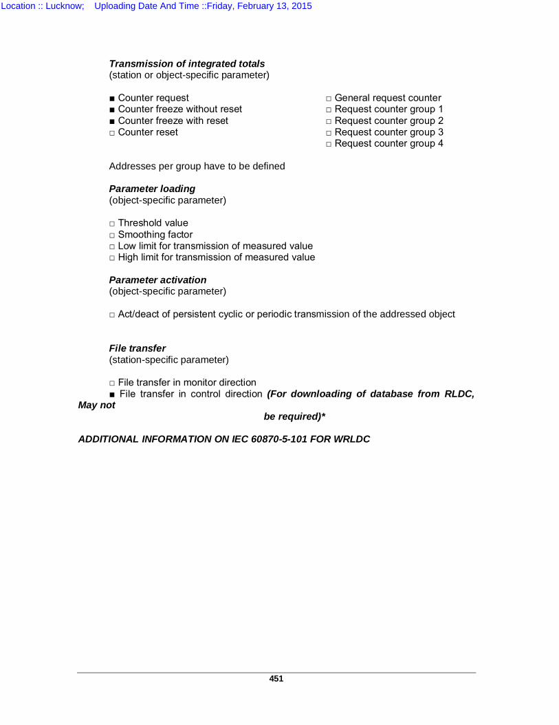
451
Transmission of integrated totals (station or object-specific parameter)
Counter request General request counter Counter freeze without reset Request counter group 1 Counter freeze with reset Request counter group 2 Counter reset Request counter group 3
Request counter group 4
Addresses per group have to be defined Parameter loading (object-specific parameter)
Threshold value Smoothing factor Low limit for transmission of measured value High limit for transmission of measured value
Parameter activation (object-specific parameter)
Act/deact of persistent cyclic or periodic transmission of the addressed object
File transfer (station-specific parameter)
File transfer in monitor direction File transfer in control direction (For downloading of database from RLDC,
May not be required)*
ADDITIONAL INFORMATION ON IEC 60870-5-101 FOR WRLDC
Location :: Lucknow; Uploading Date And Time ::Friday, February 13, 2015
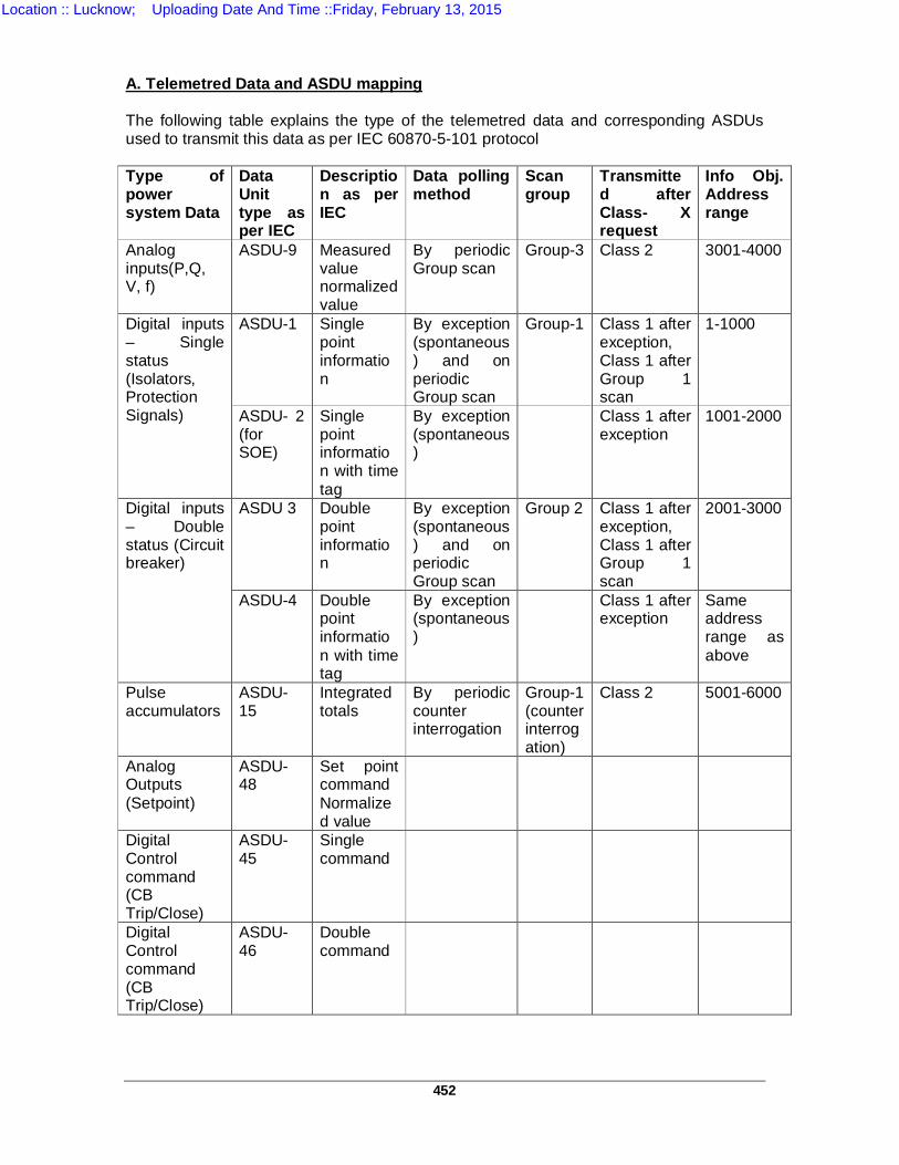
452
A. Telemetred Data and ASDU mapping The following table explains the type of the telemetred data and corresponding ASDUs used to transmit this data as per IEC 60870-5-101 protocol Type of power system Data
Data Unit type as per IEC
Description as per IEC
Data polling method
Scan group
Transmitted after Class- X request
Info Obj. Address range
Analog inputs(P,Q, V, f)
ASDU-9 Measured value normalized value
By periodic Group scan
Group-3 Class 2 3001-4000
Digital inputs – Single status (Isolators, Protection Signals)
ASDU-1 Single point information
By exception (spontaneous) and on periodic Group scan
Group-1 Class 1 after exception, Class 1 after Group 1 scan
1-1000
ASDU- 2 (for SOE)
Single point information with time tag
By exception (spontaneous)
Class 1 after exception
1001-2000
Digital inputs – Double status (Circuit breaker)
ASDU 3 Double point information
By exception (spontaneous) and on periodic Group scan
Group 2 Class 1 after exception, Class 1 after Group 1 scan
2001-3000
ASDU-4 Double point information with time tag
By exception (spontaneous)
Class 1 after exception
Same address range as above
Pulse accumulators
ASDU-15
Integrated totals
By periodic counter interrogation
Group-1 (counter interrogation)
Class 2 5001-6000
Analog Outputs (Setpoint)
ASDU-48
Set point command Normalized value
Digital Control command (CB Trip/Close)
ASDU-45
Single command
Digital Control command (CB Trip/Close)
ASDU-46
Double command
Location :: Lucknow; Uploading Date And Time ::Friday, February 13, 2015
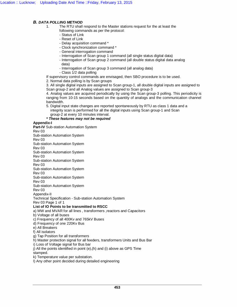
453
B. DATA POLLING METHOD
1. The RTU shall respond to the Master stations request for the at least the following commands as per the protocol:
- Status of Link - Reset of Link - Delay acquisition command * - Clock synchronization command * - General interrogation command - Interrogation of Scan group 1 command (all single status digital data) - Interrogation of Scan group 2 command (all double status digital data analog data) - Interrogation of Scan group 3 command (all analog data) - Class 1/2 data polling
If supervisory control commands are envisaged, then SBO procedure is to be used. 2. Normal data polling is by Scan groups 3. All single digital inputs are assigned to Scan group-1, all double digital inputs are assigned to Scan group-2 and all Analog values are assigned to Scan group-3 4. Analog values are acquired periodically by using the Scan group-3 polling. This periodicity is ranging from 10-15 seconds based on the quantity of analogs and the communication channel bandwidth. 5. Digital input state changes are reported spontaneously by RTU as class 1 data and a integrity scan is performed for all the digital inputs using Scan group-1 and Scan group-2 at every 10 minutes interval. * These features may not be required
Appendix-I Part-IV Sub-station Automation System Rev 03 Sub-station Automation System Rev 03 Sub-station Automation System Rev 03 Sub-station Automation System Rev 03 Sub-station Automation System Rev 03 Sub-station Automation System Rev 03 Sub-station Automation System Rev 03 Sub-station Automation System Rev 03 Appendix-II Technical Specification - Sub-station Automation System Rev 03 Page 1 of 1 List of IO Points to be transmitted to RSCC a) MW and MVAR for all lines , transformers ,reactors and Capacitors b) Voltage of all buses c) Frequency of all 400Kv and 765kV Buses d) Frequency of one 220Kv Bus e) All Breakers f) All isolators g) Tap Position for all transformers h) Master protection signal for all feeders, transformers Units and Bus Bar i) Loss of Voltage signal for Bus bar j) All the points identified in point (e),(h) and (i) above as GPS Time stamped. k) Temperature value per substation. l) Any other point decided during detailed engineering
Location :: Lucknow; Uploading Date And Time ::Friday, February 13, 2015
454
TS-9 TECHNICAL SPECIFICATIONS FOR MICROPROCESSOR BASED THREE PHASE FOUR WIRE 0.2s ACCURACY CLASS STATIC ELECTRONIC ABT
TYPE TRIVECTOR ENERGY METERS 1.0 SCOPE
This specification covers the design, engineering, manufacturing, assembly, and testing before supply and delivery at site supply, installation, testing at site and successful commissioning CT and VT operated microprocessor based 3-phase 4-wire metering system with 0.2s accuracy class energy meters , associated essential equipments, along with accessories, and associated Base Computer Software (as detailed in this specification) One static type composite meter along with one check meter shall be installed for each circuit, as a self-contained device for measurement of power transmittals, as described herein, in each successive 15 minute block, and certain other functions, detailed in the following paragraphs.
All meters shall be capable for implementing the Availability Based Tariff (ABT) on user configurable data. The metering system shall be capable for transferring all the required
metering data of each sub station to remote computers on line and on real time basis, (supply of computers is not under the scope of this specification) to a central location, as per requirements of Meter Polling Software enclosed herein. The metering system shall include a MODEM also for transferring all the
relevant metering data of each sub station to remote computers. (Supply of computers is not under the scope of this specification and shall be arranged by the purchaser) via GPRS/Optical fibre, using standard protocols.
1.1 The material shall, however, conform in all respects to the best industry
standards of engineering, design and workmanship and shall be capable of performing for continuous commercial operation in a manner acceptable to the purchaser, who will interpret the meanings of drawings and specification and shall have the power to reject any work or material which in his judgment is not in accordance therewith. The offered equipment shall be complete in all respects including all components, accessories and devices for effective and trouble free operation according to the specifications. Such components, devices, software, time correction utility etc., shall be deemed to be within the scope of contractor’s supply irrespective of whether they are specifically brought out in the scope of supplies, or not.
If desired, the supplier may be required to coordinate with the prospective SCADA vendor to ensure that the supplied meters are successfully integrated with the purchaser’s communication system.
2.0 APPLICABLE STANDARDS 2.1 STANDARDS FOR METERS
The meters shall conform (for testing, performance and accuracy) in all respects the relevant Indian/International standards with latest amendments thereof unless otherwise specified.
Location :: Lucknow; Uploading Date And Time ::Friday, February 13, 2015
455
IEC: 687-1992 - Alternating Current Static watt-hour meters for measurement of active energy, class 0.2.
CBIP Technical Report No. 88 (read with latest amendments issued) – specifications for AC Static Electricity Energy Meters.
IEC:1268 (1995) Alternating Current Static VAr hour meters for reactive
energy.
IS:14697 (1999) AC static transformer operated Watt-hour and VAR-hour meters for class 0.2s and 0.5s.
IS:15959:2011 – Indian standard for Data exchange for Electricity Meter Reading, Tariff and Load control- Companion specification.
Degree of Protection – IS :12063
Climatic Proofing of Electrical Equipment – IS: 3202.
Color for ready mixed paints IS:5 (For Metering Cubicles) 3.0 SERVICE CONDITIONS
The meters to be supplied against this specification shall be required to operate satisfactorily, accurately and continuously under the following tropical conditions of hot, humid , dusty, rust and fungus prone environment .
i. Location At 400/220/132kV Sub Stations in Uttar
Pradesh ii. Max. ambient air temperature ( C ) 50 iii. Min. ambient air temperature ( C ) 2 iv. Average daily ambient air temp. ( C ) 32 v. Max. Relative Humidity (% ) 74 vi. Max. Altitude above mean sea level (m) 1000 vii. Average Annual Rainfall (mm) 1200 viii. Max. wind pressure ( Kg / Sq.m) 195 ix. Isoceraunic level ( days per year) 50 x. Seismic level (Horizontal Accn.) 0.3 g
4.0 PRINCIPAL PARAMETERS The energy meters shall be indoor/outdoor type connected with the secondary side of out door current and voltage transformers.
Sl.No. Item Specification i. Type of Installation Indoor ii. CT secondary 1 A iii. VT secondary 110 V/ 3 Volts iv. System frequency 50HZ + 5% v. Earthing System Solidly Grounded
Location :: Lucknow; Uploading Date And Time ::Friday, February 13, 2015
456
5.0 TECHNICAL REQUIREMENTS 5.1 The meters shall be suitable for being connected directly through its terminal block to voltage transformers (VTs) having a rated secondary line- to- line voltage of 110 V, and to current transformers (CTs) having a rated secondary current of 1A. Any further transformers/transducers required for their functioning shall be in-built in the meters. Necessary isolation and/or suppression shall also be built-in, for protecting the meters from surges and voltage spikes that occur in the VT and CT circuits in extra high voltage switchyards. 5.2 The active energy (Wh) measurement shall be carried out on 3 phase, 4 wire
principle with an accuracy as per class 0.2 of IEC –687 1992-06 (Second edition). The energy shall be computed directly in CT and VT secondary quantities, and indicated in watt-hours. The meters shall compute the active energy and load import (W & Wh), active energy and load export (W & Wh) from the substation bus bars during each successive 15 minute block, and store it in its memory. It shall also display on demand the 15 - minute energy (Wh) (Import and Export Shall be displayed in separate registers, or with a +/- sign) for the previous 15-minute block. Additionally, the meter shall also display cumulative active energy import (Wh) and active energy export (Wh) using same option.
Meters shall be suitable for working under balanced / unbalanced loads at full power factor range i.e. Zero lag-Unity-Zero lead. The display shall preferably indicate direct values without having to apply any multiplying factor. The meters shall also be able to work correctly on railway traction feeders, which has a provision of only two phases. No. of meters, to be allotted for railway traction feeders, shall be intimated at a time of allotment.
5.3 The meter shall continuously compute the average of the RMS values
(fundamental only) of the three line-to-neutral VT secondary voltage as a percentage of 63.51 V, and display the same on demand.
5.4 The meter shall also compute the reactive power (VAR) on 3-phase, 4-wire
principle, with an accuracy as specified in clause 5.6, and integrate the reactive energy (VARh) algebraically into two separate registers, one for the period for which the average RMS voltage is 103% or higher, and the other for the period for which the average RMS voltage is below 97.0%. The current reactive power (VAR), with a minus sign if negative, and cumulative reactive energy (VARh) readings of the two registers shall be displayed on demand. The readings of the two registers at each midnight shall also be stored in the meter’s memory. The reactive power and reactive energy transmittals shall be computed in VAR/VARh directly calculated in CT and VT secondary quantities. Lagging & Leading reactive power flow on both export and import events shall either be recorded through a +/- sign or on separate registers.
Location :: Lucknow; Uploading Date And Time ::Friday, February 13, 2015
457
5.5 The meters shall fully comply with all stipulations in IEC Publication 687
1992-06 (Second Edition) for 0.2s class Static watt-hour meters, except those specifically modified by this specification. The reference ambient temperature shall be 27+/-02 ° C.
5.6 Errors shall comply with CBIP recommendations for all power factor angles
from 0 to 360 degrees. For reactive power (VAR) and reactive energy (VARh) measurement limits of errors for both active as well as reactive energy in all the four quadrants shall be in accordance to IEC 687, as detailed herein separately.
5.7 The meter display shall be of dot matrix format Alfa numeric LCD (with back-
lit) or LED type. Suitable, protected and sealable enclosure shall be provided for conveniently accessing all the metering data using soft keypad/push buttons.
5.8 The three line-to-neutral voltages shall be continuously, monitored. In case
any of these falls below a value likely to cause malfunctioning of the meter, a visual indication/display shall appear, which shall go off if all three voltages become normal. The time blocks in which such a voltage failure occurs/persist shall also be recorded in the meters memory.
5.9 The meters shall normally operate with the power drawn through the VT
supply. The total burden imposed by a meter for measurement or operation shall not exceed 10 VA on any of the phases. An automatic backup for continued operation of the meter’s calendar& clock, and for retaining all data stored in its memory, shall be provided through a long life battery, which shall be capable of supplying the required power for at least two years. The meters shall be supplied duly fitted with the batteries, which shall not require to be changed for at least ten years, as long as total VT supply interruption does not exceed two years. All the metering data shall be stored in non-volatile memory, which shall not be affected in the event of battery failure.
The meters shall be of self powered type and back up shall be provided
through internal recharge - able battery which allows data downloading/data communication to a remote terminal through optical port/remote communication port in the event of supply failure.
5.10 Each meter shall have a built in calendar and clock, having an accuracy of +/-02 minutes per year or better. The calendar and clock shall be correctly set at the manufacturer’s works. The date (day-month-year) and time (hour-min-sec) shall be displayed on the meter front on demand. Only limited clock adjustment by authorized users, after password authentication shall be possible at site, using the MRI or remotely using time synchronization signal through remote network. All clock corrections shall be registered in the meters memory and suitably shown on print out of collected data.
5.11 Each meter shall have a unique identification code, which shall be marked permanently on its front, as well as in its memory. All meters supplied to UPPTCL as per this specification shall have their identification code starting with “UP”, which shall not be used for any other supplies. UP shall be followed by a dash and a four digit running serial number, further followed by a dash and “A”. (‘A’ being adopted to indicate 1Amp CT secondary).
Location :: Lucknow; Uploading Date And Time ::Friday, February 13, 2015
458
5.12 Each of the metering system shall measure and display the following
quantities/parameters as required: a) Processor’s identification code and model: UP1234A. b) LED/LCD segment check c) Real Time d) Date dd-mm-yy e) Cumulative active energy import (kWh) f) Last 15 minutes block average of the active power / load import. g) Cumulative active energy export (kWh). h) Last 15 minutes block average of the active power / load export. i) Cumulative Reactive energy for the voltage high condition. (ie. Net
kVarh when RMS voltage >103%Vn. j) Cumulative Reactive energy for voltage low condition. (ie. Net kVarh
when RMS voltage <97%Vn. k) Instantaneous three phase average power factor with
sign/display/legend for lag/lead. l) Instantaneous Phase Voltage.
i) R Phase ii) Y Phase iii) B Phase m) Instantaneous Line Currents (Amps). i) R Phase Line Current ii) Y Phase Line Current iii) B Phase
Line Current. n) Instantaneous Frequency. o) Phase Sequence of voltages (alternatively, this may be provided at
MRI/BCS end. p) Instantaneous Active Load in Watt (kW). q) Instantaneous Reactive Load in kVar.
5.13 Other display on selection through key pad-
a) Cumulative active energy import reading (kWh) of predefined date & time for monthly billing purpose.
b) Cumulative active energy export reading (kWh) of predefined date & time for monthly billing purpose.
5.14 Each meter shall have a non-volatile memory in which the following shall be
automatically stored in each successive 15 minutes’ block: 1. Active Energy Import 2. Active Energy Export 3. Average frequency 4. Average load (kW) 5. Average system voltage 6. Reactive Energy lag (when Active Energy Import). 7. Reactive Energy lead (when Active Energy Import). 8. Reactive Energy lag (when Active Energy Export). 9. Reactive Energy lead (when Active Energy Export). 10. Power off time.
15-minute average of the above parameters shall be available for last at least 35 days. The load survey data should be available in the form of bar charts as well as in spreadsheets. The BCS shall have the facility to give complete time synchronized load survey data both in numeric and graphic form.
Location :: Lucknow; Uploading Date And Time ::Friday, February 13, 2015
459
The offered metering system shall store the midnight values of the
following electrical parameters: 1. Active energy import in 6 digits. 2. Active energy export in 6 digits.
5.15 BILLING PARAMETERS
The metering system shall store following parameters corresponding to defined bill dates- 1. Active energy import, 2. Active energy export, 3. Reactive high energy register 4. Reactive low energy register 5. Maximum Demand (Import and Export).
The meters shall store all the above listed data in their memories for a period of minimum thirty five (35) days.
5.16 Each meter shall have an optical port on its front for tapping all data stored in
its memory. Portable or hand held Common Meter Reading Instruments (CMRI) shall be used for this purpose to serve as the interface between the meters specified above and the local personal computers (PC). The overall intention is to transmit the desired data on line in real time and also tap the data stored in the meter’s memories once a week/month, and dump the same via CMRI to a PC running the BCS software, via an independent communication bus architecture. It shall also be possible to obtain a print out (hard copy) of all data collected from the meters, using the local PC.
The whole system shall be such as to provide a print out (both from the local PC, and from remote central computer) in a user defined format to be informed later on. The BCS software shall be programmed to get customized outputs.
Each meter shall also have a visual test output device having either a
single switch able output device or two separate output devices for checking the accuracy of active energy (Wh) as well as reactive energy (Varh). Suitable pulsing rate shall be adopted for wh and varh measurements.
5.17 The meters shall safely withstand the usual fluctuations arising during faults
etc. In particular, VT secondary voltage 115% of rated voltage applied continuously and 190% of rated voltage applied for 3.0 seconds, and CT secondary current 150% of rated current applied continuously and 30 times of rated applied for 0.5 seconds shall not cause any damage to or mal-operation of the meters. The immunity to external magnetic field shall be strictly as per latest CBIP recommendations.
5.18 In addition to optical port & RS-232 port for data communication, the ABT
meter should also have RS-485(in & out) port. Also all the communication ports should work & communicate simultaneously.
5.19 The meters shall also withstand without any damage or mal operation,
reasonable mechanical shocks, earthquake forces, ambient temperature variations, relative humidity etc. They shall have not less than an IP-51 category of construction, and shall be capable of satisfactory operation in an indoor/outdoor, non-air-conditioned installation.
Location :: Lucknow; Uploading Date And Time ::Friday, February 13, 2015
460
5.20 The meters shall continue to function, as specified above, in case of failure of
one or two phases of VT supply. In case of a complete VT supply failure, the computation of average frequency shall be done only for the period during which the VT supply was available in the 15 – minute block. Any time block contraction or elongation for clock correction shall also be duly accounted for.
5.21 The harmonics shall be filtered out while measuring Wh, VAR and VARh, and
only fundamental qualities shall be measured/computed. 5.23 Meters shall be able to store reactive energy consumption during the
specified peak hour period in addition to total active energy consumption. Peak - hour period will be as intimated by the Engineer Of Contract. It shall be possible to retrieve this data through communication ports. Meters shall also be able for implementing the TOD consumption on multiple tariff rates on per day basis.
The TOD Zones shall be as follows:
a) 17:00 to 22:00 hrs. b) 22:00 to 06:00 hrs. c) 06:00 to 10:00 hrs. d) 10:00 to 17:00 hrs.
5.24 If desired by the purchaser, all features of the meter including remote
communication via an adopted communication network shall be demonstrated by the bidder at a randomly selected site so as to ensure complete integration of the offered system with the communication system of the purchaser.
6.0 TAMPER AND ANOMALY DETECTION FEATURES
The meters shall have an appropriate recording system whereby any attempt of tampering the meter is promptly registered with date and time tagging. The system should be able to provide the following information pertaining to tampering events taken place since last demand reset.
The meter should have features to detect the occurrence and restoration of, at least, the following anomaly:
a) Potential Imbalance: The meter shall be capable of detecting and recording
occurrence and restoration of unbalance of voltage. In case of occurrence of such an event a pulse output shall be given through a volt free contact. The rating of the contact shall be 110/220 V DC, 100mA.) Following tamper features shall be available on the display units: - Voltage unbalance - R phase potential missing - Y phase potential missing - B phase potential missing - Feeder supply fail
b) Current Imbalance: The meter shall be capable of detecting and recording occurrence and restoration of unbalance of current. In case of such a event a pulse output shall be given through a volt free contact. The rating of the contact shall be 110V DC, 100mA.
Following tamper features shall be available on the display units: - Current imbalance - R phase current missing
Location :: Lucknow; Uploading Date And Time ::Friday, February 13, 2015
461
- Y phase current missing - B phase current missing - R phase CT reversal - Y phase CT reversal - B phase CT reversal
Logic for calculation of voltage and current imbalance shall be furnished by the tenderer. Last 20 such events shall be stored in the meter. Tamper data shall be available in the specified format below: i) Date of first occurrence of tampering. ii) Time of first occurrence of tampering. iii) Time of first restoration of tampering. iv) Date of last restoration to normal condition. v) Number of occurrence of tampering events.
7.0 SELF DIAGNOSTIC FEATURES The meter shall have the facility of continuous and automatic monitoring of the healthiness of its various electronic devices and circuits. In case of malfunctioning of any of the device and circuit, the meter shall indicate the same with convenient means.
8.0 CUBICLES FOR METERING SYSTEM 8.1 Suitable metering cubicles shall be supplied to mount the meters and
associated terminal blocks, MODEMS, power supply etc. as a stand alone unit to be installed at each substation, which shall be capable of supporting all Main & Check meters. At least eight meters (Four main and four check) along with necessary hardware shall be installed in one metering cubicle. Provision shall be made to enable a MODEM to communicate across all the Main/ Check meters, thereby providing remote access using networks as per 8.3. A total of two nos. modems, one no. for all Main meters and one no. for all Check meters are to be provided in each metering cubicle. The metering cubicle shall have a door switch and space heater controlled by thermostat and switch, powered by 220V auxiliary AC supply.
8.2 The cubicles, confirming to at least IP 55 degree of protection shall be
properly treated and painted with light gray shade no. 631 as per IS 5. The wiring shall be carried out with multi-core super flexible, fire retardant, low smoke, PVC insulted color coded wires of 2.5 Sq. mm. cross section and 1.1 KV grade.
The load bearing members and frames shall be made of 2 mm CRCA and doors and covers shall be fabricated from 1.6 mm CRCA.
8.3 All meters within one cubicle shall be connected to a common data highway
through a standard RS232 link. A suitable AC powered MODEM to communicate via GPRS/Optical fibre at a minimum speed of 512 kbps should be provided for data exchange with purchaser’s remote computer, via an arrangement using separate MODEM for main meters and check meters.
8.4 The MODEM and the power supplies as described shall be suitably partitioned
from the main & check meters.
Location :: Lucknow; Uploading Date And Time ::Friday, February 13, 2015
462
8.5 A total of eight nos. Test Terminal blocks (TTB), one for each meter, are to
be provided in each metering cubicle. The TTB are to be provided with sealable top covers screws and these are to be mounted inside the metering cubicle in such a way that they are accessible only when the door of the metering cubicle is in open condition. The cables coming from the outdoor CTs/PTs for each of the eight nos. meters are to be connected to the Terminal blocks, suitable nos. of which are to be provided inside the metering cubicle. Necessary wiring is to be provided between the Terminal blocks and each of the TTBs and between the TTBs & location where each meter is to be housed inside the metering cubicle.
8.6 The front side of the meter shall be clearly accessible for accessing the data directly or through the MRI.
8.7 Suitable sealing arrangements are to be provided in each metering cubicle. 8.8 The bidder has to provide the detailed drawings of the metering cubicle, alongwith its all accessories. 8.9 The minimum dimensions of the metering cubicle shall be 1500mm x 600mm x 600mm (HxWxD) 8.10 The metering cubicle of the ABT metering system shall be its integral part and the bidders are intimated that the price evaluation shall be carried out after including the prices of the ABT meters and the metering cubicle. The successful bidder shall have to supply the ABT meters alongwith the metering cubicle. 9.0 SEALING ARRANGEMENT
Each meter, shall be able to be sealed individually, including the optical communication port.
Suitable arrangement shall be provided for frequent access to meter readings only, without requiring to fiddle the meter seals and that of the metering cubicle.
10.0 The bidder shall be responsible for commissioning of the metering cubicle
along with the ABT meters, mounted inside the metering cubicle at each substation. Normally one cubicle is allotted for one substation. Separate rates are to be quoted for commissioning of the metering cubicle and each ABT meter, mounted inside the cubicle, as the no. of ABT meters to be installed inside the cubicle may vary from substation to substation.
Location :: Lucknow; Uploading Date And Time ::Friday, February 13, 2015
463
REQUIREMENT AND FEATURES OF THE BASE COMPUTER
SOFTWARE
The BCS shall have at least the following facilities/features: i) It shall be possible to read data received from the meter reading
instrument/data collection device. ii) It shall be possible to dial the ABT meters installed at remote sites and read. iii) It shall be possible to schedule the metering system for a sequence of
automatic dialling and reading the metering module. iv) It shall be possible to export the data in both ASCII and XML formats for
detailed analysis and billing. v) It shall be include appropriate multilevel security/password protection for
control inputs and data output so that unauthorised person does not have access to the critical system data.
vi) The BCS shall be executable on MS WINDOWS 98/2000/XP operating system.
vii) The application software shall be fully compatible for implementing ABT, TOD, Tamper and anomalies in a user friendly and user definable format.
viii) It should be possible to have selective print out of all the available data of the meter. The user need not revert back to the supplier of the software for modifying the software in case of change in print out data eg. TOD, ABT, Tamper and other data are required.
ix) It is very important that the BCS has the feature to export the available data to ASCII and XML or spread sheet format for integrating with the UPPCL’s billing system taking into account the ABT and TOD features.
x) The BCS shall have a multilevel password for data protection and security. The first level should allow the user to enter the system. The different software features shall be protected by different passwords. The configuration of password should be user definable.
xi) Any deviation of readings of main and check meter, beyond a prescribed limit as defined by the user, shall be clearly indicated on priority by the application software.
xii) The BCS software shall also allow computing the net energy, ie. the difference of import and export energy during the desired billing cycle.
BCS software shall be installed and a copy in the form of Compact Disk shall be provided to the respective consignees and as well as to SLDC, UPPTCL.
Compatible MRI software for reading the supplier’s meters shall also be supplied in the form of Compact Disk to the respective consignees.
Location :: Lucknow; Uploading Date And Time ::Friday, February 13, 2015
464
TECHNICAL SPECIFICATION OF METER POLLING SOFTWARE (Not under the scope of Supply)
Data Connectivity Requirement
The Energy Meters procured by UPPTCL and commissioned at most of the
interface points are of 0.2s accuracy class, ABT Compliant electronic energy mounted in rack/panel arrangement. Each metering rack/panel provides at least three communication ports: (a) One Galvanically isolated RS232C serial port (b) Two Optically isolated RS232C serial ports/optical ports for local/remote data transfer. UPPCL has envisaged implementing the scheme for Real time data transfer as well as on-demand data transfer from these meters. Real time data transfer would be used primarily for monitoring (of energy generation/drawl and other relevant parameters in view of ABT application) at the central station. Further, on-demand data transfer will be used for reading the meter (load, frequency, voltage profiles etc.) on a periodic basis as required (say monthly/fortnightly/weekly/daily) for energy accounting and settlement application. The bidder shall be responsible for setting up separate channels for real time data transfer and on-demand data transfer from all these meters using suitable multiplexers / converters and communication cables at each location [One RS232 serial port shall be used for on-demand remote communication and other RS485 serial ports shall be used for real time data transfer. These communication ports shall thus be used for setting up independent channels for on-line and on-demand data transfer]. These ports shall be capable of Data transfer to a remote computer over suitable communication media (GPRS/leased line/OFC) using suitable communication hardware (modems/multiplexer/communication cables etc.) as required for proper functioning of remote meter reading scheme. Integration of metering system with these communication mediums shall be the responsibility of the bidder.
Base Computer Software has been supplied by meter manufacturer for on-
demand remote communication of data from these meters using PSTN network at present. UPPTCL shall use the above mentioned communication media (GPRS/leased line/OFC) for on-line real time data collection from energy meters. Suitable software for on-line monitoring and on demand data collection using the above communication medium shall be provided by the bidder. Integration of meters and the above communication medium will require physical interconnection between the communication medium and metering systems (having RS232, RS485 serial port outputs) as well as implementation of the suitable comprehensive single software for on-line and on-demand data transfer on the above mentioned communication channel(s). The instantaneous parameters (data) from each energy meter shall be retrieved at central site at least once in five (5) minutes. However, flexibility shall be provided to UPPTCL to increase or decrease the polling cycle time as per requirements in future.
Instantaneous real-time data from each energy meter shall be made available to UPPTCL in ASCII & XML formats also. The exact format (may change from time to time), in which UPPTCL shall require data, will be provided to successful Bidder.
Location :: Lucknow; Uploading Date And Time ::Friday, February 13, 2015
465
Primarily, the meter data includes, but not limited to, following:
a) Real-time Data Transfer: Instantaneous parameters to be polled once in five (5) minutes (Note: Option of “parameter selection” by the User may be provided from given superset of parameters): (i) Active Import (ii) Active Export (iii) Reactive Lag while active import (iv) Reactive Lead while active import (v) Reactive Lag while active export (vi) Reactive Lead while active export (vii) Apparent Import (viii) Apparent Export (ix) Reactive High (x) Reactive Low (xi) Average Frequency (Hz) (xii) Average RMS Voltage (xiii) Meter Time-stamp (Date - “DD MM YY” and Time - “hh mm ss”)
22.1.1 It should be possible to monitor energy and/or demand data for parameters as specified at Sr. Nos. (i) to (x) above.
b) On-demand Data Transfer: Load survey parameters (stored in meter
memory in block of 15-minutes for at least 35 days) to be polled once in a month / once in a fortnight / once in a week. Facility shall be provided to poll all meters automatically (without any human intervention) depending upon the User defined sequence of meter serial numbers: (i) Watt (Import) (ii) Watt (Export) (iii) Volt Ampere Reactive (Lag) when Watt Hour (Import) (iv) Volt Ampere Reactive (Lead) when Watt Hour (Import) (v) Volt Ampere Reactive (Lag) when Watt Hour (Export) (vi) Volt Ampere Reactive (Lead) when Watt Hour (Export) (vii) Average Frequency (Hz) (viii) Average RMS Voltage (kV) (ix) Voltage Low (x) Time Retard (xi) Time Advance
Location :: Lucknow; Uploading Date And Time ::Friday, February 13, 2015
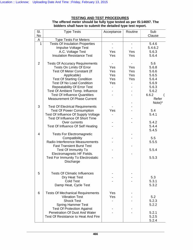
466
TESTING AND TEST PROCEDURES
The offered meter should be fully type tested as per IS:14697. The bidders shall have to submit the detailed type test report.
Sl. No
Type Tests Acceptance Routine Sub Clause
A Type Tests For Meters 1
2 3 4 5 6
Tests Of Insulation Properties Impulse Voltage Test
A.C. Voltage Test Insulation Resistance Test
Tests Of Accuracy Requirements
Tests On Limits Of Error Test Of Meter Constant (If
Applicable) Test Of Starting Condition Test Of No Load Condition Repeatability Of Error Test
Test Of Ambient Temp. Influence Test Of Influence Quantities
Measurement Of Phase Current
Test Of Electrical Requirements Test Of Power Consumption
Test Of Influence Of Supply Voltage Test Of Influence Of Short Time
Over currents Test Of Influence Of Self Heating
Tests For Electromagnetic
Compatibility Radio Interference Measurements
Fast Transient Burst Test Test Of Immunity To
Electromagnetic HF Fields. Test For Immunity To Electrostatic
Discharge
Tests Of Climatic Influences Dry Heat Test
Cold Test Damp Heat, Cycle Test
Tests Of Mechanical Requirements
Vibration Test Shock Test
Spring Hammer Test Test Of Protection Against
Penetration Of Dust And Water Test Of Resistance to Heat And Fire
- -
Yes Yes
-
Yes Yes Yes Yes Yes
- - - -
Yes - - - - - - - - - -
Yes Yes
- - -
- -
Yes Yes
-
Yes Yes Yes Yes
- - - - - - - - - - - - - - - - - - - - -
5.4.6 5.4.6.2 5.6.3 5.6.4
5.6
5.6.8 5.6.6 5.6.5 5.6.4 5.6.9 5.6.3 5.6.2
6.6.2 (Refer Note)*
5.4 5.4.1
5.4.2 5.4.4 5.4.5
5.5
5.5.5
5.5.4
5.5.3
5.3 5.3.1 5.3.2
5.2 5.2.3 5.2.2
5.2.1 5.2.5 5.2.4
Location :: Lucknow; Uploading Date And Time ::Friday, February 13, 2015
467
Notes: 1. For type testing all the above tests are to be carried out except test 2.8 for
which refer note 2. 2. *However, test 2.8 is valid only for meters having additional features as per
clause 6.6 (Of CBIP Recommendations), which, in this case, is not applicable 11.1 If desired by the purchaser, one (1) out of the ordered quantity of meters may
be subjected to the complete range of type tests as per CBIP recommendations and IEC-687 1992-06(Second Edition), after final assembly. In case of any failure to pass all specified tests, the contractor shall arrange to carry out the requisite modifications/replacements in the entire lot of meters at his own cost. After any such modifications and final assembly, two (2) meters selected out of the lot by the owner’s representative shall be subjected to the full range of type tests. The manufacturer shall further commence manufacturing only after these are successfully tested.
11.2 ACCEPTANCE & ROUTINE TESTS 11.2.1 ACCEPTANCE TESTS
All acceptance tests as stipulated in the relevant standards shall be carried out by the supplier in the presence of purchaser's representative. Following additional tests shall be carried out on meters as per procedures of CBIP Technical Report 88 on randomly selected samples. i) Shock Test
ii) Vibration Test
iii) Magnetic Induction of external origin (AC & DC)
iv) Tamper & Fraud Protection as per clause 6.0
(v) High Voltage test on Metering Cubicles.
11.2.2 ROUTINE TESTS
All routine tests as stipulated in the relevant standards shall be carried out. In addition, the following tests including tamper and fraud protection tests shall also be carried out and such routine test certificates shall be submitted for approval of the purchaser.
i) Display of all metering parameters.
ii) Remote communication capabilities.
iii) Data downloading through MRI.
Location :: Lucknow; Uploading Date And Time ::Friday, February 13, 2015
468
TS-10(A)
TECHNICAL SPECIFICATION FOR TUBULAR TYPE LEAD-ACID STATIONARY BATTERIES IN TRANSPARENT SAN CONTAINER. 1.00.0 SCOPE 1.00.01 This specification covers design, manufacture, assembly of
components, testing at manufacturer’s works, packing, supply and delivery to site, Tubular type lead-acid stationary batteries in Transparent SAN container and associated accessories for indoor installation.
1.00.02 Supervision of erection and commissioning of the battery bank shall have to be undertaken. 2.00.0 APPLICABLE STANDARDS (LATEST REVISION) IS-1885 : Electrical vocabulary, secondary cells and batteries IS-1069 : Water for storage batteries IS-266 : Sulphuric acid for storage batteries IS-8320 : General requirements for methods of tests for lead-acid Storage batteries. IS-1146 : Specification for rubber and plastics container for lead acid storage batteries IS-6071 : Synthetic separator for lead acid batteries IEEE-485 : IEEE Recommended practice for sizing of large lead acid Storage batteries for generating stations and substations. IEEE-484 : Recommended practice for design and installation of Storage batteries. IEC896-1 : Stationary Lead-acid Batteries DIN40736: Stationery cells with positive Tubular plates in transparent plastic containers. 3.00.0 DESIGN AND CONSTRUCTIONAL FEATURES OF BATTERY 3.01.01 Type
The battery shall be lead acid Tubular type in Transparent SAN container (OpzS). Sealed Maintenance Free VRLA type/ Nickel Cadmium type batteries are not acceptable. The batteries should preferably be of 2 volts units for 300 AH capacity for compactness and lower foot-print.
3.01.02 Positive Plates :
The plates shall be of first class material and workmanship and shall be free from blowholes, cracks and other imperfections. The tubular positive plates shall consist of a suitable bar with spines cast of suitably alloyed lead to give adequate mechanical strength and minimum electrical resistance.
The tubular spines shall be cast of an alloy of Pb and
Antimony with Antimony content not greater than 3% by weight. The casting shall be done using proper controlled procedure preferably sing high pressure casting machine with an operating pressure not less than 90- 100 Bars. Low antimony alloy (not greater than 3%)
Location :: Lucknow; Uploading Date And Time ::Friday, February 13, 2015
469
will ensure low water loss and a guaranteed topping up frequency of not more than once in 12 months. High pressure cast spines will ensure a long life and trouble-free operation.
Porous, acid resistant and oxidation resistant tubes shall be
inserted one over each spine. After insertion, the tube shall be adequately filled and packed with active material (preferable through a rotary shaking machine) before their lower ends are closed by common plastic bar. The construction and material of tube shall be such as to reduce the loss of active material and shall be able to withstand normal internal stresses developed during service.
3.01.03 Negative Plates : The negative plates shall be of flat pasted type and should be made of lead-calcium alloy. The pasting shall be done on an automated machine for better control of process parameters. It should have adequate mechanical strength and would be so designed that active material is maintained in intimate contact with the grid under normal working conditions throughout the life of the battery.
3.01.04 Separators:
The separators shall be micro-porous type to avoid direct as well as side shorts. It should be acid resistant, chemically inert and should have excellent oxidation resistance and high degree of porosity to ensure minimum internal resistance. Average volume porosity should be more than 45%. It should not exhibit any tendency to swell or shrink at temperature encountered during operation. Micro-porous synthetic separators shall conform to latest IS: 6071
3.01.05 Containers :
Containers shall preferably be made of transparent SAN copolymer giving excellent clarity, outstanding chemical resistance, rigidity and toughness with very high insulating qualities which eliminate the need for separate cell insulators. It shall have adequate mechanical strength to prevent bulging, cracking etc. during the life span of battery when operating under expected temperature range and due to action of static and dynamic loads and the action of electrolyte. These containers should enable the electrolyte level and the cell condition to be monitored at a glance. The containers shall conform to latest edition of IS-1146.
3.01.06 Cell Lids:
It should be moulded from opaque SAN or ABS and sealed to the container. It should be easily removable if the need arises.
3.01.07 Micro-porous Ceramic Vent Plugs :
The vent plugs should be specially designed incorporating a micro-porous ceramic filter which effectively returns all acid spray to the cell, but allow free exit of oxygen and hydrogen which is generated at the end of boost charging. On removal, the plugs shall permit drawing of the electrolyte sample for servicing and of checking of the electrolyte level. The vent plug should preferably be flame-retardant type to prevent any fire hazard in the battery room.
Location :: Lucknow; Uploading Date And Time ::Friday, February 13, 2015
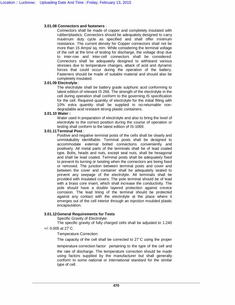
470
3.01.08 Connectors and fasteners :
Connectors shall be made of copper and completely insulated with rubber/plastics. Connectors should be adequately designed to carry maximum duty cycle as specified and shall offer minimum resistance. The current density for Copper connectors shall not be more than 15 Amps/ sq. mm. While considering the terminal voltage of the cell at the time of testing for discharge, the voltage drop due to inter-row and inter-cell connectors shall be considered. Connectors shall be adequately designed to withstand various stresses due to temperature changes, attack of acid and dynamic forces that could occur during the operation of the battery. Fasteners should be made of suitable material and should also be completely insulated.
3.01.09 Electrolyte : The electrolyte shall be battery grade sulphuric acid conforming to latest edition of relevant IS 266. The strength of the electrolyte in the cell during operation shall conform to the governing IS specification for the cell. Required quantity of electrolyte for the initial filling with 10% extra quantity shall be supplied in no-returnable non-degradable acid resistant strong plastic containers.
3.01.10 Water : Water used in preparation of electrolyte and also to bring the level of electrolyte to the correct position during the course of operation or testing shall conform to the latest edition of IS-1069.
3.01.11 Terminal Post : Positive and negative terminal posts of the cells shall be clearly and unmistakably identifiable. Terminal posts shall be designed to accommodate external bolted connections conveniently and positively. All metal parts of the terminals shall be of lead coated type. Bolts, heads and nuts, except seal nuts, shall be hexagonal and shall be lead coated. Terminal posts shall be adequately fixed to prevent its turning or twisting when the connectors are being fixed or removed. The junction between terminal posts and cover and between the cover and container shall be adequately sealed to prevent any seepage of the electrolyte. All terminals shall be provided with insulated covers. The pole terminal should be of lead with a brass core insert, which shall increase the conductivity. The pole should have a double layered protection against crevice corrosion. The lead lining of the terminal should be protected against any contact with the electrolyte at the place where it emerges out of the cell interior through an injection moulded plastic encapsulation.
3.01.12 General Requirements for Tests Specific Gravity of Electrolyte: The specific gravity of fully charged cells shall be adjusted to 1.240 +/- 0.005 at 27˚C. Temperature Correction: The capacity of the cell shall be corrected to 27˚C using the proper
temperature correction factor pertaining to the type of the cell and the rate of discharge. The temperature correction should be made using factors supplied by the manufacturer but shall generally conform to some national or international standard for the similar type of cell.
Location :: Lucknow; Uploading Date And Time ::Friday, February 13, 2015
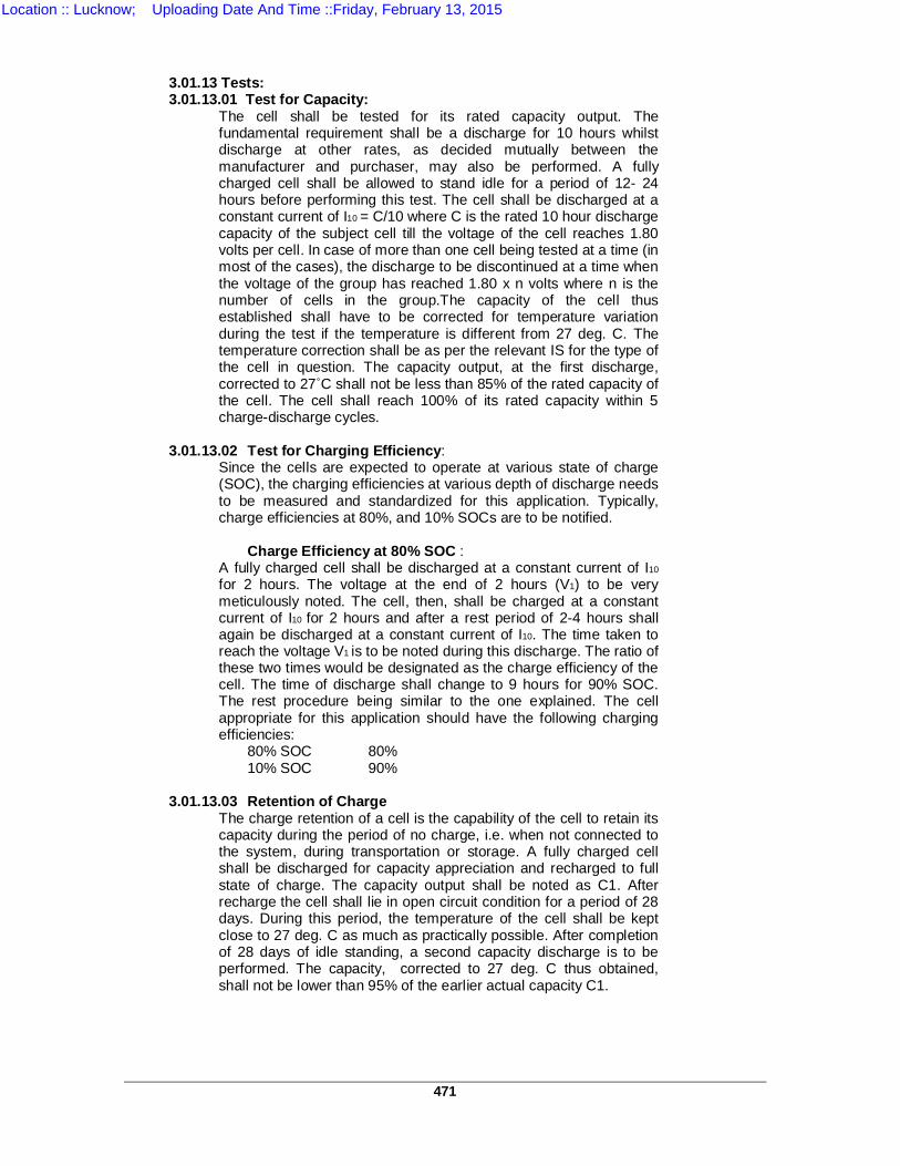
471
3.01.13 Tests: 3.01.13.01 Test for Capacity: The cell shall be tested for its rated capacity output. The
fundamental requirement shall be a discharge for 10 hours whilst discharge at other rates, as decided mutually between the manufacturer and purchaser, may also be performed. A fully charged cell shall be allowed to stand idle for a period of 12- 24 hours before performing this test. The cell shall be discharged at a constant current of I10 = C/10 where C is the rated 10 hour discharge capacity of the subject cell till the voltage of the cell reaches 1.80 volts per cell. In case of more than one cell being tested at a time (in most of the cases), the discharge to be discontinued at a time when the voltage of the group has reached 1.80 x n volts where n is the number of cells in the group.The capacity of the cell thus established shall have to be corrected for temperature variation during the test if the temperature is different from 27 deg. C. The temperature correction shall be as per the relevant IS for the type of the cell in question. The capacity output, at the first discharge, corrected to 27˚C shall not be less than 85% of the rated capacity of the cell. The cell shall reach 100% of its rated capacity within 5 charge-discharge cycles.
3.01.13.02 Test for Charging Efficiency: Since the cells are expected to operate at various state of charge
(SOC), the charging efficiencies at various depth of discharge needs to be measured and standardized for this application. Typically, charge efficiencies at 80%, and 10% SOCs are to be notified.
Charge Efficiency at 80% SOC : A fully charged cell shall be discharged at a constant current of I10
for 2 hours. The voltage at the end of 2 hours (V1) to be very meticulously noted. The cell, then, shall be charged at a constant current of I10 for 2 hours and after a rest period of 2-4 hours shall again be discharged at a constant current of I10. The time taken to reach the voltage V1 is to be noted during this discharge. The ratio of these two times would be designated as the charge efficiency of the cell. The time of discharge shall change to 9 hours for 90% SOC. The rest procedure being similar to the one explained. The cell appropriate for this application should have the following charging efficiencies:
80% SOC 80% 10% SOC 90% 3.01.13.03 Retention of Charge The charge retention of a cell is the capability of the cell to retain its
capacity during the period of no charge, i.e. when not connected to the system, during transportation or storage. A fully charged cell shall be discharged for capacity appreciation and recharged to full state of charge. The capacity output shall be noted as C1. After recharge the cell shall lie in open circuit condition for a period of 28 days. During this period, the temperature of the cell shall be kept close to 27 deg. C as much as practically possible. After completion of 28 days of idle standing, a second capacity discharge is to be performed. The capacity, corrected to 27 deg. C thus obtained, shall not be lower than 95% of the earlier actual capacity C1.
Location :: Lucknow; Uploading Date And Time ::Friday, February 13, 2015
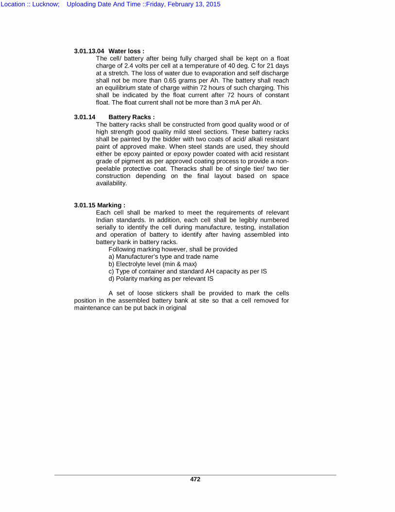
472
3.01.13.04 Water loss : The cell/ battery after being fully charged shall be kept on a float
charge of 2.4 volts per cell at a temperature of 40 deg. C for 21 days at a stretch. The loss of water due to evaporation and self discharge shall not be more than 0.65 grams per Ah. The battery shall reach an equilibrium state of charge within 72 hours of such charging. This shall be indicated by the float current after 72 hours of constant float. The float current shall not be more than 3 mA per Ah.
3.01.14 Battery Racks : The battery racks shall be constructed from good quality wood or of
high strength good quality mild steel sections. These battery racks shall be painted by the bidder with two coats of acid/ alkali resistant paint of approved make. When steel stands are used, they should either be epoxy painted or epoxy powder coated with acid resistant grade of pigment as per approved coating process to provide a non-peelable protective coat. Theracks shall be of single tier/ two tier construction depending on the final layout based on space availability.
3.01.15 Marking : Each cell shall be marked to meet the requirements of relevant
Indian standards. In addition, each cell shall be legibly numbered serially to identify the cell during manufacture, testing, installation and operation of battery to identify after having assembled into battery bank in battery racks.
Following marking however, shall be provided a) Manufacturer’s type and trade name b) Electrolyte level (min & max) c) Type of container and standard AH capacity as per IS d) Polarity marking as per relevant IS A set of loose stickers shall be provided to mark the cells position in the assembled battery bank at site so that a cell removed for maintenance can be put back in original
Location :: Lucknow; Uploading Date And Time ::Friday, February 13, 2015
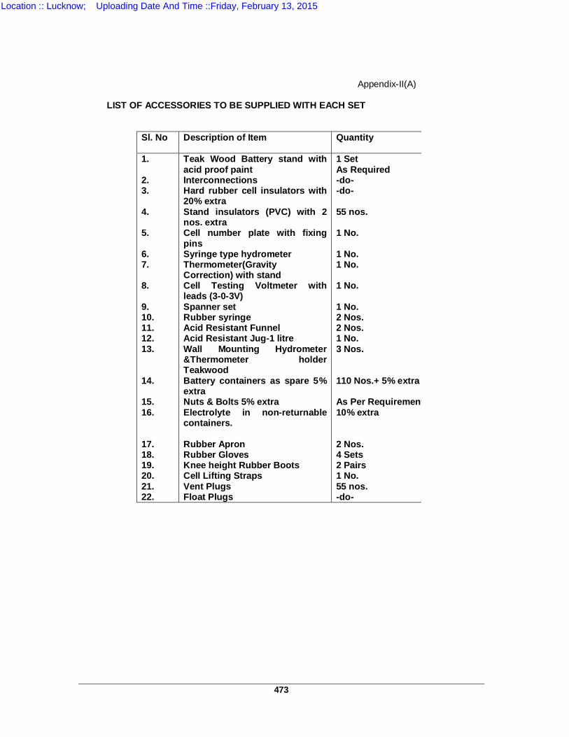
473
Appendix-II(A) LIST OF ACCESSORIES TO BE SUPPLIED WITH EACH SET
Sl. No Description of Item Quantity
1. 2. 3. 4. 5. 6. 7. 8. 9. 10. 11. 12. 13. 14. 15. 16. 17. 18. 19. 20. 21. 22.
Teak Wood Battery stand with acid proof paint Interconnections Hard rubber cell insulators with 20% extra Stand insulators (PVC) with 2 nos. extra Cell number plate with fixing pins Syringe type hydrometer Thermometer(Gravity Correction) with stand Cell Testing Voltmeter with leads (3-0-3V) Spanner set Rubber syringe Acid Resistant Funnel Acid Resistant Jug-1 litre Wall Mounting Hydrometer &Thermometer holder Teakwood Battery containers as spare 5% extra Nuts & Bolts 5% extra Electrolyte in non-returnable containers. Rubber Apron Rubber Gloves Knee height Rubber Boots Cell Lifting Straps Vent Plugs Float Plugs
1 Set As Required -do- -do- 55 nos. 1 No. 1 No. 1 No. 1 No. 1 No. 2 Nos. 2 Nos. 1 No. 3 Nos. 110 Nos.+ 5% extra As Per Requirement plus10% extra 2 Nos. 4 Sets 2 Pairs 1 No. 55 nos. -do-
Location :: Lucknow; Uploading Date And Time ::Friday, February 13, 2015
474
TS-10(B) TECHNICAL SPECIFICATIONS FOR 110/30A BATTERY
CHARGERS AND 110V/ 30A DC DISTRIBUTION BOARDS 1.0 REQUIREMENT OF BATTERY CHARGER 1.1 TYPE & RATING Each battery charger shall be of 3 phase type which must be able to meet
the above requirement plus 20 Amps station load current on both float and boost charging modes with a voltage variation from 350 V to 470 V A.C. 50 Hz 5% separately or simultaneously.
The charger shall be stand-alone, floor mounted indoor type. The panels
shall consist of fabricated sheet steel enclosures on the sides, front, rear and top. The rear door of panel shall be in the form of lockable, hinged tight fitting flap door which should close and open without keys. The front and rear sheets shall be folded construction for providing rigidity and strength (without using any frame works or screwed & bolted sheet steel sections) of not less than 14 SWG. All the switches, knob should be such mounted that only their operating handles protrude out of the panel. Suitable support channels shall be provided inside the cubicle. The charger unit will be completely vermin proof and neoprene gaskets will be provided around the edges of the door.
Important identifications/ markings shall be made on anodized plate with
etching process (not with screening process) which shall be riveted. All screws, nuts and bolts shall be rust proof and spring washers shall be
provided wherever required. Terminal blocks should be easily accessible and transparent flexible top
covers (easily removable) shall be provided to cover the live parts. 1.2 TECHNICAL REQUIREMENTS 1.2.1 Annunciation Following state of battery when the charger is in the must be suitably
displayed as follows: i. Battery set under Boost charge. ii. Battery set under trickle charge. iii. A.C. supply failure – Battery on load. This shall also be displayed with a reset table audio beeper /alarm
and center zero ampere meter without any scale multiplier.
Location :: Lucknow; Uploading Date And Time ::Friday, February 13, 2015
475
iv. Contactor circuit healthy. v. Battery out off indication to prevent deep discharge ( below 1.85V per
cell) in case battery is loaded for prolonged time. vi. Battery charger ON. vii. Incoming supply voltage High/Low. Annunciation supply shall be 110 V D.C. through the battery set. 1.2.2 The output of float charger shall be automatic so as to maintain float current
of 30A regulated within 01% over an output D.C. voltage between 0 to 140% , input voltage variation of 350 to 470V A.C. input frequency 50 Hz 5% and station D.C. load variation from 5 to 20A. The output voltage of 20 A station load shall be 110 V 1%.
1.2.3 The output of boost charger shall be manual, step less type with charge
current of 30A (max. limit 40 A) plus station load or 20 A. The output current shall remain constant ( 30A 1%) on varying station load conditions and supply input variations as per 1.3.2 above. The batteries shall automatically be placed on trickle mode upon full charge. During this change over, station D.C. load on charger shall not be interrupted. One N/o and one N/C contact ( potential free rated not more than 5A shall be provided for remote annunciation. ( Not in the scope of supplier). Additional switch and socket shall be provided for emergency D.C. light inside the control room.
1.2.4 The internal wiring of charger shall be carried out with PVC insulated multi
strand flexible copper cable or suitable size of 650V grade. Both ends of wiring shall have the numbered plastic ferrules for identification. The cubicle wiring shall be suitably branched and neatly tied up.
The cubicle should be equipped with necessary links and HRC fuses of
approved make as per annexure-II which shall be mounted on sheet steel brackets. Each fuse shall be identified with a suitable engraved label as per item 2.2 above.
The dimension of the charger cubical should preferably match with the D.C.
distribution boards. The inside surface of charger shall be painted with white synthetic paint
after properly treating the same with suitable anti rusting treatment, The outer surface of charger shall be light gray as per shade no. 631 of ISS. Only powder coating paint will be accepted.
1.2.5 PROTECTIONS Following minimum protections will be provided. i. Out put overload protection both in float and boost mode. ii. Output over voltage protection. iii. Input/Output under voltage protection ( 93 V D.C. for output ) iv. Phase failure protection ( single phase prevention). v. Output earth fault protection . vi. Trickle charging system failure. The battery if under full charge
should be prevented from connecting with the boost charger in case of failure of trickle charging circuit.
Location :: Lucknow; Uploading Date And Time ::Friday, February 13, 2015

476
Indication circuits may be protected through a common single fuse.
1.2.6 Sufficient louvers shall be provided on the top side of the battery charger
panel and on the back door of the panel. No louvers shall be provided on sides of battery charger. Fine steel wire mesh of 16 SWG which can not be locked by the dust shall also be provided under the louvers so that any undesirable element/insects may not enter into the charger through louvers.
1.2.7 The dimensions of charger shall be as follows: a) Depth 600 mm ( can not be changed). b) Height & width shall be so kept that all the components of the
charger which has to be mounted on the sides of the charger panels, may be accommodated suitably & nicely so that no problem arises during maintenance and removal/replacement. However, height & width shall not be in any case less than 1500 mm respectively .
1.2.8 Any scratch in the paint even during transit shall be attended at site.
therefore, packing should be made in such a way that panel may reach the destination without scratches/ damages in the paint.
1.2.9 Every marking/ identification of any component/any circuit shell be made on
anodized plate (not on plastic sheet) prepared with itching process (not with screening process/ or paint) and should be reverted .
1.2.10 All internal wiring of the charging unit shall be carried out with PVC
insulated Multistoried/ single strand cable of 650 V grade. Both ends of each wire shall be, marked with good quality ferrules. All wires should be suitably bunched and clamped on suitable metallic support to give straight line /90 turning appearance.
1.3 Fuse Each semi-conductor and thyristor shell be supervised by separate fuse
and relays in addition to this all circuits shall also be supervised with individual fuses. All fuses may be numbered on metallic sheet ( not with sticker etc. ) and number should be so clearly put under each fuse, so that it may be easily readable by a skilled man and their annunciation LED & relay should also be given same number duly marked on it ( refer drawing enclosed at annexure-I) in a similar fashion. The size & rating of the fuse strip ( auxiliary fuse) shall be fixed by UPPTCL later on the recommendation of successful bidder.
1.3.1 ALL HRC FUSES WILL BE OF APPROVED MAKE AND
ALL FUSES WILL BE SUPERVISED BY SEPARATE AUDIOVISUAL ANNUNCIATION.
1.4 All annunciation fuses ( auxiliary fuses ) shall be placed in side the panel. 1.5 Aesthetic view may also be kept in mind while placing the switches, meters
on front panel or inside the panel.
Location :: Lucknow; Uploading Date And Time ::Friday, February 13, 2015

477
1.6 The dimensions of the charger cubicle should match with that of D.C.
distribution board. The outside surface of the cubicle shall be synthetic enamel painted in light grey as per shade no. 631 of ISS. The inside surface of the cubicle shall be painted with white synthetic enamel paint. Before paining the cubicle surface should be properly treated to make it rust resistant.
1.7 The charger cubicle shall be delivered complete with all relays, instruments,
switches, indicating lamps and other equipments duly mounted. 1.8 In order to keep battery available to meet any heavy load condition when
boost charging is on, a suitably selected no. of the cells of the battery ( 42nd cell ) should under all conditions be connected to the load through 4 nos. blocking diodes, connected in series and parallel combinations. Each of these diodes should independently provide necessary blocking.
1.9 Under the normal operation the boost charging and float charging of the
battery should be done by the boast charger and float charger circuits respectively. However, a provision should be made for an emergency operation under which it should be made for an emergency operation under which it should be possible to use the boost charger circuit for the purpose of trickle charging of battery and also supplying simultaneously the continuous load of the substation equipment.
2.0 The drawings for plate No. 1,2,3& 4 with a proposed list of Do’s and Don’t
shall be submitted along with drawing referred under clause 7.20 for approval, UPPCTL decision shall be final.
2.1 Special arrangements have to be made so that two numbers of battery sets
can be charged (boost charging) one by one through a special selector switch on boost charging section.
2.2 After boost charging both the batteries of 30A charger have to be
transferred on float charging for trickle charging. 2.3 For 30A charger, provision shall be such that during the period when either
of the battery is in boost charging, other battery should be on trickle charge and also should be in the circuit through suitable D.C. contactor to meet any load demand to the load circuit beyond the rated capacity of the Float charger unit.
2.4 Illuminated indication of main switch positions (i)Boost charging ON (ii)
Float charging unit ON (iii) Battery I under Float ( iv) Battery IInd under float (V) both Battery under float ( vi) Battery Ist under Boost charge,(vii)Battery IInd under Boost charge should be shown on facia window on the top of the cubicle of 30A chargers.
2.5 Necessary details required for such arrangement to be indicated. Bidders
may submit their drawings along with their offers.
Location :: Lucknow; Uploading Date And Time ::Friday, February 13, 2015
478
3.0 TECHNICAL DETAILS OF IMPORTANT COMPONENTS 3.1 TRANSFORMERS Charger should be suitable for working on 3 phase A.C, supply where
phase to phase voltage may vary from 310 V to 720 V and frequency variation may be up to 3% which may occur simultaneously or separately but charger should give constant D.C. output voltage of 119 1% during float charging, station load may vary from zero to 120% of rated current.
3.1.1 FLOAT CHARGER UNIT AC transformer shall be suitably rated and should have two separate
copper windings, naturally air cooled as per ISS 2026: 1977. The capacity of transformer may be so rated that the voltage of each cell may be maintained from 2.15V to 2.2V at even maximum rated load current. Adjustment of the Voltages shall be step less.
3.1.2 BOOST CHARGER UNIT
Transformer suitably rated for full variation of voltages and frequency and
must have two separate copper winding, naturally cooled as per ISS: 2026:1977 with necessary taps on the primary winding as well as on secondary winding ( if required) for coarse and fine adjustment of the voltage in steps of 10% and 5% respectively. Capacity of the transformer may be so adjusted that the voltage of each cell of storage battery may be achieved from 1.8 Volt to 2.8 Volts.
3.1.3 Suitable interlocking switch maybe provided in the primary and secondary
windings of the transformer so that at the time of switching of the charger. It can be switched ON only when full primary & secondary winding of the transformer are in the circuit.
3.1.4 There will be separate and individual transformer for float charging and
boost charging section. 3.1.5 Transformer should be copper wound and before putting it into insulating
varnish both, it should be dehydrated and varnish should be impregnated under pressure.
3.1.6 The core of the transformer shall be GKW grade. 3.1.7 The capacity of the transformer shall be suitable for 120% of rated load.
Necessary calculation for driving the capacity of the transformer showing wire size, no. of turns, flux density core size, total weight etc, has also be enclosed along with the Bid positively.
3.2 SEMI CONDUCTORS
3.2.1 There will be two separate, full wave bridge i.e. for float charging and boost
charging.
Location :: Lucknow; Uploading Date And Time ::Friday, February 13, 2015
479
3.2.2 All semiconductors shall be provided with S.C.R. Control with a continuous
current rating suitable for full load. 3.2.3 Each semi conductor shall be mounted on separate suitably rate naturally
air cooled heat sink. 3.2.4 Calculation for selection of rating and type of heat sink shall also be
submitted along with the other details. 3.3 FLOAT CHARGING OUT PUT VOLTAGE REGULATION The out put of float charging unit shall be automatic type and D.C. voltage
shall be regulated electronically within 1% of rated output voltage (119 D.C, ) This automation shell be achieve with properly rated thyristors.
3.4 SURGE SUPPRESSOR UNIT Each semi conductor bridge shall be suitably protected with surge
suppressor unit of proper rating 3.5 RIPPLE CONTENTS 3.5.1 Float and boost unit of each charger should give smooth D.C. output with
ripple content not more that 3% without connecting any load or Battery at full rated current and A.C. Voltage of 520 Volts.
3.5.2 Choke provided in the filter circuit, it necessary, shall be of copper wire, iron
core type and shell also be supervised and protected with separate fuse and annunciation.
3.6 CURRENT LIMITING Float charging unit and boost charging unit of charger should be provided
with proper electronic current limiting features. 3.7 VOLTAGE REGULATION 3.7.1 Battery charger’s float unit should be rated for 119 volts D.C. output with a
variation of not more than 1% charger scheme should be so designed that boost charging, unit and float charging unit both will remain simultaneously and continuously.
3.7.2 Float charger should be capable to give rated D.C. Voltage automatically by
step less adjustment in such a way that the voltage of each cell may be maintained between 2.1 volt to 2.2 volts and please note load current may vary from zero to rated capacity.
3.7.3 The boost charging unit shall be so suitably rated that with the help of
coarse and fine adjustment the voltage of each cell may be achieved from 1.8 V to 2.8 volts.
3.7.4 Normally D.C. load and batteries shell always be connected with the
charger unit. The load shall be supplied by the float charging unit only and rated trickle charging current to the battery shall also be fed by the float charger unit. For a short failure of A.C. supply, D.C, load shall be fed by the batteries and after restoring the A.C. power supply battery charging shall be done by the float/boast battery charger.
Location :: Lucknow; Uploading Date And Time ::Friday, February 13, 2015
480
3.7.5 The boost charger shall automatically be connected to the bus of float
charger through a D.C. contactor when A.C main fails hence proper interlocking shall be provided with the main A.C, Supply. Also during boost charging of batteries the boost charger bus should remain isolated with float charger bus which connects the load.
3.7.6 Float and boost charger unit should be so designed that in the event of any
damage to the float charger unit, the battery shall be charged through boost charger manually and to adjust the voltage for load from battery , which may be higher then 120 V, parallel and series combination of dropping diodes may be provided, if necessary so that voltage may be adjusted accurately with course and fine arrangement ,nearest 119 V D.C. if not necessary than proposed method may be explained to achieve this requirement UPPTCL decision be final
3.7.7 The rating of dropping diodes should be sufficiently rated. 3.7.8 The range of voltage adjustment through dropping diodes may be from 148
V D.C. 115 V D.C. 3.7.9 A tap for connecting 42nd cell shall provided to the load point through four
number blocking diodes in series parallel combination.
3.7.10 D.C. volt meter ( moving coil type 144 X 144 mm) shall be provided on load side with a rotator switch capable of showing the voltages of float, boost 42 nd position, dropping diodes position and off position. The least count of the voltmeter should be 1.0 volt.
3.7.11 A.C. Supply for both the transformers shall be connected through separate
A.C. contactor with over load protection along with a main switch.
3.7.12 Moving coil type A.C. Voltmeter ( 144 x 144 mm ) shall also be provided with a rotary switch capable of showing input voltage .Least count of the voltmeter should be 1.0 volt.
3.7.13 2 Nos. separate suitable moving coil type D.C, Ammeter (141X 144 mm )
shall also be provided on float and boost charger unit with a least count of 1.0 Amp. with D.C. center zero type amp. meter in the boost charging circuit.
3.7.14 All switches used in the circuitry shall be of reliable manufacturer and of
reasonable rating ( refer annexure –II) 3.7.15 Pilot lamp showing A.C, supply shall be provided with glass lens. Color of
the lens should be red. 3.8 LED
All lamps for annunciation circuit shall be infrared red colour LEDs of high
illumination only, not less than 2.5 mm at 20 mill amp or less with a wide angle lens ( not less than 150 ) The size of the LED, if round should not be less than 5 mm and if rectangular than illuminated area should not be less than 12.7x 6.35 mm.
Location :: Lucknow; Uploading Date And Time ::Friday, February 13, 2015
481
3.9 RELAY
3.9.1 For audio alarm PLA/ OEN ( plug in type) relay should be used shall submit
his Recommendations with manufacture technical data, catalogue for finalization of rating of relays . Each thyristor/ semi-conductor of the rectifier must have individual relay for annunciation.
3.10 PUSH BUTTON
All push buttons used shall be of approved make.
4.0 PROTECTION
4.1 CURRENT LIMITING The circuit of the charger unit should be so designed the connected load
may not draw the current beyond 110% of rated current of the charger. Float charger unit should have automatic control while boost charger unit should have audio- visual indication on 110% and tripping arrangement on 120% of rated load.
4.2 OVER VOLTAGE
Over voltage protection should be provided and individual audio- visual
indication should come on each unit. The over voltage setting for float charger should be at 120 V D.C. and for boost charger 150 Volts.
4.3 UNDER VOLTAGE Under voltage protection should be provided and individual audio- visual
indication should come on both units and the setting should be 118.0 Volts D.C
5.0 ELECTRONIC CIRCUIT FOR THYRISTOR CONTROLLED MODULE 5.1.1 PRINTED CIRCUIT BOARD (P.C.B.) The P.C.B. for electronic circuit shall be made of glass epoxy cooper
laminated of thickness not less than 2.3 mm sheet and shall be of draw out module type so that at the time of servicing it can be taken out along with its presets ( pots) without de soldering any wire/ connection.
The layout drawing of the P.C,B. and size shall be got approved from
UPPTCL . the design should allow replacement at component level. 5.1.2 P.C.B. of each electronic control & power supply shall be separate & shall
be mounted with Suitable edge connectors. 5.1.3 Reference voltage sensing shall be done through IC-723/3140/324/741
metal pack only.Surface mount devices will not be accepted .Optical isolators may also be used.
5.1.4 Sensing for under voltage/ over voltage shall also be done with any of the
above IC ( Metal pack only).
Location :: Lucknow; Uploading Date And Time ::Friday, February 13, 2015

482
5.1.5 The rating & make, catalogue number of all connected electronic
components viz transistors, resistors and capacitor relays switches etc. have also to be got approved from UPPTCL, before proceeding for manufacturing.
5.1.6 UPPTCL reserves all rights to change/ suggest any component(s) as per
Purchaser’s requirement/ suitability. 6.0 ANNUNCIATION CIRCUIT
6.1 Refer clause 2.3.1
6.2 All annunciation should operate on110V D.C. output taken from output
terminal of the float charger.
6.3 There should be a push button to test all annunciation circuit and a separate push button to accept the alarm/audio indication but visual indication should not go off till the fault is removed. If there is another fault in between/before the removal of earlier fault, still the circuit should be capable of giving its audiovisual annunciation.
7.0 DRAWINGS
7.1 The scheme of charger shall be strictly as per enclosed drawing at
Annexure –I
However successful bidder can submit his proposal with full justification for any change in the drawing/rating for improvement purposes. The decision of UPPTCL shall be the final and binding on successful bidder.
7.2 DRAWING INSTRUCTION BOOKLETS, ERECTION AND
MAINTENANCE MANUALS.
6.sets of the following drawings shall be furnished for approval within one month from the date of order in quadruplicate
1. General arrangement drawing of battery charger & DCDB.
2. Schematic & Wiring drawings of battery charger & DCDB. 3. Layout and list of components showing make & ratings including the
components used on P.C.Bs 4. Service diagrams. 5. Layout of all annunciation LEDs & its description.
6. List of important DO’s& DON’TS 7. Drawing including name plate drawing. 7.3 The supplier shall submit the layout and component details of P.C.B. within
15 days of the finalization of drawings referred under para 7.2. 7.4 Any amendment suggested by the Purchaser in the layout of P.C.B and the
components shall be acceptable to the Bidder.
Location :: Lucknow; Uploading Date And Time ::Friday, February 13, 2015
483
7.5 The Bidder shall submit the service diagram of electronic circuit showing all
the important parameters viz currents and voltage within 10 days from the approval of the drawing of layout. Otherwise delivery shall not be accepted.
7.6 The Bidder shall also submit 1 set of drawing in the form of plastic
reproducible of capable of producing clear legible prints to this office (Engineer of contract).
7.7 Any other drawings if required by the Purchaser shall also be supplied by
the Bidder Without extra charges. 7.8 The Bidder shall submit ,the detailed drawing of equipment showing the
rating and make of each component (Annexure-II) including connected electronic circuit.
7.9 Any change in the drawing by the Purchaser shall have to be accepted by
the Bidder. 7.10 ANY DELAY IN APPROVAL OF DRAWINGS SHALL NOT BE THE
REASONS FOR EXTENSION IN DELIVERY The Bidder shall provide four number anodized plates of size not less than
500x300mm and plate shall be made with itching process. Plate no.1 shall consists important circuitry ,all fuses and annunciation circuit .The circuit should be so simple so that any body can understand and preliminary fault location like fuse failure etc. can be attended by a skilled man at the substation. Plate no.2 shall have important DO’s and DON’t in red colour. Plate No.1 shall be riveted in side the back door panel and plate no.2 shall be riveted on front panel . Plate no.3&4 shall have the details of annunciation.
7.11 The list of DO’s and DON’ts shall be submitted along with drawings.
All LEDs should also be mounted on anodised plate separately giving all details of indication, indicated by each LED (Para 7.2 of item 5).
7.12 Rating of all fuses used, should also be printed on separate plate showing
fuse number and 1no.fuse cartage rating to facilitate at the time of replacement of blown fuse. Drawing showing the format of this plate shall also be submitted along with the other relevant drawings.
8.0 RATING & MAKE 8.1 Make of Important components shall be as per Annexure –II . The
successful bidder can submit his proposal for the rating with full justification and manufacturers catalogue Number. The decision of UPPTCL shall be final and binding. All ratings should be of continuous type.
9.0 CHARACTER OF LOAD Bidders attention is also drawn against clause 4.3 of IS:4540:1968 character of
load is counter emf load. 10.0 MEASUREMENT OF VOLATAGE REGULATION(CLAUSE 6,7,8 IS-1540)
Bidders shall provide D.C. voltage –current characteristics for rated character of the load along with the Bid.
Location :: Lucknow; Uploading Date And Time ::Friday, February 13, 2015
484
12.0 TYPE TEST Type test shall be conducted on minimum 10% chargers or two chargers
which ever is higher at different interval and following tests shall be conducted during type tests.
i. D.C. voltage - Current characteristics. ii. Automatic voltage regulation. iii. Conversion efficiency. iv A.C. component on D.C. side. v. Temperature rise. vi High voltage test(2KV test) vii Inspection Charger shall be subject to general inspection for the
quality of work-man ship and finish. viii Auxiliary devices:-Such as contactors ,relays electronic circuits. ix In addition to above if any additional test is required by any relevant
ISS shall also be conducted. Type test shall also be conducted on transformer as per IS:2026(Part-I)1977.
13.0 ROUTINE TESTS Routine tests listed below shall be conducted on each and every charger
and DCDB along with acceptance test at manufacturers works at his cost as per latest ISS such as IS 3136-1965.
i. D.C. Voltage -Current characteristic. ii. High voltage iii. Inspection iv Auxiliary devices.
12.2.2 The battery charger capacity test may also be carried out at site at the time
of commissioning of each set.
Location :: Lucknow; Uploading Date And Time ::Friday, February 13, 2015
485
TECHNICAL SPECIFICATIONS OF D.C. DISTRIBUTION BOARDS 1.0 GENERAL The D.C. distribution board shall be similar in construction to the charger
having preferably the same height using 14SWG sheet steel. The DCDB shall have single aluminum bus bar arrangement and arrangement for connecting the out put of charger. Automatic switching of D.C.emergency light circuit in the event of A.C. failure shall also be provided.
2.0 Each D.C.D.Bs shall be provided with at least the following: i) 1no.circuit (HRC fuse protected) with suitably rates changeover
switch for charger input. ii) 1no. A.C. single phase fuse protected circuit for A.C. supply
monitoring emergency light switching and space heater. iii) 20 Nos. 20 amp.110V D.C. outgoing circuits with suitably rated
ON/OF switches(HRC fuse protected).
iv) Audio and visual indications shall be provided for tripping and under voltage D.C. (below 85% of 110V) conditions.
v) Audio and visual indication (230V AC operated ) will also be
provided for D.C.earth fault condition.
vi) Two series bulbs with center tap earthed and other ends connected to the battery shall also be provided.
3.0 DISTRIBUTION CIRCUIT FOR 200AH BATTERY 3.1 1 No. D.C. distribution board along with 1 no. charger with 1 set of
battery shall be used at each 132 KV substation.
3.2 Distribution board shall be provided with the following circuits with suitable rated Switches, protection, alarm and indication etc.
3.3 One number circuit through suitably rated change over switch with HRC
fuses for connecting respective battery charger. 3.4 1No. 230V single phase supply for connecting A.C. contactor for switching
on D.C. emergency light in the event of A.C. supply failure. 3.5 1no. D.C. emergency light for 25Amps. load with suitable rated rotary
switch HRC fuses. 3.6 20 numbers outgoing circuit for rated 15Amps.load with suitably rated
ON/OFF switches, HRC fuses. 3.7 All outgoing circuits emergency light circuit shall be supervised with
individual circuits to give audio-visual alarm for fuses failure 3.8 Suitable earth fault on D.C. system may also be provided. 3.9 Two bulbs connected in series with center point earthed and the other ends
of the two bulbs connected with the positive and negative bus bars shall also be provided.
Location :: Lucknow; Uploading Date And Time ::Friday, February 13, 2015
486
TS-11
TECHNICAL SPECIFICATION FOR 630 AMP 20KA 433 VOLTS L.T. SWITCH BOARD
1.0 STANDARDS The switchboard shall conform to following specifications latest
amendments thereof:- (a) IS-2516 (Part I&II/) Specification for alternating current C.B. Sec.I ) (b) IS-4237 General requirements for switchgear and
Controlgear for voltages not exceeding 1000 Volts.
(c) IS-6875 Control switches (Switching devices for control
and auxiliary circuits including Bidder , Control switches (Switching devices for control and auxiliary circuits including Bidder , AC & 1200V DC)
(d) IS-2705(Pt-II) Specification for current transformers. (e) IS-1248 Specification for direct acting electrical indicating
instruments. (f) IS-8623 Specification for factory built assemblies of
switchgear and controlgear for voltage up to and including 1000V AC and 1200V DC.
(g) IS-8623(Pt.-II) Particular requirements for bus bar trunking
system. (h) IS-375 Markin and arrangements for switchgear bus
bars main connections and auxiliary wiring.
2.0 LT SWITCH BOARD REQUIREMENTS 2.1 The details and arrangement for the incoming and outgoing feeders on the
L.T. switchboard shall be as per enclosed sketch no.I 2.2 Front operated L.T. switchboard shall be operative on 433 10% volts, 3-
phase, 4 wire, 50 5%Hz grounded A.C. system having a rupturing capacity of not less than 20KA at rated operating voltage.
2.3 The board shall be made of MS sheet steel clad totally enclosed ,dust and
vermin proof, 2.4 Cubicle suitable for indoor floor mounting with separate compartments for
individual feeders.
Location :: Lucknow; Uploading Date And Time ::Friday, February 13, 2015
487
2.5 Neoprene rubber gasket shall be used at all joining surfaces to achieve
dust tight and vermin proof sealing. 2.6 The switchboard shall be of sheet steel construction with M.S. sheet not
less than 3mm, thickness. Frame work shall be rigid without using any external bracings.
2.7 The switch board shall be designed to facilitate inspection/cleaning/repairs. 2.8 All equipments, bus bars with covers removed and other connections shall
be easily accessible from the back or front. No live parts of switch shall be accessible unless it has been put in ‘OFF’ position.
2.9 All switches shall be suitable for front on board operation and interlocked
with the doors. 2.10 The design of switchboard shall be such that it covers minimum floor space,
however, ample space shall be provided in the cable duct for accommodating PVC insulated aluminum conductor cables with enough space for carrying out jointing works etc.
2.11 Brass cable glands, suitable for PVC aluminium conductor cable of sizes,
as per table A&B shall be provided for all feeders. 2.12 Switches shall be placed in multitier arrangements, below with common bus
bar chamber ,the switchboard shall be complete with foundation bolts ,small wiring wherever required, earthling strips upto nearest earth bar etc. Bimetallic connectors shall be used where aluminium to copper or vice-versa connections are required.
2.13 BUS BARS i) The bus bars shall be made of copper with PVC sleeving having
rectangular cross sectional area of one square inch. These shall be adequately designed and supported to withstand the electrodynamic forces arising from a short circuit in the system.
ii) Vertical bus bars shall feed the outgoing feeders. These shall be completely
enclosed and adequately ventilated. It should be possible to work on the circuit outgoing connections with out any danger of accidental contacts with the live connections between vertical bus bar and circuit terminal.
iii) The bus bar chamber shall be adequately ventilated and shall be provided
with removable covers for easy access. The bus bars shall be PVC sleeved /taped except at T-off joints. At T-off joints sticking tape /molded tape shall be used. Connections between vertical bus bars and circuit terminals shall preferably be fully insulated or enclosed so as not to leave any exposed live parts. However these shall not be considered for any uprating of the bus bar current rating due to sleeving / taping.
iv) The bus bar should be taped with suitable colour code for ready
identification of phases.
Location :: Lucknow; Uploading Date And Time ::Friday, February 13, 2015
488
3.0 AIR CIRCUIT BREAKERS 3.1 Tripple pole air circuit breakers shall be trip free manually operated
horizontal draw out type fitted with mechanical ON and OFF indicator. 3.2 The A.C.B. should be designed for quick make and quick break operations
and shall be fitted with C.T. operated thermo magnetic release for over load and short circuit protections.
3.3 The detailed specification of air circuit breakers are as follows:- I Breaking capacity shall not be less than 20KA at rated operating voltage
and breaker shall be rated for 630Amp.continuous. II Set of mechanical interlocks with automatic safety shutter gear for
completely shielding the stationary contacts, when breaker is removed. III 1 no. auxiliary switch. IV 1no. neutral link V 1 set of contacts to give audible and visual (mechanical flag indication)
alarm in case of tripping of the circuit breaker on fault with alarm bell and cancellation switch.
VI 3nos. C.T. 400/5A for metering having accuracy class 1 and instrument
security factor 5. VII 3nos current transformer of ratio 400-200/5.15VA burden and accuracy
class 5P 10 for protection. VIII 1 no, flush mounted voltmeters. IX 1no. Voltmeter selector switch. X 1no. flush mounted ammeter suitably scaled. XI A meter selector switch. XII Suitable for 3 cores, 400sq.mm. PVC cable split type cable terminal box. XIII Push button for emergency tripping. XIV
Lable inscriptions, terminal boards and instruments fuses etc. All equipments and fuses etc. mounted on circuit breaker cubicle should be properly wired according to the equipments.
The CTs ammeter and voltmeter etc. shall be of reputed make well tried
and proven by actual use. Terminal block shall be of Kirlkoskar-Asea or Easun make.
The A.C.B. shall be of CG- Schienider/ LARSEN AND TUBRO/ ALSTOM
make.
Location :: Lucknow; Uploading Date And Time ::Friday, February 13, 2015
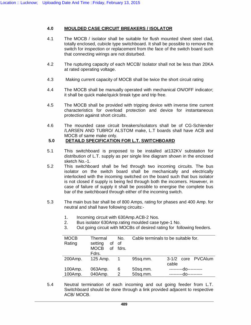
489
4.0 MOULDED CASE CIRCUIT BREAKERS / ISOLATOR 4.1 The MOCB / isolator shall be suitable for flush mounted sheet steel clad,
totally enclosed, cubicle type switchboard. It shall be possible to remove the switch for inspection or replacement from the face of the switch board such that connecting wirings are not disturbed.
4.2 The rupturing capacity of each MCCB/ Isolator shall not be less than 20KA
at rated operating voltage. 4.3 Making current capacity of MOCB shall be twice the short circuit rating 4.4 The MOCB shall be manually operated with mechanical ON/OFF indicator;
it shall be quick make/quick break type and trip free. 4.5 The MOCB shall be provided with tripping device with inverse time current
characteristics for overload protection and device for instantaneous protection against short circuits.
4.6 The mounded case circuit breakers/isolators shall be of CG-Schiender
/LARSEN AND TUBRO/ ALSTOM make, L.T boards shall have ACB and MOCB of same make only.
5.0 DETAILD SPECIFICATION FOR L.T. SWITCHBOARD 5.1 This switchboard is proposed to be installed at132KV substation for
distribution of L.T. supply as per single line diagram shown in the enclosed sketch No.-1.
5.2 This switchboard shall be fed through two incoming circuits. The bus isolator on the switch board shall be mechanically and electrically interlocked with the incoming switched on the board such that bus isolator is not closed if supply is being fed through both the incomers. However, in case of failure of supply it shall be possible to energise the complete bus bar of the switchboard through either of the incoming switch.
5.3 The main bus bar shall be of 800 Amps, rating for phases and 400 Amp. for
neutral and shall have following circuits:- 1. Incoming circuit with 630Amp.ACB-2 Nos. 2. Bus isolator 630Amp.rating moulded case type-1 No. 3. Out going circuit with MOCBs of desired rating for following feeders. MOCB
Rating Thermal setting of MOCB of Fdrs.
No. of fdrs.
Cable terminals to be suitable for.
200Amp. 125 Amp. 1 95sq.mm. 3-1/2 core PVCAlum cable
100Amp. 063Amp. 6 50sq.mm. ---------do---------- 100Amp. 040Amp. 2 50sq.mm. ---------do---------- 5.4 Neutral termination of each incoming and out going feeder from L.T.
Switchboard should be done through a link provided adjacent to respective ACB/ MOCB.
Location :: Lucknow; Uploading Date And Time ::Friday, February 13, 2015
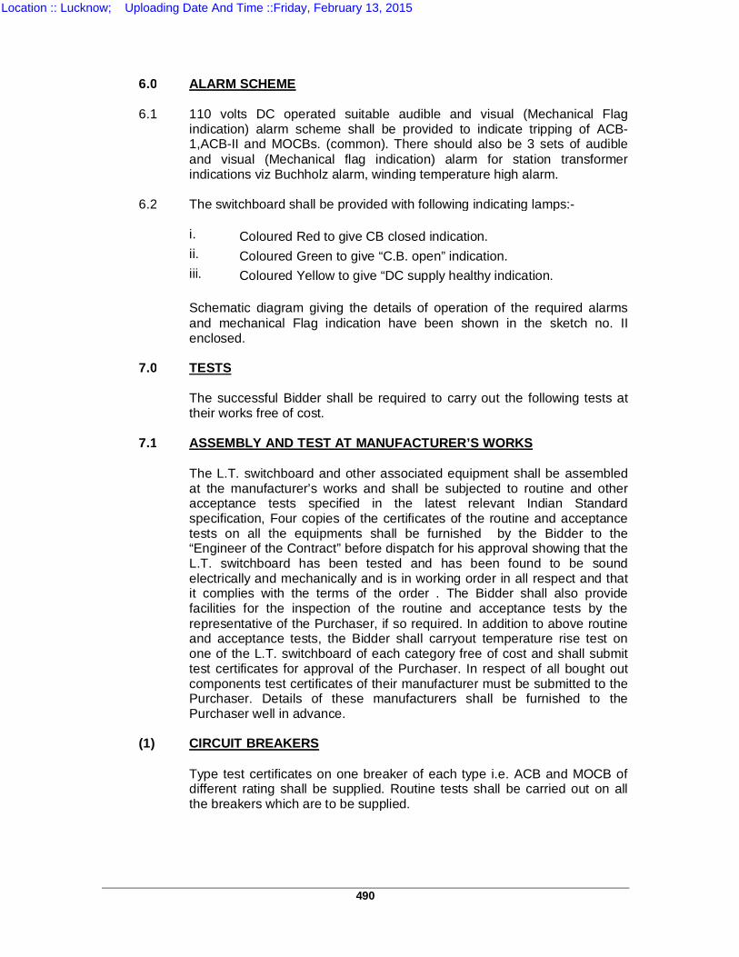
490
6.0 ALARM SCHEME 6.1 110 volts DC operated suitable audible and visual (Mechanical Flag
indication) alarm scheme shall be provided to indicate tripping of ACB-1,ACB-II and MOCBs. (common). There should also be 3 sets of audible and visual (Mechanical flag indication) alarm for station transformer indications viz Buchholz alarm, winding temperature high alarm.
6.2 The switchboard shall be provided with following indicating lamps:- i. Coloured Red to give CB closed indication. ii. Coloured Green to give “C.B. open” indication. iii. Coloured Yellow to give “DC supply healthy indication. Schematic diagram giving the details of operation of the required alarms
and mechanical Flag indication have been shown in the sketch no. II enclosed.
7.0 TESTS The successful Bidder shall be required to carry out the following tests at
their works free of cost. 7.1 ASSEMBLY AND TEST AT MANUFACTURER’S WORKS The L.T. switchboard and other associated equipment shall be assembled
at the manufacturer’s works and shall be subjected to routine and other acceptance tests specified in the latest relevant Indian Standard specification, Four copies of the certificates of the routine and acceptance tests on all the equipments shall be furnished by the Bidder to the “Engineer of the Contract” before dispatch for his approval showing that the L.T. switchboard has been tested and has been found to be sound electrically and mechanically and is in working order in all respect and that it complies with the terms of the order . The Bidder shall also provide facilities for the inspection of the routine and acceptance tests by the representative of the Purchaser, if so required. In addition to above routine and acceptance tests, the Bidder shall carryout temperature rise test on one of the L.T. switchboard of each category free of cost and shall submit test certificates for approval of the Purchaser. In respect of all bought out components test certificates of their manufacturer must be submitted to the Purchaser. Details of these manufacturers shall be furnished to the Purchaser well in advance.
(1) CIRCUIT BREAKERS Type test certificates on one breaker of each type i.e. ACB and MOCB of
different rating shall be supplied. Routine tests shall be carried out on all the breakers which are to be supplied.
Location :: Lucknow; Uploading Date And Time ::Friday, February 13, 2015
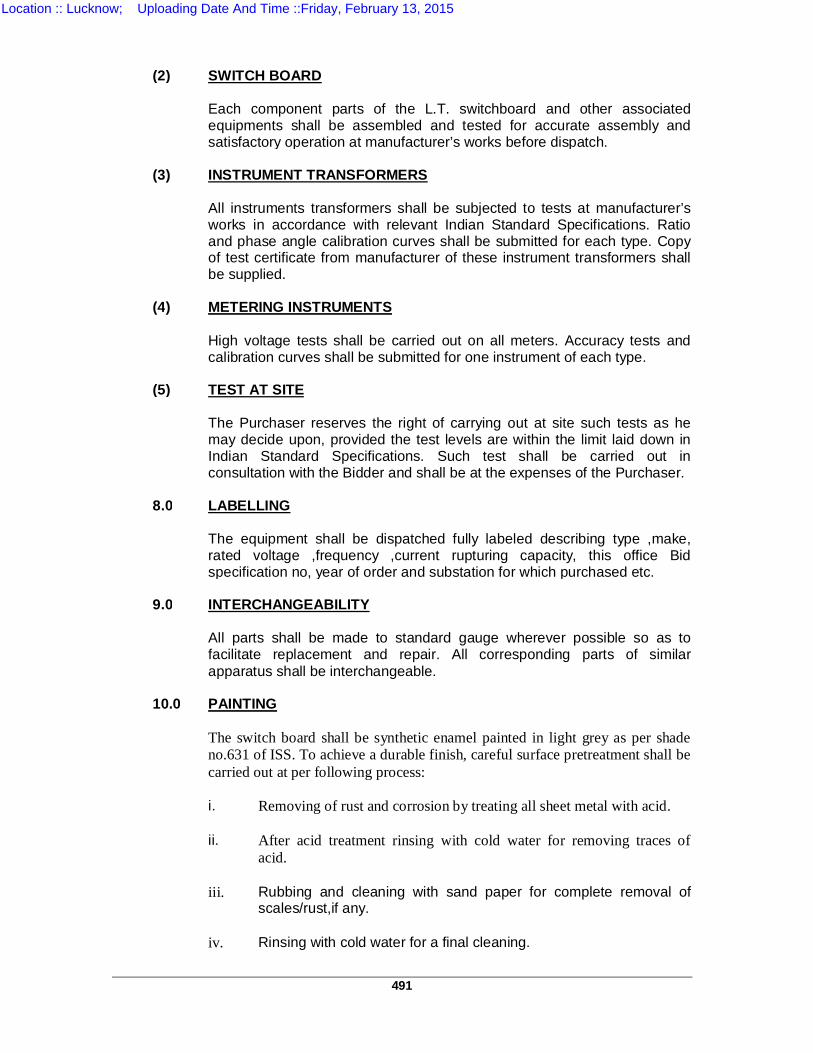
491
(2) SWITCH BOARD Each component parts of the L.T. switchboard and other associated
equipments shall be assembled and tested for accurate assembly and satisfactory operation at manufacturer’s works before dispatch.
(3) INSTRUMENT TRANSFORMERS All instruments transformers shall be subjected to tests at manufacturer’s
works in accordance with relevant Indian Standard Specifications. Ratio and phase angle calibration curves shall be submitted for each type. Copy of test certificate from manufacturer of these instrument transformers shall be supplied.
(4) METERING INSTRUMENTS High voltage tests shall be carried out on all meters. Accuracy tests and
calibration curves shall be submitted for one instrument of each type. (5) TEST AT SITE The Purchaser reserves the right of carrying out at site such tests as he
may decide upon, provided the test levels are within the limit laid down in Indian Standard Specifications. Such test shall be carried out in consultation with the Bidder and shall be at the expenses of the Purchaser.
8.0 LABELLING The equipment shall be dispatched fully labeled describing type ,make,
rated voltage ,frequency ,current rupturing capacity, this office Bid specification no, year of order and substation for which purchased etc.
9.0 INTERCHANGEABILITY All parts shall be made to standard gauge wherever possible so as to
facilitate replacement and repair. All corresponding parts of similar apparatus shall be interchangeable.
10.0 PAINTING The switch board shall be synthetic enamel painted in light grey as per shade
no.631 of ISS. To achieve a durable finish, careful surface pretreatment shall be carried out at per following process:
i. Removing of rust and corrosion by treating all sheet metal with acid. ii. After acid treatment rinsing with cold water for removing traces of
acid. iii. Rubbing and cleaning with sand paper for complete removal of
scales/rust,if any. iv. Rinsing with cold water for a final cleaning.
Location :: Lucknow; Uploading Date And Time ::Friday, February 13, 2015
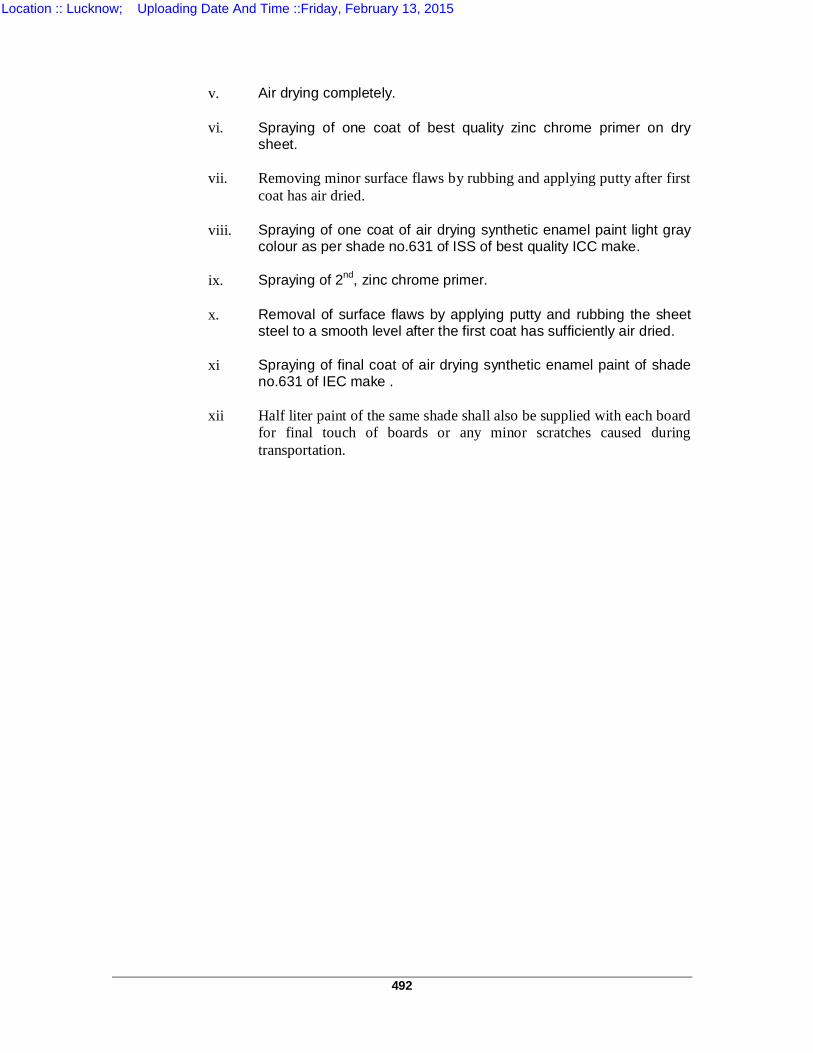
492
v. Air drying completely. vi. Spraying of one coat of best quality zinc chrome primer on dry
sheet. vii. Removing minor surface flaws by rubbing and applying putty after first
coat has air dried. viii. Spraying of one coat of air drying synthetic enamel paint light gray
colour as per shade no.631 of ISS of best quality ICC make. ix. Spraying of 2nd, zinc chrome primer. x. Removal of surface flaws by applying putty and rubbing the sheet
steel to a smooth level after the first coat has sufficiently air dried. xi Spraying of final coat of air drying synthetic enamel paint of shade
no.631 of IEC make . xii Half liter paint of the same shade shall also be supplied with each board
for final touch of boards or any minor scratches caused during transportation.
Location :: Lucknow; Uploading Date And Time ::Friday, February 13, 2015

493
TS – 12
TECHNICAL SPECIFICATION OF 33 KV 10 MVAR CAPACITOR BANK
1.0 TECHNICAL SPECIFICATIONS 1.1 REQUIREMENT AND SCOPE
1.1.1 This specification covers the design, manufacture, assembly, testing at
manufacturer’s work’s, supply, delivery, test and commissioning on supervisory basis of the following category of complete capacitor bank and associated equipments, supporting structures as specified and spares in accordance with the specifications as detailed hereinafter:-
“10 MVAR, 3- phase capacitor having internal fuse protection units and suitable
for installation on 33KV Bus-bars having highest system voltage 36KV. The rated continuous output of 10 MVAR, 33KV Bank shall be 13.26 MVAR at 38KV.”
1.1.2 Capacitor Bank alongwith mounting racks shall be suitable for mounting on
plinth in outdoor switchyard. Switching Reactors shall also be suitable for mounting on plinth. However, elevating steel structures for these, duly hot galvanized and complete with bolts and nuts and foundation bolts and nuts be also quoted as OPTIONAL ITEM. Circuit breakers shall be offered complete with mounting structures. Other required associated equipments like be CTs/ NCTs/ VTs/ Isolators etc. are to be offered without mounting structure but these shall be suitable for mounting on UPPTCL structure as per applicable drawings enclosed.
1.1.3 Required inter-connecting materials, insulators& support insulators, requisite
number of bi-metallic terminal connectors, junction boxes, bolts and nuts, foundation and fixing bolts & nuts and other auxliaries and accessories etc. shall form a part supply and prices of such items and auxliaries and accessories shall included in the prices offered for the equipments .
1.1.4 Capacitor banks shall have internal fuse protection units.
1.1.5 Capacitor banks shall be in two double star formation each double star
protected through separate one number Neutral Current Transformer (NCT)..
1.1.6 In UPPTCL system, height of gantry as well as width of bay for 33KV bus-bars are 6.0 meters. Tenderers are advised to keep this aspect in mind while offering so that no problem is faced in electrical clearances and carrying out jumpring work and electrical connections. The height of supporting structures may be considered 2.75 meters from the ground level as per enclosed drawings.
1.1.7 Detailed dimensioned layout plan and sectional elevation drawings showing the
arrangement of capacitor bank along- with associated equipments is necessary for submission with the tender. If such drawings are not submitted with the tender, the offer is liable to be rejected.
Location :: Lucknow; Uploading Date And Time ::Friday, February 13, 2015
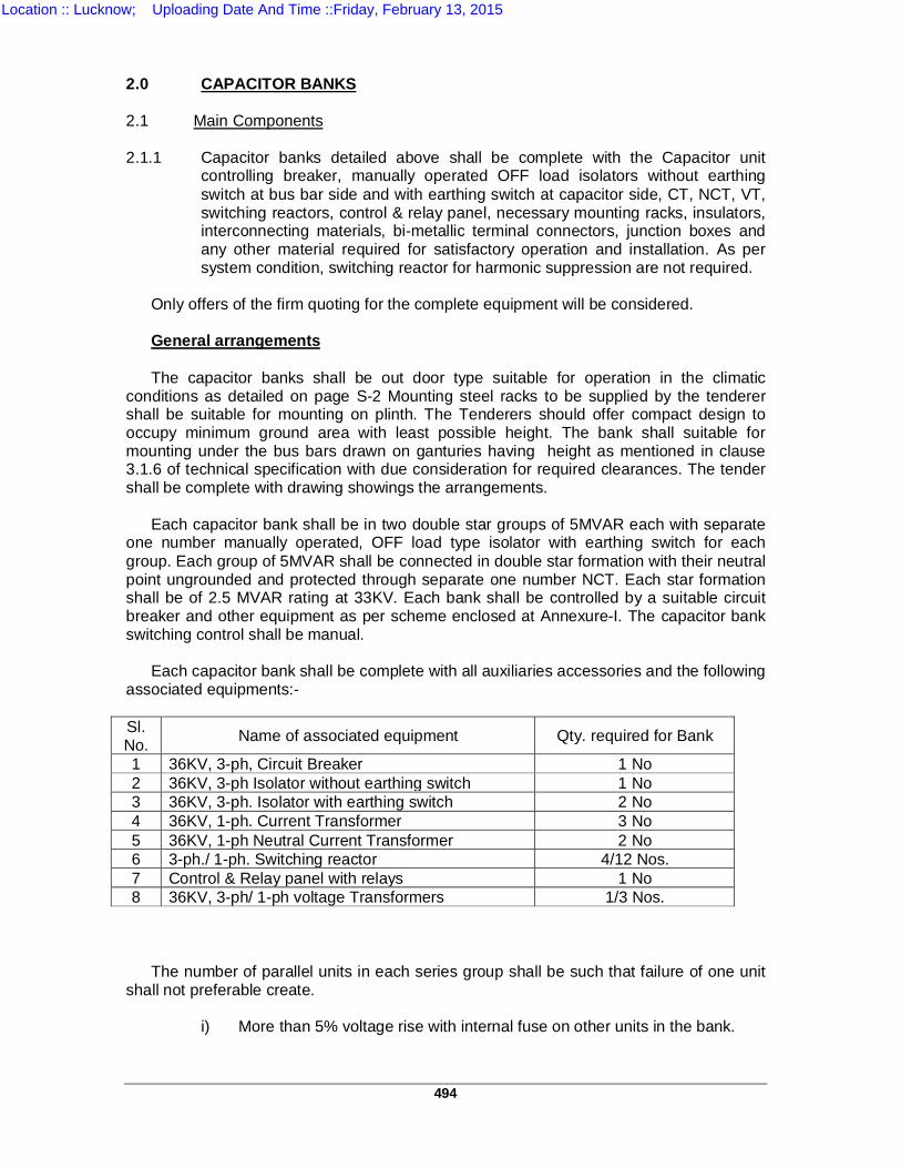
494
2.0 CAPACITOR BANKS 2.1 Main Components 2.1.1 Capacitor banks detailed above shall be complete with the Capacitor unit
controlling breaker, manually operated OFF load isolators without earthing switch at bus bar side and with earthing switch at capacitor side, CT, NCT, VT, switching reactors, control & relay panel, necessary mounting racks, insulators, interconnecting materials, bi-metallic terminal connectors, junction boxes and any other material required for satisfactory operation and installation. As per system condition, switching reactor for harmonic suppression are not required.
Only offers of the firm quoting for the complete equipment will be considered. General arrangements The capacitor banks shall be out door type suitable for operation in the climatic conditions as detailed on page S-2 Mounting steel racks to be supplied by the tenderer shall be suitable for mounting on plinth. The Tenderers should offer compact design to occupy minimum ground area with least possible height. The bank shall suitable for mounting under the bus bars drawn on ganturies having height as mentioned in clause 3.1.6 of technical specification with due consideration for required clearances. The tender shall be complete with drawing showings the arrangements. Each capacitor bank shall be in two double star groups of 5MVAR each with separate one number manually operated, OFF load type isolator with earthing switch for each group. Each group of 5MVAR shall be connected in double star formation with their neutral point ungrounded and protected through separate one number NCT. Each star formation shall be of 2.5 MVAR rating at 33KV. Each bank shall be controlled by a suitable circuit breaker and other equipment as per scheme enclosed at Annexure-I. The capacitor bank switching control shall be manual. Each capacitor bank shall be complete with all auxiliaries accessories and the following associated equipments:- Sl. No. Name of associated equipment Qty. required for Bank
1 36KV, 3-ph, Circuit Breaker 1 No 2 36KV, 3-ph Isolator without earthing switch 1 No 3 36KV, 3-ph. Isolator with earthing switch 2 No 4 36KV, 1-ph. Current Transformer 3 No 5 36KV, 1-ph Neutral Current Transformer 2 No 6 3-ph./ 1-ph. Switching reactor 4/12 Nos. 7 Control & Relay panel with relays 1 No 8 36KV, 3-ph/ 1-ph voltage Transformers 1/3 Nos.
The number of parallel units in each series group shall be such that failure of one unit shall not preferable create.
i) More than 5% voltage rise with internal fuse on other units in the bank.
Location :: Lucknow; Uploading Date And Time ::Friday, February 13, 2015
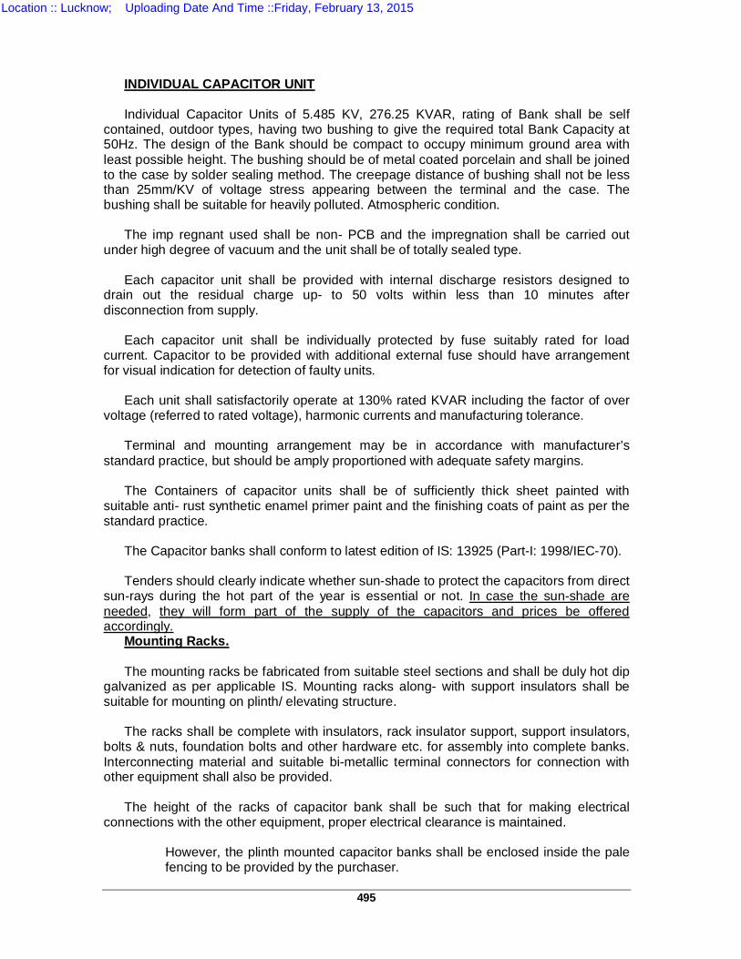
495
INDIVIDUAL CAPACITOR UNIT Individual Capacitor Units of 5.485 KV, 276.25 KVAR, rating of Bank shall be self contained, outdoor types, having two bushing to give the required total Bank Capacity at 50Hz. The design of the Bank should be compact to occupy minimum ground area with least possible height. The bushing should be of metal coated porcelain and shall be joined to the case by solder sealing method. The creepage distance of bushing shall not be less than 25mm/KV of voltage stress appearing between the terminal and the case. The bushing shall be suitable for heavily polluted. Atmospheric condition.
The imp regnant used shall be non- PCB and the impregnation shall be carried out under high degree of vacuum and the unit shall be of totally sealed type. Each capacitor unit shall be provided with internal discharge resistors designed to drain out the residual charge up- to 50 volts within less than 10 minutes after disconnection from supply. Each capacitor unit shall be individually protected by fuse suitably rated for load current. Capacitor to be provided with additional external fuse should have arrangement for visual indication for detection of faulty units. Each unit shall satisfactorily operate at 130% rated KVAR including the factor of over voltage (referred to rated voltage), harmonic currents and manufacturing tolerance.
Terminal and mounting arrangement may be in accordance with manufacturer’s standard practice, but should be amply proportioned with adequate safety margins.
The Containers of capacitor units shall be of sufficiently thick sheet painted with suitable anti- rust synthetic enamel primer paint and the finishing coats of paint as per the standard practice.
The Capacitor banks shall conform to latest edition of IS: 13925 (Part-I: 1998/IEC-70).
Tenders should clearly indicate whether sun-shade to protect the capacitors from direct sun-rays during the hot part of the year is essential or not. In case the sun-shade are needed, they will form part of the supply of the capacitors and prices be offered accordingly. Mounting Racks. The mounting racks be fabricated from suitable steel sections and shall be duly hot dip galvanized as per applicable IS. Mounting racks along- with support insulators shall be suitable for mounting on plinth/ elevating structure. The racks shall be complete with insulators, rack insulator support, support insulators, bolts & nuts, foundation bolts and other hardware etc. for assembly into complete banks. Interconnecting material and suitable bi-metallic terminal connectors for connection with other equipment shall also be provided. The height of the racks of capacitor bank shall be such that for making electrical connections with the other equipment, proper electrical clearance is maintained.
However, the plinth mounted capacitor banks shall be enclosed inside the pale fencing to be provided by the purchaser.
Location :: Lucknow; Uploading Date And Time ::Friday, February 13, 2015
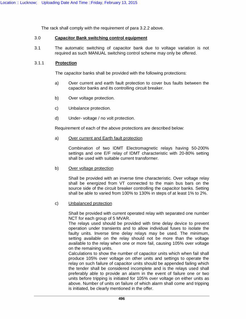
496
The rack shall comply with the requirement of para 3.2.2 above. 3.0 Capacitor Bank switching control equipment 3.1 The automatic switching of capacitor bank due to voltage variation is not
required as such MANUAL switching control scheme may only be offered. 3.1.1 Protection
The capacitor banks shall be provided with the following protections:
a) Over current and earth fault protection to cover bus faults between the
capacitor banks and its controlling circuit breaker. b) Over voltage protection. c) Unbalance protection. d) Under- voltage / no volt protection.
Requirement of each of the above protections are described below:
a) Over current and Earth fault protection Combination of two IDMT Electromagnetic relays having 50-200%
settings and one E/F relay of IDMT characteristic with 20-80% setting shall be used with suitable current transformer.
b) Over voltage protection Shall be provided with an inverse time characteristic. Over voltage relay
shall be energized from VT connected to the main bus bars on the source side of the circuit breaker controlling the capacitor banks. Setting shall be able to varied from 100% to 130% in steps of at least 1% to 2%.
c) Unbalanced protection Shall be provided with current operated relay with separated one number
NCT for each group of 5 MVAR. The relays used should be provided with time delay device to prevent operation under transients and to allow individual fuses to isolate the faulty units. Inverse time delay relays may be used. The minimum, setting available on the relay should not be more than the voltage available to the relay when one or more fail, causing 105% over voltage on the remaining units. Calculations to show the number of capacitor units which when fail shall produce 105% over voltage on other units and settings to operate the relay on such failure of capacitor units should be appended failing which the tender shall be considered incomplete and is the relays used shall preferably able to provide an alarm in the event of failure one or two units before tripping is initiated for 105% over voltage on either units as above. Number of units on failure of which alarm shall come and tripping is initiated, be clearly mentioned in the offer.
Location :: Lucknow; Uploading Date And Time ::Friday, February 13, 2015
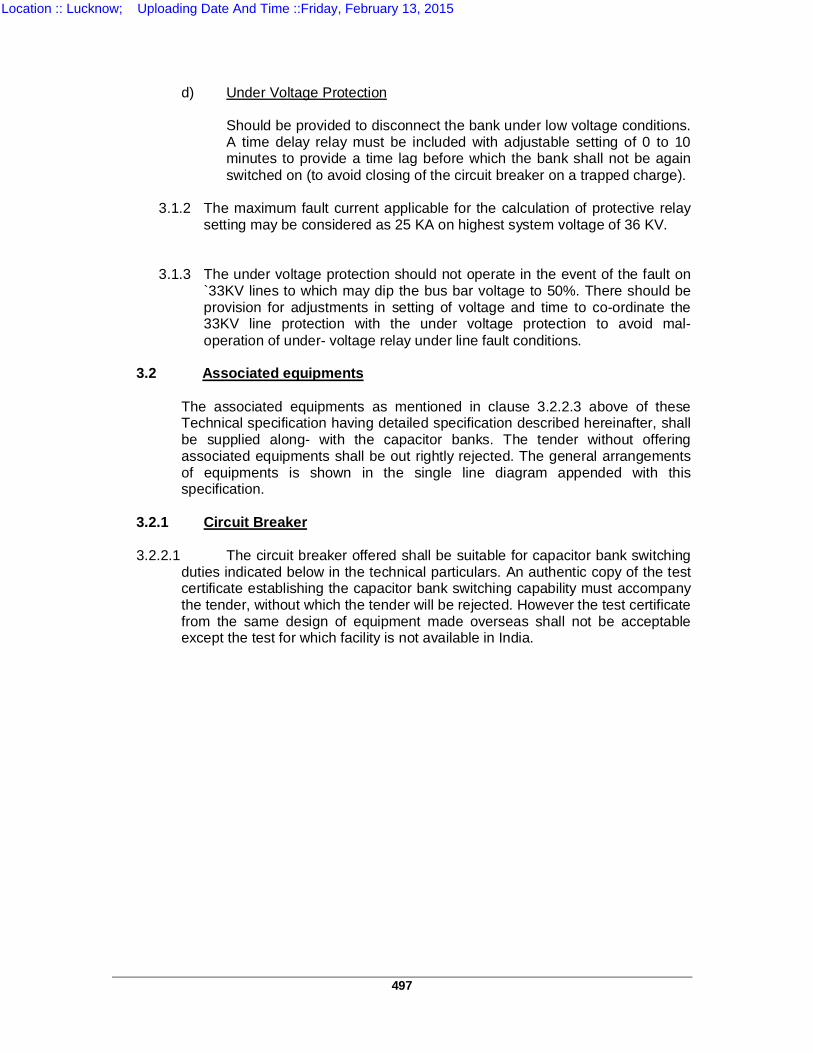
497
d) Under Voltage Protection
Should be provided to disconnect the bank under low voltage conditions. A time delay relay must be included with adjustable setting of 0 to 10 minutes to provide a time lag before which the bank shall not be again switched on (to avoid closing of the circuit breaker on a trapped charge).
3.1.2 The maximum fault current applicable for the calculation of protective relay setting may be considered as 25 KA on highest system voltage of 36 KV.
3.1.3 The under voltage protection should not operate in the event of the fault on `33KV lines to which may dip the bus bar voltage to 50%. There should be provision for adjustments in setting of voltage and time to co-ordinate the 33KV line protection with the under voltage protection to avoid mal- operation of under- voltage relay under line fault conditions.
3.2 Associated equipments
The associated equipments as mentioned in clause 3.2.2.3 above of these
Technical specification having detailed specification described hereinafter, shall be supplied along- with the capacitor banks. The tender without offering associated equipments shall be out rightly rejected. The general arrangements of equipments is shown in the single line diagram appended with this specification.
3.2.1 Circuit Breaker
3.2.2.1 The circuit breaker offered shall be suitable for capacitor bank switching
duties indicated below in the technical particulars. An authentic copy of the test certificate establishing the capacitor bank switching capability must accompany the tender, without which the tender will be rejected. However the test certificate from the same design of equipment made overseas shall not be acceptable except the test for which facility is not available in India.
Location :: Lucknow; Uploading Date And Time ::Friday, February 13, 2015
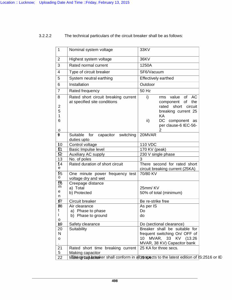
498
3.2.2.2 The technical particulars of the circuit breaker shall be as follows:
2516 or IEC recommendation No. 5
The circuit breaker shall conform in all respects to the latest edition of IS:2516 or IEC recommendation no. 56.
1 Nominal system voltage 33KV
2 Highest system voltage 36KV 3 Rated normal current 1250A 4 Type of circuit breaker SF6/Vacuum 5 System neutral earthing Effectively earthed 6 Installation Outdoor 7 Rated frequency 50 Hz 8 Rated short circuit breaking current
at specified site conditions i) rms value of AC
component of the rated short circuit breaking current 25 KA
ii) DC component as per clause-6 IEC-56-2
9 Suitable for capacitor switching duties upto
20MVAR
10 Control voltage 110 VDC 11 Basic Impulse level 170 KV (peak) 12 Auxiliary AC supply 230 V single phase 13 No. of poles 3 14 Rated duration of short circuit There second for rated short
circuit breaking current (25KA) 15 One minute power frequency test
voltage dry and wet 70/80 KV
16 Creepage distance a) Total b) Protected
25mm/ KV 50% of total (minimum)
17 Circuit breaker Be re-strike free 18 Air clearance
a) Phase to phase b) Phase to ground
As per IS Do do
19 Safety clearance Do (sectional clearance) 20 Suitability Breaker shall be suitable for
frequent switching On/ OFF of 10 MVAR, 33 KV (13.26 MVAR, 38 KV) Capacitor bank
21 Rated short time breaking current Making capacitor
25 KA for three secs.
22 Making capacitor 35 KA
Location :: Lucknow; Uploading Date And Time ::Friday, February 13, 2015
499
3.2.2.3 General
i) The circuit breaker shall be outdoor type suitable for rapid and smooth interruption of current under all condition, completely suppressing all undesirable phenomenon under the most severe and persistent short circuit conditions or when interrupting mall current or leading or lagging reactive currents.
ii) The circuit breaker shall be free from re- strike iii) The circuit breaker shall be capable of performing its specified duties at
its full rated values for a period of 3 year without any adjustment / maintenance etc. for correct operation i.e., no dis-assembly to the breaker should be done during this period.
3.2.2.4 Mounting
The circuit breaker shall be offered with necessary galvanized supporting steel
structures along –with nuts and bolts. The prices of necessary structure should be included in the price of circuit breaker.
3.2.2.6 Bushing and Insulators The basic level of the bushing and insulating porcelains should be as specified
and they should preferably be suitable for installation in heavily polluted atmosphere having creepage distance of not less than 900 mm as per relevant ISS. The porcelain used should be homogenous and free from cavities or other flaws. Bushings should be designed to have ample insulation, mechanical strength and rigidity for satisfactory operation under the conditions specified. All bushings of identical ratings should be interchangeable. The puncture strength of the bushings should be greater than the flashover valve.
3.2.2.7 Operating Mechanism i) The circuit breaker should be suitable for remote control from the control
room and in addition there should be provision for local electrical and manual operation of circuit breaker.
ii) The circuit breakers should have a mechanical ‘Open/Close’ indicator in
addition to the facilities for remote electrical indication.
iii) The operating mechanism should be of the motor operated or pneumatically operated type by electric control under normal operation. The mechanism should be strong, positive, and quick in action and should be removable without disturbing other parts of the circuit breaker. The mechanism and breaker should be such that the failure of any part of the mechanism will not prevent tripping and will not cause tripping or closing operation. The mechanism should be trip free electrically and mechanically. All working parts in the mechanism should be corrosion resistant material and all bearings which require greasing should be equipped with pressure grease fittings. A suitable anti pumping feature should be incorporated in the breaker.
Location :: Lucknow; Uploading Date And Time ::Friday, February 13, 2015
500
iv) The operating mechanism along-with its accessories should be mounted in water-proof cabinet with hinged doors located near the breaker or accommodated in the steel frame work of the breaker itself. The local control switch and the breaker position indicator should be provided in this cabinet. The circuit breaker should also be provided with means for manual operation for the maintenance purposes. An operation counter should be provided in the mechanism housing.
v) The control circuits should be designed to operate on 110 V DC and it
should be possible to adopt it to work on any other required voltages by changing the operating coils of the breaker. Closing coils should be designed to operate satisfactorily at any control voltage from 85% to 110% of the normal voltage. Tripping coils should be designed to operate satisfactorily at any control voltage from 70% to 110% of the normal voltage. However, circuit breaker when not carrying current should be capable of operating satisfactorily when the control voltage at the terminals and trip coils is less than 50% of normal voltage.
vi) A heater along with switch should be provided in the cubicle for connection
to single phase 230 V AC supply to prevent moisture condensation.
vii) A local/remote switch should be provided in the operating mechanism of the circuit breaker to cut off the DC supply to trip or close coils from remote control so that the breaker cannot be operated from remote control switch. But trip coils should be so connected that these receive a tripping command from the relays even after the remote control is disconnected.
viii) Power supply for auxiliaries will be available at 415V, 3-ph, 50 cycles. ix) Necessary cable glands for the cable of the operating mechanism should
be provided along with a large common gland plate. 3.2.2.8 Auxiliary switches
Adequate number of silver coated auxiliary switches (contact) both of the normally open and normally closed types (along-with 6 NO and 6 NC as spare) should be provided in each circuit breaker for use in the remote indication and control scheme of the circuit breaker and for providing safety inter locking. There should be provision to add a few auxiliary switches at a later date, if required.
3.2.2.9 Interlocks Provision should be made to enable suitable interlocking with the opening or closing of the isolator when the breaker is closed.
3.2.2.10 Terminal connectors Requisite number of suitable and matching bi-metallic terminal connectors shall
also be supplied along with the breaker and accordingly, the prices may be quoted.
Location :: Lucknow; Uploading Date And Time ::Friday, February 13, 2015
501
3.3.1 ISOLATORS (WITH AND WITHOUT EARTH SWITCH) 3.3.2.1 The isolators (with and without earthing switch both) shall be outdoor, manually
gang operated, double break, OFF load type, 36kV, 800 amps, 1000MVA, 3 phase, 50 Hz triple pole complying in all respects with the requirements of the latest edition of IS: 9921-1981 and complete with insulators, mechanical and electrical inter locks, bi-metallic terminal connectors suitable for ACSR panther conductor all auxiliaries and accessories.
3.3.2.2 The isolators shall be suitable for satisfactory operation with capacitors covered
by this order. The isolators are not required to operate on load, but these shall be capable of handling satisfactorily capacitive and charging current of the capacitor banks.
3.3.2.3 For position indication of isolator on the indoor control panel and for electrical
inter locking of isolator with circuit breakers and or / or other associated equipments, auxiliary supply shall be available at 110V DC.
3.3.2.4 The isolator shall be suitable for upright mounting only with the movement of
blades in a horizontal plane with supporting insulator arranged vertically. These shall be suitable for mounting and fixing on UPPTCL structure a drawing no. W- 04712. Necessary bolts and nuts for fixing the isolators on structure shall be supplied with the isolators.
3.3.2.5 The isolator shall have rotating blades and high pressure contacts. The blades
shall rotated by 90 degree from their fully closed position so that the break in distinct and clearly visible from the ground level. All clearance shall be as per latest edition of BS: 162 or corresponding IS.
3.3.2.6 The rated insulation strength of isolators and earthing switches shall not be
lower than the levels specified in Table-2 of IS: 1818-1972 with maximum temperature rise of various part of the isolators shall be as per IS: 1818-1972 with ambient temperature not exceeding 50 degree C.
3.3.2.7 The isolators shall have heavy duty, self aligning and high pressure contacts of
modern design and made out of silver plated hard-drawn electrolytic copper. All non-ferrous contact parts are to be silver plated. The blade and contacts shall be liberally designed to withstand safely the highest short circuit currents of the system.
3.3.2.8 The male and female contacts assembly and blades shall ensure the following:-
A) Electrodynamics with stand ability during short circuits without risk of repulsion of contacts.
B) Thermal withstand ability during short circuits. C) Constant contact pressure even when the live parts of the insulator stacks
are subject to tensile stress due to linear expansion of connected bus bars or flexible conductor either due to temperature variations or strong wind.
D) Wiping action during closing and opening. E) Self alignment ensuring smooth closing of the switch.
Location :: Lucknow; Uploading Date And Time ::Friday, February 13, 2015
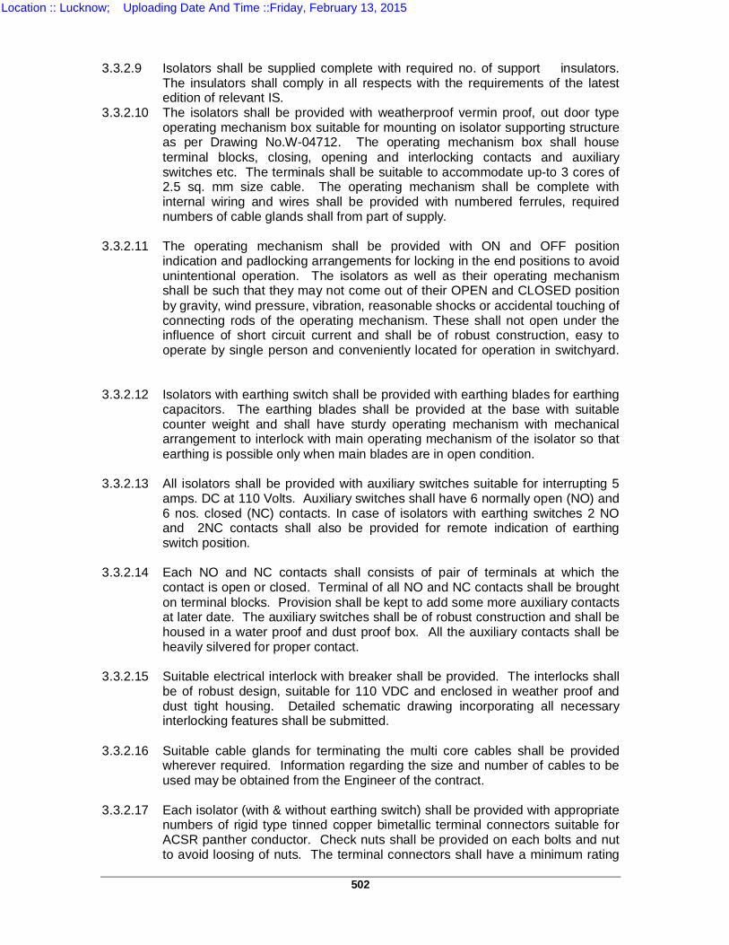
502
3.3.2.9 Isolators shall be supplied complete with required no. of support insulators.
The insulators shall comply in all respects with the requirements of the latest edition of relevant IS.
3.3.2.10 The isolators shall be provided with weatherproof vermin proof, out door type operating mechanism box suitable for mounting on isolator supporting structure as per Drawing No.W-04712. The operating mechanism box shall house terminal blocks, closing, opening and interlocking contacts and auxiliary switches etc. The terminals shall be suitable to accommodate up-to 3 cores of 2.5 sq. mm size cable. The operating mechanism shall be complete with internal wiring and wires shall be provided with numbered ferrules, required numbers of cable glands shall from part of supply.
3.3.2.11 The operating mechanism shall be provided with ON and OFF position
indication and padlocking arrangements for locking in the end positions to avoid unintentional operation. The isolators as well as their operating mechanism shall be such that they may not come out of their OPEN and CLOSED position by gravity, wind pressure, vibration, reasonable shocks or accidental touching of connecting rods of the operating mechanism. These shall not open under the influence of short circuit current and shall be of robust construction, easy to operate by single person and conveniently located for operation in switchyard.
3.3.2.12 Isolators with earthing switch shall be provided with earthing blades for earthing
capacitors. The earthing blades shall be provided at the base with suitable counter weight and shall have sturdy operating mechanism with mechanical arrangement to interlock with main operating mechanism of the isolator so that earthing is possible only when main blades are in open condition.
3.3.2.13 All isolators shall be provided with auxiliary switches suitable for interrupting 5
amps. DC at 110 Volts. Auxiliary switches shall have 6 normally open (NO) and 6 nos. closed (NC) contacts. In case of isolators with earthing switches 2 NO and 2NC contacts shall also be provided for remote indication of earthing switch position.
3.3.2.14 Each NO and NC contacts shall consists of pair of terminals at which the
contact is open or closed. Terminal of all NO and NC contacts shall be brought on terminal blocks. Provision shall be kept to add some more auxiliary contacts at later date. The auxiliary switches shall be of robust construction and shall be housed in a water proof and dust proof box. All the auxiliary contacts shall be heavily silvered for proper contact.
3.3.2.15 Suitable electrical interlock with breaker shall be provided. The interlocks shall
be of robust design, suitable for 110 VDC and enclosed in weather proof and dust tight housing. Detailed schematic drawing incorporating all necessary interlocking features shall be submitted.
3.3.2.16 Suitable cable glands for terminating the multi core cables shall be provided
wherever required. Information regarding the size and number of cables to be used may be obtained from the Engineer of the contract.
3.3.2.17 Each isolator (with & without earthing switch) shall be provided with appropriate
numbers of rigid type tinned copper bimetallic terminal connectors suitable for ACSR panther conductor. Check nuts shall be provided on each bolts and nut to avoid loosing of nuts. The terminal connectors shall have a minimum rating
Location :: Lucknow; Uploading Date And Time ::Friday, February 13, 2015
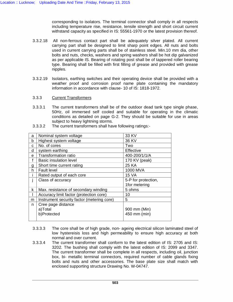
503
corresponding to isolators. The terminal connector shall comply in all respects including temperature rise, resistance, tensile strength and short circuit current withstand capacity as specified in IS: 55561-1970 or the latest provision thereof.
3.3.2.18 All non-ferrous contact part shall be adequately silver plated. All current
carrying part shall be designed to limit sharp point edges. All nuts and bolts used in current carrying parts shall be of stainless steel. Min.10 mm dia, other bolts and nuts, checks, washers and spring washers shall be hot dip galvanized as per applicable IS. Bearing of rotating post shall be of tappered roller bearing type. Bearing shall be filled with first filling of grease and provided with grease nipples.
3.3.2.19 Isolators, earthing switches and their operating device shall be provided with a
weather proof and corrosion proof name plate containing the mandatory information in accordance with clause- 10 of IS: 1818-1972.
3.3.3 Current Transformers
3.3.3.1 The current transformers shall be of the outdoor dead tank type single phase,
50Hz, oil immersed self cooled and suitable for operating in the climatic conditions as detailed on page G-2. They should be suitable for use in areas subject to heavy lightning storms.
3.3.3.2 The current transformers shall have following ratings:- a Nominal system voltage 33 KV b Highest system voltage 36 KV c No. of cores Two d system earthing Effective e Transformation ratio 400-200/1/1/A f Basic insulation level 170 KV (peak) g Short time current rating 25 KA h Fault level 1000 MVA i Rated output of each core 15 VA j Class of accuracy 5-P for protection,
1for metering k Max. resistance of secondary winding 5 ohms l Accuracy limit factor (protection core) 10
m Instrument security factor (metering core) 5 n Cree page distance
a)Total b)Protected
900 mm (Min) 450 mm (min)
3.3.3.3 The core shall be of high grade, non- ageing electrical silicon laminated steel of
low hystereisis loss and high permeability to ensure high accuracy at both normal and over current.
3.3.3.4 The current transformer shall conform to the latest edition of IS: 2705 and IS: 3202. The bushing shall comply with the latest edition of IS: 2099 and 3347. The current transformer shall be complete in all respects, including oil, junction box, bi- metallic terminal connectors, required number of cable glands fixing bolts and nuts and other accessories. The base plate size shall match with enclosed supporting structure Drawing No. W-04747.
Location :: Lucknow; Uploading Date And Time ::Friday, February 13, 2015
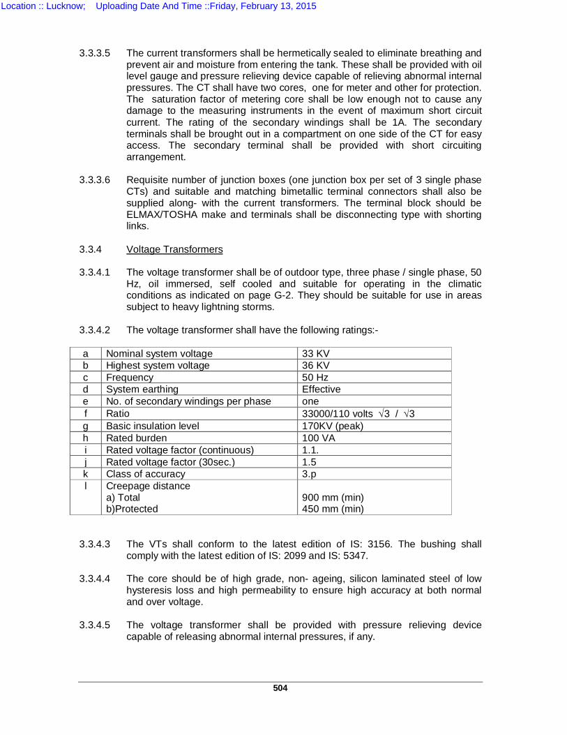
504
3.3.3.5 The current transformers shall be hermetically sealed to eliminate breathing and
prevent air and moisture from entering the tank. These shall be provided with oil level gauge and pressure relieving device capable of relieving abnormal internal pressures. The CT shall have two cores, one for meter and other for protection. The saturation factor of metering core shall be low enough not to cause any damage to the measuring instruments in the event of maximum short circuit current. The rating of the secondary windings shall be 1A. The secondary terminals shall be brought out in a compartment on one side of the CT for easy access. The secondary terminal shall be provided with short circuiting arrangement.
3.3.3.6 Requisite number of junction boxes (one junction box per set of 3 single phase
CTs) and suitable and matching bimetallic terminal connectors shall also be supplied along- with the current transformers. The terminal block should be ELMAX/TOSHA make and terminals shall be disconnecting type with shorting links.
3.3.4 Voltage Transformers 3.3.4.1 The voltage transformer shall be of outdoor type, three phase / single phase, 50
Hz, oil immersed, self cooled and suitable for operating in the climatic conditions as indicated on page G-2. They should be suitable for use in areas subject to heavy lightning storms.
3.3.4.2 The voltage transformer shall have the following ratings:- a Nominal system voltage 33 KV b Highest system voltage 36 KV c Frequency 50 Hz d System earthing Effective e No. of secondary windings per phase one f Ratio 33000/110 volts 3 / 3 g Basic insulation level 170KV (peak) h Rated burden 100 VA i Rated voltage factor (continuous) 1.1. j Rated voltage factor (30sec.) 1.5 k Class of accuracy 3.p l Creepage distance
a) Total b)Protected
900 mm (min) 450 mm (min)
3.3.4.3 The VTs shall conform to the latest edition of IS: 3156. The bushing shall
comply with the latest edition of IS: 2099 and IS: 5347. 3.3.4.4 The core should be of high grade, non- ageing, silicon laminated steel of low
hysteresis loss and high permeability to ensure high accuracy at both normal and over voltage.
3.3.4.5 The voltage transformer shall be provided with pressure relieving device
capable of releasing abnormal internal pressures, if any.
Location :: Lucknow; Uploading Date And Time ::Friday, February 13, 2015
505
3.3.4.6 The voltage transformer shall be complete in all respects including oil, bimetallic
terminal connectors, fixing bolts and nuts and other accessories. The base plate size shall match with the enclosed supporting structure drawing no. W-04747. The primary winding of the voltage Transformer shall be connected in star with neutral point solidly earthed.
3.3.4.7 The VT shall be suitable for protection as well as for metering. The secondary
shall be connected in star with neutral point solidly earthed.
3.3.4.8 Neutral Current Transformer
3.3.5.1 Two NCTs shall be required for one set of capacitor bank.
3.3.5.2 The neutral current transformer shall be as per specifications of CT except that it shall have single core, transformer ration 5/1 and accuracy class for the protection core shall 5 P 10.
3.3.5.3 Required number of suitable and matching bimetallic terminal connectors along-
with required number of cable glands shall be supplied along- with the NCTs. And accordingly the prices may be quoted.
3.3.5.4 The mounting details shall match with the supporting structure drawing No. W-
04747.
3.3.6 Control & Relay Panel
3.3.6.1 The control and relay panels shall conform in all respects to relevant Indian standards. Equipment meeting any other authoritative standard which ensures an equal or better standard than mentioned above may also be considered.
3.3.6.2 The control and relay panel shall be of floor mounted, indoor free, standing
cubicle type. The panels shall consist of fabricated sheet enclosures on the sides, front, rear and top.
The rear of the panels shall be in the form of lockable hinged flap door. The
front and rear sheets shall be of folded construction for providing rigidity and strength without using any frame work or screwed or bolted sheet steel sections. The front of the panels which accommodates most of the mountings shall be fabricated with sheet steel of thickness not less than 10 SWG. For the rest of the panel which carries no weight of the mountings, sheet steel of thickness not less than 14 SWG should be used.
3.3.6.3 The panels shall be 2250 mm high, 750 mm wide and 600 mm deep with
door lock and complete with wiring, earthing bar, fuses links, vermin proof fitments, internal panel lighting arrangement operated by a door switch, a space heater rated 100 Watt, 230 V AC with a switch, un-drilled cable gland plate, 75 mm channel iron plinth 100 mm high and accommodating following equipments suitable for 10 MVAR, 33 KV Banks as applicable:-
a) Ammeter with selector switch b) Voltmeter with selector switch c) CB control switch d) Manual control switch e) Indicating lamps
Location :: Lucknow; Uploading Date And Time ::Friday, February 13, 2015
506
f) Alarm bell g) Alarm cancellation relay h) MVAR meter i) PF Meter j) Push buttons and switches k) Relays and auxiliary relay l) Facia type annunciation scheme m) Semaphore indicator CB n) Semaphore indicator for isolator o) DC control switch ON/ OFF p) Test terminal block q) Hooter DC 110 V r) Hooter AC 230 V s) HCR fuse fittings/ links (as required) t) Space heater 100 watts, 230 VAC with switch u) Panel illuminating lamp v) Door limit switch w) Disconnecting type terminal x) Non disconnecting type terminal y) Earth bus copper z) Any other item required to make the panel complete.
3.3.6.4 All the relay should be accommodated suitable in the control panel complete
with necessary indicating instruments control switches, indicating lamps, wiring fuses links etc.
3.3.6.5 The panel shall be equipped with necessary links and HRC type fuses of good
quality which shall be mounted on sheet brackets. Each fuse shall be identified with the suitable engraved plastic lable.
3.3.6.6 The control and relay panels shall be delivered with all relay, instruments,
switches, indicating lamps etc. duly mounted.
3.3.6.7 The internal wiring of the panels shall be carried out with PVC insulated multistrand, copper, flexible cables of 650 V grade. Both ends of wire shall have the numbered plastic ferrules for identification. Panel wiring shall be suitably bunched and clamped to present a neat appearance. All panel wiring should with stand 2KV, AC,50 Hz, RMS for 1 Min. between conductors and earth.
3.3.6.8 All panel wiring terminations (but for CT and VT) for connecting external
apparatus circuit shall be neatly terminated on ordinary terminal blocks. For CT & VT termination, links terminal blocks to be used shall have links for disconnection and plugging in facility for testing purposes. The terminal shall be suitably labeled to readily identify the outgoing/ incoming wires, 20% terminal of each type shall be provided as spare in each panel for future use. The terminal block shall be ELMEX/TOSHAS make.
3.3.6.9 All equipment including relays, indicating instruments etc. shall be flush
mounted. All the mountings shall be provided on the front side. 3.3.6.10 The outside surface of the panels shall be synthetic enamel painted in light
grey as per shade no. 631 of IS. The inside surface shall be painted with white synthetic enamel paint.
Location :: Lucknow; Uploading Date And Time ::Friday, February 13, 2015
507
3.3.6.11 Each relay, auxiliary relay, instruments, lamps, switches etc. should be
identified both inside and outside the panel with suitable engraved plastic labels.
3.3.6.12 Mimic diagram and symbols showing the exact representation of the system
complete with symbols and colour strips to represent the buses, semaphore indicator etc. shall be provided in front of the control panels. The control switches shall be mounted alongwith the mimic diagram. Specific number shall be assigned to various isolators and circuit breakers on the MIMIC diagram.
3.3.6.13 Automatic semaphore indicators shall be provided for automatic indication in
the mimic diagram of the position (open or close) of isolator and circuit breakers. Semaphore indicators shall be so mounted on the mimic diagram that the close position shall complete the continuity of the mimic. Their strips shall be of the same colour as of the associated mimic.
3.3.6.14 Indicating lamps shall be miniature switch board type suitable for panel mounting with rear terminal connections lamps shall be provided with series connected resistors. The supply for these lamps be from DC station battery unless stated otherwise. Lamps covered shall be screw type unbreakable, molded from heat resisting materiel. The lamp covers, shall be colored as:
a) ‘Red’ - For indicating close position of breaker
b) ‘Green’ - For indicating open position of breaker c) ‘Blue’ - For control supply monitoring d) ‘White & amber’ - For miscellaneous indications All colour covers shall be similar and inter changeable and all lamps be of same
type and rating. Lamps shall be furnished 20% in excess of the actual number required and caps shall be furnished 10% in excess of actual number used for each colour. The indicating lamps and resistors shall withstand 120% of rated voltage on a continuous basis.
3.3.6.15 Alarm annunciation system shall be provided for the control board by means of visual and audible alarm in order to draw the attention of the operator to the abnormal operating conditions or the operation of some protective device. The annunciation equipment shall be suitable for operation on DC supply. When the breaker is tripped automatically audible annunciation shall be provided along with visual annunciation which shall be by flickering of a respective facia window provided on the panels. The tripped breaker shall be identified by the flickering the corresponding position indicating lamps. In case of other annunciation, to draw the attention of the operator to the occurrence of an abnormal operating condition and then the tripping of the circuit breaker, an audible annunciation shall be provided. The visual annunciation shall be by flickering of the respective facia window. Certain number of alarms under this category have to be time delayed with the time delay adjustment. The visual annunciation shall be provided by an annunciation facia flush mounted on the top row of the control panels. Necessary switching relay for the same shall be mounted inside the panel. The annunciator facia shall be provided with translucent glass or plastic cover plates of white colour with inscription in block letters. Alarm inscription shall be engraved on each window. Each annunciation window shall be provided with two lamps in parallel to provided safety against lamp failure. The lamps circuit shall include series resistor of adequate rating.
Location :: Lucknow; Uploading Date And Time ::Friday, February 13, 2015
508
Acknowledge” “Reset” and “Lamp Test” push buttons for the annunciation shall be provided.
3.3.6.16 Visual and audible annunciation for the failure of DC supply tro the panel shall also be provided and this annunciation shall operate on 240 volts AC supply with separate fuses. A separate voltage check relays (adjustable setting for the failure of supply shall be provided and if the failure of supply exists for more than 2 to 3 secs.) facia shall light up and the bell shall sound. A separate push button shall be provided for cancellation of this along but the facia window shall remain steadily lighted till the supply to the annunciation system is restored.
3.3.6.17 The trip circuit shall be supervised by means of relays. The scheme shall
continuously monitor the trip circuit before closing and after closing of breaker. The scheme shall detect (I) failure of trip supply (ii) open circuit of trip wiring and (iii) failure of mechanism to complete the tripping operation. The relays shall have necessary contacts to be connected to either the alarm bell or to the annunciator available in the control panel for visual and audible indication of the trip circuit.
3.3.7 Switching Reactors
3.3.7.1 The series reactor of small size is required for limiting the inrush due to parallel
switching of capacitor bank on the same bus.
3.3.7.2 The series reactors shall be of outdoor type, 15 Hz, oil cooled non-magnetically shielded, air cooled and suitable for operation in climatic conditions as indicated in page G-2. They should be suitable for use in arias subjected to heavy lightning storms.
3.3.7.3 The tenderer should offer neutral side series reactor and it must be ensured
that series reactors are capable of withstanding the short circuit currents.
3.3.7.4 Series reactor may be installed on the plinth as such foundation bolts are also to be supplied.
3.3.7.5 The series reactor shall be complete in all respects including oil, clamps, fixing
bolts and nuts, bimetallic terminal connectors and other accessories and shall conform to the latest edition of IS: 5553.
3.4 Fittings and accessories Any fittings or accessories which might not have been mentioned in the
specifications but which are usual or are necessary, required in the equipment or similar nature are to be provided by the contractor without extra cost. All equipment must be complete in all details whether mentioned in the specifications or not.
3.5 Terminal connectors Requisite number of suitable and matching bimetallic connectors shall be
supplied for all the equipments offered for supply. The connectors shall be complete with matching bolts nuts, spring washers etc. and shall be suitable for ACSR panther conductor. All ferrous parts shall be duly galvanized. For equipments requiring both horizontal as well as vertical take off, provision shall be made for both.
Location :: Lucknow; Uploading Date And Time ::Friday, February 13, 2015
509
3.6 Make Components The make of components, such as switches, relays, instruments auxiliary
transformers, fuses etc. to be used in the various equipments tendered, should invariably be given.
3.7 Guaranteed Technical Particulars
The tendered shall submit guaranteed technical particular of all equipments
including capacitor and associated equipments in the annexed schedule ‘R’ “Guaranteed Technical Particulars”.
3.8 Applicable standards The capacitor bank and the associated equipments shall conform the standards
detailed below in accordance with their latest amendments if any. a Capacitor banks IS:13925, IEC No.70 b Circuit breaker IS:2516, IEC No.56 c Isolator IS:1818, IS:9921 d CT & NCT IS:2075 e VT IS:3156, IS:3941 f Reactor IS:5553 g Bushings & insulators IS:2099, IS:3347 h Transformer oil IS:335 i Terminal connectors IS:617 j Nuts & bolts IS:1363, IS:1367 k Relays IS:3231
3.9 Capitalization of losses The guaranteed quoted losses of capacitors and series reactors shall be without
any positive tolerance and shall be capitalized as follows and accordingly for evaluating different tenders, the loading shall be made by the purchaser:- i) The dielectric losses in capacitors shall be loaded by Rs.89000/-per KW. ii) The iron losses in series reactors shall be loaded by Rs.89000/-per KW. iii) The copper losses in series reactors shall be loaded by Rs.89000/-per
KW. If during testing the guaranteed dielectric losses in capacitors, iron and copper losses in series reactors are found to exceed the guaranteed quoted values then the price reduction in accordance with the prices would be made from invoices of the successful tenderer.
3.10 Identification plate The successful tenderer is required to affix a plate on the capacitor bank and
associated equipment with the following information in addition to the rating plate:- a) Specification no. b) Year of order/manufacture c) Name of manufacture.
Location :: Lucknow; Uploading Date And Time ::Friday, February 13, 2015
510
TS-13
TECHNICAL SPECIFICATION OF 1.1 KV, PVC FRLS, UNARMOURED COPPER CONROL CABLES AND ALLUMINUM POWER CABLES
1.0 STANDARDS
The design, manufacture and testing of cables covered under this specification shall comply with following standards (with subsequent amendments thereof) unless otherwise specified :-
1. IS:1554 (Part-I) PVC insulated (Heavy duty electric cables).
2. IS:1554 (Part-II) PVC Insulated (Heavy duty) Electric Cables.
3. IS:5831 PVC Insulation and sheath of Electric Cables.
4. IS:8130 Conductors for insulated Electric Cables and Cords.
5. IS:3961 Current Ratings of Cables.
6. IS:502 Extended solid di-electric insulated power cables for rated voltage from 1 KV to 30 KV.
7. IEC-540 & 540A Test methods for insulation and sheath of electric cables and cords.
8. IEEE 383 Standard for type tests for class IE Electric Cables, field Splices and connections for nuclear power generating stations.
9. Swedish Standard SS 4241475 Class F-3
Flammability Test
10. IEC 332-I Test on electric cables under fire conditions.
11. ASTMD-2843 Standard test method for density of smoke from burning/decomposition of plastics.
12. IEC 754-I Test method for acid gas generation.
13. BICC hand book for cables in fire regarding temperature index- Chapter-6.
14. ASTMD-2863 Oxygen index and temperature index tests.
15. NEMA-WC-5 i) Accelerated water Absorption test.
ii) Dielectric strength Retention test
Location :: Lucknow; Uploading Date And Time ::Friday, February 13, 2015
511
2.0 1.1 KV GRADE FRLS CONTROL CABLES
PRINCIPAL PARAMERERS
S.No. Particulars Size of PVC, FRLS Control Cables.
2x2.5 mm2
4x2.5 mm2
6x2.5 mm2
10x2.5
mm2
1. Type of cable 1.1 KV grade, PVC, FRLS, Unarmoured control cables.
2. Standard applicable IS: 1551 (Part-I).
3. CONDUCTOR
(a) Material Plain annealed high conductivity copper as per IS:8130.
(b) Shape of conductor Solid copper having circular cross section.
(c) Size (Dia) nom. in mm. 1.78
(d) Max.m D.C. resistance of conductor of completed cable at 200C (ohm/km.)
............. 7.41 ..............
4. INSULATION
(a) Type ............... PVC Type-A of IS:5831.
(b) Thickness (Nom.) in mm. ................... 0.9 .....................
5. INNER SHEATH
(a) Type .......... PVC Type ST-1 of IS:5831
(b) Thickness (min.m) in mm. .......... 0.3 ..............
6. OUTER SHEATH
(a) Type ......... PVC Type ST-2 of IS:5831
(b) Thickness (Nom.) in mm. ......... 1.8 ...............
2.0
(10x2.5 mm2)
7. Standard drum length ....... 500 metres + 5% ......... 8. Extrusion of inner and outer sheath. In two distinct separate extrusions.
Location :: Lucknow; Uploading Date And Time ::Friday, February 13, 2015
512
2.1 Control Cables shall be 1.1 KV grade, high conductivity, solid copper
conductor, PVC insulated, extruded PVC inner sheathed and separate extruded PVC outer sheath overall having FRLS properties as per above standards, conforming to IS:1554 (Part-I)
2.2 Two distinct sheaths i.e., inner and outer should be provided in two separate
operations. Single operation sheathing shall not be accepted. The outer sheathing shall be designed to afford a high degree of mechanical protection against fire and also shall be oil, chemicals and weather resistant. Common acids, alkalies and saline solutions should not have any adverse effect on PVC sheathing materials used. The outer sheathing shall be of PVC having FRLS properties.
2.3 The Control Cables shall be suitable for running in conduits, ducts,
channels, racks and trays, covered trenches with removable covers in outdoor substations and also in ground.
2.4 CONDUCTOR The conductor shall be made from plain annealed high conductivity solid
copper having resistance and diameter specified in the technical particulars (on page TS-9).
2.5 INSULATION The PVC insulation shall be Type-A, extruded PVC 1.1 KV grade and free
from voids. The insulation shall withstand mechanical and thermal stresses under steady state and transient operating conditions. It shall be of consistent quality and free from all defects.
2.6 INNER SHEATH The inner sheath shall be of extruded PVC (Type-ST1). The sheath shall be
suitable to withstand the site conditions and the desired temperature. It shall be of min.m thickness as per technical particulars (page TS-9) and applied by a continuous process to produce a sheath of consistent quality and free from all defects.
2.7 OUTER SHEATH It should be of extruded PVC (Type ST2) having min.m thickness as per
technical particulars (page TS-9). Outer sheath shall be applied in distinct separate extrusion. It should be of consistent quality and free from all defects. Suitable additives are also applied to prevent attack by rodent and termites. The outer sheathing must be fire retardant and low smoke type.
2.8 NUMBERING OF THE CORES The colour code of cores shall be as per IS: 1554 and also each light grey
core of 6 and 10 core cable shall be numbered and the colour of core printing shall contrast with the colour of insulation. The numbers shall be repeated at regular intervals at every 10cm. of the entire length of cable.
Location :: Lucknow; Uploading Date And Time ::Friday, February 13, 2015
513
2.9 CONSTRUCTION 2.9.1 The cable shall have PVC fillers to provide a uniform circular cross section
before the inner sheath is applied. The PVC fillers should be suitable for the operating temperature of the cable compatible with the insulating material.
2.9.2 All materials used in manufacturing of cable shall be new, unused and of
finest quality. All materials should comply with the applicable provisions of the tests mentioned in this specification, ISS, IER, Indian Electricity Act and any other applicable statutory provisions, rules and regulations. The PVC material used should be of reputed manufacturers. No recycling of PVC is permissible. The Purchaser reserves the right to himself to ask for documentary proof of the purchase of material to be used for the manufacture of the cables and to check that the manufacturer is complying with quality control.
2.9.3 The workmanship shall be neat, clean and of highest grade. 2.9.4 CURRENT RATINGS 2.9.5 Current ratings and de rating factors under normal conditions of installation
shall be as per latest amendment of IS: 3961 (Part-II). 2.9.6 The current ratings shall be based on maximum conductor temperature
depending on the type of insulation for continuous operation at the rated current.
2.9.7 LENGTHS The control cables should be supplied in standard drum lengths of 500
metres for all the sizes with a tolerance of + 5%. Only 5% of ordered quantity may be accepted in non standard drum lengths but not less than 100 metres.
However, in case allotted quantity for 6x2.5 sq.mm. & 10x2.5 sq.mm. cable
is less than 500 metre for particular s/s, the drum length shall be as per allotment issued by Purchaser, without any extra cost, which may be beyond 5% limit specified above.
OPTICAL FIBRE CABLE
Optical Fibre shall be of Dual Window Single Mode fibre type (ITU – TG 652) with minimum 24 core.
Location :: Lucknow; Uploading Date And Time ::Friday, February 13, 2015
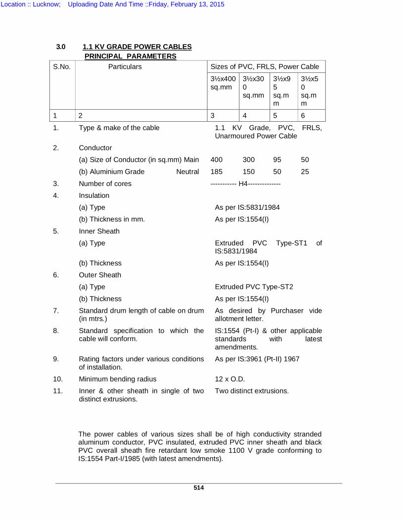
514
3.0 1.1 KV GRADE POWER CABLES
PRINCIPAL PARAMETERS S.No. Particulars Sizes of PVC, FRLS, Power Cable
3½x400 sq.mm
3½x300 sq.mm
3½x95 sq.mm
3½x50 sq.mm
1 2 3 4 5 6
1. Type & make of the cable 1.1 KV Grade, PVC, FRLS, Unarmoured Power Cable
2. Conductor (a) Size of Conductor (in sq.mm) Main 400 300 95 50
(b) Aluminium Grade Neutral 185 150 50 25
3. Number of cores ----------- H4-------------- 4. Insulation (a) Type As per IS:5831/1984 (b) Thickness in mm. As per IS:1554(I)
5. Inner Sheath (a) Type Extruded PVC Type-ST1 of
IS:5831/1984
(b) Thickness As per IS:1554(I) 6. Outer Sheath (a) Type Extruded PVC Type-ST2
(b) Thickness As per IS:1554(I) 7. Standard drum length of cable on drum
(in mtrs.) As desired by Purchaser vide allotment letter.
8. Standard specification to which the cable will conform.
IS:1554 (Pt-I) & other applicable standards with latest amendments.
9. Rating factors under various conditions of installation.
As per IS:3961 (Pt-II) 1967
10. Minimum bending radius 12 x O.D. 11. Inner & other sheath in single of two
distinct extrusions. Two distinct extrusions.
The power cables of various sizes shall be of high conductivity stranded aluminum conductor, PVC insulated, extruded PVC inner sheath and black PVC overall sheath fire retardant low smoke 1100 V grade conforming to IS:1554 Part-I/1985 (with latest amendments).
Location :: Lucknow; Uploading Date And Time ::Friday, February 13, 2015

515
3.1 CONDUCTOR The cable conductor shall be made from stranded aluminium to form
compact sector shaped conductor having resistance within the limits specified.
3.2 INSULATION Insulation of the cable shall be designed and manufactured for the specified
system voltage. The manufacturing process shall ensure that insulation shall be free from voids. The insulation shall withstand mechanical and thermal stresses under steady state and transient operating conditions. The insulation of the cables shall be in conformity with IS:5831-1984.
3.3 INNER SHEATH The inner sheath shall be of extruded PVC Type ST-1 as per IS:5831-1984.
The sheath shall be suitable to withstand the site conditions and the desired temperature. It shall be of adequate thickness and applied by the continuous process to produce a sheath of consistent quality and free from all defects.
3.4 OUTER SHEATH Extruded PVC serving Type ST-2 of IS:5831/1984 shall be applied with
suitable additives to prevent attack by rodents and termites. All servings must be given anti-termite treatment. The outer sheathing must be fire retardant and low smoke type.
3.5 CONSTRUCTION 3.5.1 Cables shall have fillers of PVC to provide substantially circular cross section
before the inner sheath is applied. The fillers should be suitable for the operating temperature of the cable and compatible with the insulating material.
3.5.2 All materials used in the manufacture of cable shall be new, unused and of
finest quality. All materials should comply with the applicable provisions of the test mentioned in this specification, Indian Standard specification, Indian Electricity Rules, Indian Electricity Act and any other applicable statutory provisions, rules and regulations. The PVC material used in the manufactures of cable should be of reputed manufacturer. No recycling of the PVC is permissible. The Purchaser reserves the right to ask for the documentary proof of the purchase of the material to be used for the manufacture of the cables and to check that the manufacture is complying with quality control as per this specification.
3.5.3 Workmanship shall be neat, clean and of highest grade. 3.6 CURRENT RATINGS 3.6.1 Rating factors of the cables under normal conditions of installation as per
IS:3961 Part-II-1967 and subsequent amendments thereof should be mentioned. The rating factors for different conditions of laying installations should be furnished. The 1 sec. and 3 se. short circuit current rating should also be furnished.
Location :: Lucknow; Uploading Date And Time ::Friday, February 13, 2015
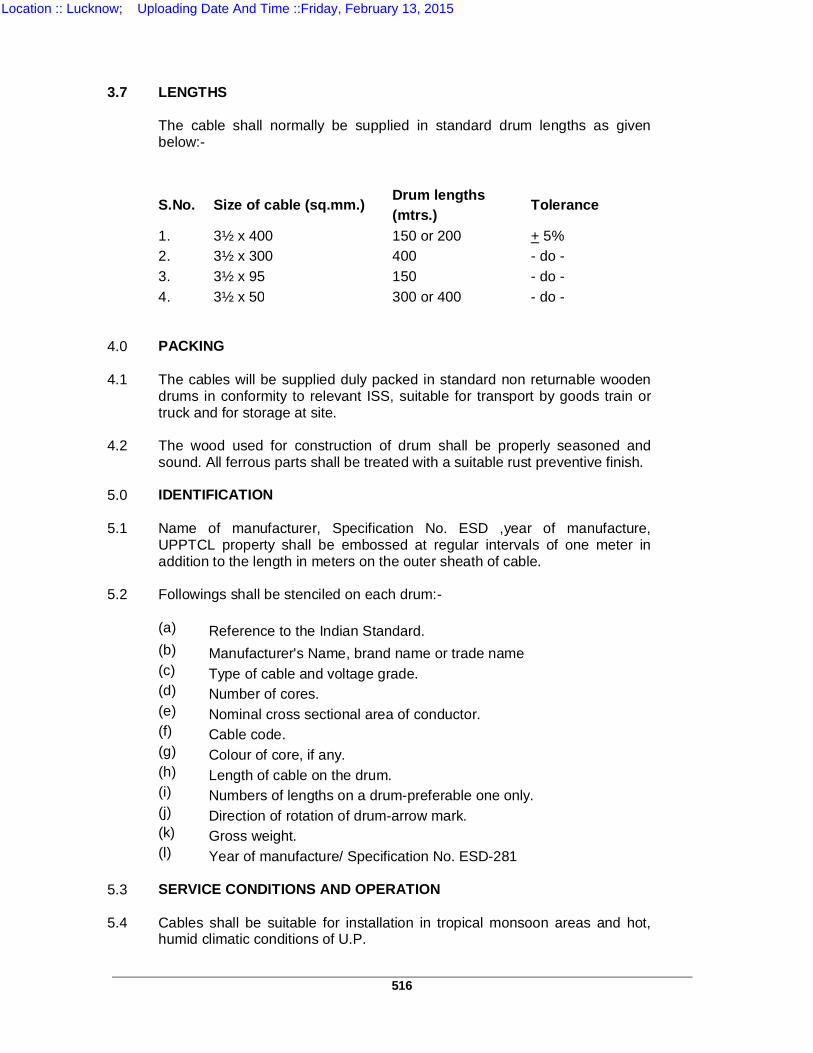
516
3.7 LENGTHS The cable shall normally be supplied in standard drum lengths as given
below:- S.No. Size of cable (sq.mm.) Drum lengths
(mtrs.) Tolerance
1. 3½ x 400 150 or 200 + 5% 2. 3½ x 300 400 - do - 3. 3½ x 95 150 - do - 4. 3½ x 50 300 or 400 - do - 4.0 PACKING 4.1
The cables will be supplied duly packed in standard non returnable wooden drums in conformity to relevant ISS, suitable for transport by goods train or truck and for storage at site.
4.2 The wood used for construction of drum shall be properly seasoned and
sound. All ferrous parts shall be treated with a suitable rust preventive finish. 5.0 IDENTIFICATION 5.1 Name of manufacturer, Specification No. ESD ,year of manufacture,
UPPTCL property shall be embossed at regular intervals of one meter in addition to the length in meters on the outer sheath of cable.
5.2 Followings shall be stenciled on each drum:- (a) Reference to the Indian Standard. (b) Manufacturer's Name, brand name or trade name (c) Type of cable and voltage grade. (d) Number of cores. (e) Nominal cross sectional area of conductor. (f) Cable code. (g) Colour of core, if any. (h) Length of cable on the drum. (i) Numbers of lengths on a drum-preferable one only. (j) Direction of rotation of drum-arrow mark. (k) Gross weight. (l) Year of manufacture/ Specification No. ESD-281 5.3 SERVICE CONDITIONS AND OPERATION 5.4
Cables shall be suitable for installation in tropical monsoon areas and hot, humid climatic conditions of U.P.
Location :: Lucknow; Uploading Date And Time ::Friday, February 13, 2015
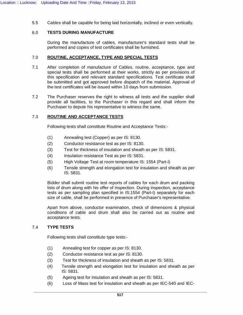
517
5.5 Cables shall be capable for being laid horizontally, inclined or even vertically. 6.0 TESTS DURING MANUFACTURE During the manufacture of cables, manufacturer's standard tests shall be
performed and copies of test certificates shall be furnished. 7.0 ROUTINE, ACCEPTANCE, TYPE AND SPECIAL TESTS 7.1
After completion of manufacture of Cables, routine, acceptance, type and special tests shall be performed at their works, strictly as per provisions of this specification and relevant standard specifications. Test certificate shall be submitted and got approved before dispatch of the material. Approval of the test certificates will be issued within 10 days from submission.
7.2
The Purchaser reserves the right to witness all tests and the supplier shall provide all facilities, to the Purchaser in this regard and shall inform the Purchaser to depute his representative to witness the same.
7.3 ROUTINE AND ACCEPTANCE TESTS Following tests shall constitute Routine and Acceptance Tests:- (1) Annealing test (Copper) as per IS: 8130. (2) Conductor resistance test as per IS: 8130. (3) Test for thickness of insulation and sheath as per IS: 5831. (4) Insulation resistance Test as per IS: 5831. (5) High Voltage Test at room temperature IS: 1554 (Part-I) (6) Tensile strength and elongation test for insulation and sheath as per
IS: 5831. Bidder shall submit routine test reports of cables for each drum and packing
lists of drum along with his offer of inspection. During inspection, acceptance tests as per sampling plan specified in IS:1554 (Part-I) separately for each size of cable, shall be performed in presence of Purchaser's representative.
Apart from above, conductor examination, check of dimensions & physical
conditions of cable and drum shall also be carried out as routine and acceptance tests.
7.4 TYPE TESTS Following tests shall constitute type tests:- (1) Annealing test for copper as per IS: 8130. (2) Conductor resistance test as per IS: 8130. (3) Test for thickness of insulation and sheath as per IS: 5831. (4) Tensile strength and elongation test for insulation and sheath as per
IS: 5831. (5) Ageing test for insulation and sheath as per IS: 5831. (6) Loss of Mass test for insulation and sheath as per IEC-540 and IEC-
Location :: Lucknow; Uploading Date And Time ::Friday, February 13, 2015
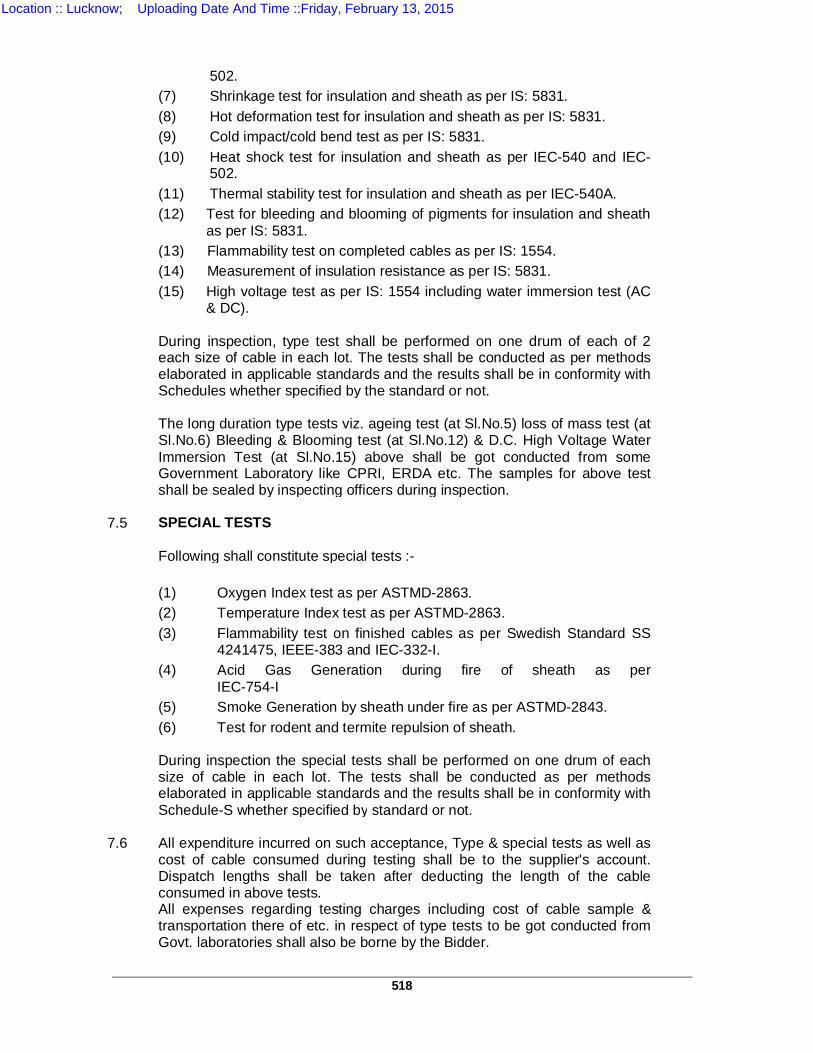
518
502.
(7) Shrinkage test for insulation and sheath as per IS: 5831. (8) Hot deformation test for insulation and sheath as per IS: 5831. (9) Cold impact/cold bend test as per IS: 5831. (10) Heat shock test for insulation and sheath as per IEC-540 and IEC-
502. (11) Thermal stability test for insulation and sheath as per IEC-540A. (12) Test for bleeding and blooming of pigments for insulation and sheath
as per IS: 5831. (13) Flammability test on completed cables as per IS: 1554. (14) Measurement of insulation resistance as per IS: 5831. (15) High voltage test as per IS: 1554 including water immersion test (AC
& DC). During inspection, type test shall be performed on one drum of each of 2
each size of cable in each lot. The tests shall be conducted as per methods elaborated in applicable standards and the results shall be in conformity with Schedules whether specified by the standard or not.
The long duration type tests viz. ageing test (at Sl.No.5) loss of mass test (at
Sl.No.6) Bleeding & Blooming test (at Sl.No.12) & D.C. High Voltage Water Immersion Test (at Sl.No.15) above shall be got conducted from some Government Laboratory like CPRI, ERDA etc. The samples for above test shall be sealed by inspecting officers during inspection.
7.5 SPECIAL TESTS Following shall constitute special tests :- (1) Oxygen Index test as per ASTMD-2863. (2) Temperature Index test as per ASTMD-2863. (3) Flammability test on finished cables as per Swedish Standard SS
4241475, IEEE-383 and IEC-332-I. (4) Acid Gas Generation during fire of sheath as per
IEC-754-I (5) Smoke Generation by sheath under fire as per ASTMD-2843. (6) Test for rodent and termite repulsion of sheath. During inspection the special tests shall be performed on one drum of each
size of cable in each lot. The tests shall be conducted as per methods elaborated in applicable standards and the results shall be in conformity with Schedule-S whether specified by standard or not.
7.6
All expenditure incurred on such acceptance, Type & special tests as well as cost of cable consumed during testing shall be to the supplier's account. Dispatch lengths shall be taken after deducting the length of the cable consumed in above tests.
All expenses regarding testing charges including cost of cable sample & transportation there of etc. in respect of type tests to be got conducted from Govt. laboratories shall also be borne by the Bidder.
Location :: Lucknow; Uploading Date And Time ::Friday, February 13, 2015
519
7.7
The Purchaser reserves the right to modify/ delete or add any test. The Bidders shall confirm that all test equipments and testing facilities are available at their works for carrying out all above tests by them. The compliance to the above test clause is pre qualifying condition for this Bid and the bidder shall confirm to carryout the specified tests.
Location :: Lucknow; Uploading Date And Time ::Friday, February 13, 2015
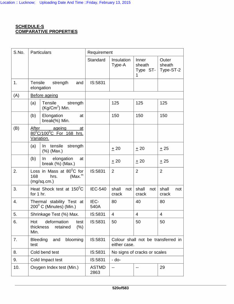
520of583
SCHEDULE-S COMPARATIVE PROPERTIES
S.No. Particulars Requirement
Standard Insulation Type-A
Inner sheath Type ST-1
Outer sheath Type-ST-2
1. Tensile strength and elongation
IS:5831
(A) Before ageing
(a) Tensile strength (Kg/Cm2) Min.
125 125 125
(b) Elongation at break(%) Min.
150 150 150
(B) After ageing at 800C/1000C For 168 hrs. Variation.
(a) In tensile strength (%) (Max.) + 20 + 20 + 25
(b) In elongation at break (%) (Max.)
+ 20 + 20 + 25
2. Loss in Mass at 800C for 168 hrs. (Max.m (mg/sq.cm.)
IS:5831 2 2 2
3. Heat Shock test at 1500C for 1 hr.
IEC-540 shall not crack
shall not crack
shall not crack
4. Thermal stability Test at 2000 C (Minutes) (Min.)
IEC-540A
80 40 80
5. Shrinkage Test (%) Max. IS:5831 4 4 4
6. Hot deformation test thickness retained (%) Min.
IS:5831 50 50 50
7. Bleeding and blooming test
IS:5831 Colour shall not be transferred in either case.
8. Cold bend test IS:5831 No signs of cracks or scales
9. Cold Impact test IS:5831 - do-
10. Oxygen Index test (Min.) ASTMD 2863
-- -- 29
Location :: Lucknow; Uploading Date And Time ::Friday, February 13, 2015
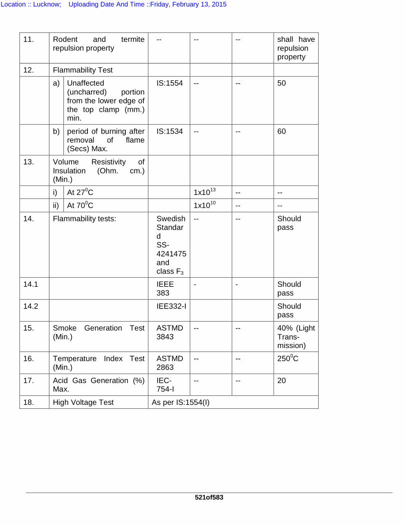
521of583
11. Rodent and termite
repulsion property -- -- -- shall have
repulsion property
12. Flammability Test
a) Unaffected (uncharred) portion from the lower edge of the top clamp (mm.) min.
IS:1554 -- -- 50
b) period of burning after removal of flame (Secs) Max.
IS:1534 -- -- 60
13. Volume Resistivity of Insulation (Ohm. cm.) (Min.)
i) At 270C 1x10¹³ -- --
ii) At 700C 1x10¹⁰ -- --
14. Flammability tests:
Swedish Standard SS-4241475 and class F3
-- -- Should pass
14.1 IEEE 383
- - Should pass
14.2 IEE332-I Should pass
15. Smoke Generation Test (Min.)
ASTMD 3843
-- -- 40% (Light Trans-mission)
16. Temperature Index Test (Min.)
ASTMD 2863
-- -- 2500C
17. Acid Gas Generation (%) Max.
IEC-754-I
-- -- 20
18. High Voltage Test As per IS:1554(I)
Location :: Lucknow; Uploading Date And Time ::Friday, February 13, 2015
522of583
TS-13 TECHNICAL SPECIFICATION FOR11 KV HT XLPE CABLE 1.0 SCOPE:
The specification covers design, engineering, manufacture, stage testing, inspection and testing before supply, delivery at site, laying & jointing of 11 KV XLPE cables for use with effectively earthed distribution system.
2.0 STANDARDS: 2.1 The materials shall conform in all respects to the relevant Indian Standards Specification with latest
amendments thereto.
Indian Standard No. Title Internationally Recognized Standard
IS-7098 Part-II/1985 Specification for Cross Linked Polyethylene Insulated PVC Sheathed Cables for working Voltages from 33 KV up to and including 33 KV
IS-5831/1984 PVC insulation and sheath of Electric cables
IEC 502 (1983)
IS-8130/1984 Conductors for insulated electric Cables and Flexible cords
IEC 228 (1978)
IS-10418/1982 Specification for cable drum 3.0 TECHNICAL REQUIREMENTS: 1.1 MAIN FEATURES:
The Power Cable shall be 11 KV grade, high conductivity, stranded compacted circular Aluminium Conductor, XLPE insulated, extruded inner PVC sheathed, galvanized steel strip armoured with overall separate extruded PVC outer sheathed, conforming to relevant standards suitable for 11 KV three phase 50 cycle second earthed system.
1.2 MATERIALS AND CONSTRUCTION: 3.2.1 CONDUCTOR:
The cable conductor shall be made from stranded aluminium to form compacted circular conductor having resistance within the specified limits as per relevant standards.
3.2.2 CONDUCTOR SHIELD:
The conductor shall have a non-magnetic semi-conducting screen, which will ensure perfectly smooth profile and avoid concentration. The Conductor screen shall be extruded in the same operation, as the insulation.
Location :: Lucknow; Uploading Date And Time ::Friday, February 13, 2015
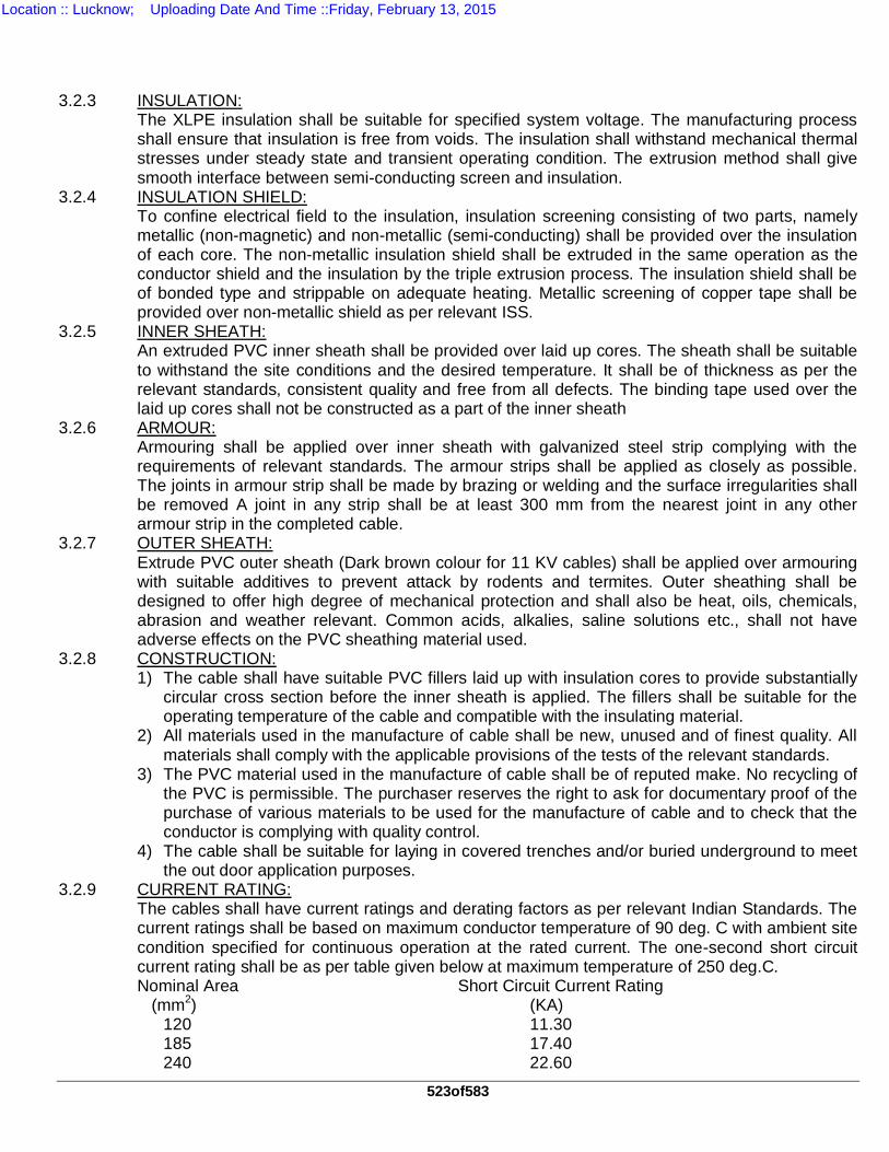
523of583
3.2.3 INSULATION: The XLPE insulation shall be suitable for specified system voltage. The manufacturing process shall ensure that insulation is free from voids. The insulation shall withstand mechanical thermal stresses under steady state and transient operating condition. The extrusion method shall give smooth interface between semi-conducting screen and insulation.
3.2.4 INSULATION SHIELD: To confine electrical field to the insulation, insulation screening consisting of two parts, namely metallic (non-magnetic) and non-metallic (semi-conducting) shall be provided over the insulation of each core. The non-metallic insulation shield shall be extruded in the same operation as the conductor shield and the insulation by the triple extrusion process. The insulation shield shall be of bonded type and strippable on adequate heating. Metallic screening of copper tape shall be provided over non-metallic shield as per relevant ISS.
3.2.5 INNER SHEATH: An extruded PVC inner sheath shall be provided over laid up cores. The sheath shall be suitable to withstand the site conditions and the desired temperature. It shall be of thickness as per the relevant standards, consistent quality and free from all defects. The binding tape used over the laid up cores shall not be constructed as a part of the inner sheath
3.2.6 ARMOUR: Armouring shall be applied over inner sheath with galvanized steel strip complying with the requirements of relevant standards. The armour strips shall be applied as closely as possible. The joints in armour strip shall be made by brazing or welding and the surface irregularities shall be removed A joint in any strip shall be at least 300 mm from the nearest joint in any other armour strip in the completed cable.
3.2.7 OUTER SHEATH: Extrude PVC outer sheath (Dark brown colour for 11 KV cables) shall be applied over armouring with suitable additives to prevent attack by rodents and termites. Outer sheathing shall be designed to offer high degree of mechanical protection and shall also be heat, oils, chemicals, abrasion and weather relevant. Common acids, alkalies, saline solutions etc., shall not have adverse effects on the PVC sheathing material used.
3.2.8 CONSTRUCTION: 1) The cable shall have suitable PVC fillers laid up with insulation cores to provide substantially
circular cross section before the inner sheath is applied. The fillers shall be suitable for the operating temperature of the cable and compatible with the insulating material.
2) All materials used in the manufacture of cable shall be new, unused and of finest quality. All materials shall comply with the applicable provisions of the tests of the relevant standards.
3) The PVC material used in the manufacture of cable shall be of reputed make. No recycling of the PVC is permissible. The purchaser reserves the right to ask for documentary proof of the purchase of various materials to be used for the manufacture of cable and to check that the conductor is complying with quality control.
4) The cable shall be suitable for laying in covered trenches and/or buried underground to meet the out door application purposes.
3.2.9 CURRENT RATING: The cables shall have current ratings and derating factors as per relevant Indian Standards. The current ratings shall be based on maximum conductor temperature of 90 deg. C with ambient site condition specified for continuous operation at the rated current. The one-second short circuit current rating shall be as per table given below at maximum temperature of 250 deg.C. Nominal Area Short Circuit Current Rating (mm2) (KA)
120 11.30 185 17.40 240 22.60
Location :: Lucknow; Uploading Date And Time ::Friday, February 13, 2015
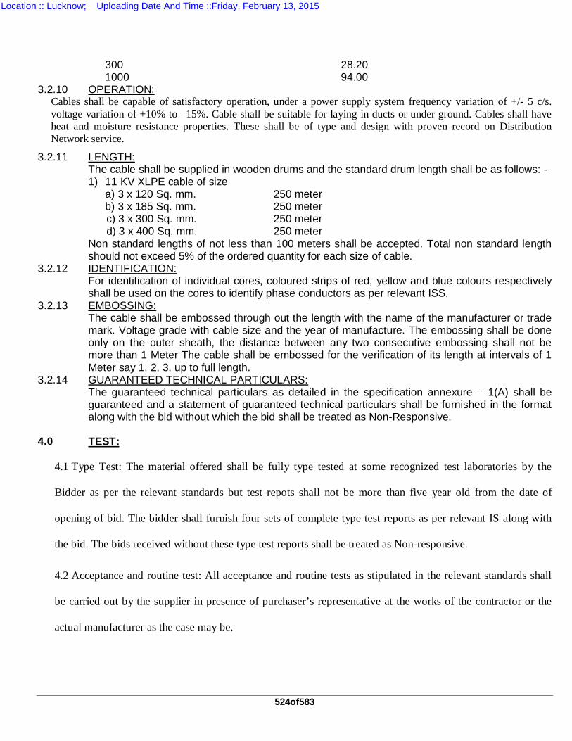
524of583
300 28.20 1000 94.00
3.2.10 OPERATION: Cables shall be capable of satisfactory operation, under a power supply system frequency variation of +/- 5 c/s. voltage variation of +10% to –15%. Cable shall be suitable for laying in ducts or under ground. Cables shall have heat and moisture resistance properties. These shall be of type and design with proven record on Distribution Network service.
3.2.11 LENGTH: The cable shall be supplied in wooden drums and the standard drum length shall be as follows: - 1) 11 KV XLPE cable of size a) 3 x 120 Sq. mm. 250 meter b) 3 x 185 Sq. mm. 250 meter c) 3 x 300 Sq. mm. 250 meter d) 3 x 400 Sq. mm. 250 meter Non standard lengths of not less than 100 meters shall be accepted. Total non standard length should not exceed 5% of the ordered quantity for each size of cable.
3.2.12 IDENTIFICATION: For identification of individual cores, coloured strips of red, yellow and blue colours respectively shall be used on the cores to identify phase conductors as per relevant ISS.
3.2.13 EMBOSSING: The cable shall be embossed through out the length with the name of the manufacturer or trade mark. Voltage grade with cable size and the year of manufacture. The embossing shall be done only on the outer sheath, the distance between any two consecutive embossing shall not be more than 1 Meter The cable shall be embossed for the verification of its length at intervals of 1 Meter say 1, 2, 3, up to full length.
3.2.14 GUARANTEED TECHNICAL PARTICULARS: The guaranteed technical particulars as detailed in the specification annexure – 1(A) shall be guaranteed and a statement of guaranteed technical particulars shall be furnished in the format along with the bid without which the bid shall be treated as Non-Responsive.
4.0 TEST:
4.1 Type Test: The material offered shall be fully type tested at some recognized test laboratories by the
Bidder as per the relevant standards but test repots shall not be more than five year old from the date of
opening of bid. The bidder shall furnish four sets of complete type test reports as per relevant IS along with
the bid. The bids received without these type test reports shall be treated as Non-responsive.
4.2 Acceptance and routine test: All acceptance and routine tests as stipulated in the relevant standards shall
be carried out by the supplier in presence of purchaser’s representative at the works of the contractor or the
actual manufacturer as the case may be.
Location :: Lucknow; Uploading Date And Time ::Friday, February 13, 2015

525of583
5.0 QUALITY ASSURANCE PLAN: 5.1 The successful bidder shall within 30 days of placement of order, submit following information to
the purchaser. i. List of raw materials as well as bought out accessories and the names of sub-suppliers
selected from those furnished along with officers. ii. Type test certificates of the raw materials and bought out accessories, if required by the
purchaser. iii. Quality assurance plan (QAP) with hold points for purchaser’s inspection. The quality
assurance plan and purchasers hold points shall be discussed between the purchaser and bidder before the QAP is finalized.
6.0 PACKING & FORWARDING:
6.1 The equipment shall be packed in drum suitable for vertical / horizontal transport as the case may be and
suitable to withstand handling during transport and outdoor storage during transit. The supplier shall be
responsible for any damage to the equipment during transit, due to improper and inadequate packing. The
easily damageable material shall be carefully packed and marked with the appropriate caution symbol.
Wherever necessary, proper arrangement for lifting such as lifting hooks etc. shall be provided. Any material
found short inside the packing shall be supplied immediately by supplier without any extra cost.
6.2 Each consignment shall be accompanied with a detailed packing list containing the following information:
a. Name of the consignment b. Details of consignment c. Destination d. Total weight of consignment e. Handling and packing instruction. f. Bill of material and contents of each package. 6.3 The supplier shall ensure that the packing list and bill of material are approved by the purchaser
before dispatch. 6.4 The packing shall be done as per the manufacturer’s standard practice. However, he should
ensure the packing is such that the material should not get damaged during transit by Rail/Road. 6.5 The marking on each package shall be as per the relevant standards and shall also contain
“APDRP/DVVNL”. 6.6 Cable shall be supplied on non-returnable wooden drums as per relevant standards and shall be
suitable for any mode of transport and for storage at site. Wood used for drums shall be seasoned and wood preservative shall be applied to entire drum. All ferrous parts shall have anti rusting coating. Each drum shall be marked on it with following information by indelible ink. (a) Specification No. (b) Consignee and Destination Station (c) Name of manufacturer and trademark. (d) Size of cable (No. of cores/area of conductor of one core) (e) Type of cable and rated voltage (f) Gross weight of drum (Approx.) (g) Length of cable in the drum with individual length if more than one.
Location :: Lucknow; Uploading Date And Time ::Friday, February 13, 2015
526of583
(h) Net weight of cable. (i) ISI/ISO certification mark, if available.
6.7 A layer of waterproof paper shall be applied to the surface of the drum and outer layer of cable. 6.8 Clear space of 40 mm shall be left between the cable and the lagging. 6.9 Packing shall be robust enough for rough handling during transportation. 6.10 The ends of all the cables, should be capped & suitably scaled by means of non-hygroscopic
material.
Location :: Lucknow; Uploading Date And Time ::Friday, February 13, 2015
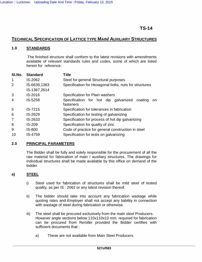
527of583
TS-14 TECHNICAL SPECIFICATION OF LATTICE TYPE MAIN/ AUXILIARY STRUCTURES 1.0 STANDARDS The finished structure shall conform to the latest revisions with amendments
available of relevant standards rules and codes, some of which are listed herein for reference.
Sl.No. Standard Title 1 IS-2062 Steel for general Structural purposes 2 IS-6639,1363 Specification for Hexagonal bolts, nuts for structures IS-1367,2614 3 IS-2016 Specification for Plain washers 4 IS-5258 Specification for hot dip galvanized coating on
fasteners 5 IS-7215 Specification for tolerances in fabrication 6 IS-2629 Specification for testing of galvanizing 7 IS-2633 Specification for process of hot dip galvanizing 8 IS-209 Specification for quality of zinc 9 IS-800 Code of practice for general construction in steel 10 IS-4759 Specification for tests on galvanizing 2.0 PRINCIPAL PARAMETERS The Bidder shall be fully and solely responsible for the procurement of all the
raw material for fabrication of main / auxiliary structures. The drawings for individual structures shall be made available by this office on demand of the bidder.
a) STEEL i)
Steel used for fabrication of structures shall be mild steel of tested quality, as per IS : 2062 or any latest revision thereof.
ii)
The bidder should take into account any fabrication wastage while quoting rates and Employer shall not accept any liability in connection with wastage of steel during fabrication or otherwise.
iii)
The steel shall be procured exclusively from the main steel Producers. However angle sections below 110x110x10 mm. required for fabrication can be procured from Reroller provided the Bidder certifies with sufficient documents that :
a) These are not available from Main Steel Producers.
Location :: Lucknow; Uploading Date And Time ::Friday, February 13, 2015
528of583
b)
Rerolling of structural steel sections is done from billets of tested quality.
c) Rerolled sections are duly tested as per IS: 2062. iv)
If a particular section is not available in the market then Bidder shall use next available higher section with specific approval of the employer, and, additional cost on account of using higher section shall not be payable to the Bidder.
b) ZINC i)
Zinc of purity not less than 99.95% shall be used, Zinc shall conform to IS 209/1979 or its latest revisions.
ii)
All wastage, excess consumption, during galvanising or otherwise of zinc, shall be to Bidder's account.
c) BOLTS, NUTS & WASHERS Galvanized bolts & nuts required shall be of GKW make. Bolts and Nuts shall
be duly galvanised as per IS: 1367 Part XIII/1983. Bolts shall conform to IS 6639-1972 and nuts to IS 1363 with their latest amendment. The mechanical properties shall conform to Clause 4.6 for bolts and Clause 4 for nuts of IS: 1367-1972. Testing of bolts & nuts shall be as per above referred IS and IS: 2614. Flat washers shall be 5 mm. thick or as required and shall be made of mild steel and duly galvanised.
Spring washers shall be suitable for 16mm. size bolts, 3.5 mm. thick non
square section as per IS: 3063/-1972. These shall be galvanised as per IS: 1573.
The quantity of various sizes of bolts, nuts and washers are indicated in
relevant drawings of the employer. 3.0 DRAWING AND DATA The substation structures proposed to be procured against this specification,
shall be as per the designs of the employer. Outline structural drawings of each structure shall be made available by the employer to the successful bidder for developing detailed shop drawings and actual bill of material. Two copies of such shop drawings prepared by the Bidder shall be made available to the Employer. The Bidder shall be fully responsible for checking the drawings made available by the Employer and developing the shop drawing correctly. However 3 copies of detailed bills of materials will be submitted by the Bidder to employer for Approval. Typical drawings (Typical for guidance) are enclosed at annexes.
4.0 FABRICATION Based on the drawings of the employer and his own detailed shop drawings
the Bidder shall prepare the model assembly of each structure within one
Location :: Lucknow; Uploading Date And Time ::Friday, February 13, 2015
529of583
month and send a call for inspection of the model assembly and also to verify the bill of material.
The Engineer shall check in detail such model assemblies and verify the bills
of material of each. Any modification, rectification, corrections required in the structures to make it conform to the approved drawings and requirements to this specification or standards, shall be made by the Bidder and get approved from the Engineer, Any approval of the model assemblies shall not relieve the Bidder in any way of his responsibility to supply correctly fabricated / galvanised structure in conformity with approved designs, Standards Specification.
After approval of each model assembly, the mass fabrication of the structures
shall be started by the Bidder as soon as employer’s approval is received by him and complete as per the approved delivery schedule. During mass fabrication, the Bidder shall ensure that complete structures of different types are made available to the employer @ 150 MT Per month, and, the fabrication shall be so programmed so as to make this possible on a regular basis . Mass fabrication of one type of structure may be required to be done at more than one time, depending upon the site requirement of the employer.
Following points relevant to the fabrication work shall be complied by the
Bidder. The employer, however, reserves the right at all times to inspect the fabrication of structures at Bidder's or his sub - Bidder's works.
b) All parts of the structures shall be fabricated in accordance with the
drawings approved by the employer and detailed shop drawings prepared by the Bidder. Main structures shall have bolted connections, except connection of the bottom base plate with the leg members as per the approved drawings. No other welding shall be permitted at any point, unless, otherwise previously approved by the employer for main structures. For auxiliary structures angle or channel boxes may be required by welding as per the drawings of the employer.
c) Fabrication of structures shall be carried out in conformity with the
latest practice employed in the manufacture of similar structures, using power driven cropping, punching, shearing and drilling machines. The extent of various operations shall be governed by relevant Indian or any other approved standard specification, and the standard practices followed for such operations.
d) No rough edge shall be permitted any where in the entire structure.
The flanges of the angle sections at the ends of members shall be properly chamfered.
e) Full interchangeability shall be guaranteed. f) No welding, filling or plugging shall be permitted unless previously
approved. Welding of two or more pieces to obtain length of a member will not be permitted.
Location :: Lucknow; Uploading Date And Time ::Friday, February 13, 2015
530of583
g) All sections, plates and bars, before any work is done on them, shall
be straightened, made free from twists, carefully levelled and made true to detailed drawings by methods, which will not injure the materials, so that when assembled, the adjacent surfaces are in close contact throughout. Hammering will not be permitted for straightening or flattening of members.
h) Cutting of members shall be effected by cropping, flame cutting or
sawing. Members over 10mm thickness shall be sawn or flame cut followed by grinding. The surface so cut shall be clean, smooth, reasonable square and free from any distortion.
i) Holes in the members shall be either punched or drilled with the help
of jigs and fixtures. Drilled holes will be preferred. However, members up to 12 mm thickness may be punched. Members over 12 mm thickness shall be drilled. All burrs left after drilling or punching shall be removed completely. Holes adjacent to the bends shall to drilled or punched after bending.
j) Holes for bolts shall be circular or oval, lobbed forms of holes shall not
be permitted. The diameter of hole shall be 1.5 mm more than the diameter of bolts.
k) The holes shall be perpendicular to the plates or angles. l) The accuracy of location of holes shall be such that for any group
when assembled, it shall admit the bolt at right angles to the planes of connection.
m) Members shall be bent hot, in case of small bends , cold bending
may be done with the prior approval of the Engineer, provided no fracture of material occurs. All the bending operations shall be done by pressure. No bending of members shall be done for slope above 45 degree.
n) When members are spliced by a lap joint, heel of inside angle shall be
rounded to the minimum possible radius, consistent with proper fit with the fillet of the outside angle. The thickness of the ground heel shall not be less than that of the leg. Flat heeling will not be allowed. Detail of joints is available in structure drawings.
o) Tolerances- I) The maximum allowable difference in diameter of the hole on
the two sides of plate or angles shall not exceed 0.8mm . II) The tolerance cumulative and between consecutive holes shall
be within ± 0.5 mm. III) The tolerance on the overall length of member shall be within
±1.6 mm.
Location :: Lucknow; Uploading Date And Time ::Friday, February 13, 2015
531of583
IV) The tolerance on back mark shall be within ±0.5mm. o) The minimum spacing from center to center of bolt holes should be as
shown below: - As per IS 802 ( Part II ) Size of Bolts Minimum Spacing 12 mm 32 16 mm 40 20 mm 48 p) The minimum distance from center to center of any hole to any edge
should be as shown below:- Bolt dia
(mm) Hole dia (mm)
Rolled Edge Distance (mm)
Sheared Edge Distance (mm)
12 13.5 16 20 16 17.5 20 23 20 21.5 25 28 Holes shall be perfectly circular. 5.0 WELDING a) Welding is to be resorted to only where indicated in the structural
drawings. b) Surface to be welded shall be made absolutely free from grease, paint
& loose scales etc. The joints shall be prepared in accordance with the approved fabrication drawings.
c) All welds shall be free from defects like blow holes, slag inclusions,
lack of penetration etc. Welds shall show uniform sections, and, .weld size need not exceed thickness of thinner part joined.
All fillet welds shall be inspected for flaws by the following methods. i) Radio graphic inspection, ii) Magnetic particle examination as per ASTM E125-63. 6.0 CONNECTIONS a) For main structures: All the connections are bolted type, the details of which will be available in
structure drawings supplied to the Bidder for developing detailed shop drawing and bills of materials except for bottom of members with the base plate which may be welded as per drawing.
Location :: Lucknow; Uploading Date And Time ::Friday, February 13, 2015
532of583
b) For auxiliary structures: The joints etc. shall be specified in each drawing separately however they
are either bolted or welded connections. 7.0 MARKINGS All pieces covered under supply of the structures shall have distinct erection
marks as given on the drawings and approved bills of materials, made with a steel punch and sufficiently indented with letters and figures, not less than 12mm x 18mm. in sizes, so that these are clearly visible after galvanising. The letters shall indicate the type of structure (ATM, BTM, CTM or other) for which the member is meant and numeral shall indicate the member mark as per drawing and approved bills of materials. These erection marks shall be stamped near one end, and, in the same relative position on each piece, in such a way that the mechanical properties of members are not affected. Special care must be taken to stamp the correct erection mark. The Bidder shall be entirely responsible for any disruption of work, or delay in completion of work of delay in payment of Bidder's bills on account of wrong erection marks.
8.0 GALVANISING i) All members of the structures and special structures along with its
cleats, bolts, nuts & washers, fixing attachments, if any, shall be hot dip galvanised.,
ii) The galvanizing shall be done after all fabrication work is completed on
the members. Galvanising on fabrication member shall be done by hot dip process in full compliance with the latest revision of IS : 2629. Galavanising of bolts & nuts shall be in accordance with IS: 1367 Part XIII/63 and that for spring washers in accordance with IS: 1573. Material to be galvanized is to be kept free from grease and paint etc., during and after fabrication. After galvanising, the surface shall be free from all sharp edge and metal nodules and there shall be no clogging of bolt holes due to stay of zinc. The bidders shall submit with their bids, the process of galvanizing adopted by them, along with the devices and facilities available with them. For more authoritative and better control on quality of galvanizing, they shall also state the minimum and maximum percentage increase in the weight of the completely galvanized materials compared to their black weight and the quantity of zinc required per metric ton of the black steel weight of the fabrication structures.
iii) Tests on the galvanised samples of fabricated material shall be carried
out regularly in strict accordance with the IS - 4759. If the galvanizing does not satisfy testing requirements, entire batch represented by the sample piece shall be rejected and regalvanised to satisfy the test requirement without any extra expenditure to the employer's account.
Location :: Lucknow; Uploading Date And Time ::Friday, February 13, 2015
533of583
iv) In addition, strict inspection of the galvanised material shall be carried
out by the Bidder before dispatch and any visible or suspected defect shall be rectified forthwith.
9.0 TESTS All materials offered shall be fully tested by the bidder as per the relevant
standards. All acceptance and routine tests as stipulated in the relevant standards shall
be carried out by the supplier in the presence of employer’s representative. 10.0 INSPECTION In addition to the provisions in clause no. 2.4.0 of General conditions, the
following shall also apply:- a) Should any member of the structure be found not to comply with the
approved designs/ drawings or with the provisions of the specifications, it shall be liable to rejection. No member, once rejected shall be resubmitted for inspection, except in cases where the employer or his authorized representative considers the defect as rectifiable.
b) Defects which may appear during fabrication shall be made good with
the consent of, and, according to the procedure laid down by the employer.
c) All gauges and templates necessary to satisfy the employer shall be
supplied by the manufacturer. d) The correct grade and quality of steel and zinc shall be used by the
manufacturer. To ascertain the quality of steel / zinc used, the inspector may at his discretion, get the material tested at an approved laboratory.
e) The Bidder will offer his material for inspection in following two
stages. 1. Model assembly inspection 2. Fully fabricated galvanized material inspection. f) The employer representative shall inspect the Model assemblies
offered for inspection and on being satisfied give clearance to the Bidder, for mass fabrication, of the cleared structure.
g) The representative shall also carry out galvanized tests on the
randomly selected pieces of galvanized structures. On successful inspection, the Bidder will submit to the employer
Location :: Lucknow; Uploading Date And Time ::Friday, February 13, 2015
534of583
- manufacturer's test certificates
- inspection report etc.
and will request for issue of dispatch clearance from the employer. 11.0 PACKAGING & FORWARDING i) Light angle sections shall be wire bundled and heavy angle sections
may be sent loose. ii) Cleat angles, plates, hangers, ‘U’ bolts, pack washers and similar
loose pieces shall be nested and bolted together in multiples or securely wired together through holes.
iii) Bolts, nuts washers and other attachments shall be packed in non
returnable double gunny bags and accurately tagged in accordance with contents.
iv) The packing shall be made in such a way as to avoid losses /
damages during transit, each bundle or package shall be appropriately marked. Any loss or damage during transit shall be made up/rectified by the Bidder at no extra cost to the employer.
v) No extra charges for packing shall be admissible. Bidders may include
its cost in their quoted rates. 12.0 MODE OF CALCULATION OF WEIGHT The weight of structure ordered against this specification mentioned in
“quantity” clause is black weight of the structure which is defined as below:- Black weight of the structure is the weight without galvanising and without
deduction for holes, notches, bevel cuts etc. for irregular shapes the minimum size of the rectangle covering the irregular shape will be taken for weight calculations. Bill of materials for each structure shall indicate this black weight.
13.0 PRICE i)
The rates quoted in the schedule shall be applicable on black weight of structure and are inclusive of cost of zinc and other raw materials, fabrication, galvanising, packing, forwarding, unloading & stacking at site (including transit up to site) including cost of MS angles, channels , plates, welding, flat washers, spring washers fasteners, step bolts, U bolts etc. The price shall include supply of 2.5 % extra bolts, nuts & washers in nos. for each individual structure to cater for wastage during erection of structures. The Bidder shall transport the fabricated steel structure through rail / road or by any means of transport and shall be fully responsible for any shortage or loss during transit. Rate should also include transit insurance. Any shortage / damage shall be made up/rectified by the Bidder with in one month time without any extra cost to the employer.
Location :: Lucknow; Uploading Date And Time ::Friday, February 13, 2015
535of583
INFORMATION ON ESSENTIAL FACILITIES AVAILABLE WITH THE FABRICATOR ( To be filled in by the bidder ) Straightening: Is there any facility for Straightening of section i.e. Angles / Channels / Rounds etc? If yes , intimate the type of Machine. 1. Section Cutting: Is there any facility for section cutting? If yes intimate the type of machine;
also intimate the maximum of thickness of angle flanges and diameter of round, which can be cut by above machine. Capacity of machine may also be intimated.
2. Cropping: i) Indicate the facility for cropping of plates ii) Intimate the type of machine and the thickness and width it can be crop. 3. Punching / Drilling: i) Indicate the facilities for Punching and drilling of holes. ii) Thickness of plates/angles flanges that can be punched or drilled may
be intimated separately for punching and drilling machine respectively. 4. Welding / Gas cutting: Indicate the facilities available for performing this operation. Bidder should
clearly specify whether facility of radiographic inspection and magnetic particle Examination of welds are available.
5. Facilities for checking design of structures including availability of qualified
Personnel etc. B: GALVANIZING: Is there any facility for hot dip galvanizing of structures available at your
works? If yes then furnish the following information:
a) The galvanizing plant is coal fired or oil fired.
Location :: Lucknow; Uploading Date And Time ::Friday, February 13, 2015
536of583
b) The dimensions of the galvanizing tank to assess the maximum size of the
members that can be galvanized. c) Facilities for management and control of temperature of zinc during
galvanizing process. d) Test facilities available for thickness of the coating of zinc on members. e) Test facilities to check gm/ sq.m coating of zinc on members. f) Availability of various IS codes pertaining to galvanizing at the test laboratory. g) Minimum and maximum percentage increase in weight of galvanized structure
compares to their black weight. h) Quantity of zinc required per MT of black weight of steel structure.
Location :: Lucknow; Uploading Date And Time ::Friday, February 13, 2015
537of583
TS-15
TECHNICAL SPECIFICATION OF FOUNDATION ANCHOR BOLTS 1.0 STANDARDS : The finished foundation anchor bolts shall conform to the latest revisions with
amendments available of relevant standards rules and codes, some of which are listed herein for reference.
Sl.No Standard Title 1 IS-2062 Steel for general Structural purposes
2 IS-1608 Method of Tensile Testing
3 IS-5624 Specification for markings
4 IS-4218 Specification for Threading
5 IS-2614 Specification for sampling & acceptance
6 IS-2629 Specification for testing of galvanizing
7 IS-2633 Specification for process of hot dip galvanizing
8 IS-209 Specification for quality of zinc 2.0 PRINCIPAL PATRAMETERS 2.1
All the raw material required for fabrication and partial galvanizing of the anchor bolts shall be procured by the Bidder. The MS rounds and MS plates used for manufacturing the anchor bolts shall be free from all rust, pitting, greasing etc. They should conform to technical parameters for Grade A steel of IS-2062. M/S GKW make nuts, or equivalent quality approved by the employer, shall be supplied with anchor bolts. In case galvanized nuts are not available, the Bidder may purchase black nuts from M/S GKW and galvanize them as per relevant IS.
2.2 All the above anchor bolts shall be fitted and supplied with GKW make double
nuts duly galvanized. 3.0 DRAWING AND DATA The foundation anchor bolts proposed to be procured against this
specification shall be as per the design of the employer and shall be fabricated as per the drawing enclosed as per drawing no. W-04921/1.
4.0 FABRICATION 1. The anchor bolts shall be fabricated out of tested quality MS-Rounds
only, in accordance with the drawing provided with this specification. 2. The threads shall conform to the metric series IS-4218 Part I
corresponding to the nuts of size of M/S GKW make and shall be undercut by .0043 mm for galvanizing.
Location :: Lucknow; Uploading Date And Time ::Friday, February 13, 2015
538of583
3. The anchor bolts shall be supplied fitted with double nuts of M/S GKW
make, or equivalent approved quality, duly galvanized. The top portion of anchor bolts including threads shall be galvanized as indicated in the drawing.
4. All the anchor bolts shall be duly marked as per IS-5626. 5. Welding shall conform to relevant ISS for fillet welding. 5.0 GALVANIZING The anchor bolts as well as nuts shall be galvanized by hot dip process
conforming to latest revisions of IS-2629 and 2633. Minimum weight of coating of zinc during galvanizing shall be 305 gms. per sq.m. for threaded portion and 610 gms. per sq.m. for the other surfaces. The galvanized external threads shall not be recut. The zinc used shall be not less than 99.5% pure conforming to IS-209 and shall be free from sulfur, carbon or silica. The galvanizing shall be done at correct temperatures and shall provide for substantial diffusion of Hydrogen, maintaining the molten zinc bath free from impurities. The nuts and bolts shall be meticulously cleaned before galvanizing. The galvanized surfaces shall be free from defects like strain, dross , excessive projections or other imperfections, metals etc. which would impair serviceability ,quality, strength or finish of the anchor bolts. There should not be any clogging of threads due to staying of zinc on them during galvanizing. The threads must fit properly and freely throughout the threaded portion. This shall be specifically ensured before dispatch of the material.
6.0 TESTS: All materials offered shall be fully tested by the bidder as per the relevant
standards. The sampling and acceptance criteria of foundation bolts shall be in accordance with IS-2614 and test results shall conform to parameters as specified for Grade- A steel in IS 2062.
7.0 INSPECTION In addition to the provisions of General conditions, the following shall also
apply :- a) On successful inspection, the Bidder will submit to the employer manufacturer's test certificates for each lot purchased
inspection report etc.and will request for issue of dispatch Clearance from the employer.
8.0 PACKAGING & FORWARDING: i) Nuts and other attachments shall be packed in non returnable double
gunny bags and accurately tagged in accordance with contents. ii) The packing shall be made in such a way as to avoid losses / damages
during transit, Each bundle or package shall be appropriately marked. Any loss or damage during transit shall be made up/rectified by the Bidder at no extra cost to the employer.
Location :: Lucknow; Uploading Date And Time ::Friday, February 13, 2015
539of583
iii) No extra charges for packing shall be admissible. Bidders may include
its cost in their quoted rates. 9.0 PRICE : The price shall include cost of all raw materials including MS Rounds, nuts,
plates ,zinc and including fabrication ,partial galvanizing, delivery at site, unloading and stacking and inclusive of wastage. Price shall be quoted per number as indicated in schedule.
INFORMATION ON ESSENTIAL FACILITIES AVAILABLE WITH THE FABRICATOR ( To be filled in by the bidder ) Straightening: Is there any facility for Straightening of section i.e. Angles / Channels / Rounds etc? If yes , intimate the type of Machine. 1. Section Cutting: Is there any facility for section cutting? If yes intimate the type of machine;
also intimate the maximum of thickness of angle flanges and diameter of round, which can be cut by above machine. Capacity of machine may also be intimated.
2. Cropping: i) Indicate the facility for cropping of plates ii) Intimate the type of machine and the thickness and width it can be crop. 3. Punching / Drilling: i) Indicate the facilities for Punching and drilling of holes. ii) Thickness of plates/angles flanges that can be punched or drilled may
be intimated separately for punching and drilling machine respectively. 4. Welding / Gas cutting : Indicate the facilities available for performing this operation. Bidder should
clearly specify whether facility of radiographic inspection and magnetic particle Examination of welds are available.
5. Facilities for checking design of structures including availability of qualified Personnel
etc.
Location :: Lucknow; Uploading Date And Time ::Friday, February 13, 2015
540of583
B: GALVANIZING: Is there any facility for hot dip galvanizing of structures available at your works? If yes then furnish the following information: b) The galvanizing plant is coal fired or oil fired.
c) The dimensions of the galvanizing tank to assess the maximum size of the
members that can be galvanized.
d) Facilities for management and control of temperature of zinc during galvanizing process.
e) Test facilities available for thickness of the coating of zinc on members.
f) Test facilities to check gm/sq.m coating of zinc on members.
g) Availability of various IS codes pertaining to galvanizing at the test laboratory.
h) Minimum and maximum percentage increase in weight of galvanized structure
compares to their black weight.
i) Quantity of zinc required per MT of black weight of steel structure.
Location :: Lucknow; Uploading Date And Time ::Friday, February 13, 2015
541of583
TS-16 TECHNICAL SPECIFICATION FOR CLAMPS & FITTINGS 1.0 STANDARDS The supply of items covered by this specification shall comply with the latest
editions of the Indian Standards / IEC and codes of practice. Some of the applicable standards are given below.
Sl. Indian Standards Title International Standards No. 1. IS:209 Specification for Zinc
Aluminium BS:343
2. IS:398 ( Part – II )
Conductor for overhead purposes. Aluminium conductors, Galvanised Steel Reinforced
IEC:209
( Part – V ) Aluminium Conductor Galvanised Steel Reinforced (Moose ).
3 IS:617 Aluminium and Aluminium alloy ingots and castings for general engineering purposes.
4. IS:731 Porcelain insulators for Overhead power lines with a nominal voltage greater than 1000 V.
BS 137(Part 2)
5 IS:731 Wrought aluminium and aluminium alloy drawn tube for general engineering purposes.
6. IS:1327 Method of determination of mass of tin coating on tin plate.
7. IS:1521 Method of tensile testing of steel wire.
8. IS:1548 Manual on basic principles of lot sampling.
9. IS:1573 Electroplated coatings of Zinc on iron and steel.
10. IS:2004 Specification for carbon steel forgings for general engineering purposes.
11. IS:2107 White Heart Malleable iron casting.
12. IS:2108 Black Heart Malleable iron casting
13. IS:2121 Specification for conductors and earthwire accessories for overhead power lines.
BS:3288
Part ( I ) Armourods rods, binding wires and tapes for conductors.
Location :: Lucknow; Uploading Date And Time ::Friday, February 13, 2015
542of583
Part ( II ) Mid span joints and repair
sleeves for conductor.
Part ( III ) Accessories for earthwire 14. IS:2486 Specification for insulator
fittings for overhead power lines with a nominal voltage greater than 1000 V.
Part ( I ) General requirements and Tests
IEC-120
Part ( II ) Dimensional requirements IEC - 120 Part ( III ) Locking devices 15. IS:2629 Recommended practice for
hot dip galvanising of Iron and steel.
16. IS:2633 Method for testing uniformity of Zinc coating on Zinc coated articles.
17. IS:3063 Single coil rectangular section spring washers for bolts, nuts and screw.
18. IS 3138 Hexagonal Bolts and Nuts. ISO/R947 & ISO/R272.
19. IS:4218 Metric Screw threads ISO/R68 ISO/R261 ISO/R262 ISO/R965
20. IS:1826
Galvanised coating on round steel wires.
ASTMA:272-72a BS-443
21. IS:6745 Methods for determination of weight of Zinc coating on Zinc coated Iron and steel articles.
22. IS:9708 Specification for stockbridge“vibration Damper” for overhead power lines.
23. IS:10162 Specifications for spacers and spacer dampers for twin Horizontal Bundle conductors.
BS:1473 BS:1490 BS:1452
24. IS:8263 Method for radio interference tests on high voltage insulators.
NEMA :107 CISPR , IEC:437
25. IS : 5561 Electric Power Connector. 26. IS:5082 Wrought Aluminium and
aluminium alloys, bars, rods, tubes and section for electrical purposes.
27. IS:6639 Hexagonal bolts for steel structures.
28. Thermal Mechanical performance
IEC-575
test and mechanical performance test on string insulator units.
Location :: Lucknow; Uploading Date And Time ::Friday, February 13, 2015
543of583
2.0 PRINCIPAL PARAMETERS 2.1.1
The surface of the equipment shall be smooth and free from sharp edges, burrs and other projections, which may be a cause for increasing corona losses and radio interference above acceptable levels.
2.1.2
All castings shall be free from blow holes, surface blisters, cracks or any other casting defects. All sharp edges and corners shall be blurred and rounded off.
2.1.3
All current carrying parts shall be designed and manufactured to have minimum contact resistance.
2.1.4 Clamps and connectors shall be designed for corona control. 2.1.5
Clamp shall be designed to carry the same current as the conductor and the temperature rise shall be equal or less than that of the conductor at the specified ambient temperature. The rated current for which the clamp or connector is designed with respect to the specified reference ambient temperature shall also be indelibly marked on each component of the clamp and connector except on the hardware.
2.1.6 No part of a clamp or connector shall be less than 10 mm. thick. 2.1.7 All items shall be designed to withstand the climatic conditions. 2.1.8
Size of the terminal/ conductor for which the clamp/ connector is suitable shall be embossed/punched (i.e. indelibly marked) on each components of the clamp/ connector, except on the hardware.
2.2.0 INTERCHANGEABILITY : 2.2.1
All similar parts, particularly the removable ones shall be interchangeable with one another. All bolts and nuts have the same standard wit-worth threads throughout where required, and nuts shall be locked in an approved manner.
2.3.0 INSULATOR FITTINGS (HARDWARE FITTINGS): 2.3.1
Insulator fitting assembly normally consists of : I) Clamp (ii) Yoke plate (iii) Corona control rings (wherever required) (iv) Shackles (v) turn buckles (wherever required) (vi) Required no. of nuts & bolts (vii) Any other item if required.
2.3.2 Insulator fittings components other than plates, angles and flats, shall be of
forged steel. Malleable cast iron components shall not be accepted. 2.3.3 Insulator hardware assembly shall be designed for a 4000 kg. Tensile load per
string for the switchyard with a factor of safety two(2).
Location :: Lucknow; Uploading Date And Time ::Friday, February 13, 2015
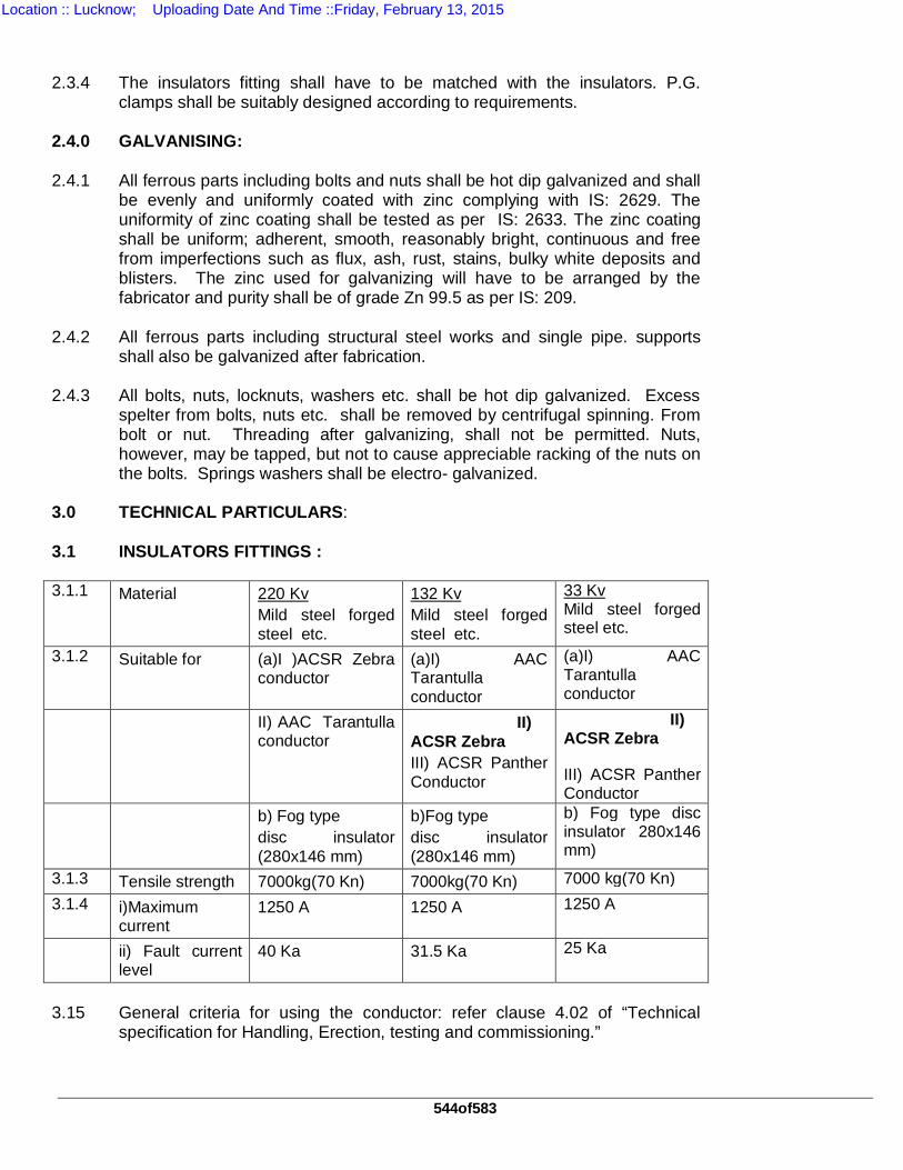
544of583
2.3.4 The insulators fitting shall have to be matched with the insulators. P.G.
clamps shall be suitably designed according to requirements. 2.4.0 GALVANISING: 2.4.1 All ferrous parts including bolts and nuts shall be hot dip galvanized and shall
be evenly and uniformly coated with zinc complying with IS: 2629. The uniformity of zinc coating shall be tested as per IS: 2633. The zinc coating shall be uniform; adherent, smooth, reasonably bright, continuous and free from imperfections such as flux, ash, rust, stains, bulky white deposits and blisters. The zinc used for galvanizing will have to be arranged by the fabricator and purity shall be of grade Zn 99.5 as per IS: 209.
2.4.2
All ferrous parts including structural steel works and single pipe. supports shall also be galvanized after fabrication.
2.4.3
All bolts, nuts, locknuts, washers etc. shall be hot dip galvanized. Excess spelter from bolts, nuts etc. shall be removed by centrifugal spinning. From bolt or nut. Threading after galvanizing, shall not be permitted. Nuts, however, may be tapped, but not to cause appreciable racking of the nuts on the bolts. Springs washers shall be electro- galvanized.
3.0 TECHNICAL PARTICULARS: 3.1 INSULATORS FITTINGS : 3.1.1 Material 220 Kv
Mild steel forged steel etc.
132 Kv Mild steel forged steel etc.
33 Kv Mild steel forged steel etc.
3.1.2 Suitable for (a)I )ACSR Zebra conductor
(a)I) AAC Tarantulla conductor
(a)I) AAC Tarantulla conductor
II) AAC Tarantulla conductor
II) ACSR Zebra III) ACSR Panther Conductor
II) ACSR Zebra
III) ACSR Panther Conductor
b) Fog type disc insulator (280x146 mm)
b)Fog type disc insulator (280x146 mm)
b) Fog type disc insulator 280x146 mm)
3.1.3 Tensile strength 7000kg(70 Kn) 7000kg(70 Kn) 7000 kg(70 Kn) 3.1.4 i)Maximum
current 1250 A 1250 A 1250 A
ii) Fault current level
40 Ka 31.5 Ka 25 Ka
3.15
General criteria for using the conductor: refer clause 4.02 of “Technical specification for Handling, Erection, testing and commissioning.”
Location :: Lucknow; Uploading Date And Time ::Friday, February 13, 2015
545of583
3.2
DOUBLE TENSION INSULATORS FITTINGS FOR TWIN MOOSE BUNDLE CONDUCTOR WITH BOLTED TYPE TENSION CLAMP.
Suitably designed insulator fitting with bolted type tension clamp shall be
offered. The clamp should be suitable for two point anchoring. The fitting should normally have following components. The tension clamp shall be suitably designed to take a static tension of 4000kg. The clevis, ball and socket for the disk insulators shall be as per I.E.C. specification 16 mm type. The material of construction shall be as under:
a) Shackles, Link
socket clevis -Forged steel
b) Yoke plate - Mild steel c) Angle plate -do- d) Corona control
rings - Mild steel tube (Minimum thickness 1.6 mm)
or Al. tube (Minimum thickness 2.5 mm) e) Turn buckle - Forged steel f) Tension clamp - Aluminum Alloy 3.3
SINGLE TENSION & SUSPENSION (STRING ) FITTINGS FOR MOOSE , PANTHER, ZEBRA ANDTARANTULLA CONDUCTORS
The material i.e. mild steel forged steel or malleable iron for these fittings
shall be such that it gives the required mechanical strength. The clamps should be of Aluminum Alloy and shall be designed to carry the same current as the conductor. All forging and casting shall be of good finish and free from flaws and other defects. The edges on the outside of fittings shall be rounded. All ferrous fittings and the parts other than those of stainless steel shall be galvanised. Spring washers nuts etc. may be electro-galvanised. All parts of different fittings which are provided for inter-connection shall be made such that sufficient clearance is provided at the connection joints to ensure free movement and suspension of spring insulator assembly.
Suspension clamps shall be so designed that the effects of vibration both on
the conductor and fittings itself are minimized. The clamps shall permit the conductor to slip before the failure of the conductor occurs. The fittings shall have sufficient contact surface to minimize damage due to fault currents. All nuts shall be made in accordance of IS-1367 or equivalent. Pins shall be made of forged steel and security dips shall be of phosphor bronze or brass. These tension and suspension fittings should meet the requirement of IS-2486 parts I & II or equivalent. The size of ball and clevis and socket shall be of 16 mm as per IS / IEC specification.
Location :: Lucknow; Uploading Date And Time ::Friday, February 13, 2015
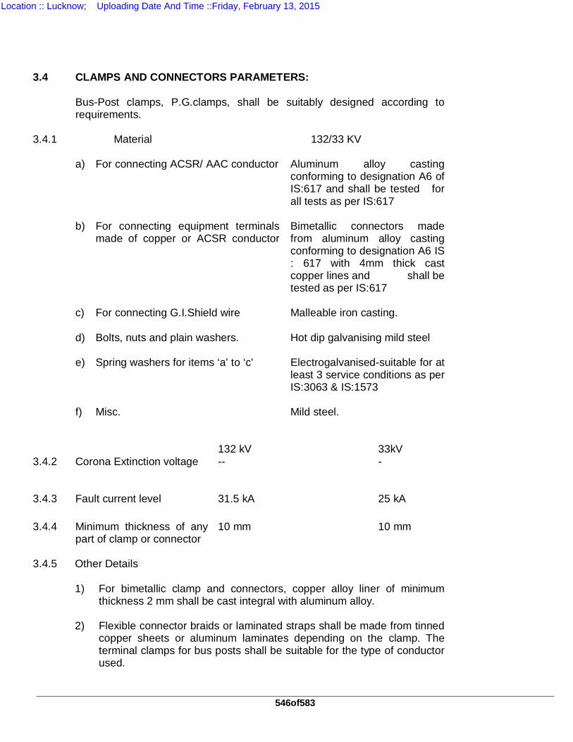
546of583
3.4 CLAMPS AND CONNECTORS PARAMETERS: Bus-Post clamps, P.G.clamps, shall be suitably designed according to
requirements. 3.4.1
Material 132/33 KV
a) For connecting ACSR/ AAC conductor Aluminum alloy casting conforming to designation A6 of IS:617 and shall be tested for all tests as per IS:617
b) For connecting equipment terminals
made of copper or ACSR conductor
Bimetallic connectors made from aluminum alloy casting conforming to designation A6 IS : 617 with 4mm thick cast copper lines and shall be tested as per IS:617
c) For connecting G.I.Shield wire Malleable iron casting. d) Bolts, nuts and plain washers. Hot dip galvanising mild steel e) Spring washers for items ‘a’ to ‘c’ Electrogalvanised-suitable for at
least 3 service conditions as per IS:3063 & IS:1573
f) Misc. Mild steel. 132 kV 33kV 3.4.2
Corona Extinction voltage -- -
3.4.3 Fault current level 31.5 kA 25 kA 3.4.4 Minimum thickness of any
part of clamp or connector 10 mm 10 mm
3.4.5 Other Details 1) For bimetallic clamp and connectors, copper alloy liner of minimum
thickness 2 mm shall be cast integral with aluminum alloy. 2) Flexible connector braids or laminated straps shall be made from tinned
copper sheets or aluminum laminates depending on the clamp. The terminal clamps for bus posts shall be suitable for the type of conductor used.
Location :: Lucknow; Uploading Date And Time ::Friday, February 13, 2015
547of583
3) Size of the terminal / conductor for which the clamp/connector is suitable
shall be embossed / punched (indelibly marked) on each component of the clamp/connector except on hardware.
4) Clamp shall be designed to carry the same current as the conductor and
the temperature rise shall be equal or less than that of the conductor at the specified ambient temperature. The rated current for which the clamp / connector is designed with respect to the specified reference ambient temperature shall also be indelibly marked on each component of one clamp / connector except on the insulator fittings.
4.0 TYPE AND ROUTINE TESTS: 4.1 Clamps & Connectors The type tests shall include the following but shall not be limited to the
following and shall be carried out on clamps and fittings without any extra cost to the Purchaser.
i) Test for corona inception and extinction voltages with and without
corona rings to be performed on completely assembled strings. ii) Radio Interference voltage test. iii) Corrosion and Galvanising test. iv) Dynamic High current withstand test. v) Tension Test. vi) Slip Test vii) Electrical Resistance test. viii) Heating cycle test. 4.2 The reports of following type tests, on the complete insulators string with
hardware fitting, shall need to be furnished. a) Power frequency voltage withstand test with
corona control rings and arcing horns (I) dry (ii) wet.
BS:137
b) Power frequency voltage flashover test with corona control rings and arcing horns (I) dry (ii) wet.
BS:137
c) Power frequency voltage flashover test without corona control rings and arcing horns (I). Dry (ii). Wet.
As per clause 7.0
d) Switching surge voltage withstand (wet) test. IEC-383 e) Impulse voltage withstand test. ) f) Impulse voltage flashover test. ) g) Voltage distribution test. )As per clause7.0
Location :: Lucknow; Uploading Date And Time ::Friday, February 13, 2015
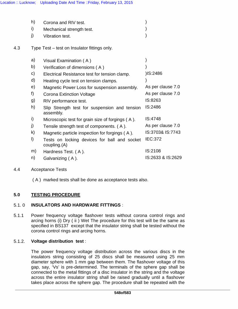
548of583
h) Corona and RIV test. ) i) Mechanical strength test. ) j) Vibration test. ) 4.3 Type Test – test on Insulator fittings only. a) Visual Examination ( A ) ) b) Verification of dimensions ( A ) ) c) Electrical Resistance test for tension clamp. )IS:2486 d) Heating cycle test on tension clamps. ) e) Magnetic Power Loss for suspension assembly. As per clause 7.0 f) Corona Extinction Voltage As per clause 7.0 g) RIV performance test. IS:8263 h) Slip Strength test for suspension and tension
assembly. IS:2486
i) Microscopic test for grain size of forgings ( A ). IS:4748 j) Tensile strength test of components. ( A ). As per clause 7.0 k) Magnetic particle inspection for forgings ( A ). IS:3703& IS:7743 l) Tests on locking devices for ball and socket
coupling.(A) IEC:372
m) Hardness Test. ( A ). IS:2108 n) Galvanizing ( A ). IS:2633 & IS:2629 4.4 Acceptance Tests ( A ) marked tests shall be done as acceptance tests also.
5.0 TESTING PROCEDURE 5.1. 0 INSULATORS AND HARDWARE FITTINGS : 5.1.1 Power frequency voltage flashover tests without corona control rings and
arcing horns (i) Dry ( ii ) Wet The procedure for this test will be the same as specified in BS137 except that the insulator string shall be tested without the corona control rings and arcing horns.
5.1.2. Voltage distribution test : The power frequency voltage distribution across the various discs in the
insulators string consisting of 25 discs shall be measured using 25 mm diameter sphere with 1 mm gap between them. The flashover voltage of this gap, say, ‘Vs’ is pre-determined. The terminals of the sphere gap shall be connected to the metal fittings of a disc insulator in the string and the voltage across the entire insulator string shall be raised gradually until a flashover takes place across the sphere gap. The procedure shall be repeated with the
Location :: Lucknow; Uploading Date And Time ::Friday, February 13, 2015
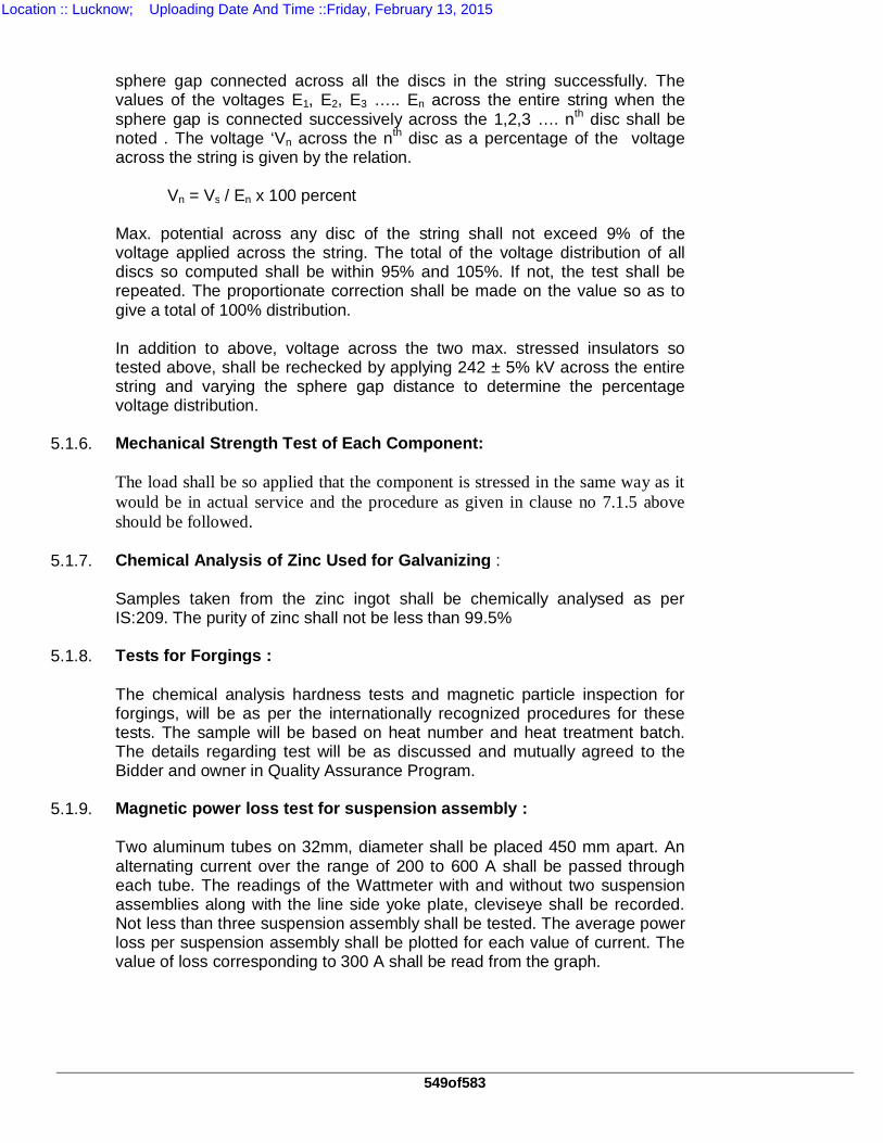
549of583
sphere gap connected across all the discs in the string successfully. The values of the voltages E1, E2, E3 ….. En across the entire string when the sphere gap is connected successively across the 1,2,3 …. nth disc shall be noted . The voltage ‘Vn across the nth disc as a percentage of the voltage across the string is given by the relation.
Vn = Vs / En x 100 percent Max. potential across any disc of the string shall not exceed 9% of the
voltage applied across the string. The total of the voltage distribution of all discs so computed shall be within 95% and 105%. If not, the test shall be repeated. The proportionate correction shall be made on the value so as to give a total of 100% distribution.
In addition to above, voltage across the two max. stressed insulators so
tested above, shall be rechecked by applying 242 ± 5% kV across the entire string and varying the sphere gap distance to determine the percentage voltage distribution.
5.1.6. Mechanical Strength Test of Each Component: The load shall be so applied that the component is stressed in the same way as it
would be in actual service and the procedure as given in clause no 7.1.5 above should be followed.
5.1.7. Chemical Analysis of Zinc Used for Galvanizing : Samples taken from the zinc ingot shall be chemically analysed as per
IS:209. The purity of zinc shall not be less than 99.5% 5.1.8. Tests for Forgings : The chemical analysis hardness tests and magnetic particle inspection for
forgings, will be as per the internationally recognized procedures for these tests. The sample will be based on heat number and heat treatment batch. The details regarding test will be as discussed and mutually agreed to the Bidder and owner in Quality Assurance Program.
5.1.9. Magnetic power loss test for suspension assembly : Two aluminum tubes on 32mm, diameter shall be placed 450 mm apart. An
alternating current over the range of 200 to 600 A shall be passed through each tube. The readings of the Wattmeter with and without two suspension assemblies along with the line side yoke plate, cleviseye shall be recorded. Not less than three suspension assembly shall be tested. The average power loss per suspension assembly shall be plotted for each value of current. The value of loss corresponding to 300 A shall be read from the graph.
Location :: Lucknow; Uploading Date And Time ::Friday, February 13, 2015
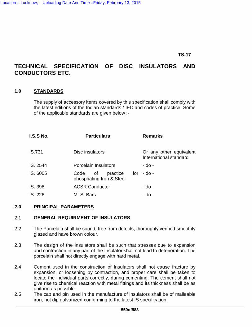
550of583
TS-17 TECHNICAL SPECIFICATION OF DISC INSULATORS AND CONDUCTORS ETC. 1.0 STANDARDS The supply of accessory items covered by this specification shall comply with
the latest editions of the Indian standards / IEC and codes of practice. Some of the applicable standards are given below :-
I.S.S No. Particulars Remarks
IS.731 Disc insulators Or any other equivalent International standard
IS. 2544 Porcelain Insulators - do -
IS. 6005 Code of practice for phosphating Iron & Steel
- do -
IS. 398 ACSR Conductor - do -
IS. 226 M. S. Bars - do - 2.0 PRINCIPAL PARAMETERS 2.1 GENERAL REQUIRMENT OF INSULATORS 2.2 The Porcelain shall be sound, free from defects, thoroughly verified smoothly
glazed and have brown colour. 2.3 The design of the insulators shall be such that stresses due to expansion
and contraction in any part of the Insulator shall not lead to deterioration. The porcelain shall not directly engage with hard metal.
2.4 Cement used in the construction of Insulators shall not cause fracture by
expansion, or loosening by contraction, and proper care shall be taken to locate the individual parts correctly, during cementing. The cement shall not give rise to chemical reaction with metal fittings and its thickness shall be as uniform as possible.
2.5 The cap and pin used in the manufacture of insulators shall be of malleable iron, hot dip galvanized conforming to the latest IS specification.
Location :: Lucknow; Uploading Date And Time ::Friday, February 13, 2015
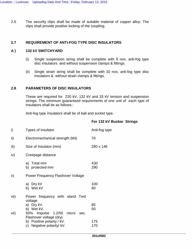
551of583
2.6 The security clips shall be made of suitable material of copper alloy. The
clips shall provide positive locking of the coupling.
2.7 REQUIREMENT OF ANTI-FOG TYPE DISC INSULATORS A ) 132 kV SWITCHYARD (i) Single suspension string shall be complete with 9 nos. anti-fog type
disc insulators and without suspension clamps & fittings. (ii) Single strain string shall be complete with 10 nos. anti-fog type disc
insulators & without strain clamps & fittings. 2.8 PARAMETERS OF DISC INSULATORS These are required for 220 kV, 132 kV and 33 kV tension and suspension
strings. The minimum guaranteed requirements of one unit of each type of insulators shall be as follows :
Anti-fog type insulators shall be of ball and socket type. For 132 kV Busbar Strings i) Types of insulator Anti-fog type ii) Electromechanical strength (kN) 70 iii) Size of Insulator (mm) 280 x 146 iv) Creepage distance a) Total mm 430 b) protected mm 290 v) Power Frequency Flashover Voltage a) Dry kV 100 b) Wet kV 60 vii) Power frequency with stand Test
voltage
a) Dry kV. 85 b) Wet kV. 50 vii) 50% Impulse 1.2/50 micro sec.
Flashover voltage (dry)
b) Positive polarity / kV. 175 c) Negative polarity/ kV. 170
Location :: Lucknow; Uploading Date And Time ::Friday, February 13, 2015
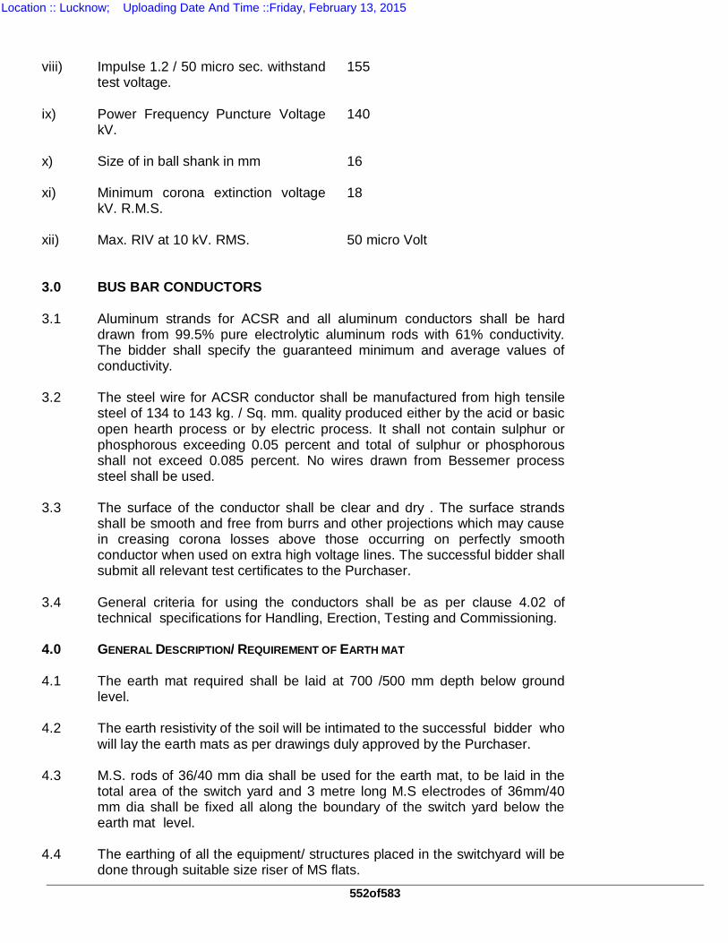
552of583
viii) Impulse 1.2 / 50 micro sec. withstand
test voltage. 155
ix) Power Frequency Puncture Voltage
kV. 140
x) Size of in ball shank in mm 16 xi) Minimum corona extinction voltage
kV. R.M.S. 18
xii) Max. RIV at 10 kV. RMS. 50 micro Volt 3.0 BUS BAR CONDUCTORS 3.1 Aluminum strands for ACSR and all aluminum conductors shall be hard
drawn from 99.5% pure electrolytic aluminum rods with 61% conductivity. The bidder shall specify the guaranteed minimum and average values of conductivity.
3.2 The steel wire for ACSR conductor shall be manufactured from high tensile
steel of 134 to 143 kg. / Sq. mm. quality produced either by the acid or basic open hearth process or by electric process. It shall not contain sulphur or phosphorous exceeding 0.05 percent and total of sulphur or phosphorous shall not exceed 0.085 percent. No wires drawn from Bessemer process steel shall be used.
3.3 The surface of the conductor shall be clear and dry . The surface strands
shall be smooth and free from burrs and other projections which may cause in creasing corona losses above those occurring on perfectly smooth conductor when used on extra high voltage lines. The successful bidder shall submit all relevant test certificates to the Purchaser.
3.4 General criteria for using the conductors shall be as per clause 4.02 of
technical specifications for Handling, Erection, Testing and Commissioning. 4.0 GENERAL DESCRIPTION/ REQUIREMENT OF EARTH MAT 4.1 The earth mat required shall be laid at 700 /500 mm depth below ground
level. 4.2 The earth resistivity of the soil will be intimated to the successful bidder who
will lay the earth mats as per drawings duly approved by the Purchaser. 4.3 M.S. rods of 36/40 mm dia shall be used for the earth mat, to be laid in the
total area of the switch yard and 3 metre long M.S electrodes of 36mm/40 mm dia shall be fixed all along the boundary of the switch yard below the earth mat level.
4.4 The earthing of all the equipment/ structures placed in the switchyard will be
done through suitable size riser of MS flats.
Location :: Lucknow; Uploading Date And Time ::Friday, February 13, 2015
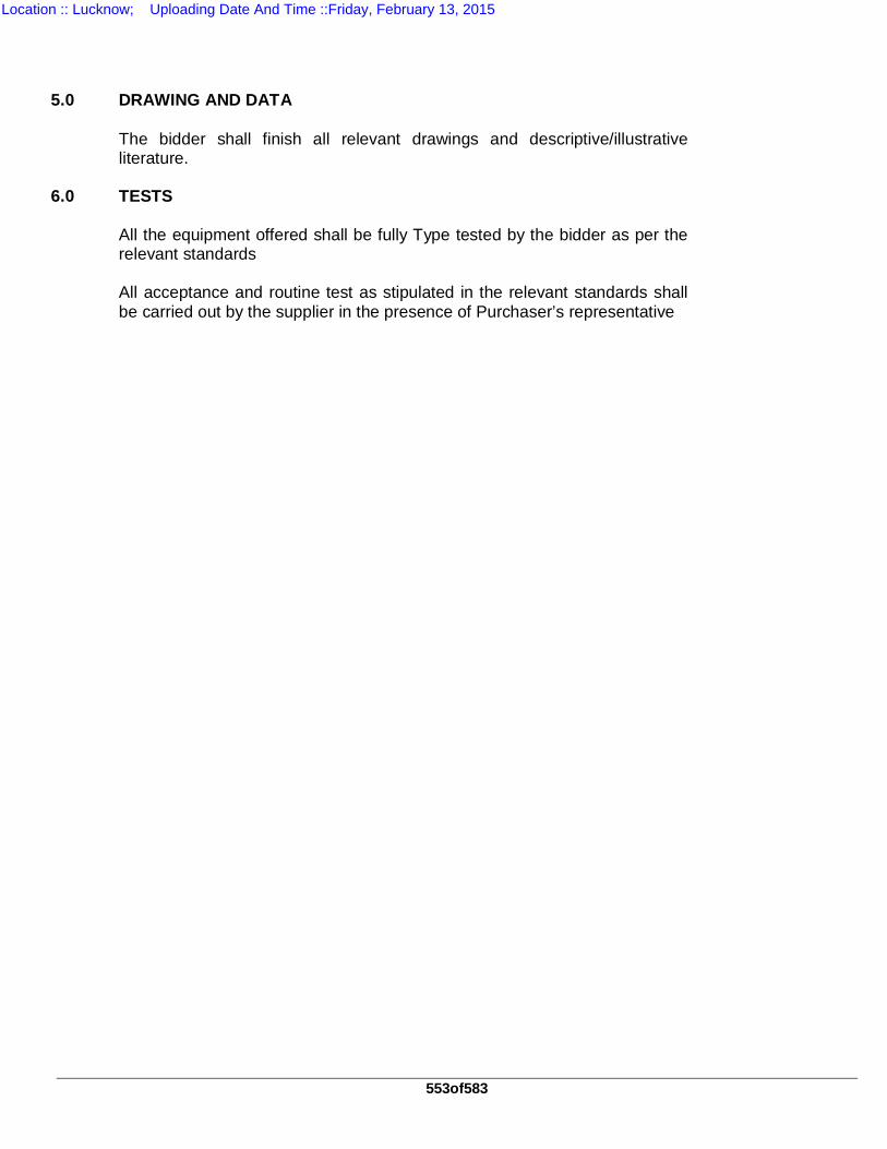
553of583
5.0 DRAWING AND DATA The bidder shall finish all relevant drawings and descriptive/illustrative
literature. 6.0 TESTS All the equipment offered shall be fully Type tested by the bidder as per the
relevant standards All acceptance and routine test as stipulated in the relevant standards shall
be carried out by the supplier in the presence of Purchaser’s representative
Location :: Lucknow; Uploading Date And Time ::Friday, February 13, 2015
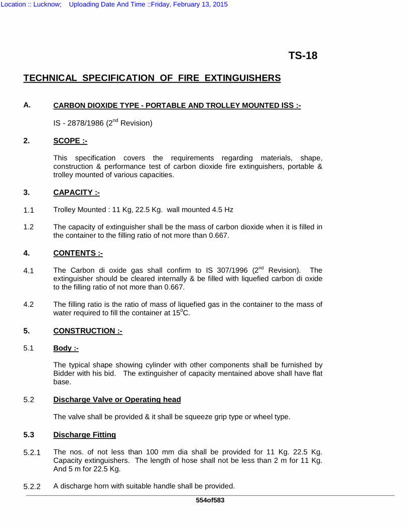
554of583
TS-18 TECHNICAL SPECIFICATION OF FIRE EXTINGUISHERS A. CARBON DIOXIDE TYPE - PORTABLE AND TROLLEY MOUNTED ISS :- IS - 2878/1986 (2nd Revision) 2. SCOPE :- This specification covers the requirements regarding materials, shape,
construction & performance test of carbon dioxide fire extinguishers, portable & trolley mounted of various capacities.
3. CAPACITY :- 1.1 Trolley Mounted : 11 Kg, 22.5 Kg. wall mounted 4.5 Hz 1.2
The capacity of extinguisher shall be the mass of carbon dioxide when it is filled in the container to the filling ratio of not more than 0.667.
4. CONTENTS :- 4.1
The Carbon di oxide gas shall confirm to IS 307/1996 (2nd Revision). The extinguisher should be cleared internally & be filled with liquefied carbon di oxide to the filling ratio of not more than 0.667.
4.2
The filling ratio is the ratio of mass of liquefied gas in the container to the mass of water required to fill the container at 150C.
5. CONSTRUCTION :- 5.1 Body :- The typical shape showing cylinder with other components shall be furnished by
Bidder with his bid. The extinguisher of capacity mentained above shall have flat base.
5.2 Discharge Valve or Operating head The valve shall be provided & it shall be squeeze grip type or wheel type. 5.3 Discharge Fitting 5.2.1 The nos. of not less than 100 mm dia shall be provided for 11 Kg. 22.5 Kg.
Capacity extinguishers. The length of hose shall not be less than 2 m for 11 Kg. And 5 m for 22.5 Kg.
5.2.2 A discharge horn with suitable handle shall be provided.
Location :: Lucknow; Uploading Date And Time ::Friday, February 13, 2015
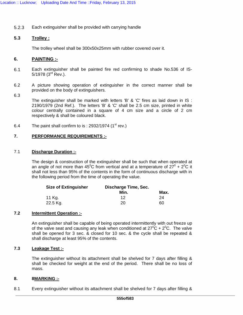
555of583
5.2.3 Each extinguisher shall be provided with carrying handle 5.3 Trolley : The trolley wheel shall be 300x50x25mm with rubber covered over it. 6. PAINTING :- 6.1
Each extinguisher shall be painted fire red confirming to shade No.536 of IS-5/1978 (3rd Rev.).
6.2
A picture showing operation of extinguisher in the correct manner shall be provided on the body of extinguishers.
6.3 The extinguisher shall be marked with letters 'B' & 'C' fires as laid down in IS :
2190/1979 (2nd Ref.). The letters 'B' & 'C' shall be 2.5 cm size, printed in white colour centrally contained in a square of 4 cm size and a circle of 2 cm respectively & shall be coloured black.
6.4 The paint shall confirm to is : 2932/1974 (1st rev.) 7.
PERFORMANCE REQUIREMENTS :-
7.1 Discharge Duration :- The design & construction of the extinguisher shall be such that when operated at
an angle of not more than 450C from vertical and at a temperature of 270 + 20C it shall not less than 95% of the contents in the form of continuous discharge with in the following period from the time of operating the value.
Size of Extinguisher Discharge Time, Sec. Min. Max. 11 Kg. 12 24 22.5 Kg. 20 60 7.2 Intermittent Operation :- An extinguisher shall be capable of being operated intermittently with out freeze up
of the valve seat and causing any leak when conditioned at 270C + 20C. The valve shall be opened for 3 sec. & closed for 10 sec. & the cycle shall be repeated & shall discharge at least 95% of the contents.
7.3 Leakage Test :- The extinguisher without its attachment shall be shelved for 7 days after filling &
shall be checked for weight at the end of the period. There shall be no loss of mass.
8. 8MARKING :- 8.1 Every extinguisher without its attachment shall be shelved for 7 days after filling &
Location :: Lucknow; Uploading Date And Time ::Friday, February 13, 2015
556of583
shall be checked for weight at the end of the period. There shall be no loss of
mass. 8.1.1 The following information shall be marked on the extinguishers : (a) Manufacture's name & trade mark. (b) Method of operation in prominent letters. (c) The word "CARBON DI OXIDE TYPE" in prominent letters. (d) Capacity. (e) Years of manufacture and (f) Source, year of manufacture of the cylinder & its test pressure. 8.1.2 The following information of facilitate filling or recharging shall also be marked on
the head of extinguisher or on the neck of the cylinder. (a) Empty Wt. of Cylinder shown as EW and (b) Filled Wt. of extinguisher shown ans FW. 8.1.3 The extinguisher may also be marked with the standard mark. 9. TEST PRESSURE :-
The pressure shall be 236 Kg. (B) DRY CHEMICAL POWDER TYPE FIRE EXTINGUISHER
1. ISS: 2171/1985 (3rd Rev) Ammendment No.1 2. SCOPE :
This specification covers the requirement regarding material shape, construction & performance test of Dry Chemical Powder (cardige) type.
3. CAPACITY :-
1X10 Kg. capacity extinguisher are in the form of portable (wall mounted) and 22.5 Kg. 45 Kg. Capacity extinguisher in trolly mounted. Various composition of dry powder such as Sodium & Potassium carbonates and bicarbonates, chlorides Ammonium Phosphate & borates etc. The latest powder developed on a reaction product of urea & potassium bicarbonate. The gas cartridge shall confirm to IS 4947/ 1977.
5. PRINCIPAL :- The dry chemical powder extinguisher extinguishes fire by beating displacement of
air and decomposition of dry powder in to carbonate dioxide.
Location :: Lucknow; Uploading Date And Time ::Friday, February 13, 2015
557of583
6. CONSTRUCTION :-
Body :
The typical shape showing cylinder with other components in shown in the fig. 3 enclosed. The extinguisher mentioned above shall have flat base. The outer cylinder dia shall be 175+5mm.
6.1 Discharge Vave : The valve shall be eithersqueez grip type or wheel type. 6.2 Discharge Fitting : 6.3.1 The neck ring dia of 75mm & length 16mm shall be provided. 6.3.2 Syphon tube of 1 mm thick & 16mm dia shall be provided. 6.3.3 Cartridge holder shall have female left handed threads corresponding to those of
cartridge, with port holes. 6.3.4 Each extinguisher shall be provided with carrying handle. 6.4 Trolley :- The details of trolley shall be submitted by the Bidder with his bid. The trolley
wheel shall be 300x50x25mm with rubber covered over it. 7. MATERIAL:- Following material is to be used for construction fire extinguisher. Sl.No. Component Material 1 Body Mild steel sheet 1.25mm thick 2 Inner Container Brass sheet.
3 Neck Ring Liquid Tin Bronze 4 Syphon tube Brass, Copper, Aluminium, 16mdia
71mm thick. 5 Hose The minimum bursting pressure shall
be 50 Kg/Cm2 6 Piercer/Spindle Steel 7 Spring Steel (Plated)
8. PAINTING :- 8.1
Each extinguisher shall be painted fire red confirming to shade No.536 of IS-5/1978 (3rd Rev.).
Location :: Lucknow; Uploading Date And Time ::Friday, February 13, 2015
558of583
8.2
A picture showing operation of extinguisher in the correct manner shall be provided on the body of extinguishers.
8.3
The extinguisher shall be marked with letters 'B' & 'C' indicating their suitability for respective classes of fires as laid down in IS: 2190/1979 (2nd Rev.) The letters 'B' & 'C' shall be 2.5 cm size printed in white colour centrally contained in a square of 4 cm size and a circle of 2 cm respectively & shall be coloured black.
8.4 The paint confirm to IS 2932/1974 91st Rev.) 9. EXPANSION SPACE :- An air space shall be provided in the body above the specified liquid level & shall
be of sufficient volume to ensure that when the discharge nozzle is temporarily closed and the extinguisher is put in to separation at a temp of (270 + 50C, the pressure exerted shall not exceed 1.5MN/M (15 Kgs/Cm)2.
10. ANTI CORROSION TREATMENT :- The body shall have all the internal surfaces completely coated with lead tin alloy
having tin not less than 10% applied by hot dipping process. The external surface shall be subjected to this anti corrosive treatment which shall be applied to a uniform thickness.
11. TEST REQUIREMENT :- 11.1
Under normal condition operation (270 + 50C,) the jet should maintain a flow of 4m for 5 Kg Capacity & 6m for 10 kg capacity) extinguisher.
11.2
There should be 85% discharge with in a maximum period of 22 Sec. For 5 Kg. Capacity & 30 sec. For 10 Kgs. Capacity 45 Sec. for 25 Kgs.
11.3
In case of hydraulic burst test, mechanical failure should not occur at a pressure not less then 4.5 MN/M2 (45Kg/Cm2).
11.4
The extinguisher body & the cap assembly shall be tested to an internal hydraulic test pressure of 3 MN/M2 (30Kg/Cm2).
11.4 The expansion space static pressure shall be 1.5 MN/M2 (15Kg/Cm2). 12. MARKING : The following marking shall be marked on the extinguisher
12.1 Method of operation in prominent letters. 12.2 The word "DRY CHEMICAL POWDER" in prominent letters. 12.3 Manufacture's name or trade mark. 12.4 Year of manufacture. 12.5 Test pressure & capacity in Kg.
Location :: Lucknow; Uploading Date And Time ::Friday, February 13, 2015
559of583
TECHNICAL SPECIFICATION OF FIRE BUCKETS 1. STANDARD ISS shall confirm to IS 2546/1974 1st Revision amendment No.1 Galvanized mild
steel fire bucket. 2 MATERIAL Galvanized mild steel shall be used. 3 CONSTRUCTION The fire bucket shall be round type i.e. its bottom portion shall be round & not flat
type as in case of ordinary bucket. The upper diameter & length shall be 250mm & 300mm respectively.
4 PAINTING The bucket shall be first painted with one coat of red Oxide primer and then with
two coats of synthetic enameled post office red paint from outside. Inside partition shall be painted with two coats of synthetic enameled white paint. The handle and out side bottom portion shall be painted with black paint Only BRITISH, ASIAN, SHALIMAR paint shall be used.
1.1 FIRE:- On one side the "FIRE” in 100mm height shall be written & on other side the word
^^vkx^* in same height, shall be written. The thickness of each alphabet in English as well as in Hindi shall be 050 mm. Only Capital letters shall be used.
Location :: Lucknow; Uploading Date And Time ::Friday, February 13, 2015
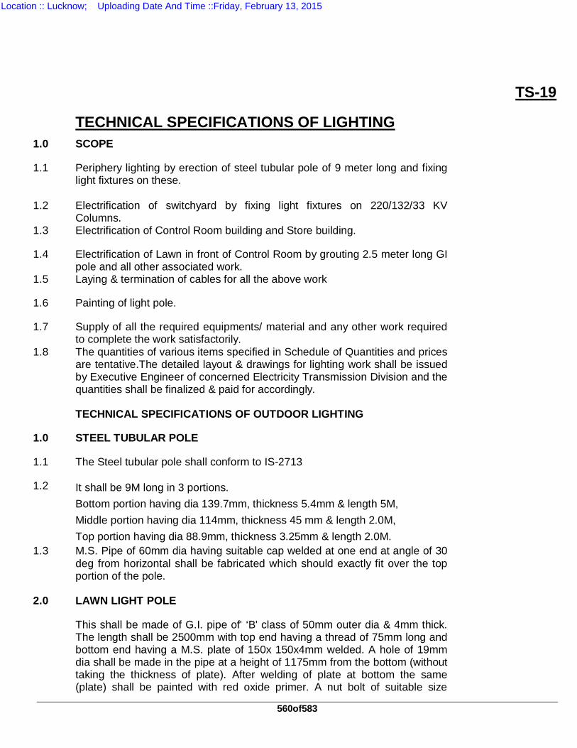
560of583
TS-19
TECHNICAL SPECIFICATIONS OF LIGHTING 1.0 SCOPE
1.1 Periphery lighting by erection of steel tubular pole of 9 meter long and fixing light fixtures on these.
1.2 Electrification of switchyard by fixing light fixtures on 220/132/33 KV Columns.
1.3 Electrification of Control Room building and Store building.
1.4 Electrification of Lawn in front of Control Room by grouting 2.5 meter long GI pole and all other associated work.
1.5 Laying & termination of cables for all the above work
1.6 Painting of light pole.
1.7 Supply of all the required equipments/ material and any other work required to complete the work satisfactorily.
1.8 The quantities of various items specified in Schedule of Quantities and prices are tentative.The detailed layout & drawings for lighting work shall be issued by Executive Engineer of concerned Electricity Transmission Division and the quantities shall be finalized & paid for accordingly.
TECHNICAL SPECIFICATIONS OF OUTDOOR LIGHTING
1.0 STEEL TUBULAR POLE
1.1 The Steel tubular pole shall conform to IS-2713
1.2 It shall be 9M long in 3 portions. Bottom portion having dia 139.7mm, thickness 5.4mm & length 5M, Middle portion having dia 114mm, thickness 45 mm & length 2.0M, Top portion having dia 88.9mm, thickness 3.25mm & length 2.0M.
1.3 M.S. Pipe of 60mm dia having suitable cap welded at one end at angle of 30 deg from horizontal shall be fabricated which should exactly fit over the top portion of the pole.
2.0 LAWN LIGHT POLE
This shall be made of G.I. pipe of' ‘B' class of 50mm outer dia & 4mm thick. The length shall be 2500mm with top end having a thread of 75mm long and bottom end having a M.S. plate of 150x 150x4mm welded. A hole of 19mm dia shall be made in the pipe at a height of 1175mm from the bottom (without taking the thickness of plate). After welding of plate at bottom the same (plate) shall be painted with red oxide primer. A nut bolt of suitable size
Location :: Lucknow; Uploading Date And Time ::Friday, February 13, 2015
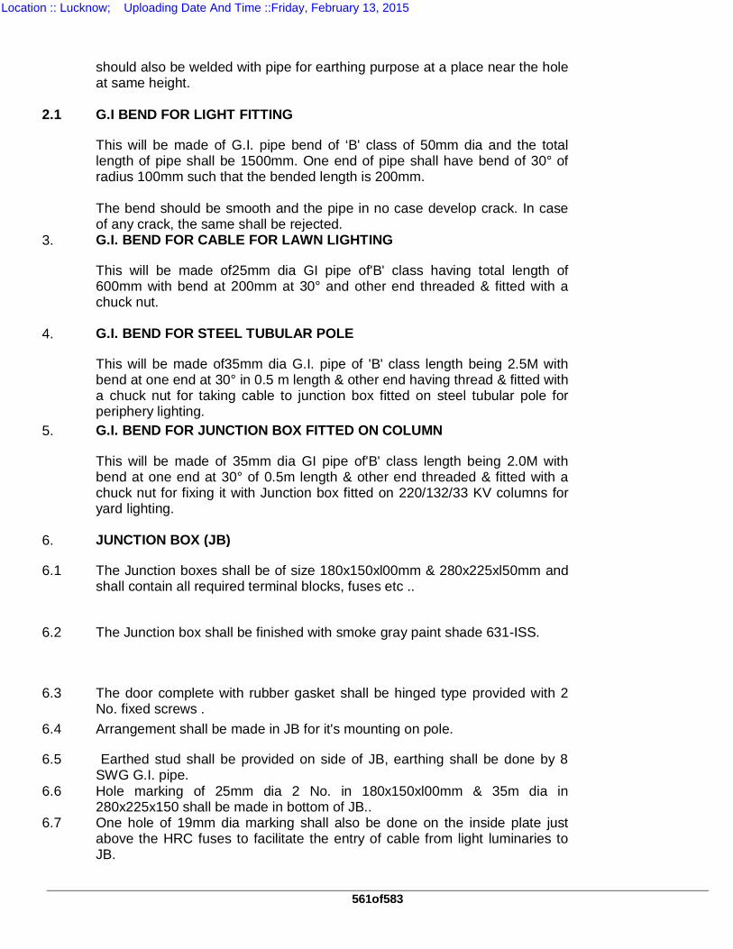
561of583
should also be welded with pipe for earthing purpose at a place near the hole at same height.
2.1 G.I BEND FOR LIGHT FITTING
This will be made of G.I. pipe bend of ‘B' class of 50mm dia and the total length of pipe shall be 1500mm. One end of pipe shall have bend of 30° of radius 100mm such that the bended length is 200mm. The bend should be smooth and the pipe in no case develop crack. In case of any crack, the same shall be rejected.
3. G.I. BEND FOR CABLE FOR LAWN LIGHTING
This will be made of25mm dia GI pipe of'B' class having total length of 600mm with bend at 200mm at 30° and other end threaded & fitted with a chuck nut.
4. G.I. BEND FOR STEEL TUBULAR POLE
This will be made of35mm dia G.I. pipe of 'B' class length being 2.5M with bend at one end at 30° in 0.5 m length & other end having thread & fitted with a chuck nut for taking cable to junction box fitted on steel tubular pole for periphery lighting.
5. G.I. BEND FOR JUNCTION BOX FITTED ON COLUMN
This will be made of 35mm dia GI pipe of'B' class length being 2.0M with bend at one end at 30° of 0.5m length & other end threaded & fitted with a chuck nut for fixing it with Junction box fitted on 220/132/33 KV columns for yard lighting.
6. JUNCTION BOX (JB)
6.1 The Junction boxes shall be of size 180x150xl00mm & 280x225xl50mm and shall contain all required terminal blocks, fuses etc ..
6.2 The Junction box shall be finished with smoke gray paint shade 631-ISS.
6.3 The door complete with rubber gasket shall be hinged type provided with 2 No. fixed screws .
6.4 Arrangement shall be made in JB for it's mounting on pole.
6.5 Earthed stud shall be provided on side of JB, earthing shall be done by 8 SWG G.I. pipe.
6.6 Hole marking of 25mm dia 2 No. in 180x150xl00mm & 35m dia in 280x225x150 shall be made in bottom of JB..
6.7 One hole of 19mm dia marking shall also be done on the inside plate just above the HRC fuses to facilitate the entry of cable from light luminaries to JB.
Location :: Lucknow; Uploading Date And Time ::Friday, February 13, 2015
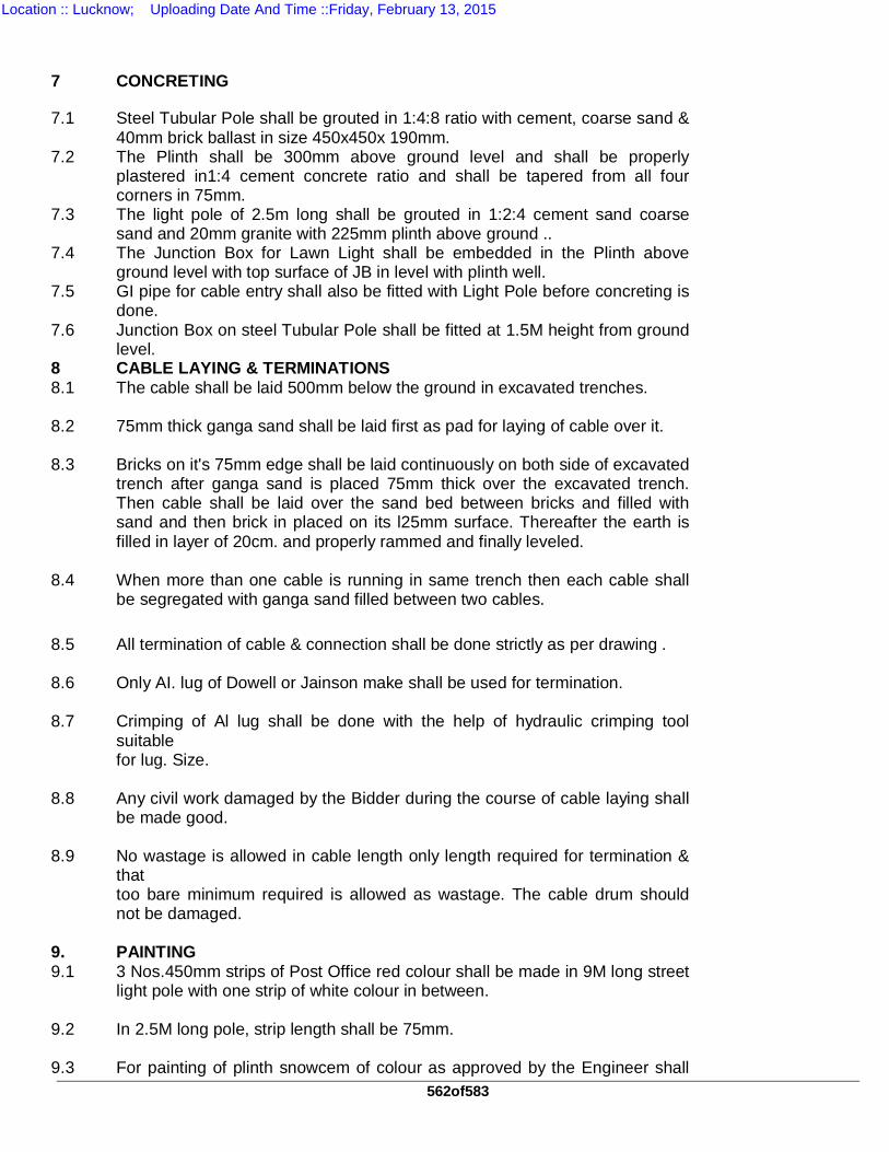
562of583
7 CONCRETING
7.1 Steel Tubular Pole shall be grouted in 1:4:8 ratio with cement, coarse sand & 40mm brick ballast in size 450x450x 190mm.
7.2 The Plinth shall be 300mm above ground level and shall be properly plastered in1:4 cement concrete ratio and shall be tapered from all four corners in 75mm.
7.3 The light pole of 2.5m long shall be grouted in 1:2:4 cement sand coarse sand and 20mm granite with 225mm plinth above ground ..
7.4 The Junction Box for Lawn Light shall be embedded in the Plinth above ground level with top surface of JB in level with plinth well.
7.5 GI pipe for cable entry shall also be fitted with Light Pole before concreting is done.
7.6 Junction Box on steel Tubular Pole shall be fitted at 1.5M height from ground level.
8 CABLE LAYING & TERMINATIONS 8.1 The cable shall be laid 500mm below the ground in excavated trenches. 8.2 75mm thick ganga sand shall be laid first as pad for laying of cable over it. 8.3 Bricks on it's 75mm edge shall be laid continuously on both side of excavated
trench after ganga sand is placed 75mm thick over the excavated trench. Then cable shall be laid over the sand bed between bricks and filled with sand and then brick in placed on its l25mm surface. Thereafter the earth is filled in layer of 20cm. and properly rammed and finally leveled.
8.4 When more than one cable is running in same trench then each cable shall
be segregated with ganga sand filled between two cables. 8.5 All termination of cable & connection shall be done strictly as per drawing . 8.6 Only AI. lug of Dowell or Jainson make shall be used for termination. 8.7 Crimping of Al lug shall be done with the help of hydraulic crimping tool
suitable for lug. Size.
8.8 Any civil work damaged by the Bidder during the course of cable laying shall
be made good. 8.9 No wastage is allowed in cable length only length required for termination &
that too bare minimum required is allowed as wastage. The cable drum should not be damaged.
9. PAINTING 9.1 3 Nos.450mm strips of Post Office red colour shall be made in 9M long street
light pole with one strip of white colour in between. 9.2 In 2.5M long pole, strip length shall be 75mm. 9.3 For painting of plinth snowcem of colour as approved by the Engineer shall
Location :: Lucknow; Uploading Date And Time ::Friday, February 13, 2015
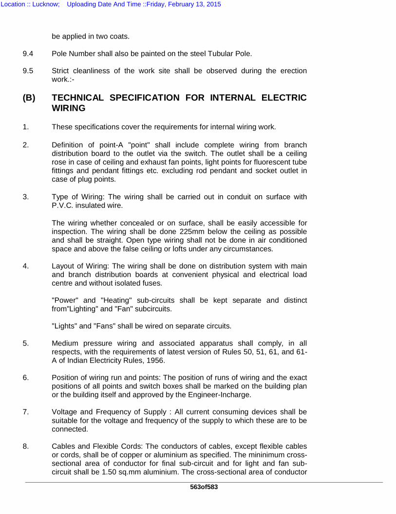
563of583
be applied in two coats.
9.4 Pole Number shall also be painted on the steel Tubular Pole. 9.5 Strict cleanliness of the work site shall be observed during the erection
work.:- (B) TECHNICAL SPECIFICATION FOR INTERNAL ELECTRIC
WIRING 1. These specifications cover the requirements for internal wiring work. 2. Definition of point-A "point" shall include complete wiring from branch
distribution board to the outlet via the switch. The outlet shall be a ceiling rose in case of ceiling and exhaust fan points, light points for fluorescent tube fittings and pendant fittings etc. excluding rod pendant and socket outlet in case of plug points.
3. Type of Wiring: The wiring shall be carried out in conduit on surface with
P.V.C. insulated wire. The wiring whether concealed or on surface, shall be easily accessible for
inspection. The wiring shall be done 225mm below the ceiling as possible and shall be straight. Open type wiring shall not be done in air conditioned space and above the false ceiling or lofts under any circumstances.
4. Layout of Wiring: The wiring shall be done on distribution system with main
and branch distribution boards at convenient physical and electrical load centre and without isolated fuses.
"Power" and "Heating" sub-circuits shall be kept separate and distinct
from"Lighting" and "Fan" subcircuits. "Lights" and "Fans" shall be wired on separate circuits. 5. Medium pressure wiring and associated apparatus shall comply, in all
respects, with the requirements of latest version of Rules 50, 51, 61, and 61-A of Indian Electricity Rules, 1956.
6. Position of wiring run and points: The position of runs of wiring and the exact
positions of all points and switch boxes shall be marked on the building plan or the building itself and approved by the Engineer-Incharge.
7. Voltage and Frequency of Supply : All current consuming devices shall be
suitable for the voltage and frequency of the supply to which these are to be connected.
8. Cables and Flexible Cords: The conductors of cables, except flexible cables
or cords, shall be of copper or aluminium as specified. The mininimum cross-sectional area of conductor for final sub-circuit and for light and fan sub-circuit shall be 1.50 sq.mm aluminium. The cross-sectional area of conductor
Location :: Lucknow; Uploading Date And Time ::Friday, February 13, 2015
564of583
for the wiring of high pressure mercury/sodium vapour lamp and exhaust fan shall be 2.5sq.mm aluminium. The minimum cross-sectional area of conductor for power wiring shall be 4 sq .mm. aluminium or 2.5 sq.mm copper.
9. Rating of lamps and Fans: As far as possible, actual current carried by any
conductor should be estimated. Unless the actual value of load is known, a light point shall be rated at 100 W in non-residential buildings and 60 W in residential buildings table fans and ceilings fans at 60 W, 5 A socket outlet at 60 W and 15 A power outlet at 100 W. Exhaust fans shall be rated according to their capacity.
10. Looping back : The wiring shall be done in looping back system without any
connector or junction box on the line. The looping back of phase or live conductor shall be done at the switch box and that of neutral at the light, fan or socket outlet. In no case, joint shall be made bare or by twisting the conductors in through runs of' cables. If the length of final sub-circuit, sub~main or main is more than the length of standard coil and joint becomes unavoidable, such joints shall be made by means of proper connector. No junction box shall be provided specific difficulties should be referred to Engineer-In-charge for decision.
11. Control at a point of commencement of supply : A circuit breaker or a linked
main switch with fuse on each live conductor shall be provided at the point of entry at an accessible place, as near as practicable to the termination of service line. There shall be no break on the neutral wire except at the switch gear. No fuse shall be provided in the earthed neutral conductor. The neural shall be distinctly marked.
12. Metal Boxes: Metal boxes made of cast iron shall be 3mm thick. The sheet
steel boxes shall be made of 1.5mm (16 SWG) thick mild steel sheet. These boxes shall have not less than four screwed holes for fixing the top cover and a earthing stud. These boxes shall be provided with a cover of phenolic laminated sheet, not less than 3 mm thick, fastened to the box with not less than four number brass screws and washers. These boxes shall be painted both inside and outside, with two coats of antirust paint.
13. Fixing of fittings and accessories: In case of conduit wiring, all accessories
like switches sockets, call bell pushes regulators etc. shall be of piano type. These shall be mounted on phenolic laminated cover fixed on cast iron or mild steel box of suitable size. The accessories and regulators shall be mounted in flush type pattern or as directed by Engineer-in-charge.
14. Conduit Wiring System: This type of wiring can be used both for low voltage
and medium voltage installation. Single core PVC insulated (without sheath) cable shall be used. This cable shall be drawn in heavy gauge rigid steel conduit. The conduits shall be fixed on surface.
(I) Surface conduit wiring system - Heavy gauge rigid steel conduit, solid
drawn or lapwelded, with galvanized or stove enameled surface, not less than 19mm in diameter, shall be used. The gauge of conduits shall be not less than 1.5mm (16 SWG). for conduit of size upto 32mm diameter and not
Location :: Lucknow; Uploading Date And Time ::Friday, February 13, 2015
565of583
less than 2mm (14 SWG) for conduit of size above 32mm diameter. Only threaded type conduit accessories shall be used. Pin grip or clamp type accessories shall not be used under any circumstances. The maximum number of PVC insulated 1100 volt grade aluminium conductor cables that can be drawn in conduit shall be specified.
In case of cables carrying alternating current the outgoing and return cables
shall be drawn in the same conduit. The conduit pipe shall be joined by means of screwed socket, couples, or
accessories only. Inspection boxes and inspection type couplers shall be provided at intervals not exceeding 6meters. Threads on the conduit pipe shall be long enough to accommodate the pipe to full threaded portion of the couplers and accessories. No burrs or sharp edges shall be left at the curt end of the conduit pipes to avoid damages to the insulation of the conductors while pulling.
The layout of the conduit shall be such that condensation or sweating inside
the conduit, if occurs, is drained out. In order to minimize it all outlets of the conduit system shall be ventilated, keeping covers of the inspection boxes exposed but flushed in level.
The conduit pipe for each circuit shall be erected before any cable is drawn
in. The conduit pipes shall be fixed by heavy gauge steel saddles, secured over 12mm thick spacers of well seasoned teakwood/approved MDF, at intervals not exceeding 60cm. The spacer shall be fixed to wall plug by flat headed wood screws. A saddle shall be fixed within 10cm. on both sides of couplers, bends or similar other fittings. The saddle shall be not less than 24 gauge thick for conduit pipe up to 15mm diameter and not less than 10 gauge thick for conduits of larger diameter.
When conduits have to be attached to irons or steel joints or pillars, suitable
girder clips at intervals of 60cm shall be secured by means of ordinary clips or girders clips, as required. Where it is not possible to drill holes, suitable clamps with bolts and nuts shall be linked. The clips shall be not less than 19mm wide and 0.90mm thick for conduit pipe up to 25mm diameter. For all sizes of clamping rod shall be 4.45 mm (7SWG) diameter).
All necessary bends in the system including diversion shall be done by
bending pipe, or by inserting suitable solid inspection type normal bends, elbows or similar fittings or by fixing cast iron or sheet inspection boxes as directed by Engineer-Incharge. Conduit fittings shall be avoided, as far as possible, on conduit system exposed to weather, where necessary, solid type fittings shall be used, radius of such bends in conduit pipes shall be not less than 7.5cm. No length of conduit shall have more than the equivalent of four quarter bends from outlet to outlet.
The conduit of each circuit or section shall be completed before conductors
are drawn in. The entire conduit system shall be electrically and mechanically continuous and shall be tested for the same. The entire system shall be permanently connected to earth in general conformity to the requirement of earthing G.I. earth continuity wire of 8SWG size shall run along the full-length
Location :: Lucknow; Uploading Date And Time ::Friday, February 13, 2015
566of583
of the conduit and shall be fastened,to conduit between each wire and conduit, and terminated in the box with stud. Gas or water pipes shall not be used as earthing medium. If conduit pipes are liable to mechanical damage, they shall be adequately protected. When passing through walls or floors, conduit pipes shall be continuous. The metal box shall be efficiently earthed with the conduit by means of approved couplers. Only a portion of the box shall be sunk in the wall, the remaining portion shall project out of entry of conduit pipe into the box. The clear depth of the box shall be not less than 6cm. Where fan regulator is also be accommodated, the depth shall be increased to accommodate the fan regulator in flush pattern. Standard conductors shall be preferred in conduit wiring.
After completion of erection, the portion of the building damaged during the
erection of the installation shall be repaired properly to meet the original finish and colour of the walls and ceiling etc.
15. Capacity of Sub-Circuits: Light and fans shall be wired on separate sub-
circuits. Not more than a total often light plug points or four to six fan points shall be provided in a sub-circuit.The load on a sub-circuit shall be restricted to 800 watts.
The power sub-circuit shall be designed according to the said requirement of
the subcircuit.. 16. Passing through walls and floors : (I) When the conductors pass through
walls, they shall be taken through one piece of heavy gauge rigid steel conduit or porcelain pipe or corrugated or solid P.V.C. pipe extending through the whole thickness of the wall. The ends shall be bushed properly. the pipe or conduit shall be of adequate six so that the wires pass through a straight line without any twist of cross in wires.
(II) When the pipe extends outside the building, the portion exposed to
weather shall be well mouthed, turned downwards and properly bushed on the open ends.
17. Fittings and accessories: (I) Ceiling roses and similar attachments: A ceiling
rose shall not embody fuse terminals as integral part of it. A ceiling rose or similar attachments shall be used in low voltage installations only. (II) Socket outlet and plugs: Every socket outlet shall be controlled by a switch which shall be on the live side of the line and shall preferably by located immediately adjacent there to or combined therewith. A socket outlet shall not embody fuse terminal as an integral part of it but the fuse may be embodied in plug.
In an earthed system of supply, three pin type socket outlet, with the third pin
connected to earth, shall be used. The connection from such outlet to any current consuming device shall be done by means of 3 core flexible cords, one end of the earthing core of which shall be connected to the earthing pin and the other to earthing point of the current consuming device. Every plug containing a fuse shall be nonreversible and shall be so arranged and connected that the fuse controls an outer phase conductor or the non-earthed conductor of the circuit.
Location :: Lucknow; Uploading Date And Time ::Friday, February 13, 2015
567of583
18. Main switches and switch boards : (1) All main switchgears shall be metal
clad and shall be installed in dry situation, as near as practicable to the point of supply.
18.1 The main switch will have a fuse on each live conductor of supply mains. No
fuse shall be provided in the earthed neutral. The neutral wire shall be continuous except at the linked switch gear.
18.2 The bottom of switch board shall be more than 1.25 metres above the floor
level unless the front of switch board is completely enclosed by a door or the switch board is located in a position to which only authorized persons have access.
18.3 Equipments which are on the front of a switch board shall be so arranged
that inadvertent personal contact with live part is avoided during the maintenance of switch gear changing of fuse or like operations.
18.4 The switches shall be so arranged that fuses are not "alive" when the switch
is in the ... OFF .... position. 18.5 A danger notice plate shall be provided on switch boards connected to
medium voltage supply and above. 19. Main and branch distribution Boards: 19.1 The main and branch distribution fuse boards shall be of metalclad type.
These shall be of weather proof type for exposed to whether or damp situation and flame proof type for situations exposed to explosive dust, vapour or gas.
19.2 Main distribution boards shall be controlled either by a linked switch fuse or
circuit breaker. Each outgoing circuit shall be provided with a fuse on the phase or live conductor.
19.3 Branch distribution boards shall be controlled by a linked switch fuse or
circuit breaker. Each outgoing circuits of the branch distribution board shall be provided with a fuse on the phase or live conductor. The earthed neutral conductor shall be connected to a common link and be capable of being disconnected individually for testing purpose. At least one spare circuit of the same capacity shall be provided on each distribution board.
19.4 The distribution fuse boards shall be installed as near the centre of load as
possible, in dry opened at a time and the metal case is marked "DANGER" "415 Volts" or installed in a room or enclosure accessible to authorized persons only.
20. Wiring of distribution boards 20.1 The load coming on the distribution board shall be divided as far as possible,
evenly between the number of ways of the boards. One spare circuit should be left for future extension.
Location :: Lucknow; Uploading Date And Time ::Friday, February 13, 2015
568of583
20.2 All connections between pieces of apparatus or between apparatus and
terminals on a board shall be neatly arranged in a definite sequence following the arrangements of the apparatus mounted thereon, avoiding unnecessary crossings.
20.3 Cables should be connected to terminals only by soldered lugs crimped lugs
or clamped securely without cutting away the cable strands. 20.4 All the conductors shall be rigidly fixed in such a manner that clearance of at
least 25mm is maintained between conductors of opposite polarity or phases and between the conductors and any other materials other than insulating material.
20.5 The incoming and outgoing cables shall be neatly bunched and fixed properly
permitting the board to swing back fully. 20.6 The current rating of fuse shall not exceed the current rating of the fuse
carrier or the current rating of the smallest cable in the circuit protected by the fuse.
20.7 Boards for mounting switch gear: One of the following types of boards shall
be used for mounting metal clad switch gear. 20.8 Hinged type metal boards: These types of boards shall be used for low
voltage installation for mounting metal clad switchgear consisting of not more than one switch fuse and one single phase and neutral distribution fuse board. These boards shall consist of a box made of sheet steel not less than 3mm thick. Alternatively, a frame of angle iron of minimum size 35mm x 6mm or channel of minimum size 35mm X 25mm X 6mm for these boards shall be made and mild steel plate of 3mm thickness mounted on the front and 1.6mm thickness on the back. The joints shall be substantially welded. The boards shall be provided with locking arrangement and earthing stud. If so required in any work atleast 6mm thick wooden board of well seasoned polished M.D.F. exterior grades board shall be provided at the back. There shall be a clearance of 30mm minimum between the front and back covers.
No apparatus shall project beyond the edge of the board. No fuse shall be
mounted within 5mm of the board edge. The boards shall be painted with synthetic enamel paint over anti-rust
priming coat. The boards shall be securely fixed to the wall by means of rag bolts or wood
plugs. 21 Lighting fittings Lights, fans and socket outlets shall be so located as to provide, maximum
comfort to the occupant and to enable him to utilize the electricity in the most economical manner. Every fitting shall be controlled by a switch which shall be in live conductor of the circuit. Where control of the fitting at more than one point is necessary .it shall be done by as many two way and intermediate switches as there are control points.
Location :: Lucknow; Uploading Date And Time ::Friday, February 13, 2015

569of583
Fittings Wire: These wires shall be of copper and shall be used only for
internal wiring of fittings and shall be carried up to the termination of the light point.
Fluorescent tube fittings: These fittings shall be high power factor type i.e. shall consist of necessary power factor improvement capacitor. The capacitor shall be of 2.4 mfd for fittings suitable for single tube and 3.15 mfd. for fittings suitable for double tubes. The fittings shall be of standard models complete with necessary number of tubes and not economical models. These shall be complete with all components supplied as original components with standard models and shall be assembled and wired by the manufactures at the factory. The fluorescent tube shall be of the same make as the fitting. In cases where tubes are not manufactured by the fittings manufacturers the fluorescent tube of any approved make as directed by the Engineer In charge shall be used.
Lamp Holders: All lamp holders shall be bayonet cap type and shall be
provided with shade carrier. Height of fittings : Unless desired otherwise, all wall mounting and pendent
fittings inside the building shall be kept at a height of 2.5 metres above the floor level. All fittings outside the building and on roads shall be fixed at the height as directed by the Engineer-in charge.
Rod pendent fittings shall be suspended with heavy gauge rigid steel conduit
pipe duly painted of appropriate size electroplated steel chains of required length as directed by the Engineer in charge.
22 EARTHING General-Earthing shall confirm to the following specifications. For other
details not covered in these specifications, relevant Indian Standards shall be referred to I.S.: 3043,1965 (Code of Practice for Earthing).
Earthing shall generally be carried out in accordance with the requirements of
Indian Electricity Rules, 1956 as amended from time to time and the relevant regulations of the Electricity supply authority concerned. The following clauses of the Indian Electricity Rules, 1956 are particularly applicable 32, 51, 61, 61 A, 62, 67,69,88(2) & 90.
All earth connections shall be visible for inspection. All materials, fittings etc. used in earthing shall confirm to the Indian
standards specifications wherever these exist. In the case of materials for which I.S.S. do not exist, the same will be approved by the Engineer-in-charge
No earth electrode shall have a ohmic resistance greater than five ohms as
measured by an approved earth testing apparatus. In rocky soils, the resistance may be upto eight ohms.
Normally, an earth electrode shall not be situated less than 1.5m away from
any building.
Location :: Lucknow; Uploading Date And Time ::Friday, February 13, 2015
570of583
The location of the earth electrode will be such where the soil has reasonable
chance of remaining moist, as far as possible. Entrances, pavements and roadways, are to be definitely avoided for location of the earth electrode.
TYPE OF EARTH ELECTRODES a) Pipe earth electrode. G.I. pipe shall be of 40mm dia 4.5 metres in length. Galvanising of the pipe
shall conform to relevant Indian Standards. The pipe shall have a clean surface, not covered by paint, enamel or poorly conducting material. The pipe shall be of one piece. G.I. pipe electrode shall be compared at the bottom and provided with holes of 12 mm dia drilled and spaced 75mm from each other up to 2 metres of length from bottom. The electrode shall be buried in the ground vertical with it's top not less than 20 cm below ground level.
Watering arrangement:- In the case of pipe electrode a 40mm x 20mm
reducer shall be used for fixing the funnel. The watering funnel attachment shall be housed in masonary, enclosure not less than 300mm deep. A 300mm x 300mm cast iron cover frame with hinged cover having locking arrangement shall be suitably embedded in the masonary enclosure.
b) Artificial treatment of soil The electrode shall be surrounded by charcoal/coke and salt in alternate
layers not less than 150rnm thick. c) Earthing lead: Main earthing lead: The main earthing lead shall be of G.I. wire or G.I. strip in
case of G.I. plate earth electrode. - For all electrical installations, except sub-stations and generating stations,
the earthing lead shall be not less than one-half of cross-sectional area of the largest conductor to be protected. A conductor larger than 100sq.rnm nominal crosssectional area (2/0 SWG) in case of copper conductor and 150 sq.mm in case of G.I. conductor need not be used.
The minimum size of main earthing, lead shall not be less than 8 SWG
copper or G.I. wire, or 12mm x 3mm copper or G.I. strip. d) Earth continuity conductor: The nominal cross sectional area of an earth
continuity conductor not contained within a cable or flexible cord shall be 14 SWG copper or 12SWG G.I. or 4 sqmm aluminium wire.
The earthing lead in the case of pipe earth electrode, shall be connected by means of a through G.I. bolts, nuts and washers and cable sockets as indicated in the drawing. All material used for connection the earth lead with electrode shall be of GI in case of G.I. pipe. The earthing lead shall be securely connected at the other end to the main board.
Loop earthing shall be provided for all mounting.
Location :: Lucknow; Uploading Date And Time ::Friday, February 13, 2015
571of583
Protection of earthing lead. The earthing of main board and other metal clad
switches and distribution fuse boards with not less than 14 SWG copper or 12 SWG GI or 4sqmm aluminium wire lead from electrode onwards shall be suitably protected from mechanical injury by a 15mm dia G.I. pipe in case of wire.
23. COMPLETION REPORT After completion of the installation the test results and completion report of
the installation work shall be submitted 24. TESTING OF INSTALLATION: 24.1 General The following tests in sequence shall be carried out on completion and the
defects revealed shall be made good: Polarity test. Insulation resistance test. Earth continuity test. Earth electrode resistance test. Where ever any addition is made to the fixed wiring of an earthing
installation, both the addition and that part of existing installation relating thereto should be tested. Polarity test of non-linked single pole switch
In a low voltage installation a test shall be made to that all non-linked, single
pole switches have been in the same conductor throughout and that such conductor has been connected to an outer or phase conductor or conductor or to the non-earthed conductor of the...............
Insulation resistance test : (1) The insulation resistance shall be measured by
applying between earth and the whole of conductor or any section thereof with all fuses and all switches closed and except in earthed electric wiring, all lamps in position or both poles of installation otherwise electrically connected together a voltage of not less than twice the working voltage. It shall not exceed 500 volts for medium circuit.
Insulation resistance in meg-ohms of an installation (1) shall be not less than
50 divided by number of points on the circuit, provided that the installation need not be required to have insulation greater than one meg-ohm.
Insulation of an electric installation (or an extension installation) a certificate shall be furnished by Bidder, countersigned by the certified supervisor, in direct supervision of whom the installation was carried. The certificate shall be in a prescribed form as specified by the local electric supply authority
Earth continuity path : The earth continuity of metal conduits and metallic envelopes of cables shall be tested for electric continuity and resistance of the same along with earthing including any added resistance or earth leakage measured from, the connection with the earth at any point in the earth continuity conductor in the installation shall not exceed 10 ohm.
Location :: Lucknow; Uploading Date And Time ::Friday, February 13, 2015
572of583
TS – 20
TECHNICAL SPECIFICATIONS FOR 63KVA DIESEL GENERATOR
The scope of work includes the supply and installation of 1x 63kVA Diesel Generator (DG) set mounted inside the Substation generator room and associated works. The outgoing cables shall be sized to suit the DG output. 1.0 GENRAL
This specification covers the turnkey installation of 1 x 63kVA standby diesel generating system covering the diesel engine, alternator, engine control panel, associated accessories, cooling system, ventilation system, fuel and exhaust system, acoustic enclosure and switchgear etc. The contractor shall assume full responsibility of co-coordinating the work with various sub-vendors and other contracting agencies at site and execute the work to the total satisfaction of the clients and statutory agencies.
2.0 SITE CONDITIONS:
Location : Various substation in Uttar Pradesh
Design Maximum Ambient Temperature : 50 deg C Minimum Ambient Air Temperature in shade : 0 deg C
Relative Humidity : 100% Max. Wind Load : 195 Kg/sq.m. Slismic Level : 0.3g Isoceraunic Level : 50 days/Year Average Annual Rainfall : 1200mm Altitude : Not exceeding
1000 m. Hot and humid tropical climate conductive to rust and fungus growth.
3.0 ELECTRICAL SUPPLY SPECIFICATIONS
Nominal voltage : 415V ±10% No. of Phases : 3 + Neutral Frequency : 50Hz ± 5% Neutral earthing : Solidly Grounded Control supply : 12 / 24V, 2-wire DC
4.0 SCOPE OF WORK & EXCLUSIONS
Location :: Lucknow; Uploading Date And Time ::Friday, February 13, 2015
573of583
The scope of work shall include but not be limited to the supply, installation, testing and commissioning of the following items. The supplier shall study the requirements stipulated in the specification and also to suit the site conditions and offer a complete system with guaranteed performance under the severest operating conditions specified. a. 415V, 3-phase + Neutral, 63kVA 1500 RPM, DG set with accessories as specified. b. Set mounted microprocessor based engine control panel. c. Radiator cooling system. d.Exhaust piping including supports. e.Thermal insulation for exhaust piping. f. Exhaust stacks with steel supporting system. g. Preparation of related schematic and GA drawings for DG installation, exhaust piping, ventilation system, etc. h. Obtaining Diesel Engine manufacturer’s approval of the installation with specific emphasis on alignment, exhaust & fuel piping and ventilation before commissioning. i. Testing and commissioning of the installation.
j. House keeping during the installation work and removal of debris and unwanted materials on a day to day basis and clearing the site on completion.
k.Any related work covering supply of installation materials, consumables, etc. whether specified for not, to render the system fully functional and conforming to the best engineering standards. This shall include battery charging.
5.0 DIESEL ENGINE & ACCESSORIES 5.1 ENGINE a. The diesel engines shall be of approved make, direct injection, four
stroke, multi cylinder, water cooled radiator type, turbo charged, operating at a nominal speed of 1500 R.P.M and capable of developing requisite Brake Horse Power (BHP).
b. The engine and the governing system shall be suitable for standby and Automatic Mains Failure (AMF) duty power generating application and shall conform to BS5514 / relevant ISS / IEC / ISO3046. The unit shall be suitable for operation on high speed diesel oil available in the Indian market.
c. The engine shall be electric start and shall be suitable for battery assisted manual / auto starting.
d. The governing system of the engine shall be electronic type and suitable to control frequency variation within ± 5% whenever the load is switched in or thrown off.
e. The engine fittings shall include but not be limited to the following: i) Closed coupling and flywheel with guard. ii) Dry type air filter with clogged condition indicator. iii) Cooling radiator.
Location :: Lucknow; Uploading Date And Time ::Friday, February 13, 2015
574of583
iv) Fuel pump. v) Electronic governor. vi) Dual fuel filter with online filter changing provision. vii) Lube oil pump, oil cooler and filter. viii) Turbo charger. ix) 12 / 24V DC starter & battery charging alternator. x) Engine mounted microprocessor based control panel to display the following minimum engine and electrical parameters:
a. Lube oil pressure indicator and temperature gauge. b. Tacho meter for speed indication with hour meter. c. Battery charging Ammeter. d. Starting switch with key. e. Over speed stop switch with contacts. f. Low lube oil pressure switch. g. High water temperature alarm & trip
xi) Wiring harness using temperature resistant insulation and flexible copper conductor
wires. The wiring should be clamped at regular intervals and terminated using lugs and terminals. xii) Stainless steel flexible for engine exhaust. xiii) Stop solenoid.
f. The engine speed shall be regulated through an electronic governing system which shall also provide the over speed protection. The governor shall ensure that the speed of the set is regulated within 1% of the nominal speed under normal operating conditions.
h. The DG set shall be capable of handling step load up to 70% of the capacity without dropping other loads due to voltage dips. Further the engine shall be capable of taking full load within 10 seconds of starting.
i. All moving parts of the engine and other associated equipment shall be provided with guards to prevent accidental contact. The guard shall be designed to facilitate easy removal and reinstallation.
j. The engine supplied with first filling of oil of required quantity as recommended by the manufacture
5.2 ACCESSORIES
The following accessories shall be supplied with the DG set. a.Common base frame for the engine and alternator. b.Antivibration mounts of requisite capacity. c.Residential silencer. d. Protective guards for all rotating parts. e.Electric driven lube oil priming pump complete with hosepipes and
couplers. f.Diesel tank with capacity to last 12 hours on 100% load. Capacity fabricated out of 1.5-3mm thick sheet steel including first filling of diesel. The tank shall be further complete with overflow pipe, drain pipe, fuel level indicator, valves, low level contact and alarm. g.Galvanized sheet steel trays beneath the engine and day tank to
collect the leakage oil. h. Batteries
Location :: Lucknow; Uploading Date And Time ::Friday, February 13, 2015
575of583
The batteries shall be of heavy duty, high performance lead acid type of Exide make or equivalent. Each battery shall be rated 12 / 24V. The number and AH capacity shall be selected to suit the engine requirements. Battery shall be suitable for six successive starting attempts each of 10 seconds duration with a gap of 5 seconds between successive starts. The battery shall be supplied complete with electrolyte and accessories. The accessories shall include battery stand, battery leads with terminal Tends acrylic top cover and inter battery connectors. The charger shall allow the battery to be charged when the set is not running. The charger shall get disconnected from the mains when the generator set is running. i. Control Panel The DG shall be supplied with an engine mounted Microprocessor based control panel. The control panel shall display all the engine, alternator & battery parameters. It shall not only display faults but also keep a record of faults. An emergency stop push button will be provided to stop the DG during emergency. For Engine faults, the set will be stopped in emergency mode & for electrical faults it shall be stopped with a time delay for cooling down. An audible alarm shall be provided in the main panel to announce tripping of DG. j. Alarms :The following alarms shall be provided in the DG control Panel to indicate & protect against abnormal operations. Condition Status Function Low Oil Pressure 2 stage Alarm Engine Stop High Water Temperature 2 stage Alarm Engine Stop Over Speed Alarm Engine Stop Low Fuel Level Day tank Alarm High Fuel Level Day tank Alarm Earth fault on Alternator Alarm Engine Stop Fail to start Alarm Battery charger fault Alarm
6.0 ALTERNATOR
1500 RPM, 415V, 3-Phase, 150 kVA, star-connected, 50Hz, 0.8 P.F, horizontal foot mounted, double bearing, self excited, self-regulated, brushless, screen protected drip proof, continuous duty alternator with class TH. insulation in IP22 enclosure incorporating the following. a. Continuous damper winding. b. One anti-condensation heater wired to a separate terminal box. c. Pilot exciter. d. 3 Phase sensing AVR with + 0.5% voltage regulation. e. A neutral CT of adequate ratio and class for REF relay for DG
Protection. 6.1 The Alternator shall further meet the following specifications:
a.The alternator shall conform to BS2613. b.The alternator shall be suitable for 20% over speed for two minutes. c.The alternator shall be capable of carrying 50% overload for a
duration of one minute. d.The alternator shall be capable of carrying 10% overloading for one hour Tin any period of 12 hrs running. e.The inertia constant shall be 0.26 second or above. f.The alternator terminal voltage for any load variation should be
Location :: Lucknow; Uploading Date And Time ::Friday, February 13, 2015
576of583
maintained within + 5%. g.The prime mover response should be such that with 150kW load throw TOFF / ON for the generator both transient and steady state frequency variation should be within + 3%. The generator terminal voltage for this load variation should be maintained with + 5%. h.The field coil terminals shall be wired to terminal box for external
speed control. i.Both ends of each phase winding shall be brought to the terminal
box. j.The alternator shall withstand a 3-phase short circuit at the terminals for a period of 3 seconds. k.The total harmonic distortion shall not exceed 3% and the design shall permit up to 30% unbalance between phases while in operation
6.2 Performance
Under normal operating conditions, the sound pressure levels when measured Tat a distance of one (1) metre outside the DG building shall be not more than 70 dB.
6.3 Painting' The entire system shall be coated with grey oxide paint. After erection rust preventive painting must be essential. After erection one coat of Dark Green color synthetic enamel must be
applied. 7.0 DIMENSIONS As per drawing of Generator room to be developed by tenerder 8.0 SPARES
The DG set will be supplied with the following spares, which shall be handed over at the time of commissioning. 2 sets of renewable parts of oil, fuel & air filters 2 Nos. fan belts 5 Nos. spare fuses of each type & size used 5 spare relays of each type 1 set of fuel injectors 1 No. Operators manual 1 No. Service manual
9.0 INSTALLATION The bidder shall undertake the installation work at site. The general scope of installation work shall include but not be limited to the following:
9.1 Diesel Generator Set
a.The assembled DG set shall be installed on anti-vibration mounts. The unit shall be visually inspected for any transit damage. b.The contractor shall arrange for the inspection of the set by the diesel engine manufacturer.s authorized representative and obtain This approval before rolling the set. c.The fuel oil day tank shall be installed over the drip tray at the
location indicated. d. The batteries shall be fully charged, installed, and connected. e. The battery charger shall be heavy duty.
9.2 Exhaust Piping' a.The exhaust piping shall be fabricated from 1.5-3mm thick mild steel
Tpipes. b.The exhaust piping and the silencers shall be insulated using 50mm thick mineral wool inside the container &up to the exhaust stack. The insulation shall be cladded with 24G aluminium sheet.
Location :: Lucknow; Uploading Date And Time ::Friday, February 13, 2015
577of583
c.The exhaust pipe shall be supported using spring suspension
supports. d.The shipping sections of the stack shall be welded at site and erected over the mild steel frame work. The entire length including flanges, bolts and washers shall be aluminised inside and outside to inhibit corrosion. A weather cowl shall be provided on top. e All tools and tackles used for the erection shall have valid safety
certification. 9.3 Electrical Installation
a. The electrical power cabling from alternator to the panel will be carried out by the representative of Engineer of The Contract. However the DG control cabling from the DG to the DG Panel will be carried out by the DG vendor.
b.The contractor shall appoint an experienced full time engineer throughout the installation period till the set is handed over. Three
month maintenance from the date of commissioning shall be carried out by the DG vender. c.The contractor shall carry out the control cabling from the engine control panel to the breakers in the main panel. d.Connecting block with wiring diagram shall be provided in the DG Panel for integrating with local LT system
10.0 TESTING 10.1 At Manufacturer.s works the routine tests and full load test on Engine,
and Alternator shall be carried out at the manufacturer.s work in accordance with applicable Indian standards.
The following tests shall be conducted: a.Full load testing for 8 hours with load bank. b.Overload testing at 10% overload for one hour immediately after the
full load test. c.Operation of protective devices.
10.2 Site Testing'
Following tests shall be conducted at site in the presence of the Engineer of Contracts.s representative before energisation. The contractor shall provide all testing equipment, labour and consumables required for the testing.
a.Checking the alignment by engine manufacturer.s representative and obtaining approval. b. Insulation resistance test on alternator, control panel and cabling /
bus bar trunking. c.Checking the Automatic Mains Failure (AMF) operation both on auto and manual mode. d. Checking the engine safeties for satisfactory operation. e.Checking vibration levels. f.Testing of individual protective devices on engine and alternator and ensuring that the wiring is carried out properly.
Location :: Lucknow; Uploading Date And Time ::Friday, February 13, 2015
578of583
g.Full load running for 8 hours continuously. All the readings shall be logged to evaluate the fuel consumption, lube oil pressure, water & oil temperature vis-à-vis the electrical load. h.One hour overload testing at 110% load shall be carried out at the end of the full load trial. i.The guaranteed specific fuel consumption shall not exceed 150 grams / BHP. HR with a tolerance of + 2.5 %. The same shall be proved during the load trial.
j.The noise level at 1m from the enclosure and the temperature rise inside the enclosure shall be measured.
k.Any deviation from the guaranteed parameters shall be made good and these performance parameters should be measured once again till the required results are achieved.
l.The DG set shall be deemed to be commissioned after satisfactory performance of all associated equipment.
11.0 GUARANTEE 11.1 Diesel Generator Set
The DG set and accessories shall be guaranteed for satisfactory operation for a period of 24 months from the date of commissioning or 5000 running hours from the date of supply whichever is earlier. Any defects noticed during this period shall be rectified free of cost. The supplier shall indicate the type of records to be maintained so that the warranty claims if any are honoured by the manufacturer.
12.0 MAINTENANCE
The bidder shall be required to maintain the installation at no extra cost to the owner for a period of two year from the date of commissioning. During this period, the contractor shall make good any defects caused due to faulty design, bad workmanship and poor quality of materials.
13.0 DOCUMENTATION
As a part of the equipment supply, following documentation shall be furnished
a. General arrangement plan of DG set. b.Exhaust fabrication drawing. c.Layout of exhaust piping. d.Engine wiring diagram. e.Test certificate for engine and alternator. f. Installation, operation and maintenance instructions for diesel
engine and alternator. g.Spare parts list.
14.0 SCHEDULE OF TECHNICAL PARTICULARS
All the installation shall fully conform to the requirement stipulated and the tests shall be carried out as stipulated. Deviations if any, shall be clearly brought out in the tender.
Location :: Lucknow; Uploading Date And Time ::Friday, February 13, 2015
579of583
15.0 STANDARDS
IS : 9537 – 1981 Rigid Steel Conduits for electrical wiring (Second Revisions)
IS : 10810 – 1988 Methods of test for cables. IS : 13947 – 1993 Degree of protection provided by enclosures for LV
switchgear and control gear. IS : 13947 – 1993 General requirement for switchgear and control gear for voltage not exceeding 1000 Volts. IEC60034 BS – 5000 Alternator IS : 694 -1990 PVC insulated Electric cable for working voltage upto
and including 1100 volts.
IS : 732 -1989 Code of practice for electrical wiring and installation IS : 1554 -1988 ( Part PVC insulated ( Heavy Duty) electric cables for
working voltages-I ) upto and including 1100 volts. IS : 1651 & 1652 – 1991 Stationary cell & batteries, lead acid type. IS : 1885 – 1971 Glossary of items for electrical cables and
conductors IS : 2551-1982 Danger notice plates. IS : 3043 – 1987 Code of practice for earthing. IS : 3480 -1966 Flexible steel conduits for electrical wiring. IS : 5133 – 1969 (Part -I) Boxes for the enclosure of electrical
accessories. IS : 5578 & 1984 Guide for marking of insulated conductors IS : 8130 -1984 Conductors for insulated electric cables and flexible
cords
Location :: Lucknow; Uploading Date And Time ::Friday, February 13, 2015
580of583
TS – 21
TECHNICAL SPECIFICATIONS FOR Bay Marshalling Kiosk
A maximum of two nos. Bay Marshalling Kiosks shall be installed on the 132 KV side of the switchyard. The Bay Marshalling Kiosks shall have two distinct compartments for the following purpose:
a. To receive two incoming 415V, phase, 63 Amps AC supply with auto changeover and MCB unit and distribute minimum isx outgoing 415V, 3 phase, 16 Amps AC supplies controlled by MCB.
b. Two distribute minimum ten outgoing 240V, 10 Amps single phase supplies to be controlled by MCB to be drawn from above 3 phase incomers.
A total of 200 nos. terminal blocks in vertical formation for interlocking facilities shall be available in each Bay Marshalling Kiosks.
Location :: Lucknow; Uploading Date And Time ::Friday, February 13, 2015