Embed Size (px)
Citation preview
V 1 . 0 p u b l i s h e d o n 0 1 . 2 0 1 7
LUCCI
CLIMATE
DC CEILING FAN
⚫ INSTALLATION ⚫ OPERATION ⚫ MAINTENANCE ⚫ WARRANTY INFORMATION
CAUTION
READ INSTRUCTIONS CAREFULLY FOR SAFE
INSTALLATION AND FAN OPERATION.
Climate Installation Instructions
1 | P a g e
CONGRATULATIONS ON YOUR PURCHASE
Congratulations on purchasing the latest in energy saving ceiling fans. This fan runs on DC (direct current) power which gives it the benefit of being super energy efficient whilst still maintaining high volume air-movement and silent operation. Energy Saving - The DC motor is the latest technology in fan design. Its highly efficient motor saves up to 65% more energy than ceiling fans with traditional AC motors. Silent operation – This DC fan motor is programmed with a stabilised current which efficiently reduces motor noise. Low operating temperature – The DC power is managed effectively which brings down the motor operating
temperature to less than 50℃. This results in a much cooler motor than a standard AC fan and increases the
longevity of the motor. 6 speed remote control - Regular AC ceiling fans usually come with only 3 speeds, this DC fan comes complete with a 6 speed remote, which gives greater choice of comfort levels.
SAFETY PRECAUTIONS
Read and Save These Instructions
This product conforms to UL standard 507.
1. WARNING -To avoid possible electrical shock, before installing or servicing your fan, disconnect the
power by turning off the circuit breaker of the fuse box to the outlet box.
2. WARNING - To reduce the risk of fire, electric shock, or personal injury, mount to outlet box marked
“acceptable for fan support of 35 lbs (15.9 kg) or less” and use the mounting screws provided with the
outlet box and/or support directly from building structure. Most outlet boxes commonly used for the
support of luminares may not be acceptable for fan support and may need to be replaced. Consult a
qualified electrician if in doubt.
3. WARNING - To reduce the risk of fire or electric shock, do not use this fan with any solid-state speed
control device.
4. WARNING - To reduce the risk of personal injury, do not bend the blade brackets when installing the
blade brackets balancing the blades, or cleaning the fan. Do not insert foreign objects in between rotating
fan blades.
5. CAUTIONS - All wiring must be in accordance with the National Electrical Code (ANSI/NFPA 70) and
local electrical codes. Electrical installation should be performed by a qualified licensed electrician.
6. To reduce the risk of injury to person, the fan must be mounted with a minimum of 7 feet clearance from
the bottom edge of the blades to the floor.
7. After marking electrical connections, spliced conductors should be turned upward and pushed carefully
up into outlet box. The wires should be spread apart with the grounded conductor and the equipment-
grounding conductor on one side of the outlet box.
8. This equipment has been tested and found to comply with the limits for a Class B digital device, pursuant
to part 15 of the FCC rules. These limits are to provide reasonable protection against harmful interference
in a residential installation. This equipment generates, uses and can radiate radio frequency energy and
if not installed and used in a ccordance with the instructions may cause harmful interference to radio
communicaitons.
Climate Installation Instructions
2 | P a g e
PARTS LIST
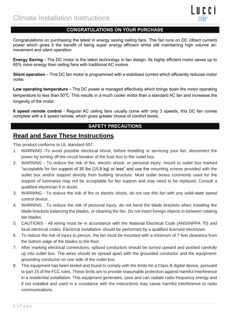
Unpack your fan and check the contents. You should have the following:
A. Mounting bracket x 1
G. Remote transmitter with holder x 1 set
(12V 23AE Battery included)
B. Fan assembly with hanger cover, down rod,
canopy cover and canopy x 1
H. Blade screw x 13
C. Bottom cover x 1
I. Motor screws x 9
D. Blade x 4
J. Mounting screw bag:
• Wood screw x 2
• Machine screw x 2
• Flat washer x 2
• Wire nut x 5
E. Blade holder x 4
F. Blade holder kit x 4
K. Balancing kits x 1 set
Fig. 1
Climate Installation Instructions
3 | P a g e
INSTALLING THE MOUNTING BRAKCET
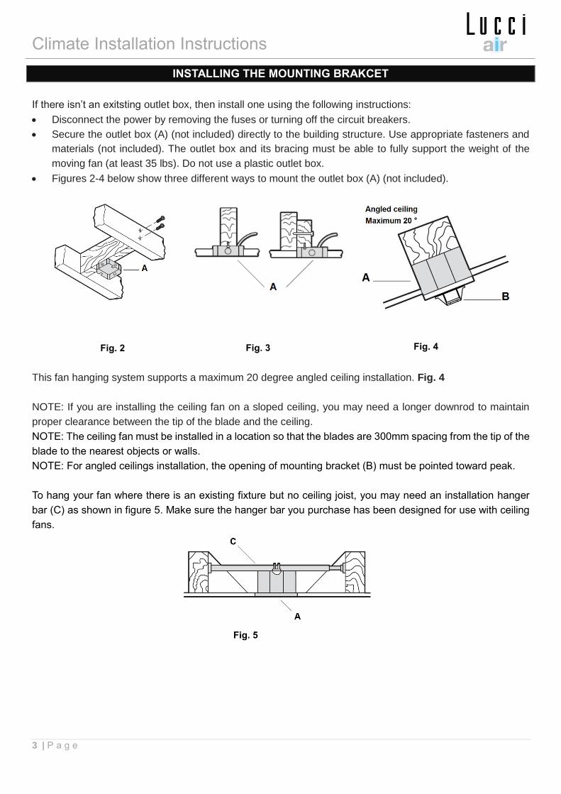
If there isn’t an exitsting outlet box, then install one using the following instructions:
• Disconnect the power by removing the fuses or turning off the circuit breakers.
• Secure the outlet box (A) (not included) directly to the building structure. Use appropriate fasteners and
materials (not included). The outlet box and its bracing must be able to fully support the weight of the
moving fan (at least 35 lbs). Do not use a plastic outlet box.
• Figures 2-4 below show three different ways to mount the outlet box (A) (not included).
This fan hanging system supports a maximum 20 degree angled ceiling installation. Fig. 4
NOTE: If you are installing the ceiling fan on a sloped ceiling, you may need a longer downrod to maintain
proper clearance between the tip of the blade and the ceiling.
NOTE: The ceiling fan must be installed in a location so that the blades are 300mm spacing from the tip of the
blade to the nearest objects or walls.
NOTE: For angled ceilings installation, the opening of mounting bracket (B) must be pointed toward peak.
To hang your fan where there is an existing fixture but no ceiling joist, you may need an installation hanger
bar (C) as shown in figure 5. Make sure the hanger bar you purchase has been designed for use with ceiling
fans.
Fig. 2
Fig. 5
Fig. 3 Fig. 4
Climate Installation Instructions
4 | P a g e
HANGING THE FAN
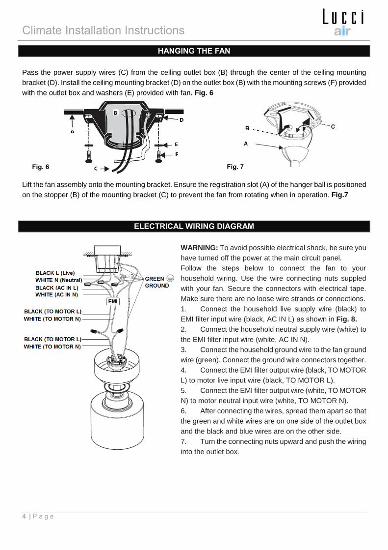
Pass the power supply wires (C) from the ceiling outlet box (B) through the center of the ceiling mounting
bracket (D). Install the ceiling mounting bracket (D) on the outlet box (B) with the mounting screws (F) provided
with the outlet box and washers (E) provided with fan. Fig. 6
Lift the fan assembly onto the mounting bracket. Ensure the registration slot (A) of the hanger ball is positioned
on the stopper (B) of the mounting bracket (C) to prevent the fan from rotating when in operation. Fig.7
ELECTRICAL WIRING DIAGRAM
WARNING: To avoid possible electrical shock, be sure you
have turned off the power at the main circuit panel.
Follow the steps below to connect the fan to your
household wiring. Use the wire connecting nuts suppled
with your fan. Secure the connectors with electrical tape.
Make sure there are no loose wire strands or connections.
1. Connect the household live supply wire (black) to
EMI filter input wire (black, AC IN L) as shown in Fig. 8.
2. Connect the household neutral supply wire (white) to
the EMI filter input wire (white, AC IN N).
3. Connect the household ground wire to the fan ground
wire (green). Connect the ground wire connectors together.
4. Connect the EMI filter output wire (black, TO MOTOR
L) to motor live input wire (black, TO MOTOR L).
5. Connect the EMI filter output wire (white, TO MOTOR
N) to motor neutral input wire (white, TO MOTOR N).
6. After connecting the wires, spread them apart so that
the green and white wires are on one side of the outlet box
and the black and blue wires are on the other side.
7. Turn the connecting nuts upward and push the wiring
into the outlet box.
Fig. 6 Fig. 7
Fig. 8
Climate Installation Instructions
5 | P a g e
FINISHING THE INSTALLATION
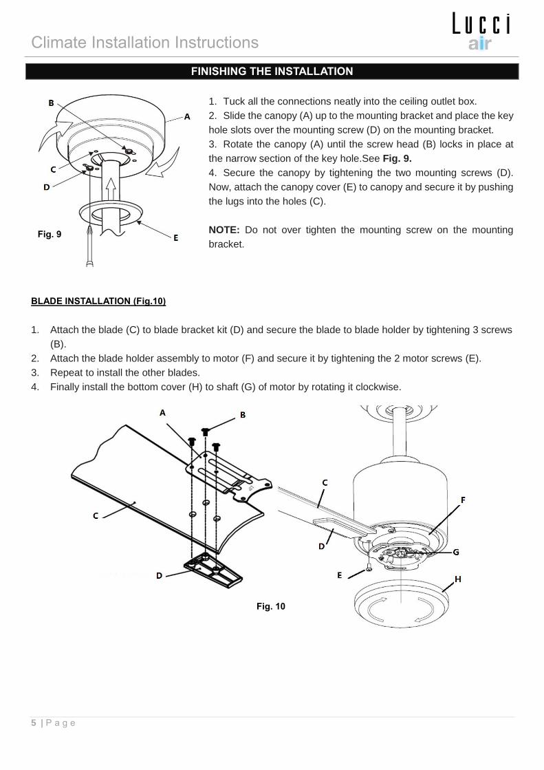
1. Tuck all the connections neatly into the ceiling outlet box.
2. Slide the canopy (A) up to the mounting bracket and place the key
hole slots over the mounting screw (D) on the mounting bracket.
3. Rotate the canopy (A) until the screw head (B) locks in place at
the narrow section of the key hole.See Fig. 9.
4. Secure the canopy by tightening the two mounting screws (D).
Now, attach the canopy cover (E) to canopy and secure it by pushing
the lugs into the holes (C).
NOTE: Do not over tighten the mounting screw on the mounting
bracket.
BLADE INSTALLATION (Fig.10)
1. Attach the blade (C) to blade bracket kit (D) and secure the blade to blade holder by tightening 3 screws
(B).
2. Attach the blade holder assembly to motor (F) and secure it by tightening the 2 motor screws (E).
3. Repeat to install the other blades.
4. Finally install the bottom cover (H) to shaft (G) of motor by rotating it clockwise.
Fig. 9
Fig. 10
Climate Installation Instructions
6 | P a g e
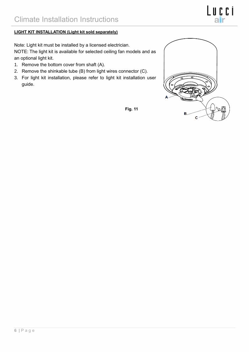
LIGHT KIT INSTALLATION (Light kit sold separately)
Note: Light kit must be installed by a licensed electrician.
NOTE: The light kit is available for selected ceiling fan models and as
an optional light kit.
1. Remove the bottom cover from shaft (A).
2. Remove the shinkable tube (B) from light wires connector (C).
3. For light kit installation, please refer to light kit installation user
guide.
Fig. 11
Climate Installation Instructions
7 | P a g e
USING YOUR CEILING FAN
Pairing Transmitter and Receiver – when 2 or more DC ceiling fans are installed in one location
When two or more fans are located near each other, you may want to have the receiver/transmitter for each
fan set to a different code, so that the operation of one fan does not affect the operation of the other fan/s.
The DIP switches for the transmitter (remote hand piece) are located in the battery compartment of the
transmitter. Configuring the DIP switches will allow a unique transmission code assigned to each fan ceiling.
NOTE: Ensure that you have installed a single pole disconnection switch in the fixed wiring for each fan.
NOTE: Ensure power to the receiver is ON prior to pairing the transmitter with the receiver.
Transmitter / Receiver pairing for Ceiling fan 1:
⚫ Turn OFF the mains supply to the receivers of both ceiling fans 1 and 2.
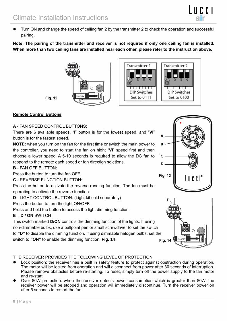
⚫ Install the 12V DC battery in the compartment. Please make sure the polarity of the battery is correct.
Fig.12
⚫ Change the position of the DIP switches in the transmitter 1, so that it will be different to transmitter 2.
⚫ Turn on the power to receiver 1. Keep the power OFF to receiver 2. (Each ceiling fan must have its own
isolation switch, so that only the ceiling fan that needs to be paired with the transmitter will be ON).
⚫ Press and hold the “SET” button of transmitter 1 for 6 seconds within 60 seconds of switching the power
ON to the receiver of ceiling fan 1.
While pairing the DC fan remote and receiver is in process, the fan will automatically start to rotate in the
counterclockwise direction and on the highest RPM for 3 minutes. When counterclockwise rotation has
finished, the fan will automatically reverse to clockwise direction to the highest RPM for 3 minutes. Fan
will shut off when the paring process has finished. During the paring process, the remote is non-functional.
⚫ Turn ON and change the speed of the ceiling fan 1 by the transmitter 1 to check the operation and
successful paring.
Transmitter / Receiver paring for Ceiling fan 2:
⚫ Turn off the mains supply to the receivers of both ceiling fans 1 and 2.
⚫ Install the 12V DC battery in the compartment. Please make sure the polarity of the battery is correct.
Fig.12
⚫ Change the position of the DIP switches in the transmitter 2, so that it will be different to transmitter 1.
⚫ Turn on the power to receiver 2. Keep the power OFF to receiver 1. (Each ceiling fan must have its own
isolation switch, so that only the ceiling fan that needs to be paired with the transmitter will be ON).
⚫ Press and hold the “SET” button of transmitter 2 for 6 seconds within 60 seconds of switching the power
ON to the receiver of ceiling fan 2.
While pairing the DC fan remote and receiver is in process, the fan will automatically start to rotate in the
counterclockwise direction and on the highest RPM for 3 minutes. When counterclockwise rotation has
finished, the fan will automatically reverse to clockwise direction again to the highest RPM for 3 minutes.
Fan will shut off when the paring process has finished. During the paring process, the remote is non-
functional.
Climate Installation Instructions
8 | P a g e
⚫ Turn ON and change the speed of ceiling fan 2 by the transmitter 2 to check the operation and successful
pairing.
Note: The pairing of the transmitter and receiver is not required if only one ceiling fan is installed.
When more than two ceiling fans are installed near each other, please refer to the instruction above.
Remote Control Buttons
A - FAN SPEED CONTROL BUTTONS:
There are 6 available speeds. “I” button is for the lowest speed, and “VI”
button is for the fastest speed.
NOTE: when you turn on the fan for the first time or switch the main power to
the controller, you need to start the fan on hight “VI” speed first and then
choose a lower speed. A 5-10 seconds is required to allow the DC fan to
respond to the remote each speed or fan direction seletions.
B - FAN OFF BUTTON:
Press the button to turn the fan OFF.
C - REVERSE FUNCTION BUTTON:
Press the button to activate the reverse running function. The fan must be
operating to activate the reverse function.
D - LIGHT CONTROL BUTTON: (Light kit sold separately)
Press the button to turn the light ON/OFF.
Press and hold the button to access the light dimming function.
E – D / ON SWITCH
This switch marked D/ON controls the dimming function of the lights. If using
non-dimmable bulbs, use a ballpoint pen or small screwdriver to set the switch
to “D” to disable the dimming function. If using dimmable halogen bulbs, set the
switch to “ON” to enable the dimming function. Fig. 14
THE RECEIVER PROVIDES THE FOLLOWING LEVEL OF PROTECTION:
⚫ Lock position: the receiver has a built in safety feature to protect against obstruction during operation. The motor will be locked from operation and will disconnect from power after 30 seconds of interruption. Please remove obstacles before re-starting. To reset, simply turn off the power supply to the fan motor and re-start.
⚫ Over 80W protection: when the receiver detects power consumption which is greater than 80W, the receiver power will be stopped and operation will immediately discontinue. Turn the receiver power on after 5 seconds to restart the fan.
Fig. 12
Fig. 13
Fig. 14
Climate Installation Instructions
9 | P a g e
REPAIRING THE FAN RECEIVER & REMOTE PAIRING
Should the remote and receiver lose control after installation or during use, the pairing of the remote
and the receiver must be repaired. Below are the operating symptoms and method to repair the pairing
of the DC ceiling fan remote and receiver.
Issues:
⚫ Loss of control - Fan is only running at high speed after installation
⚫ Loss of control - No reverse function after installation
⚫ Loss of control - Remote cannot communicate with receiver
Solution:
A. Switch OFF the main power to ceiling fan for 30 seconds.
B. Press and hold the “SET” button on transmitter for 6 seconds within 60 seconds of switching the power
ON to the receiver of the ceiling fan.
While pairing the DC fan remote and receiver is in process, the fan will automatically start to rotate in the
counterclockwise direction and on the highest RPM for 3 minutes. When counterclockwise rotation has
finished, the fan will automatically reverse to clockwise direction again to the highest RPM for 3 minutes.
Fan will shut off when the paring process has finished. During the paring process, the remote is non-
functional.
C. Turn ON and change the speed of the ceiling fan via the transmitter to check the operation and successful
paring.
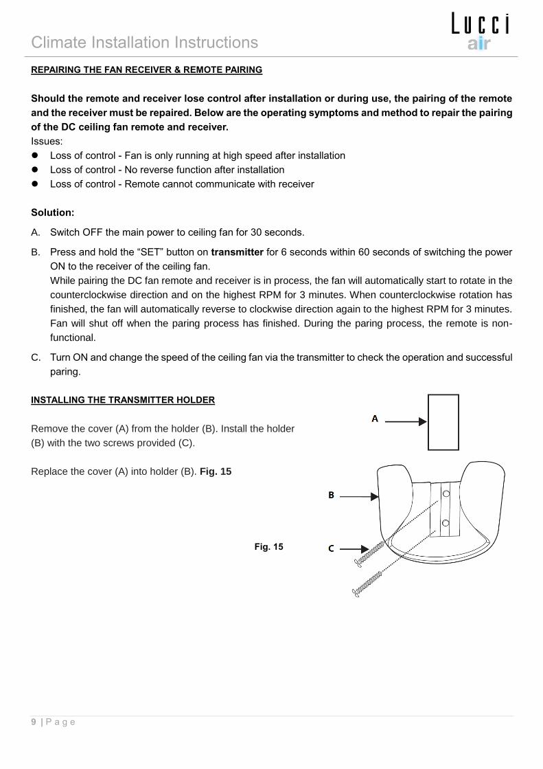
INSTALLING THE TRANSMITTER HOLDER
Remove the cover (A) from the holder (B). Install the holder
(B) with the two screws provided (C).
Replace the cover (A) into holder (B). Fig. 15
Fig. 15
Climate Installation Instructions
10 | P a g e
AFTER INSTALLATION
WOBBLE:
NOTE: ceiling fans tend to move during operation due to the fact that they are mounted on a rubber grommet.
If the fan was mounted rigidly to the ceiling it would cause excessive vibration. Movement of a few centimetres
is quite acceptable and DOES NOT suggest any problem.
TO REDUCE THE FAN WOBBLE: Please check that all screws which fix the mounting bracket and down rod
are secure.
BALANCING KIT: A balancing kit is provided to balance the ceiling fan on initial installation. Please refer to
the instruction on how to use the balancing kit. The balancing kit can be used to assist re-balancing should
the ceiling fan become un-balanced again. Store your balancing kit away after installation for future use if
required.
NOISE:
When it is quiet (especially at night) you may hear occasional small noises. Slight power fluctuations and
frequency signals superimposed in the electricity for off-peak hot water control, may cause a change in fan
motor noise. This is normal. Please allow a 24-hour “breaking-in” period, most noises associated with a new
fan disappear during this time. All electric motors are audible to some extent. Please note that this is not a
product fault, and as such is not coverd under warranty.
CARE AND CLEANING:
⚫ Periodic cleaning of your ceiling fan is the only maintenance required. Use a soft brush or lint free cloth
to avoid scratching the paint finish. Please turn off electricity power when you do so.
⚫ Do not use water when cleaning your ceiling fan. It could damage the motor or the blades and create the
possibility of an electrical shock.
⚫ The motor has a permanently lubricated ball bearing so there is no need to oil.
NOTE: Always turn OFF the power at the mains switch before attempting to clean your fan.
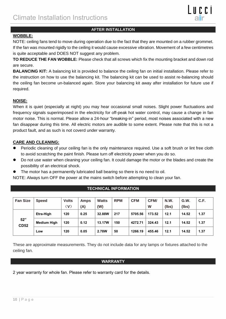
TECHNICAL INFORMATION
Fan Size Speed Volts
(V)
Amps
(A)
Watts
(W)
RPM CFM CFM/
W
N.W.
(lbs)
G.W.
(lbs)
C.F.
52”
CD52
Etra-High 120 0.25 32.88W 217 5705.56 173.52 12.1 14.52 1.37
Medium High 120 0.12 13.17W 150 4272.71 324.43 12.1 14.52 1.37
Low 120 0.05 2.78W 50 1266.19 455.46 12.1 14.52 1.37
These are approximate measurements. They do not include data for any lamps or fixtures attached to the
ceiling fan.
WARRANTY
2 year warranty for whole fan. Please refer to warranty card for the details.
Climate Installation Instructions
11 | P a g e