Embed Size (px)
Citation preview
The 3rd International Conference on Design Engineering and Science, ICDES 2014 Pilsen, Czech Republic, September 1-3, 2014
Copyright © 2014, The Organizing Committee of the ICDES 2014
Lubrication State on the Sliding Part of a Multiple Vane Type Compressor
Eita KUREHA *1 and Masayoshi MURAKI*2 *1 Research Center, Research and Development Center, Yanmar Co., Ltd.
1600-4, Umegahara, Maibara-shi, Shiga 521-8511, JAPAN [email protected]
*2 Department of Mechanical Engineering, Shonan Institute of Technology 1-25, Tsujido-nishikaigan 1-chome, Fujisawa-shi, Kanagawa 251-8511, JAPAN
Abstract Excessive wear of sliding part of a multiple vane type compressor after its long-period use in HCFC-22 was reported in some operating conditions. Then, influence of refrigerant gas on wear of sliding material was studied with a test rig. As a result, the wear amount in HCFC-22 was much larger than that in HFC-134a and air because of corrosive wear under the severe conditions. Then, oil film formation on the top of vane was evaluated as the separation degree using the compressor equipped with an electrical insulating circuit. The separation degree decreased with a decrease in oil supply quantity and with an increase in suction pressure. In order to study the influence of suction pressure, the parameters affecting oil film formation were determined by taking into consideration the force balance around vane. The calculated oil film parameter could be obtained. Change in with suction pressure qualitatively showed a good agreement with that of separation degree. Keywords: multiple vane type compressor, refrigerant, lubrication, oil film parameter, suction pressure
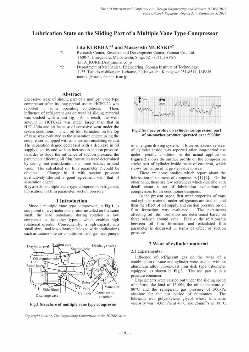
1 Introduction Since a multiple vane type compressor, in Fig.1, is
composed of a cylinder and a rotor installed on the same shaft, the load unbalance during rotation is low compared to the other types,which enables high rotational speeds. Consequently,a high capacity at a small size,and low vibration leads to wide applications such as automobile air conditioners and gas heat pumps
of an engine driving system. However, excessive wear of cylinder inside was reported after long-period use under specific condition in the actual application. Figure 2 shows the surface profile on the compression stroke part of cylinder inside made of cast iron, which shows formation of large steps due to wear.
There are some studies which report about the lubrication phenomena of compressors [1] [2]. On the other hand, there are few references which describe with detail about a set of lubrication evaluations of compressors for air conditioner designers.
In the present paper, first wear properties of vane and cylinder material under refrigerants are studied, and then the effect of oil supply and suction pressure on oil film formation was evaluated. The parameters affecting oil film formation are determined based on force balance around vane. Finally, the relationship between oil film formation and calculated film parameter is discussed in terms of effect of suction pressure.
2 Wear of cylinder material 2.1 Experimental
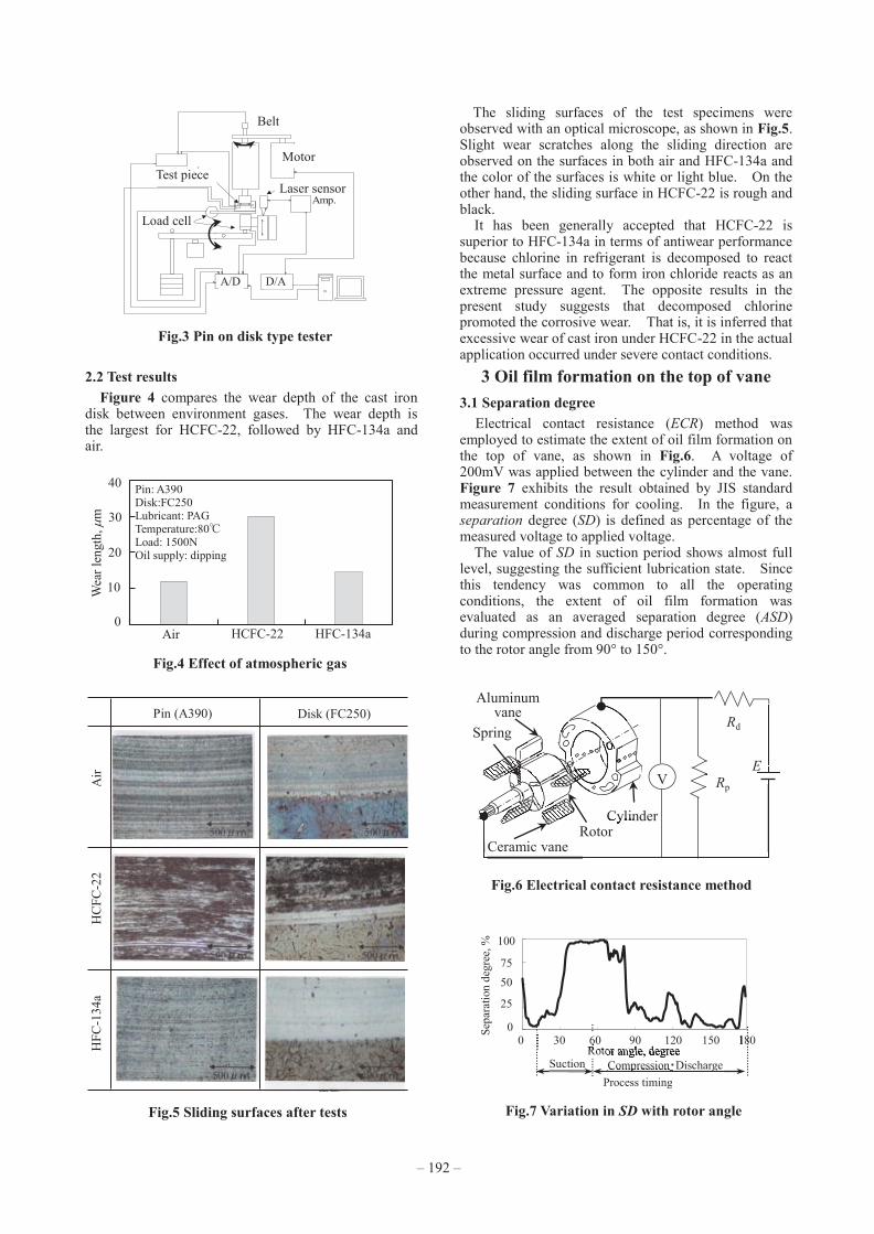
Influence of refrigerant gas on the wear of a combination of vane and cylinder were studied with an aluminum alloy pin-on-cast iron disk type tribometer equipped, as shown in Fig.3. The test part is in a pressure container.
Experiments were carried out under the sliding speed of 0.5m/s, the load of 1500N, the oil temperature of 80°C and the refrigerant gas pressure of 500kPa absolute for the test period of 60minutes. The lubricant was polyalkylene glycol whose kinematic viscosity was 143mm2/s at 40°C and 25mm2/s at 100°C. Fig.1 Structure of multiple vane type compressor
Side Block
Discharge valve
Rotor
CylinderVane
Suction holeDischarge port
Suction holeDischarge port Suction port
Discharge case
Vane-slotCompression
chamber
Oil chamber
Rotor journal
Fig.2 Surface profile on cylinder compression part of on-market product operated over 5000hr
52mm
5m52mm
5m
penetrated disc was small. Because of the higher density, it is concluded that the penetrating MoS2 has sufficient adhesion strength against the stress acted at the interface between the ring and the disc during the experiment. Therefore, it was estimated that the survived MoS2 resulted in the restriction of the titanium transfer to the steel ring was restricted and that the friction properties became stable without seizure occurrence.
Fig. 8 Optical micro image and surface profile of discs
after the experiment (The sliding direction corresponded from top to bottom of the image)
Fig. 9 Optical micro image and surface profile of rings
after the experiment
Summary The surface modification technique based on the
surface plastic deformation process consisted from a micro shot peening and a roller burnishing was proposed and was applied to titanium disc specimen. The resulted surface morphology was dispersed micro dimples filled with dense molybdenum disulfide and was relatively flat. The tribological properties evaluated with a ring on disc type testing apparatus showed that the friction coefficient was lower and stable without seizure. It is estimated that the molybdenum disulfide prevents the titanium transfer.
References [1] Boyer, R. R., An overview on the use of titanium in
the aerospace industry, Materials Science and Engineering: A, Vol. 213, No. 1-2 (1996), pp. 103–114, International Symposium on Metallurgy and Technology of Titanium Alloys.
[2] Croccolo, D., Agostinis, M. D, and Vincenziet, N., Influence of tightening procedures and lubrication conditions on titanium screw joints for lightweight applications, Tribology International, Vol. 55, No. 4, (2012), pp. 68–76.
[3] Abdel-Aal, H.A. Nouari, M., and Mansori, M. E, Influence of thermal conductivity on wear when machining titanium alloys, Tribology International, Vol. 42, No. 2, (2009),pp. 359-372.
[4] Boving, H.J. and Hintermann, H.E., Wear-resistant hard titanium carbide coatings for space applications Tribology International, Vol. 23, No. 2,(1990), pp. 129-133.
[5] Miyoshi, K, et al, Wear behavior of low-cost, lightweight TiC/Ti–6Al–4V composite under fretting: Effectiveness of solid-film lubricant counter-parts, Tribology International, Vol. 41, No. 1, (2008), pp. 24–33.
[6] Martins, R.C., Moura, P. S. and Seabra, J.O., MoS2/Ti low-friction coating for gears, Tribology Inter-national, Vol. 39, No. 12, (2006), pp. 1686-1697.
Received on December 30, 2013 Accepted on February 14, 2014
– 191 –
The 3rd International Conference on Design Engineering and Science, ICDES 2014Pilsen, Czech Republic, August 31 – September 3, 2014
– 190 –
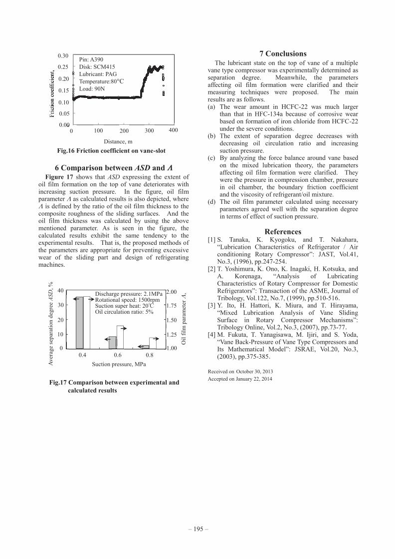
3.2 Effect of oil circulation ratio The oil supply quantity to the top of vane was studied
by adjusting oil circulation ratio OCR, in which OCR was defined as the ratio of circulating oil flow to circulating refrigerant flow.
Figure 8 shows the effect of OCR on ASD. As OCR increases, ASD first increases, and then it tends to level off. This suggests that a sufficient oil film formation can be obtained on the condition of OCR more than 5%. This can be easily understood that an increase in ASD was brought about by increase in oil supply. 3.3 Effect of suction pressure
Next, the effect of suction pressure on ASD was studied under the real field conditions. As will be shown later, ASD deteriorates with increasing suction pressure. This is because change in suction pressure causes change in some parameters affecting oil film formation on the top of vane. Thus, such parameters have to be determined by taking into consideration the force balance around vane.
4 Dynamic model around vane The forces acting on vane are shown in Fig.9. The
original point of rotor angle was defined as the minor axis of cylinder.
In compression period, vane is subject to huge momentum by the differential force (Pcf - Pcr). The momentum is supported by F1 and F2. After vane cross the major axis of cylinder (rotor angle of 90 degree), the oil film on the working point of F1 is formed by the wedge action. In the contact part of vane on the vane slot, it is considered that F1 is supported by oil film force (Fof1) and direct contact force (Fc1). Fof1 was calculated by infinite width theory. Meanwhile, Fc1 was calculated based on the mixed lubrication theory using GT model [3]. Thus, 1F1 is expressed as follow,
oilcb FFF 111 (1)
)()( 111 ofc FFF (2)
where b is the boundary friction coefficient, and Foil is the shear resistance of an oil film.
On the other hand, F2 is assumed to be supported only by direct contact force. Finally, Fn can be obtained based on the force balance along x-direction forces (Pcf, Pcr, Po, 1F1, 2F2). In addition, it is considered that Fn is also supported by oil film reaction force calculated by Martin’s equation and direct contact
force. On the basis of the force balance around the vane, the parameters affecting oil film formation on the top of vane are pressure in compression chamber Pcf and Pcr, pressure in oil chamber Po, the viscosity of refrigerant/oil mixture and the boundary friction coefficient . The viscosity for calculation of oil film thickness was obtained by the theoretical pressure and temperature in the forward compression chamber.
5 Parameters affecting oil film formation
5.1 Pressure in compression chamber Pc Pc influences F1, F2, and , and acts in the opposite
direction of Fn. Therefore, Pc has to be estimated accurately. The compression chamber rotates with rotating rotor, so Pc was measured by installing five pressure sensors in this compressor. Pc over one cycle is obtained by combining five datum of pressure sensors, as shown Fig.10. It is identified that the over-compression is high, and that the pressure until the maximum pressure can be predicted by theoretical adiabatic compression.
Suction pressure: 0.6MPaDischarge pressure: 2.1MPa Rotational speed: 2000rpmSuction super heat: 30℃
Fig.8 Effect of OCR on ASDOil circulate ratio OCR, %
0 10 15 5 0
10
20
Aver
age
sepa
ratio
n de
gree
AS
D, %
30
Fig.9 Dynamical model around vane
P: PressureF: Acting force of vaneV: Velocity: friction coefficient: ViscositySubscriptn: The top of vane
s: The side of vanec: Compression chamberf: Forward arear: Rear area1,2: Point of acting point hmin:Minimum oil film thickness
Pcf
Pcr
Po
F1
F2
1F1
x
2F2
y
PcfFn
Vn
hmin
Fn
Pcr
Vs
Fig.10 Variation in pressure with rotor angle
0.00.51.01.52.02.53.03.5
0 60 120 180
Pres
sure
, MPa
(abs
)
Rotor angle, degree
Sensor① ② ③ ④ ⑤
Theoretical line
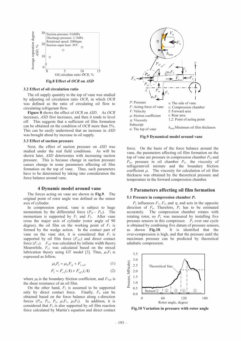
2.2 Test results Figure 4 compares the wear depth of the cast iron
disk between environment gases. The wear depth is the largest for HCFC-22, followed by HFC-134a and air.
The sliding surfaces of the test specimens were observed with an optical microscope, as shown in Fig.5. Slight wear scratches along the sliding direction are observed on the surfaces in both air and HFC-134a and the color of the surfaces is white or light blue. On the other hand, the sliding surface in HCFC-22 is rough and black.
It has been generally accepted that HCFC-22 is superior to HFC-134a in terms of antiwear performance because chlorine in refrigerant is decomposed to react the metal surface and to form iron chloride reacts as an extreme pressure agent. The opposite results in the present study suggests that decomposed chlorine promoted the corrosive wear. That is, it is inferred that excessive wear of cast iron under HCFC-22 in the actual application occurred under severe contact conditions.
3 Oil film formation on the top of vane 3.1 Separation degree
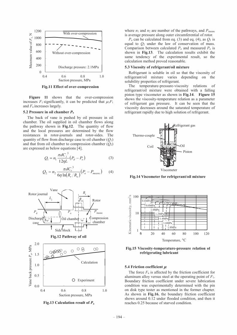
Electrical contact resistance (ECR) method was employed to estimate the extent of oil film formation on the top of vane, as shown in Fig.6. A voltage of 200mV was applied between the cylinder and the vane. Figure 7 exhibits the result obtained by JIS standard measurement conditions for cooling. In the figure, a separation degree (SD) is defined as percentage of the measured voltage to applied voltage.
The value of SD in suction period shows almost full level, suggesting the sufficient lubrication state. Since this tendency was common to all the operating conditions, the extent of oil film formation was evaluated as an averaged separation degree (ASD) during compression and discharge period corresponding to the rotor angle from 90° to 150°.
Fig.3 Pin on disk type tester
Fig.2 Schematic diagram of pin-on disk tester
motor
belt
Amp.
test piece
Load cell
Laser sensor
motor
belt
Amp.
test piece
Load cell
Laser sensorLaser sensorTest piece
Load cell
Belt
Motor
A/D
D/A
Fig.4 Effect of atmospheric gas
Air
Wea
r len
gth,
m
0
10
20
30
40
HCFC-22 HFC-134a
Pin: A390 Disk:FC250 Lubricant: PAG Temperature:80℃ Load: 1500N Oil supply: dipping
Fig.5 Sliding surfaces after tests
Air
HC
FC-2
2H
FC-1
34a
Pin (A390) Disk (FC250)
Fig.6 Electrical contact resistance method
Aluminumvane
Cylinder
Ceramic vane
Spring
CylinderRotor
Rd
V Rp
E
Fig.7 Variation in SD with rotor angle
Rotor angle, degree Suction
Rotor angle, degreeCompression・Discharge CompressionCompression
Process timing
75 50 25
0
100
0 Rotor angle, degree
30 Rotor angle, degree
90 180 180150 Rotor angle, degreeRotor angle, degree
120 Rotor angle, degreeRotor angle, degreeRotor angle, degree60 Se
para
tion
degr
ee, %
– 193 – – 192 –
3.2 Effect of oil circulation ratio The oil supply quantity to the top of vane was studied
by adjusting oil circulation ratio OCR, in which OCR was defined as the ratio of circulating oil flow to circulating refrigerant flow.
Figure 8 shows the effect of OCR on ASD. As OCR increases, ASD first increases, and then it tends to level off. This suggests that a sufficient oil film formation can be obtained on the condition of OCR more than 5%. This can be easily understood that an increase in ASD was brought about by increase in oil supply. 3.3 Effect of suction pressure
Next, the effect of suction pressure on ASD was studied under the real field conditions. As will be shown later, ASD deteriorates with increasing suction pressure. This is because change in suction pressure causes change in some parameters affecting oil film formation on the top of vane. Thus, such parameters have to be determined by taking into consideration the force balance around vane.
4 Dynamic model around vane The forces acting on vane are shown in Fig.9. The
original point of rotor angle was defined as the minor axis of cylinder.
In compression period, vane is subject to huge momentum by the differential force (Pcf - Pcr). The momentum is supported by F1 and F2. After vane cross the major axis of cylinder (rotor angle of 90 degree), the oil film on the working point of F1 is formed by the wedge action. In the contact part of vane on the vane slot, it is considered that F1 is supported by oil film force (Fof1) and direct contact force (Fc1). Fof1 was calculated by infinite width theory. Meanwhile, Fc1 was calculated based on the mixed lubrication theory using GT model [3]. Thus, 1F1 is expressed as follow,
oilcb FFF 111 (1)
)()( 111 ofc FFF (2)
where b is the boundary friction coefficient, and Foil is the shear resistance of an oil film.
On the other hand, F2 is assumed to be supported only by direct contact force. Finally, Fn can be obtained based on the force balance along x-direction forces (Pcf, Pcr, Po, 1F1, 2F2). In addition, it is considered that Fn is also supported by oil film reaction force calculated by Martin’s equation and direct contact
force. On the basis of the force balance around the vane, the parameters affecting oil film formation on the top of vane are pressure in compression chamber Pcf and Pcr, pressure in oil chamber Po, the viscosity of refrigerant/oil mixture and the boundary friction coefficient . The viscosity for calculation of oil film thickness was obtained by the theoretical pressure and temperature in the forward compression chamber.
5 Parameters affecting oil film formation
5.1 Pressure in compression chamber Pc Pc influences F1, F2, and , and acts in the opposite
direction of Fn. Therefore, Pc has to be estimated accurately. The compression chamber rotates with rotating rotor, so Pc was measured by installing five pressure sensors in this compressor. Pc over one cycle is obtained by combining five datum of pressure sensors, as shown Fig.10. It is identified that the over-compression is high, and that the pressure until the maximum pressure can be predicted by theoretical adiabatic compression.
Suction pressure: 0.6MPaDischarge pressure: 2.1MPa Rotational speed: 2000rpmSuction super heat: 30℃
Fig.8 Effect of OCR on ASDOil circulate ratio OCR, %
0 Oil circulate ratio OCR
10 15 Oil circulate ratio
5 00
10
20
Aver
age
sepa
ratio
n de
gree
AS
D, %
30
Fig.9 Dynamical model around vane
P: PressureF: Acting force of vaneV: Velocity: friction coefficient: ViscositySubscriptn: The top of vane
s: The side of vanec: Compression chamberf: Forward arear: Rear area1,2: Point of acting point hmin:Minimum oil film thickness
Pcf
Pcr
Po
F1
F2
1F1
x
2F2
y
PcfFn
Vn
hmin
Fn
Pcfcf
Pcr
Vs
Fig.10 Variation in pressure with rotor angle
0.00.51.01.52.02.53.03.5
0 60 120 180
Pres
sure
, MPa
(abs
)
Rotor angle, degree
Sensor① ② ③ ④ ⑤
Theoretical line
2.2 Test results Figure 4 compares the wear depth of the cast iron
disk between environment gases. The wear depth is the largest for HCFC-22, followed by HFC-134a and air.
The sliding surfaces of the test specimens were observed with an optical microscope, as shown in Fig.5. Slight wear scratches along the sliding direction are observed on the surfaces in both air and HFC-134a and the color of the surfaces is white or light blue. On the other hand, the sliding surface in HCFC-22 is rough and black.
It has been generally accepted that HCFC-22 is superior to HFC-134a in terms of antiwear performance because chlorine in refrigerant is decomposed to react the metal surface and to form iron chloride reacts as an extreme pressure agent. The opposite results in the present study suggests that decomposed chlorine promoted the corrosive wear. That is, it is inferred that excessive wear of cast iron under HCFC-22 in the actual application occurred under severe contact conditions.
3 Oil film formation on the top of vane 3.1 Separation degree
Electrical contact resistance (ECR) method was employed to estimate the extent of oil film formation on the top of vane, as shown in Fig.6. A voltage of 200mV was applied between the cylinder and the vane. Figure 7 exhibits the result obtained by JIS standard measurement conditions for cooling. In the figure, a separation degree (SD) is defined as percentage of the measured voltage to applied voltage.
The value of SD in suction period shows almost full level, suggesting the sufficient lubrication state. Since this tendency was common to all the operating conditions, the extent of oil film formation was evaluated as an averaged separation degree (ASD) during compression and discharge period corresponding to the rotor angle from 90° to 150°.
Fig.3 Pin on disk type tester
Fig.2 Schematic diagram of pin-on disk tester
motor
belt
Amp.
test piece
Load cell
Laser sensor
motor
belt
Amp.
test piece
Load cell
Laser sensorLaser sensorTest piece
Load cell
Belt
Motor
A/D
D/A
Fig.4 Effect of atmospheric gas
Air
Wea
r len
gth,
m
0
10
20
30
40
HCFC-22 HFC-134a
Pin: A390 Disk:FC250 Lubricant: PAG Temperature:80℃ Load: 1500N Oil supply: dipping
Fig.5 Sliding surfaces after tests
Air
HC
FC-2
2H
FC-1
34a
Pin (A390) Disk (FC250)
Fig.6 Electrical contact resistance method
Aluminumvane
Cylinder
Ceramic vane
Spring
Rotor
Rd
V Rp
E
Fig.7 Variation in SD with rotor angle
Rotor angle, degree Suction Compression・Discharge
Process timing
75 50 25
0
100
0 30 90 180 150 120 60 Sepa
ratio
n de
gree
, %
– 193 – – 192 –
6 Comparison between ASD and Figure 17 shows that ASD expressing the extent of
oil film formation on the top of vane deteriorates with increasing suction pressure. In the figure, oil film parameter as calculated results is also depicted, where is defined by the ratio of the oil film thickness to the composite roughness of the sliding surfaces. And the oil film thickness was calculated by using the above mentioned parameter. As is seen in the figure, the calculated results exhibit the same tendency to the experimental results. That is, the proposed methods of the parameters are appropriate for preventing excessive wear of the sliding part and design of refrigerating machines.
7 Conclusions The lubricant state on the top of vane of a multiple
vane type compressor was experimentally determined as separation degree. Meanwhile, the parameters affecting oil film formation were clarified and their measuring techniques were proposed. The main results are as follows. (a) The wear amount in HCFC-22 was much larger
than that in HFC-134a because of corrosive wear based on formation of iron chloride from HCFC-22 under the severe conditions.
(b) The extent of separation degree decreases with decreasing oil circulation ratio and increasing suction pressure.
(c) By analyzing the force balance around vane based on the mixed lubrication theory, the parameters affecting oil film formation were clarified. They were the pressure in compression chamber, pressure in oil chamber, the boundary friction coefficient and the viscosity of refrigerant/oil mixture.
(d) The oil film parameter calculated using necessary parameters agreed well with the separation degree in terms of effect of suction pressure.
References
[1] S. Tanaka, K. Kyogoku, and T. Nakahara, “Lubrication Characteristics of Refrigerator / Air conditioning Rotary Compressor”: JAST, Vol.41, No.3, (1996), pp.247-254.
[2] T. Yoshimura, K. Ono, K. Inagaki, H. Kotsuka, and A. Korenaga, “Analysis of Lubricating Characteristics of Rotary Compressor for Domestic Refrigerators”: Transaction of the ASME, Journal of Tribology, Vol.122, No.7, (1999), pp.510-516.
[3] Y. Ito, H. Hattori, K. Miura, and T. Hirayama, “Mixed Lubrication Analysis of Vane Sliding Surface in Rotary Compressor Mechanisms”: Tribology Online, Vol.2, No.3, (2007), pp.73-77.
[4] M. Fukuta, T. Yanagisawa, M. Ijiri, and S. Yoda, “Vane Back-Pressure of Vane Type Compressors and Its Mathematical Model”: JSRAE, Vol.20, No.3, (2003), pp.375-385.
Received on October 30, 2013 Accepted on January 22, 2014
Fig.16 Friction coefficient on vane-slotDistance, m
Pin: A390Disk: SCM415Lubricant: PAGTemperature:80°CLoad: 90N
Fric
tion
coef
ficie
nt,
0.00
0.10
0.20
0.15
0.05
0.30
0.25
0 200 400300100
Fig.17 Comparison between experimental and calculated results
Suction pressure, MPa
1.00 0.4
Aver
age
sepa
ratio
n de
gree
ASD
, %
Oil
film
par
amet
er
,
0
10
20
30
40
1.25
1.50
1.75
2.00
0.6 0.8
Discharge pressure: 2.1MPa Rotational speed: 1500rpm Suction super heat: 20℃ Oil circulation ratio: 5%
Figure 11 shows that the over-compression increases F1 significantly, it can be predicted that 1F1 and Fn increases largely. 5.2 Pressure in oil chamber Po
The back of vane is pushed by oil pressure in oil chamber. The oil supplied in oil chamber flows along the pathway shown in Fig.12. The quantity of flow and the local pressures are determined by the flow resistances in rotor-journals and rotor-sides. The quantity of flow from discharge case to oil chamber (Q1) and that from oil chamber to compression chamber (Q2) are expressed as below equations [4].
odj PPL
CdnQ
12
3
11 (3)
meancoor
r PPRR
dCnQ ln6
3
22 (4)
where n1 and n2 are number of the pathways, and Pmeanc is average pressure along outer circumferential of rotor.
Po can be calculated from eq. (3) and eq. (4), as Q1 is equal to Q2 under the law of conservation of mass. Comparison between calculated Po and measured Po is shown in Fig.13. The calculation results exhibit the same tendency of the experimental result, so the calculation method proved reasonable. 5.3 Viscosity of refrigerant/oil mixture Refrigerant is soluble in oil so that the viscosity of refrigerant/oil mixture varies depending on the solubility properties of refrigerant.
The temperature-pressure-viscosity relations of refrigerant/oil mixture were obtained with a falling piston type viscometer as shown in Fig.14. Figure 15 shows the viscosity-temperature relation as a parameter of refrigerant gas pressure. It can be seen that the viscosity decreases around the saturated temperature of refrigerant rapidly due to high solution of refrigerant.
5.4 Friction coefficientThe force Fn is affected by the friction coefficient for
aluminum alloy versus steel at the operating point of F1. Boundary friction coefficient under severe lubrication condition was experimentally determined with the pin on disk type tester as mentioned in the former chapter. As shown in Fig.16, the boundary friction coefficient shows around 0.12 under flooded condition, and then it reaches 0.25 because of starved condition.
Fig.11 Effect of over-compression
0
200
400
600
800
1000
1200
0.4 0.6 0.8 1.0
Max
mum
val
ue o
f F1,
N
Saction pressure, MPa
With over-compression
Without over-compression
Discharge pressure: 2.1MPa
Fig.12 Pathway of oil
Pd
Compressionchamber
Po Pmeanc
Dischargecase
Oil chamberCj
Lj Ro
Rr
Cr
Vane
Rotor
Rotor journal
Side block
Fig.13 Calculation result of Po
0.0
0.5
1.0
1.5
2.0
0.4 0.6 0.8 1.0
Vane
bac
k pr
essu
re P
o, M
Pa
Saction pressure, MPa
Calculation
○ Experiment
Fig.14 Viscometer for refrigerant/oil mixture
PistonCoil
Thermo-couple
Refrigerant gas
Oil
Viscometer
Refrigerant gas
Fig.15 Viscosity-temperature-pressure relation of refrigerating lubricant
0 20 40 60 80 100 12001
10
1000.6MPa
0.8MPa1.0MPa
1.2MPa
1.8MPa
1.4MPa1.6MPa
Kin
emat
icvi
scos
ity, m
m2 /s
Temperature, °C
– 195 – – 194 –
6 Comparison between ASD and Figure 17 shows that ASD expressing the extent of
oil film formation on the top of vane deteriorates with increasing suction pressure. In the figure, oil film parameter as calculated results is also depicted, where is defined by the ratio of the oil film thickness to the composite roughness of the sliding surfaces. And the oil film thickness was calculated by using the above mentioned parameter. As is seen in the figure, the calculated results exhibit the same tendency to the experimental results. That is, the proposed methods of the parameters are appropriate for preventing excessive wear of the sliding part and design of refrigerating machines.
7 Conclusions The lubricant state on the top of vane of a multiple
vane type compressor was experimentally determined as separation degree. Meanwhile, the parameters affecting oil film formation were clarified and their measuring techniques were proposed. The main results are as follows. (a) The wear amount in HCFC-22 was much larger
than that in HFC-134a because of corrosive wear based on formation of iron chloride from HCFC-22 under the severe conditions.
(b) The extent of separation degree decreases with decreasing oil circulation ratio and increasing suction pressure.
(c) By analyzing the force balance around vane based on the mixed lubrication theory, the parameters affecting oil film formation were clarified. They were the pressure in compression chamber, pressure in oil chamber, the boundary friction coefficient and the viscosity of refrigerant/oil mixture.
(d) The oil film parameter calculated using necessary parameters agreed well with the separation degree in terms of effect of suction pressure.
References
[1] S. Tanaka, K. Kyogoku, and T. Nakahara, “Lubrication Characteristics of Refrigerator / Air conditioning Rotary Compressor”: JAST, Vol.41, No.3, (1996), pp.247-254.
[2] T. Yoshimura, K. Ono, K. Inagaki, H. Kotsuka, and A. Korenaga, “Analysis of Lubricating Characteristics of Rotary Compressor for Domestic Refrigerators”: Transaction of the ASME, Journal of Tribology, Vol.122, No.7, (1999), pp.510-516.
[3] Y. Ito, H. Hattori, K. Miura, and T. Hirayama, “Mixed Lubrication Analysis of Vane Sliding Surface in Rotary Compressor Mechanisms”: Tribology Online, Vol.2, No.3, (2007), pp.73-77.
[4] M. Fukuta, T. Yanagisawa, M. Ijiri, and S. Yoda, “Vane Back-Pressure of Vane Type Compressors and Its Mathematical Model”: JSRAE, Vol.20, No.3, (2003), pp.375-385.
Received on October 30, 2013 Accepted on January 22, 2014
Fig.16 Friction coefficient on vane-slotDistance, m
Pin: A390Disk: SCM415Lubricant: PAGTemperature:80°CLoad: 90N
Fric
tion
coef
ficie
nt,
0.00
Fric
tion
coef
ficie
nt,
0.10
Fric
tion
coef
ficie
nt,
0.20
Fric
tion
coef
ficie
nt,
0.15
Fric
tion
coef
ficie
nt,
0.05
0.30Fr
ictio
n co
effic
ient
, 0.25
0.000 200 400300100
Fig.17 Comparison between experimental and calculated results
Suction pressure, MPa
1.00 0.4
Aver
age
sepa
ratio
n de
gree
ASD
, %
Oil
film
par
amet
er
,
0
10
20
30
40
1.25
1.50
1.75
2.00
0.6 0.8
Discharge pressure: 2.1MPa Rotational speed: 1500rpm Suction super heat: 20℃ Oil circulation ratio: 5%
Figure 11 shows that the over-compression increases F1 significantly, it can be predicted that 1F1 and Fn increases largely. 5.2 Pressure in oil chamber Po
The back of vane is pushed by oil pressure in oil chamber. The oil supplied in oil chamber flows along the pathway shown in Fig.12. The quantity of flow and the local pressures are determined by the flow resistances in rotor-journals and rotor-sides. The quantity of flow from discharge case to oil chamber (Q1) and that from oil chamber to compression chamber (Q2) are expressed as below equations [4].
odj PPL
CdnQ
12
3
11 (3)
meancoor
r PPRR
dCnQ ln6
3
22 (4)
where n1 and n2 are number of the pathways, and Pmeanc is average pressure along outer circumferential of rotor.
Po can be calculated from eq. (3) and eq. (4), as Q1 is equal to Q2 under the law of conservation of mass. Comparison between calculated Po and measured Po is shown in Fig.13. The calculation results exhibit the same tendency of the experimental result, so the calculation method proved reasonable. 5.3 Viscosity of refrigerant/oil mixture Refrigerant is soluble in oil so that the viscosity of refrigerant/oil mixture varies depending on the solubility properties of refrigerant.
The temperature-pressure-viscosity relations of refrigerant/oil mixture were obtained with a falling piston type viscometer as shown in Fig.14. Figure 15 shows the viscosity-temperature relation as a parameter of refrigerant gas pressure. It can be seen that the viscosity decreases around the saturated temperature of refrigerant rapidly due to high solution of refrigerant.
5.4 Friction coefficientThe force Fn is affected by the friction coefficient for
aluminum alloy versus steel at the operating point of F1. Boundary friction coefficient under severe lubrication condition was experimentally determined with the pin on disk type tester as mentioned in the former chapter. As shown in Fig.16, the boundary friction coefficient shows around 0.12 under flooded condition, and then it reaches 0.25 because of starved condition.
Fig.11 Effect of over-compression
0
200
400
600
800
1000
1200
0.4 0.6 0.8 1.0
Max
mum
val
ue o
f F1,
N
Saction pressure, MPa
With over-compression
Without over-compression
Discharge pressure: 2.1MPa
Fig.12 Pathway of oil
Pd
Compressionchamber
Po Pmeanc
Dischargecase
Oil chamberCj
Lj Ro
Rr
Cr
Vane
Rotor
Rotor journal
Side block
Fig.13 Calculation result of Po
0.0
0.5
1.0
1.5
2.0
0.4 0.6 0.8 1.0
Vane
bac
k pr
essu
re P
o, M
Pa
Saction pressure, MPa
Calculation
○ Experiment
Fig.14 Viscometer for refrigerant/oil mixture
PistonCoil
Thermo-couple
Refrigerant gas
Oil
Viscometer
Fig.15 Viscosity-temperature-pressure relation of refrigerating lubricant
0 20 40 60 80 100 1201
10
1000.6MPa
0.8MPa1.0MPa
1.2MPa
1.8MPa
1.4MPa1.6MPa
Kin
emat
icvi
scos
ity, m
m2 /s
Temperature, °C
– 195 – – 194 –