Embed Size (px)
Citation preview
LICENTIATE T H E S I S
Department of Engineering Sciences and Mathematics Division of Machine Elements
Lubrication mechanism of Hydrocarbon-Mimicking Ionic Liquids
ISSN 1402-1757ISBN 978-91-7583-953-0 (print)ISBN 978-91-7583-954-7 (pdf)
Luleå University of Technology 2017
Erik N
yberg Lubrication mechanism
of Hydrocarbon-M
imicking Ionic Liquids Erik Nyberg
Machine Elements

Lubrication mechanism of
Hydrocarbon-Mimicking Ionic Liquids
Erik Nyberg
Luleå University of TechnologyDepartment of Engineering Sciences and Mathematics
Division of Machine Elements

Printed by Luleå University of Technology, Graphic Production 2017
ISSN 1402-1757 ISBN 978-91-7583-953-0 (print)ISBN 978-91-7583-954-7 (pdf)
Luleå 2017
www.ltu.se
i
PREFACE
This licentiate thesis is based on work within a PhD project that was
initiated in September 2015 at the Division of Machine Elements at Luleå
University of Technology.
The work has been financially supported by the “Austrian COMET-
Program” in the frame of K2 XTribology (project no. 849109). The Taiho
Kogyo Tribology Research Foundation (TTRF) also provided funding
through the 2016 15B07 grant. The Graduate School of Space Technology at
Luleå University of Technology is also acknowledged for financial support.
I would like to thank all my colleagues at the division of Machine Elements
for good company and valuable discussions. Some of my current colleagues
are former teachers of mine, and I am thankful for being introduced by them
to the interesting topic of tribology. I am also thankful to the Graduate School
of Space Technology for introducing me to space science and technology, and
for providing a platform for continued studies in this field.
I want to thank my supervisors and project partners for initiating this
research and for valuable discussions along the way so far; Ichiro Minami,
Mattias Grahn, and Javier Martin-Torres, together with our project partners
at AC2T and IK4-Tekniker. A special thank you to my main supervisor Ichiro
Minami for excellent organization, encouragement, and cooperation during
this work.
I would also like to thank my family, friends and teammates for providing
different points of view and for saving me from drifting into space at times.
A special thanks goes to my good friend Jonny, who I am lucky to also be
sharing office with.
Most importantly, thank you Susanne & N for being my source of energy
and inspiration.
Luleå, October 2017
Erik Nyberg
ii
ABSTRACT Lubrication is critical in order to achieve high efficiency and reliability of
machine elements such as gears, bearings, and other moving mechanical
assemblies (MMA). In space applications, tribological properties of
lubricants are quickly growing more important. Traditional space systems
such as satellites imply MMA such as gyroscopes, antenna pointing
mechanisms, and solar array drives. These MMA operate in high vacuum
(<10-5 Pa) under lightly loaded conditions. Modern space missions on the
other hand, such as remotely operated vehicles used for in-situ Mars
exploration relies on different types of MMA. In these robotic systems,
electromechanical actuators are being used extensively to provide controlled
motion. Gears and bearings in these actuators operate in an atmosphere
mainly consisting of CO2 at ~10+3 Pa under heavily loaded contact conditions.
In these conditions, the tribosystem is likely to operate in the boundary
lubricated regime, with consequent risk of high friction and wear.
High molecular weight fluids have significant heritage in space because of
their low vapor pressure. They are currently employed as lubricants in a wide
range of space applications, as they meet high demands on resistance to
vacuum outgassing. Unfortunately, the large molecules are susceptible to
degradation under heavy load.
Ionic liquids (ILs) on the other hand, are synthetic fluids that consist
entirely of ion pairs with opposing charge. The resulting ion bonds enable
inherently low vapor pressure of the fluid without the need for a high
molecular weight. For this reason ILs have been advocated as potential
lubricants for space applications, but so far compatibility issues have
hampered their use as lubricants. Countless IL variations are possible, and
solutions are thus likely to exist. Constituent ions can be designed
individually and combined in various configurations. However, the
fundamental understanding of the lubricating mechanism of ionic liquids is
still incomplete, and consequently the optimum molecular structure for IL
lubricants remain unknown.
In this thesis, a stepwise approach to molecular design of IL lubricants is
described, and the resulting hydrocarbon-mimicking ionic liquids are
evaluated in tribological experiments. In this thesis, the experiments focus on
tribological performance, using steel-steel tribopairs in air environment under
boundary lubrication (Paper I). Boundary film formation under a range of
contact pressures and temperatures, is analyzed after tribotesting by optical
profilometry, scanning electron microscopy (SEM), and energy dispersive X-
iii
ray spectroscopy (EDS) in Paper II. The analysis reveal formation of a highly
effective boundary film based on silicate, that can be further enhanced by
amine additives. This thesis demonstrates the feasibility of improving
tribological performance of ionic liquids by molecular design.
iv
TABLE OF CONTENTS
1 INTRODUCTION 3
1.1 BACKGROUND AND MOTIVATION OF RESEARCH 3
1.1.1 RESEARCH OBJECTIVES 4
2 TRIBOLOGY 6
2.1 HISTORICAL EVENTS TOWARDS TRIBOLOGY 7
2.2 DEFINITIONS 8
2.2.1 DEFINITION OF TRIBOSYSTEM 8
2.2.2 DEFINITION OF FRICTION 9
2.2.3 DEFINITION OF WEAR 10
2.3 LUBRICATION CONCEPTS 10
2.3.1 LUBRICATION REGIMES 10
2.3.2 BOUNDARY LUBRICATION 13
3 LUBRICATION IN SPACE ENVIRONMENT 16
3.1 LUBRICANTS USED IN SPACE APPLICATIONS 17
3.1.1 NOTE ON SOLID LUBRICANTS 17
3.1.2 LIQUID LUBRICANTS 17
3.2 CONSIDERATIONS OF MARS APPLICATION 18
4 IONIC LIQUID LUBRICANTS 20
4.1 BACKGROUND OF IONIC LIQUIDS 20
4.2 IONIC LIQUIDS IN TRIBOLOGY 21
4.3 POTENTIAL OF DESIGNING IL AS LUBRICANT 23
5 MATERIALS AND METHODS 25
5.1 DESIGN OF HYDROCARBON-MIMICKING ILS 25
v
5.1.1 CATION CONSIDERATIONS 25
5.1.2 ANION CONSIDERATIONS 26
5.2 EXPERIMENTAL PROCEDURE 27
5.2.1 LUBRICANT DATA 27
5.2.2 TRIBOTESTING 28
5.2.3 SURFACE ANALYSIS 28
6 RESULTS AND DISCUSSION 30
6.1 PERFORMANCE OF NEAT P-SISO 30
6.2 EFFECTIVENESS OF ADDITIVES IN P-SISO 34
6.3 ANALYSIS OF BOUNDARY FILM 36
6.3.1 PRIMARY BOUNDARY FILM OF P-SISO 37
6.3.2 TRANSITION TO SECONDARY BOUNDARY FILM 39
6.3.3 BOUNDARY FILM GROWTH ENHANCED BY AMINE ADDITIVE 40
7 SUMMARY AND OUTLOOK 42
8 REFERENCES 43
APPENDED PAPERS 54

1
APPENDED PAPERS
PAPER I
E. Nyberg, C. Y. Respatiningsih, and I. Minami
“Molecular design of advanced lubricant base fluids: hydrocarbon-
mimicking ionic liquids,”
RSC Advances, vol. 7, no. 11, pp. 6364–6373, 2017.
Content: This study reports the molecular design and tribological
evaluation of hydrocarbon-mimicking room-temperature ionic liquids
(RTILs), abbreviated as P-SiSO. We strived to combine useful properties
inherent to ionic liquids with a hydrocarbon-mimicking molecular
design. The aim was improved tribological performance while retaining
the inherent benefits of ionic interaction in RTILs.
Author contribution: E.N. performed most of the experiments and
analysis, and wrote the manuscript.
PAPER II
E. Nyberg, J. Mouzon, M. Grahn, and I. Minami
“Formation of Boundary Film from Ionic Liquids Enhanced by
Additives,”
Applied Sciences, vol. 7, no. 5, p. 433, 2017.
Content: This article reports the tribological evaluation supported by
surface analysis of conventional additives in a novel hydrocarbon-
mimicking ionic liquid (P-SiSO). The boundary film formation of these
novel fluids is analyzed. The results reveal the formation of an effective
boundary film composed of mainly Si and O, that could be further
enhanced by an amine additive.
Author contribution: E.N. performed most of the experiments and
analysis, and wrote the manuscript.
2
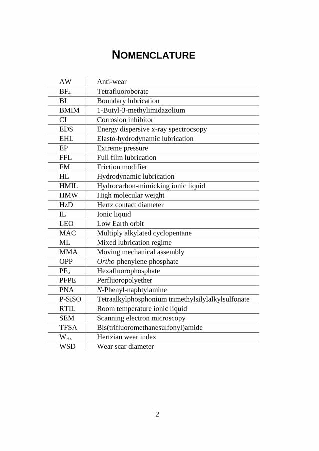
NOMENCLATURE
AW Anti-wear
BF4 Tetrafluoroborate
BL Boundary lubrication
BMIM 1-Butyl-3-methylimidazolium
CI Corrosion inhibitor
EDS Energy dispersive x-ray spectrocsopy
EHL Elasto-hydrodynamic lubrication
EP Extreme pressure
FFL Full film lubrication
FM Friction modifier
HL Hydrodynamic lubrication
HMIL Hydrocarbon-mimicking ionic liquid
HMW High molecular weight
HzD Hertz contact diameter
IL Ionic liquid
LEO Low Earth orbit
MAC Multiply alkylated cyclopentane
ML Mixed lubrication regime
MMA Moving mechanical assembly
OPP Ortho-phenylene phosphate
PF6 Hexafluorophosphate
PFPE Perfluoropolyether
PNA N-Phenyl-naphtylamine
P-SiSO Tetraalkylphosphonium trimethylsilylalkylsulfonate
RTIL Room temperature ionic liquid
SEM Scanning electron microscopy
TFSA Bis(trifluoromethanesulfonyl)amide
WHz Hertzian wear index
WSD Wear scar diameter
3
1 INTRODUCTION
1.1 BACKGROUND AND MOTIVATION OF RESEARCH Lubrication is critical in order to achieve high efficiency and
reliability of machine elements such as gears, bearings, and other moving
mechanical assemblies (MMA). To reduce friction and wear, the ideal
state of lubrication is usually the full film lubricated (FFL) regime where
a thin film of liquid lubricant completely separates the moving surfaces
by hydrodynamic pressure (possibly combined with elastic material
deformation) so that direct contact between the solid surfaces is avoided.
In FFL, wear is minimized by eliminating the main wear modes of
abrasion and adhesion, while friction is limited to the shearing of the
viscous fluid film [3].
Unfortunately, there are many instances where it is not practically
feasible to operate in the FFL regime; for example when the tribological
system is subjected to start-and-stop, high contact pressures, or lubricant
starvation. Harsh operating conditions like these force the tribosystem to
shift lubrication regime from FFL towards the boundary lubrication (BL)
regime [4]. In BL, the normal load is mainly carried by the solid surface
asperities instead of the liquid phase, and therefore specific measures are
required in order to avoid catastrophic levels of friction and wear. Many
decades of empirical research has developed additives that significantly
improve lubricant performance in BL by chemically reacting with the
lubricated surfaces [5]–[7]. In this manner, the surface can be (in-situ)
coated with a protective boundary film. The mechanism of how
boundary films function is still far from clarified; it is a complex
interaction that requires consideration of both mechanical and chemical
effects in highly dynamic conditions. Since the fundamental
understanding of boundary films is lacking, problems arise for
unconventional tribosystems that operate in BL.
As a consequence of new trends in the space industry following the
increased focus on in-situ planetary exploration [8]–[13], requirements
on lubricants are evolving. Traditionally, space tribology implies MMAs
operating on satellites in high vacuum, at relatively steady conditions,
and in absence of gravitational load [14]–[17]. In contrast, modern space
exploration missions, especially surface missions on Mars, rely heavily
on robotic equipment where electromechanical actuators are being used
4
extensively [18]–[23]. Gears and bearings in these actuators must operate
with small amounts of lubricant in highly dynamic contact conditions,
which increases the risk of operation in the BL regime. The lubricants
qualified for use in space however, are generally optimized for low vapor
pressure in order to meet requirements on outgassing in high vacuum
[24]. These synthetic fluids have significantly different chemical
structures compared to traditional lubricants used for similar machinery
on earth, thus excluding the use of conventional additives used to
improve BL performance.
Ionic liquids (ILs) have evolved from molten salts to become
potentially game changing synthetic fluids in many technical
applications; one potential use is as lubricants in demanding applications,
where the non-volatile and highly stable nature of ionic liquids promotes
use in extreme environments. The ILs consist entirely of ion pairs with
opposing charge. Because of the strong ion bonds in these fluids, they
hold inherently low vapor pressure, and for this reason ILs have been
advocated as potential lubricants for space applications since their
inception in tribology in 2001 [25].
After more than a decade of intensive research on ILs, it has been
established that they readily form boundary films that are beneficial to
performance in BL [26]–[28]. This reactivity however is a double-edged
sword, if the reactivity towards the lubricated surface is too high, it can
cause corrosive wear instead of generating a protective boundary film.
Early ILs have been largely based on fluorine anions. While the strong
electronegativity of fluorine is associated with non-measurable vapor
pressure, and excellent thermal stability, it is also responsible for
excessive reactivity in tribological conditions. Also, as with many
synthetic fluids, ILs have generally displayed low compatibility with
existing additive technology due to significantly different chemical
structures compared to the hydrocarbons base oils that additives have
been designed for.
1.1.1 Research objectives Although the research interest regarding ionic liquids as lubricants has
been increasing sharply over the last 15 years, the fundamental
understanding of the lubricating mechanism of ionic liquids is still
incomplete. Consequently, the optimum molecular structure remains
unknown. Due to the countless variations of possible ionic liquid
structures, stepwise strategic design of the constituent ions is required,
5
as opposed to the more common “trial and error” approach traditionally
used when evaluating lubricants.
This licentiate thesis is part of a PhD project that aims to evaluate the
feasibility of designing ionic liquids as lubricants for extreme
applications, and to investigate their lubrication mechanism.
Specifically, the target is lubricants suitable for heavily loaded
mechanisms operating in the atmosphere of Mars, due to the identified
research gap described.
The first step towards this research objective is presented in this
licentiate thesis; a strategy of molecular design towards high
performance liquid lubricants with extreme environment capability.
These synthetic fluids should ideally have a high degree of compatibility
with existing tribomaterials and additive technologies. The lubrication
mechanism of these novel synthetic fluids is investigated by model scale
tribotesting in air atmosphere, followed by surface analysis of worn
samples.
6
2 TRIBOLOGY
Machines, whether traditional or modern, rely heavily on machine
elements such as gears and bearings to enable controlled motion of
moving components. The machine elements in turn rely on lubrication to
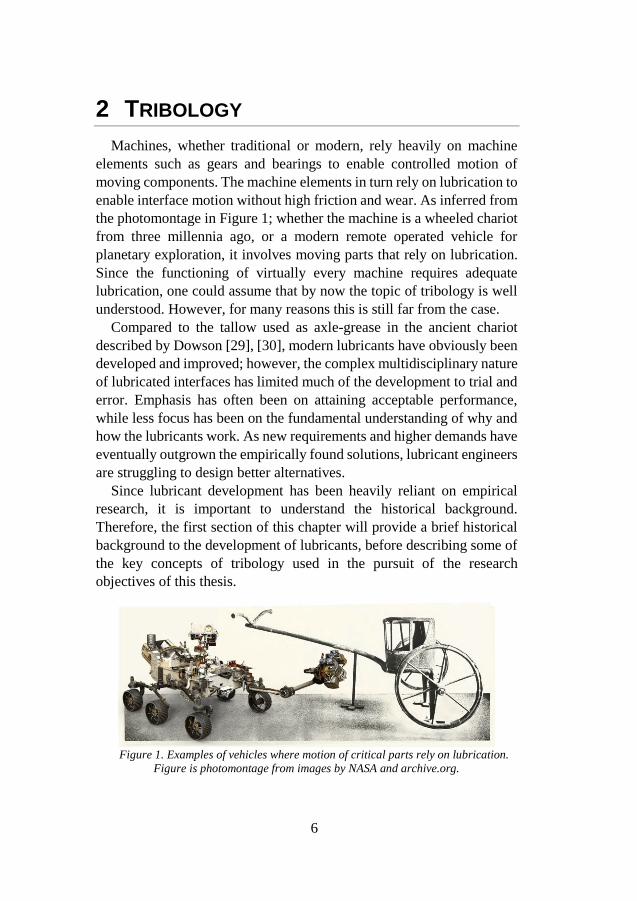
enable interface motion without high friction and wear. As inferred from
the photomontage in Figure 1; whether the machine is a wheeled chariot
from three millennia ago, or a modern remote operated vehicle for
planetary exploration, it involves moving parts that rely on lubrication.
Since the functioning of virtually every machine requires adequate
lubrication, one could assume that by now the topic of tribology is well
understood. However, for many reasons this is still far from the case.
Compared to the tallow used as axle-grease in the ancient chariot
described by Dowson [29], [30], modern lubricants have obviously been
developed and improved; however, the complex multidisciplinary nature
of lubricated interfaces has limited much of the development to trial and
error. Emphasis has often been on attaining acceptable performance,
while less focus has been on the fundamental understanding of why and
how the lubricants work. As new requirements and higher demands have
eventually outgrown the empirically found solutions, lubricant engineers
are struggling to design better alternatives.
Since lubricant development has been heavily reliant on empirical
research, it is important to understand the historical background.
Therefore, the first section of this chapter will provide a brief historical
background to the development of lubricants, before describing some of
the key concepts of tribology used in the pursuit of the research
objectives of this thesis.
Figure 1. Examples of vehicles where motion of critical parts rely on lubrication.
Figure is photomontage from images by NASA and archive.org.
7
2.1 HISTORICAL EVENTS TOWARDS TRIBOLOGY As previously mentioned, machinery lubricants have been employed
for at least thousands of years. However, the first recorded experiments
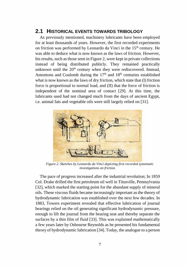
on friction was performed by Leonardo da Vinci in the 15th century. He
was able to deduce what is now known as the laws of friction. However,
his results, such as those seen in Figure 2, were kept in private collections
instead of being distributed publicly. They remained practically
unknown until the 20th century when they were rediscovered. Instead,
Amontons and Coulomb during the 17th and 18th centuries established
what is now known as the laws of dry friction, which state that (I) friction
force is proportional to normal load, and (II) that the force of friction is
independent of the nominal area of contact [29]. At this time, the
lubricants used had not changed much from the days of ancient Egypt,
i.e. animal fats and vegetable oils were still largely relied on [31].
Figure 2. Sketches by Leonardo da Vinci depicting first recorded systematic
investigations on friction.
The pace of progress increased after the industrial revolution; In 1859
Col. Drake drilled the first petroleum oil well in Titusville, Pennsylvania
[32], which marked the starting point for the abundant supply of mineral
oils. These viscous fluids became increasingly important as the theory of
hydrodynamic lubrication was established over the next few decades. In
1883, Towers experiment revealed that effective lubrication of journal
bearings relied on the oil generating significant hydrodynamic pressure,
enough to lift the journal from the bearing seat and thereby separate the
surfaces by a thin film of fluid [33]. This was explained mathematically
a few years later by Osbourne Reynolds as he presented his fundamental
theory of hydrodynamic lubrication [34]. Today, the analogue to a person
8
water-skiing can be made to visualize the principle of hydrodynamic
lubrication. In the following decades, Stribeck and Hersey continued the
work on hydrodynamic lubrication which led to what is now the classic
‘Stribeck curve’ [35]. This curve forms the basis of the concept of
lubrication regimes, and identifies the importance of adequate lubricant
viscosity.
In 1922 Hardy and Doubleday [36], [37] investigated the other major
lubrication regime – boundary lubrication – where hydrodynamic effects
are negligible and solid asperities instead carry the load. They found that
extremely thin films adsorbed on the surfaces had a significant effect on
sliding friction. They concluded that chemical composition of the
lubricant is important in this regime. In the next decades, lubricant
manufacturers began experimenting with dissolving chemicals in oils to
reduce friction and wear. Some very effective lubricant additives where
found by the 1940’s [38]. Bowden and Tabor continued the scientific
study of boundary lubrication in the 1950’s and developed the theory of
adhesive friction [39], [40].
During the 1960’s, the British government requested an oversight of
how industry efficiency could be improved by research related to
friction, wear, and lubrication. This finally led to the coining of the word
‘tribology’ by H Peter Jost in his now famous report [41]. The report
defined the topic of tribology as the science and technology of interacting
surfaces in relative motion. It emphasized the point that scientific studies
of lubrication are highly multidisciplinary, requiring collaborations of
experts in fields of mechanical engineering, chemistry, physics, and
metallurgy – a point that is still very much valid today.
2.2 DEFINITIONS
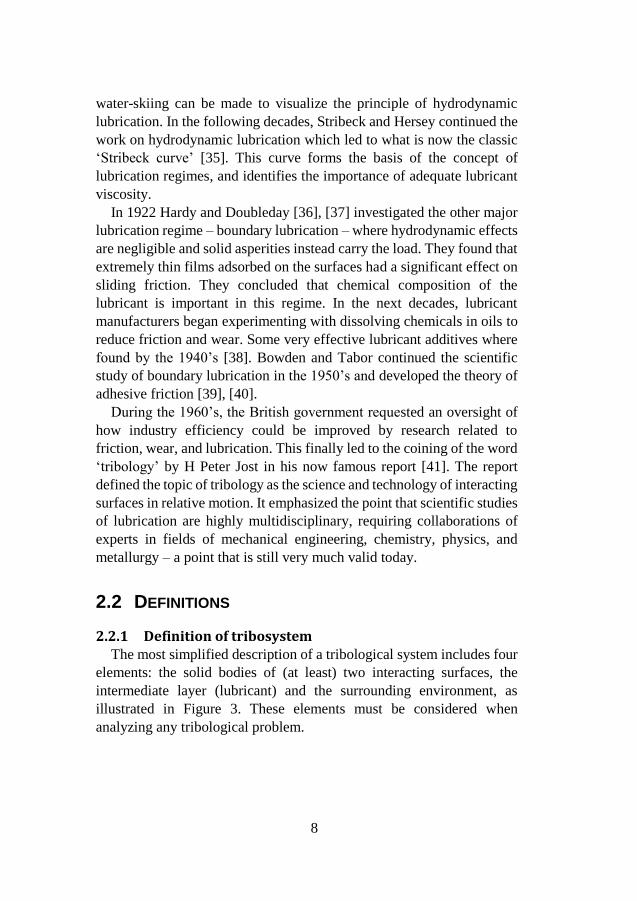
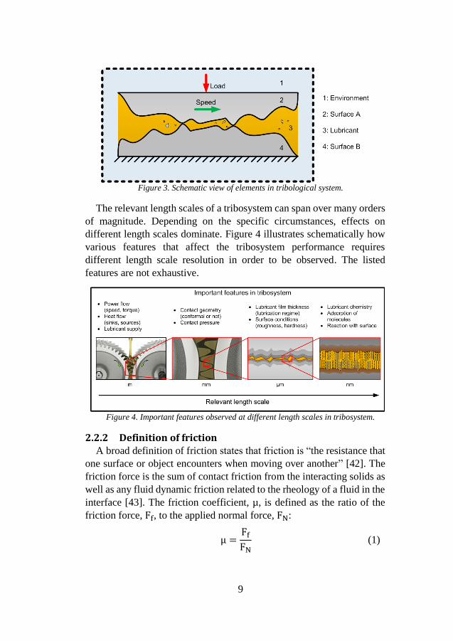
2.2.1 Definition of tribosystem The most simplified description of a tribological system includes four
elements: the solid bodies of (at least) two interacting surfaces, the
intermediate layer (lubricant) and the surrounding environment, as
illustrated in Figure 3. These elements must be considered when
analyzing any tribological problem.
9
Figure 3. Schematic view of elements in tribological system.
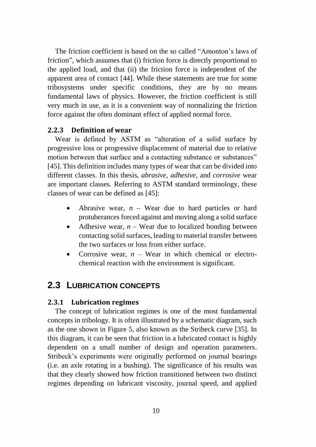
The relevant length scales of a tribosystem can span over many orders
of magnitude. Depending on the specific circumstances, effects on
different length scales dominate. Figure 4 illustrates schematically how
various features that affect the tribosystem performance requires
different length scale resolution in order to be observed. The listed
features are not exhaustive.
Figure 4. Important features observed at different length scales in tribosystem.
2.2.2 Definition of friction A broad definition of friction states that friction is “the resistance that
one surface or object encounters when moving over another” [42]. The
friction force is the sum of contact friction from the interacting solids as
well as any fluid dynamic friction related to the rheology of a fluid in the
interface [43]. The friction coefficient, µ, is defined as the ratio of the
friction force, Ff, to the applied normal force, FN:
µ =
Ff
FN (1)
10
The friction coefficient is based on the so called “Amonton’s laws of
friction”, which assumes that (i) friction force is directly proportional to
the applied load, and that (ii) the friction force is independent of the
apparent area of contact [44]. While these statements are true for some
tribosystems under specific conditions, they are by no means
fundamental laws of physics. However, the friction coefficient is still
very much in use, as it is a convenient way of normalizing the friction
force against the often dominant effect of applied normal force.
2.2.3 Definition of wear Wear is defined by ASTM as “alteration of a solid surface by
progressive loss or progressive displacement of material due to relative
motion between that surface and a contacting substance or substances”
[45]. This definition includes many types of wear that can be divided into
different classes. In this thesis, abrasive, adhesive, and corrosive wear
are important classes. Referring to ASTM standard terminology, these
classes of wear can be defined as [45]:
Abrasive wear, n – Wear due to hard particles or hard
protuberances forced against and moving along a solid surface
Adhesive wear, n – Wear due to localized bonding between
contacting solid surfaces, leading to material transfer between
the two surfaces or loss from either surface.
Corrosive wear, n – Wear in which chemical or electro-
chemical reaction with the environment is significant.
2.3 LUBRICATION CONCEPTS
2.3.1 Lubrication regimes The concept of lubrication regimes is one of the most fundamental
concepts in tribology. It is often illustrated by a schematic diagram, such
as the one shown in Figure 5, also known as the Stribeck curve [35]. In
this diagram, it can be seen that friction in a lubricated contact is highly
dependent on a small number of design and operation parameters.
Stribeck’s experiments were originally performed on journal bearings
(i.e. an axle rotating in a bushing). The significance of his results was
that they clearly showed how friction transitioned between two distinct
regimes depending on lubricant viscosity, journal speed, and applied
11
load. Hersey plotted the data as a function of a non-dimensional
parameter, H, defined in equation 2:
H =
ηn
p , (2)
where η is the fluid dynamic viscosity [Pa ∙ s], n is the journal rotational
speed [s−1] , and p is the average pressure [Pa] . Although initially
intended for journal bearings, the principle can be more broadly applied
to any contact having a converging gap. It illustrates the important effects
of viscosity, sliding speed, and load to the regime of lubrication, and also
the non-linear response of friction and wear to a shift in lubrication
regime.
The reason why friction decreases with increasing H is that under
favorable conditions, the hydrodynamic pressure in the fluid builds up to
eventually relieve the surfaces of solid-solid contact. In the design of
bearings and gears, it is very useful to predict when the transition
happens. The height of the generated lubricant film can be calculated
numerically [18], and this can be compared to the average roughness of
the surfaces to estimate the amount of surface separation. The non-
dimensional film thickness ratio, λ, is thus defined as:
λ =hmin
√(Rq,A)2
+(Rq,B)2 ,
(3)
where hmin is the minimum lubricant film thickness [18], and Rq,i is the
RMS roughness of surfaces A and B. The ratio λ > 3 is normally
sufficient to ensure full film lubrication, while λ < 1 indicates
significant solid-solid interaction.
12
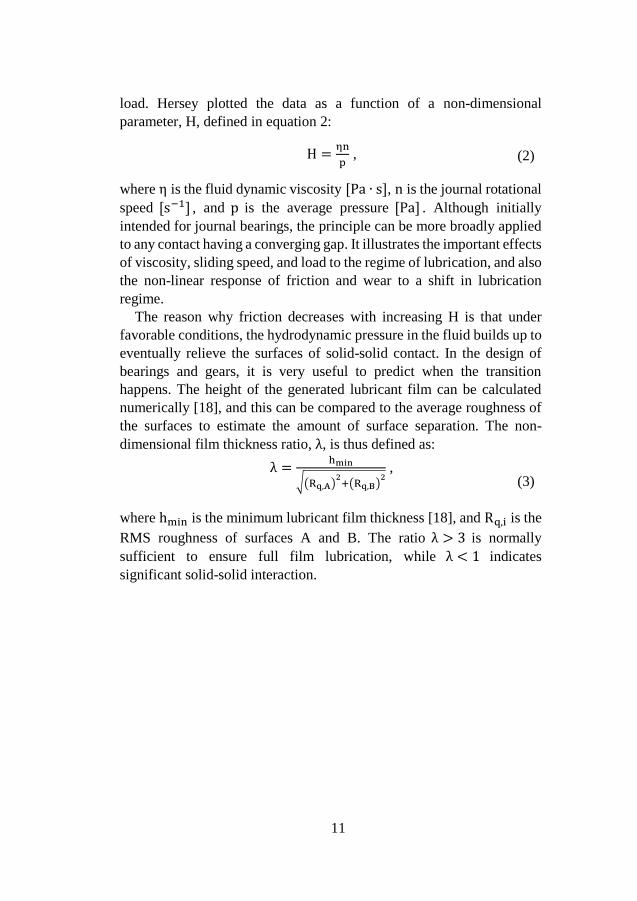
Figure 5. Schematic diagram describing concept of lubrication regimes, known as
Stribeck-curve.
The regimes in the Stribeck curve can be divided into Boundary
Lubrication (BL), Mixed Lubrication (ML), and Hydrodynamic
Lubrication (HL) regimes. In BL where λ < 1, the majority of the load
is carried by solid-solid contact, with consequent risk of high friction and
wear. As the ratio of lubricant film thickness to roughness increase, the
system transitions into ML, where the solid asperities of the surfaces are
still in contact but fluid pressure also becomes significant. In the HL
regime, λ > 3, the fluid pressure is high enough to fully separate the
surfaces from contact by a continuous fluid film. If the geometry of the
contact is non-conformal, the pressure can rise to a sufficiently high
magnitude so that the surfaces deform elastically. In the latter case, the
regime is referred to as elasto-hydrodynamic lubrication (EHL). The
term Full Film Lubrication (FFL) is also sometimes used to indicate the
HL or EHL regimes.
It should be noted that the distinction between ML and BL is
somewhat arbitrary, and it is often impossible to establish in practice. In
ML or BL, the roughness of the surfaces continuously change by the
wear process and by surface boundary films being generated via
chemical reactions. Therefore, in the remainder of this text, the reference
to boundary lubrication will indicate that boundary effects dominate, but
effects of fluid rheology are not automatically disregarded.
13
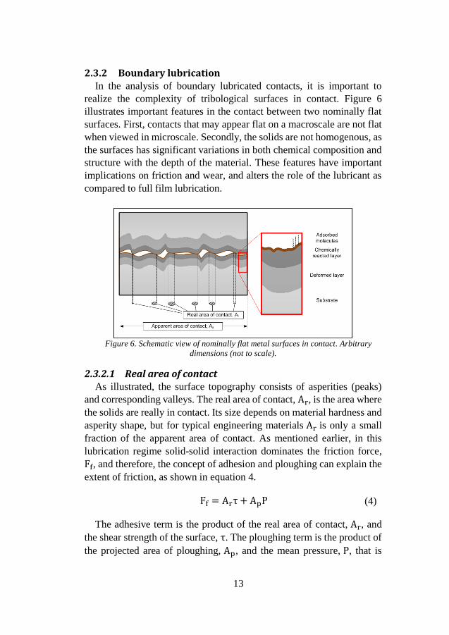
2.3.2 Boundary lubrication In the analysis of boundary lubricated contacts, it is important to
realize the complexity of tribological surfaces in contact. Figure 6
illustrates important features in the contact between two nominally flat
surfaces. First, contacts that may appear flat on a macroscale are not flat
when viewed in microscale. Secondly, the solids are not homogenous, as
the surfaces has significant variations in both chemical composition and
structure with the depth of the material. These features have important
implications on friction and wear, and alters the role of the lubricant as
compared to full film lubrication.
Figure 6. Schematic view of nominally flat metal surfaces in contact. Arbitrary
dimensions (not to scale).
2.3.2.1 Real area of contact As illustrated, the surface topography consists of asperities (peaks)
and corresponding valleys. The real area of contact, Ar, is the area where
the solids are really in contact. Its size depends on material hardness and
asperity shape, but for typical engineering materials Ar is only a small
fraction of the apparent area of contact. As mentioned earlier, in this
lubrication regime solid-solid interaction dominates the friction force,
Ff, and therefore, the concept of adhesion and ploughing can explain the
extent of friction, as shown in equation 4.
Ff = Arτ + ApP (4)
The adhesive term is the product of the real area of contact, Ar, and
the shear strength of the surface, τ. The ploughing term is the product of
the projected area of ploughing, Ap, and the mean pressure, P, that is
14
required to plastically displace material. The details can be found in [39].
However, the key points are the following: (i) both adhesion and
ploughing terms are inversely related to the hardness of the solids, as the
hardness dominates the size of both areas. (ii), for hard and smooth
materials where the ploughing term is minimal, the shear stress is directly
proportional to the force of adhesion. These two points imply that a hard,
smooth surface covered by an easily sheared layer is the optimum for
friction reduction.
2.3.2.2 Surface inhomogeneity Regarding the inhomogeneity; the uppermost layer of the surface
(thickness <1 nm) consists of adsorbed molecules from the surrounding
environment. Beneath the adsorbed layer is a chemically reacted layer
(thickness 10–100 nm), initially consisting of oxides formed by reaction
with oxygen in air. Continuing further into the material, layers have
likely been affected by the manufacturing process; for example, they can
be strain hardened, or annealed. The affected depth depends on the
specific manufacturing process but is likely to be in the micrometer range
[31]. These layers have significant effects on friction and wear, and vice
versa. Oxides are especially critical as they can be considered an inherent
boundary film that prevent material adhesion and the consequent risk of
seizure.
2.3.2.3 Role of lubricant In BL, fluid rheology is important to friction and wear mainly by
indirect factors. The viscosity is only of minor influence, as
hydrodynamic pressure is insignificant. On the other hand, effective
rheology is important in key lubricant tasks such as heat transfer,
transport of additives, and flushing out wear particles. The most
important role of conventional lubricant fluids in BL however, is the
ability to transport chemically active additives to the surface so that they
can form boundary films.
Lubricants are commonly formulated by adding chemically active
species to the base fluid. These triboimproving additives are usually
classified as friction modifiers (FM), anti-wear (AW), or extreme
pressure (EP), depending on their intended role [46]. Typical FMs reduce
friction by forming closely packed layers of adsorbed molecules. The
molecules consist of polar head groups and lipophilic hydrocarbon tails,
with carbon numbers typically ranging from 12–20. AW additives reacts
15
with surfaces, typically forming robust films that reduce wear. AWs
generally do not reduce friction, in fact they are likely to increase
friction. Finally, EP additives are used to minimize the risk of seizure at
extreme pressure conditions. EP additives react aggressively to surfaces
in a manner that reduces the cohesive strength of the surface. Therefore,
contrary to AWs, EPs actually increase wear when added to base fluids,
but they can be considered as an insurance against the risk of seizure.
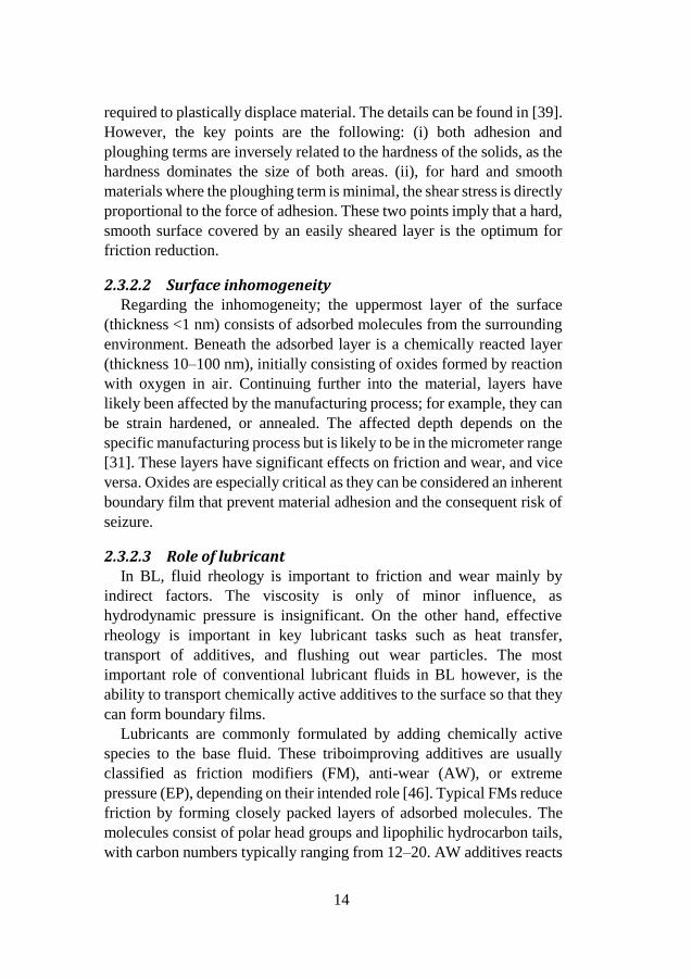
Figure 7 explains how additive-surface reactions must be balanced
depending on the operating conditions. Ideally, the boundary film should
be generated at a rate that is in balance with the rate of wear, so that the
boundary film is being continuously replenished [47].
Figure 7. The reactivity of lubricant towards surface should be balanced to achieve
optimum rate of boundary film formation depending on operating conditions.
16
3 LUBRICATION IN SPACE ENVIRONMENT
Mechanisms operating in space environment are notoriously
troublesome to lubricate for a number of reasons. The lack of an air
atmosphere has two major implications from a tribological point of view;
first, vacuum causes conventional liquid lubricants to boil already at
ambient temperatures. Secondly, the lack of an oxygen environment
precludes the generation of the important oxide boundary layers
previously discussed. The combination of these factors is problematic,
since the first factor makes the use of fluid film lubrication more difficult,
while the second factor has a very antagonistic effect on boundary
lubrication. Other factors to consider include effects of radiation and
gravity, as well as transient accelerations during launch, landing, or
atmospheric entry. Ionized gases and atomic oxygen can be highly
reactive and are frequently encountered in low earth orbit (LEO).
Furthermore, the poor heat transfer caused by the absence of an
atmosphere can lead to severe thermal conditions. All these mentioned
problems were realized already at the beginning of the space age, and
many of them have by now been studied for more than 50 years [15],
[48], [49].
Still, troubles caused by tribology are frequently encountered. Some
recent examples of this ‘troubology’ include the international space
station (ISS), which has been the subject of a number of spectacular
maintenance efforts. Control moment gyroscopes have been replaced
after suffering unexpected bearing seizures [50], [51], and the failure of
a massive 3.2 m diameter solar array rotary joint bearing required
astronauts to perform mechanical maintenance using spare parts and
lubricant delivered by space shuttle [52]–[54]. However, other than the
ISS, there are few examples of spacecraft where maintenance is possible.
Therefore, tribological issues are recognized as one of the large risk
factors to premature failures in satellites [55], and a number of major
space missions have encountered troubles or close encounters that can
be attributed to “troubology” [56]–[59]. Lubricants and tribology is
therefore a critical topic to reliable space missions.
17
3.1 LUBRICANTS USED IN SPACE APPLICATIONS
3.1.1 Note on solid lubricants Lubrication approaches to counter the adverse effects of space
environment include both solid and fluid lubricants, however, in this
thesis the focus is on liquid lubricants as they are deemed most feasible
for the sliding contacts subjected to high contact pressures identified as
a research gap. Significant efforts have been made to develop solid
lubricants for operations in Mars environment [60], [61]. However, it
seems difficult to overcome the fundamental limitations inherent to this
approach [19], [62], [63]. Sliding contacts at high pressures will
inevitably generate heat at the asperities in contact, and the heat must be
efficiently dissipated in order to avoid overheating and seizure. The low
pressure atmospheres (or vacuum) in space almost eliminates heat
transfer by gas convection. The thermal situation is made worse by the
fact that commonly used metals like titanium-alloys or stainless steels
generally have poor thermal conductivity. In the absence of a liquid
lubricant to cool the contact, the local asperity contact temperature is
therefore likely to rise uncontrolled during continuous operation. Solid
lubricants will therefore have major difficulties in maintaining stable
contact temperatures in sliding contacts subjected to continuous high
pressure, which is in line with recent observations [62].
3.1.2 liquid lubricants As mentioned previously, conventional liquid lubricants boil and
vaporize in vacuum. For this reason, the liquid lubricants commonly
employed in space applications are almost exclusively limited to the low
vapor pressure fluids perfluoropolyethers (PFPEs) and multiply
alkylated cyclopentanes (MACs) [64]–[67]. These compounds have high
molecular weights for fluids, which is critical to the mechanism of low
vapor pressure.
For a liquid to evaporate or boil, it must undergo a phase change from
liquid to gas. The ability to do so depends on the enthalpy of vaporization
of the substance that in turn depends on the sum of intermolecular forces.
Strong intermolecular forces are thus essential for fluids in vacuum.
The respective strength of intermolecular forces is arranged as
following: Ionic bonds > hydrogen bonds > dipole-dipole interaction>
van der Waals forces. This would indicate that non-polar fluids such as
MACs or PFPEs would have weak intermolecular forces since they rely
18
on van der Waals forces. However, van der Waals forces are proportional
to surface area of the molecule, and therefore high molecular weight
(HMW) fluids can generate significant intermolecular force. This is the
principle of how PFPEs and MACs are resistant to vaporization in
vacuum environments.
PFPE was developed more than 50 years ago [68], and has significant
heritage in space [69], [70]. PFPE has outstanding thermal stability, and
extremely low vapor pressure. Despite the heritage, PFPE has some well-
known issues. It is regarded as a very inert fluid, however, in BL
conditions it is known to degrade and release fluorine. The fluorine can
initially be of benefit as it reacts with metal surfaces to provide a
boundary film of iron fluoride, however, the mechanism becomes
autocatalytic and degrades the fluid [71], [72]. It is likely that the large
HMW molecules are subjective to mechanical shearing in BL. As the
molecule is degraded, fluorine is released and reacts with metal to form
the autocatalytic iron fluoride [73]. Additives for PFPE to improve BL
properties have been researched for some time [74], [75], and are still
ongoing [76]. However, if the core issue is mechanical scission of the
HMW molecule it seems difficult to prevent by additives.
MACs on the other hand are synthetic hydrocarbons [77]. As they are
fluorine free, they do not suffer the autocatalytic degradation.
Unfortunately, they do have other issues. As the MACs are pure
hydrocarbons, they are poor boundary lubricants and require additives to
avoid seizure in BL. Additive technology is being researched [78]–[80]
to improve performance in BL. However, MACs also have the inherent
problem of de-wetting caused by high surface tension [81].
3.2 CONSIDERATIONS OF MARS APPLICATION There are a number of key differences when comparing tribology for
Mars missions to satellites or deep space missions. From a tribological
point of view, the environment of Mars is well known [82]. The
atmospheric pressure on Mars is in the range of approximately 10+3 Pa,
which is less than 1% of the atmospheric pressure on Earth. However, it
is considerably higher than the vacuum encountered by satellites, which
is generally below 10-5 Pa [16]. The atmosphere on Mars consists of 95
% CO2, with Argon and Nitrogen as the other significant gases. As on
Earth, temperature varies with latitude, elevation, and time of year, and
time of day. Ground temperatures frequently measured in exploration
19
missions range between approximately -100 and +30 °C [83], and for
that reason electrical heaters are required when using liquid lubricants
[84]. PFPE lubricants are easily able to meet the requirements on
pressure, and have fair low temperature fluidity. For these reasons, PFPE
has been heavily relied on for Mars missions [19], [85]–[87].
As can be seen, there are liquid lubricants that can withstand the
ambient conditions. The major problem however, is the combination of
ambient conditions with the conditions faced in the tribological contact.
Typical MMAs include gears and bearings in electromechanical
actuators. These systems are essential to current and future in-situ
exploration missions that require operations such as drilling into rocks to
retrieve samples, or driving over rough terrain for example. As these
MMAs operate in the Martian gravity of roughly 3.7 m/s2, these
operations have more similarities to MMAs on Earth than MMAs on
satellites. Due to the size and weight constraints inherent to transporting
equipment to Mars, the MMAs are heavily loaded, and operate with
minimal amounts of lubricant. They are therefore more likely to operate
in BL conditions [88].
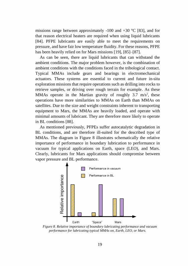
As mentioned previously, PFPEs suffer autocatalytic degradation in
BL conditions, and are therefore ill-suited for the described type of
MMAs. The diagram in Figure 8 illustrates schematically the relative
importance of performance in boundary lubrication to performance in
vacuum for typical applications on Earth, space (LEO), and Mars.
Clearly, lubricants for Mars applications should compromise between
vapor pressure and BL performance.
Figure 8. Relative importance of boundary lubricating performance and vacuum
performance for lubricating typical MMAs on, Earth, LEO, or Mars.
20
4 IONIC LIQUID LUBRICANTS
4.1 BACKGROUND OF IONIC LIQUIDS Ionic liquids (ILs) are fluids composed entirely of ions; positive
charged cations and negative charged anions are combined in a ratio that
balances the net charge. ILs can therefore be described as salts in the
molten state. There is no formally agreed definition of the term ionic
liquid, and the terms molten salt, fused salt, and room temperature ionic
liquid (RTIL) is sometimes used interchangeably. The distinction
between molten salt and ionic liquid is made at a melting point of 100
°C, so that an ionic liquid is defined to have a melting point below 100
°C while a molten salt has a higher melting point. The term room
temperature ionic liquid is used to emphasize that the melting point is
well below 100 °C, however, as this type of IL has become increasingly
common, the prefix ‘room temperature’ is becoming less widely used.
Regardless of the term, salts in the liquid state have a number of
interesting, unusual, and useful properties compared to common fluids.
The strong ionic bonds reduce the tendency for the fluids to vaporize,
giving the fluid a wide liquid range. This implies that molten salts can
absorb significant heat without increased pressure, and therefore they
were researched as heat transfer media in the early days of nuclear power
[89], [90]. The first example of a molten salt lubricant can be found from
this era, as molten salt mixture was used experimentally in
hydrodynamic bearings [91]. However, as the melting point of this mixed
salt was above 500 °C, the practical applications were few.
In the molten state, the mobility of the ions gives rise to electric
conductivity of the fluid. This led to the development of batteries that
could be thermally activated by pyrotechnics. Wilkes describes how
research was conducted to design salts with lower melting points, which
are precursors to what is today called ionic liquids [92]. The original
molten salts had relatively simple chemical structures; however, the
melting point could be reduced by introducing bulkier ions of
asymmetric structure, as they reduce the Coulombic interactions between
ions and prevent crystallization. On the other hand, the other
intermolecular forces, such as van der Waals, hydrogen bonding, can
become influential [93]. The broad range of intermolecular forces gives
ILs very useful properties as solvents. This implies the possibility of
21
tuning the IL towards solubility of selected compounds, and the ability
to catalyze certain reactions. These properties of non-volatility, solubility
and tunability is what led to the real breakthrough in ionic liquids in the
late 1990’s [94]–[97].
Although the synthesis of ionic liquids is outside the scope of this
work, it is appropriate to make a note on how ILs can be synthesized. An
ionic liquid with target cation, C, and target anion, A, can be prepared by
the combination of two different salts by a metathesis reaction. Consider
a halide salt, C–X, and an alkali salt, A–M. These can each be prepared
individually to design C and A. The IL is formed when the salts are
combined. The alkali metal, M, preferentially bonds to the halogen, X,
forming an inorganic salt M–X. The target anion (A) that was originally
bonded to the alkali metal (M) will instead bond to the target cation (C),
resulting in the ionic liquid C–A. The process is described in equation 5.
[C–X] + [M–A] → [C–A] + [M–X] (5)
Many of the commonly used cations are commercially available as
halide salts, and thus only require the anion exchange and purification
process. In other cases, cations can be formed by quaternization of
amines, phosphines, or sulfides by a well-known route using haloalkanes
[98]. Imidazolium, tetraalkylammonium, and tetraalkylphosphonium are
examples of cations that can be found as commercially available halide
salts at reasonable cost, where only anion exchange reaction is required
to form an ionic liquid [98]. These cations have are thus frequently
reported.
4.2 IONIC LIQUIDS IN TRIBOLOGY In 2001, Ye et al evaluated non-volatile imidazolium tetrafluoroborate
ILs based on properties such as suitable melting point and viscosity, high
thermal stability, and hygroscopicity for evaluation as lubricant [25]. The
result showed that the IL reduced friction and wear compared to the
reference lubricants. Although the test was performed in air atmosphere,
the choice of PFPE as reference lubricant implied the possibility that ILs
could provide an alternative to the established vacuum lubricants.
The properties inherent to ionic liquids, such as low vapor pressure,
high thermal and chemical stability, and high heat transfer capacity are
very appealing in tribology. Therefore, ILs have garnered significant
22
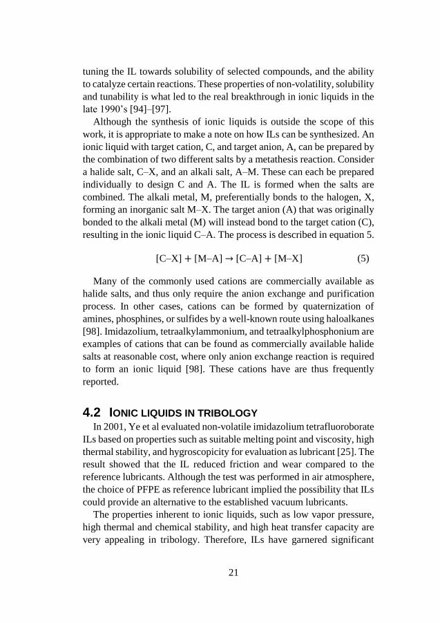
interest for use as advanced lubricants. However, as seen in Figure 9
ionic liquid lubricants is only a small subset of the ionic liquid research
field, and consequently most ILs evaluated were designed for other
purposes than lubrication.
Figure 9. Results of searching the Scopus database with the search term "ionic
liquid(s)", and filtering the results for “tribolog(...) or lubric(...)”.
As explained previously, the IL properties depend on the anion-cation
combination used, and with countless possible combinations it is
possible to design task specific lubricants [99]–[101]. Despite this
immense number of possible ILs, most tribological evaluations have
focused on the relatively small number of anions which are readily
available, such as BF4, PF6, and TFSA [26], [28]. While these fluorine-
containing anions can reduce friction and wear by forming boundary
films composed of metal fluorides, the reactivity is not well balanced;
they have been frequently reported to cause corrosive wear [102]–[104].
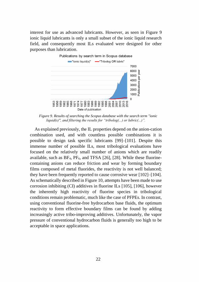
As schematically described in Figure 10, attempts have been made to use
corrosion inhibiting (CI) additives in fluorine ILs [105], [106], however
the inherently high reactivity of fluorine species in tribological
conditions remain problematic, much like the case of PFPEs. In contrast,
using conventional fluorine-free hydrocarbon base fluids, the optimum
reactivity to form effective boundary films can be found by adding
increasingly active tribo-improving additives. Unfortunately, the vapor
pressure of conventional hydrocarbon fluids is generally too high to be
acceptable in space applications.
23
Figure 10. High reactivity of common ILs compared to hydrocarbons.
In order to reduce the corrosiveness of ILs, the fluorine atom(s) can
be removed; however, further improvements in tribological properties
are required [107], [108].
4.3 POTENTIAL OF DESIGNING IL AS LUBRICANT In molecular design of any substance, the ultimate goal is to be able
to predict a chemical structure that provides a desired set of material
properties. The design does not necessarily include the route of how the
chemical structure is attained, however, it is useful to limit the number
of possible designs to those that are most practical. This analysis
however, is not included in the scope of this thesis.
Regarding molecular design of lubricants, the effect of chemical
structures on bulk properties such as viscosity, thermal stability and
vapor pressure are well known, especially at ambient conditions [109],
[110]. Regarding boundary lubricants, the situation becomes more
complicated due to the dynamic temperatures, pressures, and mechanical
shearing of molecules. Also, practical lubricants are mixtures of many
active compounds, both intended (different additives) and unintended
(wear particles, contaminants). Even though this is far from ideal
laboratory conditions, empirical research over many decades have
provided some insight into the mechanism of triboimproving additives
[111]–[114]. The correlation between chemical structures and lubricant
performance is still far from complete and is still evolving [115]–[117].
However, the topic of tribochemistry has advanced lubricant
24
formulations from trial and error towards a scientific method of testing
hypothesis in a controlled stepwise manner.
For ionic liquids in boundary conditions, the situation is even more
complex. As mentioned earlier, ILs have many types of intermolecular
forces and a slight change in the chemical structure can tip the balance
between these forces. As an example, unexpected crystallization from
some structures have been reported [98]. Still, by employing a stepwise
approach of molecular design, it has been possible to improve the design
of lubricant additives [118]–[120] and potentially also of ionic liquids.
Targeting a low pressure atmosphere in the range of ~1 kPa instead of
the common ultra-high vacuum applications relaxes the demands on
volatility somewhat, and leads to the possibility to focus more on
improving tribological properties.
25
5 MATERIALS AND METHODS
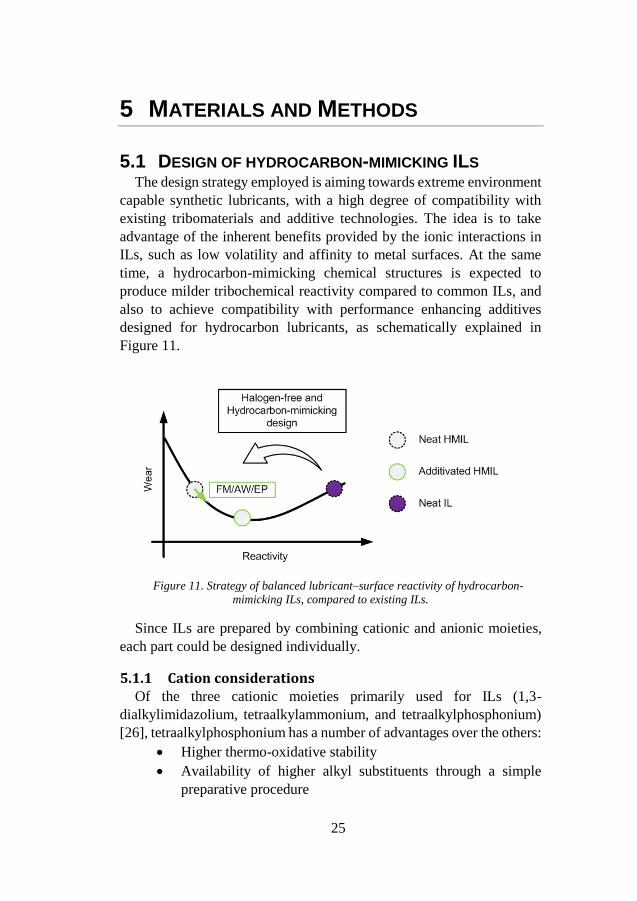
5.1 DESIGN OF HYDROCARBON-MIMICKING ILS The design strategy employed is aiming towards extreme environment
capable synthetic lubricants, with a high degree of compatibility with
existing tribomaterials and additive technologies. The idea is to take
advantage of the inherent benefits provided by the ionic interactions in
ILs, such as low volatility and affinity to metal surfaces. At the same
time, a hydrocarbon-mimicking chemical structures is expected to
produce milder tribochemical reactivity compared to common ILs, and
also to achieve compatibility with performance enhancing additives
designed for hydrocarbon lubricants, as schematically explained in
Figure 11.
Figure 11. Strategy of balanced lubricant–surface reactivity of hydrocarbon-
mimicking ILs, compared to existing ILs.
Since ILs are prepared by combining cationic and anionic moieties,
each part could be designed individually.
5.1.1 Cation considerations Of the three cationic moieties primarily used for ILs (1,3-
dialkylimidazolium, tetraalkylammonium, and tetraalkylphosphonium)
[26], tetraalkylphosphonium has a number of advantages over the others:
Higher thermo-oxidative stability
Availability of higher alkyl substituents through a simple
preparative procedure
26
The n-alkyl group has a structure analogous to that of friction
modifiers
Metal phosphate boundary film precursor [121]
The presence of higher alkyl groups make the molecules
hydrophobic and increase the hydrocarbon content, in line
with the hydrocarbon-mimicking strategy.
5.1.2 Anion considerations As for the anionic moiety, fluorine-containing ones are commonly
used. Fluorine is highly electronegative and if incorporated in a molecule,
it stabilizes the negative charge on the molecule and makes the molecule
hydrophobic. Further, it forms strong covalent bonds with other atoms
such as those of carbon, thereby improving the thermo-oxidative stability
of the molecule. It also makes the molecule bulky, as its atomic radius is
higher than that of hydrogen. Owing to these outstanding properties,
fluorine-based anionic moieties are highly suited for use in ILs.
However, as mentioned previously, fluorine also exhibits a significant
disadvantage with respect to tribological applications, in that it can cause
tribo-induced corrosion. One option for replacing halogens is by use of
pseudo-halogen functional groups. This was investigated in 2012 by
Minami et al [107]. The continuation of this work focused on alkyl
oxoacids such as phosphates [122], sulfonates [123], and carboxylates.
The alkyl group in these acids enables the possibility to modify fluid
properites by changing the functional group(s). Trimethylsilyl-
substituted alkyl sulfonates are one recent example [124], [125]. Based
on the results of the previous research, trimethylsilylalkylsulfonate was
considered as anion. The structural features of the anion as lubricant are
the following:
The sulfonate can act as an anchor, allowing the molecule
to be adsorbed on metal surfaces by forming a boundary
film
The trialkylsilyl group has a structure corresponding to one
with quaternary carbons and can be expected to result in
better rheological properties [126]
The additional hydrocarbon units present on the silicon
atom induce oleophilic and hydrophobic properties
In addition, the phosphonium cation and trialkylsilyl unit in the anion
makes the molecules bulky; this lowers the glass transition temperature
27
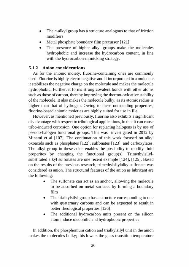
of the resultant ILs. Based on this strategy, several ILs were prepared
from tetraalkylphosphonium chloride and sodium
trimethylsilylalkylsulfonate, which are commercially available reagents,
by a one-step metathesis process. The intended function of each moiety
is shown in Figure 12.
Figure 12. Expected function of each moiety.
5.2 EXPERIMENTAL PROCEDURE
5.2.1 Lubricant data The hydrocarbon-mimicking ILs have the chemical formula [(n-
CαH2α+1)3(n-CβH2β+1)P]·[(CχH2χ+1)3Si(CH2)δSO3] and are designated as P-
SiSO[α-β][χ-δ]. P-SiSO has been used as base fluid in all experiments.
P-SiSO was synthesized by Nisshinbo Holdings Inc. (Tokyo, Japan).
Low vapor pressure fluids (Fomblin Y) –– designated as PFPEs — were
supplied by Sigma-Aldrich (Stockholm, Sweden) and have been used as
reference lubricant. The linear formula of PFPE is CF3O[–
CF(CF3)CF2O–]x(–CF2O–)yCF3, and it is used in two different viscosity
grades, designated as PFPE-L and PFPE-H. A conventional RTIL, 1-
butyl-3-methylimidazolium bis(trifluoromethane-sulfonyl)amide
([BMIM][TFSA]) was used as reference in Paper I. Several additives
have been evaluated in Paper I and Paper II. Two of them are reported in
this summary, and are referred to as PNA (N-Phenyl-1-naphthylamine,

28
reagent grade, 98%) and OPP (Ortho-phenylene phosphate, prepared as
described in Reference [127]). The additives were added at a
concentration of 10 mmol/kg. See Figure 13 for chemical structures.
Figure 13. P-SiSO base fluid and selected additives from Paper II.
5.2.2 Tribotesting An Optimol SRV tribotester in the ball-on-flat configuration was used
to evaluate the lubrication performance. In accordance with test standard
ASTM D6425-11, a 10 mm ball was pressed against the top of a flat
stationary disc while being subjected to a linearly reciprocating motion
with an amplitude of 1.0 mm and frequency of 50 Hz. The ball and disc
were made of AISI 52100 bearing steel as specified in the test standard.
All the tests were conducted in air, with the relative humidity being ~25–
50%. The test temperature was controlled by heating the disc support.
Three parameters were varied during the tests in this study: normal load,
test temperature, and test duration. These were either held constant
(denoted C) or were varied (denoted V) during the test. The following
code was used to identify the conditions in the various cases: C{P/T/D}
or V{P1–P2/T1–T2/D}, where P, T, and D represent maximum Hertzian
pressure [128], test temperature, and test duration respectively. The
subscript 1 indicates the nominal minimum value, while subscript 2
indicates the nominal maximum value of a parameter being varied during
the test.
5.2.3 Surface analysis
5.2.3.1 Quantification of wear The degree of wear was quantified by means of wear scar analyses
performed using 3D optical surface profiling by white light
interferometry using a Zygo NewView 7300 instrument (Zygo
29
Corporation, Middlefield, CT, USA). In this work, the measured wear
scar diameter (WSD) is reported in relation to the Hertzian contact
diameter (HzD) [128], by a parameter designated as WHz [129], [130].
Furthermore, it was assumed that the wear scar diameter would never be
less than the Hertz contact diameter, since the tests were started from
standstill with a full load applied and therefore the initial contact patch
would inevitably be scratched. Thus, the following condition holds, and
WHz was used to quantify wear:
WHz = WSD/HzD ≥ 1 (6)
5.2.3.2 SEM-EDS analysis SEM and EDS were used for recording high magnification images and
analyzing the chemical composition of tribofilms, respectively. A low
accelerating voltage of 3 kV was employed to resolve the thin tribofilms
using a Magellan 400 FEG-SEM (FEI Company, Eindhoven, The
Netherlands). The samples were not coated with any conductive coating
prior to inspection. In addition, compositional mapping was performed
by EDS using an X-Max 80 mm2 X-ray detector (Oxford Instruments,
Abingdon, UK). EDS analysis was performed at an accelerating voltage
of 5 kV, which was sufficient to detect the elements contained in the
tribofilms (i.e., C, O, Si, P and S) while limiting beam penetration inside
the steel substrate.
30
6 RESULTS AND DISCUSSION
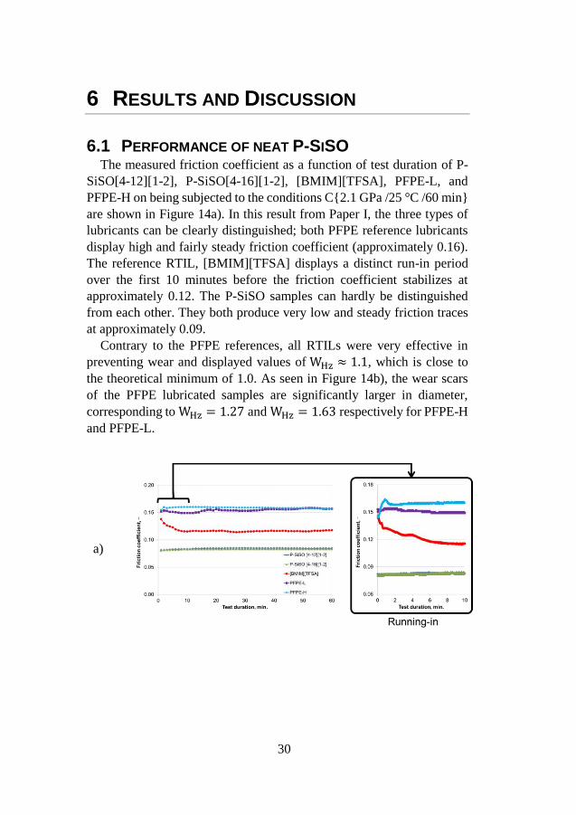
6.1 PERFORMANCE OF NEAT P-SISO The measured friction coefficient as a function of test duration of P-
SiSO[4-12][1-2], P-SiSO[4-16][1-2], [BMIM][TFSA], PFPE-L, and
PFPE-H on being subjected to the conditions C{2.1 GPa /25 °C /60 min}
are shown in Figure 14a). In this result from Paper I, the three types of
lubricants can be clearly distinguished; both PFPE reference lubricants
display high and fairly steady friction coefficient (approximately 0.16).
The reference RTIL, [BMIM][TFSA] displays a distinct run-in period
over the first 10 minutes before the friction coefficient stabilizes at
approximately 0.12. The P-SiSO samples can hardly be distinguished
from each other. They both produce very low and steady friction traces
at approximately 0.09.
Contrary to the PFPE references, all RTILs were very effective in
preventing wear and displayed values of WHz ≈ 1.1, which is close to
the theoretical minimum of 1.0. As seen in Figure 14b), the wear scars
of the PFPE lubricated samples are significantly larger in diameter,
corresponding to WHz = 1.27 and WHz = 1.63 respectively for PFPE-H
and PFPE-L.
a)
31
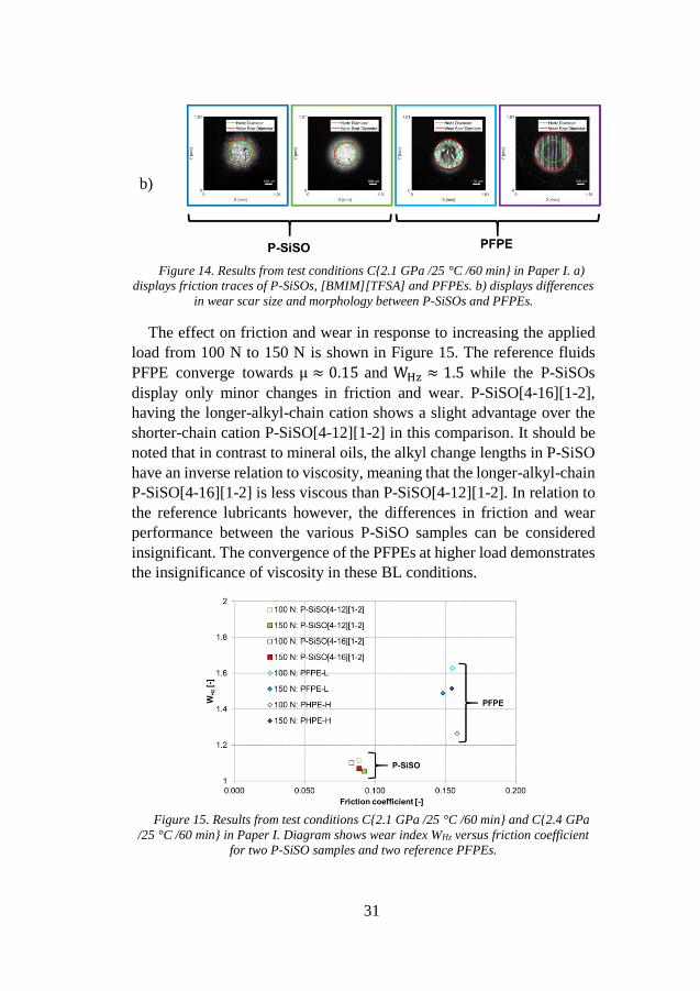
b)
Figure 14. Results from test conditions C{2.1 GPa /25 °C /60 min} in Paper I. a)
displays friction traces of P-SiSOs, [BMIM][TFSA] and PFPEs. b) displays differences
in wear scar size and morphology between P-SiSOs and PFPEs.
The effect on friction and wear in response to increasing the applied
load from 100 N to 150 N is shown in Figure 15. The reference fluids
PFPE converge towards µ ≈ 0.15 and WHz ≈ 1.5 while the P-SiSOs
display only minor changes in friction and wear. P-SiSO[4-16][1-2],
having the longer-alkyl-chain cation shows a slight advantage over the
shorter-chain cation P-SiSO[4-12][1-2] in this comparison. It should be
noted that in contrast to mineral oils, the alkyl change lengths in P-SiSO
have an inverse relation to viscosity, meaning that the longer-alkyl-chain
P-SiSO[4-16][1-2] is less viscous than P-SiSO[4-12][1-2]. In relation to
the reference lubricants however, the differences in friction and wear
performance between the various P-SiSO samples can be considered
insignificant. The convergence of the PFPEs at higher load demonstrates
the insignificance of viscosity in these BL conditions.
Figure 15. Results from test conditions C{2.1 GPa /25 °C /60 min} and C{2.4 GPa
/25 °C /60 min} in Paper I. Diagram shows wear index WHz versus friction coefficient
for two P-SiSO samples and two reference PFPEs.
32
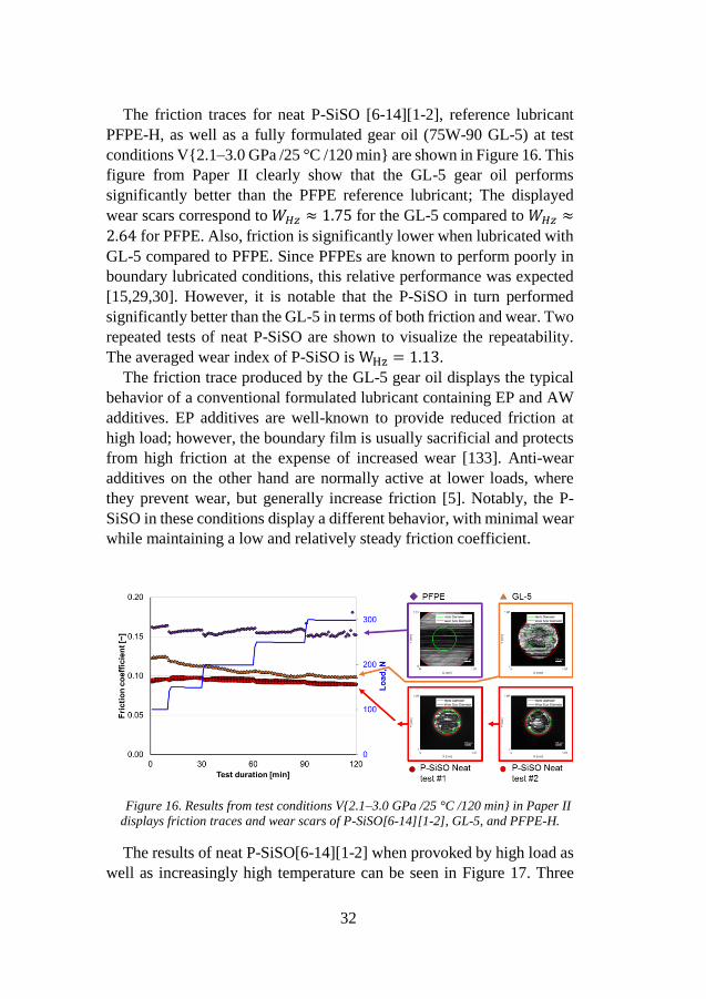
The friction traces for neat P-SiSO [6-14][1-2], reference lubricant
PFPE-H, as well as a fully formulated gear oil (75W-90 GL-5) at test
conditions V{2.1–3.0 GPa /25 °C /120 min} are shown in Figure 16. This
figure from Paper II clearly show that the GL-5 gear oil performs
significantly better than the PFPE reference lubricant; The displayed
wear scars correspond to 𝑊𝐻𝑧 ≈ 1.75 for the GL-5 compared to 𝑊𝐻𝑧 ≈
2.64 for PFPE. Also, friction is significantly lower when lubricated with
GL-5 compared to PFPE. Since PFPEs are known to perform poorly in
boundary lubricated conditions, this relative performance was expected
[15,29,30]. However, it is notable that the P-SiSO in turn performed
significantly better than the GL-5 in terms of both friction and wear. Two
repeated tests of neat P-SiSO are shown to visualize the repeatability.
The averaged wear index of P-SiSO is WHz = 1.13.
The friction trace produced by the GL-5 gear oil displays the typical
behavior of a conventional formulated lubricant containing EP and AW
additives. EP additives are well-known to provide reduced friction at
high load; however, the boundary film is usually sacrificial and protects
from high friction at the expense of increased wear [133]. Anti-wear
additives on the other hand are normally active at lower loads, where
they prevent wear, but generally increase friction [5]. Notably, the P-
SiSO in these conditions display a different behavior, with minimal wear
while maintaining a low and relatively steady friction coefficient.
Figure 16. Results from test conditions V{2.1–3.0 GPa /25 °C /120 min} in Paper II
displays friction traces and wear scars of P-SiSO[6-14][1-2], GL-5, and PFPE-H.
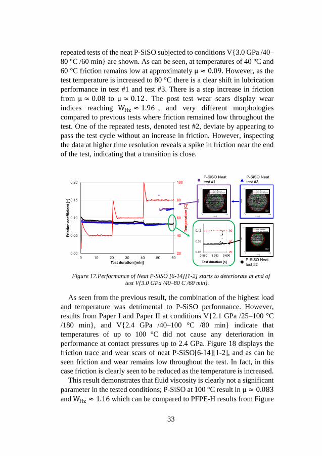
The results of neat P-SiSO[6-14][1-2] when provoked by high load as
well as increasingly high temperature can be seen in Figure 17. Three
33
repeated tests of the neat P-SiSO subjected to conditions V{3.0 GPa /40–
80 °C /60 min} are shown. As can be seen, at temperatures of 40 °C and
60 °C friction remains low at approximately µ ≈ 0.09. However, as the
test temperature is increased to 80 °C there is a clear shift in lubrication
performance in test #1 and test #3. There is a step increase in friction
from µ ≈ 0.08 to µ ≈ 0.12 . The post test wear scars display wear
indices reaching WHz ≈ 1.96 , and very different morphologies
compared to previous tests where friction remained low throughout the
test. One of the repeated tests, denoted test #2, deviate by appearing to
pass the test cycle without an increase in friction. However, inspecting
the data at higher time resolution reveals a spike in friction near the end
of the test, indicating that a transition is close.
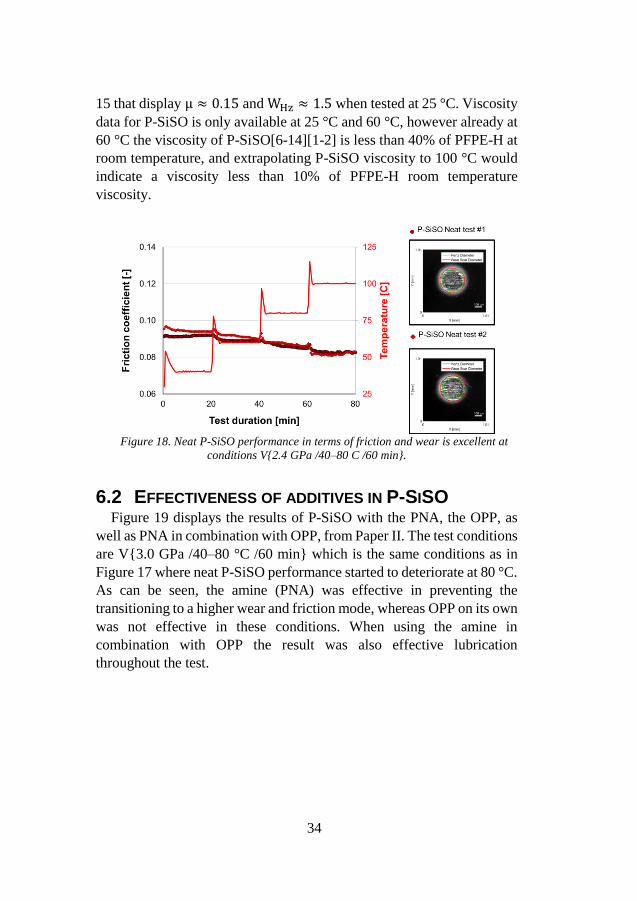
Figure 17.Performance of Neat P-SiSO [6-14][1-2] starts to deteriorate at end of
test V{3.0 GPa /40–80 C /60 min}.
As seen from the previous result, the combination of the highest load
and temperature was detrimental to P-SiSO performance. However,
results from Paper I and Paper II at conditions V{2.1 GPa /25–100 °C
/180 min}, and V{2.4 GPa /40–100 °C /80 min} indicate that
temperatures of up to 100 °C did not cause any deterioration in
performance at contact pressures up to 2.4 GPa. Figure 18 displays the
friction trace and wear scars of neat P-SiSO[6-14][1-2], and as can be
seen friction and wear remains low throughout the test. In fact, in this
case friction is clearly seen to be reduced as the temperature is increased.
This result demonstrates that fluid viscosity is clearly not a significant
parameter in the tested conditions; P-SiSO at 100 °C result in µ ≈ 0.083
and WHz ≈ 1.16 which can be compared to PFPE-H results from Figure
34
15 that display µ ≈ 0.15 and WHz ≈ 1.5 when tested at 25 °C. Viscosity
data for P-SiSO is only available at 25 °C and 60 °C, however already at
60 °C the viscosity of P-SiSO[6-14][1-2] is less than 40% of PFPE-H at
room temperature, and extrapolating P-SiSO viscosity to 100 °C would
indicate a viscosity less than 10% of PFPE-H room temperature
viscosity.
Figure 18. Neat P-SiSO performance in terms of friction and wear is excellent at
conditions V{2.4 GPa /40–80 C /60 min}.
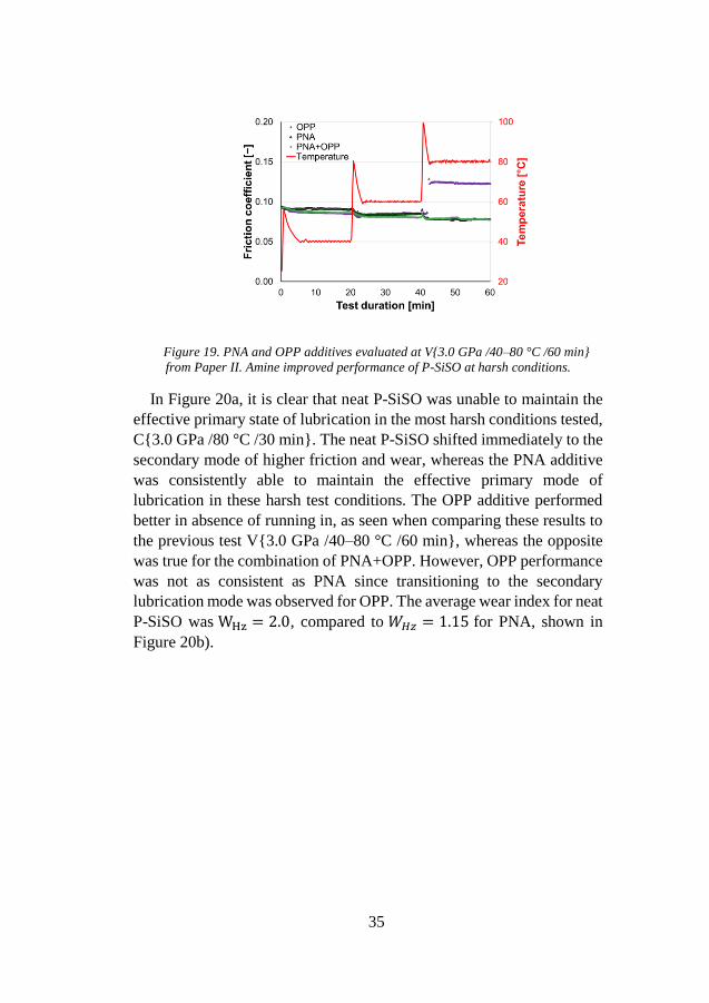
6.2 EFFECTIVENESS OF ADDITIVES IN P-SISO Figure 19 displays the results of P-SiSO with the PNA, the OPP, as
well as PNA in combination with OPP, from Paper II. The test conditions
are V{3.0 GPa /40–80 °C /60 min} which is the same conditions as in
Figure 17 where neat P-SiSO performance started to deteriorate at 80 °C.
As can be seen, the amine (PNA) was effective in preventing the
transitioning to a higher wear and friction mode, whereas OPP on its own
was not effective in these conditions. When using the amine in
combination with OPP the result was also effective lubrication
throughout the test.
35
Figure 19. PNA and OPP additives evaluated at V{3.0 GPa /40–80 °C /60 min}
from Paper II. Amine improved performance of P-SiSO at harsh conditions.
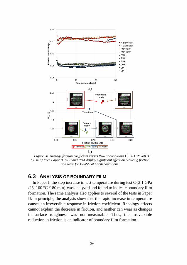
In Figure 20a, it is clear that neat P-SiSO was unable to maintain the
effective primary state of lubrication in the most harsh conditions tested,
C{3.0 GPa /80 °C /30 min}. The neat P-SiSO shifted immediately to the
secondary mode of higher friction and wear, whereas the PNA additive
was consistently able to maintain the effective primary mode of
lubrication in these harsh test conditions. The OPP additive performed
better in absence of running in, as seen when comparing these results to
the previous test V{3.0 GPa /40–80 °C /60 min}, whereas the opposite
was true for the combination of PNA+OPP. However, OPP performance
was not as consistent as PNA since transitioning to the secondary
lubrication mode was observed for OPP. The average wear index for neat
P-SiSO was WHz = 2.0, compared to 𝑊𝐻𝑧 = 1.15 for PNA, shown in
Figure 20b).
36
a)
b)
Figure 20. Average friction coefficient versus WHz at conditions C{3.0 GPa /80 °C
/30 min} from Paper II. OPP and PNA display significant effect on reducing friction
and wear for P-SiSO at harsh conditions.
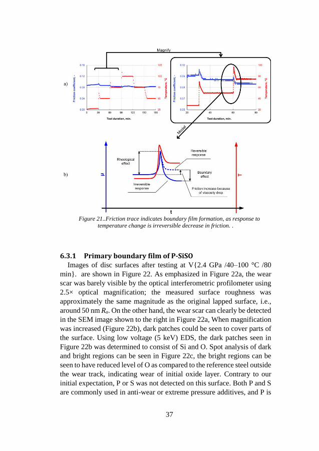
6.3 ANALYSIS OF BOUNDARY FILM In Paper I, the step increase in test temperature during test C{2.1 GPa
/25–100 °C /180 min} was analyzed and found to indicate boundary film
formation. The same analysis also applies to several of the tests in Paper
II. In principle, the analysis show that the rapid increase in temperature
causes an irreversible response in friction coefficient. Rheology effects
cannot explain the decrease in friction, and neither can wear as changes
in surface roughness was non-measurable. Thus, the irreversible
reduction in friction is an indicator of boundary film formation.
37
Figure 21..Friction trace indicates boundary film formation, as response to
temperature change is irreversible decrease in friction. .
6.3.1 Primary boundary film of P-SiSO Images of disc surfaces after testing at V{2.4 GPa /40–100 °C /80
min}. are shown in Figure 22. As emphasized in Figure 22a, the wear
scar was barely visible by the optical interferometric profilometer using
2.5× optical magnification; the measured surface roughness was
approximately the same magnitude as the original lapped surface, i.e.,
around 50 nm Ra. On the other hand, the wear scar can clearly be detected
in the SEM image shown to the right in Figure 22a, When magnification
was increased (Figure 22b), dark patches could be seen to cover parts of
the surface. Using low voltage (5 keV) EDS, the dark patches seen in
Figure 22b was determined to consist of Si and O. Spot analysis of dark
and bright regions can be seen in Figure 22c, the bright regions can be
seen to have reduced level of O as compared to the reference steel outside
the wear track, indicating wear of initial oxide layer. Contrary to our
initial expectation, P or S was not detected on this surface. Both P and S
are commonly used in anti-wear or extreme pressure additives, and P is
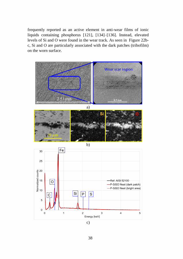
38
frequently reported as an active element in anti-wear films of ionic
liquids containing phosphorus [121], [134]–[136]. Instead, elevated
levels of Si and O were found in the wear track. As seen in Figure 22b-
c, Si and O are particularly associated with the dark patches (tribofilm)
on the worn surface.
a)
b)
c)
39
Figure 22. Surface analysis of worn discs lubricated by neat P-SiSO at V{2.4 GPa
/40–100 °C /80 min}. a) image of wear scar region from optical profiler and SEM. b)
EDS mapping showing dark patch corresponding to Si+O. c) EDS spectra showing
difference between dark and bright regions.
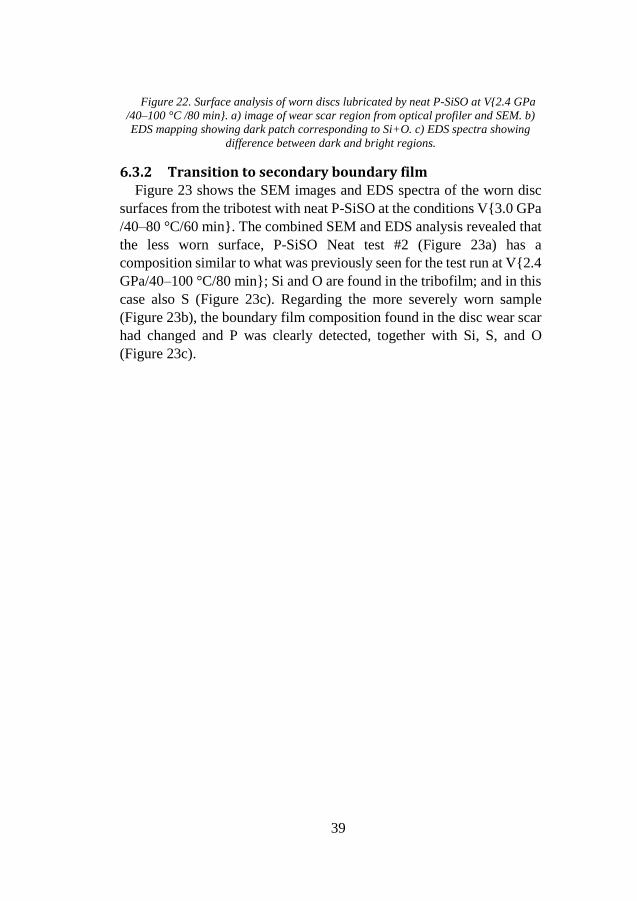
6.3.2 Transition to secondary boundary film Figure 23 shows the SEM images and EDS spectra of the worn disc
surfaces from the tribotest with neat P-SiSO at the conditions V{3.0 GPa
/40–80 °C/60 min}. The combined SEM and EDS analysis revealed that
the less worn surface, P-SiSO Neat test #2 (Figure 23a) has a
composition similar to what was previously seen for the test run at V{2.4
GPa/40–100 °C/80 min}; Si and O are found in the tribofilm; and in this
case also S (Figure 23c). Regarding the more severely worn sample
(Figure 23b), the boundary film composition found in the disc wear scar
had changed and P was clearly detected, together with Si, S, and O
(Figure 23c).
40
a)
b)
c)
Figure 23.Surface analysis of worn discs lubricated by neat P-SiSO at conditions
V{3.0 GPa/40–80 °C/60 min}. SEM images of disc in primary a) and secondary b)
lubrication mode. c) EDS spectra showing relating boundary film composition to
lubrication mode.
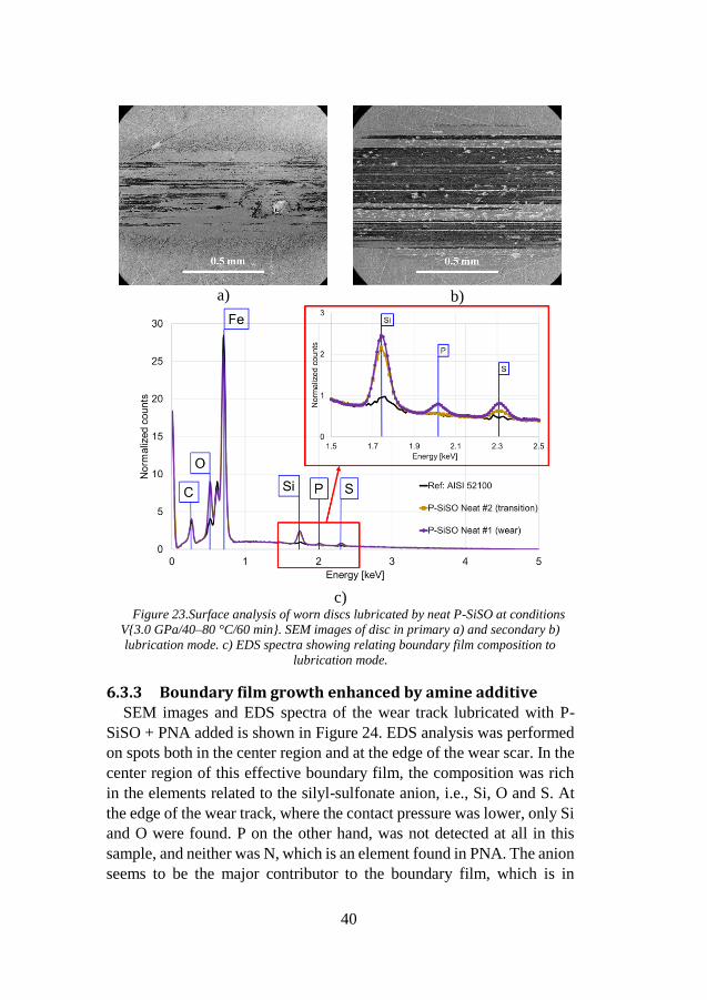
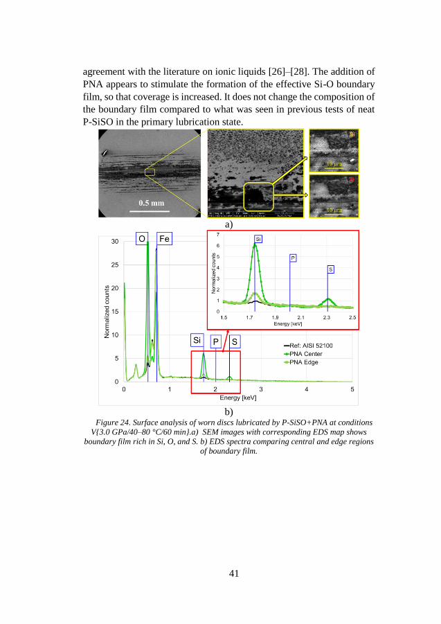
6.3.3 Boundary film growth enhanced by amine additive SEM images and EDS spectra of the wear track lubricated with P-
SiSO + PNA added is shown in Figure 24. EDS analysis was performed
on spots both in the center region and at the edge of the wear scar. In the
center region of this effective boundary film, the composition was rich
in the elements related to the silyl-sulfonate anion, i.e., Si, O and S. At
the edge of the wear track, where the contact pressure was lower, only Si
and O were found. P on the other hand, was not detected at all in this
sample, and neither was N, which is an element found in PNA. The anion
seems to be the major contributor to the boundary film, which is in
41
agreement with the literature on ionic liquids [26]–[28]. The addition of
PNA appears to stimulate the formation of the effective Si-O boundary
film, so that coverage is increased. It does not change the composition of
the boundary film compared to what was seen in previous tests of neat
P-SiSO in the primary lubrication state.
a)
b)
Figure 24. Surface analysis of worn discs lubricated by P-SiSO+PNA at conditions
V{3.0 GPa/40–80 °C/60 min}.a) SEM images with corresponding EDS map shows
boundary film rich in Si, O, and S. b) EDS spectra comparing central and edge regions
of boundary film.
42
7 SUMMARY AND OUTLOOK
The hydrocarbon-mimicking ionic liquid P-SiSO forms highly
effective boundary films that provide low friction while maintaining low
wear in the conditions tested. These boundary films are unexpectedly
composed of the elements Si and O. The formation of this boundary film
can be stimulated by the addition of an amine additive, so that the
coverage of the film increases. At sufficiently harsh conditions, the P-
SiSO primary boundary film (composed of Si+O) breaks down and
transitions to secondary boundary film that includes P, as well as Si, S
and O. The secondary boundary film, although much less effective than
the primary, provides significantly lower friction and wear than the
reference PFPE.
P-SiSO provides excellent performance in the conditions evaluated,
which demonstrates the feasibility of improving boundary lubricating
properties of ionic liquids through molecular design. The formation of
silicate type boundary film is a serendipitous finding, as P and S were
expected to be the elements of most importance to boundary film
formation.
It should be noted that a silicate boundary film on its own does not
explain the simultaneously low friction and wear that was observed. One
hypothesis for the mechanism responsible for this result is the formation
of a hybrid type boundary film. In this hypothesis, the silicate boundary
film would provide hardness and wear protection, while another
mechanism is responsible for reducing friction. Two possible
mechanisms that can explain the reduced friction are; either structured
layers of adsorbed IL could provide the easily sheared layer that reduces
friction, or the higher alkyl group of the cation acts in a manner similar
to traditional friction modifier additives.
The tribological testing described in this thesis was performed with
AISI 52100 steel in air environment in order to comply with the stepwise
approach. However, representative environment and materials should be
incorporated in future work. Predicting the interaction between fluid,
environment, and material is challenging. It is likely that the accuracy of
such predictions could be improved by employing computational tools
to evaluate carefully considered hypothesis.
43
8 REFERENCES
[1] E. Nyberg, C. Y. Respatiningsih, and I. Minami, “Molecular
design of advanced lubricant base fluids: hydrocarbon-
mimicking ionic liquids,” RSC Adv., vol. 7, no. 11, pp. 6364–
6373, 2017.
[2] E. Nyberg, J. Mouzon, M. Grahn, and I. Minami, “Formation of
Boundary Film from Ionic Liquids Enhanced by Additives,”
Appl. Sci., vol. 7, no. 5, p. 433, 2017.
[3] B. J. Hamrock, S. R. Schmid, and B. Jacobson, Fundamentals of
fluid film lubrication. New York: Marcel Dekker, 2004.
[4] Y. Wang and Q. J. Wang, “Lubrication Regimes,” in
Encyclopedia of Tribology, Q. J. Wang and Y.-W. Chung, Eds.
Boston, MA: Springer US, 2013, pp. 2110–2113.
[5] H. Spikes, “The History and Mechanisms of ZDDP,” Tribol.
Lett., vol. 17, no. 3, pp. 469–489, 2004.
[6] H. Spikes, “Friction Modifier Additives,” Tribol. Lett., vol. 60,
no. 1, pp. 1–26, 2015.
[7] L. R. Rudnick, Lubricant additives : chemistry and applications.
New York: Marcel Dekker, 2003.
[8] European Space Agency, “Exploring Together: ESA Space
Exploration Strategy,” Noordwijk, the Netherlands, 2015.
[9] International Space Exploration Coordination Group (ISECG),
“The Global Exploration Roadmap,” 2013.
[10] 115th Congress of U.S.A., National Aeronautics and Space
Administration Transition Authorization Act of 2017.
Washington, D.C., 2017, pp. 1–78.
[11] National Research Council, “Pathways to exploration: rationales
and approaches for a US program of human space exploration,”
National Academies Press, Washington, D.C., 2014.
[12] National Aeronautics and Space Administration, “NASA’s
Journey to Mars: Pioneering Next Steps in Space Exploration,”
2015.
[13] National Research Council, “Vision and Voyages for Planetary
Science in the Decade 2013-2022,” Washington, D.C., 2011.
[14] S. V Didziulis, Tribochemistry in Space Lubrication. Boston,
MA: Springer US, 2013.
[15] D. H. Buckley, “Friction, Wear and Lubrication in Vacuum,”
NASA STI, 1972.
[16] E. W. Roberts, “Space tribology: its role in spacecraft
mechanisms,” J. Phys. D. Appl. Phys., vol. 45, no. 50, p.
44
503001, 2012.
[17] W. R. Jones and M. J. Jansen, “Tribology for space
applications,” Proc. Inst. Mech. Eng. Part J J. Eng. Tribol., vol.
222, no. 8, pp. 997–1004, 2008.
[18] R. Fleischner, “Insight instrument deployment arm,” Conf.
Proc. 15th Eur. Sp. Mech. Tribol. Symp., no. 1, 2013.
[19] K. Novak, Y. Liu, C.-J. Lee, and S. Hendricks, “Mars Science
Laboratory Rover Actuator Thermal Design,” in 40th
International Conference on Environmental Systems, 2010, pp.
1–11.
[20] P. Poulakis, J. L. Vago, D. Loizeau, C. Vicente-Arevalo, A.
Hutton, R. Mccoubrey, J. Arnedo-Rodriguez, J. Smith, B.
Boyes, S. Jessen, A. Otero-Rubio, S. Durrant, G. Gould, L.
Joudrier, Y. Yushtein, C. Alary, E. Zekri, P. Baglioni, A.
Cernusco, F. Maggioni, R. Yague, and F. Ravera, “Overview
and Development Status of the ExoMars Rover Mobility
Subsystem,” ASTRA 2015 - 13th ESA Work. Adv. Sp. Technol.
Robot. Autom., no. MAY 2015, 2015.
[21] N. Silva, R. Lancaster, and J. Clemmet, “ExoMars Rover
Vehicle Mobility Functional Architecture and Key Design
Drivers,” ASTRA Conf. 2013, no. 1, 2013.
[22] R. Mccoubrey, J. Smith, A. Cernusco, and S. Durrant,
“ExoMars Suspension and Locomotion,” iSAIRAS 2014, pp. 4–
7, 2014.
[23] K. S. Novak, J. G. Kempenaar, M. Redmond, and P. Bhandari,
“Preliminary Surface Thermal Design of the Mars 2020 Rover.”
45th International Conference on Environmental Systems, 01-
Jul-2015.
[24] ASTM International, “Standard Test Method for Total Mass
Loss and Collected Volatile Condensable Materials from
Outgassing in a Vacuum Environment (E595-15).” ASTM
International, 2015.
[25] C. Ye, W. Liu, Y. Chen, and L. Yu, “Room-temperature ionic
liquids: a novel versatile lubricant.,” Chem. Commun., no. 21,
pp. 2244–2245, 2001.
[26] I. Minami, “Ionic liquids in tribology,” Molecules, vol. 14, no.
6, pp. 2286–2305, 2009.
[27] M. D. Bermúdez, A. E. Jiménez, J. Sanes, and F. J. Carrión,
“Ionic liquids as advanced lubricant fluids,” Molecules, vol. 14,
no. 8, pp. 2888–2908, 2009.
[28] A. E. Somers, P. C. Howlett, D. R. MacFarlane, and M. Forsyth,
“A Review of Ionic Liquid Lubricants,” Lubricants, vol. 1, no.
45
1, pp. 3–21, 2013.
[29] D. Dowson, History of tribology, 2. ed. London: Professional
Engineering Publishing, 1998.
[30] J. E. Quibell, “Tomb of Yuaa and Thuiu.” Le Caire: Impr. de
l’Institut français d’archéologie orientale, Cairo, Egypt, p. 228,
1908.
[31] B. Bhushan, Modern tribology handbook. Vol. 1, Principles of
tribology. Boca Raton, Fla.: CRC Press, 2001.
[32] K. Carnes, “The Ten Greatest Events in Tribology History,”
Tribology & Lubrication Technology, no. June, pp. 38–47,
2005.
[33] B. Tower, “First report on friction experiments,” Proc. Inst.
Mech. Eng., vol. 34, no. 1, pp. 632–659, 1883.
[34] O. Reynolds, “On the Theory of Lubrication and Its Application
to Mr. Beauchamp Tower’s Experiments, Including an
Experimental Determination of the Viscosity of Olive Oil.,”
Proc. R. Soc. London, vol. 40, no. 242–245, pp. 191–203, 1886.
[35] Y. Wang and Q. J. Wang, “Stribeck Curves,” in Encyclopedia of
Tribology, Q. J. Wang and Y.-W. Chung, Eds. Boston, MA:
Springer US, 2013, pp. 3365–3370.
[36] W. B. Hardy and I. Doubleday, “Boundary Lubrication. The
Paraffin Series,” Proc. R. Soc. London. Ser. A, Contain. Pap. a
Math. Phys. Character, vol. 100, no. 707, pp. 550–574, 1922.
[37] W. B. Hardy and I. Doubleday, “Boundary Lubrication. The
Temperature Coefficient,” Proc. R. Soc. London. Ser. A,
Contain. Pap. a Math. Phys. Character, vol. 101, no. 713, pp.
487–492, 1922.
[38] H. Spikes, “The History and Mechanisms of ZDDP,” Tribol.
Lett., vol. 17, no. 3, pp. 469–489, 2004.
[39] F. P. Bowden and D. Tabor, The friction and lubrication of
solids. Oxford: Clarendon, 1986.
[40] F. P. Bowden and D. Tabor, “Friction, lubrication and wear: a
survey of work during the last decade,” Br. J. Appl. Phys., vol.
17, pp. 1521–1544, 1966.
[41] H. P. Jost, “Lubrication (Tribology) education and research A
Report on the Present Position and Industry’s Needs,” 1966.
[42] A. Stevenson, “friction,” Oxford Dictionary of English. Oxford
University Press, 2010.
[43] A. Martini, “Friction and Friction Reduction Technologies for
Mixed EHL,” in Encyclopedia of Tribology, Q. J. Wang and Y.-
W. Chung, Eds. Boston, MA: Springer US, 2013, pp. 1285–
1287.
46
[44] P. J. Blau, “Amontons’ Laws of Friction,” in Encyclopedia of
Tribology, Q. J. Wang and Y.-W. Chung, Eds. Boston, MA:
Springer US, 2013, p. 71.
[45] “ASTM Standard G40-15: Standard Terminology Relating to
Wear and Erosion,” Annu. B. ASTM Stand., pp. 1–9, 2015.
[46] I. Minami, “Molecular Science of Lubricant Additives,” Appl.
Sci., vol. 7, no. 5, p. 445, 2017.
[47] S. M. Hsu and R. S. Gates, “Boundary lubricating films:
Formation and lubrication mechanism,” Tribol. Int., vol. 38, no.
3, pp. 305–312, 2005.
[48] W. J. Anderson and D. C. Glenn, “The Effect of the Space
Environment on Lubricants and Rolling Element Bearings,”
NASA STI, 1967.
[49] E. V. Zaretsky, “Liquid lubrication in space,” Tribol. Int., vol.
23, no. 2, pp. 75–93, Apr. 1990.
[50] C. Gurrisi, R. Seidel, S. Dickerson, S. Didziulis, P. Frantz, and
K. Ferguson, “Space Station Control Moment Gyroscope
Lessons Learned,” Proc. 40th Aerosp. Mech. Symp., pp. 161–
176, 2010.
[51] R. R. Burt and R. W. Loffi, “Failure Analysis of International
Space Station Control Moment Gyro,” in European Space
Agency, (Special Publication) ESA SP, 2003, no. 524, pp. 13–
25.
[52] E. P. Harik, J. Mcfatter, D. J. Sweeney, C. F. Enriquez, D. M.
Taylor, and D. S. Mccann, “The International Space Station
Solar Alpha Rotary Joint Anomaly Investigation,” Proc. 40th
Aerosp. Mech. Symp., pp. 187–206, 2010.
[53] C. Dellacorte, T. L. Krantz, and M. J. Dube, “ISS Solar Array
Alpha Rotary Joint (SARJ) Bearing Failure and Recovery:
Technical and Project Management Lessons Learned,” NASA
STI, no. 2011–217116, pp. 1–25, 2011.
[54] M. C. Wright, V. L. Long, and S. J. McDanels, “The evolution
of failure analysis at NASA’s Kennedy Space Center and
lessons learned,” Handb. Mater. Fail. Anal. with Case Stud.
from Aerosp. Automot. Ind., pp. 57–73, 2015.
[55] M. Tafazoli, “A study of on-orbit spacecraft failures,” Acta
Astronaut., vol. 64, no. 2–3, pp. 195–205, 2009.
[56] M. R. Johnson, “The Galileo High Antenna Deployment
Anomaly,” 28th Aerosp. Mech. Symp., vol. 28, pp. 359–377,
1994.
[57] K. Miyoshi, “Aerospace Mechanisms and Tribology
Technology: Case Studies,” NASA STI, 1999.
47
[58] M. Mizukami and B. Nakazono, “Dawn Spacecraft Reaction
Control System Flight Experience,” in 50th
AIAA/ASME/SAE/ASEE Joint Propulsion Conference, American
Institute of Aeronautics and Astronautics, 2014.
[59] R. Cowen, “The wheels come off Kepler,” Nature, vol. 497, no.
7450, pp. 417–8, 2013.
[60] M. Mojarradi, T. R. Tyler, P. B. Abel, and G. Levanas, “Electro-
Mechanical Systems for Extreme Space Environments,” in 36th
Annual Government Microcircuit Applications & Critical
Technologies Conference, 2011.
[61] T. Tyler, G. Levanas, M. Mojarradi, and P. Abel, “Development
and Testing of Mechanism Technology for Space Exploration in
Extreme Environments,” in ESMATS - 14th European Space
Mechanisms and Tribology Symposium, 2011.
[62] D. Oberhettinger, “Sweater Weather on Mars: The MSL
Actuator Design Process Escape,” Pasadena, CA, 2014.
[63] R. Billing and R. Fleischner, “Mars Science Laboratory Robotic
Arm,” ESMATS - Eur. Sp. Mech. Tribol. Symp., no. September,
pp. 28–30, 2011.
[64] R. L. Fusaro, “Lubrication of space systems,” Lubr. Eng., no.
March, 1995.
[65] J. Jones, William R, B. A. Shogrin, and M. J. Jansen, “Research
on Liquid Lubricants for Space Mechanisms,” NASA STI, 1999.
[66] J. Jones, William R and M. J. Jansen, “Space Tribology,” NASA
STI, 2000.
[67] R. L. Fusaro and M. M. Khonsari, “Liquid lubrication for space
applications,” NASA STI, no. January, 1993.
[68] W. H. Gumprecht, “PR-143—A New Class of High-
Temperature Fluids,” A S L E Trans., vol. 9, no. 1, pp. 24–30,
1966.
[69] P. L. Conley and J. J. Bohner, “Experience With Synthetic
Fluorinated Lubricants,” in 24th Aerospace Mechanisms
Symposium, 1990, pp. 213–230.
[70] W. R. Jones, “Properties of Perfluoropolyethers for Space
Applications,” Tribol. Trans., vol. 38, no. 3, pp. 557–564, 1995.
[71] D. J. Carré and J. A. Markowitz, “The Reaction of
Perfluoropolyalkylether Oil with FeF3, AlF3, and AlCl3 at
Elevated Temperatures,” ASLE Trans., vol. 28, no. 1, pp. 40–46,
1985.
[72] D. J. Carré, “Perfluoropolyalkylether Oil Degradation: Inference
of FeF3 Formation on Steel Surfaces under Boundary
Conditions,” ASLE Trans., vol. 29, no. 2, pp. 121–125, 1986.
48
[73] M. Buttery, L. Gaillard, S. Rajala, E. Roberts, T. Rohr, and a.
Merstallinger, “Fomblin Z25 : a New Method for Its
Degradation Assessment & Proposal for Safe Operation in
Space,” Conf. Proc. 15th Eur. Sp. Mech. Tribol. Symp., no.
September, pp. 25–27, 2013.
[74] O. O. Ajayi, A. J. Goodell, and L. D. Wedeven, “Enhancement
of Perfluoropolyether Boundary Lubrication Performance I .
Preliminary Results,” NASA STI, 1996.
[75] A. Shogrin, W. R. Jones Jr, P. Herrera-Fierro, T.-Y. Lin, and H.
Kawa, “Evaluation of Boundary-Enhancement Additives for
Perfluoropolyethers,” NASA STI, 1997.
[76] G. Huang, Q. Yu, Z. Ma, M. Cai, F. Zhou, and W. Liu,
“Fluorinated Candle Soot as the Lubricant Additive of
Perfluoropolyether,” Tribol. Lett., vol. 65, no. 1, p. 28, Mar.
2017.
[77] C. G. Venier, E. W. Casserly, and S. Gunsel, “Tris(2-
Octyldodecyl)Cyclopentane, a Low Volatility, Wide Liquid
Range, Hydrocarbon Fluid,” J. Synth. Lubr., pp. 237–252, 1992.
[78] S. C. Peterangelo, L. J. Gschwender, C. E. Snyder Jr., J. Jones,
William R, Q. N. Nguyen, and M. J. Jansen, “Improved
additives for multiply alkylated cyclopentane-based lubricants,”
J. Synth. Lubr., vol. 25, pp. 31–41, 2008.
[79] X. Fan, L. Wang, W. Li, and S. Wan, “Improving Tribological
Properties of Multialkylated Cyclopentanes under Simulated
Space Environment: Two Feasible Approaches,” ACS Appl.
Mater. Interfaces, vol. 7, no. 26, pp. 14359–14368, Jul. 2015.
[80] Z. Song, Y. Liang, M. Fan, F. Zhou, and W. Liu, “Lithium-
based ionic liquids as novel lubricant additives for multiply
alkylated cyclopentanes (MACs),” Friction, vol. 1, no. 3, pp.
222–231, 2013.
[81] M. Marchetti, M. H. Meurisse, P. Vergne, J. Sicre, and M.
Durand, “Analysis of oil supply phenomena by sintered porous
reservoirs,” Tribol. Lett., vol. 10, no. 3, pp. 163–170, 2001.
[82] V. I. Moroz, “The atmosphere of Mars,” Space Sci. Rev., vol.
19, no. 6, pp. 763–843, Dec. 1976.
[83] G. M. Martínez, C. N. Newman, A. De Vicente-Retortillo, E.
Fischer, N. O. Renno, M. I. Richardson, A. G. Fairén, M.
Genzer, S. D. Guzewich, R. M. Haberle, A.-M. Harri, O.
Kemppinen, M. T. Lemmon, M. D. Smith, M. de la Torre-
Juárez, and A. R. Vasavada, “The Modern Near-Surface
Martian Climate: A Review of In-situ Meteorological Data from
Viking to Curiosity,” Space Sci. Rev., Apr. 2017.
49
[84] G. Y. Lee and J. A. Donaldson, “Dreaming on Mars: How
Curiosity performs actuator warm-up while sleeping,” Proc.
2013 8th Int. Conf. Syst. Syst. Eng. SoSE Cloud Comput. Emerg.
Inf. Technol. Appl. SoSE 2013, pp. 123–128, 2013.
[85] H. J. Eisen, C. W. Buck, G. R. Gillis-Smith, and J. W. Umland,
“Mechanical design of the Mars Pathfinder mission,” in 7th
European Space Mechanisms and Tribology Symposium, 1997,
pp. 293–301.
[86] R. Fleischner, “Concurrent actuator development for the mars
exploration rover instrument deployment device,” Eur. Sp.
Agency, (Special Publ. ESA SP, no. 524, pp. 255–262, 2003.
[87] R. Phillips, M. Palladino, and C. Courtois, “Development of
Brushed and Brushless DC Motors for use in the ExoMars
Drilling and Sampling Mechanism,” Aerosp. Mech. Symp., pp.
1–15, 2012.
[88] H. Schultheiss, T. Tobie, and K. Stahl, “The Wear Behavior of
Small Module Gears Lubricated with NLGI 1 Grease,” Tribol.
Trans., vol. 0, no. 0, pp. 1–9, 2017.
[89] D. F. Salmon, “Turbulent Heat Transfer from a Molten Fluoride
Salt mixture to Sodium-Potassium Alloy in a Double-tube Heat
Exchanger,” Oak Ridge, TN (United States), 1954.
[90] H. W. Hoffman, “Molten Salt Heat Transfer,” Oak Ridge Natl.
Lab. Reports, vol. CF 58-2-40, 1958.
[91] P. G. Smith, “High-Temperature Molten-Salt Lubricated
Hydrodynamic Journal Bearings,” ASLE Trans., vol. 4, no. 2,
pp. 263–274, 1961.
[92] J. S. Wilkes, “A short history of ionic liquids—from molten
salts to neoteric solvents,” Green Chem., vol. 4, no. 2, pp. 73–
80, 2002.
[93] R. Hayes, G. G. Warr, and R. Atkin, “Structure and
Nanostructure in Ionic Liquids,” Chem. Rev., p.
150601082109009, 2015.
[94] J. D. Holbrey and K. R. Seddon, “Ionic Liquids,” Clean
Technol. Environ. Policy, vol. 1, no. 4, pp. 223–236, Dec. 1999.
[95] M. Freemantle, “Ionic liquids prove increasingly versatile,”
Chem. Eng. News Arch., vol. 77, no. 1, pp. 23–24, Jan. 1999.
[96] M. J. Earle and K. R. Seddon, “Ionic liquids. Green solvents for
the future,” Pure Appl. Chem., vol. 72, no. 7, pp. 1391–1398,
2000.
[97] R. D. Rogers and K. R. Seddon, “Ionic Liquids - Solvents of the
Future?,” Science (80-. )., vol. 302, no. 5646, pp. 792–793,
2003.
50
[98] C. M. Gordon and M. J. Muldoon, “Synthesis and Purification,”
in Ionic Liquids in Synthesis, Second., vol. 1, no. 2, P.
Wasserscheid and T. Welton, Eds. Weinheim: WILEY‐VCH
Verlag, 2008, pp. 7–53.
[99] M. Palacio and B. Bhushan, “A Review of Ionic Liquids for
Green Molecular Lubrication in Nanotechnology,” Tribol. Lett.,
vol. 40, no. 2, pp. 247–268, 2010.
[100] I. Minami, “Ionic Liquid Lubricants,” in Encyclopedia of
Tribology, Q. J. Wang and Y.-W. Chung, Eds. Boston, MA:
Springer US, 2013, pp. 1859–1866.
[101] S. Keskin, D. Kayrak-Talay, U. Akman, and Ö. Hortaçsu, “A
review of ionic liquids towards supercritical fluid applications,”
J. Supercrit. Fluids, vol. 43, no. 1, pp. 150–180, 2007.
[102] A. E. Jiménez, M. D. Bermúdez, F. J. Carrión, and G. Martínez-
Nicolás, “Room temperature ionic liquids as lubricant additives
in steel–aluminium contacts: Influence of sliding velocity,
normal load and temperature,” Wear, vol. 261, no. 3–4, pp. 347–
359, 2006.
[103] A. E. Jiménez, M. D. Bermúdez, P. Iglesias, F. J. Carrión, and
G. Martínez-Nicolás, “1-N-alkyl -3-methylimidazolium ionic
liquids as neat lubricants and lubricant additives in steel–
aluminium contacts,” Wear, vol. 260, no. 7–8, pp. 766–782,
2006.
[104] Y. Kondo, S. Yagi, T. Koyama, R. Tsuboi, and S. Sasaki,
“Lubricity and corrosiveness of ionic liquids for steel-on-steel
sliding contacts,” Proc. Inst. Mech. Eng. Part J J. Eng. Tribol.,
vol. 226, no. 11, pp. 991–1006, 2012.
[105] X. Liu, F. Zhou, Y. Liang, and W. Liu, “Benzotriazole as the
additive for ionic liquid lubricant: one pathway towards actual
application of ionic liquids,” Tribol. Lett., vol. 23, no. 3, pp.
191–196, 2006.
[106] B. Yu, F. Zhou, C. Pang, B. Wang, Y. Liang, and W. Liu,
“Tribological evaluation of α, ω-diimidazoliumalkylene
hexafluorophosphate ionic liquid and benzotriazole as additive,”
Tribol. Int., vol. 41, no. 8, pp. 797–801, 2008.
[107] I. Minami, T. Inada, and Y. Okada, “Tribological properties of
halogen-free ionic liquids,” Proc. Inst. Mech. Eng. Part J J.
Eng. Tribol., vol. 226, no. 11, pp. 891–902, 2012.
[108] L. Zhang, D. Feng, and B. Xu, “Tribological characteristics of
alkylimidazolium diethyl phosphates ionic liquids as lubricants
for steel-steel contact,” Tribol. Lett., vol. 34, no. 2, pp. 95–101,
2009.
51
[109] R. M. Mortier, M. F. Fox, and S. T. Orszulik, Chemistry and
Technology of Lubricants, 3rd ed., vol. 3. London New York:
Springer Dordrecht Heidelberg, 2010.
[110] B. L. Papke, “Mineral Oil Base Fluids,” in Encyclopedia of
Tribology, Q. J. Wang and Y.-W. Chung, Eds. Boston, MA:
Springer US, 2013, pp. 2257–2261.
[111] E. S. Forbes, “The load-carrying action of organo-sulphur
compounds - A review,” Wear, vol. 15, no. 2, pp. 87–96, 1970.
[112] E. S. Forbes, “Antiwear and extreme pressure additives for
lubricants,” Tribology, vol. 3, no. 3, pp. 145–152, Aug. 1970.
[113] C. McFadden, C. Soto, and N. Spencer, “Adsorption and surface
chemistry in tribology,” Tribol. Int., vol. 30, no. 12, pp. 881–
888, 1997.
[114] A. J. Gellman and N. D. Spencer, “Surface chemistry in
tribology,” Proc. Inst. Mech. Eng. Part J J. Eng. Tribol., vol.
216, no. 6, pp. 443–461, Jan. 2002.
[115] A. P. Parsaeian, A. Ghanbarzadeh, C. P. Marcel, V. Eijk, I.
Nedelcu, A. Neville, and A. Morina, “A New Insight into the
Interfacial Mechanisms Involved in the Formation of Tribofilm
by Zinc Dialkyl Dithiophosphate,” Appl. Surf. Sci., vol. 403, pp.
472–486, 2017.
[116] X. He and S. H. Kim, “Mechanochemistry of physisorbed
molecules at tribological interfaces: Molecular structure
dependence of tribochemical polymerization (submitted),”
Langmuir, 2016.
[117] J. Zhang and H. Spikes, “On the Mechanism of ZDDP Antiwear
Film Formation,” Tribol. Lett., vol. 63, no. 2, pp. 1–15, 2016.
[118] I. Minami, N. Watanabe, H. Nanao, S. Mori, K. Fukumoto, and
H. Ohno, “Improvement in the tribological properties of
imidazolium-derived ionic liquids by additive technology,” J.
Synth. Lubr., vol. 25, no. 2, pp. 45–55, Apr. 2008.
[119] I. Minami, “Development of novel lubricity additives :
hydroxyalkyl ester of ortho-phenylene phosphate,” vol. 1, pp.
139–146, 1995.
[120] I. Minami and S. Mori, “Concept of molecular design towards
additive technology for advanced lubricants,” Lubr. Sci., vol.
19, no. 2, pp. 127–149, 2007.
[121] I. Minami, T. Inada, R. Sasaki, and H. Nanao, “Tribo-Chemistry
of Phosphonium-Derived Ionic Liquids,” Tribol. Lett., vol. 40,
no. 2, pp. 225–235, 2010.
[122] V. Totolin, I. Minami, C. Gabler, J. Brenner, and N. Dörr,
“Lubrication Mechanism of Phosphonium Phosphate Ionic
52
Liquid Additive in Alkylborane–Imidazole Complexes,” Tribol.
Lett., vol. 53, no. 2, pp. 421–432, 2014.
[123] L. Pisarova, V. Totolin, C. Gabler, N. Dörr, E. Pittenauer, G.
Allmaier, and I. Minami, “Insight into degradation of
ammonium-based ionic liquids and comparison of tribological
performance between selected intact and altered ionic liquid,”
Tribol. Int., vol. 65, pp. 13–27, 2013.
[124] A. E. Somers, R. Yunis, M. B. Armand, J. M. Pringle, D. R.
MacFarlane, and M. Forsyth, “Towards Phosphorus Free Ionic
Liquid Anti-Wear Lubricant Additives,” Lubricants, vol. 4, no.
22, pp. 1–12, Jun. 2016.
[125] A. E. Somers, B. Khemchandani, P. C. Howlett, J. Sun, D. R.
MacFarlane, and M. Forsyth, “Ionic liquids as antiwear
additives in base oils: Influence of structure on miscibility and
antiwear performance for steel on aluminum,” ACS Appl. Mater.
Interfaces, vol. 5, pp. 11544–11553, 2013.
[126] C. E. Snyder Jr., L. J. Gschwender, C. Tamborski, G. J. Chen,
and D. R. Anderson, “Synthesis and Characterization of
Silahydrocarbons — A Class of Thermally Stable Wide-Liquid-
Range Functional Fluids,” ASLE Trans., vol. 25, no. 3, pp. 299–
308, 1982.
[127] I. Minami, S. Kikuta, and H. Okabe, “Anti-wear and friction
reducing additives composed of ortho-phenylene phosphate-
amine salts for polyether type base stocks,” Tribol. Int., vol. 31,
no. 6, pp. 305–312, 1998.
[128] Q. J. Wang and D. Zhu, “Hertz Theory: Contact of Ellipsoidal
Surfaces,” in Encyclopedia of Tribology, Q. J. Wang and Y.-W.
Chung, Eds. Boston, MA: Springer US, 2013, pp. 1647–1654.
[129] R. C. Watkins, “The use of the hertzian dimension in wear scar
analyses (application to four-ball results),” Wear, vol. 91, no. 3,
pp. 349–354, 1983.
[130] M. Kalin and J. Vižintin, “Use of equations for wear volume
determination in fretting experiments,” Wear, vol. 237, no. 1,
pp. 39–48, 2000.
[131] L. Zhu, L. Chen, X. Yang, and H. Song, “Functionalized Ionic
Liquids as Lubricants for Steel-Steel Contact,” Appl. Mech.
Mater., vol. Vols. 138-, pp. 630–634, 2012.
[132] D. Jiang, L. Hu, and D. Feng, “Crown-type ionic liquids as
lubricants for steel-on-steel system,” Tribol. Lett., vol. 41, no. 2,
pp. 417–424, 2011.
[133] T. Sakamoto, H. Uetz, J. Föhl, and M. A. Khosrawi, “The
reaction layer formed on steel by additives based on sulphur and
53
phosphorus compounds under conditions of boundary
lubrication,” Wear, vol. 77, no. 2, pp. 139–157, Apr. 1982.
[134] X. Liu, F. Zhou, Y. Liang, and W. Liu, “Tribological
performance of phosphonium based ionic liquids for an
aluminum-on-steel system and opinions on lubrication
mechanism,” Wear, vol. 261, no. 10, pp. 1174–1179, 2006.
[135] L. J. Weng, X. Q. Liu, Y. M. Liang, and Q. J. Xue, “Effect of
tetraalkylphosphonium based ionic liquids as lubricants on the
tribological performance of a steel-on-steel system,” Tribol.
Lett., vol. 26, no. 1, pp. 11–17, 2007.
[136] Z. Mu, F. Zhou, S. Zhang, Y. Liang, and W. Liu, “Effect of the
functional groups in ionic liquid molecules on the friction and
wear behavior of aluminum alloy in lubricated aluminum-on-
steel contact,” Tribol. Int., vol. 38, no. 8, pp. 725–731, 2005.

54
APPENDED PAPERS
55
PAPER I
MOLECULAR DESIGN OF ADVANCED LUBRICANT BASE
FLUIDS: HYDROCARBON-MIMICKING IONIC LIQUIDS
Authors: E. Nyberg, C. Y. Respatiningsih, and I. Minami
Journal: RSC Advances, vol. 7, no. 11, pp. 6364–6373, 2017.
This article is part of the themed collection: Ionic Liquids: Editors
collection for RSC Advances
Content: This study reports the molecular design and tribological
evaluation of hydrocarbon-mimicking room-temperature ionic liquids
(RTILs), abbreviated as P-SiSO. We strived to combine useful properties
inherent to ionic liquids with a hydrocarbon-mimicking molecular
design. The aim was improved tribological performance while retaining
the inherent benefits of ionic interaction in RTILs.
Author contribution: E.N. performed most of the experiments and
analysis, and wrote the manuscript.
Published by The Royal Society of Chemistry, London, UK.

Molecular design of advanced lubricant base fluids:hydrocarbon-mimicking ionic liquids†
Erik Nyberg,* Catur Y. Respatiningsih and Ichiro Minami
This paper describes the molecular design and tribological evaluation of novel room-temperature ionic
liquid (RTIL) lubricants, abbreviated as P–SiSOs. The RTILs are designed to mimic hydrocarbons, in order
to ensure their compatibility with existing tribosystems as well as enable use of conventional additives.
Steel-on-steel ball-on-flat reciprocating tribotests performed under atmospheric conditions show that
the neat P–SiSOs exhibit favorable performances, resulting in friction and wear significantly lower than
those in the case of the perfluoropolyether lubricants used as references. Tribotests performed at
elevated loads and temperatures indicate the formation of friction-reducing boundary films of the neat
P–SiSOs. The tribological performance of the P–SiSO is improved further by the incorporation of
additives conventionally used in hydrocarbon oils. When used in a concentration of 5 wt%, the additives
glycerol monooleate, dibenzyl disulfide, and oleylamine improve the tribological characteristics of P–
SiSO. These results indicate that molecular-designed hydrocarbon-mimicking RTIL lubricants can exhibit
suitable performances in the neat form and that their performances can be improved further by using
conventional additives, as in the case of hydrocarbon base oil-additive systems.
1. Introduction
Gears, bearings, and other moving mechanical assembliesrequire lubrication in order to operate reliably and efficiently.Over the past century, the dominating approach to machinerylubrication has been based on hydrocarbons. During the sametime period, extensive research efforts have developed friction-and wear-reducing additives that improve the tribologicalperformance of lubricants.1,2 Conventional hydrocarbon baseuids however, are not able to meet the challenging require-ments for operations in extreme environments; therefore,synthetic alternatives are used. However, synthetic uids oenhave chemical structures that are very different from conven-tional hydrocarbons. This frequently leads to tribosystemcompatibility issues. Also, the synthetic uids struggle to takeadvantage of existing additive technology. Room temperatureionic liquids (RTILs) are a class of synthetic uids that havegarnered much attention recently. As explained below, theirionic nature leads to many options for molecular design, givingthem high potential as advanced lubricant base uids.
RTILs are composed entirely of cations and anions, formingsalts with melting points lower than room temperature. Since
RTILs are prepared by combining cationic and anionic moie-ties, millions of combinations with varying properties arepossible.3 Owing to the desirable properties of RTILs, such astheir ionic conductivity, high thermal and chemical stabilities,and negligibly low vapor pressure, and because of the possibilityof tailoring their properties by using different anion–cationcombinations, research interest in RTILs has soared. RTILs canpotentially be used in numerous applications. However, the keydriver for these intense research efforts has been the RTILssuitability for use as nonvolatile solvents for catalyzed reac-tions.4 However, several of the properties that make RTILsattractive replacements for conventional solvents also makethem attractive as advanced lubricants. Thus, in 2001, the rsttribological evaluation of an RTIL was reported.5 Since then,there have been numerous studies that have evaluated RTILs foruse as lubricants, and several reviews have been published onthe topic since 2009.6–11
Although most of the RTILs investigated were synthesizedwith other applications in mind, research has revealed some oftheir properties make them suitable for use as lubricants. Forinstance, RTILs are readily adsorbed onto metal surfaces.Further, under mixed- or boundary-lubricated conditions (i.e.when the lubricant lm does not fully separate the surfaces anddirect metal–metal contact occurs), the RTILs can react tri-bochemically to produce protective tribolms on rubbedsurfaces. It is believed that their adsorption is promoted by theirpolar nature, while their reactivity can be attributed to thehighly reactive halogens (mainly F) that are present in most ofthe anions investigated in tribology.6–8 However, there is a ne
Division of Machine Elements, Department of Engineering Sciences and Mathematics,
Lulea University of Technology, Lulea SE-97187, Sweden. E-mail: [email protected];
Tel: +46 920 49 1237
† Electronic supplementary information (ESI) available: Lubricant data regarding5 P–SiSOs, 2 PFPEs, [BMIM][TFSA]. Details of wear volume calculation. Full resultsfrom P–SiSO copper strip immersion test including images. Tribotest results at C{100 N/25 �C/60 min} and C{150 N/25 �C/60 min}. See DOI: 10.1039/c6ra27065d
Cite this: RSC Adv., 2017, 7, 6364
Received 20th November 2016Accepted 6th January 2017
DOI: 10.1039/c6ra27065d
www.rsc.org/advances
6364 | RSC Adv., 2017, 7, 6364–6373 This journal is © The Royal Society of Chemistry 2017
RSC Advances
PAPER
Ope
n A
cces
s Arti
cle.
Pub
lishe
d on
19
Janu
ary
2017
. Dow
nloa
ded
on 0
9/02
/201
7 10
:32:
58.
Thi
s arti
cle
is li
cens
ed u
nder
a C
reat
ive
Com
mon
s Attr
ibut
ion
3.0
Unp
orte
d Li
cenc
e.
View Article OnlineView Journal | View Issue
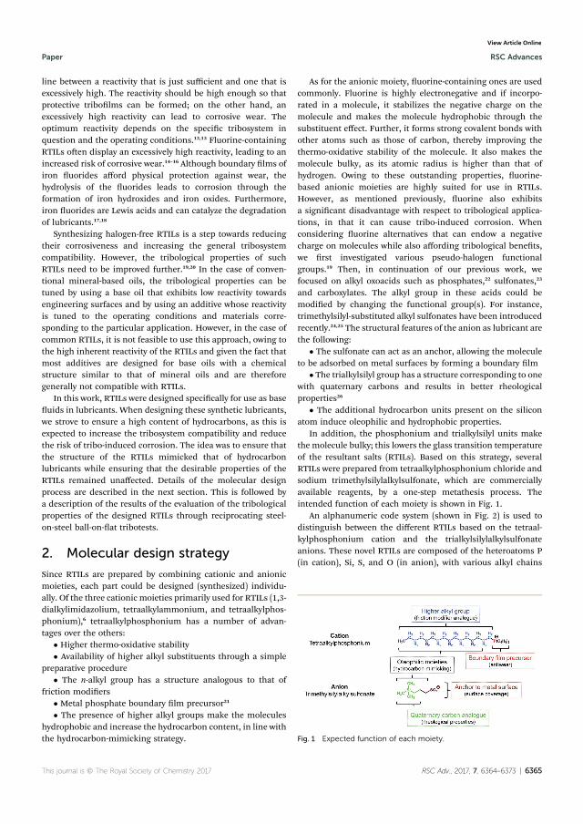
line between a reactivity that is just sufficient and one that isexcessively high. The reactivity should be high enough so thatprotective tribolms can be formed; on the other hand, anexcessively high reactivity can lead to corrosive wear. Theoptimum reactivity depends on the specic tribosystem inquestion and the operating conditions.12,13 Fluorine-containingRTILs oen display an excessively high reactivity, leading to anincreased risk of corrosive wear.14–16 Although boundary lms ofiron uorides afford physical protection against wear, thehydrolysis of the uorides leads to corrosion through theformation of iron hydroxides and iron oxides. Furthermore,iron uorides are Lewis acids and can catalyze the degradationof lubricants.17,18
Synthesizing halogen-free RTILs is a step towards reducingtheir corrosiveness and increasing the general tribosystemcompatibility. However, the tribological properties of suchRTILs need to be improved further.19,20 In the case of conven-tional mineral-based oils, the tribological properties can betuned by using a base oil that exhibits low reactivity towardsengineering surfaces and by using an additive whose reactivityis tuned to the operating conditions and materials corre-sponding to the particular application. However, in the case ofcommon RTILs, it is not feasible to use this approach, owing tothe high inherent reactivity of the RTILs and given the fact thatmost additives are designed for base oils with a chemicalstructure similar to that of mineral oils and are thereforegenerally not compatible with RTILs.
In this work, RTILs were designed specically for use as baseuids in lubricants. When designing these synthetic lubricants,we strove to ensure a high content of hydrocarbons, as this isexpected to increase the tribosystem compatibility and reducethe risk of tribo-induced corrosion. The idea was to ensure thatthe structure of the RTILs mimicked that of hydrocarbonlubricants while ensuring that the desirable properties of theRTILs remained unaffected. Details of the molecular designprocess are described in the next section. This is followed bya description of the results of the evaluation of the tribologicalproperties of the designed RTILs through reciprocating steel-on-steel ball-on-at tribotests.
2. Molecular design strategy
Since RTILs are prepared by combining cationic and anionicmoieties, each part could be designed (synthesized) individu-ally. Of the three cationic moieties primarily used for RTILs (1,3-dialkylimidazolium, tetraalkylammonium, and tetraalkylphos-phonium),6 tetraalkylphosphonium has a number of advan-tages over the others:
� Higher thermo-oxidative stability� Availability of higher alkyl substituents through a simple
preparative procedure� The n-alkyl group has a structure analogous to that of
friction modiers� Metal phosphate boundary lm precursor21
� The presence of higher alkyl groups make the moleculeshydrophobic and increase the hydrocarbon content, in line withthe hydrocarbon-mimicking strategy.
As for the anionic moiety, uorine-containing ones are usedcommonly. Fluorine is highly electronegative and if incorpo-rated in a molecule, it stabilizes the negative charge on themolecule and makes the molecule hydrophobic through thesubstituent effect. Further, it forms strong covalent bonds withother atoms such as those of carbon, thereby improving thethermo-oxidative stability of the molecule. It also makes themolecule bulky, as its atomic radius is higher than that ofhydrogen. Owing to these outstanding properties, uorine-based anionic moieties are highly suited for use in RTILs.However, as mentioned previously, uorine also exhibitsa signicant disadvantage with respect to tribological applica-tions, in that it can cause tribo-induced corrosion. Whenconsidering uorine alternatives that can endow a negativecharge on molecules while also affording tribological benets,we rst investigated various pseudo-halogen functionalgroups.19 Then, in continuation of our previous work, wefocused on alkyl oxoacids such as phosphates,22 sulfonates,23
and carboxylates. The alkyl group in these acids could bemodied by changing the functional group(s). For instance,trimethylsilyl-substituted alkyl sulfonates have been introducedrecently.24,25 The structural features of the anion as lubricant arethe following:
� The sulfonate can act as an anchor, allowing the moleculeto be adsorbed on metal surfaces by forming a boundary lm
� The trialkylsilyl group has a structure corresponding to onewith quaternary carbons and results in better rheologicalproperties26
� The additional hydrocarbon units present on the siliconatom induce oleophilic and hydrophobic properties.
In addition, the phosphonium and trialkylsilyl units makethe molecule bulky; this lowers the glass transition temperatureof the resultant salts (RTILs). Based on this strategy, severalRTILs were prepared from tetraalkylphosphonium chloride andsodium trimethylsilylalkylsulfonate, which are commerciallyavailable reagents, by a one-step metathesis process. Theintended function of each moiety is shown in Fig. 1.
An alphanumeric code system (shown in Fig. 2) is used todistinguish between the different RTILs based on the tetraal-kylphosphonium cation and the trialkylsilylalkylsulfonateanions. These novel RTILs are composed of the heteroatoms P(in cation), Si, S, and O (in anion), with various alkyl chains
Fig. 1 Expected function of each moiety.
This journal is © The Royal Society of Chemistry 2017 RSC Adv., 2017, 7, 6364–6373 | 6365
Paper RSC Advances
Ope
n A
cces
s Arti
cle.
Pub
lishe
d on
19
Janu
ary
2017
. Dow
nloa
ded
on 0
9/02
/201
7 10
:32:
58.
Thi
s arti
cle
is li
cens
ed u
nder
a C
reat
ive
Com
mon
s Attr
ibut
ion
3.0
Unp
orte
d Li
cenc
e.
View Article Online
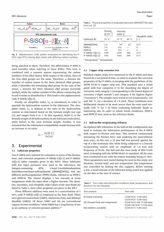
being attached to them. Therefore, the abbreviation P–SiSO isused hereaer when referring to these RTILs. This term iscombined with a numeric system representing the carbonnumbers of the alkyl chains. With respect to the cation, three ofthe four alkyl groups are the same. Therefore, a denotes thenumber of carbon atoms in the three identical alkyl groups,while b identies the remaining alkyl group. In the case of theanion, c denotes the three identical alkyl groups (normallymethyl), while the carbon number of the alkene connecting theSi and S atoms is identied by d. This leads to the alphanumericcode P–SiSO[a-b][c-d].
Finally, an oleophilic index, IO, is introduced, in order toquantify the hydrocarbon content in the lubricants. The oleo-philic index, IO, is dened as the ratio of the hydrocarboncontent as determined based on the formula weight (see eqn(1)) and ranges from 0 to 1. In this equation, fw(H–C) is theformula weight of all hydrocarbons in the lubricant molecule(s),while fw(tot) is the total formula weight. Further, it wasassumed that the tribosystem compatibility would increase withan increase in its value.
IO ¼ fwðH�CÞfwðtotÞ (1)
3. Experimental3.1 Lubricant properties
Two P–SiSOs were selected for evaluation in terms of the friction,wear, and corrosion properties: P–SiSO[4-12][1-2] and P–SiSO[4-16][1-2] (other examples given in the ESI†). Three lubricantswith low vapor pressures were used as the references: thehalogen-containing RTIL 1-butyl-3-methylimidazoliumbis(triuoromethane-sulfonyl)amide ([BMIM][TFSA]), and twodifferent peruoropolyether (PFPE) uids, referred to as PFPE-Land PFPE-H. The former displays a low viscosity at roomtemperature while the latter show a higher viscosity. The densi-ties, viscosities, and oleophilic index values of the neat uids arelisted in Table 1; their other properties are given in the ESI.†
Three different additives were used in a concentration of 5wt%, with P–SiSO[4-16][1-2] employed as the base uid. Therewere glycerol monooleate (GMO), oleylamine (OA), and dibenzyldisulde (DBDS). Of these, GMO and OA are conventionalorganic friction modiers,1 while DBDS has a long history of useas an antiwear or extreme-pressure additive.27
3.2 Copper strip corrosion test
Polished copper strips were immersed in the P–SiSOs and thenheated for a set period of time, in order to evaluate the corrosionproperties of the P–SiSOs, in keeping with the guidelines of theASTM D130-12 copper strip test. This standard uses a visualguide with four categories (1–4) for classifying the degree ofcorrosion, with category 1 corresponding to the lowest degree ofcorrosion (“slight tarnish”) and category 4 the highest degree(“corrosion”). The samples were tested at two temperatures, 150and 200 �C, for a duration of 3 h each. These conditions weredeliberately chosen to be more severe than the ones used nor-mally (100 �C for 3 h) when evaluating hydraulic uids orlubricating oils, in order to mimic harsh conditions. PFPE-Land PFPE-H were used as the reference uids.
3.3 Ball-on-at reciprocating tribotest
An Optimol SRV tribotester in the ball-on-at conguration wasused to evaluate the lubrication performance of the P–SiSOswith respect to friction and wear. This involved continuouslymeasuring the friction force and analyzing the post-tribotestwear scars. In this test, a 10 mm ball was pressed against thetop of a at stationary disc while being subjected to a linearlyreciprocating motion with an amplitude of 1.0 mm andfrequency of 50 Hz. The ball and disc were made of AISI 52100steel, in keeping with the ASTM D6425-11 standard. All the testswere conducted in air, with the relative humidity being 25–50%.Three parameters were varied during the tests in this study: testduration, normal load, and test temperature (the temperaturewas controlled by heating the disc support). Before startinga test, a small amount of the lubricant being tested was appliedon the disc at the area of contact.
Fig. 2 Alphanumeric code system employed for identifying the P–SiSO-type RTILs having alkyl chains with differing carbon numbers.
Table 1 Physical properties of evaluated lubricants ([BMIM][TFSA] datafrom ref. 22)
Lubricant ID
Density[g cm�3]
Viscosity[mPa s]
Oleophilic index[—]25 �C 25 �C 60 �C
[BMIM][TFSA] 1.4 70a 22b 0.27PFPE-L 1.9 113 — 0PFPE-H 1.9 513 — 0P–SiSO[4-12][1-2] 0.90 2570 208 0.75P–SiSO[4-16][1-2] 0.91 1932 269 0.77
a Extrapolated. b Interpolated.
Table 2 Test codes describing the conditions (load, temperature, andduration) for the tribotests
Test scenario Test code
(I) Initial screening C{100 N/25 �C/60 min}C{150 N/25 �C/60 min}
(II) Elevated load and temperature V{100 N/25–100 �C/180 min}V{100–300 N/25 �C/150 min}
(III) Additive suitability C{100 N/75 �C/60 min}
6366 | RSC Adv., 2017, 7, 6364–6373 This journal is © The Royal Society of Chemistry 2017
RSC Advances Paper
Ope
n A
cces
s Arti
cle.
Pub
lishe
d on
19
Janu
ary
2017
. Dow
nloa
ded
on 0
9/02
/201
7 10
:32:
58.
Thi
s arti
cle
is li
cens
ed u
nder
a C
reat
ive
Com
mon
s Attr
ibut
ion
3.0
Unp
orte
d Li
cenc
e.
View Article Online
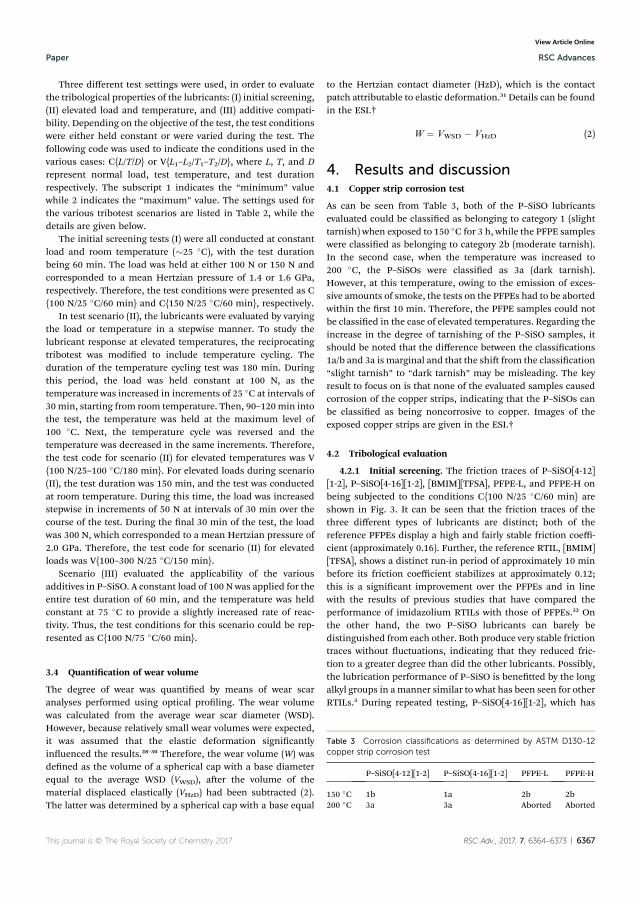
Three different test settings were used, in order to evaluatethe tribological properties of the lubricants: (I) initial screening,(II) elevated load and temperature, and (III) additive compati-bility. Depending on the objective of the test, the test conditionswere either held constant or were varied during the test. Thefollowing code was used to indicate the conditions used in thevarious cases: C{L/T/D} or V{L1–L2/T1–T2/D}, where L, T, and Drepresent normal load, test temperature, and test durationrespectively. The subscript 1 indicates the “minimum” valuewhile 2 indicates the “maximum” value. The settings used forthe various tribotest scenarios are listed in Table 2, while thedetails are given below.
The initial screening tests (I) were all conducted at constantload and room temperature (�25 �C), with the test durationbeing 60 min. The load was held at either 100 N or 150 N andcorresponded to a mean Hertzian pressure of 1.4 or 1.6 GPa,respectively. Therefore, the test conditions were presented as C{100 N/25 �C/60 min} and C{150 N/25 �C/60 min}, respectively.
In test scenario (II), the lubricants were evaluated by varyingthe load or temperature in a stepwise manner. To study thelubricant response at elevated temperatures, the reciprocatingtribotest was modied to include temperature cycling. Theduration of the temperature cycling test was 180 min. Duringthis period, the load was held constant at 100 N, as thetemperature was increased in increments of 25 �C at intervals of30 min, starting from room temperature. Then, 90–120min intothe test, the temperature was held at the maximum level of100 �C. Next, the temperature cycle was reversed and thetemperature was decreased in the same increments. Therefore,the test code for scenario (II) for elevated temperatures was V{100 N/25–100 �C/180 min}. For elevated loads during scenario(II), the test duration was 150 min, and the test was conductedat room temperature. During this time, the load was increasedstepwise in increments of 50 N at intervals of 30 min over thecourse of the test. During the nal 30 min of the test, the loadwas 300 N, which corresponded to a mean Hertzian pressure of2.0 GPa. Therefore, the test code for scenario (II) for elevatedloads was V{100–300 N/25 �C/150 min}.
Scenario (III) evaluated the applicability of the variousadditives in P–SiSO. A constant load of 100 N was applied for theentire test duration of 60 min, and the temperature was heldconstant at 75 �C to provide a slightly increased rate of reac-tivity. Thus, the test conditions for this scenario could be rep-resented as C{100 N/75 �C/60 min}.
3.4 Quantication of wear volume
The degree of wear was quantied by means of wear scaranalyses performed using optical proling. The wear volumewas calculated from the average wear scar diameter (WSD).However, because relatively small wear volumes were expected,it was assumed that the elastic deformation signicantlyinuenced the results.28–30 Therefore, the wear volume (W) wasdened as the volume of a spherical cap with a base diameterequal to the average WSD (VWSD), aer the volume of thematerial displaced elastically (VHzD) had been subtracted (2).The latter was determined by a spherical cap with a base equal
to the Hertzian contact diameter (HzD), which is the contactpatch attributable to elastic deformation.31 Details can be foundin the ESI.†
W ¼ VWSD � VHzD (2)
4. Results and discussion4.1 Copper strip corrosion test
As can be seen from Table 3, both of the P–SiSO lubricantsevaluated could be classied as belonging to category 1 (slighttarnish) when exposed to 150 �C for 3 h, while the PFPE sampleswere classied as belonging to category 2b (moderate tarnish).In the second case, when the temperature was increased to200 �C, the P–SiSOs were classied as 3a (dark tarnish).However, at this temperature, owing to the emission of exces-sive amounts of smoke, the tests on the PFPEs had to be abortedwithin the rst 10 min. Therefore, the PFPE samples could notbe classied in the case of elevated temperatures. Regarding theincrease in the degree of tarnishing of the P–SiSO samples, itshould be noted that the difference between the classications1a/b and 3a is marginal and that the shi from the classication“slight tarnish” to “dark tarnish” may be misleading. The keyresult to focus on is that none of the evaluated samples causedcorrosion of the copper strips, indicating that the P–SiSOs canbe classied as being noncorrosive to copper. Images of theexposed copper strips are given in the ESI.†
4.2 Tribological evaluation
4.2.1 Initial screening. The friction traces of P–SiSO[4-12][1-2], P–SiSO[4-16][1-2], [BMIM][TFSA], PFPE-L, and PFPE-H onbeing subjected to the conditions C{100 N/25 �C/60 min} areshown in Fig. 3. It can be seen that the friction traces of thethree different types of lubricants are distinct; both of thereference PFPEs display a high and fairly stable friction coeffi-cient (approximately 0.16). Further, the reference RTIL, [BMIM][TFSA], shows a distinct run-in period of approximately 10 minbefore its friction coefficient stabilizes at approximately 0.12;this is a signicant improvement over the PFPEs and in linewith the results of previous studies that have compared theperformance of imidazolium RTILs with those of PFPEs.32 Onthe other hand, the two P–SiSO lubricants can barely bedistinguished from each other. Both produce very stable frictiontraces without uctuations, indicating that they reduced fric-tion to a greater degree than did the other lubricants. Possibly,the lubrication performance of P–SiSO is benetted by the longalkyl groups in amanner similar to what has been seen for otherRTILs.3 During repeated testing, P–SiSO[4-16][1-2], which has
Table 3 Corrosion classifications as determined by ASTM D130-12copper strip corrosion test
P–SiSO[4-12][1-2] P–SiSO[4-16][1-2] PFPE-L PFPE-H
150 �C 1b 1a 2b 2b200 �C 3a 3a Aborted Aborted
This journal is © The Royal Society of Chemistry 2017 RSC Adv., 2017, 7, 6364–6373 | 6367
Paper RSC Advances
Ope
n A
cces
s Arti
cle.
Pub
lishe
d on
19
Janu
ary
2017
. Dow
nloa
ded
on 0
9/02
/201
7 10
:32:
58.
Thi
s arti
cle
is li
cens
ed u
nder
a C
reat
ive
Com
mon
s Attr
ibut
ion
3.0
Unp
orte
d Li
cenc
e.
View Article Online
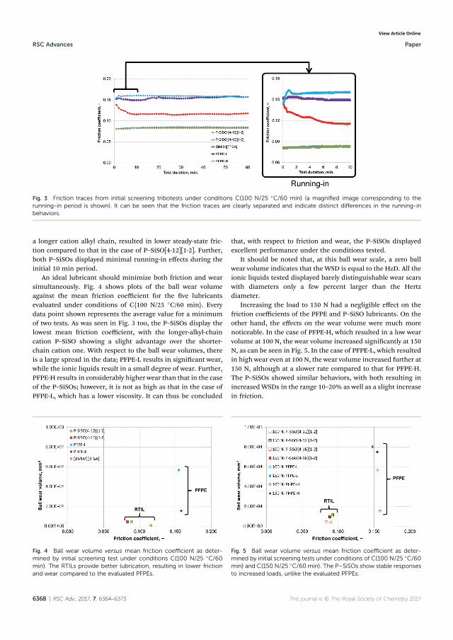
a longer cation alkyl chain, resulted in lower steady-state fric-tion compared to that in the case of P–SiSO[4-12][1-2]. Further,both P–SiSOs displayed minimal running-in effects during theinitial 10 min period.
An ideal lubricant should minimize both friction and wearsimultaneously. Fig. 4 shows plots of the ball wear volumeagainst the mean friction coefficient for the ve lubricantsevaluated under conditions of C{100 N/25 �C/60 min}. Everydata point shown represents the average value for a minimumof two tests. As was seen in Fig. 3 too, the P–SiSOs display thelowest mean friction coefficient, with the longer-alkyl-chaincation P–SiSO showing a slight advantage over the shorter-chain cation one. With respect to the ball wear volumes, thereis a large spread in the data; PFPE-L results in signicant wear,while the ionic liquids result in a small degree of wear. Further,PFPE-H results in considerably higher wear than that in the caseof the P–SiSOs; however, it is not as high as that in the case ofPFPE-L, which has a lower viscosity. It can thus be concluded
that, with respect to friction and wear, the P–SiSOs displayedexcellent performance under the conditions tested.
It should be noted that, at this ball wear scale, a zero ballwear volume indicates that the WSD is equal to the HzD. All theionic liquids tested displayed barely distinguishable wear scarswith diameters only a few percent larger than the Hertzdiameter.
Increasing the load to 150 N had a negligible effect on thefriction coefficients of the PFPE and P–SiSO lubricants. On theother hand, the effects on the wear volume were much morenoticeable. In the case of PFPE-H, which resulted in a low wearvolume at 100 N, the wear volume increased signicantly at 150N, as can be seen in Fig. 5. In the case of PFPE-L, which resultedin high wear even at 100 N, the wear volume increased further at150 N, although at a slower rate compared to that for PFPE-H.The P–SiSOs showed similar behaviors, with both resulting inincreased WSDs in the range 10–20% as well as a slight increasein friction.
Fig. 3 Friction traces from initial screening tribotests under conditions C{100 N/25 �C/60 min} (a magnified image corresponding to therunning-in period is shown). It can be seen that the friction traces are clearly separated and indicate distinct differences in the running-inbehaviors.
Fig. 4 Ball wear volume versus mean friction coefficient as deter-mined by initial screening test under conditions C{100 N/25 �C/60min}. The RTILs provide better lubrication, resulting in lower frictionand wear compared to the evaluated PFPEs.
Fig. 5 Ball wear volume versus mean friction coefficient as deter-mined by initial screening tests under conditions of C{100 N/25 �C/60min} and C{150 N/25 �C/60 min}. The P–SiSOs show stable responsesto increased loads, unlike the evaluated PFPEs.
6368 | RSC Adv., 2017, 7, 6364–6373 This journal is © The Royal Society of Chemistry 2017
RSC Advances Paper
Ope
n A
cces
s Arti
cle.
Pub
lishe
d on
19
Janu
ary
2017
. Dow
nloa
ded
on 0
9/02
/201
7 10
:32:
58.
Thi
s arti
cle
is li
cens
ed u
nder
a C
reat
ive
Com
mon
s Attr
ibut
ion
3.0
Unp
orte
d Li
cenc
e.
View Article Online
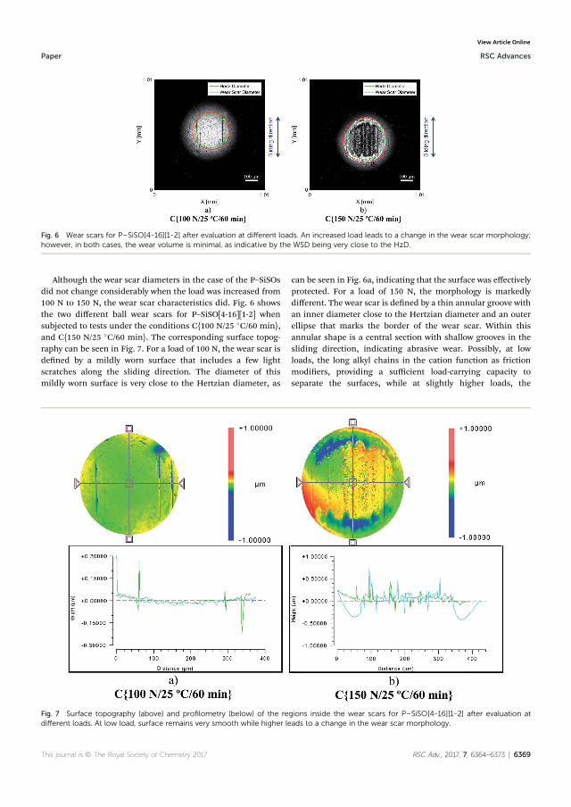
Although the wear scar diameters in the case of the P–SiSOsdid not change considerably when the load was increased from100 N to 150 N, the wear scar characteristics did. Fig. 6 showsthe two different ball wear scars for P–SiSO[4-16][1-2] whensubjected to tests under the conditions C{100 N/25 �C/60 min},and C{150 N/25 �C/60 min}. The corresponding surface topog-raphy can be seen in Fig. 7. For a load of 100 N, the wear scar isdened by a mildly worn surface that includes a few lightscratches along the sliding direction. The diameter of thismildly worn surface is very close to the Hertzian diameter, as
can be seen in Fig. 6a, indicating that the surface was effectivelyprotected. For a load of 150 N, the morphology is markedlydifferent. The wear scar is dened by a thin annular groove withan inner diameter close to the Hertzian diameter and an outerellipse that marks the border of the wear scar. Within thisannular shape is a central section with shallow grooves in thesliding direction, indicating abrasive wear. Possibly, at lowloads, the long alkyl chains in the cation function as frictionmodiers, providing a sufficient load-carrying capacity toseparate the surfaces, while at slightly higher loads, the
Fig. 7 Surface topography (above) and profilometry (below) of the regions inside the wear scars for P–SiSO[4-16][1-2] after evaluation atdifferent loads. At low load, surface remains very smooth while higher leads to a change in the wear scar morphology.
Fig. 6 Wear scars for P–SiSO[4-16][1-2] after evaluation at different loads. An increased load leads to a change in the wear scar morphology;however, in both cases, the wear volume is minimal, as indicative by the WSD being very close to the HzD.
This journal is © The Royal Society of Chemistry 2017 RSC Adv., 2017, 7, 6364–6373 | 6369
Paper RSC Advances
Ope
n A
cces
s Arti
cle.
Pub
lishe
d on
19
Janu
ary
2017
. Dow
nloa
ded
on 0
9/02
/201
7 10
:32:
58.
Thi
s arti
cle
is li
cens
ed u
nder
a C
reat
ive
Com
mon
s Attr
ibut
ion
3.0
Unp
orte
d Li
cenc
e.
View Article Online
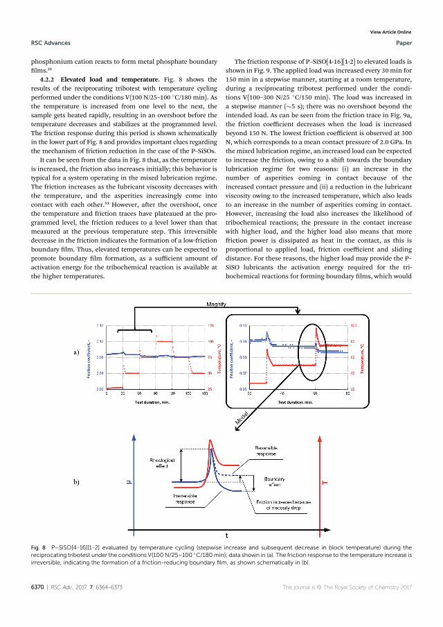
phosphonium cation reacts to form metal phosphate boundarylms.21
4.2.2 Elevated load and temperature. Fig. 8 shows theresults of the reciprocating tribotest with temperature cyclingperformed under the conditions V{100 N/25–100 �C/180 min}. Asthe temperature is increased from one level to the next, thesample gets heated rapidly, resulting in an overshoot before thetemperature decreases and stabilizes at the programmed level.The friction response during this period is shown schematicallyin the lower part of Fig. 8 and provides important clues regardingthe mechanism of friction reduction in the case of the P–SiSOs.
It can be seen from the data in Fig. 8 that, as the temperatureis increased, the friction also increases initially; this behavior istypical for a system operating in the mixed lubrication regime.The friction increases as the lubricant viscosity decreases withthe temperature, and the asperities increasingly come intocontact with each other.33 However, aer the overshoot, oncethe temperature and friction traces have plateaued at the pro-grammed level, the friction reduces to a level lower than thatmeasured at the previous temperature step. This irreversibledecrease in the friction indicates the formation of a low-frictionboundary lm. Thus, elevated temperatures can be expected topromote boundary lm formation, as a sufficient amount ofactivation energy for the tribochemical reaction is available atthe higher temperatures.
The friction response of P–SiSO[4-16][1-2] to elevated loads isshown in Fig. 9. The applied load was increased every 30 min for150 min in a stepwise manner, starting at a room temperature,during a reciprocating tribotest performed under the condi-tions V{100–300 N/25 �C/150 min}. The load was increased ina stepwise manner (�5 s); there was no overshoot beyond theintended load. As can be seen from the friction trace in Fig. 9a,the friction coefficient decreases when the load is increasedbeyond 150 N. The lowest friction coefficient is observed at 300N, which corresponds to a mean contact pressure of 2.0 GPa. Inthemixed lubrication regime, an increased load can be expectedto increase the friction, owing to a shi towards the boundarylubrication regime for two reasons: (i) an increase in thenumber of asperities coming in contact because of theincreased contact pressure and (ii) a reduction in the lubricantviscosity owing to the increased temperature, which also leadsto an increase in the number of asperities coming in contact.However, increasing the load also increases the likelihood oftribochemical reactions; the pressure in the contact increasewith higher load, and the higher load also means that morefriction power is dissipated as heat in the contact, as this isproportional to applied load, friction coefficient and slidingdistance. For these reasons, the higher load may provide the P–SiSO lubricants the activation energy required for the tri-bochemical reactions for forming boundary lms, which would
Fig. 8 P–SiSO[4-16][1-2] evaluated by temperature cycling (stepwise increase and subsequent decrease in block temperature) during thereciprocating tribotest under the conditions V{100N/25–100 �C/180min}; data shown in (a). The friction response to the temperature increase isirreversible, indicating the formation of a friction-reducing boundary film, as shown schematically in (b).
6370 | RSC Adv., 2017, 7, 6364–6373 This journal is © The Royal Society of Chemistry 2017
RSC Advances Paper
Ope
n A
cces
s Arti
cle.
Pub
lishe
d on
19
Janu
ary
2017
. Dow
nloa
ded
on 0
9/02
/201
7 10
:32:
58.
Thi
s arti
cle
is li
cens
ed u
nder
a C
reat
ive
Com
mon
s Attr
ibut
ion
3.0
Unp
orte
d Li
cenc
e.
View Article Online
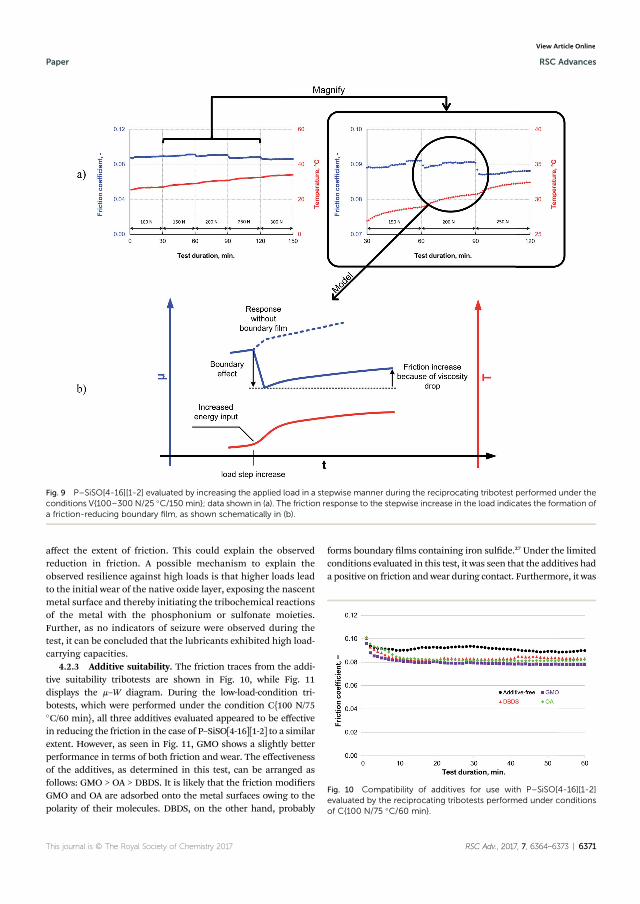
affect the extent of friction. This could explain the observedreduction in friction. A possible mechanism to explain theobserved resilience against high loads is that higher loads leadto the initial wear of the native oxide layer, exposing the nascentmetal surface and thereby initiating the tribochemical reactionsof the metal with the phosphonium or sulfonate moieties.Further, as no indicators of seizure were observed during thetest, it can be concluded that the lubricants exhibited high load-carrying capacities.
4.2.3 Additive suitability. The friction traces from the addi-tive suitability tribotests are shown in Fig. 10, while Fig. 11displays the m–W diagram. During the low-load-condition tri-botests, which were performed under the condition C{100 N/75�C/60 min}, all three additives evaluated appeared to be effectivein reducing the friction in the case of P–SiSO[4-16][1-2] to a similarextent. However, as seen in Fig. 11, GMO shows a slightly betterperformance in terms of both friction and wear. The effectivenessof the additives, as determined in this test, can be arranged asfollows: GMO > OA > DBDS. It is likely that the friction modiersGMO and OA are adsorbed onto the metal surfaces owing to thepolarity of their molecules. DBDS, on the other hand, probably
forms boundary lms containing iron sulde.27 Under the limitedconditions evaluated in this test, it was seen that the additives hada positive on friction andwear during contact. Furthermore, it was
Fig. 10 Compatibility of additives for use with P–SiSO[4-16][1-2]evaluated by the reciprocating tribotests performed under conditionsof C{100 N/75 �C/60 min}.
Fig. 9 P–SiSO[4-16][1-2] evaluated by increasing the applied load in a stepwise manner during the reciprocating tribotest performed under theconditions V{100–300 N/25 �C/150 min}; data shown in (a). The friction response to the stepwise increase in the load indicates the formation ofa friction-reducing boundary film, as shown schematically in (b).
This journal is © The Royal Society of Chemistry 2017 RSC Adv., 2017, 7, 6364–6373 | 6371
Paper RSC Advances
Ope
n A
cces
s Arti
cle.
Pub
lishe
d on
19
Janu
ary
2017
. Dow
nloa
ded
on 0
9/02
/201
7 10
:32:
58.
Thi
s arti
cle
is li
cens
ed u
nder
a C
reat
ive
Com
mon
s Attr
ibut
ion
3.0
Unp
orte
d Li
cenc
e.
View Article Online
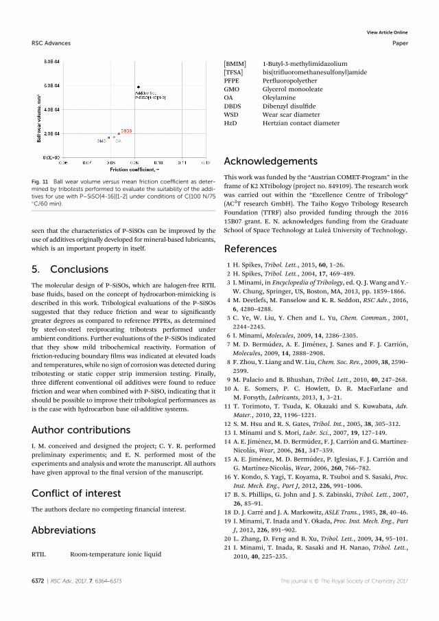
seen that the characteristics of P–SiSOs can be improved by theuse of additives originally developed formineral-based lubricants,which is an important property in itself.
5. Conclusions
The molecular design of P–SiSOs, which are halogen-free RTILbase uids, based on the concept of hydrocarbon-mimicking isdescribed in this work. Tribological evaluations of the P–SiSOssuggested that they reduce friction and wear to signicantlygreater degrees as compared to reference PFPEs, as determinedby steel-on-steel reciprocating tribotests performed underambient conditions. Further evaluations of the P–SiSOs indicatedthat they show mild tribochemical reactivity. Formation offriction-reducing boundary lms was indicated at elevated loadsand temperatures, while no sign of corrosion was detected duringtribotesting or static copper strip immersion testing. Finally,three different conventional oil additives were found to reducefriction and wear when combined with P–SiSO, indicating that itshould be possible to improve their tribological performances asis the case with hydrocarbon base oil-additive systems.
Author contributions
I. M. conceived and designed the project; C. Y. R. performedpreliminary experiments; and E. N. performed most of theexperiments and analysis and wrote the manuscript. All authorshave given approval to the nal version of the manuscript.
Conflict of interest
The authors declare no competing nancial interest.
Abbreviations
RTIL Room-temperature ionic liquid
[BMIM][TFSA]
1-Butyl-3-methylimidazoliumbis(triuoromethanesulfonyl)amide
PFPE PeruoropolyetherGMO Glycerol monooleateOA OleylamineDBDS Dibenzyl disuldeWSD Wear scar diameterHzD Hertzian contact diameter
Acknowledgements
This work was funded by the “Austrian COMET-Program” in theframe of K2 XTribology (project no. 849109). The research workwas carried out within the “Excellence Centre of Tribology”(AC2T research GmbH). The Taiho Kogyo Tribology ResearchFoundation (TTRF) also provided funding through the 201615B07 grant. E. N. acknowledges funding from the GraduateSchool of Space Technology at Lulea University of Technology.
References
1 H. Spikes, Tribol. Lett., 2015, 60, 1–26.2 H. Spikes, Tribol. Lett., 2004, 17, 469–489.3 I. Minami, in Encyclopedia of Tribology, ed. Q. J. Wang and Y.-W. Chung, Springer, US, Boston, MA, 2013, pp. 1859–1866.
4 M. Deetlefs, M. Fanselow and K. R. Seddon, RSC Adv., 2016,6, 4280–4288.
5 C. Ye, W. Liu, Y. Chen and L. Yu, Chem. Commun., 2001,2244–2245.
6 I. Minami, Molecules, 2009, 14, 2286–2305.7 M. D. Bermudez, A. E. Jimenez, J. Sanes and F. J. Carrion,Molecules, 2009, 14, 2888–2908.
8 F. Zhou, Y. Liang andW. Liu, Chem. Soc. Rev., 2009, 38, 2590–2599.
9 M. Palacio and B. Bhushan, Tribol. Lett., 2010, 40, 247–268.10 A. E. Somers, P. C. Howlett, D. R. MacFarlane and
M. Forsyth, Lubricants, 2013, 1, 3–21.11 T. Torimoto, T. Tsuda, K. Okazaki and S. Kuwabata, Adv.
Mater., 2010, 22, 1196–1221.12 S. M. Hsu and R. S. Gates, Tribol. Int., 2005, 38, 305–312.13 I. Minami and S. Mori, Lubr. Sci., 2007, 19, 127–149.14 A. E. Jimenez, M. D. Bermudez, F. J. Carrion and G. Martınez-
Nicolas, Wear, 2006, 261, 347–359.15 A. E. Jimenez, M. D. Bermudez, P. Iglesias, F. J. Carrion and
G. Martınez-Nicolas, Wear, 2006, 260, 766–782.16 Y. Kondo, S. Yagi, T. Koyama, R. Tsuboi and S. Sasaki, Proc.
Inst. Mech. Eng., Part J, 2012, 226, 991–1006.17 B. S. Phillips, G. John and J. S. Zabinski, Tribol. Lett., 2007,
26, 85–91.18 D. J. Carre and J. A. Markowitz, ASLE Trans., 1985, 28, 40–46.19 I. Minami, T. Inada and Y. Okada, Proc. Inst. Mech. Eng., Part
J, 2012, 226, 891–902.20 L. Zhang, D. Feng and B. Xu, Tribol. Lett., 2009, 34, 95–101.21 I. Minami, T. Inada, R. Sasaki and H. Nanao, Tribol. Lett.,
2010, 40, 225–235.
Fig. 11 Ball wear volume versus mean friction coefficient as deter-mined by tribotests performed to evaluate the suitability of the addi-tives for use with P–SiSO[4-16][1-2] under conditions of C{100 N/75�C/60 min}.
6372 | RSC Adv., 2017, 7, 6364–6373 This journal is © The Royal Society of Chemistry 2017
RSC Advances Paper
Ope
n A
cces
s Arti
cle.
Pub
lishe
d on
19
Janu
ary
2017
. Dow
nloa
ded
on 0
9/02
/201
7 10
:32:
58.
Thi
s arti
cle
is li
cens
ed u
nder
a C
reat
ive
Com
mon
s Attr
ibut
ion
3.0
Unp
orte
d Li
cenc
e.
View Article Online
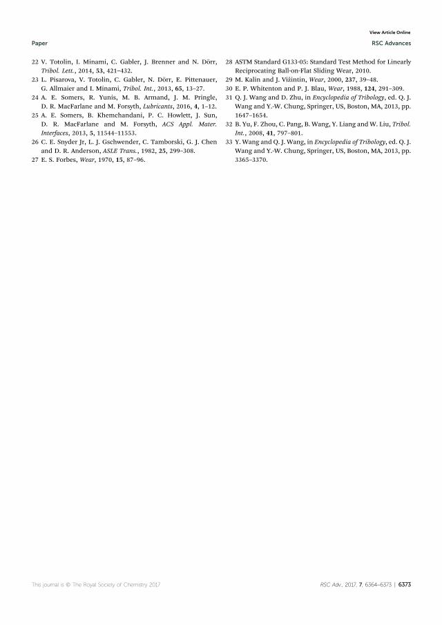
22 V. Totolin, I. Minami, C. Gabler, J. Brenner and N. Dorr,Tribol. Lett., 2014, 53, 421–432.
23 L. Pisarova, V. Totolin, C. Gabler, N. Dorr, E. Pittenauer,G. Allmaier and I. Minami, Tribol. Int., 2013, 65, 13–27.
24 A. E. Somers, R. Yunis, M. B. Armand, J. M. Pringle,D. R. MacFarlane and M. Forsyth, Lubricants, 2016, 4, 1–12.
25 A. E. Somers, B. Khemchandani, P. C. Howlett, J. Sun,D. R. MacFarlane and M. Forsyth, ACS Appl. Mater.Interfaces, 2013, 5, 11544–11553.
26 C. E. Snyder Jr, L. J. Gschwender, C. Tamborski, G. J. Chenand D. R. Anderson, ASLE Trans., 1982, 25, 299–308.
27 E. S. Forbes, Wear, 1970, 15, 87–96.
28 ASTM Standard G133-05: Standard Test Method for LinearlyReciprocating Ball-on-Flat Sliding Wear, 2010.
29 M. Kalin and J. Vizintin, Wear, 2000, 237, 39–48.30 E. P. Whitenton and P. J. Blau, Wear, 1988, 124, 291–309.31 Q. J. Wang and D. Zhu, in Encyclopedia of Tribology, ed. Q. J.
Wang and Y.-W. Chung, Springer, US, Boston, MA, 2013, pp.1647–1654.
32 B. Yu, F. Zhou, C. Pang, B. Wang, Y. Liang andW. Liu, Tribol.Int., 2008, 41, 797–801.
33 Y. Wang and Q. J. Wang, in Encyclopedia of Tribology, ed. Q. J.Wang and Y.-W. Chung, Springer, US, Boston, MA, 2013, pp.3365–3370.
This journal is © The Royal Society of Chemistry 2017 RSC Adv., 2017, 7, 6364–6373 | 6373
Paper RSC Advances
Ope
n A
cces
s Arti
cle.
Pub
lishe
d on
19
Janu
ary
2017
. Dow
nloa
ded
on 0
9/02
/201
7 10
:32:
58.
Thi
s arti
cle
is li
cens
ed u
nder
a C
reat
ive
Com
mon
s Attr
ibut
ion
3.0
Unp
orte
d Li
cenc
e.
View Article Online
56
PAPER II
FORMATION OF BOUNDARY FILM FROM IONIC LIQUIDS
ENHANCED BY ADDITIVES
Authors: E. Nyberg, J. Mouzon, M. Grahn, and I. Minami
Journal: Applied Sciences, vol. 7, no. 5, p. 433, 2017.
This article is the featured paper in the Special Issue Lubricant Additives
Content: This article reports the tribological evaluation supported by
surface analysis of conventional additives in a novel hydrocarbon-
mimicking ionic liquid (P-SiSO). The boundary film formation of these
novel fluids is analyzed. The results reveal the formation of an effective
boundary film composed of mainly Si and O, that could be further
enhanced by an amine additive.
Author contribution: E.N. performed most of the experiments and
analysis, and wrote the manuscript.
Published by MDPI AG, Basel, Switzerland.

applied sciences
Article
Formation of Boundary Film from Ionic LiquidsEnhanced by Additives
Erik Nyberg 1,*, Johanne Mouzon 2, Mattias Grahn 2 and Ichiro Minami 1
1 Division of Machine Elements, Department of Engineering Sciences and Mathematics,Luleå University of Technology, Luleå SE-97187, Sweden; [email protected]
2 Chemical Technology, Luleå University of Technology, Luleå SE-97187, Sweden;[email protected] (J.M.); [email protected] (M.G.)
* Correspondence: [email protected]; Tel.: +46-920-491-237
Academic Editor: Jun KubotaReceived: 5 March 2017; Accepted: 20 April 2017; Published: 26 April 2017
Abstract: Room temperature ionic liquids (RTILs) have several properties that make them interestingcandidates as base fluids for extreme conditions. However, a lack of compatibility with tribo-improvingadditives combined with an often overly aggressive nature is limiting their use as base fluids.To overcome these drawbacks, hydrocarbon-imitating RTIL base fluids have recently been developed.In this study, the effects of several common additives in the novel RTIL (P-SiSO) were examined bylaboratory tribotesting. A reciprocating steel-steel ball-on-flat setup in an air atmosphere was used,where the lubricant performance was evaluated over a range of loads and temperatures. Surfaceanalyses after testing were carried out using optical profilometry, scanning electron microscopy (SEM),and energy dispersive X-ray spectroscopy (EDS). Neat P-SiSO displayed high performance in thetribotests. At an elevated load and temperature, a shift in lubrication mode was observed with anaccompanying increase in friction and wear. Surface analysis revealed a boundary film rich in Si and Oin the primary lubrication mode, while P was detected after a shift to the secondary lubrication mode.An amine additive was effective in reducing wear and friction under harsh conditions. The aminewas determined to increase formation of the protective Si–O film, presumably by enhancing theanion activity.
Keywords: boundary lubrication; friction modification; wear prevention; RTIL; synthetic lubricant;surface morphology; surface chemistry; trimethylsilyl; alkylsulfonate; tribology
1. Introduction
Lubricants enable the efficient and reliable operation of moving mechanical assemblies by reducingfriction and wear. Ideally, a lubricant film fully separates the moving surfaces so that wear is minimizedand friction is limited to shearing of the viscous film. Unfortunately, there are many cases where the fluidfilm cannot be maintained and the asperities of the surfaces come into direct contact (i.e., the systemoperates in the mixed or boundary lubrication regime). To avoid excessive wear in these regimes, wearand friction reducing additives are required.
The past century has seen the development of an extensive set of lubricant additives that cansignificantly improve the tribological performance of hydrocarbon oils in combination with steelsurfaces [1,2]. Predicting additive effectiveness; however, is very complex. The additive performanceis well known to be dependent on the entire tribosystem, meaning that the effect of base fluids, surfacematerials, and operating conditions all must be considered [3]. Our understanding of tribo-improvingadditives is still evolving, and significant clues on the mechanisms of these are still being uncovered [4,5].
Boundary lubrication (BL) additives are generally categorized as extreme pressure (EP) oranti-wear (AW) additives and form boundary films by adsorption on metal surfaces followed by
Appl. Sci. 2017, 7, 433; doi:10.3390/app7050433 www.mdpi.com/journal/applsci
Appl. Sci. 2017, 7, 433 2 of 14
chemical reaction [6]. AW films form a protective film that shields the underlying surface, whereassacrificial EP films can actually increase wear, but are used to prevent catastrophic seizure [3].The mechanism of film formation implies that two rates must be controlled: first, the rate of adsorptiononto the surface; and second, the rate of formation of the reacted films, which must be balancedin accordance to the operational conditions faced [7]. To correctly balance both rates in practicalapplications is a challenging task that is further complicated by interference between different additives,as well as the influence of the base fluid quality. Therefore, arriving at successful lubricant formulations(base oil and additive combination) has been largely empirical in nature.
Synthetic base fluids are increasingly being relied upon to meet requirements of low volatilityand thermal stability; however, the additive technology developed for hydrocarbon base fluids is notnecessarily applicable due to the significant difference in chemical structure between the traditionalhydrocarbon base fluids and the novel advanced synthetic fluids. In many cases, the conventionaladditives are not miscible [8,9]. In other cases, if the base fluid is very polar, miscibility may becomeexcessive, resulting in a low affinity for the metal surfaces it should protect [10].
Room temperature ionic liquids (RTILs) are a class of advanced synthetic fluids that are highlypolar as the fluids consist entirely of cations and anions [11–14]. These fluids were first suggestedas advanced lubricating fluids in 2001 in Reference [15]. As described in Reference [16], they havebeen intensely researched in many fields, including tribology, over the past two decades. The ionicnature means that RTILs readily adsorb on metal surfaces and under tribological conditions canform boundary films, even as neat fluids [17,18]. However, as mentioned above, optimum reactivitydepends on the entire tribosystem, and even though RTIL properties can be tailored by modifyingtheir chemical structure, this is inefficient compared to the approach of base fluid–additive systems.Additives provide the option to fine tune lubricant performance to meet the demands of specificoperational conditions without redesigning the base fluid. There have been many attempts withboth conventional and unconventional additives for RTILs [19–23], but inherently high reactivityremains problematic. However, in our recent work, hydrocarbon-mimicking ionic liquids have beendesigned for use as base fluids to reduce the inherent reactivity and enable compatibility with existingadditives [24].
In this work, additive technology for RTILs was investigated by use of a hydrocarbon-mimickingionic liquid in a reciprocating steel–steel ball-on-flat tribotest. In our previous work [24], it wasfound that neat RTIL lubricants—designated as P-SiSO—showed low friction and wear in this typeof tribotest, at 25 ◦C and maximum Hertz pressure up to 2.4 GPa. Friction performance was seen toremain low and steady for elevated loads up to 3.0 GPa at 25 ◦C, and common lubricant additiveswere seen to influence friction; however, no surface analysis was performed at elevated loads or forthe additivated samples, so the effect on wear was not determined. Therefore, in this study, surfaceanalysis post-testing were carried out by optical profilometry, scanning electron microscopy (SEM),and energy dispersive X-ray spectroscopy (EDS). The first objective was to determine the limits of theoperational envelope, i.e., at what conditions in this tribotest does the tribological performance of neatP-SiSO deteriorate so that low friction and wear can no longer be maintained. The second objectivewas to investigate the effect of additives on extending the operational envelope of P-SiSO.
2. Materials and Methods
2.1. Lubricant Properties
A hydrocarbon-mimicking RTIL with the chemical formula [(n-C6H13)3(n-C14H29)P]·[(CH3)3SiC2H4SO3]—designated as P-SiSO—was used as the base fluid in these experiments. P-SiSOwas synthesized by Nisshinbo Holdings Inc. (Tokyo, Japan), and the molecular design of P-SiSO hasbeen described in Reference [24]. A low vapor pressure fluid (Fomblin Y 317950)—designated asPFPE—was supplied by Sigma-Aldrich (Stockholm, Sweden) and used as the reference lubricant.
Appl. Sci. 2017, 7, 433 3 of 14
The linear formula of PFPE is CF3O[–CF(CF3)CF2O–]x(–CF2O–)yCF3, and its molecular weightis 3300 g/mol.
Five different additives were used, and are referred to as OA, PNA, DMOP, BHT, and OPP,and their respective detailed description is provided below. Oleylamine (OA) (80–90% C-18, primaryamines >98%), was supplied by Fisher Scientific (Göteborg, Sweden); and N-Phenyl-1-naphthylamine(PNA) (reagent grade, 98%), 5,5-dimethyl-1,3,2-dioxaphosphorinan-2-one (DMOP) (96%), and2,6-di-tert-butyl-4-methylphenol (BHT) (>99%) were supplied by Sigma-Aldrich (Stockholm, Sweden).Ortho-phenylene phosphate (OPP) was prepared as described in Reference [25]. These five additiveswere used to prepare seven lubricant samples with P-SiSO as the base fluid: five single additive samples,and two samples where OPP was combined with either of the amines (OA, PNA), as synergistic effectsbetween OPP and OA have previously been reported in Reference [25]. In all samples, the additiveswere added at a concentration of 10 mmol/kg. The chemical structures of the ionic liquid base fluidand the five additives are depicted in Figure 1. Density and viscosity properties can be found in theSupplementary Information (SI).
Appl. Sci. 2017, 7, 433 3 of 14
(reagent grade, 98%), 5,5-dimethyl-1,3,2-dioxaphosphorinan-2-one (DMOP) (96%), and 2,6-di-tert-butyl-4-methylphenol (BHT) (>99%) were supplied by Sigma-Aldrich (Stockholm, Sweden). Ortho-phenylene phosphate (OPP) was prepared as described in Reference [25]. These five additives were used to prepare seven lubricant samples with P-SiSO as the base fluid: five single additive samples, and two samples where OPP was combined with either of the amines (OA, PNA), as synergistic effects between OPP and OA have previously been reported in Reference [25]. In all samples, the additives were added at a concentration of 10 mmol/kg. The chemical structures of the ionic liquid base fluid and the five additives are depicted in Figure 1. Density and viscosity properties can be found in the Supplementary Information (SI).
Figure 1. Chemical structures of evaluated ionic liquid base fluid and additives.
2.2. Ball-on-Flat Reciprocating Tribotest
An Optimol SRV tribotester in the ball-on-flat configuration was used to evaluate the lubrication performance of the lubricant samples with respect to friction and wear. This involved continuously measuring the friction force and analyzing the post-tribotest wear scars, along the lines of the standard tribotest ASTM D6425-11. In accordance with the test standard, a 10 mm ball was pressed against the top of a flat stationary disc while being subjected to a linearly reciprocating motion with an amplitude of 1.0 mm and frequency of 50 Hz. Prior to starting a test, a small amount of the lubricant being tested was applied onto the disc at the area of contact. The ball and disc were made of the AISI 52100 bearing steel as specified in the test standard. All the tests were conducted in air, with the relative humidity being ~25%. The test temperature was controlled by heating the disc support.
Three parameters were varied during the tests in this study: normal load, test temperature, and test duration, denoted by L (N), T (°C), and D (min) respectively. These were either held constant (denoted C) or were varied (denoted V) during the test. The following code was used to indicate the conditions in the various cases: C{L/T/D} or V{L1–L2/T1–T2/D}, where the subscript 1 indicates the nominal minimum value, while subscript 2 indicates the nominal maximum value of a parameter being varied during the test. Tests performed at different conditions were classified into two sections: (1) determining a performance envelope of neat P-SiSO; and (2) determining the effect of the additives on P-SiSO performance.
To determine the limits of the operational envelope when using neat P-SiSO, three tests were made (Stage 1). These tests used varying loads and temperatures in a manner similar to experiments in Reference [24], but with a focus on surface analysis as well as friction response. In the first test, V{100–300 N/25 °C/120 min}, the lubricant was evaluated by increasing the load in increments from 100 N to 300 N (corresponding to maximum Hertzian pressures of 2.1–3.0 GPa), at constant temperature, for a total test duration of 120 min. In the second test the temperature was increased stepwise at constant load V{150 N/40–100 °C/80 min}, and finally the temperature was increased stepwise at the maximum load of 300 N, i.e., V{300 N/40–80 °C/60 min}.
The additives were evaluated by three different test settings in Stage 2. The first of them, C{150 N/25 °C/30 min} can be considered as the initial screening of the additives. This test was conducted at constant load and room temperature (~25 °C), with the test duration being 30 min in
Figure 1. Chemical structures of evaluated ionic liquid base fluid and additives.
2.2. Ball-on-Flat Reciprocating Tribotest
An Optimol SRV tribotester in the ball-on-flat configuration was used to evaluate the lubricationperformance of the lubricant samples with respect to friction and wear. This involved continuouslymeasuring the friction force and analyzing the post-tribotest wear scars, along the lines of the standardtribotest ASTM D6425-11. In accordance with the test standard, a 10 mm ball was pressed against thetop of a flat stationary disc while being subjected to a linearly reciprocating motion with an amplitudeof 1.0 mm and frequency of 50 Hz. Prior to starting a test, a small amount of the lubricant being testedwas applied onto the disc at the area of contact. The ball and disc were made of the AISI 52100 bearingsteel as specified in the test standard. All the tests were conducted in air, with the relative humiditybeing ~25%. The test temperature was controlled by heating the disc support.
Three parameters were varied during the tests in this study: normal load, test temperature,and test duration, denoted by L (N), T (◦C), and D (min) respectively. These were either held constant(denoted C) or were varied (denoted V) during the test. The following code was used to indicate theconditions in the various cases: C{L/T/D} or V{L1–L2/T1–T2/D}, where the subscript 1 indicates thenominal minimum value, while subscript 2 indicates the nominal maximum value of a parameterbeing varied during the test. Tests performed at different conditions were classified into two sections:(1) determining a performance envelope of neat P-SiSO; and (2) determining the effect of the additiveson P-SiSO performance.
To determine the limits of the operational envelope when using neat P-SiSO, three tests weremade (Stage 1). These tests used varying loads and temperatures in a manner similar to experimentsin Reference [24], but with a focus on surface analysis as well as friction response. In the first test,V{100–300 N/25 ◦C/120 min}, the lubricant was evaluated by increasing the load in increments
Appl. Sci. 2017, 7, 433 4 of 14
from 100 N to 300 N (corresponding to maximum Hertzian pressures of 2.1–3.0 GPa), at constanttemperature, for a total test duration of 120 min. In the second test the temperature was increasedstepwise at constant load V{150 N/40–100 ◦C/80 min}, and finally the temperature was increasedstepwise at the maximum load of 300 N, i.e., V{300 N/40–80 ◦C/60 min}.
The additives were evaluated by three different test settings in Stage 2. The first of them,C{150 N/25 ◦C/30 min} can be considered as the initial screening of the additives. This test wasconducted at constant load and room temperature (~25 ◦C), with the test duration being 30 min in length.The load was held constant at 150 N, corresponding to a maximum Hertzian pressure of 2.4 GPa. In thesecond test and third tests, the conditions were more severe using conditions V{300 N/40–80 ◦C/60 min}and C{300 N/80 ◦C/30 min}. The test codes and objectives are summarized in Table 1.
Table 1. Test codes describing conditions (load, temperature, duration) corresponding to the differenttribotest stages.
Test Stage and Objective Test Code
Stage 1: Determine limit of operational envelope of neat P-SiSOV{100–300 N/25 ◦C/120 min}V{150 N/40–100 ◦C/80 min}V{300 N/40–80 ◦C/60 min}
Stage 2: Determine effect of additives in P-SiSOC{150 N/25 ◦C/30 min}
V{300 N/40–80 ◦C/60 min}C{300 N/80 ◦C/30 min}
2.3. Surface Analysis
2.3.1. Quantification of Wear
The degree of wear was quantified by means of wear scar analyses performed using 3D opticalsurface profiling by white light interferometry using a Zygo NewView 7300 instrument (Zygo Corporation,Middlefield, CT, USA). In this work, the measured wear scar diameter (WSD) is reported in relation tothe Hertzian contact diameter (HzD) [26], by a parameter designated as WHz [27]. Furthermore, it wasassumed that the wear scar diameter would never be less than the Hertz contact diameter, since thetests were started from standstill with a full load applied and therefore the initial contact patch wouldinevitably be scratched. Thus, the following condition holds, and WHz was used to quantify wear:
WHz = WSD/HzD ≥ 1 (1)
2.3.2. SEM-EDS
SEM and EDS were used for recording high magnification images and analyzing the chemicalcomposition of tribofilms, respectively. A low accelerating voltage of 3 kV was employed to resolvethe thin tribofilms using a Magellan 400 FEG-SEM (FEI Company, Eindhoven, The Netherlands).The samples were not coated with any conductive coating prior to inspection. In addition, compositionalmapping was performed by EDS using an X-Max 80 mm2 X-ray detector (Oxford Instruments,Abingdon, UK). EDS analysis was performed at an accelerating voltage of 5 kV, which was sufficient todetect the elements contained in the tribofilms (i.e., C, O, Si, P and S) while limiting beam penetrationinside the steel substrate.
3. Results and Discussion
3.1. Stage 1: Limits of Operational Envelope of Neat P-SiSO
The measured friction coefficient as a function of test duration for neat P-SiSO, the referencelubricant PFPE, as well as a GL-5 fully formulated gear oil (see SI for details) at test conditionsV{100–300 N/25 ◦C/120 min} are shown in Figure 2. Two test runs of P-SiSO are shown to visualizerepeatability. The GL-5 gear oil is seen to follow the typical behavior expected for traditional lubricants
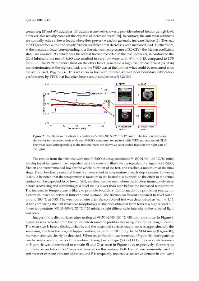
Appl. Sci. 2017, 7, 433 5 of 14
containing EP and AW additives. EP additives are well-known to provide reduced friction at high load;however, this usually comes at the expense of increased wear [28]. In contrast, the anti-wear additivesare normally active at lower loads, where they prevent wear, but generally increase friction [2]. The neatP-SiSO generates a low and steady friction coefficient that decreases with increased load. Furthermore,at the maximum load (corresponding to a Hertzian contact pressure of 3.0 GPa), the friction coefficientstabilizes around 0.90, which was the lowest friction recorded in the test. However, in contrast to theGL-5 lubricant, the neat P-SiSO also resulted in very low wear with WHz < 1.15, compared to 1.75for GL-5. The PFPE reference fluid on the other hand, generated a high friction-coefficient (ca. 0.16)that deteriorated at the highest load, and the WSD was at the limit of what could be measured withthe setup used, WHz > 2.6. This was also in line with the well-known poor boundary lubricationperformance by PFPE that has often been seen in similar tests [15,29,30].
Appl. Sci. 2017, 7, 433 5 of 14
However, in contrast to the GL-5 lubricant, the neat P-SiSO also resulted in very low wear with ��� < 1.15, compared to 1.75 for GL-5. The PFPE reference fluid on the other hand, generated a high friction-coefficient (ca. 0.16) that deteriorated at the highest load, and the WSD was at the limit of what could be measured with the setup used, ��� > 2.6. This was also in line with the well-known poor boundary lubrication performance by PFPE that has often been seen in similar tests [15,29,30].
Figure 2. Results from tribotests at conditions V{100–300 N/25 °C/120 min}. The friction traces are shown for two repeated tests with neat P-SiSO, compared to one test with PFPE and one test of GL-5. The wear scars corresponding to the friction traces are shown as color-coded insets in the right part of the figure.
The results from the tribotest with neat P-SiSO, during conditions V{150 N/40–100 °C/80 min}, are displayed in Figure 3. Two repeated tests are shown to illustrate the repeatability. Again for P-SiSO, friction and wear remained low for the whole duration of the test, and reached a minimum at the final stage. It can be clearly seen that there is an overshoot in temperature at each step increase. However, it should be noted that the temperature is measure in the heated disc support, so the effect in the actual contact can be expected to be lower. Still, an effect can be seen where the friction immediately rises before recovering and stabilizing at a level that is lower than seen before the increased temperature. The increase in temperature is likely to promote boundary film formation by providing energy for a chemical reaction between lubricant and surface. The friction coefficient appeared to level out at around 100 °C at 0.83. The wear parameter after the completed test was determined as ��� ≈ 1.15. When comparing the ball wear scar morphology to the ones obtained from tests at a higher load but lower temperature (V{100–300 N/25 °C/120 min}), a slight difference in intensity of the reflected light was seen.
Figure 3. Results of V{150 N/40–100 °C/80 min} for two repeated tests with neat P-SiSO. Ball wear scars are shown as insets to the right.
Figure 2. Results from tribotests at conditions V{100–300 N/25 ◦C/120 min}. The friction traces areshown for two repeated tests with neat P-SiSO, compared to one test with PFPE and one test of GL-5.The wear scars corresponding to the friction traces are shown as color-coded insets in the right part ofthe figure.
The results from the tribotest with neat P-SiSO, during conditions V{150 N/40–100 ◦C/80 min},are displayed in Figure 3. Two repeated tests are shown to illustrate the repeatability. Again for P-SiSO,friction and wear remained low for the whole duration of the test, and reached a minimum at the finalstage. It can be clearly seen that there is an overshoot in temperature at each step increase. However,it should be noted that the temperature is measure in the heated disc support, so the effect in the actualcontact can be expected to be lower. Still, an effect can be seen where the friction immediately risesbefore recovering and stabilizing at a level that is lower than seen before the increased temperature.The increase in temperature is likely to promote boundary film formation by providing energy fora chemical reaction between lubricant and surface. The friction coefficient appeared to level out ataround 100 ◦C at 0.83. The wear parameter after the completed test was determined as WHz ≈ 1.15.When comparing the ball wear scar morphology to the ones obtained from tests at a higher load butlower temperature (V{100–300 N/25 ◦C/120 min}), a slight difference in intensity of the reflected lightwas seen.
Images of the disc surfaces after testing at V{150 N/40–100 ◦C/80 min} are shown in Figure 4.Figure 4a was recorded from the optical interferometric profilometer using 2.5× optical magnification.The wear scar is barely distinguishable, and the measured surface roughness was approximately thesame magnitude as the original lapped surface, i.e., around 50 nm Ra. In the SEM image (Figure 4b),the wear scar can clearly be detected. When magnification was increased (Figure 4c), dark patchescan be seen covering parts of the surface. Using low voltage (5 keV) EDS, the dark patches seenin Figure 4c was determined to contain Si and O, as seen in Figure 4d,e, respectively. Contrary toour initial expectation, P or S was not detected on this surface. Both P and S are commonly used inanti-wear or extreme pressure additives, and P is frequently reported as an active element in anti-wear
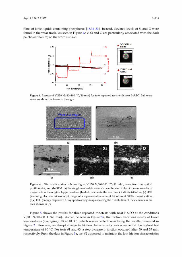
Appl. Sci. 2017, 7, 433 6 of 14
films of ionic liquids containing phosphorus [18,31–33]. Instead, elevated levels of Si and O werefound in the wear track. As seen in Figure 4c–e, Si and O are particularly associated with the darkpatches (tribofilm) on the worn surface.
Appl. Sci. 2017, 7, 433 5 of 14
However, in contrast to the GL-5 lubricant, the neat P-SiSO also resulted in very low wear with ��� < 1.15, compared to 1.75 for GL-5. The PFPE reference fluid on the other hand, generated a high friction-coefficient (ca. 0.16) that deteriorated at the highest load, and the WSD was at the limit of what could be measured with the setup used, ��� > 2.6. This was also in line with the well-known poor boundary lubrication performance by PFPE that has often been seen in similar tests [15,29,30].
Figure 2. Results from tribotests at conditions V{100–300 N/25 °C/120 min}. The friction traces are shown for two repeated tests with neat P-SiSO, compared to one test with PFPE and one test of GL-5. The wear scars corresponding to the friction traces are shown as color-coded insets in the right part of the figure.
The results from the tribotest with neat P-SiSO, during conditions V{150 N/40–100 °C/80 min}, are displayed in Figure 3. Two repeated tests are shown to illustrate the repeatability. Again for P-SiSO, friction and wear remained low for the whole duration of the test, and reached a minimum at the final stage. It can be clearly seen that there is an overshoot in temperature at each step increase. However, it should be noted that the temperature is measure in the heated disc support, so the effect in the actual contact can be expected to be lower. Still, an effect can be seen where the friction immediately rises before recovering and stabilizing at a level that is lower than seen before the increased temperature. The increase in temperature is likely to promote boundary film formation by providing energy for a chemical reaction between lubricant and surface. The friction coefficient appeared to level out at around 100 °C at 0.83. The wear parameter after the completed test was determined as ��� ≈ 1.15. When comparing the ball wear scar morphology to the ones obtained from tests at a higher load but lower temperature (V{100–300 N/25 °C/120 min}), a slight difference in intensity of the reflected light was seen.
Figure 3. Results of V{150 N/40–100 °C/80 min} for two repeated tests with neat P-SiSO. Ball wear scars are shown as insets to the right.
Figure 3. Results of V{150 N/40–100 ◦C/80 min} for two repeated tests with neat P-SiSO. Ball wearscars are shown as insets to the right.
Appl. Sci. 2017, 7, 433 6 of 14
Images of the disc surfaces after testing at V{150 N/40–100 °C/80 min} are shown in Figure 4. Figure 4a was recorded from the optical interferometric profilometer using 2.5× optical magnification. The wear scar is barely distinguishable, and the measured surface roughness was approximately the same magnitude as the original lapped surface, i.e., around 50 nm Ra. In the SEM image (Figure 4b), the wear scar can clearly be detected. When magnification was increased (Figure 4c), dark patches can be seen covering parts of the surface. Using low voltage (5 keV) EDS, the dark patches seen in Figure 4c was determined to contain Si and O, as seen in Figure 4d,e, respectively. Contrary to our initial expectation, P or S was not detected on this surface. Both P and S are commonly used in anti-wear or extreme pressure additives, and P is frequently reported as an active element in anti-wear films of ionic liquids containing phosphorus [18,31–33]. Instead, elevated levels of Si and O were found in the wear track. As seen in Figure 4c–e, Si and O are particularly associated with the dark patches (tribofilm) on the worn surface.
(a) (b)
(c) (d) (e)
Figure 4. Disc surface after tribotesting at V{150 N/40–100 °C/80 min}, seen from (a) optical profilometer; and (b) SEM. (a) the roughness inside wear scar can be seen to be of the same order of magnitude as the original lapped surface; (b) dark patches in the wear track indicate tribofilm; (c) SEM (scanning electron microscopy) image of a representative area of tribofilm at 5000x magnification; (d,e) EDS (energy dispersive X-ray spectroscopy) maps showing the distribution of the elements in the area shown in (c).
Figure 5 shows the results for three repeated tribotests with neat P-SiSO at the conditions V{300 N/40–80 °C/60 min}. As can be seen in Figure 5a, the friction trace was steady at lower temperatures (averaging 0.89 at 40 °C), which was expected considering the results presented in Figure 2. However, an abrupt change in friction characteristics was observed at the highest test temperature of 80 °C. For tests #1 and #3, a step increase in friction occurred after 50 and 55 min, respectively. From the data in Figure 5a, test #2 appeared to maintain the low friction characteristics throughout the test. However, each data point (Figure 5a) is the averaged friction coefficient over 15 s, and examining the friction trace at a higher resolution (15.4 Hz) (Figure 5b) revealed that test #2 also displayed a distinct friction spike during the final minute of the test, indicating a partial seizure. The corresponding ball wear scars are displayed in the insets of Figure 5a and the resulting wear parameters were determined as ��� = 1.96, 1.30, and 1.97, respectively. All wear scars showed significantly different wear scar morphologies compared to previous tests where low friction was maintained throughout: these ball surfaces were clearly abraded and showed higher than average
Figure 4. Disc surface after tribotesting at V{150 N/40–100 ◦C/80 min}, seen from (a) opticalprofilometer; and (b) SEM. (a) the roughness inside wear scar can be seen to be of the same order ofmagnitude as the original lapped surface; (b) dark patches in the wear track indicate tribofilm; (c) SEM(scanning electron microscopy) image of a representative area of tribofilm at 5000x magnification;(d,e) EDS (energy dispersive X-ray spectroscopy) maps showing the distribution of the elements in thearea shown in (c).
Figure 5 shows the results for three repeated tribotests with neat P-SiSO at the conditionsV{300 N/40–80 ◦C/60 min}. As can be seen in Figure 5a, the friction trace was steady at lowertemperatures (averaging 0.89 at 40 ◦C), which was expected considering the results presented inFigure 2. However, an abrupt change in friction characteristics was observed at the highest testtemperature of 80 ◦C. For tests #1 and #3, a step increase in friction occurred after 50 and 55 min,respectively. From the data in Figure 5a, test #2 appeared to maintain the low friction characteristics
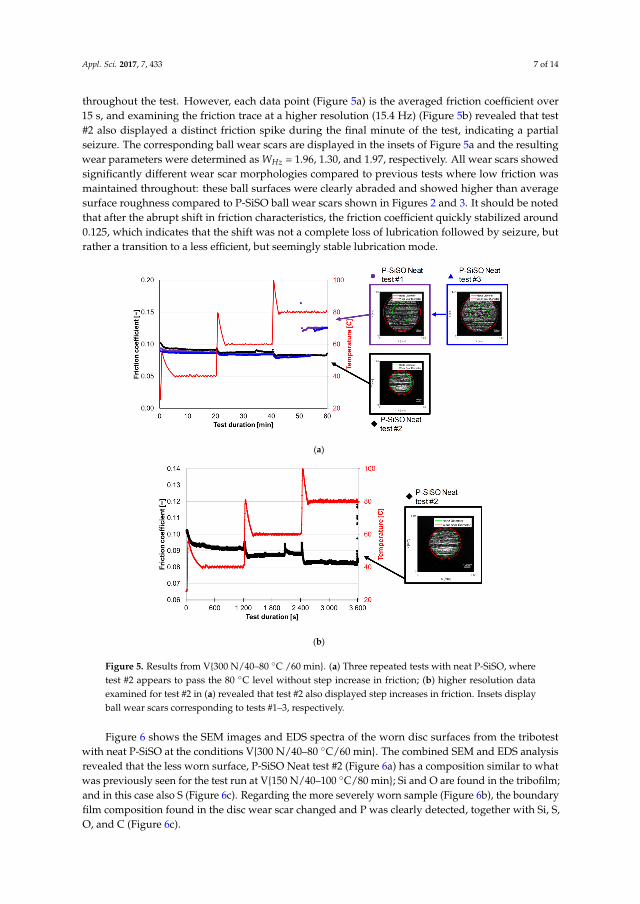
Appl. Sci. 2017, 7, 433 7 of 14
throughout the test. However, each data point (Figure 5a) is the averaged friction coefficient over15 s, and examining the friction trace at a higher resolution (15.4 Hz) (Figure 5b) revealed that test#2 also displayed a distinct friction spike during the final minute of the test, indicating a partialseizure. The corresponding ball wear scars are displayed in the insets of Figure 5a and the resultingwear parameters were determined as WHz = 1.96, 1.30, and 1.97, respectively. All wear scars showedsignificantly different wear scar morphologies compared to previous tests where low friction wasmaintained throughout: these ball surfaces were clearly abraded and showed higher than averagesurface roughness compared to P-SiSO ball wear scars shown in Figures 2 and 3. It should be notedthat after the abrupt shift in friction characteristics, the friction coefficient quickly stabilized around0.125, which indicates that the shift was not a complete loss of lubrication followed by seizure, butrather a transition to a less efficient, but seemingly stable lubrication mode.
Appl. Sci. 2017, 7, 433 7 of 14
surface roughness compared to P-SiSO ball wear scars shown in Figures 2 and 3. It should be noted that after the abrupt shift in friction characteristics, the friction coefficient quickly stabilized around 0.125, which indicates that the shift was not a complete loss of lubrication followed by seizure, but rather a transition to a less efficient, but seemingly stable lubrication mode.
(a)
(b)
Figure 5. Results from V{300 N/40–80 °C /60 min}. (a) Three repeated tests with neat P-SiSO, where test #2 appears to pass the 80 °C level without step increase in friction; (b) higher resolution data examined for test #2 in (a) revealed that test #2 also displayed step increases in friction. Insets display ball wear scars corresponding to tests #1–3, respectively.
Figure 6 shows the SEM images and EDS spectra of the worn disc surfaces from the tribotest with neat P-SiSO at the conditions V{300 N/40–80 °C/60 min}. The combined SEM and EDS analysis revealed that the less worn surface, P-SiSO Neat test #2 (Figure 6a) has a composition similar to what was previously seen for the test run at V{150 N/40–100 °C/80 min}; Si and O are found in the tribofilm; and in this case also S (Figure 6c). Regarding the more severely worn sample (Figure 6b), the boundary film composition found in the disc wear scar changed and P was clearly detected, together with Si, S, O, and C (Figure 6c).
Figure 5. Results from V{300 N/40–80 ◦C /60 min}. (a) Three repeated tests with neat P-SiSO, wheretest #2 appears to pass the 80 ◦C level without step increase in friction; (b) higher resolution dataexamined for test #2 in (a) revealed that test #2 also displayed step increases in friction. Insets displayball wear scars corresponding to tests #1–3, respectively.
Figure 6 shows the SEM images and EDS spectra of the worn disc surfaces from the tribotestwith neat P-SiSO at the conditions V{300 N/40–80 ◦C/60 min}. The combined SEM and EDS analysisrevealed that the less worn surface, P-SiSO Neat test #2 (Figure 6a) has a composition similar to whatwas previously seen for the test run at V{150 N/40–100 ◦C/80 min}; Si and O are found in the tribofilm;and in this case also S (Figure 6c). Regarding the more severely worn sample (Figure 6b), the boundaryfilm composition found in the disc wear scar changed and P was clearly detected, together with Si, S,O, and C (Figure 6c).
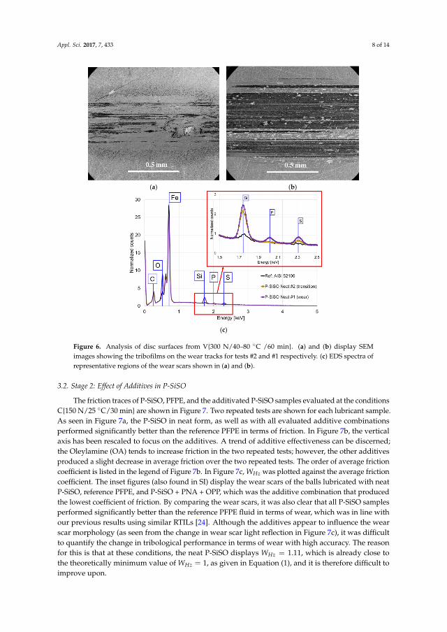
Appl. Sci. 2017, 7, 433 8 of 14
Appl. Sci. 2017, 7, 433 8 of 14
(a) (b)
(c)
Figure 6. Analysis of disc surfaces from V{300 N/40–80 °C /60 min}. (a) and (b) display SEM images showing the tribofilms on the wear tracks for tests #2 and #1 respectively. (c) EDS spectra of representative regions of the wear scars shown in (a) and (b).
3.2. Stage 2: Effect of Additives in P-SiSO
The friction traces of P-SiSO, PFPE, and the additivated P-SiSO samples evaluated at the conditions C{150 N/25 °C/30 min} are shown in Figure 7. Two repeated tests are shown for each lubricant sample. As seen in Figure 7a, the P-SiSO in neat form, as well as with all evaluated additive combinations performed significantly better than the reference PFPE in terms of friction. In Figure 7b, the vertical axis has been rescaled to focus on the additives. A trend of additive effectiveness can be discerned; the Oleylamine (OA) tends to increase friction in the two repeated tests; however, the other additives produced a slight decrease in average friction over the two repeated tests. The order of average friction coefficient is listed in the legend of Figure 7b. In Figure 7c, ��� was plotted against the average friction coefficient. The inset figures (also found in SI) display the wear scars of the balls lubricated with neat P-SiSO, reference PFPE, and P-SiSO + PNA + OPP, which was the additive combination that produced the lowest coefficient of friction. By comparing the wear scars, it was also clear that all P-SiSO samples performed significantly better than the reference PFPE fluid in terms of wear, which was in line with our previous results using similar RTILs [24]. Although the additives appear to influence the wear scar morphology (as seen from the change in wear scar light reflection in Figure 7c), it was difficult to quantify the change in tribological performance in terms of wear with high accuracy. The reason for this is that at these conditions, the neat P-SiSO displays ��� = 1.11, which is already close to the theoretically minimum value of ��� = 1, as given in Equation (1), and it is therefore difficult to improve upon.
Figure 6. Analysis of disc surfaces from V{300 N/40–80 ◦C /60 min}. (a) and (b) display SEMimages showing the tribofilms on the wear tracks for tests #2 and #1 respectively. (c) EDS spectra ofrepresentative regions of the wear scars shown in (a) and (b).
3.2. Stage 2: Effect of Additives in P-SiSO
The friction traces of P-SiSO, PFPE, and the additivated P-SiSO samples evaluated at the conditionsC{150 N/25 ◦C/30 min} are shown in Figure 7. Two repeated tests are shown for each lubricant sample.As seen in Figure 7a, the P-SiSO in neat form, as well as with all evaluated additive combinationsperformed significantly better than the reference PFPE in terms of friction. In Figure 7b, the verticalaxis has been rescaled to focus on the additives. A trend of additive effectiveness can be discerned;the Oleylamine (OA) tends to increase friction in the two repeated tests; however, the other additivesproduced a slight decrease in average friction over the two repeated tests. The order of average frictioncoefficient is listed in the legend of Figure 7b. In Figure 7c, WHz was plotted against the average frictioncoefficient. The inset figures (also found in SI) display the wear scars of the balls lubricated with neatP-SiSO, reference PFPE, and P-SiSO + PNA + OPP, which was the additive combination that producedthe lowest coefficient of friction. By comparing the wear scars, it was also clear that all P-SiSO samplesperformed significantly better than the reference PFPE fluid in terms of wear, which was in line withour previous results using similar RTILs [24]. Although the additives appear to influence the wearscar morphology (as seen from the change in wear scar light reflection in Figure 7c), it was difficultto quantify the change in tribological performance in terms of wear with high accuracy. The reasonfor this is that at these conditions, the neat P-SiSO displays WHz = 1.11, which is already close tothe theoretically minimum value of WHz = 1, as given in Equation (1), and it is therefore difficult toimprove upon.
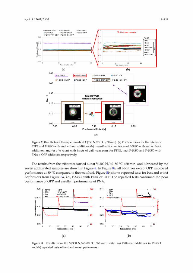
Appl. Sci. 2017, 7, 433 9 of 14
Appl. Sci. 2017, 7, 433 9 of 14
(a) (b)
(c)
Figure 7. Results from the experiments at C{150 N/25 °C /30 min}. (a) Friction traces for the reference PFPE and P-SiSO with and without additives; (b) magnified friction traces of P-SiSO with and without additives; and (c) µ-W chart with insets of ball wear scars for PFPE, neat P-SiSO and P-SiSO with PNA + OPP additives, respectively.
The results from the tribotests carried out at V{300 N/40–80 °C /60 min} and lubricated by the seven additivated samples are shown in Figure 8. In Figure 8a, all additives except OPP improved performance at 80 °C compared to the neat fluid. Figure 8b, shows repeated tests for best and worst performers from Figure 8a, i.e., P-SiSO with PNA or OPP. The repeated tests confirmed the poor performance of OPP and excellent performance of PNA.
(a) (b)
Figure 8. Results from the V{300 N/40–80 °C /60 min} tests. (a) Different additives in P-SiSO; and (b) repeated tests of best and worst performers.
Figure 7. Results from the experiments at C{150 N/25 ◦C /30 min}. (a) Friction traces for the referencePFPE and P-SiSO with and without additives; (b) magnified friction traces of P-SiSO with and withoutadditives; and (c) µ-W chart with insets of ball wear scars for PFPE, neat P-SiSO and P-SiSO withPNA + OPP additives, respectively.
The results from the tribotests carried out at V{300 N/40–80 ◦C /60 min} and lubricated by theseven additivated samples are shown in Figure 8. In Figure 8a, all additives except OPP improvedperformance at 80 ◦C compared to the neat fluid. Figure 8b, shows repeated tests for best and worstperformers from Figure 8a, i.e., P-SiSO with PNA or OPP. The repeated tests confirmed the poorperformance of OPP and excellent performance of PNA.
Appl. Sci. 2017, 7, 433 9 of 14
(a) (b)
(c)
Figure 7. Results from the experiments at C{150 N/25 °C /30 min}. (a) Friction traces for the reference PFPE and P-SiSO with and without additives; (b) magnified friction traces of P-SiSO with and without additives; and (c) µ-W chart with insets of ball wear scars for PFPE, neat P-SiSO and P-SiSO with PNA + OPP additives, respectively.
The results from the tribotests carried out at V{300 N/40–80 °C /60 min} and lubricated by the seven additivated samples are shown in Figure 8. In Figure 8a, all additives except OPP improved performance at 80 °C compared to the neat fluid. Figure 8b, shows repeated tests for best and worst performers from Figure 8a, i.e., P-SiSO with PNA or OPP. The repeated tests confirmed the poor performance of OPP and excellent performance of PNA.
(a) (b)
Figure 8. Results from the V{300 N/40–80 °C /60 min} tests. (a) Different additives in P-SiSO; and (b) repeated tests of best and worst performers. Figure 8. Results from the V{300 N/40–80 ◦C /60 min} tests. (a) Different additives in P-SiSO;and (b) repeated tests of best and worst performers.
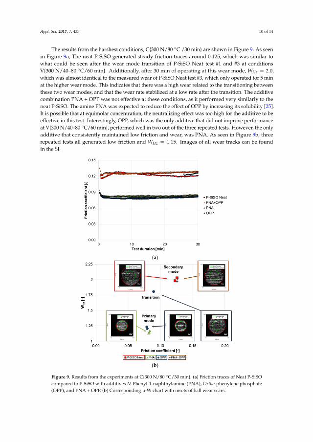
Appl. Sci. 2017, 7, 433 10 of 14
The results from the harshest conditions, C{300 N/80 ◦C /30 min} are shown in Figure 9. As seenin Figure 9a, The neat P-SiSO generated steady friction traces around 0.125, which was similar towhat could be seen after the wear mode transition of P-SiSO Neat test #1 and #3 at conditionsV{300 N/40–80 ◦C/60 min}. Additionally, after 30 min of operating at this wear mode, WHz = 2.0,which was almost identical to the measured wear of P-SiSO Neat test #3, which only operated for 5 minat the higher wear mode. This indicates that there was a high wear related to the transitioning betweenthese two wear modes, and that the wear rate stabilized at a low rate after the transition. The additivecombination PNA + OPP was not effective at these conditions, as it performed very similarly to theneat P-SiSO. The amine PNA was expected to reduce the effect of OPP by increasing its solubility [25].It is possible that at equimolar concentration, the neutralizing effect was too high for the additive to beeffective in this test. Interestingly, OPP, which was the only additive that did not improve performanceat V{300 N/40–80 ◦C/60 min}, performed well in two out of the three repeated tests. However, the onlyadditive that consistently maintained low friction and wear, was PNA. As seen in Figure 9b, threerepeated tests all generated low friction and WHz = 1.15. Images of all wear tracks can be foundin the SI.
Appl. Sci. 2017, 7, 433 10 of 14
The results from the harshest conditions, C{300 N/80 °C /30 min} are shown in Figure 9. As seen in Figure 9a, The neat P-SiSO generated steady friction traces around 0.125, which was similar to what could be seen after the wear mode transition of P-SiSO Neat test #1 and #3 at conditions V{300 N/40–80 °C/60 min}. Additionally, after 30 min of operating at this wear mode, ��� = 2.0, which was almost identical to the measured wear of P-SiSO Neat test #3, which only operated for 5 min at the higher wear mode. This indicates that there was a high wear related to the transitioning between these two wear modes, and that the wear rate stabilized at a low rate after the transition. The additive combination PNA + OPP was not effective at these conditions, as it performed very similarly to the neat P-SiSO. The amine PNA was expected to reduce the effect of OPP by increasing its solubility [25]. It is possible that at equimolar concentration, the neutralizing effect was too high for the additive to be effective in this test. Interestingly, OPP, which was the only additive that did not improve performance at V{300 N/40–80 °C/60 min}, performed well in two out of the three repeated tests. However, the only additive that consistently maintained low friction and wear, was PNA. As seen in Figure 9b, three repeated tests all generated low friction and ��� = 1.15. Images of all wear tracks can be found in the SI.
(a)
(b)
Figure 9. Results from the experiments at C{300 N/80 °C/30 min}. (a) Friction traces of Neat P-SiSO compared to P-SiSO with additives N-Phenyl-1-naphthylamine (PNA), Ortho-phenylene phosphate (OPP), and PNA + OPP. (b) Corresponding µ-W chart with insets of ball wear scars.
SEM images and EDS spectra of the wear track lubricated with P-SiSO + PNA added is shown in Figure 10. EDS analysis was performed on spots both in the center region and at the edge of the wear scar. In the center region of this effective boundary film, the composition was rich in the elements
Figure 9. Results from the experiments at C{300 N/80 ◦C/30 min}. (a) Friction traces of Neat P-SiSOcompared to P-SiSO with additives N-Phenyl-1-naphthylamine (PNA), Ortho-phenylene phosphate(OPP), and PNA + OPP. (b) Corresponding µ-W chart with insets of ball wear scars.
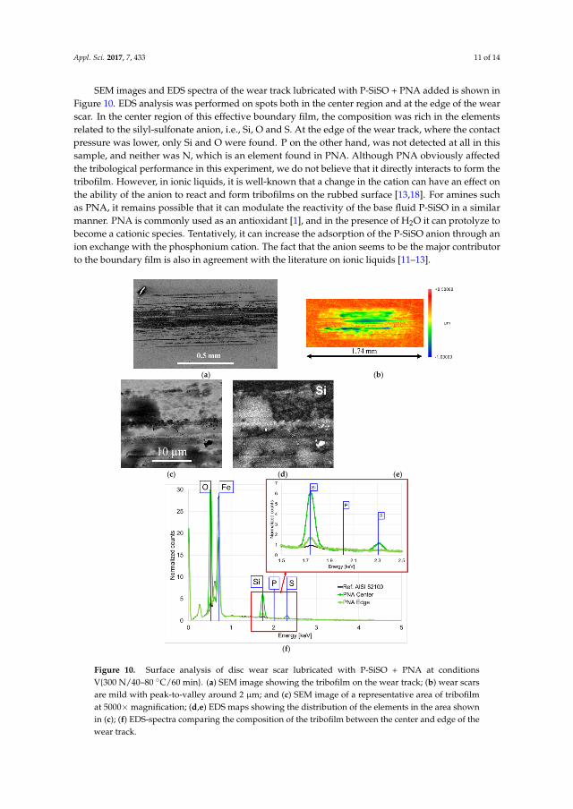
Appl. Sci. 2017, 7, 433 11 of 14
SEM images and EDS spectra of the wear track lubricated with P-SiSO + PNA added is shown inFigure 10. EDS analysis was performed on spots both in the center region and at the edge of the wearscar. In the center region of this effective boundary film, the composition was rich in the elementsrelated to the silyl-sulfonate anion, i.e., Si, O and S. At the edge of the wear track, where the contactpressure was lower, only Si and O were found. P on the other hand, was not detected at all in thissample, and neither was N, which is an element found in PNA. Although PNA obviously affectedthe tribological performance in this experiment, we do not believe that it directly interacts to form thetribofilm. However, in ionic liquids, it is well-known that a change in the cation can have an effect onthe ability of the anion to react and form tribofilms on the rubbed surface [13,18]. For amines suchas PNA, it remains possible that it can modulate the reactivity of the base fluid P-SiSO in a similarmanner. PNA is commonly used as an antioxidant [1], and in the presence of H2O it can protolyze tobecome a cationic species. Tentatively, it can increase the adsorption of the P-SiSO anion through anion exchange with the phosphonium cation. The fact that the anion seems to be the major contributorto the boundary film is also in agreement with the literature on ionic liquids [11–13].
Appl. Sci. 2017, 7, 433 11 of 14
related to the silyl-sulfonate anion, i.e., Si, O and S. At the edge of the wear track, where the contact pressure was lower, only Si and O were found. P on the other hand, was not detected at all in this sample, and neither was N, which is an element found in PNA. Although PNA obviously affected the tribological performance in this experiment, we do not believe that it directly interacts to form the tribofilm. However, in ionic liquids, it is well-known that a change in the cation can have an effect on the ability of the anion to react and form tribofilms on the rubbed surface [13,18]. For amines such as PNA, it remains possible that it can modulate the reactivity of the base fluid P-SiSO in a similar manner. PNA is commonly used as an antioxidant [1], and in the presence of H2O it can protolyze to become a cationic species. Tentatively, it can increase the adsorption of the P-SiSO anion through an ion exchange with the phosphonium cation. The fact that the anion seems to be the major contributor to the boundary film is also in agreement with the literature on ionic liquids [11–13].
(a) (b)
(c) (d) (e)
(f)
Figure 10. Surface analysis of disc wear scar lubricated with P-SiSO + PNA at conditions V{300 N/40–80 °C/ 60 min}. (a) SEM image showing the tribofilm on the wear track; (b) wear scars are mild with peak-to-valley around 2 µm; and (c) SEM image of a representative area of tribofilm at 5000x magnification; (d-e) EDS maps showing the distribution of the elements in the area shown in (c); (f) EDS-spectra comparing the composition of the tribofilm between the center and edge of the wear track.
Figure 10. Surface analysis of disc wear scar lubricated with P-SiSO + PNA at conditionsV{300 N/40–80 ◦C/60 min}. (a) SEM image showing the tribofilm on the wear track; (b) wear scarsare mild with peak-to-valley around 2 µm; and (c) SEM image of a representative area of tribofilmat 5000× magnification; (d,e) EDS maps showing the distribution of the elements in the area shownin (c); (f) EDS-spectra comparing the composition of the tribofilm between the center and edge of thewear track.
Appl. Sci. 2017, 7, 433 12 of 14
4. Conclusions
Based on the work reported in this paper, the following conclusions can be drawn. (1) P-SiSOforms tribologically beneficial boundary films in the conditions evaluated; (2) The elements thatcontributed to the boundary film in the best performing sample correspond to the elements of theanion: Si, S and O. Unexpectedly, Si and O are the most predominant; (3) P-SiSO displayed two distinctlubrication modes: initially low friction and wear, while under increasingly harsh conditions, neatP-SiSO undergoes a shift to a second lubrication mode that is characterized by a transition period ofincreased friction and wear, followed by lubrication at steady friction that is higher than before the shift;(4) After transitioning to the second lubrication mode (with higher friction and wear), the boundaryfilm composition changes to include P, indicating that the cation also reacts with the surface underharsh conditions; (5) The amine type additive PNA (N-Phenyl-1-naphthylamine) successfully preventswear and reduces friction at elevated loads and temperatures. Therefore, the additive extends theenvelope of the optimum lubrication mode of P-SiSO; (6) PNA, as an additive to P-SiSO, promotes theformation of a boundary film composed of Si and O, most likely by an ion exchange that promotes thereactivity of the trimethylsilyl alkylsulfonate anion towards the steel surface.
Supplementary Materials: Supplementary materials are available online at http://www.mdpi.com/2076-3417/7/5/433/s1. Lubricant data regarding P-SiSO and PFPE. Additional tribotest results and surface analysis.
Acknowledgments: This work was funded by the “Austrian COMET-Program” in the frame of K2 XTribology(project No. 849109). The research work was carried out within the Excellence Centre of Tribology (AC2T researchGmbH). The Taiho Kogyo Tribology Research Foundation (TTF) also provided funding through the 2016 15B07grant. Erik Nyberg acknowledges funding from the Graduate School of Space Technology at Luleå Universityof Technology.
Author Contributions: Erik Nyberg performed most of the experiments and analysis and wrote the manuscript.Johanne Mouzon performed SEM-EDS experiments and analysis. Mattias Grahn performed analysis andinterpretation of results. Ichiro Minami conceived and designed the project. All authors have given approval tothe final version of the manuscript.
Conflicts of Interest: The authors declare no conflicts of interest.
Abbreviations
RTIL room-temperature ionic liquidPFPE perfluoropolyetherPNA N-phenyl-1-naphthylamineBHT 2,6-di-tert-butyl-4-methylphenolOA oleylamineDMOP 5,5-dimethyl-1,3,2-dioxaphosphorinan-2-oneOPP ortho-phenylene phosphateWSD wear scar diameterHzD hertzian contact diameterEP extreme pressureAW anti-wearSEM scanning electron microscopyEDS energy dispersive X-ray spectroscopy
References
1. Rudnick, L.R. Lubricant Additives: Chemistry and Applications; Marcel Dekker: New York, NY, USA, 2003.2. Spikes, H. The History and Mechanisms of ZDDP. Tribol. Lett. 2004, 17, 469–489. [CrossRef]3. Forbes, E.S. Antiwear and extreme pressure additives for lubricants. Tribology 1970, 3, 145–152. [CrossRef]4. Zhang, J.; Spikes, H. On the Mechanism of ZDDP Antiwear Film Formation. Tribol. Lett. 2016, 63, 1–15.
[CrossRef]
Appl. Sci. 2017, 7, 433 13 of 14
5. Gosvami, N.N.; Bares, J.A.; Mangolini, F.; Konicek, A.R.; Yablon, D.G.; Carpick, R.W. Mechanisms of antiweartribofilm growth revealed in situ by single-asperity sliding contacts. Science 2015, 348, 102–106. [CrossRef][PubMed]
6. Forbes, E.S. The load-carrying action of organo-sulphur compounds—A review. Wear 1970, 15, 87–96.[CrossRef]
7. Hsu, S.M.; Gates, R.S. Boundary lubricating films: Formation and lubrication mechanism. Tribol. Int. 2005,38, 305–312. [CrossRef]
8. Mortier, R.M.; Fox, M.F.; Orszulik, S.T. Chemistry and Technology of Lubricants, 3rd ed.; Springer: London, UK;New York, NY, USA; Dordrecht, The Netherlands; Heidelberg, Germany, 2010; Volume 3.
9. Rudnick, L.R.; Shubkin, R.L. Synthetic Lubricants and High-performance Functional Fluids, 2nd ed.; CRC Press:New York, NY, USA, 1999; Volume 77.
10. Minami, I.; Mori, S. Concept of molecular design towards additive technology for advanced lubricants.Lubr. Sci. 2007, 19, 127–149. [CrossRef]
11. Bermúdez, M.D.; Jiménez, A.E.; Sanes, J.; Carrión, F.J. Ionic liquids as advanced lubricant fluids. Molecules2009, 14, 2888–2908. [CrossRef] [PubMed]
12. Minami, I. Ionic liquids in tribology. Molecules 2009, 14, 2286–2305. [CrossRef] [PubMed]13. Somers, A.E.; Howlett, P.C.; MacFarlane, D.R.; Forsyth, M. A Review of Ionic Liquid Lubricants. Lubricants
2013, 1, 3–21. [CrossRef]14. Torimoto, T.; Tsuda, T.; Okazaki, K.; Kuwabata, S. New frontiers in materials science opened by ionic liquids.
Adv. Mater. 2010, 22, 1196–1221. [CrossRef] [PubMed]15. Ye, C.; Liu, W.; Chen, Y.; Yu, L. Room-temperature ionic liquids: A novel versatile lubricant. Chem. Commun.
2001, 21, 2244–2245. [CrossRef]16. Deetlefs, M.; Fanselow, M.; Seddon, K.R. Ionic liquids: The view from Mount Improbable. RSC Adv. 2016, 6,
4280–4288. [CrossRef]17. Qu, J.; Chi, M.; Meyer, H.M.; Blau, P.J.; Dai, S.; Luo, H. Nanostructure and Composition of Tribo-Boundary
Films Formed in Ionic Liquid Lubrication. Tribol. Lett. 2011, 43, 205–211. [CrossRef]18. Minami, I.; Inada, T.; Sasaki, R.; Nanao, H. Tribo-Chemistry of Phosphonium-Derived Ionic Liquids.
Tribol. Lett. 2010, 40, 225–235. [CrossRef]19. Kamimura, H.; Chiba, T.; Watanabe, N.; Kubo, T.; Nanao, H.; Minami, I.; Mori, S. Effects of Carboxylic Acids
on Friction and Wear Reducing Properties for Alkylmethylimidazolium Derived Ionic liquids. Tribol. Online2006, 1, 40–43. [CrossRef]
20. Kamimura, H.; Kubo, T.; Minami, I.; Mori, S. Effect and mechanism of additives for ionic liquids as newlubricants. Tribol. Int. 2007, 40, 620–625. [CrossRef]
21. Liu, X.; Zhou, F.; Liang, Y.; Liu, W. Benzotriazole as the additive for ionic liquid lubricant: One pathwaytowards actual application of ionic liquids. Tribol. Lett. 2006, 23, 191–196. [CrossRef]
22. Yu, B.; Zhou, F.; Pang, C.; Wang, B.; Liang, Y.; Liu, W. Tribological evaluation of α, ω-diimidazoliumalkylenehexafluorophosphate ionic liquid and benzotriazole as additive. Tribol. Int. 2008, 41, 797–801. [CrossRef]
23. Minami, I.; Watanabe, N.; Nanao, H.; Mori, S.; Fukumoto, K.; Ohno, H. Aspartic Acid-derived Wear-preventingand Friction-reducing Agents for Ionic Liquids. Chem. Lett. 2008, 37, 300–301. [CrossRef]
24. Nyberg, E.; Respatiningsih, C.Y.; Minami, I. Molecular design of advanced lubricant base fluids:Hydrocarbon-mimicking ionic liquids. RSC Adv. 2017, 7, 6364–6373. [CrossRef]
25. Minami, I.; Kikuta, S.; Okabe, H. Anti-wear and friction reducing additives composed of ortho-phenylenephosphate-amine salts for polyether type base stocks. Tribol. Int. 1998, 31, 305–312. [CrossRef]
26. Wang, Q.J.; Zhu, D. Hertz Theory: Contact of Ellipsoidal Surfaces. In Encyclopedia of Tribology; Wang, Q.J.,Chung, Y.-W., Eds.; Springer: Boston, MA, USA, 2013; pp. 1647–1654.
27. Kalin, M.; Vižintin, J. Use of equations for wear volume determination in fretting experiments. Wear 2000,237, 39–48. [CrossRef]
28. Sakamoto, T.; Uetz, H.; Föhl, J.; Khosrawi, M.A. The reaction layer formed on steel by additives based onsulphur and phosphorus compounds under conditions of boundary lubrication. Wear 1982, 77, 139–157.[CrossRef]
29. Zhu, L.; Chen, L.; Yang, X.; Song, H. Functionalized Ionic Liquids as Lubricants for Steel-Steel Contact.Appl. Mech. Mater. 2012, 138, 630–634. [CrossRef]
Appl. Sci. 2017, 7, 433 14 of 14
30. Jiang, D.; Hu, L.; Feng, D. Crown-type ionic liquids as lubricants for steel-on-steel system. Tribol. Lett. 2011,41, 417–424. [CrossRef]
31. Liu, X.; Zhou, F.; Liang, Y.; Liu, W. Tribological performance of phosphonium based ionic liquids for analuminum-on-steel system and opinions on lubrication mechanism. Wear 2006, 261, 1174–1179. [CrossRef]
32. Weng, L.J.; Liu, X.Q.; Liang, Y.M.; Xue, Q.J. Effect of tetraalkylphosphonium based ionic liquids as lubricantson the tribological performance of a steel-on-steel system. Tribol. Lett. 2007, 26, 11–17. [CrossRef]
33. Mu, Z.; Zhou, F.; Zhang, S.; Liang, Y.; Liu, W. Effect of the functional groups in ionic liquid molecules on thefriction and wear behavior of aluminum alloy in lubricated aluminum-on-steel contact. Tribol. Int. 2005, 38,725–731. [CrossRef]
© 2017 by the authors. Licensee MDPI, Basel, Switzerland. This article is an open accessarticle distributed under the terms and conditions of the Creative Commons Attribution(CC BY) license (http://creativecommons.org/licenses/by/4.0/).