Embed Size (px)
Citation preview

ENGINE LUBRICATION & COOLING SYSTEMS
SECTION LC CONTENTS ENGINE LUBRICATION SYSTEM . . . . . . . . . . . . . LC- 2 ENGINE LUBRICATION SYSTEM - For Turbocharged Models . . . . . LC- 6 ENGINE COOLING SYSTEM . . . . . . . . . . . . . . . . . . . . . . . . . . . . . . . L C - 7 ENGINE COOLING SYSTEM - For Turbocharged Models.. ..................... LC-13 SERVICE DATA AND SPECIFICATIONS (S.D.S) . . . . . . , LC-15 SPECIAL SERVICE TOOLS . . . . . . LC-17

ENGINE LUBRICATION SYSTEM Lubrication Circuit
011 passage
* 1 Addltmal lubrication circuit far turbocharged model '2 Additional 011 cooler for turbo A/T model
SLC729
LC-2

ENGINE LUBRICATION SYSTEM Oil Pressure Check
Be careful not to burn yourself, as the engine and oil may be hot.
1 Warm up engine. 2. Stop engine and remove oil pressure switch
1 3 - 17 N rn
SLC545
3 Install pressure gauge with sealant. 4 Start engine and check oil pressure wlth englne
running under no-load
Approximate dlscharge pressure kPa (kg/cm2, psi) I Engine rpm
1,200
2,000
4,000
196 (2.28)
294 (3,431
392 (4.57)
Oil pressure at idling should be more than 78 kPa (0.8 kg/cm2, 11 psi).
I On - vehicle service)
5. Install oil pressure switch.
: 13. 17 N m (1.3 - 1.7 kgm,9 - 12 ft-lb)
The above table shows data tested when SAE 10W-30 oil is used and oil temperature is between 77 ,and 83°C (171 and 181°F). Slight difference will be found because of oil viscosity or oi l tem- perature. If difference i s extreme, check oi l passage and oil pump for oil leaks.
LC-3

ENGINE LUBRICATION SYSTEM Oil Pump Disassembly and Assembly
I 1. Drain oil 2 Remove oil pan
In case of on-vehicle service, refer to Oil Pan for removal in section EM
3. Remove oil pump assembly
When installing oil pump, apply engine oil to inner and outer gear. Be sure that O-ring is properly fitted on.
- Cover
i ( q l 12-16 (1 2 . 16, 9.121 n N m (kg-m. ft-lbl
SLC936
4 .5 10 4 . 0 5,2 9.3 61
001 pump bo . O - r i n g 0
(0) 16-21 116-21.12-15)
6 3 - 8 3 1 Fm 39-49(4-5,29-361 ' 1064-085.46 6 1 )
011 Itralner
N m lkg-m. ft-lbl SLC759
LC-4
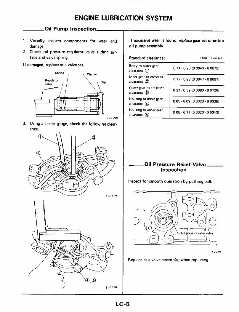
ENGINE LUBRICATION SYSTEM Oil Pump Inspection
1 Visually inspect components for wear and damage
2 Check oil pressure regulator valve sliding sur- face and valve spring
If damaged, replace as a valve set.
SLC295 SLC295
3. Using a feeler gauge, check the following clear- ance.
v SLC549
'0.0 SLC550
If excessive wear is found, replace gear set or entire oil pump assembly.
Standard clearance: Unit m m (in)
I 011 -020(00043-000791 Body to outer gear clearance @
I 0 12.0 23 (0 0047 -0 0091) Inner gear to crescent clearance 0
~
I
0 21 - 0 32 (0 0083.0 0126) Outer gear to crescent clearance @
0 05 - 0 09 (0 0020.0 0035) Housing to inner gear clearance @
I 0 0 5 - 0 1 1 (00020-00043) Housing to outer gear clearance C?
--Oil Pressure Relief Valve Inspection
Inspect for smooth operation by pushing ball.
1- P /- A
SLC551
Replace as a valve assembly, when replacing
LC-5

ENGINE LUBRICATION SYSTEM - For Turbocharged Models
Removal and Installation
OIL DELIVERY SYSTEM
After installation, run engine for a few minutes and check for leaks.
(0.8-1 1.58-80)
(1 5 -20.11.141
To cylinder block
Tooil pan e
1.5 8 - 8 0 )
To cylinder block
Washer 0
l m 8-11 (08-1 1.58-80)
(01 N m (kgm. ft-lb)
SLC983
ENGINE OIL COOLER (A/T models)
Be careful not to burn yourself as engine oil is hot. After installation, run engine for a few minutes and check for oil leaks.
~ ( 9 1 59.74 (6 0 . 7 5.43.54)
Washer 0
011 filter
I bracket -, I Cylinder block
m 14.18 10.131 (1 4. la,
0 8-11 (084.1.5.8-801
011 moler
59.74 I6 0 . 7 5.43 -54)
m 59 -74 (8 0 -7 5.43.54)
(01 N m (kgm. fi-lbl
SLC984
LC-6

ENGINE COOLING SYSTEM Cooling Circuit
To avoid danger of being scalded, never attempt to drain coolant when engine is hot. If it i s necessary t o remove radiator cap when radiator is hot, turn cap slowly counterclockwise t o the f i rs t stop. After all pressure in the cooling system i s released, turn cap past the stop and remove it. Always replace with new gasket and O-ring. Refer t o MA section for changing engine coolant.
Radiator cap Reservoir tank
Thermostat Open
c - Thermostat Closed
Radiator
1
I
ir Water outlet housing
c
Thermostat
Thermostat housing Throttle chamber Turbocharger Air regulator
rurbocharged models only Intake manifold (Water passage)
Cylinder head
SLC728
LC-7

ENGINE COOLING SYSTEM Checking Cooling System
WARNING: Never remove the radiator cap when the engine Is hot; serious burns could be caused by high pressure fluid escaping from the radiator. Wrap a thick cloth around cap and carefully re- move the cap by turning it a quarter turn t o allow built-up pressure to escape and then turn the cap a l l the way off.
CHECKING COOLING SYSTEM HOSES
Check hoses for proper attachment, leaks, cracks, damage, loose connections, chafing and deteriora- tion.
CHECKING COOLING SYSTEM FOR LEAKS
Apply pressure to the cooling system by means of a tester to check for leakage
Testing pressure. 157 kPa (1.6 kg/cm2, 23 psi)
CHECKING RADIATOR 'CAP
Apply pressure to radiator cap by means of a cap tester to see if it is satisfactory.
Radiator cap relief pressure: 78 - 98 kPa (0.8 - 1.0 kg/cm*, 11 - 14 psi)
\ SLC613
LC-8
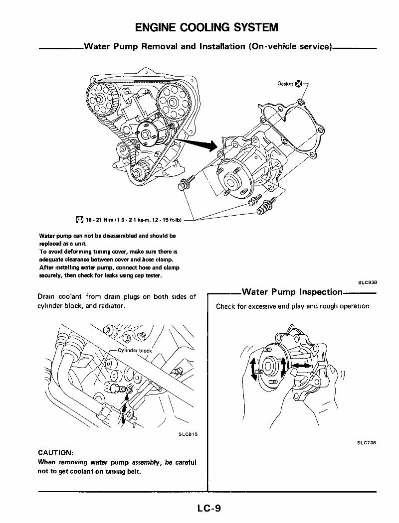
ENGINE COOLING SYSTEM Water Pump Removal and Installation (On-vehicle service)
Water pump can not be disassembled and should be replaced as a unit To avoid deforming timing cover, make sure there IS
adequate clearance between cover and hose clamp. After installing water pump, connect h o e and clamp securely, then check for leaks unng cap tester.
Drain coolant from drain plugs on both sides of cylinder block, and radiator.
SLC815
CAUTION: When removing water pump assembly, be careful not to get coolant on timing belt.
SLC938
--Water Pump Inspection
Check for excessive end play and rough operation
SLC738
LC-9

ENGINE COOLING SYSTEM Thermostat Description (Bottom by-pass coolant flow)
Thermostat Removal and Installation
CAUTION: Drain coolant from drain cocks on cylinder block side and radiator. Remove radiator shroud, cooling fan and water wCtlon pipe securing bolt, then remove thermostat. After installation, run engine for a few minutes, and check for leaks.
L m 16-21 N m ( l 6 - 2 1 kg.m.12-15ft-lbl
SLC939
LC-10

ENGINE COOLING SYSTEM Thermost:
1. Check for valve seating condition at ordinary temperatures I t should seat tightly
2. Check valve opening temperature and maxi- mum valve lift
Standard
76 5 (170) Valve opening temperature
'C ( O F )
I 10/90 (0 39/194) Maximum valve lift
mm/'C (in/"F)
I I
SLC343
3. Then check if valve closes at 5°C (9°F) below valve opening temperature.
Radiator Removal and Installation Before removing radiator, remove front bumper assembly. When filling radiator with coolant, refer to MA section.
3 - 4 1 0 3 - 0 4 . 2 2 - 2 9 )
Reservoir tank
(01 1 8 - 2 1 I1 6 . 2 1.12.16)
Water inlet [Thermostat housing)
Mounting rubber
Clamp (01 3 - 5 ( 0 3 - 0 5 , 2 2 - 3 8 1 N m (kgm, ft-lb)
SLC985
LC-11
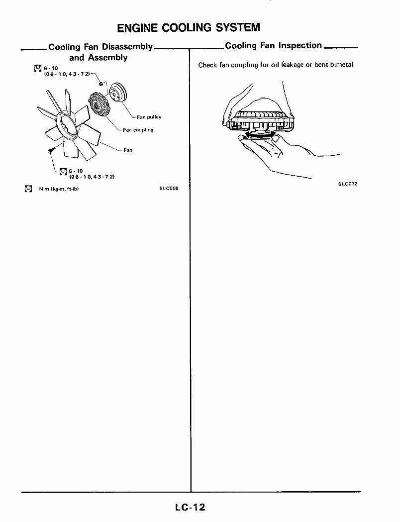
ENGINE COOLING SYSTEM Cooling Fan Disassembly
and Assembly O s - 1 0
IO6 - 1 0,4 3.7 2 1 7
L(c16-10 IO 6 .10 ,4 3.7 21
(c1 N m Ikg-m.ft-lbl SLC558
Cooling Fan Inspection
Check fan coupling for oil leakage or bent bimetal
SLC072 \
LC-12

ENGINE COOLING SYSTEM-For Turbocharged Models Electric Cooling Fan Removal and Installation
Alr conditioner condenser7
-Water Temperature Switch - Inspection
Check water temperature switch for proper opera- tion
Operating temperature: O F F -t ON 100°C ( 2 1 2 ° F )
N rn (kg-m, ft-lb)
SLC559
SEF7388
LC-13

ENGINE COOLING SYSTEM-For Turbocharged Models Coolant Delivery System Removal and Installation
After installation, run engine for a few minutes and check for leaks.
t4 L ( 9 ) 8 . 1 1 1 0 8 . 1 1 , 5 8 . 8 0 1
(9) N rn Ikg-m, ft-lbl
SLC986
LC-14

SERVICE DATA AND SPECIFICATIONS (S.D.S.) Engine Lubrication System
Od pressure check
Approximate discharge pressure kPa (kglcm', psi1
Engine rpm
Idle speed
1,200
2,000
4,000
78 (0 8.111
196 (2.281
294 13.43)
392 (4,571
Oil pump
INNER GEAR SLC573
Unit mm (in)
OUTER GEAR
Height H I H* Except turbo model 12 5 104921 18 5 (0 7281 Turbo madel 15 5 (0 6101 21 5 10 8461
Unit mm (in1
0 11 . O 20 IOOM3 - 0 00791 Body to outer gear clearance @ Inner gear to crescent clearance @ Outer gear to crescent clearance @ Hawing t o inner gear clearance @ Housing to outer gear clearance 0
0 12.0 23 10 OM7 - 0 00911
0 21 - 0 32 100083 - 0 01261
0 0 5 - 0 0 9 (00020-000351
0 05.0 11 (0 0020.0 00431
Oil pressure regulator valve
Openlng pressure 373-412 kPa (kglcm', psil lrpm 13 8 . 4 2,54.601/2.000
Tightening torque - U"lt N m kg-m ft-lb
011 pump secumg bolt Ml5
M,3
011 pump cover screw
Regulator valve cap bol t
011 ~ t i a m e r bolt M6
ME
011 pressure switch
Turbccharger 0 1 1 inlet tube to cylinder black
0 1 1 inlet tube t o tun bocharger
011 outlet pipe to tu, bocharger
Engine 011 cooler 011 filter bracket t o cylinder block
011 filterstud
011 cooler tube to 011
filrer bracket
011 Cooler
6 - 7
12 - 16
4 - 5
39 -49
6 3 - 8 3
16-21
13-17
15 20
8-11
8 11
14.18
59 74
59 - 74
8 -11
0 6 - 0 7 4 3 - 5 1
1 2 - 1 6 9 - 1 2
0 4 - 0 5 2 9 - 3 6
4 - 5 29-36
0 6 4 - 0 8 5 4 6 - 6 1
1 6 - 2 1
1 3 - 1 7
1 5 - 2 0
0 8 - 1 1
0 8 - 1 1
1 4 1 8
6 0 - 7 5
6 0 - 7 5
0 8 - 1 1
12.15
9 -12
11 - 14
5 8 - 8 0
5 8 - 8 0
10-13
43.54
43.54
5 8 - 8 0
LC-15
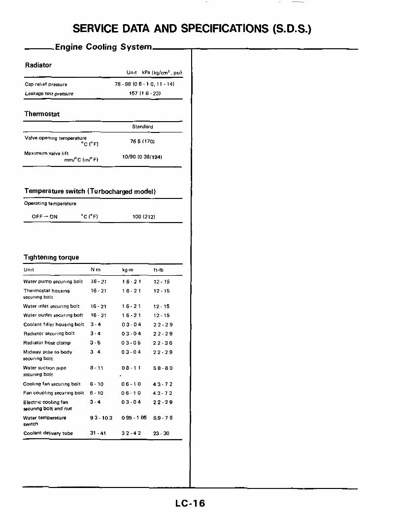
SERVICE DATA AND SPECIFICATIONS (S.D.S.) Engine Cooling System
Radiator Unit kPa lkg/cm'. psd
Cap relief pressure 78-98108-10.11 -141
Leakage test ~rerrure 157 I1 6 -23) - ~~
Thermostat
Standard
765 (170) Valve opening temperature
Maximum valve I!ft
'C 1°F)
mmPC IinPF) 10/90 IO 39/194) ~
Temperature switch (Turbocharged model)
Operatmg temperature
OFF - ON 'C 1°F) 100 1212)
Tightening torque
U"lt N m kg-m f t - lb
Water PumD recurmg bolt
Thermostat housing securing bol t
Water inlet securing bol t
water outlet securing bol t
Coolant fil ler housing bol t
Radiator securtng bolt
Radiator hose clamp
Midwav pipe to body securing bol t
Water suction p ~ p e securing bol t
Coolmg fan recurmg bolt
Fan coup11ng recuring bolt
Electric molmgfan recuring bolt and nut
water temperature w i t c h
Coolant delivelv tube
16-21
16-21
16-21 16.21 3-4
3-4
3-5
3 4
8-11
6- 10 6-10 3 - 4
93-103
31 -41
16-21
16-21
16-21 16-21
03-04
03-04
03-05
03-04
08-1 1
05-10 06-10
03-04
095-1 05
32-42
12- 15
12- 15
12- 15 12-15
22-29
22-29 22-36
22-29
5 8 - 8 0
43-72 43-12
22-29
6.9 - 7 6
23 - 30
LC-16

SPECIAL SERVICE TOOLS
Tool number (Kent-Moore No )
ST25051001 (J25695-1)
ST25052000 (J25695-2)
EG17650301 ( - )
Tool name
~~~
Oi l pressure gauge
Hose
Radiator cap tester adapter
LC-17

Courtesy Nissan 1777 North Central Expressway Richardson, TX 75080 (800)527-1909
NISSAN FACTORY SERVICE MANUAL CDROM END-USER LICENSE AGREEMENT NOTICE TO USER: THIS IS A CONTRACT. BY PURCHASING AND USING THE SERVICE MANUAL ON CDROM, YOU ACCEPT ALL THE TERMS AND CONDITIONS OF THIS AGREEMENT. This End User License Agreement accompanies the Service Manual on CDROM product and related explanatory materials. Please read this Agreement carefully. By purchasing and using the Service Manual on CDROM, you are implying that you have carefully read, agree with, and will adhere to the conditions set forth in this agreement. If you do not wish to accept the terms of this End User Agreement please do not use the Service Manual on CDROM. You will not be permitted to use the Service Manual on CDROM without consenting to this end user agreement. Upon your acceptance of this Agreement, Courtesy Nissan grants to you a nonexclusive license to use the Service Manual on CDROM, provided that you agree to the following: USE OF SOFTWARE You may install the contents of the CD on a hard disk or other storage device for personal use only. Each Service Manual on CDROM comes with a single user license. Under no circumstances should the contents of the Service Manual CDROM be placed on a server for purposes of distributing or allowing access to the material over a network. COPYRIGHT AND TRADEMARK RIGHTS The Service Manual CDROM is owned by Courtesy Nissan and its structure and organization, all graphics and coding are considered intellectual property of Courtesy Nissan. The Service Manual on CDROM is also protected by United States Copyright Law and International Treaty provisions. This Agreement does not grant you any intellectual property or resale rights to the Service Manual CDROM. RESTRICTIONS You agree not to modify, adapt, translate, reverse engineer, decompile or disassemble the PDF file on the Service Manual CDROM. The Service Manual on CDROM is licensed and distributed by Courtesy Nissan for single user utilization of its contents only. Licensed users will be permitted to use the contents of the Service Manual CDROM for multimedia presentation to an audience from a single machine using a large display or projection device but the Service Manual CDROM may not otherwise be distributed, sold to or made accessible to multiple users. NO WARRANTY The software is being delivered to you AS IS and Courtesy Nissan makes no warranty as to its use or performance. COURTESY NISSAN DOES NOT AND CANNOT WARRANT THE PERFORMANCE OR RESULTS YOU MAY OBTAIN BY USING THE SERVICE MANUAL CDROM OR DOCUMENTATION, NOR MAKES ANY WARRANTIES, EXPRESS OR IMPLIED, AS TO NONINFRINGEMENT OF THIRD-PARTY RIGHTS, MERCHANTABILITY, OR FITNESS FOR ANY PARTICULAR PURPOSE. IN NO EVENT WILL COURTESY NISSAN BE LIABLE TO YOU FOR ANY CONSEQUENTIAL, INCIDENTAL, OR SPECIAL DAMAGES FOR ANY REASON.

Courtesy Nissan 1777 North Central Expressway Richardson, TX 75080 (800)527-1909
GOVERNING LAW AND GENERAL PROVISIONS This Agreement will be governed by the laws of the State of Texas, USA, excluding the application of its conflicts of law rules. This Agreement will not be governed by the United Nations Convention on Contracts for the International Sale of Goods, the application of which is expressly excluded. If any part of this Agreement is found void and unenforceable, it will not affect the validity of the balance of the Agreement, which shall remain valid and enforceable according to its terms. You agree that the Service Manual on CDROM will not be shipped, transferred or exported into any country or used in any manner prohibited by the United States Export Administration act or any other export laws, restrictions or regulations. This Agreement shall automatically terminate upon failure by you to comply with its terms. This Agreement may only be modified in writing signed by and authorized officer for Courtesy Nissan. Courtesy Nissan 1777 North Central Expressway Richardson, TX 75080 USA YOUR ACCEPTANCE OF THE FOREGOING AGREEMENT IS IMPLIED UPON PURCHASING AND USING THE SERVICE MANUAL CDROM.