Embed Size (px)
Citation preview
1
The LubeCoach Decision Parameters
Mike Johnson, President
Advanced Machine Reliability Resources, Inc. www.PrecisionLubrication.com
Bearing manufacturers have provided a significant amount of detailed advice for lubricant selection, application and replenishment. Formulas used by the machine designers incorporate details that are typically not readily available to the maintenance practitioner, namely load rating and ratio, grease L10 lifecycle, and specific bearing dimensions. The bearing diameters (OD, ID) may be satisfactorily estimated, but there are multiple bearing models for a bearing type that will share a bore dimension. Without the correct bore and outer diameter it is impossible to arrive at an exact replacement volume. Grease viability drives replacement frequency. Grease Viability is best determined by testing. Per DIN 51825, greases can be evaluated under laboratory conditions to deliver a provisional expected lifecycle, with results reported in either L10 or L50 values. The grease’s L10 and L50 values depict operating hours to 90% and 50% viability. Grease viability is determined by frictional measurement of a loaded bearing in the FE8 test stand. When the grease can no longer separate and protect surfaces during test conditions it is evidenced by an increase in friction beyond a threshold. At this point the test hours are noted and the grease is assigned a value in hours for grease viability. These values are not often published for customer use. Without these discrete pieces of information for the greased bearing, estimating the best replacement frequency is challenging. If the machine owner wants to use machine lubrication as a leading practice to improve machine reliability, then the machine owner must invest time to fully define the bearing and lubricant details in order to calculate appropriate volumes and intervals to deliver reliability centric lubrication practices. This paper presents the engineering principles for bearing grease relubrication, including consideration for open, single, and double shielded bearing configurations, and will include both theoretical methods and general advice useful to calculate both volumes and intervals when the exact details are not available. The calculations presented here are also used to define volume and frequency for operating conditions.
2
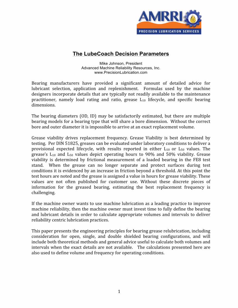
Bearing manufacturers have provided detailed advice for selecting lubricant type, volume and frequency requirements. Their intent is to assist the user with placing the optimum volume of a lubricant product with viscometric properties and surface performance (AW and EP) additives that precisely address the operating parameters (heat, load, vibration, moisture, contaminant, process chemical challenges). Once accomplished, the user can expect the grease to feed oil to the race incrementally between the current date and the planned replenishment date so that the replacement practice provides a seamless flow of lubricant to the load zone, as depicted in Figure 1. Either too much or too little grease, and/or inappropriately high or low oil viscosity causes viscous drag and/or destruction of the bearing surfaces and lubricant within the bearing. In moderate and high speed bearings (nDm > 150K) even slight variations in consistency of replenishment and fill volume produces effects including dry surfaces and elevated high-‐frequency vibration (inadequate feed), elevated temperatures and increased energy consumption (overfeed). The faster the shaft speed, and the higher the load, the more pronounced the deficiencies. As the shaft speed decreases the negative impact (churning, overheating, and energy losses) declines, but is still evident. The first part of this multi-‐part document addresses lubricant viscosity and NLGI selection. The second part addresses volume and frequency. The third part addresses sealed and shielded bearings and electric motor configurations. Lubricant Selection – Base Oil Viscosity, Additive Type, NLGI Grade Viscosity changes with temperature and pressure. As temperature increases, viscosity decreases, and as pressure increases, viscosity increases. These factors are
Figure 1. Planned Benefit of Well Defined Volume and Replacement Intervals
3
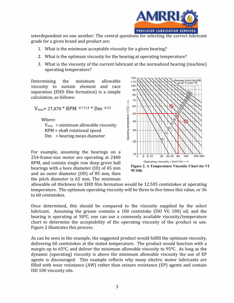
interdependent on one another. The central questions for selecting the correct lubricant grade for a given brand and product are:
1. What is the minimum acceptable viscosity for a given bearing?
2. What is the optimum viscosity for the bearing at operating temperature? 3. What is the viscosity of the current lubricant at the normalized bearing (machine)
operating temperature? Determining the minimum allowable viscosity to sustain element and race separation (EHD film formation) is a simple calculation, as follows: Vmin= 27,878 * RPM -‐0.7114 * Dm -‐0.52
Where: Vmin = minimum allowable viscosity RPM = shaft rotational speed Dm = bearing mean diameter
For example, assuming the bearings on a 254-‐frame-‐size motor are operating at 2400 RPM, and contain single row deep grove ball bearings with a bore diameter (ID) of 45 mm and an outer diameter (OD) of 85 mm, then the pitch diameter is 65 mm. The minimum allowable oil thickness for EHD film formation would be 12.505 centistokes at operating temperature. The optimum operating viscosity will be three to five times this value, or 36 to 60 centistokes. Once determined, this should be compared to the viscosity supplied by the select lubricant. Assuming the grease contains a 100 centistoke (ISO VG 100) oil, and the bearing is operating at 500C, one can use a commonly available viscosity/temperature chart to determine the acceptability of the operating viscosity of the product in use. Figure 2 illustrates this process. As can be seen in the example, the suggested product would fulfill the optimum viscosity, delivering 60 centistokes at the stated temperature. The product would function with a margin up to 650C, and deliver the minimum allowable viscosity to 950C. As long as the dynamic (operating) viscosity is above the minimum allowable viscosity the use of EP agents is discouraged. This example reflects why many electric motor lubricants are filled with wear resistance (AW) rather than seizure resistance (EP) agents and contain ISO 100 viscosity oils.
Figure 2. A Temperature Viscosity Chart for VI 95 Oils
4
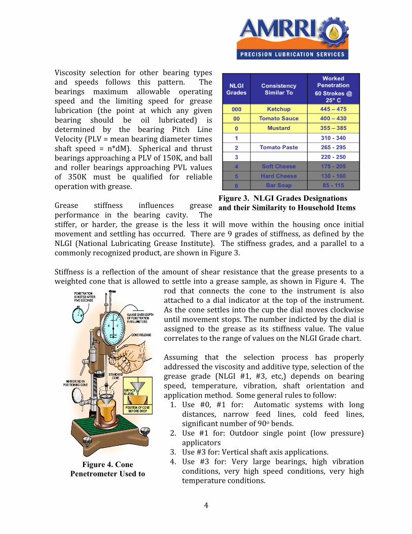
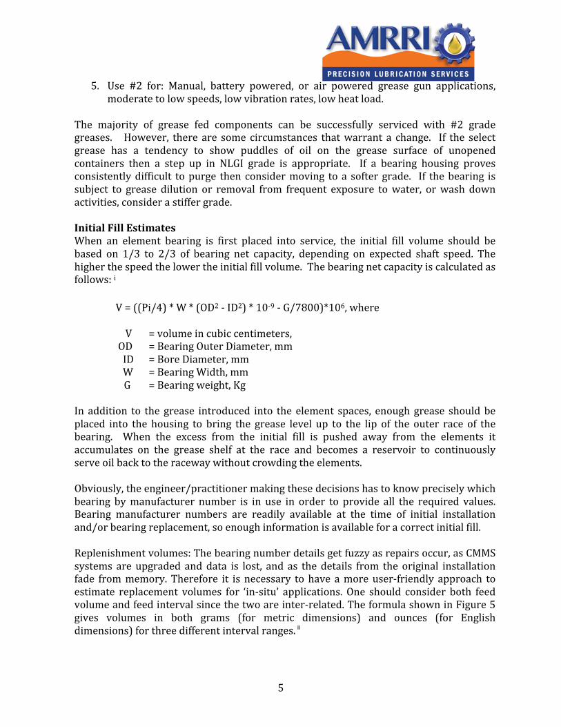
Viscosity selection for other bearing types and speeds follows this pattern. The bearings maximum allowable operating speed and the limiting speed for grease lubrication (the point at which any given bearing should be oil lubricated) is determined by the bearing Pitch Line Velocity (PLV = mean bearing diameter times shaft speed = n*dM). Spherical and thrust bearings approaching a PLV of 150K, and ball and roller bearings approaching PVL values of 350K must be qualified for reliable operation with grease. Grease stiffness influences grease performance in the bearing cavity. The stiffer, or harder, the grease is the less it will move within the housing once initial movement and settling has occurred. There are 9 grades of stiffness, as defined by the NLGI (National Lubricating Grease Institute). The stiffness grades, and a parallel to a commonly recognized product, are shown in Figure 3. Stiffness is a reflection of the amount of shear resistance that the grease presents to a weighted cone that is allowed to settle into a grease sample, as shown in Figure 4. The
rod that connects the cone to the instrument is also attached to a dial indicator at the top of the instrument. As the cone settles into the cup the dial moves clockwise until movement stops. The number indicted by the dial is assigned to the grease as its stiffness value. The value correlates to the range of values on the NLGI Grade chart. Assuming that the selection process has properly addressed the viscosity and additive type, selection of the grease grade (NLGI #1, #3, etc,) depends on bearing speed, temperature, vibration, shaft orientation and application method. Some general rules to follow: 1. Use #0, #1 for: Automatic systems with long
distances, narrow feed lines, cold feed lines, significant number of 90o bends.
2. Use #1 for: Outdoor single point (low pressure) applicators
3. Use #3 for: Vertical shaft axis applications. 4. Use #3 for: Very large bearings, high vibration
conditions, very high speed conditions, very high temperature conditions.
Figure 4. Cone Penetrometer Used to
Set NLGI Grades
Figure 3. NLGI Grades Designations and their Similarity to Household Items
5
5. Use #2 for: Manual, battery powered, or air powered grease gun applications, moderate to low speeds, low vibration rates, low heat load.
The majority of grease fed components can be successfully serviced with #2 grade greases. However, there are some circumstances that warrant a change. If the select grease has a tendency to show puddles of oil on the grease surface of unopened containers then a step up in NLGI grade is appropriate. If a bearing housing proves consistently difficult to purge then consider moving to a softer grade. If the bearing is subject to grease dilution or removal from frequent exposure to water, or wash down activities, consider a stiffer grade. Initial Fill Estimates When an element bearing is first placed into service, the initial fill volume should be based on 1/3 to 2/3 of bearing net capacity, depending on expected shaft speed. The higher the speed the lower the initial fill volume. The bearing net capacity is calculated as follows: i
V = ((Pi/4) * W * (OD2 -‐ ID2) * 10-‐9 -‐ G/7800)*106, where V = volume in cubic centimeters, OD = Bearing Outer Diameter, mm ID = Bore Diameter, mm W = Bearing Width, mm G = Bearing weight, Kg
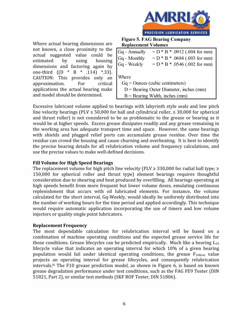
In addition to the grease introduced into the element spaces, enough grease should be placed into the housing to bring the grease level up to the lip of the outer race of the bearing. When the excess from the initial fill is pushed away from the elements it accumulates on the grease shelf at the race and becomes a reservoir to continuously serve oil back to the raceway without crowding the elements. Obviously, the engineer/practitioner making these decisions has to know precisely which bearing by manufacturer number is in use in order to provide all the required values. Bearing manufacturer numbers are readily available at the time of initial installation and/or bearing replacement, so enough information is available for a correct initial fill. Replenishment volumes: The bearing number details get fuzzy as repairs occur, as CMMS systems are upgraded and data is lost, and as the details from the original installation fade from memory. Therefore it is necessary to have a more user-‐friendly approach to estimate replacement volumes for ‘in-‐situ’ applications. One should consider both feed volume and feed interval since the two are inter-‐related. The formula shown in Figure 5 gives volumes in both grams (for metric dimensions) and ounces (for English dimensions) for three different interval ranges. ii
6
Where actual bearing dimensions are not known, a close proximity to the actual suggested value could be estimated by using housing dimensions and factoring again by one-‐third {(D * B * .114) *.33}. CAUTION: This provides only an approximation. For critical applications the actual bearing make and model should be determined. Excessive lubricant volume applied to bearings with labyrinth style seals and low pitch line velocity bearings (PLV ≤ 50,000 for ball and cylindrical roller, ≤ 30,000 for spherical and thrust roller) is not considered to be as problematic to the grease or bearing as it would be at higher speeds. Excess grease dissipates readily and any grease remaining in the working area has adequate transport time and space. However, the same bearings with shields and plugged relief ports can accumulate grease residue. Over time the residue can crowd the housing and cause churning and overheating. It is best to identify the precise bearing details for all relubrication volume and frequency calculations, and use the precise values to make well-‐defined decisions. Fill Volume for High Speed Bearings The replacement volume for high pitch line velocity (PLV ≥ 330,000 for radial ball type; ≥ 150,000 for spherical roller and thrust type) element bearings requires thoughtful consideration due to shearing and heat produced by overfilling. All bearings operating at high speeds benefit from more frequent but lower volume doses, emulating continuous replenishment that occurs with oil lubricated elements. For instance, the volume calculated for the short interval, Gq-‐Weekly, would ideally be uniformly distributed into the number of working hours for the time period and applied accordingly. This technique would require automatic application incorporating the use of timers and low volume injectors or quality single point lubricators. Replacement Frequency The most dependable calculation for relubrication interval will be based on a combination of machine operating conditions and the expected grease service life for those conditions. Grease lifecycles can be predicted empirically. Much like a bearing L10 lifecycle value that indicates an operating interval for which 10% of a given bearing population would fail under identical operating conditions, the grease F10Real value projects an operating interval for grease lifecycles, and consequently relubrication intervals.iii The F10 grease prediction model, as shown in Figure 6, is based on known grease degradation performance under test conditions, such as the FAG FE9 Tester (DIN 51821, Part 2), or similar test methods (SKF ROF Tester, DIN 51806).
Gq - Annually = D * B * .0912 (.004 for mm)Gq - Monthly = D * B * .0684 (.003 for mm)Gq - Weekly = D * B * .0546 (.002 for mm)
Where Gq = Ounces (cubic centimeters) D = Bearing Outer Diameter, inches (mm) B = Bearing Width, inches (mm)
Figure 5. FAG Bearing Company Replacement Volumes
7
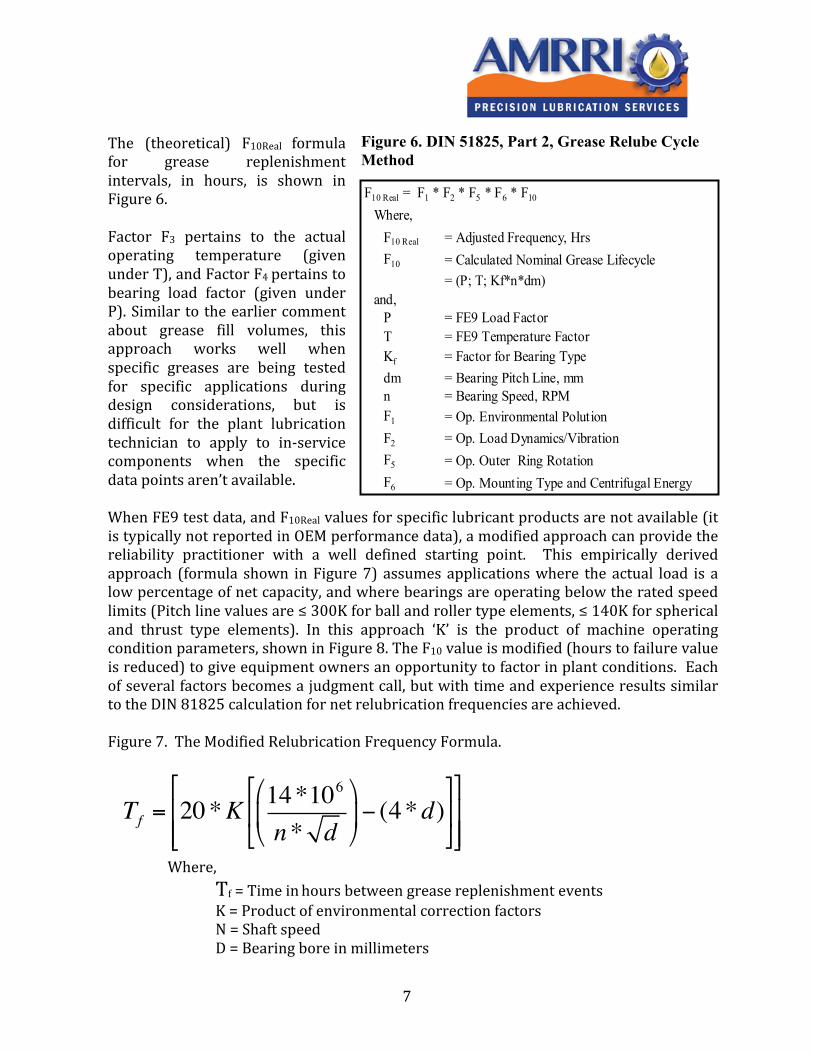
The (theoretical) F10Real formula for grease replenishment intervals, in hours, is shown in Figure 6. Factor F3 pertains to the actual operating temperature (given under T), and Factor F4 pertains to bearing load factor (given under P). Similar to the earlier comment about grease fill volumes, this approach works well when specific greases are being tested for specific applications during design considerations, but is difficult for the plant lubrication technician to apply to in-‐service components when the specific data points aren’t available. When FE9 test data, and F10Real values for specific lubricant products are not available (it is typically not reported in OEM performance data), a modified approach can provide the reliability practitioner with a well defined starting point. This empirically derived approach (formula shown in Figure 7) assumes applications where the actual load is a low percentage of net capacity, and where bearings are operating below the rated speed limits (Pitch line values are ≤ 300K for ball and roller type elements, ≤ 140K for spherical and thrust type elements). In this approach ‘K’ is the product of machine operating condition parameters, shown in Figure 8. The F10 value is modified (hours to failure value is reduced) to give equipment owners an opportunity to factor in plant conditions. Each of several factors becomes a judgment call, but with time and experience results similar to the DIN 81825 calculation for net relubrication frequencies are achieved. Figure 7. The Modified Relubrication Frequency Formula.
Tf = 20*K 14*106
n* d!
"#
$
%&− (4*d)
(
)*
+
,-
(
)**
+
,--
Where, Tf = Time in hours between grease replenishment events K = Product of environmental correction factors N = Shaft speed D = Bearing bore in millimeters
F10 Real = F1 * F2 * F5 * F6 * F10
Where,F10 Real = Adjusted Frequency, HrsF10 = Calculated Nominal Grease Lifecycle
= (P; T; Kf*n*dm)and,
P = FE9 Load FactorT = FE9 Temperature FactorKf = Factor for Bearing Typedm = Bearing Pitch Line, mmn = Bearing Speed, RPMF1 = Op. Environmental PolutionF2 = Op. Load Dynamics/VibrationF5 = Op. Outer Ring RotationF6 = Op. Mounting Type and Centrifugal Energy
Figure 6. DIN 51825, Part 2, Grease Relube Cycle Method
8
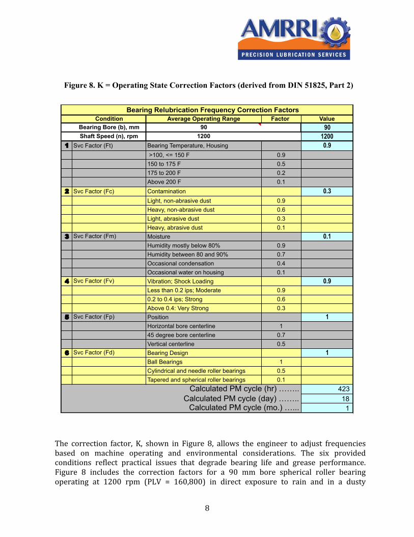
The correction factor, K, shown in Figure 8, allows the engineer to adjust frequencies based on machine operating and environmental considerations. The six provided conditions reflect practical issues that degrade bearing life and grease performance. Figure 8 includes the correction factors for a 90 mm bore spherical roller bearing operating at 1200 rpm (PLV = 160,800) in direct exposure to rain and in a dusty
Figure 8. K = Operating State Correction Factors (derived from DIN 51825, Part 2)
Condition Average Operating Range Factor Value Bearing Bore (b), mm 90 90 Shaft Speed (n), rpm 1200 12001 Svc Factor (Ft) Bearing Temperature, Housing 0.9
>100, <= 150 F 0.9 150 to 175 F 0.5
175 to 200 F 0.2Above 200 F 0.1
2 Svc Factor (Fc) Contamination 0.3Light, non-abrasive dust 0.9
Heavy, non-abrasive dust 0.6Light, abrasive dust 0.3Heavy, abrasive dust 0.1
3 Svc Factor (Fm) Moisture 0.1Humidity mostly below 80% 0.9
Humidity between 80 and 90% 0.7Occasional condensation 0.4Occasional water on housing 0.1
4 Svc Factor (Fv) Vibration; Shock Loading 0.9Less than 0.2 ips; Moderate 0.9
0.2 to 0.4 ips; Strong 0.6Above 0.4: Very Strong 0.3
5 Svc Factor (Fp) Position 1Horizontal bore centerline 1
45 degree bore centerline 0.7Vertical centerline 0.5
6 Svc Factor (Fd) Bearing Design 1Ball Bearings 1
Cylindrical and needle roller bearings 0.5Tapered and spherical roller bearings 0.1
Calculated PM cycle (hr) …….. 423 Calculated PM cycle (day) …….. 18
1 Calculated PM cycle (mo.) …...
Bearing Relubrication Frequency Correction Factors
9
environment, such as near an unpaved roadway and directly exposed to the weather. The calculated interval amounts to 18 days between relubrication events. Multiple Bearing OEM Lubrication Guideline publications provide alternate quantitative approaches that are also valid and could be considered as a strong reference starting point. iv, v, vi Shielded Bearings: Single and Double Shield vii, viii, ix Seals and shields perform similar functions in supporting effective bearing lifecycle. Shielded bearings may be used where no routine relubrication for the life of the machine is the design objective, but are typically used in housings where replenishment can be accomplished. The key difference between sealed and shielded bearings is that shields are in contact with only one race, and seals contact both. In general service bearing applications (pillow block, flange mount) grease may enter the raceway either from the face (axial feed) or from the outer perimeter of the bearing (radial feed). Bearings are identified as radially feed in the OEM equipment catalog if they are serviced in this manner. For instance, SKF identifies radial feed bearings with the W33 designation in the bearing number. Other bearing suppliers may use this or other nomenclature to differentiate between styles. For bearings that are large enough that the housing is retained and only the element is replaced during a repair, the bearing will have an outer seal (lip or labyrinth type) at the outer periphery of the housing cavity, and may or may not be equipped with a shield on the element itself. The shield serves the function of metering grease and keeping contaminants out of the element area. If the shield is missing from the element then the grease slumps by gravity around the lower lip of the bearing, and is drawn into the elements gradually. This approach doesn’t prevent grease churning and premature loss of usefulness. Configurations where the bearing and housing are replaced as a unit should contain shields on both faces. Grease may enter axially or radially into the element pathway, and the shield in these instances is intended to vent pressure and prevent contamination entry. Electric motor bearing construction is highly user specific. If the user requests a shield or seal then it can be supplied. If the user doesn’t specify either then it is the motor rebuilder or OEM’s prerogative to follow their own advice. Unless the question is specifically asked by the user, he/she may not know. Shield orientation is also user driven. The shield may face out or away from the windings. In these configurations the annulus gap between the inner race and the shield performs a metering function, allowing grease to enter into the raceway through the gap while in operation. The grease also provides a baffle to prevent churning and heating of the grease away from the movement of the elements. It may also be configured with the shield facing toward the windings. In these instances the shield is thought to minimize risk that the grease will enter the windings. In both configurations the gap between the lip of the shield and the
10
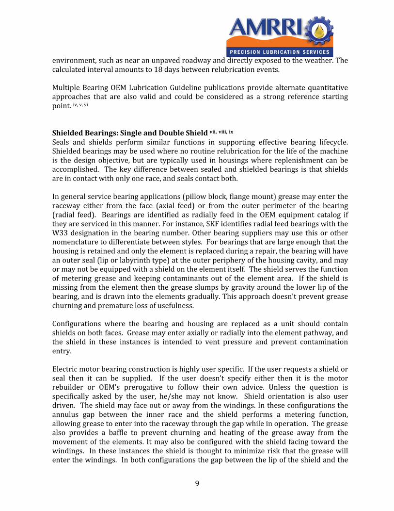
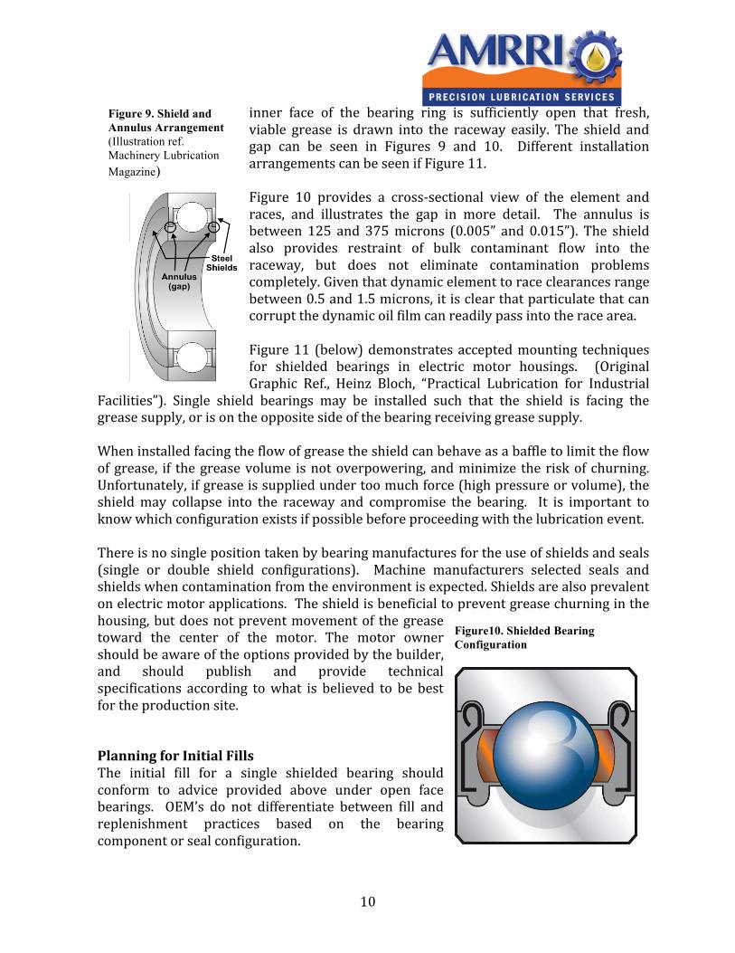
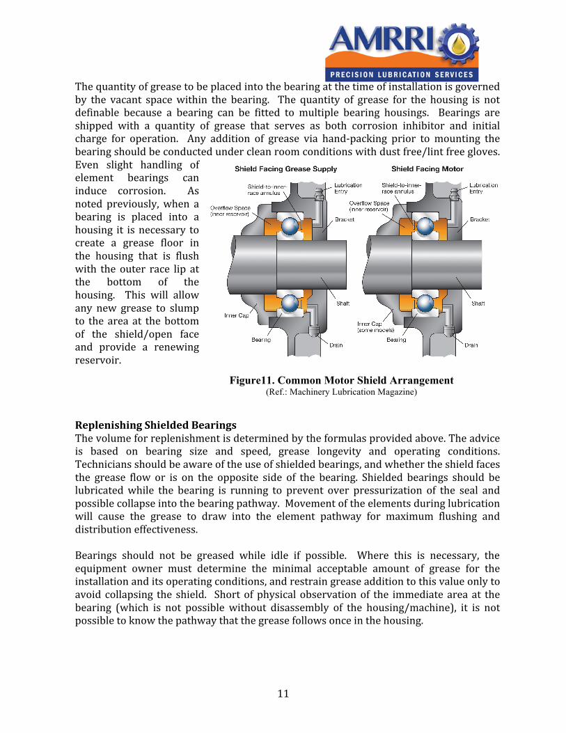
inner face of the bearing ring is sufficiently open that fresh, viable grease is drawn into the raceway easily. The shield and gap can be seen in Figures 9 and 10. Different installation arrangements can be seen if Figure 11. Figure 10 provides a cross-‐sectional view of the element and races, and illustrates the gap in more detail. The annulus is between 125 and 375 microns (0.005” and 0.015”). The shield also provides restraint of bulk contaminant flow into the raceway, but does not eliminate contamination problems completely. Given that dynamic element to race clearances range between 0.5 and 1.5 microns, it is clear that particulate that can corrupt the dynamic oil film can readily pass into the race area. Figure 11 (below) demonstrates accepted mounting techniques for shielded bearings in electric motor housings. (Original Graphic Ref., Heinz Bloch, “Practical Lubrication for Industrial
Facilities”). Single shield bearings may be installed such that the shield is facing the grease supply, or is on the opposite side of the bearing receiving grease supply. When installed facing the flow of grease the shield can behave as a baffle to limit the flow of grease, if the grease volume is not overpowering, and minimize the risk of churning. Unfortunately, if grease is supplied under too much force (high pressure or volume), the shield may collapse into the raceway and compromise the bearing. It is important to know which configuration exists if possible before proceeding with the lubrication event. There is no single position taken by bearing manufactures for the use of shields and seals (single or double shield configurations). Machine manufacturers selected seals and shields when contamination from the environment is expected. Shields are also prevalent on electric motor applications. The shield is beneficial to prevent grease churning in the housing, but does not prevent movement of the grease toward the center of the motor. The motor owner should be aware of the options provided by the builder, and should publish and provide technical specifications according to what is believed to be best for the production site.
Planning for Initial Fills The initial fill for a single shielded bearing should conform to advice provided above under open face bearings. OEM’s do not differentiate between fill and replenishment practices based on the bearing component or seal configuration.
Figure 9. Shield and Annulus Arrangement (Illustration ref. Machinery Lubrication Magazine)
Figure10. Shielded Bearing Configuration
11
The quantity of grease to be placed into the bearing at the time of installation is governed by the vacant space within the bearing. The quantity of grease for the housing is not definable because a bearing can be fitted to multiple bearing housings. Bearings are shipped with a quantity of grease that serves as both corrosion inhibitor and initial charge for operation. Any addition of grease via hand-‐packing prior to mounting the bearing should be conducted under clean room conditions with dust free/lint free gloves. Even slight handling of element bearings can induce corrosion. As noted previously, when a bearing is placed into a housing it is necessary to create a grease floor in the housing that is flush with the outer race lip at the bottom of the housing. This will allow any new grease to slump to the area at the bottom of the shield/open face and provide a renewing reservoir. Replenishing Shielded Bearings The volume for replenishment is determined by the formulas provided above. The advice is based on bearing size and speed, grease longevity and operating conditions. Technicians should be aware of the use of shielded bearings, and whether the shield faces the grease flow or is on the opposite side of the bearing. Shielded bearings should be lubricated while the bearing is running to prevent over pressurization of the seal and possible collapse into the bearing pathway. Movement of the elements during lubrication will cause the grease to draw into the element pathway for maximum flushing and distribution effectiveness. Bearings should not be greased while idle if possible. Where this is necessary, the equipment owner must determine the minimal acceptable amount of grease for the installation and its operating conditions, and restrain grease addition to this value only to avoid collapsing the shield. Short of physical observation of the immediate area at the bearing (which is not possible without disassembly of the housing/machine), it is not possible to know the pathway that the grease follows once in the housing.
Figure11. Common Motor Shield Arrangement
(Ref.: Machinery Lubrication Magazine)
12
Sealed for Life Bearings Within the last few years there has been a marked increase in the dependence on sealed for life bearings for a wide variety of commercial and residential, and even some industrial machines. The concept ‘sealed for life’ reflects the design goal, not the expected operational period. ‘Sealed for life’ is also not a guarantee of operational performance. Sealed for life bearing applications have grown from the traditional deep groove ball bearing to include all shapes, sizes and design parameters. Equipment manufacturers’ primary determining factor for whether to choose a seal (not to be replenished while in use), or a shield, or neither, is driven by machine lifecycle cost and duration requirements. For typical components where sealed bearings are widely or singularly used, the component supplier has concluded that the likelihood of achieving required lifecycle is better if the component is not relubricated. Sealed bearing lifecycles are greatly influenced by the in-‐use grease condition, which is itself influenced by the seal condition (leakage and contaminant exclusion). The significant improvements seen in both grease and seal materials have enabled machine manufactures to design for and achieve longer lifecycles with sealed bearings in progressively more challenging conditions. Favorable conditions for sealed bearings could include:
• Small bearing dimensions • Low shaft rotational speeds • Low shaft circumferential speeds • Low loads • Clean conditions (no moisture, no dust) • Low heat • Short expected lifecycles
As the relative load, surface contact speed, temperature, and contaminant load increase dependence on shielded or open face relubricatable bearings increases. Sealed bearings are not intended to be relubricated during the machines expected lifecycle. However, shielded bearings are configured for and are expected to be replenished on some interval. Elastomeric radial lip seals are designed primarily to retain the lubricant, and are only marginally expected to prevent external contaminant ingression. Seals are capable of containing both liquids and semi-‐solids, are capable of operating in bearing sumps varying from -‐60 to 200oC, can operate with peripheral speeds up to 20 m/s, and support pressures between 20 and 100 kPa (2.9 to 14.5 PSI). Seal radial loading is determined by the types of elastomers used, the contact area of the seal on the race surface, internal pressure from the fluid, and spring tension. As the shaft turns the movement of the shaft causes the seal to flex. This provides a subtle pumping motion that serves to push the fluid toward it’s reservoir area. The fluid creates a film barrier between 0.125 mm and 1.25 mm wide. Lip contact load is a key performance factor. Contact load ranges between 0.05 and 0.12 N/mm (0.3 to 0.7 lb/in) of circumference. As the lip load (spring tension)
13
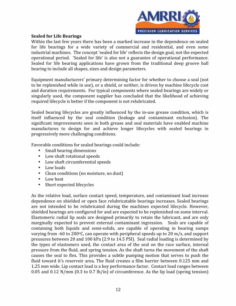
increases the surface temperature rises with respect to shaft speed. Since temperature is a prime cause of seal failure, lip loads should be as low as possible and still maintain a seal. Figure 12 provides a look at the key features of a lip seal. Summary Grease relubrication practices should be handled with care. Precise grease volumes and carefully calculated intervals will help the reliability professional reduced outages, reduce costs, improve machine performance and enjoy a less stressful career. The formulas provided above are either directly or indirectly associated with bearing supplier recommendations. The Lube coach recommendations reflect the principles noted in the provided formulas. These may be programmed into a worksheet without a tremendous amount of effort. The LubeCoach is intended to provide insight without stepping into sophisticated spreadsheet construction. i LubCon GMBH, Bearing lubrication Calculation Worksheet, FAG Bearings, German Society of Tribology, others.
ii FAG Bearings Limited, Roller Bearing Lubrication Guide, Publication Number WL 81 115/4 EC/ED
iii LubCon USA, LubCon GMBH, Bearing lubrication Calculation Worksheet, iv FAG Roller Bearing Lubrication Guideline WL81115E. http://www.fag-‐industrial-‐services.com/gen/download/1/15/40/37/FAG_Rolling_Bearing_Lubrication_WL81115E.pdf.
v Web Reference X.X -‐ Timken Bearing Company http://www.timken.com/industries/torrington/catalog/pdf/general/form640.pdf.
vi Web Reference X.X -‐ SKF Bearing Company. http://mapro.skf.com. vii Snyder, D.R “Sealed-‐for-‐Life Bearings: To Relubricate or Not?” Tribology and Lubrication Technology, December 2004. Pages 33 to 40.
viii Booser, R.E., Tribology Data Handbook, Chapter 14, Dynamic Seals. CRC Press ix Hodowanec, M.M., “Evaluaton of Anti-‐Friction Bearing Lubricatio Methods on Motor Life Cycle Cost”. Siemens Industry and Automation Incorporated. 0-‐7803-‐4785-‐4/98. IEEE.
Figure12. Sealed Bearing Configuration