Embed Size (px)
Citation preview

ltrasonic- low- onverter
15th July 2013 Document-No: DB_GP22-EVA_en V0.2

GP22-EVA-KIT
Publ ished by acam-messelectronic gmbh ©acam-messelectronic gmbh 2013
Disclaimer / Notes The GP22-EVA-KIT is an evaluation system for the integrated circuit TDC-GP22, offered by acam-messelectronic. It is intended for use for engineering development, demonstration or
evaluation. The information provided by this preliminary datasheet is believed to be close to the final
product. However, it is theoretical and no responsibility is assumed by acam for its use, nor for any
infringements of patents or other rights of third parties that may result from its use. The information is subject to change without notice and is provided „as is“ without warranty of
any kind (expressed or implied). Brand and product names in this document are trademarks or service marks of their respective owners.
Support / Contact For a complete listing of Direct Sales, Distributor and Sales Representative contacts, visit
the acam web site at:
http://www.acam.de/sales/distributors/
For technical support you can contact the acam support team in the headquarters in Germany or the Distributor in your country. The contact details of acam in Germany are:
[email protected] or by phone +49-7244-74190.

GP22-EVA-KIT
acam messelectronic gmbh - Friedrich-List-Str.4 - 76297 Stutensee - Germany - www.acam.de 1
Content
1 Introduction .............................................................................................. 1-1
1.1 General .............................................................................................. 1-1
1.2 System Overview .................................................................................. 1-1
1.3 System Components ............................................................................. 1-1
2 Hardware Description ................................................................................. 2-1
2.1 Introduction ........................................................................................ 2-1
2.2 Clock sources ...................................................................................... 2-1
2.3 Power Supply and Current Consumption ................................................... 2-2
2.4 Communication Interface ....................................................................... 2-3
2.5 TDC - Interfaces ................................................................................... 2-4
2.6 Temperature Measurement .................................................................... 2-7
3 Software Description .................................................................................. 3-1
3.1 Installation .......................................................................................... 3-1
3.2 Setup & General Settings Tab ................................................................. 3-6
3.3 Measurement Settings ........................................................................ 3-12
3.4 Standard TDC Measurement ................................................................ 3-17
3.5 Ultrasonic Time-of-Flight Measurement ................................................... 3-19
3.6 Temperature Measurement .................................................................. 3-24
3.7 Graphic ............................................................................................ 3-27
4 Layout and Schematics ............................................................................... 4-1
4.1 Evaluation Board BOM ........................................................................... 4-1
4.2 Layout/Schematics .............................................................................. 4-3
5 Miscellaneous ........................................................................................... 5-1
5.1 Literature Guide ................................................................................... 5-1
5.2 Last Changes ...................................................................................... 5-1

ltrasonic- low- onverter GP22-EVA-KIT
2 acam messelectronic gmbh - Friedrich-List-Str.4 - 76297 Stutensee - Germany - www.acam.de

GP22-EVA-KIT
acam messelectronic gmbh - Friedrich-List-Str.4 - 76297 Stutensee - Germany - www.acam.de 1-1
1 Introduction
1.1 General
The GP22-EVA-KIT evaluation system is designed as a platform for a quick and easy start -
up and evaluation of the TDC-GP22 Time-to-Digital Converter. The EVA-Kit offers user-
friendly configuration and extensive testing of the TDC-GP22.
For a proper use of the evaluation system, we strongly recommended to refer to the
current TDC-GP22 datasheet. You can download this datasheet from
www.acam.de/download-center/time-to-digital-converters.
1.2 System Overview
The GP22-EVA-KIT is a full featured evaluation system for the TDC-GP22 Time to digital
converter. It serves as
System for evaluating ultrasonic time-of-flight measurement applications
Evaluation Kit for TDC-GP22 time interval measurements
PC supported system with USB communication interface
Easy to use evaluation and measurement software
Different power options, selectable by jumpers
Three reference clock sources for alternate clock options
Pt1000 Temperature measurement with on board reference, hardware option for
Pt500 sensors (sensors n.c.)
Internal / external comparator for temperature measurement
Easy connection of external microcontroller boards
Data collection to ASCII text files
Built-in display of measurement results
1.3 System Components
The GP22-EVA-KIT includes the following components:
GP22-EVAL: Evaluation board for TDC-GP22 Time-to-Digital Converter
PICOPROG V2.0: USB-to-SPI communication interface

ltrasonic- low- onverter GP22-EVA-KIT
1-2 acam messelectronic gmbh - Friedrich-List-Str.4 - 76297 Stutensee - Germany - www.acam.de
High density DSUB15 cable: For connecting the evaluation system to the P ICOPROG
V2.0 communication interface
USB cable: For connecting the PICOPROG communication Interface to the local PC
CD-ROM: Contains software, drivers, examples and technical documentation
The GP22-EVAL board is connected to the PC via PicoProg 2.0 device. The PicoProg 2.0
acts as USB to SPI communication interface and provides the power supply of the board.
Figure 1.1 on the following page gives an overview. The 15 pin DSUB high density cable
connects the GP22-EVAL hardware to the PicoProg 2.0. Additionally, a USB cable is
delivered to connect the PicoProg 2.0 with a free USB port of the local PC.
Figure1.1 System Block diagram

GP22-EVA-KIT
acam messelectronic gmbh - Friedrich-List-Str.4 - 76297 Stutensee - Germany - www.acam.de 2-1
2 Hardware Description
2.1 Introduction
The GP22-EVA-KIT, shown in figure 2.1, is an evaluation system for the TDC-GP22 Time-to-
Digital Converter. It offers full access to the TDC-GP22 in order to test and evaluate this
device for your application.
Figure 2.1 GP22-EVA-KIT Hardware
2.2 Clock sources
Besides the 32,768 Hz quartz, the GP22-EVA-KIT includes two high speed clock sources,
a 4 MHz crystal and a 4 MHz ceramic oscillator. The high speed clock source can be
selected by closing the appropriate solder connectors (LJ1 to LJ4). By default LJ3 and
LJ4 are closed so the 4 MHz crystal operates as the system’s high speed clock source.

ltrasonic- low- onverter GP22-EVA-KIT
2-2 acam messelectronic gmbh - Friedrich-List-Str.4 - 76297 Stutensee - Germany - www.acam.de
Solder connector LJ1, LJ2 closed Ceramic oscillator (CER) selected
Solder connector LJ3, LJ4 closed Crystal Oscillator (CRY) selected (Default)
Figure 2.2 High speed clock sources and solder connectors
2.3 Power Supply and Current Consumption
The GP22-EVA-KIT hardware is powered via USB by the PicoProg 2.0 communication
interface. The supply voltage is provided through the 15-pin VGA connector (J1) and can
be adjusted by setting the appropriate jumper. Closing J2, J3 or J4 selects the
corresponding supply voltage. In figure 2.4 the supply voltage is adjusted to 3.0 V.
Figure 2.3: 15-pin VGA connector for power supply
Figure 2.4 Jumpers to select the supply voltage
J2 closed: 2.5 V
J3 closed: 3.0 V (Default)
J4 closed: 3.6 V
In some cases it might be useful to operate the GP22-EVA-KIT without the PicoProg2.0
device, e. g. if the hardware is connected to a microcontroller developers kit. Then the
supply voltage can be fed to Vcc and GND pins of the J19 solder strip. Even in this case

GP22-EVA-KIT
acam messelectronic gmbh - Friedrich-List-Str.4 - 76297 Stutensee - Germany - www.acam.de 2-3
the supply voltage can be adjusted by setting the jumper J2, J3 or J4, as described
above.
GND: Ground Connection
VCC_In: Supply voltage
Figure 2.5 External power supply via J19
Portable or battery driven systems like e. g. heat meters demand for energy efficient
design. To measure the current consumption of the system, Jumper J5 can be left open
and connected to an ampere meter.
Figure 2.6: Measure power consumption
2.4 Communication Interface
2.4.1 VGA Connector
In combination with the PICOPROG 2.0 device the 15-pin VGA-
connector shown below is also used for SPI data communication. The
PICOPROG 2.0 then provides the USB to SPI conversion for data
transfer with the PC based measurement and configuration software.
Figure 2.7: 15-pin VGA connector for power supply and data communication via PICOPROG 2.0

ltrasonic- low- onverter GP22-EVA-KIT
2-4 acam messelectronic gmbh - Friedrich-List-Str.4 - 76297 Stutensee - Germany - www.acam.de
2.4.2 Interfacing an external Microcontroller
Alternative to the VGA connector soldering strip J 19 offers easy access to the SPI data
communication and to signals that are useful for system diagnosis. This is useful when
external hardware like a microcontroller development board should be connected to the
GP22-EVAL board.
Figure 2.8: SPI interface for external hardware
Table 2.1 Signal Description
Int GP22 Interrupt pin
ChipSelect SPI Chipselect line (SSN – Slave Select)
CLK SPI Clock (Clock Serial Interface)
MOSI SPI serial data in (Master Out Slave In)
MISO SPI serial data out (Master In Slave Out)
Reset GP22 Reset line (low active)
GND Ground Connection
LVL Supply voltage for PicoProg 2.0 internal level shifters
Vcc In Optional Power supply, can be used if the system shall be powered without using the PicoProg 2.0 communication interface
2.5 TDC - Interfaces
2.5.1 Fire Pulse Generator Outputs
The fire pulse generator’s outputs (J11 to J14) offer direct connection of the piezo
ceramic transducers for up and down measurement, as it is typical in time -of-flight
applications, like ultrasonic flow- or heat meters.
GP22-EVA-KIT
acam messelectronic gmbh - Friedrich-List-Str.4 - 76297 Stutensee - Germany - www.acam.de 2-5
J11: Fire up
J12, J14: Ground connection
J13: Fire down
Figure 2.9: Fire pulse generator outputs
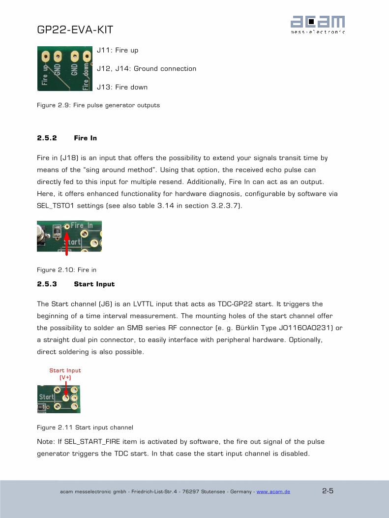
2.5.2 Fire In
Fire in (J18) is an input that offers the possibility to extend your signals transit time by
means of the “sing around method”. Using that option, the received echo pulse can
directly fed to this input for multiple resend. Additionally, Fire In can act as an output.
Here, it offers enhanced functionality for hardware diagnosis, configurable by software via
SEL_TST01 settings (see also table 3.14 in section 3.2.3.7).
Figure 2.10: Fire in
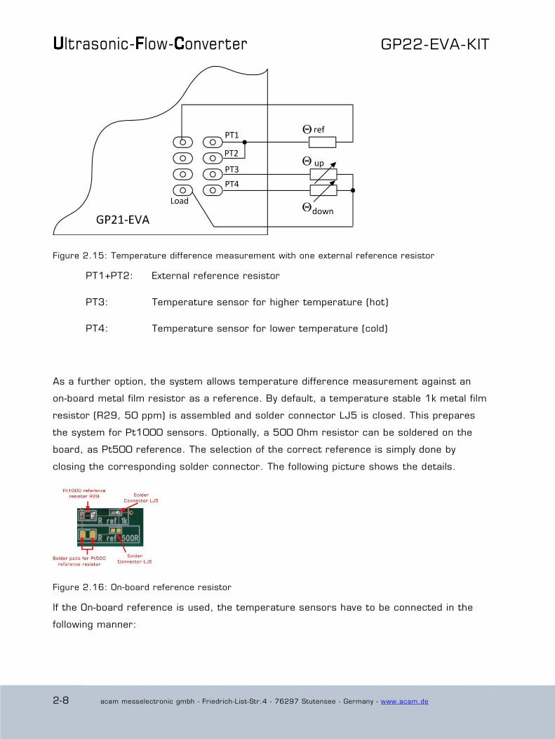
2.5.3 Start Input
The Start channel (J6) is an LVTTL input that acts as TDC-GP22 start. It triggers the
beginning of a time interval measurement. The mounting holes of the start channel offer
the possibility to solder an SMB series RF connector (e. g. Bürklin Type J01160A0231) or
a straight dual pin connector, to easily interface with peripheral hardware. Optionally,
direct soldering is also possible.
Figure 2.11 Start input channel
Note: If SEL_START_FIRE item is activated by software, the fire out signal of the pulse
generator triggers the TDC start. In that case the start input channel is disabled.

ltrasonic- low- onverter GP22-EVA-KIT
2-6 acam messelectronic gmbh - Friedrich-List-Str.4 - 76297 Stutensee - Germany - www.acam.de
2.5.4 Stop Channels
Stop 1 (J7) and Stop 2 (J8) are the Stop inputs for TDC-GP22. They can be interfaced to
analog or digital sources. The selection is done by configuration of the 3-pin jumpers J9
and J10. J9 switches STOP1 as analog or digital input, J10 refers to STOP2. Similar to
the start channel, the mounting holes of the stop channels offer the possibility to solder an
SMB series RF connector (e. g. Bürklin Type J01160A0231) or a straight dual pin
connector, to easily interface with peripheral hardware. Direct soldering is also possible.
Figure 2.12: Stop channels and the corresponding jumpers to switch over between analog -and digital input mode.
Digital LVTTL input enable Analog input enable
Figure 2.13: Jumper settings for analog/digital enable
2.5.5 Start / Stop Enable Pins
J12 provides the high active enable pins for the TDC-GP22 start and stop channels. Each
of the three LVTTL inputs can be used for externally enabling / disabling the
corresponding input channel, e. g. by connecting them to your microcontroller’s general
purpose I/O pins.
Figure 2.13: Enable pins for Start- / Stop channels

GP22-EVA-KIT
acam messelectronic gmbh - Friedrich-List-Str.4 - 76297 Stutensee - Germany - www.acam.de 2-7
EN_Start: By default, high level on EN _Start enables the GP22 start input.
Additionally, it can act as an output. The EN_Start pin then offers
enhanced functionality for hardware diagnosis, configurable by setting
SEL_TST02 (see also table 3.13 in section 3.2.3.7). Easy access to
the EN_Start diagnosis signals is provided by an additional soldering
pad, as shown in figure 2.13.
EN_Stop1: High level on this pin enables stop 1 input
EN_Stop2: High level on this pin enables stop 2 input
2.6 Temperature Measurement
In some applications, like ultrasonic heat meters, temperature difference measurement is
an important feature. Here, the GP22-EVA-KIT offers a fully equipped PICOSTRAIN based
temperature measurement interface for PT500 and PT1000 temperature sensors.
Figure 2.14: Hardware section for temperature measurement
2.6.1 Connecting the temperature sensor
The system offers 4 temperature ports with the possibility of connecting up to 4
temperature sensors. Each of the up to 4 sensors has to be connected between the Load
line and the PT1 to PT4 temperature ports. The load pads are wired in parallel.
ltrasonic- low- onverter GP22-EVA-KIT
2-8 acam messelectronic gmbh - Friedrich-List-Str.4 - 76297 Stutensee - Germany - www.acam.de
Figure 2.15: Temperature difference measurement with one external reference resistor
PT1+PT2: External reference resistor
PT3: Temperature sensor for higher temperature (hot)
PT4: Temperature sensor for lower temperature (cold)
As a further option, the system allows temperature difference measurement against an
on-board metal film resistor as a reference. By default, a temperature stable 1k metal film
resistor (R29, 50 ppm) is assembled and solder connector LJ5 is closed. This prepares
the system for Pt1000 sensors. Optionally, a 500 Ohm resistor can be soldered on the
board, as Pt500 reference. The selection of the correct reference is simply done by
closing the corresponding solder connector. The following picture shows the details.
Figure 2.16: On-board reference resistor
If the On-board reference is used, the temperature sensors have to be connected in the
following manner:

GP22-EVA-KIT
acam messelectronic gmbh - Friedrich-List-Str.4 - 76297 Stutensee - Germany - www.acam.de 2-9
Figure 2.17 Connecting the temperature sensors using the on board reference resistor
PT1+PT2: On board Reference resistor, connected by closing the corresponding
soldering connector LJ6, LJ7 (see figure 2.14)
PT3: Temperature sensor for higher temperature (hot)
PT4: Temperature sensor for lower temperature (cold)
2.6.2 Load Capacitor Selection and Assembly
Depending on your temperature sensor’s base resistance a load capacitor has to be
selected and assembled on the system. As the discharge time should be in the range of
150 µs the following capacitor values are recommended:
Pt500: 220 nF
Pt1000: 100 nF (Default)
To get best results, we recommend C0G type or CFCap series from Tayo Yuden. Up to
three capacitors can be soldered in parallel. By default the system comes with a 100 nF
C0G type, suited for Pt1000 measurements

ltrasonic- low- onverter GP22-EVA-KIT
2-10 acam messelectronic gmbh - Friedrich-List-Str.4 - 76297 Stutensee - Germany - www.acam.de
Figure 2.18: Load capacitor C17 and additional solder pads
2.6.3 Selecting the Comparator
For temperature measurement the external 74AHC14 Schmitt Trigger or the GP22
internal low noise comparator can be used. The selection is done by setting jumper, as
shown in the picture below. Here the external Schmitt Trigger is selected:
Figure 2.19: Jumper to select between internal comparator or external Schmitt Trigger
intern: Selects the GP22 internal comparator
extern: Uses external 74AQHC14 Schmitt Trigger (Default)
Note: For a proper, work the correct setting of „NEG_STOP_TEMP“ parameter in the
“Temperature Measurement” sheet of the software is mandatory. For details, please refer
to table 3.24 in chapter 3.2.6.3 „Temperature port settings“

GP22-EVA-KIT
acam messelectronic gmbh - Friedrich-List-Str.4 - 76297 Stutensee - Germany - www.acam.de 3-1
3 Software Description
The GP22-EVA-KIT evaluation system comes with a comfortable Windows based
configuration and measurement software. This chapter describes the installation and
explains how to access all the functionality of the GP22-EVA-KIT. The following steps are
required:
1. Install the PicoProg 2.0 driver
2. Install the GP22-EVA-KIT software
3. Restart the PC
4. Connect evaluation system to the PC und run the GP22-EVA-KIT software
Install the PicoProg 2.0 driver and the GP22-EVA-KIT software before connecting the
system to the USB port of the PC. This ensures that the system is correctly recognized
when it is connected to the PC. The PicoProg 2.0 driver and the GP22-EVA-KIT software is
compatible to Windows XP (SP3) and Windows 7 (32 and 64-Bit version)
3.1 Installation
3.1.1 PicoProg 2.0 Driver Installation
Insert the GP22-EVA-KIT CD, select the folder Driver\PicoProg v2 Driver Installer Stand-
Alone and run the installer by double clicking setup.exe.
Figure 3.1: Run the Driver Installer
ltrasonic- low- onverter GP22-EVA-KIT
3-2 acam messelectronic gmbh - Friedrich-List-Str.4 - 76297 Stutensee - Germany - www.acam.de
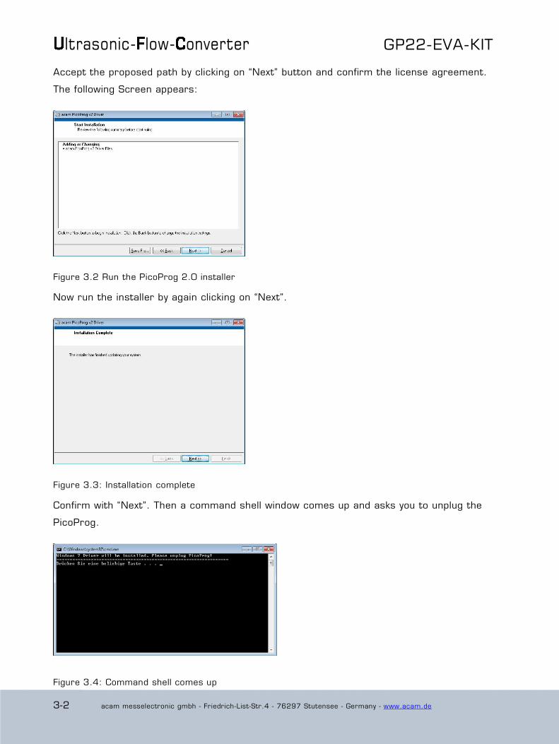
Accept the proposed path by clicking on “Next” button and confirm the license agreement.
The following Screen appears:
Figure 3.2 Run the PicoProg 2.0 installer
Now run the installer by again clicking on “Next”.
Figure 3.3: Installation complete
Confirm with “Next”. Then a command shell window comes up and asks you to unplug the
PicoProg.
Figure 3.4: Command shell comes up

GP22-EVA-KIT
acam messelectronic gmbh - Friedrich-List-Str.4 - 76297 Stutensee - Germany - www.acam.de 3-3
Check that there is no PicoProg device connected to the PC. Then press a key to proceed.
Override the “unsigned driver“ warning.
Figure 3.5 Confirmation before driver installation
Please install the driver anyway. Then the command shell asks you to plug in the PicoProg
V2.0
Figure 3.6 Plug in PicoProg V2.0
Plug in the PicoProg device and press a key.
Figure 3.7 Driver installed

ltrasonic- low- onverter GP22-EVA-KIT
3-4 acam messelectronic gmbh - Friedrich-List-Str.4 - 76297 Stutensee - Germany - www.acam.de
Now the PicoProg v2.0 driver has successfully been installed. To verify the installation you
can open the device manager and locate the driver as shown in figure 3.8.
Figure 3.8 PicoProg 2.0 driver verification
3.1.2 Software Installation
The GP22-EVA-Kit comes with a self-installing measurement and configuration software. It
is provided on the CD and can be installed after the PicoProg installation has been finished
successfully. The following screenshots explain the software installation procedure.
Insert the CD, go to folder Software\GP22_v19 (version 1.9 or newer) Installer and run
the installer by clicking “setup.exe”
Figure 3.9 Run the installer
Now select the installation path. Recommended is the default setting. Then click to “Next”
and confirm the license agreement. After that, a window appears that shows a summary
of the software to be installed.

GP22-EVA-KIT
acam messelectronic gmbh - Friedrich-List-Str.4 - 76297 Stutensee - Germany - www.acam.de 3-5
Figure 3.10: Summary of installation
Go on with “Next”. Then the software installation will be completed.
Figure 3.11: Installation complete
Finally, confirm with “Finish”. Now the system asks for a restart of the PC.
Figure 3.12: Restart your System
Click to “Restart”.

ltrasonic- low- onverter GP22-EVA-KIT
3-6 acam messelectronic gmbh - Friedrich-List-Str.4 - 76297 Stutensee - Germany - www.acam.de
3.2 Setup & General Settings Tab
After starting the software by selecting GP22_v19 (version 1.9 or newer) from the
Windows start menu the following screen appears.
Figure 3.13: Setup & General Settings
The “Setup & General Settings” sheet is divided in different main sections that are
explained in the following chapters.
3.2.1 Setup
The setup section provides basic communication functionality between the GP22-EVA-KIT
software and the GP22-EVA Hardware. This functionality is mainly used to download the
current configuration settings and to prepare the GP22-EVA hardware before starting a
measurement.
In general, the following steps have to be executed before a measurement can be started:
Power on Reset Download Configuration Init Reset

GP22-EVA-KIT
acam messelectronic gmbh - Friedrich-List-Str.4 - 76297 Stutensee - Germany - www.acam.de 3-7
Then the system is configured and ready to start measuring.
Table 3.1 Software functionality in the Setup section
Power On Reset Executes a Power on Reset of the TDC-GP22 hardware by sending SPI opcode 0x50. This resets the complete hardware including the
GP22 configuration registers.
Download config Transmits the current software configuration to the TDC-GP22
configuration registers
Init Reset Prepares the TDC-GP22 for a measurement by sending the init
instruction (0x70). Compared to the „Power on reset“ command the init instruction does not reset the content of the configuration
register.
Verify Interface Offers the possibility to check the USB to SPI communication between
your local PC and the GP22-EVA Kit hardware.
Software Version Displays the version of the currently installed GP22-EVA software
Exit Program Exits the GP22-EVA software
Download Firmware Offers the possibility to manually download the firmware of the
PicoProg V2.0 USP to SPI communication interface. Before using this option please contact acam technical support
USB interface selected
Displays the Product ID and Vendor ID of the USB interface that is selected by the NI-VISA driver.
Vendor ID: 0x194 GP22-EVA-KIT Product ID: 0x100D
3.2.2 Configuration
This section displays the GP22 register configuration and offers the possibility to
save the configurations settings in a *.cfg-file
load a stored configuration from a *.cfg-file
download the current configuration to the GP22-EVA-KIT.
Additionally, the EEPROM section provides the basic instruction set for GP22 EEPROM
access.
ltrasonic- low- onverter GP22-EVA-KIT
3-8 acam messelectronic gmbh - Friedrich-List-Str.4 - 76297 Stutensee - Germany - www.acam.de
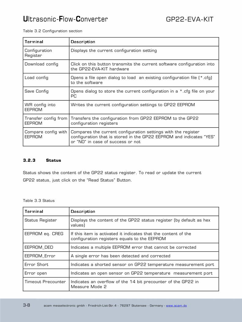
Table 3.2 Configuration section
Configuration Register
Displays the current configuration setting
Download config Click on this button transmits the current software configuration into the GP22-EVA-KIT hardware
Load config Opens a file open dialog to load an existing configuration file (*.cfg) to the software
Save Config Opens dialog to store the current configuration in a *.cfg file on your PC
WR config into EEPROM
Writes the current configuration settings to GP22 EEPROM
Transfer config from EEPROM
Transfers the configuration from GP22 EEPROM to the GP22 configuration registers
Compare config with EEPROM
Compares the current configuration settings with the register configuration that is stored in the GP22 EEPROM and indicates “YES” or “NO” in case of success or not
3.2.3 Status
Status shows the content of the GP22 status register. To read or update the current
GP22 status, just click on the “Read Status” Button.
Table 3.3 Status
Status Register Displays the content of the GP22 status register (by default as hex
values)
EEPROM eq. CREG If this item is activated it indicates that the content of the
configuration registers equals to the EEPROM
EEPROM_DED Indicates a multiple EEPROM error that cannot be corrected
EEPROM_Error A single error has been detected and corrected
Error Short Indicates a shorted sensor on GP22 temperature measurement port
Error open Indicates an open sensor on GP22 temperature measurement port
Timeout Precounter Indicates an overflow of the 14 bit precounter of the GP22 in
Measure Mode 2

GP22-EVA-KIT
acam messelectronic gmbh - Friedrich-List-Str.4 - 76297 Stutensee - Germany - www.acam.de 3-9
Timeout TDC Indicates an overflow of the TDC unit
Read Status Forces the software to read the content of the TDC-GP22 status register and displays the current status as explained above.
3.2.4 Configs to use with Eval System
The GP22EVA-KIT software contains three preconfigured ready–to-use examples. They can
be selected by clicking the requested button in the “Configs to use with Eval System”
section. Then the software automatically loads the corresponding configuration settings.
Sequentially pressing the buttons “Power On Reset Download config Init Reset“
transmits the current setting to the GP22-EVA hardware and the system is ready to start
measuring.
Table 3.4 Preconfigured ready-to-use examples
TDC MRange 2 Basic TDC-GP22 configuration example for a single hit application of the device in measure mode 2. It executes a delay time measurement
in the range between 500ns to 4 ms, triggered by a start event on start input and a stop event on digital stop 1 input.
TDC MRange 1 Basic TDC-GP22 configuration example for a single hit application of the device in measure mode 1. It executes a delay time measurement
in the range between 3.5 ns to 2.5 µs, triggered by a start event on start input and a stop event on digital stop 1 input.
TOF MRange 2 Here, a typical time-of-flight example configuration is provided. The TDC-GP22 operates in measure mode 2 with quad resolution mode, uses its integrated analog section and the fire pulse generator. At
the beginning of a measurement sequence, the pulse generator sends a 1 MHz burst of 10 pulses on Fire out.
On the receiver side, this configuration uses the integrated first -hit detection with 20 mV initial offset. The 3rd, 4th and 7th hit after the
first hit are measured. Also, the pulse width measurement is active. DELVAL1 is set to 5000 (39 µs) to suppress noise from the fire
pulses.
3.2.5 General Settings
The “General Settings” section contains basic configuration parameters that are
application specific. All information for a correct configuration is explained here.
Table 3.5 General Settings

ltrasonic- low- onverter GP22-EVA-KIT
3-10 acam messelectronic gmbh - Friedrich-List-Str.4 - 76297 Stutensee - Germany - www.acam.de
CLKHS frequency /
MHz
Indicates the frequency of the GP22 high speed oscillator. By default,
this value is set to 4 MHz according to the pre-assembled 4 MHz oscillator on the GP22-EVA-KIT hardware. Replacing this oscillator by
another one having a different frequency (2 to 8 MHz) requires the adaption of this value, as it is used to calculate the measurement
results that are displayed in GP22-EVA-KIT software.
Predivider (DIV_CLKHS)
Sets the High Speed Clock Divider. 0 = divided by 1
1 = divided by 2 2 = divided by 4
Start options (START_CLKHS)
Defines the start options of the high speed clock source, especially the settling. Settling means, letting the oscillator stabilize after
switch-on. Osc. Off = Oscillator is switched off
Osc. Continuously On; 1 = Oscillator continuously on 480 µs = settling time 480 µs 1.46 ms = settling time 1.46 ms 2.44 ms = settling time 2.44 ms
5.14 ms = settling time 5.14 ms
Current option 32
kHz osc.
Option for the 32 kHz crystal oscillator. Reduces consumption.
Low current = enables current saving option (recommended setting) High current = disables current saving option, but guarantees
oscillation
EN_STARTNOISE Enables additional noise in start channel, to improve statistics (when
averaging)
DIS_PHASESHIFT Disables the phase-noise generator. Phase noise should be enabled,
though, in those applications where the start pulse is derived from the GP22 high speed clock (e. g. when fire pulse generator is used
for start pulse generation)
EN_FASTINIT Enables fast init operation. Here, the GP22 is automatically prepared
for the next measurement by internally executing the init instruction after an interrupt.
EN_ERR_VAL Activating this item forces the ALU to write 0xFFFFFFFF into the
result register when a timeout occurs
QUAD_RES Increases the resolution by factor 4 to typ. 22 ps (Quad Resolution
Mode, only available in Measure Mode 2)
DOUBLE_RES Increases the resolution by factor 2 to typ. 45 ps (Double Resolution
Mode, available in Measure Mode 1 & 2)
3.2.6 Interrupt Sources
The TDC-GP22 offers several interrupt sources that can be enabled by activating the
corresponding item.

GP22-EVA-KIT
acam messelectronic gmbh - Friedrich-List-Str.4 - 76297 Stutensee - Germany - www.acam.de 3-11
Table 3.6 Interrupt Sources
Timeout TDC 2 An interrupt occurs with TDC overflow ("timeout").
End Hits An interrupt occurs when the expected number of hits has been
received
ALU Interrupt An interrupt occurs if the ALU has finished calculation (has to be
enabled for multi hit applications)
End of EEPROM
action
An interrupt occurs when EEPROM data transfer is completed.
3.2.7 ID
The TDC-GP22 has a 7x32 bit EEPROM that can be used to store the configuration data
together with a device ID or version number. Here, the device ID can be created with
arrow up/down buttons or with direct input to the corresponding text field. Read access
to a stored device ID is provided by click on the “Read ID” button.
Table 3.7 Customer specific ID number
ID0…ID6 Text fields for input of the requested ID number
Read ID Mouse click on this button reads the current ID from the GP22 EEPROM
ID Displays the ID that has been read from the EEPROM after mouse click on “Read ID”

ltrasonic- low- onverter GP22-EVA-KIT
3-12 acam messelectronic gmbh - Friedrich-List-Str.4 - 76297 Stutensee - Germany - www.acam.de
3.3 Measurement Settings
The “Measurement Settings” tab allows access to configure the GP22 time interval
measurement according to the requirements of your application. It is shown in figure 6.2.
Figure 3.14: Measurement Settings
3.3.1 Define HIT Operator in Measure Mode 2
The TDC-GP22 integrates an arithmetic logic unit to calculate the measurement results.
The basic ALU calculation rule is specified by the HIT1 and HIT2 operators. In Measure
Mode 2 it is always HIT2 – HIT1, whereas HIT1 is dedicated to the start event. Because of
that, the incoming stop events have to be assigned to HIT2 operator. In Measure mode 2
the GP22 is capable of measuring up to three hits on the stop input.
Table 3.8: Definition of HIT1 and HIT2 operator in Measure Mode 2
Hit 2 = 1st Stop Ch.
1
The first event on stop channel is assigned to HIT2 operator.
According to the calculation rule HIT2 - HIT1 the ALU now calculates the delay time between the first hit on stop 1 and start. (1st hit on
Stop – Start)
Hit 2 = 2nd Stop Ch. 1
Here the second event on stop channel is assigned to HIT2 operator. According to the calculation rule HIT2 - HIT1 the ALU now
calculates the delay time between the second hit on stop 1 and
GP22-EVA-KIT
acam messelectronic gmbh - Friedrich-List-Str.4 - 76297 Stutensee - Germany - www.acam.de 3-13
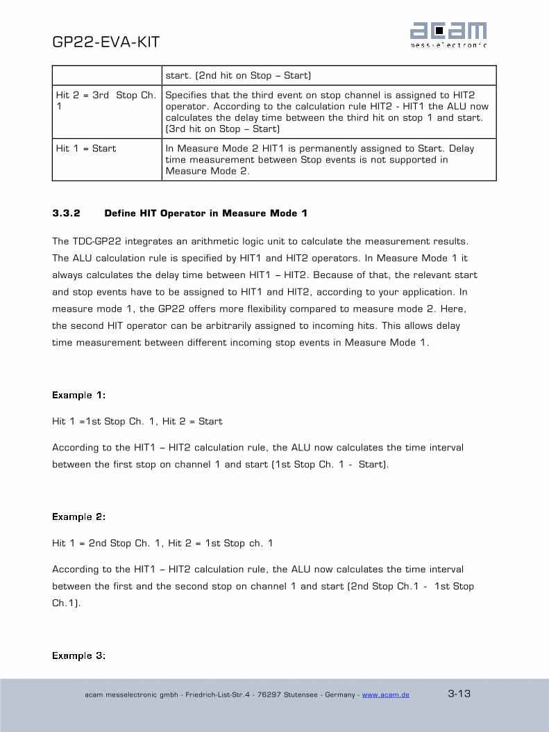
start. (2nd hit on Stop – Start)
Hit 2 = 3rd Stop Ch. 1
Specifies that the third event on stop channel is assigned to HIT2 operator. According to the calculation rule HIT2 - HIT1 the ALU now
calculates the delay time between the third hit on stop 1 and start. (3rd hit on Stop – Start)
Hit 1 = Start In Measure Mode 2 HIT1 is permanently assigned to Start. Delay time measurement between Stop events is not supported in
Measure Mode 2.
3.3.2 Define HIT Operator in Measure Mode 1
The TDC-GP22 integrates an arithmetic logic unit to calculate the measurement results.
The ALU calculation rule is specified by HIT1 and HIT2 operators. In Measure Mode 1 it
always calculates the delay time between HIT1 – HIT2. Because of that, the relevant start
and stop events have to be assigned to HIT1 and HIT2, according to your application. In
measure mode 1, the GP22 offers more flexibility compared to measure mode 2. Here,
the second HIT operator can be arbitrarily assigned to incoming hits. This allows delay
time measurement between different incoming stop events in Measure Mode 1.
Hit 1 =1st Stop Ch. 1, Hit 2 = Start
According to the HIT1 – HIT2 calculation rule, the ALU now calculates the time interval
between the first stop on channel 1 and start (1st Stop Ch. 1 - Start).
Hit 1 = 2nd Stop Ch. 1, Hit 2 = 1st Stop ch. 1
According to the HIT1 – HIT2 calculation rule, the ALU now calculates the time interval
between the first and the second stop on channel 1 and start (2nd Stop Ch.1 - 1st Stop
Ch.1).

ltrasonic- low- onverter GP22-EVA-KIT
3-14 acam messelectronic gmbh - Friedrich-List-Str.4 - 76297 Stutensee - Germany - www.acam.de
Hit 1 = 2nd Stop Ch. 1, Hit 2 = 1st Stop ch. 2
According to the HIT1 – HIT2 calculation rule, the ALU now calculates the time interval
between the second stop on channel 1 and the first one on channel 2 (2nd Stop Ch.1 -
1st Stop Ch.2).
3.3.3 Analog settings
In this section the GP22 internal analog functionality can be configured in this section:
Table 3.9: Analog settings
EN_ANALOG Enables or disables the GP22 analog unit.
EN_ANALOG = STOP1 & STOP 2 digital inputs: Disables the analog section (GP2 compatible). Stop 1 and Stop 2
channels operate as pure digital LVTTL inputs for standard TDC measurements
EN_ANALOG = analog section is used: Enables the GP22 analog unit for time-of-flight measurement
Capacitor charge time TW2
Only relevant if analog section is used. Specifies the charge time of the LoadC capacitor.
TW2 = 90 µs TW2 = 120 µs
TW2 = 150 µs TW2 = 300 µs (Default)
3.3.4 ALU settings
Table 3.10 ALU Settings
Calibration
calculation on
Enables autocalibration mode
Disable Auto-
Calibration
Disables autocalibration mode
Measure Mode 2 Activating this item switches TDC-GP22 to Measure Mode 2
Deactivating this item switches TDC-GP22 to Measure Mode 1
EN_AUTOCALC_MB2 By setting this parameter the chip calculates automatically all three
hits and their sum. The software reads only the content from read register 4, the sum of the three hits.
Select Timeout Measure Mode 2
Specifies a time interval between 64 µs and 1024 µs. If the expected number of hits has not been received within the specified time

GP22-EVA-KIT
acam messelectronic gmbh - Friedrich-List-Str.4 - 76297 Stutensee - Germany - www.acam.de 3-15
(SEL_TIMO_MB2) interval, the GP22 will indicate a timeout.
3.3.5 Expected number of Hits
Specifies the number of incoming events (hits) on the GP22 stop channels.
Table 3.11 Expected number of hits
Expected No, of Hits Stop 1
Specifies the number of incoming stop events on stop channel 1 (STOP1)
Expected No, of Hits Stop 2
Specifies the number of incoming stop events on stop channel 2 (STOP2)
3.3.6 Edge Sensivity
Specifies the edge sensitivity of the start - / Stop channels
Table 3.12 Edge sensitivity configuration of start-/stop channels
Falling Edge START Sets edge sensitivity of start input to falling edge. Rising edge otherwise.
Falling Edge ch. 1 Sets edge sensitivity of stop 1 input to falling edge. Rising edge otherwise.
Both Edges ch. 1 Sets edge sensitivity of stop 1 input to falling and rising edge (e. g, for pulse width measurement)
Falling Edge ch. 2 Sets edge sensitivity of stop 2 input to falling edge. Rising edge otherwise.
Both Edges ch. 2 Sets edge sensitivity of stop 2 input to falling and rising edge (e. g, for pulse with measurement)
3.3.7 Hardware Diagnosis
Additional functionality for hardware diagnosis is provided by the EN_Start – and the Fire_In
pins. This can be configured with parameters SEL_TST02 and SEL_TST01.

ltrasonic- low- onverter GP22-EVA-KIT
3-16 acam messelectronic gmbh - Friedrich-List-Str.4 - 76297 Stutensee - Germany - www.acam.de
Setting SEL_TST02 defines the EN_Start pin as follows:
Table 3.13 SEL_TST02 settings for hardware diagnosis
SEL_TST02 = Start
enable
High active enable pin for GP22 start input (default functionality)
SEL_TST02 = TOF
UP / Down indicator
EN_Start pin acts as TOF up / down indicator. High level indicates
that ToD up measurement is actice
SEL_TST02 = 4 kHz (32 kHz / 8) clock
output
The EN_Start pin outputs a 4 kHz clock signal, e. g. for an external microcontroller.
Setting SEL_TST01 defines the Fire_In pin as follows:
Table 3.14 SEL_TST01 settings for hardware diagnosis
SEL_TST01 = Fire_In
input for sing around
Default functionality. Here, Fire_In can be used as signal input for
“sing around” method
SEL_TST01 = internal stop window
by DELVAL
Enables STOP by DELVAL output
SEL_TST01 =
Comparator out
Output signal from the GP22 internal comparator
SEL_TST01 = 32
kHz out
Fire_In outputs a 32 kHz clock signal for an external microcontroller

GP22-EVA-KIT
acam messelectronic gmbh - Friedrich-List-Str.4 - 76297 Stutensee - Germany - www.acam.de 3-17
3.4 Standard TDC Measurement
If the TDC-GP22 operates as a pure digital Time-to-Digital Converter the “Standard TDC
Measurement Tab” is used to configure the device.
Figure 3.15 Standard TDC Measurement
3.4.1 TDC
Table 3.15: TDC measurement settings
No. samples Avg.
TDC
Specifies the sample size that is used for averaging the measurement
results.
No. samples StDev.
TDC
Specifies the number of results that are used to calculate the
standard deviation
Single Measurement Executes a single TDC measurement
Start cont. Measurement
Executes continuous TDC measurements

ltrasonic- low- onverter GP22-EVA-KIT
3-18 acam messelectronic gmbh - Friedrich-List-Str.4 - 76297 Stutensee - Germany - www.acam.de
3.4.2 Calibration Routines
Table 3.16: Calibration settings
Start_Cal_Res Starts a calibration of high speed oscillator and display the result in the corresponding text field
ANZ_PER_CALRES Defines the number of 32,768 Hz clock periods that are used for calibrating the high speed clock.
Start_Cal_TDC Executes a calibration run of the TDC itself and displays the result in the corresponding text field.
3.4.3 Calculation
Displays the ALU calculation rule. In applications with multiple stop hits activate the radio
button for 2nd, 3rd and 4th result, according to the requested number of hits and enter the
calculation rule in the corresponding text field.
3.4.4 Averaged Results
Displays the measured results. In case of averaging, the mean value of the measured
results is displayed, according to the sample size that is set by the parameter “No.
samples Avg. TDC”
3.4.5 Standard Deviation
Displays the standard deviation of the measured results. The number of results that are
used for calculating the standard deviation is set by the parameter “No. samples StDev .
TDC”

GP22-EVA-KIT
acam messelectronic gmbh - Friedrich-List-Str.4 - 76297 Stutensee - Germany - www.acam.de 3-19
3.5 Ultrasonic Time-of-Flight Measurement
If the analog input unit is used, the TDC-GP22 operates as ultrasonic front-end device that
greatly simplifies development of ultrasonic flow– and heat meters. Then the “Ultrasonic
Time Of Flight measurement” Tab is used for configuration.
Figure 3.16: Ultrasonic Time-of-Flight Measurement
3.5.1 TOF and TOF Restart Sections
Table 3.17: TOF / TOF Restart
Start_TOF Executes a single time-of-flight measurement sequence per mouse
click.
Start_TOF cont. Executes the time-of-flight measurement sequence continuously.
Repetition Time for TOF measurements
in s
Pressing the up / down arrows or inserting a value sets the period for continuous (periodical) time-of-flight measurement runs.
Start_TOF_Restart Runs a time-of-flight measurement sequence twice, in up- and down
direction, as is typical for ultrasonic flow meters.
Start_TOF_Restart A combination of the above. Starts up/down double sequences

ltrasonic- low- onverter GP22-EVA-KIT
3-20 acam messelectronic gmbh - Friedrich-List-Str.4 - 76297 Stutensee - Germany - www.acam.de
cont. periodically.
3.5.2 First Wave Detection
This section configures the automatic first wave detection and the additional pulsewidth
measurement as these are new features in TDC-GP22.
Table 3.18 First Wave Detection
Enable First Wave
Detection
Selects the automatic first wave detection.
First Wave
Negative Edge
Selects first wave detection on the falling edge. Default is off,
triggering on the rising edge.
OFFSRNG2 Adds -20 mV to the variable offset for the first wave detection.
OFFSRNG1 Adds +20 mV to the variable offset for the first wave detection.
Detection
Threshold
Setting the variable offset from -16 mV to +15 mV.
Detection
Threshold in mV
Displays the total offset in mV as it is given by the variable part and the
OFFSRNG settings.
DELREL1,
DELREL2, DELREL3
Defines which hits relative to the first hit shall be measured.
Pulsewidth ratio Displays the ratio of the pulse width for the first wave compared to the pulse width of the first measured hit. Typically in the range of 0.3 to
0.9.
Disable Pulsewidth
measurement
Setting this flag disables the pulse width measurement.
3.5.3 Delay Values
This section configures the time-based masking windows for each of the up to three stop
events by setting of the DELVAL 1 to DELVAL3 parameters. With first wave detection

GP22-EVA-KIT
acam messelectronic gmbh - Friedrich-List-Str.4 - 76297 Stutensee - Germany - www.acam.de 3-21
being active only DELVAL1 is valid and used to suppress initial disturbance e.g. by the fire
pulses.
Table 3.19 Stop Masking
DELVAL1 Specifies the time masking window for the first stop hit on stop 1
channel. Stops will only be accepted after the specified delay time value This window is active also with first wave detection and set default to
5000 (39µs) to suppress noise from the fire pulses.
DELVAL2 Specifies the time masking window for the second stop hit on stop 1 channel. Stops will only be accepted after the specified delay time
value.
DELVAL3 Specifies the time masking window for the third stop hit on stop 1
channel. Stops will only be accepted after the specified delay time value
3.5.4 Fire Pulse
Provides the basic configuration set for the GP22 internal fire pulse generator.
Table 3.20 Basic configuration parameters of the fire pulse generator
FIRE_DOWN Sends the pulse sequence for the time-of-flight measurement from
FIRE_DOWN output. In combination with the Start_TOF_Restart command the time-of-flight measurement sequence begins with a measurement in down direction.
FIRE_UP Sends the pulse sequence for the time-of-flight measurement from FIRE_UP output. In combination with the Start_TOF_Restart command
the time-of-flight measurement sequence is started with a measurement in up direction.
FIRE_BOTH Inverts the output signal on FIRE_DOWN output. This option offers the possibility to increase the signal amplitude on the transmitter side if
the transducer is connected between FIRE_UP and FIRE_DOWN.
SEL_START_FIRE When this item is activated, the fire output is connected chip internally
to the TDC-Start, so the output signal on fire out is used as a start for the time measurement unit. As the external Start input channel is
disabled, any events on that channel will be ignored.
ltrasonic- low- onverter GP22-EVA-KIT
3-22 acam messelectronic gmbh - Friedrich-List-Str.4 - 76297 Stutensee - Germany - www.acam.de
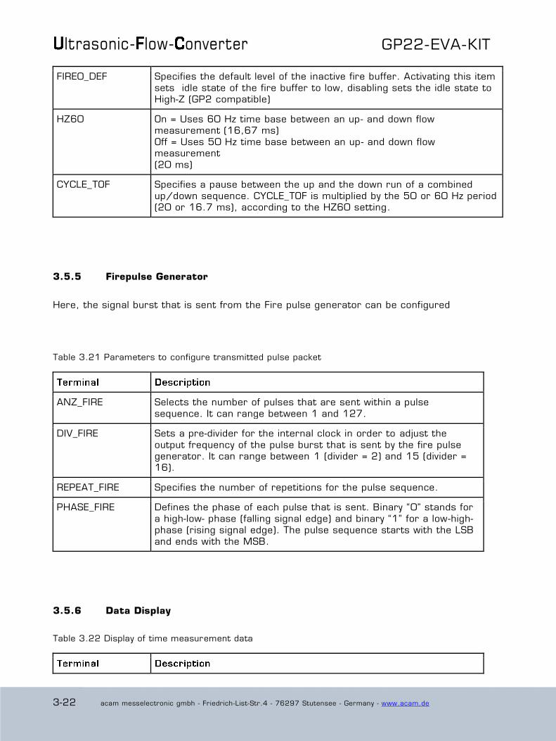
FIRE0_DEF Specifies the default level of the inactive fire buffer. Activating this item
sets idle state of the fire buffer to low, disabling sets the idle state to High-Z (GP2 compatible)
HZ60 On = Uses 60 Hz time base between an up- and down flow measurement (16,67 ms)
Off = Uses 50 Hz time base between an up- and down flow measurement
(20 ms)
CYCLE_TOF Specifies a pause between the up and the down run of a combined
up/down sequence. CYCLE_TOF is multiplied by the 50 or 60 Hz period (20 or 16.7 ms), according to the HZ60 setting.
3.5.5 Firepulse Generator
Here, the signal burst that is sent from the Fire pulse generator can be configured
Table 3.21 Parameters to configure transmitted pulse packet
ANZ_FIRE Selects the number of pulses that are sent within a pulse
sequence. It can range between 1 and 127.
DIV_FIRE Sets a pre-divider for the internal clock in order to adjust the
output frequency of the pulse burst that is sent by the fire pulse generator. It can range between 1 (divider = 2) and 15 (divider = 16).
REPEAT_FIRE Specifies the number of repetitions for the pulse sequence.
PHASE_FIRE Defines the phase of each pulse that is sent. Binary “0” stands for
a high-low- phase (falling signal edge) and binary “1” for a low -high-phase (rising signal edge). The pulse sequence starts with the LSB
and ends with the MSB.
3.5.6 Data Display
Table 3.22 Display of time measurement data

GP22-EVA-KIT
acam messelectronic gmbh - Friedrich-List-Str.4 - 76297 Stutensee - Germany - www.acam.de 3-23
Calculation Displays the ALU calculation rule. For multi hit applications activate
the radio button for 2nd and 3rd result, according to the requested number of hits and enter the calculation rule in the corresponding
text field.
Results Up Displays the Time-of-flight measured in up direction. For multi hit
applications activate the radio button for the 2nd and 3rd, according to the requested number of hits and enter the calculation rule in
the corresponding text field.
Results Down Displays the Time-of-flight measured in down direction. For multi hit
applications activate the radio button for the 2nd and 3rd, according to the requested number of hits and enter the calculation rule in
the corresponding text field.
Difference Down -
Up
Displays the delay time of a complete up-/down time-of-flight
measured in sequence. For multi hit application activate the radio button for the 2nd and the 3rdhit, according to the requested
number of hits and enter the calculation rule in the corresponding text field. The mean value of the measured result is shown in the
last column.
Average Value of
Difference
Displays the averaged delay time of a complete up-/down time-of-
flight measurement sequence. The sample size for averaging is specified in the “No. of samples for Avg. TOF” field. Again, for multi
hit applications activate the radio button for the 2nd and the 3rd hit, according to the requested number of hits and enter the
calculation rule in the corresponding text field. The mean value of result 1 to 3 over the specified sample size is shown in the last
column.
StDev. of Difference
Displays the standard deviation of the time difference Down - Up calculated from as many hits as defined in the “No. of samples for
StDev.” field.
Sum result of
multihit values
Is the sum of the multihit measurement as it is calculated inside
the TDC-GP22 when EN_AUTOCALC_MB2 is set. The software reads only the sum from register 4. It is necessary to set the
divider for the the number of multihits to get the right time data.
Mean value of
Results 1 to 3
Displays the mean of the three multihits as it is calculated by the
evaluation software.
No. of samples for
Avg. TOF
Set the number of samples that is used to calculate the average
value of the time of flight difference.
No. of samples for
StDev.
Set the number of samples that is used to calculate the standard
deviation of the time difference.

ltrasonic- low- onverter GP22-EVA-KIT
3-24 acam messelectronic gmbh - Friedrich-List-Str.4 - 76297 Stutensee - Germany - www.acam.de
3.6 Temperature Measurement
The GP22 integrated temperature measurement unit provides the possibility for
temperature difference measurement. It is configured in the ”Temperature measurement”
sheet.
Figure 3.17: Temperature Measurement
3.6.1 Start measurements
Table 3.23 Start option for temperature difference measurement
Start_Temp_Restart A mouse click on this button runs a temperature difference measurement
cycle twice, for hot and cold, as is typical in ultrasonic heat meters.
Start_Temp Executes a single temperature measurement sequence
Repetition Time for
Temp measurement s
Pressing the up-/down arrows or inserting a value in the text field sets the
period for the periodical temperature measurements.
Start_Temp_cont Here, the Start_Temp command is repeated continuously. The repetition period is specified in “Repetition Time for Temp. measurements in s”

GP22-EVA-KIT
acam messelectronic gmbh - Friedrich-List-Str.4 - 76297 Stutensee - Germany - www.acam.de 3-25
3.6.2 Temperature sensor settings
Specifies additional parameters that refer to the environmental conditions of the
temperature difference measurement and the RTD sensor that is used.
The values that are entered in the corresponding text field are used to calculate the
results that are displayed in this tab.
Table 3.24 Temperature sensor settings
Current
Temperature
Specifies the ambient temperature. The corresponding value is
subtracted from the measured results in order to calculate the absolute temperature difference
Ratio R2/R1 at current
temperature
Specifies the R2/R1 ratio at current ambient temperature
Sensor accuracy in
ppm/K
Specifies the accuracy of the temperature sensor that is used.
3.6.3 Temperature port settings
This section contains the basic parameters to configure the TDC-GP2 temperature
measurement ports.
Table 3.25: Temperature port settings
No. of Temperature Ports
Specifies the number of temperature ports that are used for temperature measurement. If 2 ports are selected, only PT1 and PT2
can be used for temperature measurement.
Cycle Time Defines the time interval to charge and discharge the Load capacitor
(Cload) for temperature measurement.
Fake measurements Specifies the number of fake measurements within a temperature
measurement sequence.
Select reference Selects the reference clock source that triggers the temperature

ltrasonic- low- onverter GP22-EVA-KIT
3-26 acam messelectronic gmbh - Friedrich-List-Str.4 - 76297 Stutensee - Germany - www.acam.de
clock measurement unit.
NEG_STOP_TEMP Specifies if the internal or external comparator is used Ext. 74HC14 is used = selects external comparator
Internal ST is used = selects integrated comparator
CYCLE_TEMP Specifies a pause between the “hot” and the “cold” run of a combined
hot/cold sequence. CYCLE_TEMP is multiplied by the 50 or 60 Hz period (20 or 16.7 ms), according to the HZ60 setting.
Temp_PORT_DIR Temperature ports are measured in opposite order: On = PT1 > PT2 > PT3 > PT4
Off = PT4 > PT3 > PT2 > PT1
3.6.4 Data Display
Table 3.26 Display of temperature measurement data
Temperature 1 to
4
The TDC-GP22 provides raw discharge time data only. Any
calculations are done by the software. This display assumes that the reference is at port PT1.
Mean Temperature in °C
Displays the temperature calculated from the ratio PTx/PT1 on the basis of the platinum temperature curve.
StDev. in mK/Bit Displays the standard deviation in Millikelvin and the resolution in Bit on the basis of sample size defined under „No. samples Avg . for
Temp.“
Ratio RT/Rref Displays the ratios of PTx / PT1
Mean value of RT/Rref
Displays the average calculated with samples size defined under „No. samples Avg. for Temp.“

GP22-EVA-KIT
acam messelectronic gmbh - Friedrich-List-Str.4 - 76297 Stutensee - Germany - www.acam.de 3-27
3.7 Graphic
This page is for the graphical display, showing the measurement results (y) over runtime
(x). The scales can be modified directly by editing the corner values or by using the
magnifying glass tool.
Figure 3.18 Graphical Display of the results
Table 3.27: Controls
1st Result to 4th
Result
Selects the results that are displayed in this tab.
The pulsewidth measurement can be selected under 3rd Result. The sum or average of all 3 results can be displayed under 4th
Result.
TDC Pushing the “Start cont. Measurement” - button in the TDC section
starts a continuous measurement cycle if the TDC-GP22 operates as a pure digital converter without the use of the analog section.
Temperature A mouse click on the “Start_Temp cont” - button in the Temperature section of this tab starts a continuous temperature measurement.
Time-of-flight Pushing” Start_TOF cont.” button executes the time -of-flight measurement sequence continuously.
A mouse click on “Start TOF_Restart cont.” continuously runs a time -of-flight measurement sequence twice, in up- and down direction, as
it is typical for ultrasonic flow meters.

ltrasonic- low- onverter GP22-EVA-KIT
3-28 acam messelectronic gmbh - Friedrich-List-Str.4 - 76297 Stutensee - Germany - www.acam.de
Show and store
every X Result
Offers the possibility to partly show and store the measured results,
e. g. in long term investigation.
Save data to file Stores the measured results in an ASCII file. The max. number of
results is 128,000.
X-/ Y-Zoomfit Enables scaling of the X and Y.-axis for Display of the measured
results

GP22-EVA-KIT
acam messelectronic gmbh - Friedrich-List-Str.4 - 76297 Stutensee - Germany - www.acam.de 4-1
4 Layout and Schematics
4.1 Evaluation Board BOM
Table 4.1 GP22-EVA-KIT BOM
1 U3 74AHC1G14/SOT Inverting Schmitt
3 C3 C6-7 100n C805,100n CHIP-CAPACITOR
4 C8-11 10p C805,10p CHIP-CAPACITOR
1 C2 10u C805,10u CHIP-CAPACITOR
2 C12-13 4n7 C805,4n7 CHIP-CAPACITOR, C0G Type
3 C14-16 n.c. C805,C1206 CHIP-CAPACITOR
1 C4 22u ELKO/49MC_B,22u Tantal Bf. B
1 C5 100u ELKO/49MC_C,100u Tantal Bf. C
1 U2 GP22/QFN32 TDC GP22
1 D2 Green LED/HSMX-PLCC2,Green Surface Mount LED
1 D1 LL4148 DIODE
1 U1 LT1761 100mA Low Noise LDO
6 LJ1-6 Solder Connector
3 J22-24 PAD80/40 PAD 80 / 40 mil
1 X2 4MHz Q/CSTCR 4M00 G53A -R0, 4 MHz
CERAMIC RESONATOR
1 X1 4MHz Q/HC49/4HSMX,4MHz Quartz Oscillator
1 X3 32,768
kHz
Q/KX-327XS,32,768kHz Quartz Crystal
2 R1 R6 0R R805,0R CHIP-RESISTOR
1 R2 100k R805,100k CHIP-RESISTOR
6 R21-22 R24 R33-
35
100k R805,100k CHIP-RESISTOR
1 R23 10M R805,10M CHIP-RESISTOR
2 R3 R12 10R R805,10R CHIP-RESISTOR

ltrasonic- low- onverter GP22-EVA-KIT
4-2 acam messelectronic gmbh - Friedrich-List-Str.4 - 76297 Stutensee - Germany - www.acam.de
1 R11 120k R805,120k CHIP-RESISTOR
1 R8 1M R805,1M CHIP-RESISTOR
1 R29 1k R805,1k CHIP-RESISTOR, 50 ppm
1 R9 20k R805,20k CHIP-RESISTOR
1 R5 22k R805,22k CHIP-RESISTOR
2 R27-28 330R R805,330R CHIP-RESISTOR
1 R10 330k R805,330k CHIP-RESISTOR
1 R7 430k R805,430k CHIP-RESISTOR
1 R4 470k R805,470k CHIP-RESISTOR
2 R25-26 47k R805,47k CHIP-RESISTOR
1 R13 4R7 R805,4R7 CHIP-RESISTOR
1 R30 500R R805,500R CHIP-RESISTOR, 50 ppm
1 R20 560k R805,560k CHIP-RESISTOR
4 J2-5 ST/254_2 2-PIN Header
4 J11-14 ST/254_1_ACAM FASTON TAB 2.8
3 J9-10 J17 ST/254_3_1R 3-PIN HEADER
2 J20-21 ST/254_4_ACAM2
1 J15 ST/254_6_2R_90
1 J19 ST/254_9_1R 9-PIN HEADER 2,54mm 9
polig
1 J1 ST/DSUB15HD_ABG 15 Pole Male DSUB Plug
3 J6-8 ST/SMB_LPM_90
1 J16 TESTPOINT GND
1 J18 TESTPOINT2 Fire In

GP22-EVA-KIT
acam messelectronic gmbh - Friedrich-List-Str.4 - 76297 Stutensee - Germany - www.acam.de 4-3
4.2 Layout/Schematics
Figure 4.1 Component Placement
Figure 4.2 PCB Layer 1

ltrasonic- low- onverter GP22-EVA-KIT
4-4 acam messelectronic gmbh - Friedrich-List-Str.4 - 76297 Stutensee - Germany - www.acam.de
Figure 4.3 PCB Layer 2 (GND)
Figure 4.4 PCB Layer 3 (Power Supply)
GP22-EVA-KIT
acam messelectronic gmbh - Friedrich-List-Str.4 - 76297 Stutensee - Germany - www.acam.de 4-5
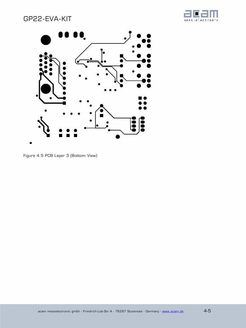
Figure 4.5 PCB Layer 3 (Bottom View)

ltrasonic- low- onverter GP22-EVA-KIT
4-6 acam messelectronic gmbh - Friedrich-List-Str.4 - 76297 Stutensee - Germany - www.acam.de
Figure 4.6 Schematics
GP22-EVA-KIT
acam messelectronic gmbh - Friedrich-List-Str.4 - 76297 Stutensee - Germany - www.acam.de 5-1
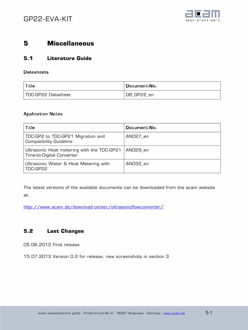
5 Miscellaneous
5.1 Literature Guide
TDC-GP22 Datasheet DB_GP22_en
TDC-GP2 to TDC-GP21 Migration and
Compatibility Guideline
AN027_en
Ultrasonic Heat metering with the TDC-GP21
Time-to-Digital Converter
AN029_en
Ultrasonic Water & Heat Metering with
TDC-GP22
AN032_en
The latest versions of the available documents can be downloaded from the acam website
at:
http://www.acam.de/download-center/ultrasonicflowconverter/
5.2 Last Changes
05.06.2012 First release
15.07.2013 Version 0.2 for release, new screenshots in section 3

acam-messelectronic gmbh
Friedrich-List-Straße 4
76297 Stutensee-Blankenloch
Germany
Phone +49 7244 7419 – 0
Fax +49 7244 7419 – 29
E-Mail [email protected]
www.acam.de