Embed Size (px)
Citation preview

LTM9005
19005p
Typical applicaTion
FeaTures
applicaTions
DescripTion
IF Sampling Receiver Subsystem
The LTM®9005 is an IF Sampling Receiver Subsystem for wireless base stations and communications test equip-ment. Utilizing an integrated System in a Package (SiP) technology, it includes a downconverting mixer, 140MHz SAW filter, two gain stages, a variable attenuator and analog-to-digital converter (ADC). The system is tuned for an Intermediate Frequency (IF) of 140MHz and a signal bandwidth of up to 60MHz; contact Linear Technology regarding customization. The high integration and small package allow for a very compact receiver.
The high signal level downconverting mixer is optimized for high linearity, wide dynamic range IF sampling ap-plications. It includes a high speed differential LO buffer amplifier driving a double-balanced mixer. Broadband, integrated transformers on the RF and LO inputs provide single ended 50Ω interfaces. The RF and LO inputs are internally matched to 50Ω from 1.6GHz to 2.3GHz.
Versions are available with ADCs up to 14-bit resolution and 125Msps. A separate output supply allows the parallel output bus to drive 0.5V to 3.6V logic. A single-ended CLK input controls converter operation. An optional clock duty cycle stabilizer allows high performance at full speed for a wide range of clock duty cycles.
Simplified IF-Sampling Receiver
n Fully Integrated “RF-to-Bits” IF-Sampling Receiver Subsystem
n Wide RF Frequency Range: 400MHz to 3.8GHzn 140MHz Center Frequency Internal SAW Filtern Low Power ADC with Up to 14-Bit Resolution,
125Msps Sample Raten 16dB Cascaded NF, 17.7dBm Two-Tone IIP3n 1.2W Total Power Consumptionn 50Ω Single-Ended RF and LO Portsn Continuous 20dB Attenuation Rangen Internal Bypass Capacitance, No External
Components Requiredn ADC Clock Duty Cycle Stabilizern Digital Output Supply Range: 0.5V to 3.6Vn 15mm × 22mm LGA package
n Base Station Receiversn Remote Radio Headsn Communications Test Equipment
L, LT, LTC, LTM, Linear Technology and the Linear logo are registered trademarks of Linear Technology Corporation. All other trademarks are the property of their respective owners.
IF Frequency Response, 64k Point FFT, RF = 1.95GHz, LO = 1.81GHz
LTM9005
OVDD0.5V to 3.6V
OGND
CLKGNDGAINLO
3.3V
SAWLNA
DAC9005 TA01 IF FREQUENCY (MHz)
80–80
–30
–40
–50
–60
–70
(dB)
–20
–10
100 140120 180160 220200
9005 TA01b
0
Electrical Specifications Subject to Change

LTM9005
29005p
pin conFiguraTionabsoluTe MaxiMuM raTings
Supply Voltage (VCC2, VCC3) ..................... –0.3V to 3.6VSupply Voltage (VCC1, VDD, OVDD) ............. –0.3V to 4.0VDigital Output Ground Voltage (OGND) ........ –0.3V to 1VLO Input Power (380MHz to 4.2GHz) ...................10dBmLO Input DC Voltage ............................. –1V to VCC1 + 1VRF Input Power (400MHz to 3.8GHz) ...................12dBmRF Input DC Voltage ............................................... ±0.1VEN Voltage .....................................–0.3V to VCC1 + 0.3VAMP1SHDN Voltage .......................–0.3V to VCC2 + 0.3VAMP2SHDN Voltage .......................–0.3V to VCC3 + 0.3VGAIN Voltage..................................–0.3V to VCC1 + 0.3VGAIN Current ..........................................................20mADigital Input Voltage..................... –0.3V to (VDD + 0.3V)Digital Output Voltage ................ –0.3V to (OVDD + 0.3V)Operating Ambient Temperature Range
LTM9005C ............................................... 0°C to 70°C LTM9005I ............................................–40°C to 85°C
Storage Temperature Range .................. –45°C to 125°CMaximum Junction Temperature .......................... 125°C
CAUTION: Pins A8, A9, B8, B9, L8, L9, M8 and M9 and the RF and LO inputs are sensitive to electro-static discharge (ESD). It is very important that proper ESD precautions be observed when handling the LTM9005.Avoid ultrasonic exposure, the LTM9005 contains a hermetic cavity filter.
(Notes 1, 2)
LGA PACKAGE204-LEAD (15mm × 22mm × 4.3mm)
TOP VIEW
1
2
3
4
5
6
7
8
10
9
11
12
13
14
15
16
17
LKJHGFEDCB MA
TJMAX = 125°C, θJA = TDB°C/W
LEAD FREE FINISH PART MARKING* PACKAGE DESCRIPTION TEMPERATURE RANGE
LTM9005CV-AA#PBF LTM9005V AA 204-Lead (15mm × 22mm × 4.3mm) LGA 0°C to 70°C
LTM9005IV-AA#PBF LTM9005V AA 204-Lead (15mm × 22mm × 4.3mm) LGA –40°C to 85°C
LTM9005CV-AB#PBF LTM9005V AB 204-Lead (15mm × 22mm × 4.3mm) LGA 0°C to 70°C
LTM9005IV-AB#PBF LTM9005V AB 204-Lead (15mm × 22mm × 4.3mm) LGA –40°C to 85°C
Consult LTC Marketing for parts specified with wider operating temperature ranges. *The temperature grade is identified by a label on the shipping container.For more information on lead free part marking, go to: http://www.linear.com/leadfree/ This product is only offered in trays. For more information go to: http://www.linear.com/packaging/
orDer inForMaTion
(See Pin Functions, Pin Configuration Table)

LTM9005
39005p
elecTrical characTerisTics The l denotes the specifications which apply over the full operating temperature range, otherwise specifications are at TA = 25°C. (Note 3). All specifications apply at maximum gain setting.SYMBOL PARAMETER CONDITIONS MIN TYP MAX UNITS
RF Input Frequency Range No External Matching (Midband) With External Matching (Low Band or High Band)
400
1600 to 2300 3800
MHz MHz
LO Input Frequency Range No External Matching With External Matching
380
1000 to 4200 5000
MHz MHz
RF Input Return Loss ZO = 50Ω, 1600MHz to 2300MHz (No External Matching) >12 dB
LO Input Return Loss ZO = 50Ω, 1000MHz to 5000MHz (No External Matching) >10 dB
RF Input Power for –1dBFS LTM9005-AA RF = 900MHz, LO = 760MHz RF = 1950MHz, LO = 1810MHz LTM9005-AB RF = 900MHz, LO = 760MHz RF = 1950MHz, LO = 1810MHz
TBD TBD
TBD TBD
TBD
–18.8
TBD –17.8
TBD TBD
TBD TBD
dBm dBm
dBm dBm
LO Input Power 1200MHz to 4200MHz 380MHz to 1200MHz
–8 –5
–3 0
2 5
dBm dBm
LO to RF Leakage fLO = 380MHz to 1600MHz fLO = 1600MHz to 4000MHz
<–50 <–45
dBm dBm
RF to LO Isolation fRF = 400MHz to 1700MHz fRF = 1700MHz to 3800MHz
>50 >42
dB dB
2Rf-2LO Output Spurious Product (fRF = fLO + fIF/2)
900MHz: fRF = 830MHz at TBD 1950MHz: fRF = 1880MHz at –19dBm
TBD –71
dBc dBc
3Rf-3LO Output Spurious Product (fRF = fLO + fIF/3)
900MHz: fRF = 807MHz at TBD 1950MHz: fRF = 1857MHz at –19dBm
TBD –96
dBc dBc
FilTer characTerisTics The l denotes the specifications which apply over the full operating temperature range, otherwise specifications are at TA = 25°C.SYMBOL PARAMETER CONDITIONS MIN TYP MAX UNITS
Center Frequency LTM9005-AA LTM9005-AB
140 140
MHz MHz
Lower 1dB Bandedge LTM9005-AA LTM9005-AB
132 130.8
MHz MHz
Upper 1dB Bandedge LTM9005-AA LTM9005-AB
148 149.2
MHz MHz
Lower 3dB Bandedge LTM9005-AA LTM9005-AB
131.5 130
MHz MHz
Upper 3dB Bandedge LTM9005-AA LTM9005-AB
148.5 150
MHz MHz
Lower 35dB Stopband LTM9005-AA LTM9005-AB
129 126.8
MHz MHz
Upper 35dB Stopband LTM9005-AA LTM9005-AB
151 153.2
MHz MHz
Passband Flatness 133.6MHz – 146.4MHz, LTM9005-AA 130.8MHz – 149.2MHz, LTM9005-AB
0.6 0.8
dB dB
Phase Linearity 133.6MHz – 146.4MHz, LTM9005-AA 130.8MHz – 149.2MHz, LTM9005-AB
10 TBD
deg deg
Group Delay 133.6MHz – 146.4MHz, LTM9005-AA 130.8MHz – 149.2MHz, LTM9005-AB
60 115
ns ns
Absolute Delay LTM9005-AA LTM9005-AB
1 1
µs µs

LTM9005
49005p
gain conTrol The l denotes the specifications which apply over the full operating temperature range, otherwise specifications are at TA = 25°C. VCC1 = 3.3V, RF Input = –1dBFS.
SYMBOL PARAMETER CONDITIONS MIN TYP MAX UNITS
Gain Adjustment Range 20 dB
Forward Current Range l 0 10 mA
Response Time 10% to 90% Gain Current Step TBD µs
Input Impedance XX MHz, 0.1 < IGAIN < 10mA 50 Ω
Isolation to Output RF Input = TBD dBm (Note 5) TBD dB
Control Voltage Maximum Gain Gain –20dB
3.3 2.55
V V
DynaMic accuracy The l denotes the specifications which apply over the full operating temperature range, otherwise specifications are at TA = 25°C. (Note 3). All specifications apply at maximum gain setting.
converTer characTerisTics The l denotes the specifications which apply over the full operating temperature range, otherwise specifications are at TA = 25°C. (Note 3)
SYMBOL PARAMETER CONDITIONS MIN TYP MAX UNITS
Resolution (No Missing Codes) LTM9005-Ax l 14 Bits
Integral Linearity Error (Note 4) IF = 140MHz, LTM9005-Ax ±TBD LSB
Differential Linearity Error IF = 140MHz, LTM9005-Ax ±TBD LSB
SYMBOL PARAMETER CONDITIONS MIN TYP MAX UNITS
SNR Signal-to-Noise Ratio at –1dBFS, within the RF Passband
LTM9005-AA RF = 1950MHz, LO = 1810MHz LTM9005-AB RF = 1950MHz, LO = 1810MHz
TBD
TBD
67.2
67
TBD
TBD
dB
dB
SFDR Spurious Free Dynamic Range at –1dBFS 2nd or 3rd Harmonic
LTM9005-AA RF = 1950MHz, LO = 1810MHz LTM9005-AB RF = 1950MHz, LO = 1810MHz
TBD
TBD
75
75
TBD
TBD
dB
dB
SFDR Spurious Free Dynamic Range at –1dBFS 4th or Higher
LTM9005-AA RF = 1950MHz, LO = 1810MHz LTM9005-AB RF = 1950MHz, LO = 1810MHz
TBD
TBD
93.5
93.5
TBD
TBD
dB
dB
S/(N+D) Signal-to-Noise Plus Distortion Ratio at –1dBFS LTM9005-AA RF = 1950MHz, LO = 1810MHz LTM9005-AB RF = 1950MHz, LO = 1810MHz
TBD
TBD
60.5
62
TBD
TBD
dB
dB
IMD3 Intermodulation Distortion at –7dBFS per Tone LTM9005-AA RF = 1950MHz, LO = 1810MHz LTM9005-AB RF = 1950MHz, LO = 1810MHz
TBD
TBD
72.5
72.5
TBD
TBD
dB
dB

LTM9005
59005p
DigiTal inpuTs anD ouTpuTs The l denotes the specifications which apply over the full operating temperature range, otherwise specifications are at TA = 25°C. (Note 3)
SYMBOL PARAMETER CONDITIONS MIN TYP MAX UNITS
Logic Inputs (CLK, OE, ADCSHDN)
VIH High Level Input Voltage VDD = 3V l 2 V
VIL Low Level Input Voltage VDD = 3V l 0.8 V
IIN Input Current VIN = 0V to VDD l –10 10 µA
CIN Input Capacitance (Note 6) 3 pF
Amplifier Shutdown (AMP1SHDN, AMP2SHDN)
VIH High Level Input Voltage VCC2 = VCC3 = 3V l 2.4 V
VIL Low Level Input Voltage VCC2 = VCC3 = 3V l 0.8 V
IIH Input High Current VCC2 = VCC3 = 3V, VIN = 2V 1.3 µA
IIL Input Low Current VCC2 = VCC3 = 3V, VIN = 0.8V 0.1 µA
Mixer Enable (EN)
VIH High Level Input Voltage VCC1 = 3.3V l 2.7 V
VIL Low Level Input Voltage VCC1 = 3.3V l 0.3 V
IIN Input Current VIN = 0V to VCC1 l 53 90 µA
Turn-ON Time 2.8 µs
Turn-OFF Time 2.9 µs
Analog Inputs (Mode, SENSE)
IMODE MODE Input Leakage l –3 3 µA
ISENSE SENSE Input Leakage 0V < SENSE < 1V l –3 3 µA
Logic Outputs
OVDD = 3V
COZ Hi-Z Output Capacitance OE = 3V (Note 6) 3 pF
ISOURCE Output Source Current VOUT = 0V 50 mA
ISINK Output Sink Current VOUT = 3V 50 mA
VOH High Level Output Voltage IO = –10µA IO = –200µA
l
2.7
2.995 2.99
V V
VOL Low Level Output Voltage IO = 10µA IO = 1.6mA
l
0.005 0.09
0.4
V V
OVDD = 2.5V
VOH High Level Output Voltage IO = –200µA 2.49 V
VOL Low Level Output Voltage IO = 1.6mA 0.09 V
OVDD = 1.8V
VOH High Level Output Voltage IO = –200µA 1.79 V
VOL Low Level Output Voltage IO = 1.6mA 0.09 V

LTM9005
69005p
TiMing characTerisTics The l denotes the specifications which apply over the full operating temperature range, otherwise specifications are at TA = 25°C. (Note 3)
Note 1: Stresses beyond those listed under Absolute Maximum Ratings may cause permanent damage to the device. Exposure to any Absolute Maximum Rating condition for extended periods may affect device reliability and lifetime.Note 2: All voltage values are with respect to ground with GND and OGND wired together (unless otherwise noted).Note 3: VCC1 = 3.3V, VCC2 = VCC3 = VDD = 3V, AMP1SHDN = AMP2SHDN = ADCSHDN = 0V, EN = 3.3V, fSAMPLE = 125MHz, RF input power = –10dBm.
SYMBOL PARAMETER CONDITIONS MIN TYP MAX UNITS
fs Sampling Frequency l 1 125 MHz
tL CLK Low Time Duty Cycle Stabilizer Off (Note 6) Duty Cycle Stabilizer On (Note 6)
l
l
3.8 3
4 4
500 500
ns ns
tH CLK High Time Duty Cycle Stabilizer Off (Note 6) Duty Cycle Stabilizer On (Note 6)
l
l
3.8 3
4 4
500 500
ns ns
tAP Sample-and-Hold Aperture Delay Figure 1 (Note 6, Note 7) 0 ns
tJITTER Sample-and-Hold Acquisition Delay Time Jitter (Note 6, Note 7) 0.2 psRMS
tD CLK to DATA delay CL = 5pF (Note 6) l 1.4 2.7 5.4 ns
DATA Access Time After OE↓ CL = 5pF (Note 6) l 4.3 10 ns
BUS Relinquish Time (Note 6) l 3.3 8.5 ns
Pipeline Latency 5 Cycles
Note 4: Integral nonlinearity is defined as the deviation of a code from a “best fit straight line” to the transfer curve. The deviation is measured from the center of the quantization band.Note 5: Noise level superimposed on the GAIN pin at 140MHz required to generate spur above the noise floor.Note 6: Guaranteed by design, not subject to test.Note 7: Analog input measured at L8-L9 pads.
power requireMenTs The l denotes the specifications which apply over the full operating temperature range, otherwise specifications are at TA = 25°C. (Note 3)
SYMBOL PARAMETER CONDITIONS MIN TYP MAX UNITS
VCC1 Mixer Supply Range l 2.9 3.3 3.6 V
VCC2 First Amplifier Supply Range l 2.85 3.3 3.465 V
VCC3 Second Amplifier Supply Range l 2.85 3.3 3.465 V
VDD ADC Analog Supply Voltage l 2.85 3.3 3.465 V
OVDD ADC Digital Output Supply Voltage l 0.5 3.3 3.6 V
ICC1 Mixer Supply Current EN = 3V l 82 92 mA
ICC1(SHDN) Mixer Shutdown Supply Current EN = 0V l 100 µA
ICC2 First Amplifier Supply Current AMP1SHDN = 0V l 90 105 mA
ICC2(SHDN) First Amplifier Shutdown Supply Current AMP1SHDN = 3V l 3 mA
ICC3 Second Amplifier Supply Current AMP2SHDN = 0V l 90 105 mA
ICC3(SHDN) Second Amplifier Shutdown Supply Current AMP2SHDN = 3V l 3 mA
IDD ADC Supply Current ADCSHDN = 0V l 132 156 mA
PD(SHDN) Power Dissipation in Shutdown EN = 0V, AMP1SHDN = AMP2SHDN = ADCSHDN = 3V, OE = 3V, No RF, No LO, No CLK
TBD mW
PD(NAP) ADC Nap Mode Power EN = 0V, AMP1SHDN = AMP2SHDN = ADCSHDN = 3V, OE = 0V, No RF, No LO, No CLK
15 mW
PD(TOTAL) Total Power Dissipation EN = 3V, AMP1SHDN = AMP2SHDN = ADCSHDN = 0V, OE = 0V, fSAMPLE = MAX
1200 mW

LTM9005
79005p
TiMing DiagraM
tAP
N + 1N + 2 N + 4
N + 3 N + 5NANALOG
INPUT
tH
tD
tL
N – 4 N – 3 N – 2 N – 1
CLK
D0-D13, OF
9005 TD01
N – 5 N
Figure 1. Digital Output Bus Timing

LTM9005
89005p
Typical perForMance characTerisTics
LTM9005-AA: 64K Point 2-Tone FFT
LTM9005: 64K Point FFT, Maximum Gain
LTM9005: 64K Point FFT, Minimum Gain
LTM9005: 64K Point FFT, Minimum Gain
FREQUENCY (MHz)0
AMPL
ITUD
E (d
BFS)
0
–20
–40
–60
–80
–100
–10
–30
–50
–70
–90
–110
–12020 4010 30 50
9005 G01
656015 355 25 45 55
fIN = 1949MHz and 1951MHz–7dBFS Per ToneSENSE = VDD
FREQUENCY (MHz)0
AMPL
ITUD
E (d
BFS)
0
–20
–40
–60
–80
–100
–10
–30
–50
–70
–90
–110
–12020 4010 30 50
9005 G02
656015 355 25 45 55
fIN = 900MHz–1dBFSSENSE = VDD
FREQUENCY (MHz)0
AMPL
ITUD
E (d
BFS)
0
–20
–40
–60
–80
–100
–10
–30
–50
–70
–90
–110
–12020 4010 30 50
9005 G03
656015 355 25 45 55
fIN = 900MHz–1dBFSSENSE = VDD
LTM9005: 64K Point FFT, Maximum Gain
FREQUENCY (MHz)0
AMPL
ITUD
E (d
BFS)
0
–20
–40
–60
–80
–100
–10
–30
–50
–70
–90
–110
–12020 4010 30 50
9005 G04
656015 355 25 45 55
fIN = 1950MHz–1dBFSSENSE = VDD
FREQUENCY (MHz)0
AMPL
ITUD
E (d
BFS)
0
–20
–40
–60
–80
–100
–10
–30
–50
–70
–90
–110
–12020 4010 30 50
9005 G05
656015 355 25 45 55
fIN = 1950MHz–1dBFSSENSE = VDD
LTM9005: LO Port ImpedanceLTM9005: LO Port Return Loss vs Frequency
LTM9005: IF Frequency Response
IF FREQUENCY (MHz)40
?? (d
B)
0
–70
–10
–30
–50
–20
–40
–60
–80140 220100 180
9005 G06
240120 20080 16060
FREQUENCY (MHz)
RETU
RN L
OSS
(dB)
9005 G08
0
–30
–25
–20
–15
–10
–5
100 1000 10000
NO MATCHING ELEMENTS1.81GHz MATCH (3.3nH + 1.5pF)840MHz MATCH (1.5pF)

LTM9005
99005p
pin FuncTionsRF (Pin M3): Single-Ended Input for the RF Signal. This pin is internally connected to the primary side of the RF input transformer, which has low DC resistance to ground. If the RF source is not DC blocked, then a series blocking capacitor must be used. The RF input is internally matched from 1.6GHz to 2.3GHz. Operation down to 400MHz or up to 3.8GHz is possible with simple external matching.
LO (Pin M6): Single-Ended Input for the Local Oscillator Signal. This pin is internally connected to the primary side of the LO transformer, which is internally DC blocked. An external blocking capacitor is not required. The LO input is internally matched from 1GHz to 5GHz. Operation down to 380MHz is possible with simple external matching.
GAIN (Pin F1): Cathode of PIN Diode. Sinking current from GAIN attenuates the signal. The forward voltage is approximately 1V and the output impedance is 50Ω.
EN (Pin H1): Mixer Enable Pin. Connecting EN to VCC1 results in normal operation. Connecting EN to GND disables the mixer. The EN pin should not be left floating.
AMP1SHDN (Pin D4), AMP2SHDN (Pin L16): Amplifier En-able Pins. Connecting AMPSHDN to GND results in normal operation. Connecting AMP1SHDN to VCC2 disables the amplifier preceding the SAW filter and connecting AMP-2SHDN to VCC3 disables the amplifier following the SAW filter. It is recommended to tie AMP1SHDN, AMP2SHDN and ADCSHDN together and control with 3V logic.
CLK (Pin A11): ADC Clock Input. The input sample starts on the positive edge.
ADCSHDN (Pin C13): ADC Shutdown Mode Selection Pin. Connecting ADCSHDN to GND and OE to GND results in normal operation with the ADC outputs enabled. Connect-ing ADCSHDN to GND and OE to VDD results in normal operation with the outputs at high impedance. Connecting ADCSHDN to VDD and OE to GND results in nap mode with the outputs at high impedance. Connecting ADCSHDN to VDD and OE to VDD results in sleep mode with the outputs at high impedance.
OE (Pin C12): Output Enable Pin. Refer to ADCSHDN pin function.
Typical perForMance characTerisTics
LTM9005: RF Port ImpedanceLTM9005: RF Port Return Loss vs Frequency
FREQUENCY (MHz)
RETU
RN L
OSS
(dB)
9005 G10
0
–30
–25
–20
–15
–10
–5
100 1000 10000
NO MATCHING ELEMENTS1.95GHz MATCH (5.6nH)700MHz MATCH (4.7pF)900MHz MATCH (2.7pF)

LTM9005
109005p
D0 – D13 (See Table for Pin Locations): Digital Outputs. D13 is the MSB.
OF (Pin G15): Over/Under Flow Output. High when an over or under flow has occurred.
MODE (Pin F15): Output Format and Clock Duty Cycle Stabilizer Selection Pin. Connecting MODE to GND selects offset binary output format and turns the clock duty cycle stabilizer off. 1/3 VDD selects offset binary output format and turns the clock duty cycle stabilizer on. 2/3 VDD selects 2’s complement output format and turns the clock duty cycle stabilizer on. VDD selects 2’s complement output format and turns the clock duty cycle stabilizer off.
SENSE (Pin H12): Reference Programming Pin. Connect-ing SENSE to VDD selects the internal reference and the default input range. Connecting SENSE to 1.5V selects the internal reference and a 3dB lower input range. An external reference greater than 0.5V and less than 1V applied to SENSE selects the external reference. A 1V external refer-ence sets the input range equal to the default input range, a 0.5V external reference sets the input range 3dB lower and an external value between 0.5V and 1V sets the input range proportionally.
A8 (Pin A8): Test Pin Used During Manufacturing Only. Connect directly to B8. Keep this connection free from noise.
A9 (Pin A9): Test Pin Used During Manufacturing Only. Connect directly to B9. Keep this connection free from noise.
B8 (Pin B8): Test Pin Used During Manufacturing Only. Connect directly to A8. Keep this connection free from noise.
B9 (Pin B9): Test Pin Used During Manufacturing Only. Connect directly to A9. Keep this connection free from noise.
L8 (Pin L8): Test Pin Used During Manufacturing Only. Connect directly to M8. Keep this connection free from noise.
L9 (Pin L9): Test Pin Used During Manufacturing Only. Connect directly to M9. Keep this connection free from noise.
M8 (Pin M8): Test Pin Used During Manufacturing Only. Connect directly to L8. Keep this connection free from noise.
M9 (Pin M9): Test Pin Used During Manufacturing Only. Connect directly to L9. Keep this connection free from noise.
OGND (Pins A16, A17, B17, C16 and C17): Output Driver Ground.
OVDD (Pins D16 and D17): Positive Supply for the Output Drivers. This supply is internally bypassed to GND. OVDD can be 0.5V to 3.6V.
VCC1 (Pins K1 and K2): 3.3V Supply Voltage for Mixer. VCC1 is internally bypassed to GND.
VCC2 (Pins B1 and C1): 3.3V Supply Voltage for First Amplifier. VCC2 is internally bypassed to GND. Can operate at 3V if desired.
VCC3 (Pins M14 and M15): 3.3V Supply Voltage for Second Amplifier. VCC3 is internally bypassed to GND. Can operate at 3V if desired.
VDD (Pins A13 and B13): 3.3V Supply Voltage for ADC. VDD is internally bypassed to GND. Can operate at 3V if desired.
GND (See Table for Pin Locations): Module Ground.
pin FuncTions

LTM9005
119005p
Pin ConfigurationA B C D E F G H J K L M
1 GND VCC2 VCC2 GND GND GAIN GND EN GND VCC1 GND GND
2 GND GND GND GND GND GND GND GND GND VCC1 GND GND
3 GND GND GND GND GND GND GND GND GND GND GND RF
4 GND GND GND AMP1 SHDN GND GND GND GND GND GND GND GND
5 GND GND GND GND GND GND GND GND GND GND GND GND
6 GND GND GND GND GND GND GND GND GND GND GND LO
7 GND GND GND GND GND GND GND GND GND GND GND GND
8 A8 B8 GND GND GND GND GND GND GND GND L8 M8
9 A9 B9 GND GND GND GND GND GND GND GND L9 M9
10 GND GND GND GND GND GND GND GND GND GND GND GND
11 CLK GND GND GND GND GND GND GND GND GND GND GND
12 GND GND OE GND GND GND GND SENSE GND GND GND GND
13 VDD VDD ADC SHDN GND GND GND GND GND GND GND GND GND
14 D0 D2 GND GND GND GND GND GND GND GND GND VCC3
15 D1 D3 GND GND D5 MODE OF GND GND GND GND VCC3
16 OGND D4 OGND OVDD D6 D9 D11 D13 GND GND AMP2 SHDN GND
17 OGND OGND OGND OVDD D7 D8 D10 D12 GND GND GND GND
Top View of LGA Package (Looking Through Component)
block DiagraM
Simplified Block Diagram
VCC2 VDD
OVDD
D13…D0
OF
CLK MODESENSELO
VCC1
SAW
9005 BD01
50Ω
GAIN AMP1 SHDN
1STAMPLIFIER
VCC3
BPF
OE
2NDAMPLIFIER
14-BITADC
OUTPUTDRIVERS
1.5VREFERENCE
RANGESELECT
50Ω0.1µF
ADC SHDN
REFERENCEBUFFER
AMP2 SHDN
OGND
EN
RF
pin FuncTions

LTM9005
129005p
operaTionDESCRIPTION
The LTM9005 is an integrated System in a Package (SiP) that includes a high-speed 14-bit A/D converter, two low-distortion fixed-gain amplifiers, a SAW filter, a continuously variable attenuator and an active mixer. The LTM9005 is designed for very compact IF sampling applications with RF input frequencies up to 3.8GHz. Typical applications include wireless base stations, remote radio heads and communications test instrumentation.
All of the supply bypassing and passive filtering has been included inside the LTM9005 making the total solution size extremely small. Furthermore, the tight coupling makes the performance more consistent and less dependent on board layout. Great care has been taken to protect sensi-tive signals from noise within the µModule package and isolate the RF section from the digital section.
The overall gain is optimized for the dynamic range of the ADC relative to the RF input level allowed by the mixer. The equivalent cascaded noise figure is 16dB. The RF input level for –1dBFs is typically –19dBm.
The following sections describe the operation of each functional element. The SiP technology allows the LTM9005 to be customized and this is described in the Semi-Custom Options section. The outline of the remaining sections follows the basic functional elements as shown in Figure 2.
• RFInputPort
• LOInputPort
• ADCClockInputPort
• GAINControlInput
• SENSEandReferenceInput
• DigitalOutputs
• ShutdownControl
• PowerSupplies
• Layout
SEMI-CUSTOM OPTIONS
The µModule construction affords a new level of flexibility in application-specific standard products. Standard mixed-signal, IF and RF components can be integrated regardless of their process technology and matched with passive components to a particular application. The LTM9005-AA, as the first example, is configured with a 14-bit ADC sampling at rates up to 125Msps. The total system gain is 22dB of which 20dB is variable. The IF is fixed by the SAW filter at 140MHz with 16MHz bandwidth. The RF range is matched for 1.6GHz to 2.3GHz with external matching required to achieve 400MHz to 3.8GHz.
However, other options are possible through Linear Technology’s semi-custom development program. Linear Technology has in place a program to deliver other speed, resolution, RF/IF range, gain and filter configurations for nearly any specified application. ADC resolution and speed options range from 14-bits and 125Msps to 10-bits and 10Msps. The IF can be set from 70MHz to about 270MHz with bandwidths from a few MHz to about 60MHz. These semi-custom designs are based on existing ADCs, am-plifiers, filters and mixers with appropriately modified matching networks. The final subsystem is then tested to the exact parameters defined for the application. The final result is a fully integrated, accurately tested and optimized solution in the same package. For more details on the semi-custom receiver subsystem program, contact Linear Technology.
Figure 2. Basic Functional Elements
LTM9005
VCC2 VDD
OVDD
OGND
ADC CLK
ADC
GAIN CONTROLGND
LO
MIXER
ATTENUATOR
RF
VCC1 VCC3
SAW BPF1STAMPLIFIER
2NDAMPLIFIER
9005 F02
The Applications section describes the design consider-ations and recommendations for interfacing to the key ports and functions as well as board layout in the follow-ing order:

LTM9005
139005p
operaTionDown-Converting Mixer
The mixer stage consists of a high linearity double-bal-anced mixer, RF buffer amplifier, high speed limiting LO buffer amplifier and bias/enable circuits. The RF and LO inputs are both single ended. Low side or high side LO injection can be used.
The RF input consists of an integrated transformer and a high linearity differential amplifier. The primary terminals of the transformer are connected to the RF input and ground. The secondary side of the transformer is internally con-nected to the amplifier’s differential inputs.
The LO input consists of an integrated transformer and high speed limiting differential amplifiers. The amplifiers are designed to precisely drive the mixer for the highest linearity and the lowest noise figure.
Attenuator
A dual PIN diode with common-cathode connection is used for continuously variable attenuation. The anodes are connected to the outputs of the mixer and pulled up to VCC1 through 100nH inductors. The cathode includes a series 50Ω resistor to GAIN. See the GAIN Control Input section for applications information.
First and Second Amplifiers
The amplifiers used in the LTM9005 are low noise and low distortion fully differential ADC drivers. The ampli-fiers are fully differential amplifiers with on chip feedback resistors.
SAW Filter
A high selectivity, surface acoustic wave (SAW) filter is integrated in the LTM9005.
(Applications to provide additional text)
Band-Pass Filter
An L-C bandpass filter follows the second amplifier to prevent aliasing and to minimize the noise contribution of the second amplifier.
(Applications to provide additional text)
Analog to Digital Converter
The analog-to-digital converter (ADC) is a CMOS pipelined multistep converter. The converter has six pipelined ADC stages; a sampled analog input will result in a digitized value five cycles later (see Digital Output Bus Timing). The CLK input is single-ended. The ADC has two phases of operation, determined by the state of the CLK input pin.
Each pipelined stage contains an ADC, a reconstruction DAC and an interstage residue amplifier. In operation, the ADC quantizes the input to the stage and the quantized value is subtracted from the input by the DAC to produce a residue. The residue is amplified and output by the residue amplifier. Successive stages operate out of phase so that when the odd stages are outputting their residue, the even stages are acquiring that residue and visa versa.
When CLK is low, the analog input is sampled differen-tially directly onto the input sample-and-hold capacitors. At the instant that CLK transitions from low to high, the sampled input is held. While CLK is high, the held input voltage is buffered by the S/H amplifier which drives the first pipelined ADC stage. The first stage acquires the output of the S/H during this high phase of CLK. When CLK goes back low, the first stage produces its residue which is acquired by the second stage. At the same time, the input S/H goes back to acquiring the analog input. When CLK goes back high, the second stage produces its residue which is acquired by the third stage. An identical process is repeated for the third, fourth and fifth stages, resulting in a fifth stage residue that is sent to the sixth stage ADC for final evaluation.
Each ADC stage following the first has additional range to accommodate flash and amplifier offset errors. Results from all of the ADC stages are digitally synchronized such that the results can be properly combined in the correction logic before being sent to the output buffer.

LTM9005
149005p
applicaTions inForMaTionRF Input Port
The RF input is shown in Figure 3 and is internally matched from 1.6GHz to 2.3GHz, requiring no external components over this frequency range. The input return loss, shown in Figure 4, is typically 12dB at the band edges. The input match at the lower band edge can be optimized with a series 3.9pF capacitor at Pin M3, which improves the 1.6GHz return loss to greater than 25dB. Likewise, the 2.3GHz match can be improved to greater than 25dB with a series 1.5nH inductor. A series 2.7nH/2.2pF network will simultaneously optimize the lower and upper band edges and expand the RF input bandwidth to 1.2GHz to 2.5GHz. Measured RF input return losses for these three cases are also plotted in Figure 4.
Figure 3. RF Input Schematic
Figure 5. RF Input Return Loss with and Without Matching
Alternatively, the input match can be shifted as low as 400MHz or up to 3800MHz by adding a shunt capacitor (C5) to the RF input. A 450MHz input match is realizedwith C5 = 12pF, located 6.5mm away from Pin M3 on a 50Ω input transmission line. A 900MHz input match requires C5 = 3.9pF, located at 1.7mm. A 3.6GHz input match is realized with C5 = 1pF, located at 2.9mm. This series transmission line/shunt capacitor matching topology allows the LTM9005 to be used for multiple frequency standards without circuit board layout modifications. The series transmission line can also be replaced with a series chip inductor for a more compact layout.
Input return losses for the 450MHz, 900MHz, 2.6GHz and 3.6GHz applications are plotted in Figure 5. The input return loss with no external matching is repeated in Figure 5 for comparison. The 2.6GHz RF input match uses the high-pass matching network shown in Figure 3 with C5 = 3.9pF and L5 = 3.6nH. The high-pass input matching network is also used to create a wideband or dual-band input match. For example, with C5 = 3.3pF and L5 = 10nH, the RF input is matched from 800MHz to 2.2GHz, with optimum matching in the 800MHz to 1.1GHz and 1.6GHz to 2.2GHz bands, simultaneously.
Figure 4. Series Reactance Matching
RFINZO = 50Ω
L = L (mm)
C5
RF
9005 F03
RFIN C5
L5
LOW-PASS MATCHFOR 450MHz, 900MHz
and 3.6GHz RF
HIGH-PASS MATCHFOR 2.6GHz RFAND WIDEBAND RF
TOMIXER
3
FREQUENCY (GHz)0.2
–30
RF P
ORT
RETU
RN L
OSS
(dB)
–25
–20
–15
–10
1.2 2.2 3.2 4.2
9005 F04
–5
0
0.7 1.7 2.7 3.7
SERIES 2.7nHAND 2.2pF
NO EXT MATCH
SERIES 1.5nHSERIES 3.9pF
FREQUENCY (GHz)0.2
–30
RF P
ORT
RETU
RN L
OSS
(dB)
–25
–20
–15
–10
1.2 2.2 3.2 4.2
9005 F05
–5
0
0.7 1.7 2.7 3.7
450MHzL = 6.5mmC5 = 12pF
2.6GHzSERIES 3.9pFSHUNT 3.6nH
3.6GHzL = 2.9mmC5 = 1pF
900MHzL = 1.7mmC5 = 3.9pF
NO EXTMATCH

LTM9005
159005p
applicaTions inForMaTionRF input impedance and S11 versus frequency (with no external matching) are listed in Table 1 and referenced to Pin M3. The S11 data can be used with a microwave circuit simulator to design custom matching networks and simulate board-level interfacing to the RF input filter.
Table 1 RF Input Impedance vs FrequencyFREQUENCY
(MHz)INPUT
IMPEDANCES11
MAG ANGLE
50 4.6 + j2.3 0.832 174.7
300 9.1 + j11.2 0.706 153.8
450 12.0 + j14.5 0.639 145.8
600 14.7 + j17.4 0.588 138.7
900 20.5 + j23.3 0.506 123.4
1300 34.4 + j30.3 0.380 97.5
1700 59.6 + j23.8 0.299 55.8
1950 69.2 + j2.8 0.163 6.9
2200 59.2 – j18.1 0.184 –53.5
2450 41.5 – j24.5 0.274 –94.2
2700 28.3 – j21.3 0.374 –120.3
3000 19.0 – j13.5 0.481 –145.5
3300 13.9 – j5.1 0.568 –167.3
3600 10.8 + j3.4 0.645 171.9
3900 9.4 + j12.3 0.700 151.4
RF Input Overload
In the event of an overload condition at the RF in-put, (Applications to provide additional text following characterization).
LO Input Port
The LO input, shown in Figure 6, is internally matched from 1GHz to 5GHz. The input match can be shifted down, as low as 750MHz, with a single shunt capacitor (C4) on Pin M6. One example is plotted in Figure 7 where C4 = 2.7pF produces a 50MHz to 1GHz match.
Figure 6. LO Input Schematic
Figure 7. LO Input Return Loss
LO input matching below 750MHz requires the series inductor (L4)/shunt capacitor (C4) network shown in Figure 6. Two examples are plotted in Figure 7 where L4 = 2.7nH/C4 = 3.9pF produces a 650MHz to 830MHz match and L4 = 10nH/C4 = 8.2pF produces a 460MHz to 560MHz match.
The optimum LO drive is –3dBm for LO frequencies above 1.2GHz, although the amplifiers are designed to accom-modate several dB of LO input power variation without significant mixer performance variation. Below 1.2GHz, 0dBm LO drive is recommended for optimum noise figure, although –3dBm will still deliver good conversion gain and linearity.
LOIN
C4
L4 LO
VCC1
LIMITER
VREF
9005 F06
EXTERNALMATCHING
FOR LO < 1GHzTOMIXER
15
REGULATOR
LO FREQUENCY (GHz)
0.3
L4 = 10nHC4 = 8.2pF
L4 = 2.7nHC4 = 3.9pF
L4 = 0C4 = 2.7pF
–30
LO P
ORT
RETU
RN L
OSS
(dB)
–10
0
1 5
9005 F07
–20
NO EXTMATCH

LTM9005
169005p
applicaTions inForMaTionCustom matching networks can be designed using the port impedance data listed in Table 2. This data is referenced to the LO pin with no external matching.
Table 2 LO Input Impedance vs FrequencyFREQUENCY
(MHz)INPUT
IMPEDANCES11
MAG ANGLE
50 10.0 – j326 0.991 –17.4
300 80.5 – j41.9 0.820 –99.2
500 11.8 – j10.1 0.632 –155.9
700 18.8 + j10.9 0.474 151.8
900 35.0 + j27.4 0.350 100.8
1200 72.9 + j19.3 0.241 31.3
1500 70.0 – j12.6 0.196 –26.1
1800 55.0 – j17.0 0.167 –64.3
2200 47.8 – j9.7 0.102 –97.2
2600 53.6 – j1.9 0.039 –26.8
3000 66.7 + j0.7 0.143 2.1
3500 82.1 – j13.9 0.263 –17.4
4000 69.0 – j30.1 0.290 –43.5
4500 43.7 – j13.2 0.154 –107.5
5000 36.4 + j19.8 0.271 111.6
LO Input Overload
Text to come.
Reference Operation
The LTM9005 includes an internal voltage reference that is internally bypassed. An external reference can be used or the internal reference can be configured for two pin selectable input ranges. Tying the SENSE pin to VDD selects the default range; tying the SENSE pin to 1.5V selects a 3dB lower range.
Other voltage ranges in-between the pin selectable ranges can be programmed. An external reference can be used by applying its output directly or through a resistive divider
Figure 8. Sinusoidal Single-Ended CLK Driver
to SENSE. It is not recommended to drive the SENSE pin with a logic device. The SENSE pin should be tied to the appropriate level as close to the converter as possible. If the SENSE pin is driven externally, note that this pin is filtered internally with a 50Ω series resistor and a 0.1µF capacitor to ground.
ADC Clock Input
The CLK input can be driven directly with a CMOS or TTL level signal. A sinusoidal clock can also be used along with a low-jitter squaring circuit before the CLK pin (Figure 8).
CLK
50Ω
0.1µF
0.1µF
4.7µF
1k
1k
FERRITE BEAD
CLEANSUPPLY
SINUSOIDALCLOCKINPUT
9005 F08
NC7SVU04
LTM9005
The noise performance of the ADC can depend on the clock signal quality as much as on the analog input. Any noise present on the CLK signal will result in additional aperture jitter that will be RMS summed with the inherent ADC aperture jitter.
In applications where jitter is critical, use as large an amplitude as possible. Also, if the ADC is clocked with a sinusoidal signal, filter the CLK signal to reduce wideband noise and distortion products generated by the source.
Figure 9 and Figure 10 show alternatives for converting a differential clock to the single-ended CLK input. The use of a transformer provides no incremental contribution

LTM9005
179005p
applicaTions inForMaTion
to phase noise. The LVDS or PECL to CMOS translators provide little degradation below 70MHz, but at 140MHz will degrade the SNR compared to the transformer solution. The nature of the received signals also has a large bearing on how much SNR degradation will be experienced. For high crest factor signals such as WCDMA or OFDM, the use of these translators will have a lesser impact.
The transformer in the example may be terminated with the appropriate termination for the signaling in use. The use of a transformer with a 1:4 impedance ratio may be desirable in cases where lower voltage differential signals are considered. The center tap may be bypassed to ground through a capacitor close to the ADC if the differential signals originate on a different plane. The use of a capacitor at the input may result in peaking, and
depending on transmission line length may require a 10Ω to 20Ω series resistor to act as both a lowpass filter for high frequency noise that may be induced into the clock line by neighboring digital signals, as well as a damping mechanism for reflections.
Maximum and Minimum Conversion Rates
The maximum conversion rate for the ADC is 125Msps. The lower limit of the sample rate is determined by the droop of the sample-and-hold circuits. The pipelined ar-chitecture of this ADC relies on storing analog signals on small valued capacitors. Junction leakage will discharge the capacitors. The specified minimum operating frequency for the LTM9005 is 1Msps.
Clock Duty Cycle Stabilizer
An optional clock duty cycle stabilizer circuit ensures high performance even if the input clock has a non 50% duty cycle. Using the clock duty cycle stabilizer is recommended for most applications. To use the clock duty cycle stabilizer, the MODE pin should be connected to 1/3VDD or 2/3VDD using external resistors.
This circuit uses the rising edge of the CLK pin to sample the analog input. The falling edge of CLK is ignored and the internal falling edge is generated by a phase-locked loop. The input clock duty cycle can vary from 40% to 60% and the clock duty cycle stabilizer will maintain a constant 50% internal duty cycle. If the clock is turned off for a long period of time, the duty cycle stabilizer circuit will require a hundred clock cycles for the PLL to lock onto the input clock.
For applications where the sample rate needs to be changed quickly, the clock duty cycle stabilizer can be disabled. If the duty cycle stabilizer is disabled, care should be taken to make the sampling clock have a 50% (±5%) duty cycle.
GAIN Control Input
The total receiver gain is continuously adjustable using a PIN diode. Maximum gain is set by forcing GAIN to VCC1.
Figure 9. CLK Driver Using an LVDS or PECL to CMOS Converter
Figure 10. LVDS or PECL CLK Drive Using a Transformer
CLK100Ω
0.1µF
4.7µF
FERRITE BEAD
CLEANSUPPLY
IF LVDS USE FIN1002 OR FIN1018. FOR PECL, USE AZ1000ELT21 OR SIMILAR
9005 F09
LTM9005
CLK
5pF-30pF
ETC1-1T
0.1µF
VCM
FERRITE BEAD
DIFFERENTIALCLOCKINPUT
9005 F10
LTM9005

LTM9005
189005p
The DAC used to control GAIN will contribute a non-neg-ligible amount of voltage noise. (Text to come—discuss further and provide noise analysis.)
In some applications it may be sufficient to permanently set the gain to a fixed level. This simplifies the circuitry as a fixed resistor to ground can be implemented.
DIGITAL OUTPUTS
Table 3 shows the relationship between the analog input voltage, the digital data bits, and the overflow bit.
Table 3. Output Codes vs Input Voltage, LTM9005-AAINPUT
(SENSE = VDD)OF D13 – D0
(OFFSET BINARY)D13 – D0
(2’S COMPLEMENT)
Overvoltage Maximum
1 0 0
11 1111 1111 1111 11 1111 1111 1111 11 1111 1111 1110
01 1111 1111 1111 01 1111 1111 1111 01 1111 1111 1110
0 0 0 0
10 0000 0000 0001 10 0000 0000 0000 01 1111 1111 1111 01 1111 1111 1110
00 0000 0000 0001 00 0000 0000 0000 11 1111 1111 1111 11 1111 1111 1110
Minimum Undervoltage
0 0 1
00 0000 0000 0001 00 0000 0000 0000 00 0000 0000 0000
10 0000 0000 0001 10 0000 0000 0000 10 0000 0000 0000
applicaTions inForMaTion
Figure 11. Automatic Gain Control Circuit
Minimum gain is achieved by sinking approximately 10mA from the GAIN pin. If the gain is to be adjusted as part of an active control loop then the circuit in Figure 11 can be used. See the Typical Performance Characteristics for the transfer function.
Figure 12. Digital Output Buffer
Digital Output Modes
Figure 12 shows an equivalent circuit for a single output buffer. Each buffer is powered by OVDD and OGND, isolated from the ADC power and ground. The additional N-channel transistor in the output driver allows operation down to low voltages. The internal resistor in series with the output makes the output appear as 50Ω to external circuitry and may eliminate the need for external damping resistors.
As with all high speed/high resolution converters the digital output loading can affect the performance. The digital outputs of the ADC should drive a minimal capacitive load to avoid possible interaction between the digital outputs and sensitive input circuitry. For full speed operation, the capacitive load should be kept under 10pF.
Lower OVDD voltages will also help reduce interference from the digital outputs.
Data Format
Using the MODE pin, the ADC parallel digital output can be selected for offset binary or 2’s complement format. Connecting MODE to GND or 1/3VDD selects straight binary output format. Connecting MODE to 2/3VDD or VDD selects 2’s complement output format. An external resistive divider can be used to set the 1/3VDD or 2/3VDD logic values. Table 5 shows the logic states for the MODE pin.
LTM9005
9005 F12
OVDD
VDD VDD
43Ω TYPICALDATAOUTPUT
OGND
OVDD 0.5V TO 3.6V
PREDRIVERLOGIC
DATAFROMLATCH
OE
49.9Ω
TBDΩ
9005 F11
LTM9005
GAIN
VCC1

LTM9005
199005p
applicaTions inForMaTionTable 4. MODE Pin Function
MODE PIN OUTPUT FORMAT CLOCK DUTY CYCLE STABILIZER
0 Straight Binary Off
1/3VDD Straight Binary On
2/3VDD 2’s Complement On
VDD 2’s Complement Off
Overflow Bit
When OF outputs a logic high the converter is either over-ranged or underranged.
Output Clock
The ADC has a delayed version of the CLK input available as a digital output, CLKOUT. The falling edge of the CLKOUT pin can be used to latch the digital output data.
Output Driver Power
Separate output power and ground pins allow the output drivers to be isolated from the analog circuitry. The power supply for the digital output buffers, OVDD, should be tied to the same supply that powers the logic being driven. For example, if the converter drives a DSP powered by a 1.8V supply, then OVDD should be tied to that same 1.8V supply.
OVDD can be powered with any voltage from 500mV up to the VDD of the part. OGND can be powered with any voltage from GND up to 1V and must be less than OVDD. The logic outputs will swing between OGND and OVDD.
Output Enable
The outputs may be disabled with the output enable pin, OE. OE high disables all data outputs including OF. The data access and bus relinquish times are too slow to allow the outputs to be enabled and disabled during full speed operation. The output Hi-Z state is intended for use during long periods of inactivity.
Shutdown Modes
The LTM9005 provides several levels of shutdown. The mixer, both amplifiers and the ADC can all be shut down independently. Furthermore, the ADC may be placed in
shutdown or nap modes to conserve power. Connecting ADCSHDN to GND results in normal operation. Connecting ADCSHDN to VDD and OE to VDD results in sleep mode, which powers down all circuitry including the reference and the ADC typically dissipates 1mW. When exiting sleep mode, it will take milliseconds for the output data to become valid because the reference capacitors have to recharge and stabilize. Connecting ADCSHDN to VDD and OE to GND results in nap mode and the ADC typically dis-sipates 30mW. In nap mode, the on-chip reference circuit is kept on, so that recovery from nap mode is faster than that from sleep mode, typically taking 100 clock cycles. In both sleep and nap modes, all digital outputs are disabled and enter the Hi-Z state.
Amplifier Shutdown
When the ADC is in sleep or nap mode, it is recommended to shut down both the first and second amplifiers using their respective shutdown pins, AMP1SHDN and AMP-2SHDN. Connecting AMPSHDN to GND results in normal operation. Connecting AMP1SHDN to VCC2 disables the amplifier preceding the SAW filter and connecting AMP-2SHDN to VCC3 disables the amplifier following the SAW filter. It is recommended to tie AMP1SHDN, AMP2SHDN and ADCSHDN together and control with 3V logic.
Mixer Enable Interface
The mixer is enabled and shut down differently than the other functions in the LTM9005. The voltage necessary to turn on the mixer is 2.7V. To disable the mixer, the enable voltage must be less than 0.3V. If the EN pin is allowed to float, the mixer will tend to remain in its last operating state. Thus it is not recommended that the enable function be used in this manner. If the shutdown function is not required, then the EN pin should be connected directly to VCC1.
Supply Sequencing
The VCC pins provide the supplies to the mixer and both amplifiers. The VDD pin provides the supply to the ADC. Each VCC pin is brought out separately and internally bypassed. The mixer, both amplifiers and the ADC are separate integrated circuits within the LTM9005; however, there are no supply sequencing considerations beyond

LTM9005
209005p
standard practice. It is recommended that all supply inputs use the same low noise, 3.3V supply, but the ADC and the amplifiers may be operated from a lower voltage level if desired. All three rails can operate from the same 3.3V linear regulator but place a ferrite bead between the supply pins. Separate linear regulators can be used without additional supply sequencing circuitry if they have common input supplies.
Grounding and Bypassing
The LTM9005 requires a printed circuit board with a clean unbroken ground plane; a multilayer board with an internal ground plane is recommended. The pinout of the LTM9005 has been optimized for a flow-through layout so that the interaction between inputs and digital outputs is minimized. The placement of critical pads allows for those signals to be routed on the top layer.
The ground planes within the LTM9005 are broken in to three areas: RF ground, IF ground and digital ground. The mixer (VCC1) and first amplifier (VCC2) return to RF ground. In Figure ?, this area is to the left of the line start-ing between pads M6 and M7 and ending between pads A10 and A11. The RF ground plane is bridged to the IF
ground plane by the SAW filter. All GND pins can connect to the same ground plane. It is not necessary to break these ground planes on the circuit board but the pads are separated and available for use.
The second amplifier (VCC3) and the analog portion of the ADC (VDD) return to IF ground. All GND pads to the right of line described above are IF ground. The IF ground plane is bridged to the digital ground plane by the ADC die. The digital ground plane uses the OGND pads and extends under all of the digital output pads.
The LTM9005 is internally bypassed with the mixer (VCC1), first amplifier (VCC2), second amplifier (VCC3) and ADC (VDD) supplies returning to ground (GND). The digital output supply (OVDD) is returned to OGND. Additional bypass capacitance is optional and may be required if power supply noise is significant.
Heat Transfer
Most of the heat generated by the LTM9005 is transferred through the bottom-side ground pads. For good electrical and thermal performance, it is critical that all ground pins are connected to a ground plane of sufficient area with as many vias as possible.
applicaTions inForMaTion
IF GND
DIGITAL GND9005 F13
A1
RF GND
Figure 13

LTM9005
219005p
applicaTions inForMaTionRecommended Layout
The high integration of the LTM9005 makes the PCB board layout very simple and easy. However, to optimize its electri-cal and thermal performance, some layout considerations are still necessary.
• UselargePCBcopperareasforground.Thishelpstodissipate heat in the package through the board and also helps to shield sensitive on-board analog signals. Common ground (GND) and output ground (OGND) are electrically isolated on the LTM9005, but can be connected on the PCB underneath the part to provide a common return path.
• Usemultiplegroundvias.Usingasmanyviasaspossiblehelps to improve the thermal performance of the board and creates necessary barriers sepa-rating analog and digital traces on the board at high frequencies.
• Separate analog anddigital traces asmuch as pos-sible, using vias to create high-frequency barriers. This will reduce digital feedback that can reduce the
signal-to-noise ratio (SNR) and dynamic range of the LTM9005.
• ConnectpadA8toB8onthetoplayerwithnootherconnections. These pads should not be connected to any other circuitry or ground. Keep these two pads free from noise. Connect A9 to B9, L8 to M8 and L9 to M9 in the same manner.
Figure # through ## give a good example of the recom-mended layout.
The quality of the paste print is an important factor in producing high yield assemblies. It is recommended to use a type 3 or 4 printing no-clean solder paste. The solder stencil design should follow the guidelines outlined in Ap-plication Note 100. Avoid ultrasonic cleaning.
The LTM9005 employs gold-finished pads for use with Pb-based or tin-based solder paste. It is inherently Pb-free and complies with the JEDEC (e4) standard. The materi-als declaration is available online at http://www.linear.com/leadfree/mat_dec.jsp.

LTM9005
229005p
DC1391B.zipLayer: inner4.lyr
26 Jan 2009,08:23 AM
DC1391B.zipLayer: bottom.sol
26 Jan 2009,08:23 AM
applicaTions inForMaTionDC1391B.zip
Layer: top.cmp
26 Jan 2009,08:23 AM
Layer 1 Layer 2DC1391B.zip
Layer: inner1.lyr
26 Jan 2009,08:23 AM
Layer 3 Layer 4

LTM9005
239005p
Information furnished by Linear Technology Corporation is believed to be accurate and reliable. However, no responsibility is assumed for its use. Linear Technology Corporation makes no representa-tion that the interconnection of its circuits as described herein will not infringe on existing patent rights.
package DescripTion
1
2
3
4
5
6
7
8
10
9
11
12
13
14
15
16
17
L K J H G F E D C BM A
NOTES:1. DIMENSIONING AND TOLERANCING PER ASME Y14.5M-1994
2. ALL DIMENSIONS ARE IN MILLIMETERS
LAND DESIGNATION PER JESD MO-222
5. PRIMARY DATUM -Z- IS SEATING PLANE
6. THE TOTAL NUMBER OF PADS: 204
4
3
DETAILS OF PAD #1 IDENTIFIER ARE OPTIONAL,BUT MUST BE LOCATED WITHIN THE ZONE INDICATED.THE PAD #1 IDENTIFIER MAY BE EITHER A MOLD OR MARKED FEATURE
SYMBOLaaabbbeee
TOLERANCE0.150.100.05
4.22 – 4.42
DETAIL B
DETAIL B
SUBSTRATEMOLDCAP
0.27 – 0.373.95 – 4.05
bbb
Z Z
22BSC
PACKAGE TOP VIEW
15BSC
4
PAD 1CORNER
XY
aaa Z
aaa Z
20.32BSC
1.27BSC
0.12 – 0.28
PACKAGE BOTTOM VIEW3
PADSSEE NOTES
SUGGESTED PCB LAYOUTTOP VIEW
0.0000
1.2700
1.2700
2.5400
2.5400
3.8100
3.8100
5.0800
5.0800
6.3500
6.3500
7.6200
8.8900
10.1600
6.98
50
6.98
50
5.71
50
5.71
50
4.44
50
4.44
50
3.17
50
3.17
50
1.90
50
1.90
50
0.63
50
0.63
500.
0000
7.6200
8.8900
10.1600
LGA 204 0209 REV Ø
LTMXXXXXXµModule
TRAY PIN 1BEVEL
PACKAGE IN TRAY LOADING ORIENTATION
COMPONENTPIN “A1”
Ø(0.635)PAD 1
DETAIL A
13.97BSC
DETAIL A
0.635 ±0.025 SQ. 204x
S YXeee
LGA Package204-Lead (22mm × 15mm × 4.32mm)(Reference LTC DWG # 05-08-1841 Rev Ø)

LTM9005
249005p
Linear Technology Corporation1630 McCarthy Blvd., Milpitas, CA 95035-7417 (408) 432-1900 FAX: (408) 434-0507 www.linear.com LINEAR TECHNOLOGY CORPORATION 2010
LT 1010 • PRINTED IN USA
relaTeD parTsPART NUMBER DESCRIPTION COMMENTS
LTC2225 12-Bit, 10Msps ADC 60mW, 71dB SNR, 5mm × 5mm QFN
LTC2226 12-Bit, 25Msps ADC 75mW, 71dB SNR, 5mm × 5mm QFN
LTC2227 12-Bit, 40Msps ADC 125mW, 71dB SNR, 5mm × 5mm QFN
LTC2228 12-Bit, 65Msps ADC 210mW, 71dB SNR, 5mm × 5mm QFN
LTC2229 12-Bit, 80Msps ADC 230mW, 70.6dB SNR, 5mm × 5mm QFN
LTC2245 14-Bit, 10Msps ADC 60mW, 74.4dB SNR, 5mm × 5mm QFN
LTC2246 14-Bit, 25Msps ADC 75mW, 74dB SNR, 5mm × 5mm QFN
LTC2247 14-Bit, 40Msps ADC 125mW, 74dB SNR, 5mm × 5mm QFN
LTC2248 14-Bit, 65Msps ADC 210mW, 74dB SNR, 5mm × 5mm QFN
LTC2249 14-Bit, 80Msps ADC 230mW, 73dB SNR, 5mm × 5mm QFN
LTC2252 12-Bit, 105Msps, 3V ADC, Lowest Power 320mW, 70.2dB SNR, 32-Pin QFN Package
LTC2253 12-Bit, 125Msps ADC, 3V ADC, Lowest Power 395mW, 70.2dB SNR, 32-Pin QFN Package
LTC2254 14-Bit, 105Msps, 3V ADC, Lowest Power 320mW, 72.4dB SNR, 88dB SFDR, 32-Pin QFN Package
LTC2255 14-Bit, 125Msps ADC, 3V ADC, Lowest Power 395mW, 72.5dB SNR, 88dB SFDR, 32-Pin QFN Package
LT5527 400MHz to 3.7GHz, 5V High Signal Level Downconverting Mixer
23.5dBm IIP3 at 1.9GHz, NF = 12.5dB, Single-Ended RF and LO Ports
LT5557 800MHz to 2.7GHz High Linearity Direct Conversion Quadrature Demodulator
24.7dBm IIP3 at 1.9GHz, NF = 11.7dB, Single-Ended RF and LO Ports, 3.3V Supply
LTC6400-8/LTC6400-14/LTC6400-20/LTC6400-26
Low Noise, Low Distortion Differential Amplifier for 300MHz IF, Fixed Gain of 8dB, 14dB, 20dB or 26dB
3V, 90mA, 39.5dBm OIP3 at 300MHz, 6dB NF
LTC6401-8/LTC6401-14/LTC6401-20/LTC6401-26
Low Noise, Low Distortion Differential Amplifier for 140MHz IF, Fixed Gain of 8dB, 14dB, 20dB or 26dB
3V, 45mA, 45.5dBm OIP3 at 140MHz, 6dB NF
LTM9001 16-Bit, High-Speed Receiver Subsystem µModule Receiver with ADC, Fixed Gain Amplifier and Anti-Alias Filter in 11.25mm × 11.25mm LGA
LTM9002 14-Bit, High-Speed Dual Receiver Subsystem µModule Receiver with Dual ADC, Dual Amplifiers, Anti-Alias Filters and a Dual Trim DAC in 15mm × 11.25mm LGA

LTM9004
19004p
TYPICAL APPLICATION
DESCRIPTION
14-Bit Direct Conversion Receiver Subsystem
The LTM®9004 is a 14-bit direct conversion receiver subsystem. Utilizing an integrated system in a package (SiP) technology, the LTM9004 is a μModule® receiver that includes a dual high speed 14-bit A/D converter, lowpass fi lter, differential gain stages and a quadrature demodulator. Contact Linear Technology regarding customization.
The LTM9004 is perfect for zero-IF communications applications, with AC performance that includes 76dB SNR and 63.5dB spurious free dynamic range (SFDR). The entire chain is DC-coupled and provides access for DC offset adjustment. The integrated on-chip broadband transformers provide 50Ω single-ended interfaces at the RF and LO inputs.
A 5V supply powers the mixer and fi rst amplifi er for minimal distortion while a 3V supply allows low power ADC operation. A separate supply allows the outputs to drive 0.5V to 3.3V logic. An optional multiplexer allows both channels to share a digital output bus. An optional clock duty cycle stabilizer allows high performance at full speed for a wide range of clock duty cycles.
FEATURES
APPLICATIONS
n Integrated Dual 14-Bit, High-Speed ADC, Lowpass Filter, Differential Gain Stages and I/Q Demodulator
n Lowpass Filter for Each ADC Channel 1.92MHz (LTM9004-AA) 4.42MHz (LTM9004-AB) 9.42MHz (LTM9004-AC) 20MHz (LTM9004-AD)n RF Input Frequency Range: 0.8GHz to 2.7GHzn 50Ω Single-Ended RF and LO Portsn I/Q Gain Mismatch: 0.2dB Typicaln I/Q Phase Mismatch: 1.5 Deg Typicaln Voltage-Adjustable Demodulator DC Offsetsn 76dB/1.92MHz SNR (LTM9004-AA)n 63.5dB SFDR (LTM9004-AA)n Clock Duty Cycle Stabilizern Low Power: 1.83Wn Shutdown and Nap Modesn 15mm × 22mm LGA Package
n Telecommunicationsn Direct Conversion Receiversn Cellular Basestations
LTM9004-AA: 64k Point FFTfIN = 1950.5MHz, –1dBFS
SENSE = VDD
L, LT, LTC, LTM, Linear Technology and the Linear logo are registered trademarks of Linear Technology Corporation. μModule is a registered trademark of Linear Technology Corporation.All other trademarks are the property of their respective owners.
VCC1 = 5V VCC3 = 3VVCC2 VDD
LNA0°
90°
I
Q
LODC OFFSET
CONTROL
LTM9004-AD
GND
OGND
9004 TA01
DAC
OF
ADC
MUXADC CLK
CLKOUT
0VDD0.5V TO
3.6V
OFFSET ADJUST
ADC
FREQUENCY (MHz)
0
AM
PL
ITU
DE
(d
BFS
)
–90
–80
–70
–60
–50
–40
–30
–20
–10
20
9004 TA01b
–100
–1204 8 1612
0
–110
HD2
HD3
Electrical Specifications Subject to Change

LTM9004
29004p
PIN CONFIGURATION ABSOLUTE MAXIMUM RATINGS
Supply Voltage (VCC1, VCC2)...................... –0.3V to 5.5VSupply Voltage (VCC3, LTM9004-AA, LTM9004-AB) ............................................ –0.3V to 5.5VSupply Voltage (VCC3, LTM9004-AC, LTM9004-AD) ............................................ –0.3V to 3.5VSupply Voltage (VDD, OVDD) ...................... –0.3V to 4.0VDigital Output Ground Voltage (OGND) ........ –0.3V to 1VLO Input Power ....................................................10dBmRF Input Power ....................................................20dBmRF Input DC Voltage ...............................................±0.1VLO Input DC Voltage ..............................................±0.1Vx_ADJ Input Voltage ........................–0.3V to VCC1, VCC2
SENSE Input Voltage .................................. –0.3V to VDD
Digital Input Voltage (MIXENABLE)...............................–0.3V to (VCC1 + 0.3V)Digital Input Voltage (AMP1ENABLE) ...........................–0.3V to (VCC2 + 0.3V)Digital Input Voltage (AMP2ENABLE) ...........................–0.3V to (VCC2 + 0.3V) Digital Input Voltage (except MIXENABLE and AMPxENABLE) ..............................–0.3V to (VDD + 0.3V) Digital Output Voltage ................ –0.3V to (OVDD + 0.3V)Power Dissipation ................................................TBD WOperating Temperature Range LTM9004C................................................ 0°C to 70°C LTM9004I ............................................. –40°C to 85°CStorage Temperature Range ................... –65°C to 125°C
(Notes 1, 2)
ORDER INFORMATION
LGATJMAX = 125°C, θJA = 15°C/W, θJC = 6°C/W
θJA Derived from TBDmm × TBDmm PCB with 4 Layers Weight = TBD g
1
2
3
4
5
6
7
8
10
9
11
12
13
14
15
16
17
L K J H G F E D C BM A
LEAD FREE FINISH TRAY PART MARKING* PACKAGE DESCRIPTION TEMPERATURE RANGE
LTM9004CV-AA#PBF LTM9004CV-AA#PBF LTM9004V AA 204-Lead (15mm × 22mm × 2.8mm) LGA 0°C to 70°C
LTM9004IV-AA#PBF LTM9004IV-AA#PBF LTM9004V AA 204-Lead (15mm × 22mm × 2.8mm) LGA –40°C to 85°C
LTM9004CV-AB#PBF LTM9004CV-AB#PBF LTM9004V AB 204-Lead (15mm × 22mm × 2.8mm) LGA 0°C to 70°C
LTM9004IV-AB#PBF LTM9004IV-AB#PBF LTM9004V AB 204-Lead (15mm × 22mm × 2.8mm) LGA –40°C to 85°C
LTM9004CV-AC#PBF LTM9004CV-AC#PBF LTM9004V AC 204-Lead (15mm × 22mm × 2.8mm) LGA 0°C to 70°C
LTM9004IV-AC#PBF LTM9004IV-AC#PBF LTM9004V AC 204-Lead (15mm × 22mm × 2.8mm) LGA –40°C to 85°C
LTM9004CV-AD#PBF LTM9004CV-AD#PBF LTM9004V AD 204-Lead (15mm × 22mm × 2.8mm) LGA 0°C to 70°C
LTM9004IV-AD#PBF LTM9004IV-AD#PBF LTM9004V AD 204-Lead (15mm × 22mm × 2.8mm) LGA –40°C to 85°C
Consult LTC Marketing for parts specifi ed with wider operating temperature ranges. *The temperature grade is identifi ed by a label on the shipping container.
For more information on lead free part marking, go to: http://www.linear.com/leadfree/ This product is only offered in trays. For more information go to: http://www.linear.com/packaging/
CAUTION: This part is sensitive to electrostatic discharge (ESD). It is very important that proper ESD precautions be observed when handling the RF and LO inputs of the LTM9004.

LTM9004
39004p
ELECTRICAL CHARACTERISTICS
SYMBOL PARAMETER CONDITIONS MIN TYP MAX UNITS
RF Input Frequency Range No External Matching (High Band)With External Matching (Low Band, Mid Band)
1.5 to 2.70.8 to 1.5
GHzGHz
LO Input Frequency Range No External Matching (High Band)With External Matching (Low Band, Mid Band)
1.5 to 2.70.8 to 1.5
GHzGHz
Baseband Frequency Range LTM9004-AALTM9004-ABLTM9004-ACLTM9004-AD
DC to 1.92DC to 4.42DC to 9.42DC to 20
MHzMHzMHzMHz
RF Input Return Loss Z0 = 50Ω, 1.5GHz to 2.7GHz, Internally Matched >10 dB
LO Input Return Loss Z0 = 50Ω, 1.5GHz to 2.7GHz, Internally Matched >10 dB
RF Input Power for –1dBFS RF = 1950MHz –7.3 dBm
LO Input Power –13 to 5 dBm
I/Q Gain Mismatch 0.2 dB
I/Q Phase Mismatch 1.5 Deg
LO to RF Leakage RF = 900MHzRF = 1900MHz
–60.8–64.6
dBmdBm
RF to LO Isolation RF = 900MHzRF = 1900MHz
59.757.1
dBdB
Maximum DC Offset Voltage, No RF (Note 5) 35 mV
DC Offset Variation –40°C to 85°C 210 μV/°C
Gain Flatness DC to 1.92MHz (LTM9004-AA)DC to 4.42MHz (LTM9004-AB)DC to 9.42MHz (LTM9004-AC)DC to 20MHz (LTM9004-AD)
0.20.20.20.3
dBdBdBdB
Group Delay Flatness DC to 1.92MHz (LTM9004-AA)DC to 4.42MHz (LTM9004-AB)DC to 9.42MHz (LTM9004-AC)DC to 20MHz (LTM9004-AD)
1515155
nsecnsecnsecnsec
Rejection LTM9004-AA 5MHz 10MHz
5.333.5
dBdB
LTM9004-AB 7.5MHz 12.5MHz
111
dBdB
LTM9004-AC 12.5MHz 17.5MHz
0.51
dBdB
LTM9004-AD 30MHz 40MHz
1.55.5
dBdB
fLPF Lowpass Filter Cutoff Frequency 1dB Point (LTM9004-AA)1dB Point (LTM9004-AB)1dB Point (LTM9004-AC)1dB Point (LTM9004-AD)
46.31528
MHz MHzMHzMHz
The l denotes the specifi cations which apply over the full operating temperature range, otherwise specifi cations are at TA = 25°C. Unless otherwise noted, VCC1 = VCC2 = 5V, VDD = OVDD = 3V, VCC3 = 3V (LTM9004-AC, LTM9004-AD), VCC3 = 5V (LTM9004-AA, LTM9004-AB), PLO = 0dBm. (Note 3)

LTM9004
49004p
DYNAMIC ACCURACY
SYMBOL PARAMETER CONDITIONS MIN TYP MAX UNITS
IIP3 Input 3rd-Order Intercept, 1 Tone 22 dBm
IIP2 Input 2nd-Order Intercept, 1 Tone 58 dBm
SNR Signal-to-Noise Ratio at –1dBFS 1.92MHz (LTM9004-AA)4.42MHz (LTM9004-AB)9.42MHz (LTM9004-AC)20MHz (LTM9004-AD)
l
l
l
l
70.669.770.366.3
76.175.272
68.9
dB/1.92MHzdB/4.42MHzdB/9.42MHz
dB/20MHz
SFDR Spurious Free Dynamic Range 2nd or 3rd Harmonic at –1dBFS
LTM9004-AA RF = 1950.5MHz, LO =1950MHz 63.5 dB
LTM9004-AB RF = 1951MHz, LO =1950MHz 65 dB
LTM9004-AC RF = 1952.5MHz, LO =1950MHz 66 dB
LTM9004-AD RF = 1955MHz, LO =1950MHz 64 dB
SFDR Spurious Free Dynamic Range 4th or Higher at –1dBFS
LTM9004-AA RF = 1950.5MHz, LO =1950MHz 88 dB
LTM9004-AB RF = 1951MHz, LO =1950MHz 91 dB
LTM9004-AC RF = 1952.5MHz, LO =1950MHz 89 dB
LTM9004-AD RF = 1955MHz, LO =1950MHz 89 dB
S/(N+D) Signal-to-Noise Plus Distortion Ratioat –1dBFS
LTM9004-AA RF = 1950.5MHz, LO =1950MHz 58.5 dB
LTM9004-AB RF = 1951MHz, LO =1950MHz 60 dB
LTM9004-AC RF = 1952.5MHz, LO =1950MHz 61 dB
LTM9004-AD RF = 1955MHz, LO =1950MHz 60 dB
HD2 2nd Order Harmonic Distortion Ratio at –1dBFS
LTM9004-AA RF = 1950.5MHz, LO =1950MHz 64 dB
LTM9004-AB RF = 1951MHz, LO =1950MHz 66 dB
LTM9004-AC RF = 1952.5MHz, LO =1950MHz 66 dB
LTM9004-AD RF = 1955MHz, LO =1950MHz 64 dB
HD3 3rd Order Harmonic Distortion Ratio at –1dBFS
LTM9004-AA RF = 1950.5MHz, LO =1950MHz 69 dB
LTM9004-AB RF = 1951MHz, LO =1950MHz 66 dB
LTM9004-AC RF = 1952.5MHz, LO =1950MHz 67 dB
LTM9004-AD RF = 1955MHz, LO =1950MHz 67 dB
The l denotes the specifi cations which apply over the full operating temperature range, otherwise specifi cations are at TA = 25°C. Unless otherwise noted, VCC1 = VCC2 = 5V, VDD = OVDD = 3V, VCC3 = 3V (LTM9004-AC, LTM9004-AD), VCC3 = 5V (LTM9004-AA, LTM9004-AB), PLO = 0dBm.

LTM9004
59004p
CONVERTER CHARACTERISTICS
SYMBOL PARAMETER CONDITIONS MIN TYP MAX UNITS
Resolution (No Missing Codes) l 14 Bits
Integral Linearity Error (Note 4) Differential Analog Input ±1.5 LSB
Differential Linearity Error Differential Analog Input ±1 LSB
The l denotes the specifi cations which apply over the full operating temperature range, otherwise specifi cations are at TA = 25°C. Unless otherwise noted, VCC1 = VCC2 = 5V, VDD = OVDD = 3V. VCC3 = 3V (LTM9004-AC, LTM9004-AD), VCC3 = 5V (LTM9004-AA, LTM9004-AB)
DIGITAL INPUTS AND OUTPUTS
SYMBOL PARAMETER CONDITIONS MIN TYP MAX UNITS
Mixer Logic Input (MIXENABLE)
VIH High Level Input Voltage VCC1 = 5V l 2 V
VIL Low Level Input Voltage VCC1 = 5V l 1 V
IIN Input Current VIN = VCC1 120 μA
Turn On Time 120 ns
Turn Off Time 750 ns
First Amplifi er Logic Input (AMP1ENABLE)
VIH High Level Input Voltage VCC2 = 5V l 2.55 2 V
VIL Low Level Input Voltage VCC2 = 5V l 1.8 1.25 V
RIN Input Pull-Up Resistance VCC2 = 5V, VAMP1ENABLE = 0V to 0.5V 25 70 kΩ
Turn On Time 200 ns
Turn Off Time 50 ns
Second Amplifi er Logic Input (AMP2ENABLE, LTM9004-AA, LTM9004-AB)
VIH High Level Input Voltage VCC3 = 5V l VCC3 – 0.6 V
VIL Low Level Input Voltage VCC3 = 5V l VCC3 – 2.1
V
RIN Input Pull-Up Resistance VCC3 = 5V, VAMP2ENABLE = 2.9V to 0V 40 66 90 kΩ
Turn On Time 4 μs
Turn Off Time 350 ns
Second Amplifi er Logic Input (AMP2ENABLE, LTM9004-AC, LTM9004-AD)
VIH High Level Input Voltage VCC3 = 3V l 2.55 2.25 V
VIL Low Level Input Voltage VCC3 = 3V l 0.7 0.4 V
RIN Input Pull-Up Resistance VCC3 = 3V, VAMP2ENABLE = 0V to 0.5V 60 100 140 kΩ
Turn On Time 200 ns
Turn Off Time 50 ns
ADC Logic Inputs (CLK, OE, ADCSHDN, MODE, MUX)
VIH High Level Input Voltage VDD = 3V l 2 V
VIL Low Level Input Voltage VDD = 3V l 0.8 V
IIN Input Current VIN = 0V to VDD l –10 10 μA
CIN Input Capacitance (Note 6) 3 pF
ISENSE SENSE Input Leakage 0V < SENSE < 1V l –3 3 μA
IMODE MODE Input Leakage 0V < MODE < VDD l –3 3 μA
The l denotes the specifi cations which apply over the full operating temperature range, otherwise specifi cations are at TA = 25°C. Unless otherwise noted, VCC1 = VCC2 = 5V, VDD = OVDD = 3V. VCC3 = 3V (LTM9004-AC, LTM9004-AD), VCC3 = 5V (LTM9004-AA, LTM9004-AB)

LTM9004
69004p
DIGITAL INPUTS AND OUTPUTS
POWER REQUIREMENTS
SYMBOL PARAMETER CONDITIONS MIN TYP MAX UNITS
VCC1 Mixer Supply Voltage l 4.5 5.25 V
VCC2 First Amplifi er Supply Voltage l 4.5 5.25 V
VCC3 Second Amplifi er Supply Voltage LTM9004-AA, LTM9004-ABLTM9004-AC, LTM9004-AD
l
l
4.52.7 3
5.253.5
VV
VDD ADC Analog Supply Voltage l 2.7 3 3.6 V
OVDD ADC Digital Output Supply Voltage l 0.5 3 3.6 V
ICC1 Mixer Supply Current l 129 180 mA
ICC1(SHDN) Mixer Shutdown Current l 10 11 mA
ICC2 First Amplifi er Supply Current l 52 63 mA
ICC2(SHDN) First Amplifi er Shutdown Current l 7.5 9 mA
ICC3 Second Amplifi er Supply Current LTM9004-AA, LTM9004-AB l 21 24 mA
ICC3(SHDN) Second Amplifi er Shutdown Current LTM9004-AA, LTM9004-AB l 0.8 4 mA
ICC3 Second Amplifi er Supply Current LTM9004-AC, LTM9004-AD l 36 44 mA
ICC3(SHDN) Second Amplifi er Shutdown Current LTM9004-AC, LTM9004-AD l 0.6 4 mA
IDD ADC Supply Current l 273 306 mA
PD(SLEEP) Sleep Power MIXENABLE = AMPxENABLE = 0V, ADCSHDN = 3V, OE = 3V, No CLK
7 mW
PD(NAP) Nap Mode Power MIXENABLE = AMPxENABLE = 0V, ADCSHDN = 3V, OE = 0V, No CLK
33 mW
The l denotes the specifi cations which apply over the full operating temperature range, otherwise specifi cations are at TA = 25°C. Unless otherwise noted, VCC1 = VCC2 = 5V, VDD = OVDD = 3V. VCC3 = 3V (LTM9004-AC, LTM9004-AD), VCC3 = 5V (LTM9004-AA, LTM9004-AB) (Note 3)
SYMBOL PARAMETER CONDITIONS MIN TYP MAX UNITS
Logic Outputs
OVDD = 3V
COZ Hi-Z Output Capacitance OE = 3V (Note 6) 3 pF
ISOURCE Output Source Current VOUT = 0V 50 mA
ISINK Output Sink Current VOUT = 3V 50 mA
VOH High Level Output Voltage IO = –10μAIO = –200μA l 2.7
2.9952.99
VV
VOL Low Level Output Voltage IO = 10μAIO = 1.6mA l
0.0050.09 0.4
VV
OVDD = 2.5V
VOH High Level Output Voltage IO = –200μA 2.49 V
VOL Low Level Output Voltage IO = 1.6mA 0.09 V
OVDD = 1.8V
VOH High Level Output Voltage IO = –200μA 1.79 V
VOL Low Level Output Voltage IO = 1.6mA 0.09 V
The l denotes the specifi cations which apply over the full operating temperature range, otherwise specifi cations are at TA = 25°C. Unless otherwise noted, VCC1 = VCC2 = 5V, VDD = OVDD = 3V. VCC3 = 3V (LTM9004-AC, LTM9004-AD), VCC3 = 5V (LTM9004-AA, LTM9004-AB)

LTM9004
79004p
TIMING CHARACTERISTICS The l denotes the specifi cations which apply over the full operating temperature range, otherwise specifi cations are at TA = 25°C. Unless otherwise noted, VCC1 = VCC2 = 5V, VDD = OVDD = 3V. VCC3 = 3V (LTM9004-AC, LTM9004-AD), VCC3 = 5V (LTM9004-AA, LTM9004-AB)
Note 1: Stresses beyond those listed under Absolute Maximum Ratings
may cause permanent damage to the device. Exposure to any Absolute
Maximum Rating condition for extended periods may affect device
reliability and lifetime.
Note 2: All voltage values are with respect to ground with GND and OGND
wired together (unless otherwise noted).
Note 3: fSAMPLE = 125MHz, CLKI = CLKQ unless otherwise noted.
Note 4: Integral nonlinearity is defi ned as the deviation of a code from a
straight line passing through the actual endpoints of the transfer curve.
The deviation is measured from the center of the quantization band.
Note 5: DC offset voltage is defi ned as the DC voltage corresponding to
the output code with LO signal applied, but no RF signal.
Note 6: Guaranteed by design, not subject to test.
SYMBOL PARAMETER CONDITIONS MIN TYP MAX UNITS
fS Sampling Frequency l 1 125 MHz
tL CLK Low Time Duty Cycle Stabilizer Off (Note 6)Duty Cycle Stabilizer Off (Note 6)
l
l
3.83
44
500500
nsns
tH CLK High Time Duty Cycle Stabilizer Off (Note 6)Duty Cycle Stabilizer Off (Note 6)
l
l
3.83
44
500500
nsns
tJITTER Sample-and-Hold Acquisition Delay Time Jitter 0.2 psRMS
tAP Sample-and-Hold Aperture Delay 0 ns
tAPA - tAPB Aperture Delay Skew TBD
tD CLK to DATA delay CL = 5pF (Note 6) l 1.4 2.7 5.4 ns
DATA to CLKOUT Skew (tD - tC) (Note 6) l –0.6 0 0.6 ns
tC MUX to DATA Delay CL = 5pF (Note 6) l 1.4 2.7 5.4 ns
DATA Access Time After OE↓ CL = 5pF (Note 6) l 4.3 10 ns
BUS Relinquish Time (Note 6) l 3.3 8.5 ns
Pipeline Latency 5 Cycles
SYMBOL PARAMETER CONDITIONS MIN TYP MAX UNITS
PD(TOTAL) Total Power Dissipation LTM9004-AA, LTM9004_AB,MIXENABLE = AMP1ENABLE = AMP2ENABLE = 5V, ADCSHDN = 0V, fSAMPLE = MAX
1.83 W
LTM9004-AC, LTM9004-ADMIXENABLE = AMP1ENABLE = 5V, AMP2ENABLE = 3V, ADCSHDN = 0V, fSAMPLE = MAX
1.83 W
POWER REQUIREMENTS The l denotes the specifi cations which apply over the full operating temperature range, otherwise specifi cations are at TA = 25°C. Unless otherwise noted, VCC1 = VCC2 = 5V, VDD = OVDD = 3V. VCC3 = 3V (LTM9004-AC, LTM9004-AD), VCC3 = 5V (LTM9004-AA, LTM9004-AB) (Note 3)

LTM9004
89004p
9004 TD02
Q + 1
Q + 2 Q + 4
Q + 3Q
DI0-DI13
CLKI = CLKQ = MUX
DEMODULATORANALOG
OUTPUT Q
tD tMD
tIPQ
tH tL
CLKOUT
tC
DQ0-DQ13
I + 1
I – 5 Q – 5 I – 4 Q – 4 I – 3 Q – 3 I – 2 Q – 2 I – 1
Q – 5 I – 5 Q – 4 I – 4 Q – 3 I – 3 Q – 2 I – 2 Q – 1
I + 2 I + 4
I + 3IDEMODULATOR
ANALOGOUTPUT I
tIPI
Multiplexed Digital Output Bus Timing
TIMING DIAGRAMS
9004 TD01
N – 5
N + 1
N + 2 N + 4
N + 3 N + 5N
N – 3N – 4 N – 1 NN – 2D0-D13, OF
CLKI = CLKQ
ANALOGINPUT
CLKOUT
tD
tC
tAP
tH tL
Dual Digital Output Bus Timing

LTM9004
99004p
TYPICAL PERFORMANCE CHARACTERISTICS
LTM9004-AA: 64k Point FFTfIN = 700.5MHz, –1dBFSSENSE = VDD
LTM9004-AA: 64k Point FFTfIN = 1950.5MHz, –1dBFSSENSE = VDD
LTM9004-AA, Baseband Frequency Response
LTM9004-AC: 64k Point FFTfIN = 702.5MHz, –1dBFSSENSE = VDD
LTM9004-AC: 64k Point FFTfIN = 1952.5MHz, –1dBFSSENSE = VDD
LTM9004-AC, Baseband Frequency Response
LTM9004-AB: 64k Point FFTfIN = 701.0MHz, –1dBFSSENSE = VDD
LTM9004-AB: 64k Point FFTfIN = 1951.0MHz, –1dBFSSENSE = VDD
LTM9004-AB, Baseband Frequency Response
FREQUENCY (MHz)
0
AM
PLIT
UD
E (
dB
FS)
–90
–80
–70
–60
–50
–40
–30
–20
–10
20
9004 G01
–100
–1204 8 1612
0
–110
FREQUENCY (MHz)
0
AM
PLIT
UD
E (
dB
FS)
–90
–80
–70
–60
–50
–40
–30
–20
–10
20
9004 G02
–100
–1204 8 1612
0
–110
BASEBAND FREQUENCY (MHz)
0
(dB
)
–45
–40
–35
–30
–25
–20
–15
–10
–5
2018
9004 G02a
–50
–602 4 6 1210 16148
0
–55
FREQUENCY (MHz)
0
AM
PLIT
UD
E (
dB
FS)
–90
–80
–70
–60
–50
–40
–30
–20
–10
40
9004 G03
–100
–1208 16 3224
0
–110
FREQUENCY (MHz)
0
AM
PLIT
UD
E (
dB
FS)
–90
–80
–70
–60
–50
–40
–30
–20
–10
40
9004 G04
–100
–1208 16 3224
0
–110
FREQUENCY (MHz)
0
AM
PLIT
UD
E (
dB
FS)
–90
–80
–70
–60
–50
–40
–30
–20
–10
60
9004 G06
–100
–12010 20 40 5030
0
–110
BASEBAND FREQUENCY (MHz)
0
(dB
)
–45
–40
–35
–30
–25
–20
–15
–10
–5
8072
9004 G06a
–50
–608 16 24 4840 645632
0
–55
FREQUENCY (MHz)
0
AM
PLIT
UD
E (
dB
FS)
–90
–80
–70
–60
–50
–40
–30
–20
–10
60
9004 G05
–100
–12010 20 40 5030
0
–110
BASEBAND FREQUENCY (MHz)
0
(dB
)
–45
–40
–35
–30
–25
–20
–15
–10
–5
4036
9004 G04a
–50
–604 8 12 2420 322816
0
–55

LTM9004
109004p
TYPICAL PERFORMANCE CHARACTERISTICSLTM9004-AD: 64k Point FFTfIN = 705.0MHz, –1dBFSSENSE = VDD
LTM9004-AD: 64k Point FFTfIN = 1955.0MHz, –1dBFSSENSE = VDD
LTM9004-AD, Baseband Frequency Response
FREQUENCY (MHz)
0
AM
PLIT
UD
E (
dB
FS)
–90
–80
–70
–60
–50
–40
–30
–20
–10
60
9004 G08
–100
–12010 20 40 5030
0
–110
IF FREQUENCY (MHz)
0
AM
PLIT
UD
E (
dB
)
–45
–40
–35
–30
–25
–20
–15
–10
–5
160144
9004 G09
–50
–6016 32 48 9680 12811264
0
–55
FREQUENCY (MHz)
0
AM
PLIT
UD
E (
dB
FS)
–90
–80
–70
–60
–50
–40
–30
–20
–10
60
9004 G07
–100
–12010 20 40 5030
0
–110

LTM9004
119004p
Supply Pins
VCC1 (Pins G5, H2), VCC2 (Pins C5, C8, K5, K8): Analog 5V Supply for Mixer and First Amplifi ers. The specifi ed operating range is 4.5V to 5.25V. The voltage on this pin provides power for the mixer and amplifi er stages only and is internally bypassed to GND.
VCC3 (Pins C9, C12, K9, K12), VDD (Pins D14, F13, G13, J14): Analog 3V Supply for Second Amplifi ers and ADC. The specifi ed operating range is 2.7V to 3.6V. VDD is internally bypassed to GND.
OVDD (Pins D17, J17): Positive Supply for the Digital Output Drivers. The specifi ed operating range is 0.5V to 3.6V. OVDD is internally bypassed to OGND.
GND (See Table for Pin Locations): Analog Ground.
OGND (Pins C17, K17): Digital Output Driver Ground.
Analog Inputs
RF (Pin E2): RF Input Pin. This is a single-ended 50Ω terminated input. No external matching network is required for the high frequency band. An external series capacitor (and/or shunt capacitor) may be required for impedance transformation to 50Ω in the low frequency band from 800MHz to 1.5GHz (see Figure 4). If the RF source is not DC blocked, a series blocking capacitor should be used. Otherwise, damage to the IC may result.
LO (Pin H3): Local Oscillator Input Pin. This is a single-ended 50Ω terminated input. No external matching network is required in the high frequency band. An external shunt capacitor (and/or series capacitor) may be required for impedance transformation to 50Ω for the low frequency band from 800MHz to 1.5GHz (see Figure 6). If the LO source is not DC blocked, a series blocking capacitor must be used. Otherwise, damage to the IC may result.
CLKQ (Pin G14): Q-Channel ADC Clock Input. The input sample starts on the positive edge.
CLKI (Pin F14): I-Channel ADC Clock Input. The input sample starts on the positive edge.
I+_ADJ (Pin B1): DC Offset Adjust Pin for I-Channel, + Line. Source or sink current through this pin to trim DC offset.
I–_ADJ (Pin C1): DC Offset Adjust Pin for I-Channel, – Line. Source or sink current through this pin to trim DC offset.
Q+_ADJ (Pin K1): DC Offset Adjust Pin for Q-Channel, + Line. Source or sink current through this pin to trim DC offset.
Q–_ADJ (Pin L1): DC Offset Adjust Pin for Q-Channel, – Line. Source or sink current through this pin to trim DC offset.
Control Pins
MIXENABLE (Pin E4): Mixer Enable Pin. If MIXENABLE = high (the input voltage is higher than 2.0V), the mixer is enabled. If MIXENABLE = low (the input voltage is less than 1.0V), it is disabled. If the enable function is not needed, then this pin should be tied to VCC.
AMP1ENABLE (Pins D5, L5): First Amplifi er Enable Pin. AMP1ENABLE = high or fl oating results in normal (active) operating mode for the fi rst amplifi er in each channel. AMP1ENABLE = low (a minimum of 2.1V below VCC), results in the fi rst amplifi ers being disabled. If the enable function is not needed, then this pin should be tied to VCC.
AMP2ENABLE (Pins C10, L10): Second Amplifi er Enable Pin. AMP2ENABLE = high or fl oating results in normal (active) operating mode for the second amplifi er in each channel. AMP2ENABLE = low (a minimum of 0.45V below VDD), results in the second amplifi ers being disabled. If the enable function is not needed, then this pin should be tied to VDD.
ADCSHDNQ (Pin J12): Q-Channel ADC Shutdown Mode Selection Pin. Connecting ADCSHDNQ to GND and OEQ to GND results in normal operation with the outputs enabled. Connecting ADCSHDNQ to GND and OEQ to VDD results in normal operation with the outputs at high impedance. Connecting ADCSHDNQ to VDD and OEQ to GND results in nap mode with the outputs at high impedance. Connecting ADCSHDNQ to VDD and OEQ to VDD results in sleep mode with the outputs at high impedance.
ADCSHDNI (Pin D12): I-Channel ADC Shutdown Mode Selection Pin. Connecting ADCSHDNI to GND and OEI to GND results in normal operation with the outputs enabled. Connecting ADCSHDNI to GND and OEI to VDD results in normal operation with the outputs at high impedance. Connecting ADCSHDNI to VDD and OEI to GND results in nap mode with the outputs at high impedance. Connecting ADCSHDNI to VDD and OEI to VDD results in sleep mode with the outputs at high impedance.
PIN FUNCTIONS

LTM9004
129004p
PIN FUNCTIONSSENSEQ (Pin H13), SENSEI (Pin E13): ADC Reference Pro-gramming Pin. Tie to VDD for normal operation. An external reference can be used, see ADC Reference section.
MODE (Pin J13): Output Format and Clock Duty Cycle Stabilizer Selection Pin. Note that MODE controls both channels. Connecting MODE to GND selects straight binary output format and turns the clock duty cycle stabilizer off. 1/3 VDD selects straight binary output format and turns the clock duty cycle stabilizer on. 2/3 VDD selects 2’s complement output format and turns the clock duty cycle stabilizer on. VDD selects 2’s complement output format and turns the clock duty cycle stabilizer off.
MUX (Pin D13): Digital Output Multiplexer Control. If MUX = high, Q-channel comes out on DQ0 to DQ13; I-channel comes out on DI0 to DI13. If MUX = low, the output busses are swapped and Q-channel comes out on DI0 to DI13; I-channel comes out on DQ0 to DQ13. To multiplex both channels onto a single output bus, connect MUX, CLKQ and CLKI together.
OEQ (Pin K13): Q-Channel Output Enable Pin. Refer to ADCSHDNQ pin function.
OEI (Pin C13): I-Channel Output Enable Pin. Refer to ADCSHDNI pin function.
Digital Outputs
CLKOUT (Pin E12): ADC Data Ready Clock Output. Latch data on the falling edge of CLKOUT. CLKOUT is derived from CLKI. Tie CLKQ to CLKI for simultaneous operation.
DI0 - DI13 (See Table for Pin Locations): I-Channel (In-Phase) ADC Digital Outputs. DI13 is the MSB.
DQ0 - DQ13 (See Table for Pin Locations): Q-Channel (Quadrature) ADC Digital Outputs. DQ13 is the MSB.
OF (Pin H12): Overfl ow/Underfl ow Output. High when an overfl ow or underfl ow has occurred on either I-channel or Q-channel.
Pin Configuration
A B C D E F G H J K L M
1 GND I+_ADJ I–_ADJ GND GND GND GND GND GND Q+_ADJ Q–_ADJ GND
2 GND GND GND GND RF GND GND VCC1 GND GND GND GND
3 GND GND GND GND GND GND GND LO GND GND GND GND
4 GND GND GND GND MIX_EN GND GND GND GND GND GND GND
5 GND GND VCC2 AMP1A_EN
GND GND VCC1 GND GND VCC2 AMP1B_EN
GND
6 GND GND GND GND GND GND GND GND GND GND GND GND
7 GND GND GND GND GND GND GND GND GND GND GND GND
8 GND GND VCC2 GND GND GND GND GND GND VCC2 GND GND
9 GND GND VCC3 GND GND GND GND GND GND VCC3 GND GND
10 GND GND AMP2A_EN
GND GND GND GND GND GND GND AMP2B_EN
GND
11 GND GND GND GND GND GND GND GND GND GND GND GND
12 GND GND VCC3 SHDNI CLKOUT GND GND OF SHDNQ VCC3 GND GND
13 DI3 DI0 OEI MUX SENSEI VDD VDD SENSEQ MODE OEQ DQ13 DQ10
14 DI8 DI4 DI1 VDD GND CLKI CLKQ GND VDD DQ12 DQ8 DQ6
15 DI7 DI6 DI2 GND GND GND GND GND GND DQ11 DQ4 DQ5
16 GND DI9 DI5 DI10 DI11 GND GND DQ1 DQ3 DQ9 DQ7 GND
17 GND GND OGND OVDD DI12 DI13 DQ0 DQ2 OVDD OGND GND GND
Top View of LGA Package (Looking Through Component)

LTM9004
139004p
BLOCK DIAGRAM
VDD
GND
CLKOUT
OF
OVDD
ADC
SHDN
REFLREFH
MODECLKMIX
ENABLE
VCC1 OE
9004 BD
ADCLPFOUTPUT
DRIVERSLPFLPF
RF
LO ADJADJ SENSE
REF
BUFFER
DIFF
REF
AMP
D13
D0
...
AMP2
ENABLE
VCC3
2ND
AMP
AMP1
ENABLE
VCC2
1ST
AMP
1.5V
REFERENCE
RANGE
SELECT
Figure 1. Functional Block Diagram (Only One Channel is Shown)

LTM9004
149004p
OPERATIONDESCRIPTION
The LTM9004 is a direct conversion receiver targeting high linearity receiver applications, such as wireless in-frastructure with RF input frequencies up to 2.7GHz. It is an integrated μModule receiver utilizing system in a package (SiP) technology to combine a dual, high speed 14-bit A/D converter, lowpass fi lters, two low noise dif-ferential amplifi ers per channel with fi xed gain, and an I/Q demodulator with DC offset adjustment.
The direct conversion receiver architecture offers several advantages over the traditional superheterodyne. It eases the requirements for RF front-end bandpass fi ltering, as it is not susceptible to signals at the image frequency. The RF bandpass fi lters need only attenuate strong out-of-band signals to prevent them from overloading the front end. Also, direct conversion eliminates the need for IF ampli-fi ers and bandpass fi lters. Instead, the RF input signal is directly converted to baseband.
Direct conversion does, however, come with its own set of implementation issues. Since the receive LO signal is at the same frequency as the RF signal, it can easily radiate from the receive antenna and violate regulatory standards.
Unwanted baseband signals can also be generated by 2nd order nonlinearity of the receiver. A tone at any fre-quency entering the receiver will give rise to a DC offset in the baseband circuits. The 2nd order nonlinearity of the receiver also allows a modulated signal, even the desired signal, to generate a pseudo-random block of energy centered about DC.
For this reason, the LTM9004 provides for DC offset cor-rection immediately following the I/Q demodulator stage. Once generated, straightforward elimination of DC offset becomes very problematic. Necessary gain in the baseband amplifi ers increases the offset because their frequency response extends to DC.
The following sections describe in further detail the op-eration of each section. The μModule technology allows the LTM9004 to be customized and this is described in the fi rst section. The outline of the remaining sections follows the basic functional elements as shown in Figure 2.
SEMI-CUSTOM OPTIONS
The μModule construction affords a new level of fl exibility in application-specifi c standard products. Standard ADC, amplifi er and RF components can be integrated regardless of their process technology and matched with passive components to a particular application. The LTM9004-AA, as the fi rst example, is confi gured with a dual 14-bit ADC sampling at rates up to 125Msps. The amplifi ers provide a total voltage gain of 14dB (including the gain of the mixer). The lowpass fi lter limits the bandwidth to 1.92MHz. The RF and LO inputs of the I/Q demodulator have integrated transformers and present 50Ω single-ended inputs. An external DAC can be used for DC offset cancellation.
However, other options are possible through Linear Technology’s semi-custom development program. Linear Technology has in place a program to deliver other sample rate, resolution, gain and fi lter confi gurations for nearly any specifi ed application. These semi-custom designs are based on existing components with an appropriately modifi ed passive network. The fi nal subsystem is then tested to the exact parameters defi ned for the application. The fi nal result is a fully integrated, accurately tested and optimized solution in the same package. For more details on the semi-custom receiver subsystem program, contact Linear Technology.
MIXER OPERATION
The RF signal is applied to the inputs of the RF transcon-ductance amplifi ers and is then demodulated into I/Q baseband signals using quadrature LO signals which are internally generated from an external LO source by preci-sion 90° phase shifters.
9004 F02
VDDVCC1 VCC2 VCC3
DGND
GNDADC
CLK
MIXER
LO
RF
OFFSET ADJ
0VDD
ADCLPF2ND
AMP1ST
AMP
Figure 2. Basic Functional Elements (Only Half Shown)

LTM9004
159004p
Broadband transformers are integrated at both the RF and LO inputs to enable single-ended RF and LO interfaces. In the high frequency band (1.5GHz to 2.7GHz), both RF and LO ports are internally matched to 50Ω. No external matching components are needed. For the lower frequency bands (800MHz to 1.5GHz), a simple network with series and/or shunt capacitors can be used as the impedance matching network.
DC OFFSET ADJUSTMENT
Each channel includes provision for adjustment of the DC offset voltage presented at the input of the A/D converter. There are two adjust terminals for each channel, so that the common mode and differential mode DC offset may be independently trimmed. These terminals are designed to accept a source or sink current of up to 0.3mA. If the currents through the two terminals are not equal, then a differential DC offset will be created. If they are equal, then the resulting DC offset will be common mode only. As an example, sinking 0.1mA from one terminal and 0.11mA from the other terminal will yield a differential DC offset of approximately 5.9mV or 48LSB. A maximum DC offset of approximately 178mV or 1457LSB can be imposed by ap-plying a 5V differential voltage to the adjust terminals.
AMPLIFIER OPERATION
Each channel of the LTM9004 consists of two stages of DC-coupled, low noise and low distortion fully differential op amps/ADC drivers. Each stage implements a 2-pole active lowpass fi lter using a high speed, high performance operational amplifi er and precision passive components. The cascade of two stages is designed to provide maximum gain and phase fl atness, along with adjacent channel and blocker rejection. The lowpass response can be confi g-ured for different cutoff frequencies within the range of the amplifi ers. LTM9004-AA, for example, implements a lowpass fi lter designed for 1.92MHz.
ADC INPUT NETWORK
The passive network between the second amplifi er output stages and the ADC input stages provides a 1st order topology confi gured for lowpass response.
CONVERTER OPERATION
The analog-to-digital converter (ADC) shown in Figure 1 is a dual CMOS pipelined multistep converter. The converter has six pipelined ADC stages; a sampled analog input will result in a digitized value six cycles later (see the Timing Diagrams section). The CLK inputs are single ended. The ADC has two phases of operation, determined by the state of the CLK input pins.
Each pipelined stage contains an ADC, a reconstruction DAC and an interstage residue amplifi er. In operation, the ADC quantizes the input to the stage and the quantized value is subtracted from the input by the DAC to produce a residue. The residue is amplifi ed and output by the residue amplifi er. Successive stages operate out of phase so that when the odd stages are outputting their residue, the even stages are acquiring that residue and visa versa.
When CLK is low, the analog input is sampled differen-tially directly onto the input sample-and-hold capacitors, inside the Input S/H shown in the Block Diagram. At the instant that CLK transitions from low to high, the sampled input is held. While CLK is high, the held input voltage is buffered by the S/H amplifi er which drives the fi rst pipelined ADC stage. The fi rst stage acquires the output of the S/H during this high phase of CLK. When CLK goes back low, the fi rst stage produces its residue which is acquired by the second stage. At the same time, the input S/H goes back to acquiring the analog input. When CLK goes back high, the second stage produces its residue which is acquired by the third stage. An identical process is repeated for the third, fourth and fi fth stages, resulting in a fi fth stage residue that is sent to the sixth stage ADC for fi nal evaluation.
Each ADC stage following the fi rst has additional range to accommodate fl ash and amplifi er offset errors. Results from all of the ADC stages are digitally synchronized such that the results can be properly combined in the correction logic before being sent to the output buffer.
OPERATION

LTM9004
169004p
APPLICATIONS INFORMATIONRF INPUT
Figure 3 shows the mixer’s RF input which consists of an integrated transformer and high linearity transconduc-tance amplifi ers. The primary side of the transformer is connected to the RF input pin. The secondary side of the transformer is connected to the differential inputs of the transconductance amplifi ers. Under no circumstances should an external DC voltage be applied to the RF input pin. DC current fl owing into the primary side of the trans-former may cause damage to the integrated transformer. A series blocking capacitor should be used to AC-couple the RF input port to the RF signal source.
at lower frequencies, however, the input return loss can be improved with the matching network shown in Figure 3. Shunt capacitor C10 and series capacitor C11 can be selected for optimum input impedance matching at the desired frequency as illustrated in Figure 4. For lower fre-quency band operation, the external matching component C11 can serve as a series DC blocking capacitor.
The RF input impedance and S11 parameters (without external matching components) are listed in Table 1.
Table 1. RF Input Impedance
FREQUENCY (MHz) MAGNITUDE PHASE R (Ω) X (Ω)
500 0.78 –139.7 16.1 –10.7
600 0.69 –166.6 10.1 –3.8
700 0.60 163.7 14.0 3.8
800 0.52 132.6 25.8 6.9
900 0.48 102.7 41.9 3.4
1000 0.45 77.4 58.8 –4.3
1100 0.42 56.6 74.9 –11.4
1200 0.38 40.1 86.4 –12.4
1300 0.31 25.7 87.6 –7.1
1400 0.22 10.9 76.8 –1.4
1500 0.10 –14.5 60.9 0.3
1600 0.06 –132.9 45.9 –0.2
1700 0.19 –170.7 34.6 –0.4
1800 0.30 –177.7 26.8 0.2
1900 0.40 –172.1 21.8 1.1
2000 0.47 –169.4 18.7 1.9
2100 0.51 –168.6 16.7 2.2
2200 0.54 –169.3 15.4 2.3
2300 0.55 –172.0 14.7 1.7
2400 0.55 –176.0 14.4 0.9
2500 0.54 –178.7 14.9 –0.3
2600 0.52 –172.3 15.9 –1.6
2700 0.50 –164.3 17.6 –3.0
2800 0.49 –155.0 19.9 –4.3
2900 0.48 –144.7 22.9 –5.4
3000 0.48 –134.8 26.4 –6.0
LO Input Port
The mixer’s LO input interface is shown in Figure 5. The input consists of an integrated transformer and a preci-sion quadrature phase shifter which generates 0° and
The RF input port is internally matched over a wide fre-quency range from 1.5GHz to 2.7GHz with input return loss typically better than 10dB. No external matching network is needed for this frequency range. When the part is operated
Figure 3. RF Input Interface
TO I MIXER
RF
EXTERNAL
MATCHING
NETWORK FOR
LOW BAND AND
MID BAND
C10
9004 F05
C11
TO Q MIXER
RFINPUT E2
E3
–30
–25
–20
–15
–10
–5
0
100 1000 10000FREQUENCY (MHz)
RETU
RN L
OSS
(dB)
9004 F04
NOMATCHINGELEMENTS1.95GHzMATCH(2.7nH +1.8pF)700MHzMATCH(18pF +8.2pF)
Figure 4. RF Port Return Loss vs Frequency

LTM9004
179004p
90° phase-shifted LO signals for the LO buffer amplifi ers driving the I/Q mixers. The primary side of the transformer is connected to the LO input pin. The secondary side of the transformer is connected to the differential inputs of the LO quadrature generator. Under no circumstances should an external DC voltage be applied to the input pin. DC current fl owing into the primary side of the transformer may damage the transformer. A series blocking capacitor should be used to AC-couple the LO input port to the LO signal source.
The LO input impedance and S11 parameters (without external matching components) are listed in Table 2.
Table 2. LO Input Impedance
FREQUENCY (MHz) MAGNITUDE PHASE R (Ω) X (Ω)
500 0.77 –143.2 14.8 –10.0
600 0.66 –172.6 10.6 –2.0
700 0.55 154.5 17.8 5.1
800 0.46 119.8 33.1 5.5
900 0.41 88.8 50.8 –0.3
1000 0.39 63.9 67.5 –7.4
1100 0.35 44.9 80.2 –10.1
1200 0.30 31.5 83.4 –7.2
1300 0.23 22.7 76.9 –3.1
1400 0.14 20.7 65.2 –0.9
1500 0.05 47.3 53.6 –0.1
1600 0.08 139.3 44.1 0.3
1700 0.17 152.3 36.9 0.9
1800 0.25 154.7 31.7 1.6
1900 0.31 157.5 27.9 2.0
2000 0.35 160.5 25.1 2.2
2100 0.38 164.9 23.1 2.0
2200 0.41 170.3 21.4 1.4
2300 0.42 177.7 20.2 0.4
2400 0.44 –173.8 19.6 –1.0
2500 0.46 –164.6 19.7 –2.6
2600 0.48 –155.7 20.2 –4.1
2700 0.51 –147.1 21.2 –5.6
2800 0.54 –139.2 22.8 –6.8
2900 0.56 –131.5 25.2 –7.6
3000 0.58 –124.9 27.9 –7.9
ADC Reference
The internal voltage reference can be confi gured for two pin-selectable ADC input ranges. Tying the SENSE pin to VDD selects the default range; tying the SENSE pin to 1.5V selects a 3dB lower range. An external reference can be used by applying its output directly or through a resistor divider to SENSE. It is not recommended to drive the SENSE pin with a logic device. The SENSE pin should be tied to the appropriate level as close to the converter as possible. The SENSE pin is internally bypassed to ground with a 1μF ceramic capacitor.
APPLICATIONS INFORMATION
The LO input port is internally matched over a wide fre-quency range from 1.5GHz to 2.7GHz with input return loss typically better than 10dB. No external matching network is needed for this frequency range. When the part is operated at a lower frequency, the input return loss can be improved with the matching network shown in Figure 8. Shunt capacitor C12 and series capacitor C13 can be selected for optimum input impedance matching at the desired frequency as illustrated in Figure 6. For lower frequency operation, external matching component C13 can serve as the series DC blocking capacitor.
Figure 5. LO Input Interface
Figure 6. LO Return Loss vs Frequency
LO
EXTERNAL
MATCHING
NETWORK FOR
LOW BAND AND
MID BAND
C12
9004 F05
C13LO QUADRATURE
GENERATOR AND
BUFFER AMPLIFIERSLOINPUT
H4
H3
–30
–25
–20
–15
–10
–5
0
100 1000 10000FREQUENCY (MHz)
RETU
RN L
OSS
(dB)
9004 F06
NO MATCHINGELEMENTS1.95GHz MATCH(2.7nH + 1.5pF)700MHz MATCH(15pF + 6.8pF)

LTM9004
189004p
Enable Interface
The enable voltage necessary to turn on the mixer is 2V. To disable or turn off the mixer, this voltage should be below 1V. If this pin is not connected, the mixer is dis-abled. However, it is not recommended that the pin be left fl oating for normal operation.
The AMP1ENABLE and AMP2ENABLE pins are CMOS logic inputs with 100k internal pull-up resistors. If the pin is driven low, the amplifi er powers down with Hi-Z outputs. If the pin is left unconnected or driven high, the part is in normal active operation. Some care should be taken to control leakage currents at this pin to prevent inadvertently putting it into shutdown. The turn-on and turn-off time between the shutdown and active states are typically less than 1μs.
Sleep and Nap Modes
The converter may be placed in shutdown or nap modes to conserve power. Connecting ADCSHDNx to GND results in normal operation. Connecting ADCSHDNx to VDD and OEx to VDD results in sleep mode, which powers down all circuitry including the reference and the ADC typically dissipates 1mW. When exiting sleep mode, it will take milliseconds for the output data to become valid because the reference capacitors have to recharge and stabilize. Connecting ADCSHDNx to VDD and OEx to GND results in nap mode and the ADC typically dissipates 30mW. In nap mode, the on-chip reference circuit is kept on, so that recovery from nap mode is faster than that from sleep mode, typically taking 100 clock cycles. In both sleep and nap modes, all digital outputs are disabled and enter the Hi-Z state.
Channels I and Q have independent ADCSHDN pins (ADCSHDNI, ADCSHDNQ.) I-Channel is controlled by ADCSHDNI and OEI, and Q-Channel is controlled by ADCSHDNQ and OEQ. The nap, sleep and output enable modes of the two channels are completely independent, so it is possible to have one channel operating while the other channel is in nap or sleep mode.
Note that ADCSHDN has the opposite polarity as MIXEN-ABLE, AMP1ENABLE and AMP2ENABLE. Normal operation
is achieved with a logic low level on the SHDN pins and a high level disables the respective functions.
It is not recommended to enable or shut down individual components separately. These pins are separated for test purposes.
Driving the ADC Clock Inputs
The CLK inputs can be driven directly with a CMOS or TTL level signal. A sinusoidal clock can also be used along with a low-jitter squaring circuit before the CLK pin (Figure 7).
APPLICATIONS INFORMATION
Figure 7. Sinusoidal Single-Ended CLK Driver
CLK
50Ω
0.1μF
0.1μF
4.7μF
1k
1k
FERRITE BEAD
CLEANSUPPLY
SINUSOIDALCLOCKINPUT
9004 F07
NC7SVU04
LTM9004
The noise performance of the ADC can depend on the clock signal quality as much as on the analog input. Any noise present on the CLK signal will result in additional aperture jitter that will be RMS summed with the inherent ADC aperture jitter. In applications where jitter is critical, such as when digitizing high input frequencies, use as large an amplitude as possible. Also, if the ADC is clocked with a sinusoidal signal, fi lter the CLK signal to reduce wideband noise and distortion products generated by the source.
It is recommended that CLKI and CLKQ are shorted to-gether and driven by the same clock source. If a small time delay is desired between when the two channels sample the analog inputs, CLKI and CLKQ can be driven by two different signals. If this time delay exceeds 1ns, the performance of the part may degrade. CLKI and CLKQ should not be driven by asynchronous signals.
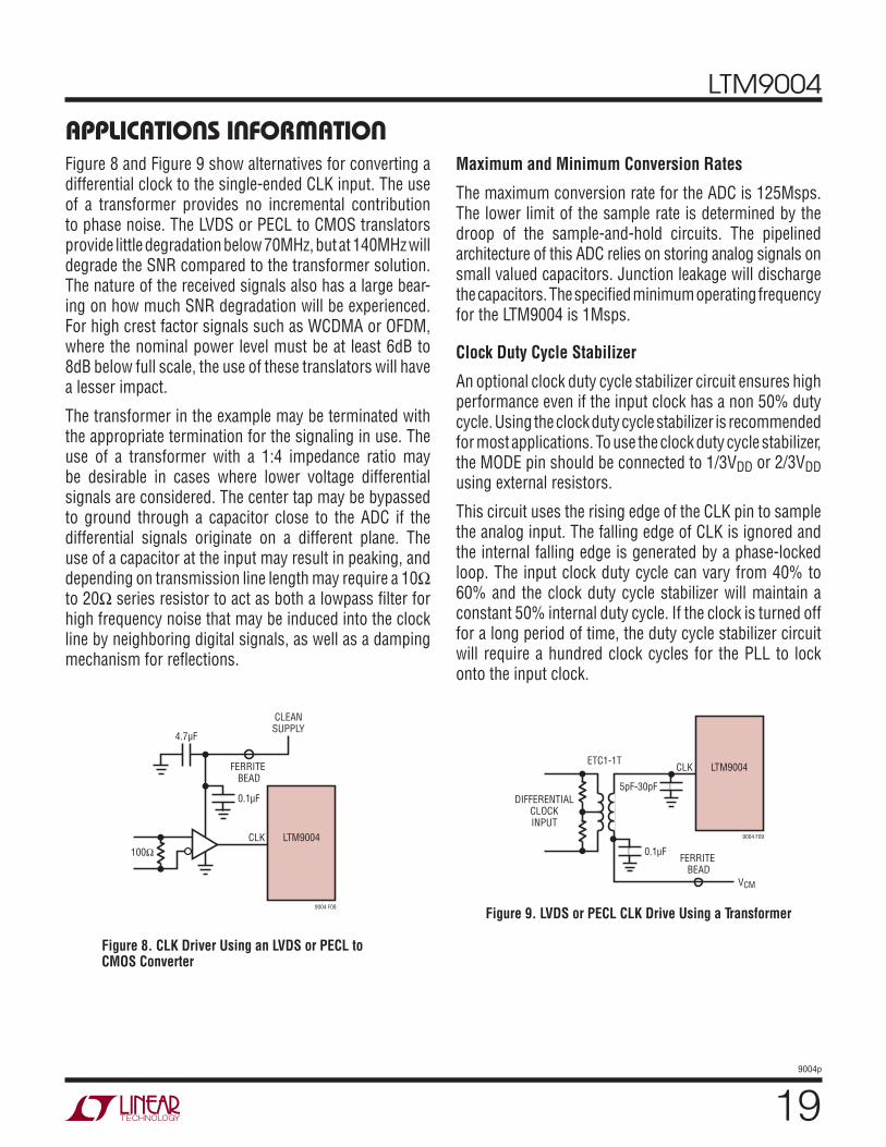
LTM9004
199004p
Figure 8 and Figure 9 show alternatives for converting a differential clock to the single-ended CLK input. The use of a transformer provides no incremental contribution to phase noise. The LVDS or PECL to CMOS translators provide little degradation below 70MHz, but at 140MHz will degrade the SNR compared to the transformer solution. The nature of the received signals also has a large bear-ing on how much SNR degradation will be experienced. For high crest factor signals such as WCDMA or OFDM, where the nominal power level must be at least 6dB to 8dB below full scale, the use of these translators will have a lesser impact.
The transformer in the example may be terminated with the appropriate termination for the signaling in use. The use of a transformer with a 1:4 impedance ratio may be desirable in cases where lower voltage differential signals are considered. The center tap may be bypassed to ground through a capacitor close to the ADC if the differential signals originate on a different plane. The use of a capacitor at the input may result in peaking, and depending on transmission line length may require a 10Ω to 20Ω series resistor to act as both a lowpass fi lter for high frequency noise that may be induced into the clock line by neighboring digital signals, as well as a damping mechanism for refl ections.
Maximum and Minimum Conversion Rates
The maximum conversion rate for the ADC is 125Msps. The lower limit of the sample rate is determined by the droop of the sample-and-hold circuits. The pipelined architecture of this ADC relies on storing analog signals on small valued capacitors. Junction leakage will discharge the capacitors. The specifi ed minimum operating frequency for the LTM9004 is 1Msps.
Clock Duty Cycle Stabilizer
An optional clock duty cycle stabilizer circuit ensures high performance even if the input clock has a non 50% duty cycle. Using the clock duty cycle stabilizer is recommended for most applications. To use the clock duty cycle stabilizer, the MODE pin should be connected to 1/3VDD or 2/3VDD using external resistors.
This circuit uses the rising edge of the CLK pin to sample the analog input. The falling edge of CLK is ignored and the internal falling edge is generated by a phase-locked loop. The input clock duty cycle can vary from 40% to 60% and the clock duty cycle stabilizer will maintain a constant 50% internal duty cycle. If the clock is turned off for a long period of time, the duty cycle stabilizer circuit will require a hundred clock cycles for the PLL to lock onto the input clock.
APPLICATIONS INFORMATION
Figure 8. CLK Driver Using an LVDS or PECL to CMOS Converter
Figure 9. LVDS or PECL CLK Drive Using a Transformer
CLK
100Ω
0.1μF
4.7μF
FERRITE BEAD
CLEANSUPPLY
9004 F08
LTM9004
CLK
5pF-30pF
ETC1-1T
0.1μF
VCM
FERRITE BEAD
DIFFERENTIALCLOCKINPUT
9004 F09
LTM9004

LTM9004
209004p
For applications where the sample rate needs to be changed quickly, the clock duty cycle stabilizer can be disabled. If the duty cycle stabilizer is disabled, care should be taken to make the sampling clock have a 50% (±5%) duty cycle.
DIGITAL OUTPUTS
Table 3 shows the relationship between the analog input voltage, the digital data bits, and the overfl ow bit. Note that OF is high when an overfl ow or underfl ow has occurred on either channel A or channel B.
Table 3. Output Codes vs Input Voltage
INPUT OF D13 – D0(OFFSET BINARY)
D13 – D0(2’S COMPLEMENT)
Overvoltage 1 11 1111 1111 1111 01 1111 1111 1111
Maximum 00
11 1111 1111 111111 1111 1111 1110
01 1111 1111 111101 1111 1111 1110
0000
10 0000 0000 000110 0000 0000 000001 1111 1111 111101 1111 1111 1110
00 0000 0000 000100 0000 0000 000011 1111 1111 111111 1111 1111 1110
Minimum00
00 0000 0000 000100 0000 0000 0000
10 0000 0000 000110 0000 0000 0000
Undervoltage 1 00 0000 0000 0000 10 0000 0000 0000
Digital Output Modes
Figure 10 shows an equivalent circuit for a single output buffer. Each buffer is powered by OVDD and OGND, iso-lated from the ADC power and ground. The additional N-channel transistor in the output driver allows operation down to low voltages. The internal resistor in series with the output makes the output appear as 50Ω to external circuitry and may eliminate the need for external damp-ing resistors.
As with all high speed/high resolution converters the digi-tal output loading can affect the performance. The digital outputs of the ADC should drive a minimal capacitive load to avoid possible interaction between the digital outputs and sensitive input circuitry. For full speed operation, the capacitive load should be kept under 10pF.
Lower OVDD voltages will also help reduce interference from the digital outputs.
Data Format
Using the MODE pin, the ADC parallel digital output can be selected for offset binary or 2’s complement format. Note that MODE controls both I and Q channels. Connecting MODE to GND or 1/3 VDD selects straight binary output format. Connecting MODE to 2/3 VDD or VDD selects 2’s complement output format. An external resistive divider can be used to set the 1/3 VDD or 2/3 VDD logic values. Table 4 shows the logic states for the MODE pin.
Table 4. MODE Pin Function
MODE PIN OUTPUT FORMAT CLOCK DUTY CYCLESTABILIZER
0 Straight Binary Off
1/3VDD Straight Binary On
2/3VDD 2’s Complement On
VDD 2’s Complement Off
Overfl ow Bit
When OF outputs a logic high the converter is either over-ranged or underranged on I-channel or Q-channel. Note that both channels share a common OF pin. OF is disabled when I-channel is in sleep or nap mode.
APPLICATIONS INFORMATION
Figure 10. Digital Output Buffer
LTM9004
9004 F10
OVDD
VDD VDD
0.1μF
43Ω TYPICALDATAOUTPUT
OGND
OVDD 0.5V TO 3.6V
PREDRIVERLOGIC
DATAFROMLATCH
OE

LTM9004
219004p
Output Clock
The ADC has a delayed version of the CLKQ input available as a digital output, CLKOUT. The falling edge of the CLKOUT pin can be used to latch the digital output data. CLKOUT is disabled when channel B is in sleep or nap mode.
Output Driver Power
Separate output power and ground pins allow the output drivers to be isolated from the analog circuitry. The power supply for the digital output buffers, OVDD, should be tied to the same supply that powers the logic being driven. For example, if the converter drives a DSP powered by a 1.8V supply, then OVDD should be tied to that same 1.8V supply.
OVDD can be powered with any voltage from 500mV up to the VDD of the part. OGND can be powered with any volt-age from GND up to 1V and must be less than OVDD. The logic outputs will swing between OGND and OVDD.
Output Enable
The outputs may be disabled with the output enable pin, OE. OE high disables all data outputs including OF. The data access and bus relinquish times are too slow to allow the outputs to be enabled and disabled during full speed operation. The output Hi-Z state is intended for use during long periods of inactivity. Channels I and Q have independent output enable pins (OEI, OEQ.)
Digital Output Multiplexer
The digital outputs of the ADC can be multiplexed onto a single data bus. The MUX pin is a digital input that swaps the two data busses. If MUX is high, I-channel comes out on DI0 to DI13; Q-channel comes out on DQ0 to DQ13. If MUX is low, the output busses are swapped and I-channel comes out on DQ0 to DQ13; Q-channel comes out on DI0 to DI13. To multiplex both channels onto a single output bus, connect MUX, CLKI and CLKQ together (see the Tim-ing Diagrams for the multiplexed mode.) The multiplexed data is available on either data bus – the unused data bus can be disabled with its OE pin.
APPLICATIONS INFORMATIONDesign Example – UMTS Uplink FDD System
The LTM9004 can be used with an RF front end to build a complete UMTS band uplink receiver. An RF front end will consist of a diplexer, along with one or more LNAs and bandpass fi lters. Here is an example of typical performance for such a frontend:
Rx frequency range: 1920 to 1980 MHz
RF gain: 23.5dB maximum
AGC range: 20dB
Noise fi gure: 1.6dB
IIP2: 50dBm
IIP3: 0dBm
P1dB: –9.5dBm
Rejection at 20MHz: 2dB
Rejection at Tx band: 96dB
Minimum performance of the receiver is detailed in the 3GPP TS25.104 V7.4.0 specifi cation. We will use the medium area basestation in operating band I for this example.
Sensitivity is a primary consideration for the receiver; the requirement is ≤–121dBm, for an input SNR of –19.8dB/5 MHz. That means the effective noise fl oor at the receiver input must be ≤–169.2dBm/Hz. Given the effective noise contribution of the RF frontend, the maximum allowable noise due to the LTM9004 must then be –148.5dBm/Hz. Typical input noise for the LTM9004 is –150dBm/Hz, which translates to a calculated system sensitivity of –121.7dBm.
To operate in the presence of co-channel interfering sig-nals, the receiver must have suffi cient dynamic range at maximum sensitivity. The UMTS specifi cation calls for a maximum co-channel interferer of –73dBm. At the LTM9004 input this amounts to –49.5dBm.
With the RF AGC set for minimum gain, the receiver must be able to demodulate the largest anticipated desired signal from the handset. Assuming a handset average power of

LTM9004
229004p
APPLICATIONS INFORMATION+28dBm, the minimum path loss called out in the specifi ca-tion is 53dB. The maximum signal level is then –25dBm at the receiver input, or –21.5dBm at the LTM9004 input. This requirement ultimately sets the maximum signal the LTM9004 must accommodate at or below –1dBFS.
There are several blocker signals detailed in the UMTS system specifi cation. Only a specifi ed amount of desen-sitization is allowed in the presence of these signals. The fi rst of these is an adjacent channel 5MHz away, at a level of –52dBm. The signal reaching the LTM9004 input will be –28.5dBm.
The receiver must also contend with a –40dBm interfer-ing channel ≥10MHz away. The RF frontend will offer no rejection of this channel, so it amounts to –16.5dBm at the LTM9004 input at an offset of ≥10MHz.
Out of band blockers must also be accommodated, but these are at the same level as the inband blockers which have already been addressed.
In all of these cases, the typical input level for –1dBFS of the LTM9004 is well above the maximum anticipated signal levels. Note that the crest factor for the modulated channels will be on the order of 10dB to 12dB, so the largest of these will reach a peak power of approximately –5dBm at the module input.
The largest blocking signal is the –15dBm CW tone ≥ 20MHz beyond the receive band edges. The RF frontend will of-fer only 2dB rejection of this tone, so it will appear at the input of the LTM9004 at +6.5dBm. Here again, a signal at this level must not desensitize the baseband module. The input P1dB of the LTM9004 is +11.2dBm, which will accommodate this signal.
Another source of undesired signal power is leakage from the transmitter. Since this is an FDD application, the re-ceiver described herein will be coupled with a transmitter operating simultaneously. The transmitter output level is assumed to be ≤+38dBm, with a transmit to receive isola-tion of 96dB. Leakage appearing at the LTM9004 input is then –34.5dBm, offset from the receive signal by at least 130MHz. As we have discussed above, this level of signal will not compress the module.
One challenge of direct conversion architectures is 2nd order linearity. Insuffi cient 2nd order linearity will allow any signal, wanted or unwanted, to create DC offset or pseudo-random noise at baseband. The blocking signals detailed above will then degrade sensitivity if this pseudo-random noise approaches the noise level of the receiver. The system specifi cation allows for sensitivity degrada-tion in the presence of these blockers in each case. Per the system specifi cation, the –40dBm blocking channel may degrade sensitivity to –115dBm. This is equivalent to increasing the effective input noise of the receiver to –163.2dBm/Hz. The allowable 2nd order distortion referred to the LTM9004 input is then –139.7dBm/Hz, with an input signal level of –16.5dBm applied. The 2nd order distortion produced in the LTM9004 will be much less than this, and resulting predicted sensitivity will be –116.9dBm.
The –15dBm CW blocker will also give rise to a 2nd order product; in this case the product is a DC offset. DC offset is undesirable, as it reduces the maximum signal the A/D converter can process. The one sure way to alleviate the effects of DC offset is to ensure the 2nd order linearity of the baseband module is high enough. Specifi ed DC offset due to this signal is 11mV.
Note that the transmitter leakage is not included in the system specifi cation, so the sensitivity degradation due to this signal must be held to a minimum. The 2nd order distortion generated in the LTM9004 is such that the loss of sensitivity will be <0.1dB.
There is only one requirement for 3rd order linearity in the specifi cation. In the presence of two interferers, the sensitivity must not degrade below –115dBm. The inter-ferers are a CW tone and a WCDMA channel at –48dBm each. These will appear at the LTM9004 input at –24.5dBm each. Their frequencies are such that they are 10MHz and 20MHz away from the desired channel, so the 3rd order intermodulation product falls at baseband. Here again, this product appears as pseudo-random noise and thus will reduce signal to noise ratio. For a sensitivity of –115dBm, the allowable 3rd order distortion referred to the LTM9004 input is then –139.7dBm/Hz. The 3rd order distortion produced in the LTM9004 will be much less than this, and the predicted sensitivity degradation is <0.1dB.

LTM9004
239004p
Supply Sequencing
The VCC pins provide the supply to the mixer and all ampli-fi ers and the VDD pins provide the supply to the ADC. The mixer, amplifi ers and ADC are separate integrated circuits within the LTM9004; however, there are no supply sequenc-ing considerations beyond standard practice.
Grounding and Bypassing
The LTM9004 requires a printed circuit board with a clean unbroken ground plane; a multilayer board with an internal ground plane is recommended. The pinout of the LTM9004 has been optimized for a fl owthrough layout so that the interaction between inputs and digital outputs is minimized. A continuous row of ground pads facilitate a layout that ensures that digital and analog signal lines are separated as much as possible.
The LTM9004 is internally bypassed with the ADC (VDD), mixer and amplifi er (VCC) supplies returning to a common ground (GND). The digital output supply (OVDD) is returned to OGND. A 0.1μF bypass capacitor should be placed at each of the two OVDD pins. Additional bypass capacitance is optional and may be required if power supply noise is signifi cant.
Heat Transfer
Most of the heat generated by the LTM9004 is transferred through the bottom-side ground pads. For good electrical and thermal performance, it is critical that all ground pins are connected to a ground plane of suffi cient area with as many vias as possible.
Recommended Layout
The high integration of the LTM9004 makes the PCB board layout simple. However, to optimize its electrical and thermal performance, some layout considerations are still necessary.
• Use large PCB copper areas for ground. This helps to dissipate heat in the package through the board and also helps to shield sensitive on-board analog signals. Common ground (GND) and output ground (OGND) are electrically isolated on the LTM9004, but can be connected on the PCB underneath the part to provide a common return path.
• Use multiple ground vias. Using as many vias as pos-sible helps to improve the thermal performance of the board and creates necessary barriers separating analog and digital traces on the board at high frequencies.
• Separate analog and digital traces as much as pos-sible, using vias to create high frequency barriers. This will reduce digital feedback that can reduce the signal-to-noise ratio (SNR) and dynamic range of the LTM9004.
Figures 11 through 14 give a good example of the recom-mended layout.
The quality of the paste print is an important factor in producing high yield assemblies. It is recommended to use a type 3 or 4 printing no-clean solder paste. The solder stencil design should follow the guidelines outlined in Application Note 100.
The LTM9004 employs gold-fi nished pads for use with Pb-based or tin-based solder paste. It is inherently Pb-free and complies with the JEDEC (e4) standard. The materi-als declaration is available online at http://www.linear.com/leadfree/mat_dec.jsp.
APPLICATIONS INFORMATION

LTM9004
249004p
APPLICATIONS INFORMATION
Figure 11. Layer 1
Figure 12. Layer 2

LTM9004
259004p
APPLICATIONS INFORMATION
Figure 13. Layer 3
Figure 14. Layer 4

LTM9004
269004p
TYPICAL APPLICATIONS
(Reserve this page for graphics to come.)

LTM9004
279004p
Information furnished by Linear Technology Corporation is believed to be accurate and reliable. However, no responsibility is assumed for its use. Linear Technology Corporation makes no representa-tion that the interconnection of its circuits as described herein will not infringe on existing patent rights.
PACKAGE DESCRIPTIONLGA Package
204-Lead (22mm × 15mm × 2.82mm)(Reference LTC DWG # 05-08-1822 Rev Ø)
1
2
3
4
5
6
7
8
10
9
11
12
13
14
15
16
17
L K J H G F E D C BM A
NOTES:1. DIMENSIONING AND TOLERANCING PER ASME Y14.5M-1994
2. ALL DIMENSIONS ARE IN MILLIMETERS
LAND DESIGNATION PER JESD MO-222
5. PRIMARY DATUM -Z- IS SEATING PLANE
6. THE TOTAL NUMBER OF PADS: 204
4
3
DETAILS OF PAD #1 IDENTIFIER ARE OPTIONAL,BUT MUST BE LOCATED WITHIN THE ZONE INDICATED.THE PAD #1 IDENTIFIER MAY BE EITHER A MOLD OR MARKED FEATURE
SYMBOL
aaa
bbb
eee
TOLERANCE
0.15
0.10
0.05
2.670 – 2.970
DETAIL B
DETAIL B
SUBSTRATEMOLDCAP
0.27 – 0.37
2.40 – 2.60
bbb Z Z
22BSC
PACKAGE TOP VIEW
15BSC
4
PAD 1CORNER
XY
aaa Z
aaa Z
20.32BSC
1.27BSC
0.12 – 0.28
PACKAGE BOTTOM VIEW3
PADSSEE NOTES
DETAIL A
0.635 ±0.025 SQ. 204x
S YXeee
SUGGESTED PCB LAYOUTTOP VIEW
0.0000
1.2700
1.2700
2.5400
2.5400
3.8100
3.8100
5.0800
5.0800
6.3500
6.3500
7.6200
8.8900
10.1600
6.9
850
6.9
850
5.7
150
5.7
150
4.4
450
4.4
450
3.1
750
3.1
750
1.9
050
1.9
050
0.6
350
0.6
350
0.0
000
7.6200
8.8900
10.1600
LGA 204 0108 REV Ø
LTMXXXXXXμModule
TRAY PIN 1BEVEL
PACKAGE IN TRAY LOADING ORIENTATION
COMPONENTPIN “A1”
Ø(0.635)PAD 1
DETAIL A
13.97BSC

LTM9004
289004p
Linear Technology Corporation1630 McCarthy Blvd., Milpitas, CA 95035-7417 (408) 432-1900 FAX: (408) 434-0507 www.linear.com © LINEAR TECHNOLOGY CORPORATION 2010
LT 1010 • PRINTED IN USA
RELATED PARTSPART NUMBER DESCRIPTION COMMENTS
LTC2295 Dual 14-Bit, 10Msps ADC 120mW, 74.4dB SNR, 9mm x 9mm QFN
LTC2296 Dual 14-Bit, 25Msps ADC 150mW, 74dB SNR, 9mm x 9mm QFN
LTC2297 Dual 14-Bit, 40Msps ADC 240mW, 74dB SNR, 9mm x 9mm QFN
LTC2298 Dual 14-Bit, 65Msps ADC 410mW, 74dB SNR, 9mm x 9mm QFN
LTC2299 Dual 14-Bit, 80Msps ADC 445mW, 73dB SNR, 9mm x 9mm QFN
LTC2284 Dual 14-Bit, 105Msps ADC 540mW, 72.4dB SNR, 88dB SFDR, 64-pin QFN
LTC2285 Dual 14-Bit, 125Msps ADC 790mW, 72.4dB SNR, 88dB SFDR, 64-pin QFN
LT5575 800MHz to 2.7GHz High Linearity Direct Conversion Quadrature Demodulator
60dBm IIP2 at 1.9GHz, NF = 12.7dB, Low DC Offsets
LTC6404-1/ LTC6404-2
600MHz, Low Noise, AC Precision Fully Differential Input/Output Amplifier/Driver
3V or 5V, 1.5nV/√Hz, Very Low Distortion –92dBc at 10MHz
LTC6406 3GHz Low Noise, Rail-to-Rail Input Differential ADC Driver
Low Noise: 1.6nV/√Hz, Low Power: 18μA
LTM9001 16-Bit IF/Baseband Receiver Subsystem Integrated 16-Bit, 130Msps ADC, Passive Filter and Fixed Gain Differential Amplifi er, 11.25mm × 11.25mm LGA Package
LTM9002 14-Bit Dual-Channel IF/Baseband Receiver Subsystem
Integrated, Dual 14-Bit 125Msps ADCs, Passive Filters and Fixed Gain Differential Amplifi ers, Up to 300MHz IF Range, 15mm × 11.25mm LGA Package
LTM9005 14-Bit, IF-Sampling Receiver Subsystem Integrated 14-Bit, 125Msps ADC, SAW Filter, Two Gain Stages with 20dB Variable Gain Control and RF Mixer, 22mm × 15mm LGA Package
TYPICAL APPLICATION
VCC1 = 5V
9004 TA02
0°
90°
LOI+_ADJ
LTM9004
I–_ADJ Q+_ADJ Q–_ADJ
~CS/LD
SDI
SCK
SDO
0.1μFLTC2634-12 (OR LTC2654-16)
RF
REF
0.1μF
VCC = 5V