Embed Size (px)
Citation preview

DELTA · Venlighedsvej 4 · 2970 Hørsholm · Denmark · Tel. +45 72 19 40 00 · [email protected]
LTL-X Mark II RETROREFLEKTROMETER
User Manual
On site quality control of road markings & road surfaces in accordance with CEN / ASTM
2 LTL-X Mark II Retroreflectometer DELTA
DISCLAIMER The information contained in this document is subject to change without notice. DELTA LIGHT & OPTICS MAKES NO WARRANTY OF ANY KIND WITH REGARD TO THIS MATERIAL, INCLUD-ING, BUT NOT LIMITED TO, THE IMPLIED WARRANTIES OF MERCHANTABILITY AND FITNESS FOR A PARTICU-LAR PURPOSE. DELTA LIGHT & OPTICS SHALL NOT BE LIABLE FOR ERRORS CONTAINED HEREIN OR FOR INCIDENTAL OR CONSEQUENTIAL DAMAGES IN CONNECTION WITH THE FURNISHING, PERFORMANCE OR USE OF THIS MATERIAL. LTL-X Mark II IS BUILT ON GENERAL PUBLIC LICENSE COMPONENTS. THE SOURCS CODE IS AVAILABLE UPON REQUEST. Caution: Changes / modifications not approved by the re-sponsible party could void the user’s authority to operate the equipment. NOTE: This equipment has been tested and found to comply with the limits for a Class A digital device, pursuant to part 15 of the FCC Rules. These limits are designed to provide reasonable protection against harmful interference when the equipment is operated in a commercial environment. This equipment generates, uses, and can radiate radio frequency energy and, if not installed and used in accordance with the instruction manual, may cause harmful interference to radio communications. Operation of this equipment in a residential area is likely to cause harmful interference in which case the user will be required to correct the interference at his / her own expense.
GUI 2.00, August 2016
Version 1.2c English
Visit our web-site: www.roadsensors.com
DELTA LTL-X Mark II Retroreflectometer 3
4 LTL-X Mark II Retroreflectometer DELTA
DELTA LTL-X Mark II Retroreflectometer 5
TABLE OF CONTENTS
SECTION 1 ................................................................................................................................ 7
OPERATING INFORMATION ...................................................................................................... 7 LTL-X Mark II introduction ..................................................................................................................... 7 LTL-X Mark II retroreflectometer features .............................................................................................. 8 Getting started ........................................................................................................................................... 9
Height adjustment ................................................................................................................................ 9 Buttons ................................................................................................................................................. 9 Turn on ................................................................................................................................................. 9 Measuring ............................................................................................................................................ 9 User select (user initials) .................................................................................................................... 10 Series Id select (name) ....................................................................................................................... 10 Errors and warnings ........................................................................................................................... 10 Miscellaneous .................................................................................................................................... 10 Data exchange / communication ........................................................................................................ 11
Important guide lines for the correct use of the LTL-X Mark II ............................................................. 11 Positioning of the instrument on the road marking ............................................................................ 11 Taking the measurement .................................................................................................................... 11 Number of measurements. ................................................................................................................. 11 Protection of the display/display shield. ............................................................................................ 11
SECTION 2 .............................................................................................................................. 12
GENERAL INFORMATION ........................................................................................................ 12 The measurement .................................................................................................................................... 12 Errors and warnings ................................................................................................................................ 12 Optical principle ..................................................................................................................................... 12 Notes on error sources ............................................................................................................................ 13 High temperature conditions. .................................................................................................................. 14
Display ............................................................................................................................................... 14 Battery ................................................................................................................................................ 14
SECTION 3 .............................................................................................................................. 15
THE USER INTERFACE .............................................................................................................. 15 Display and keyboard layout .................................................................................................................. 15 Measurement display .............................................................................................................................. 15 Upper icon row ....................................................................................................................................... 15 Lower icon row ....................................................................................................................................... 16 Push buttons ............................................................................................................................................ 16 The menu tree ......................................................................................................................................... 18
SETTING UP FOR MEASUREMENTS ...................................................................................... 19 Selecting a User Id .................................................................................................................................. 19
Selecting a user. ................................................................................................................................. 19 Selecting a road marking icon ................................................................................................................ 21
The purpose of the road marking icon. .............................................................................................. 21 Deactivating the profile icon. ............................................................................................................. 21
Setting the date and time ......................................................................................................................... 21 Setting the time format ....................................................................................................................... 22 Setting the date format ....................................................................................................................... 22 Adjusting the time and date ............................................................................................................... 22
Setting the dimmer and back light for the display .................................................................................. 23 Setting the sound..................................................................................................................................... 23 Auto Sleep (Power) ................................................................................................................................. 24 Setting the language ................................................................................................................................ 24 Setting the temperature unit .................................................................................................................... 24 Setting the SMART key function ........................................................................................................... 25 Setting the AUX functions / GPS ........................................................................................................... 25
Activating the GPS ............................................................................................................................ 26 More about the GPS ........................................................................................................................... 26
Setup (basic / advanced) ......................................................................................................................... 27
6 LTL-X Mark II Retroreflectometer DELTA
MEASURE TYPE ........................................................................................................................... 28 Wet timer ................................................................................................................................................ 28 Timer Alarm ........................................................................................................................................... 28
Series id ............................................................................................................................................ 29 Working with Series Id ........................................................................................................................... 29
The purpose of a Series Id .................................................................................................................. 29 Activate Series ........................................................................................................................................ 29 Selecting a Series Id ................................................................................................................................ 29 Enter a new Series Id .............................................................................................................................. 30 Edit a Series Id ........................................................................................................................................ 30 Removing a Series Id .............................................................................................................................. 30 Presetting the road marking icon ............................................................................................................ 31
The log .............................................................................................................................................. 32 Clearing data in the log ........................................................................................................................... 32 Viewing the log....................................................................................................................................... 33 View series data. ..................................................................................................................................... 34
OTHER SETTINGS ....................................................................................................................... 35 Average function .................................................................................................................................... 35
AVERAGE: ....................................................................................................................................... 35 TYPE: ................................................................................................................................................ 35 NUMBER: ......................................................................................................................................... 35 RESET: .............................................................................................................................................. 35
Editing names ......................................................................................................................................... 36 Auto print ................................................................................................................................................ 36 Diagnostics ............................................................................................................................................. 36 The help system ...................................................................................................................................... 36
SECTION 4 .............................................................................................................................. 37
MAINTENANCE ............................................................................................................................ 37 General care ............................................................................................................................................ 37 Protection window .................................................................................................................................. 37 Battery .................................................................................................................................................... 37
Replacing the battery ......................................................................................................................... 38 Battery status ...................................................................................................................................... 39
Fuses ....................................................................................................................................................... 39 Lamp ....................................................................................................................................................... 39 Calibration .............................................................................................................................................. 40
Calibration procedure ......................................................................................................................... 40 Verification procedure ....................................................................................................................... 42 Keep the calibration ceramic in good condition! ............................................................................... 42 Calibration service ............................................................................................................................. 42
Printer ..................................................................................................................................................... 43 Replacing paper ................................................................................................................................. 43
Mounting the wet night rails for rain measurements .............................................................................. 44 Mounting the wheel unit ......................................................................................................................... 46
APPENDIX A .......................................................................................................................... 47
COMMUNICATION FACILITIES .............................................................................................. 47 RSC software program............................................................................................................................ 47
APPENDIX B .......................................................................................................................... 48
SPECIFICATION ........................................................................................................................... 48 General characteristics ............................................................................................................................ 48 Environmental characteristics ................................................................................................................. 49 Mechanical characteristics ...................................................................................................................... 49
APPENDIX C .......................................................................................................................... 50
DELIVERY ..................................................................................................................................... 50
DELTA LTL-X Mark II Retroreflectometer 7
SECTION 1
OPERATING INFORMATION
LTL-X Mark II introduction
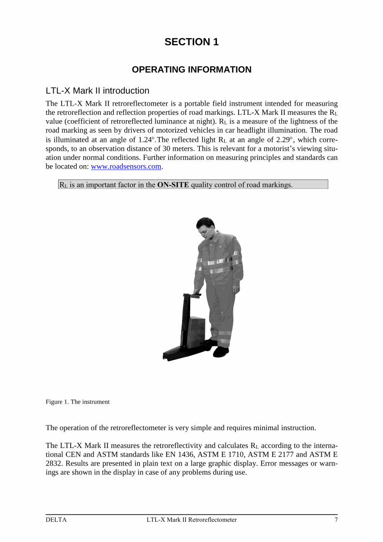
The LTL-X Mark II retroreflectometer is a portable field instrument intended for measuring
the retroreflection and reflection properties of road markings. LTL-X Mark II measures the RL
value (coefficient of retroreflected luminance at night). RL is a measure of the lightness of the
road marking as seen by drivers of motorized vehicles in car headlight illumination. The road
is illuminated at an angle of 1.24The reflected light RL at an angle of 2.29, which corre-
sponds, to an observation distance of 30 meters. This is relevant for a motorist’s viewing situ-
ation under normal conditions. Further information on measuring principles and standards can
be located on: www.roadsensors.com.
Figure 1. The instrument
The operation of the retroreflectometer is very simple and requires minimal instruction.
The LTL-X Mark II measures the retroreflectivity and calculates RL according to the interna-
tional CEN and ASTM standards like EN 1436, ASTM E 1710, ASTM E 2177 and ASTM E
2832. Results are presented in plain text on a large graphic display. Error messages or warn-
ings are shown in the display in case of any problems during use.
RL is an important factor in the ON-SITE quality control of road markings.
8 LTL-X Mark II Retroreflectometer DELTA
The memory of the instrument provides registration of measurements with corresponding
date, time and following data (if enabled):
Name of measuring series (road name)
Profile icon for road marking type
User name
GPS data (if installed)
Temperature & humidity
Instrument status
The measurement results can be printed by the built-in printer. Communication with a PC us-
ing the LTL RSC (Road Sensor Control) software program (see pg. 47) allows for data ex-
change with other PC programs.
A rechargeable NiMH (Nickel-Metal Hydride) High capacity battery powers the LTL-X Mark
II, allowing approx. 2.500 measurements on a new and fully charged battery. A mains pow-
ered 15V power adaptor for charging (the instrument has a built-in charging circuit) is sup-
plied as customary delivery. Charging time is approx. 3½ hour. The instrument can also be
charged from a 15-18 VDC source. For field charging the 15V power supply could be pow-
ered from an “AC power inverter” connected to the car battery.
LTL-X Mark II retroreflectometer features
Portable instrument
Ergonomic operation height
Fast measurement. Completed in approximately 1 sec.
Measuring on dry and wet surfaces as well as under continuous wetting
Flat, textured & profiled markings
Fully documented measurements with automatic data storage, user and series identi-
fication for labeling and grouping measurements
Audible signals during use (if enabled)
Easy one-step calibration procedure
Traceable and accredited calibrated reflection standard
User replaceable battery
Battery charging time is approx. 3½ hour for high capacity battery pack
Rechargeable from mains using power adapter
Average calculation of 2 to 99 readings
Multiple languages
RSC (Road Sensor Control) PC software for data exchange. Logged data can
easily be exported to applications such as Microsoft Excel or displayed on Gog-
gle Earth
LTL-X Mark II comes as customary delivery with extendable handle, wheels, built-in printer
and built-in GPS.
DELTA LTL-X Mark II Retroreflectometer 9
Getting started
Height adjustment
Before using the LTL-X Mark II, notice that the operating panel can be adjusted in height
for ergonomic considerations. The height is adjusted by pressing the red knob on the front
of the instrument and at the same time lifting the handle on the operating panel. Release
the knob and continue lifting until the handle locks.
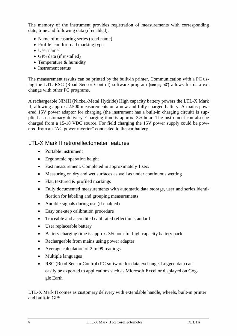
Buttons
HELP ON/OFF
MENU SMART
HOME CALIBRATE
BACK PRINT
UP
LEFT RIGHT
OK (center)
DOWN Figure 2.Buttons
For more information about buttons: see pg. 16
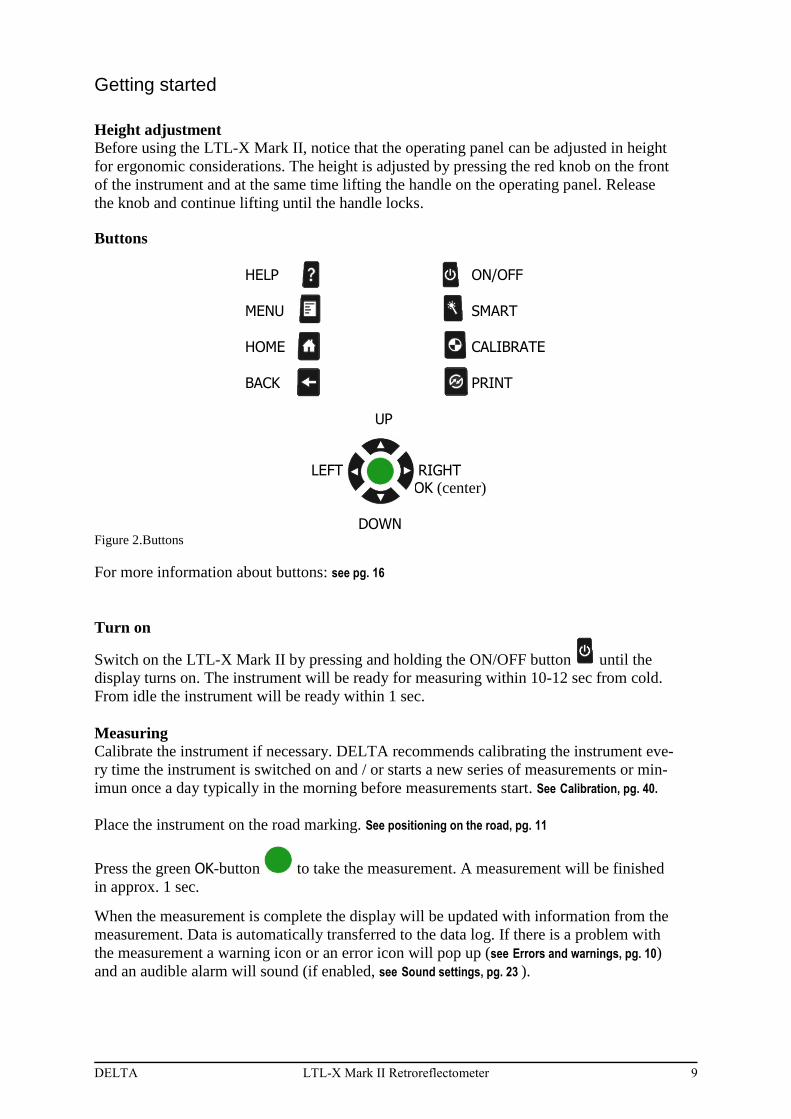
Turn on
Switch on the LTL-X Mark II by pressing and holding the ON/OFF button until the
display turns on. The instrument will be ready for measuring within 10-12 sec from cold.
From idle the instrument will be ready within 1 sec.
Measuring
Calibrate the instrument if necessary. DELTA recommends calibrating the instrument eve-
ry time the instrument is switched on and / or starts a new series of measurements or min-
imun once a day typically in the morning before measurements start. See Calibration, pg. 40.
Place the instrument on the road marking. See positioning on the road, pg. 11
Press the green OK-button to take the measurement. A measurement will be finished
in approx. 1 sec. When the measurement is complete the display will be updated with information from the
measurement. Data is automatically transferred to the data log. If there is a problem with
the measurement a warning icon or an error icon will pop up (see Errors and warnings, pg. 10)
and an audible alarm will sound (if enabled, see Sound settings, pg. 23 ).
10 LTL-X Mark II Retroreflectometer DELTA
Measurements taken with a low battery warning are marked in the log and a warning icon
appears. If battery voltage gets too low measurements can’t be taken and an error icon ap-
pears.
To print out the last measurement data, press the PRINT button .
User select (user initials)
If the User icon is displayed in the upper icon row on the measuring display, press the
UP button ▲ (and if necessary ◄ or ►) to mark the user icon. Press the OK-button to
enter the user select menu.
If icon is not shown or if further information is need, see User Id, pg. 19.
Series Id select (name)
If the Series Id icon is displayed in the upper icon row on the measuring display press
the UP button ▲to mark the road icon. Press the OK-button to enter the Series Id se-
lect menu. Choose SELECT to use a name from the list.
If the icon is not shown or if further information is need, see Series Id, pg. 29.
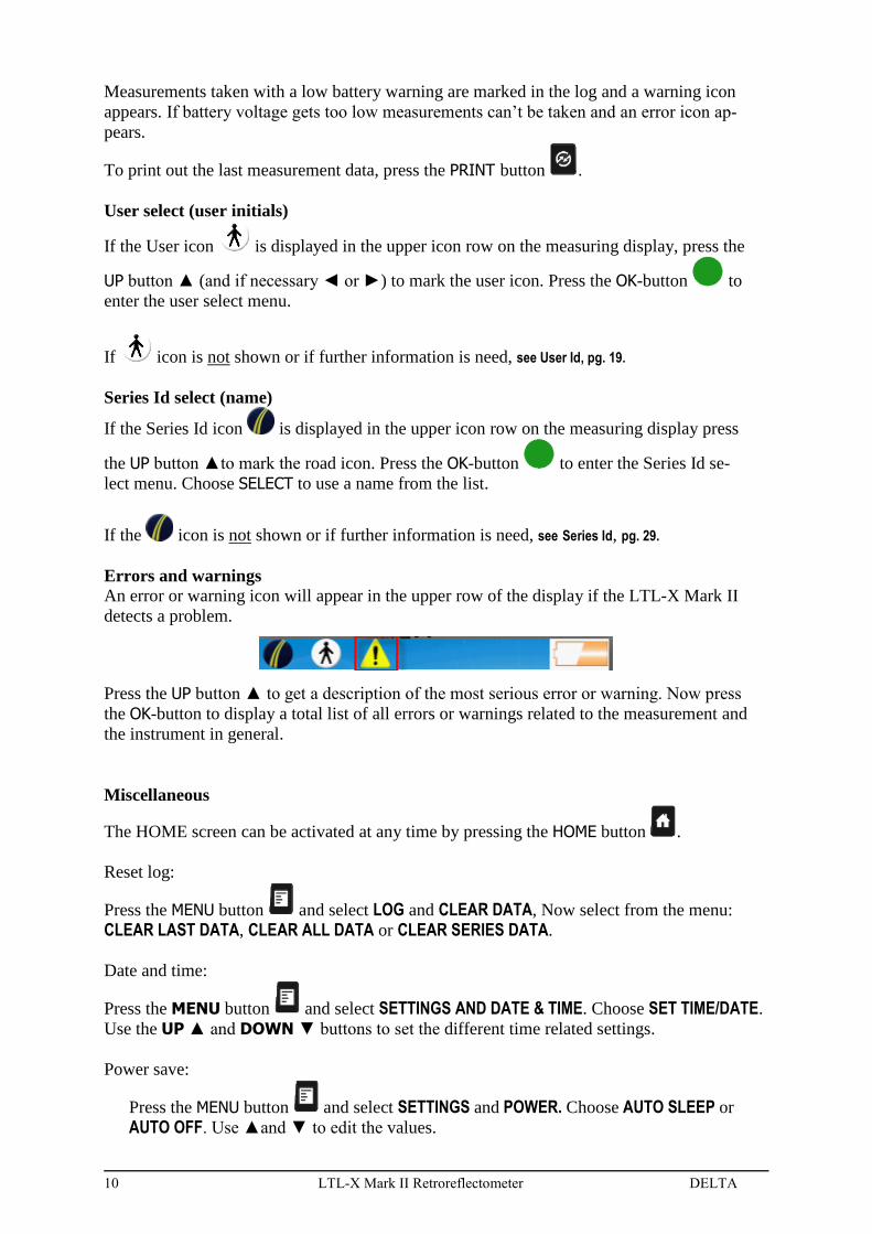
Errors and warnings An error or warning icon will appear in the upper row of the display if the LTL-X Mark II
detects a problem.
Press the UP button ▲ to get a description of the most serious error or warning. Now press
the OK-button to display a total list of all errors or warnings related to the measurement and
the instrument in general.
Miscellaneous
The HOME screen can be activated at any time by pressing the HOME button .
Reset log:
Press the MENU button and select LOG and CLEAR DATA, Now select from the menu:
CLEAR LAST DATA, CLEAR ALL DATA or CLEAR SERIES DATA.
Date and time:
Press the MENU button and select SETTINGS AND DATE & TIME. Choose SET TIME/DATE.
Use the UP ▲ and DOWN ▼ buttons to set the different time related settings.
Power save:
Press the MENU button and select SETTINGS and POWER. Choose AUTO SLEEP or AUTO OFF. Use ▲and ▼ to edit the values.
DELTA LTL-X Mark II Retroreflectometer 11
Data exchange / communication
The RSC software program, developed by DELTA for use on a PC, allows data to be ex-
changed between the LTL-X Mark II and a PC. See RSC-program, pg. 47.
Important guide lines for the correct use of the LTL-X Mark II
Positioning of the instrument on the road marking
Select an area of the pavement marking that is level when taking readings. The measurement
field is marked with a yellow sticker on one side of the base cover. The measurement field is
approximately 45 mm / 1.77 inch wide and 200 mm / 7.87 inch long. Ensure that the pave-
ment marking to be measured is free of debris before taking measurements. Make sure that
the instrument is stable positioned.
Reason: The LTL-X Mark II has three support pads, each with a small footprint, two smaller
in the front and one larger at the back. An uneven marking or a small piece of gravel trapped
below one of the pads will move the measurement field and affect the reading.
Taking the measurement
Press the OK-button to take a reading. Do not put pressure on the handle when taking a
measurement.
Reason: Pressure on the handle can tilt the instrument slightly and affect the measurement
geometry and therefore influence the reading.
Number of measurements.
For accurate readings, do not take just one reading of a road marking. Three readings will
give a more accurate result than one reading. Five readings will give an even more accurate
result than three readings, etc. Take the readings in adjacent areas of the marking. Let the in-
strument calculate the average of the readings (fixed or moving average options). See pg. 35
Reason: A road marking’s retroreflectivity varies from area to area. It is not unusual to see
variations of 5% - 20% when the instrument is moved even less than 12 mm / ½” in either
direction.
Protection of the display/display shield.
For the protection of the display and longevity of the instruments keep the display shield
closed when the instrument is not used. For further information please see High temperature condi-
tions, pg. 14.
Remember:
Read:
LTL-X Mark II is an optical precision instrument, handle with care.
Keep the protection window and calibration unit clean and undamaged.
Store in a clean, dust free and dry environment.
“Measurement practice for road markings”. This leaflet can be located on:
www.roadsensors.com under “Technical Background” and “Introduction”
12 LTL-X Mark II Retroreflectometer DELTA
SECTION 2
GENERAL INFORMATION
The measurement
The LTL-X Mark II retroreflectometer measures the RL (coefficient of retroreflected lumi-
nance) parameter. The RL parameter represents the brightness of road markings seen by driv-
ers of motor vehicles by headlight illumination.
In the LTL-X Mark II the illumination angle is 1.24 degrees for RL. The observation angles
are 2.29 degrees. According to both ASTM and CEN standards these angle simulates a driv-
er’s viewing distance of 30 meters. The instrument’s illumination field is approximately
200 mm x 45 mm / 7.87 x 1.77 inch.
The LTL-X Mark II is controlled by multiple microprocessors. It is operated with an extracta-
ble keyboard located at the top of the retroreflectometer.
Push the button to take a measurement. Shortly after, the RL and related information are
presented on the color display. The result is automatically transferred to the internal memory.
The measurement, along with its corresponding time, date, and other data can be printed using
the built-in printer.
Each time a measurement is taken, a status information is generated. If any error occurs the
information can be interpreted by the warning/error icon in the top line of the display. The
information is available until a new measurement is taken or the problem is resolved. The sta-
tus information is also stored in the log.
Errors and warnings
When a measurement is taken, a warning text is generated if a problem arises and saved in the
log together with the measurement. If a problem occurs, a warning icon or an error icon
is show above the HOME screen and an audible alarm is sounded (if enabled) and the
warning / error information are stored in the log.
To view the nature of the problem, press the UP button and the warning/error icon will be
highlighted. The most severe problem will be stated in the message line underneath.
Then press the OK button to view a total list of problems starting with the most severe.
Press the BACK button to return to the HOME screen. If the problem did not hinder the com-
pletion of the measurement, the erroneous value(s) will be stored in the log. If an error is reg-
istered the measurement will not be stored in the log.
When printing out, on the built-in printer, or transferring logged data to a PC using the RSC
program, any trouble will be shown in clear text on the concerned measurement.
Optical principle
The optical system in the LTL-X Mark II is covered by a patent. A LED lamp in the top of the
tower generates the light for the RL measurements. After a field stop the light is collimated by
a lens and deflected through a mirror toward the road.
DELTA LTL-X Mark II Retroreflectometer 13
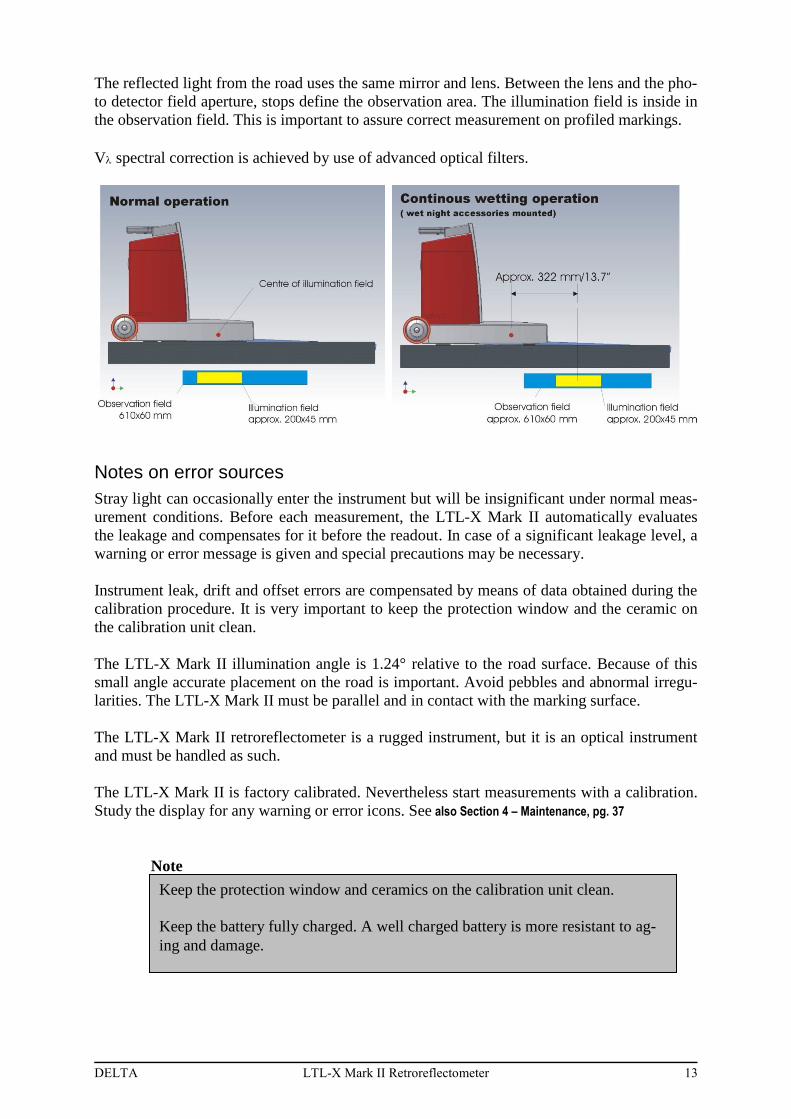
The reflected light from the road uses the same mirror and lens. Between the lens and the pho-
to detector field aperture, stops define the observation area. The illumination field is inside in
the observation field. This is important to assure correct measurement on profiled markings.
V spectral correction is achieved by use of advanced optical filters.
Notes on error sources
Stray light can occasionally enter the instrument but will be insignificant under normal meas-
urement conditions. Before each measurement, the LTL-X Mark II automatically evaluates
the leakage and compensates for it before the readout. In case of a significant leakage level, a
warning or error message is given and special precautions may be necessary.
Instrument leak, drift and offset errors are compensated by means of data obtained during the
calibration procedure. It is very important to keep the protection window and the ceramic on
the calibration unit clean.
The LTL-X Mark II illumination angle is 1.24° relative to the road surface. Because of this
small angle accurate placement on the road is important. Avoid pebbles and abnormal irregu-
larities. The LTL-X Mark II must be parallel and in contact with the marking surface.
The LTL-X Mark II retroreflectometer is a rugged instrument, but it is an optical instrument
and must be handled as such.
The LTL-X Mark II is factory calibrated. Nevertheless start measurements with a calibration.
Study the display for any warning or error icons. See also Section 4 – Maintenance, pg. 37
Note
Keep the protection window and ceramics on the calibration unit clean.
Keep the battery fully charged. A well charged battery is more resistant to ag-
ing and damage.

14 LTL-X Mark II Retroreflectometer DELTA
High temperature conditions.
Display
If the display is exposed to intense direct sunlight during a longer period of time the display
could become overheated. It is recommended to close the protective display shield. The shield
also protects against damages and scratches. "Daylight readable" displays are vulnerable to
high temperatures. High temperature will decrease the display service life.
Battery
The battery is rated to operate between 0C / 32F and 45C / 113F.
DELTA LTL-X Mark II Retroreflectometer 15
SECTION 3
THE USER INTERFACE
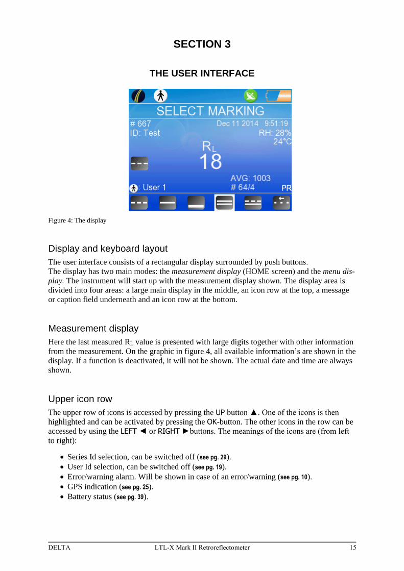
Figure 4: The display
Display and keyboard layout
The user interface consists of a rectangular display surrounded by push buttons.
The display has two main modes: the measurement display (HOME screen) and the menu dis-
play. The instrument will start up with the measurement display shown. The display area is
divided into four areas: a large main display in the middle, an icon row at the top, a message
or caption field underneath and an icon row at the bottom.
Measurement display
Here the last measured RL value is presented with large digits together with other information
from the measurement. On the graphic in figure 4, all available information’s are shown in the
display. If a function is deactivated, it will not be shown. The actual date and time are always
shown.
Upper icon row
The upper row of icons is accessed by pressing the UP button ▲. One of the icons is then
highlighted and can be activated by pressing the OK-button. The other icons in the row can be
accessed by using the LEFT ◄ or RIGHT ►buttons. The meanings of the icons are (from left
to right):
Series Id selection, can be switched off (see pg. 29).
User Id selection, can be switched off (see pg. 19).
Error/warning alarm. Will be shown in case of an error/warning (see pg. 10).
GPS indication (see pg. 25).
Battery status (see pg. 39).
16 LTL-X Mark II Retroreflectometer DELTA
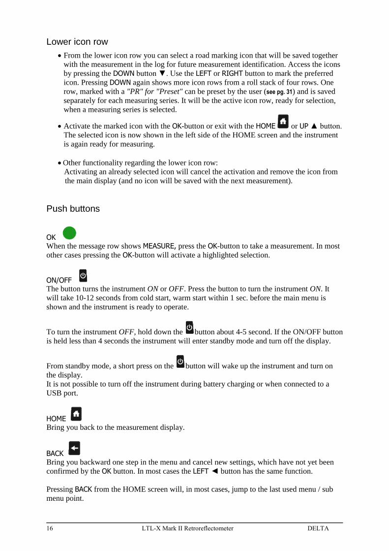
Lower icon row
From the lower icon row you can select a road marking icon that will be saved together
with the measurement in the log for future measurement identification. Access the icons
by pressing the DOWN button ▼. Use the LEFT or RIGHT button to mark the preferred
icon. Pressing DOWN again shows more icon rows from a roll stack of four rows. One
row, marked with a "PR" for "Preset" can be preset by the user (see pg. 31) and is saved
separately for each measuring series. It will be the active icon row, ready for selection,
when a measuring series is selected.
Activate the marked icon with the OK-button or exit with the HOME or UP ▲ button.
The selected icon is now shown in the left side of the HOME screen and the instrument
is again ready for measuring.
Other functionality regarding the lower icon row:
Activating an already selected icon will cancel the activation and remove the icon from
the main display (and no icon will be saved with the next measurement).
Push buttons
OK When the message row shows MEASURE, press the OK-button to take a measurement. In most
other cases pressing the OK-button will activate a highlighted selection.
ON/OFF The button turns the instrument ON or OFF. Press the button to turn the instrument ON. It
will take 10-12 seconds from cold start, warm start within 1 sec. before the main menu is
shown and the instrument is ready to operate.
To turn the instrument OFF, hold down the button about 4-5 second. If the ON/OFF button
is held less than 4 seconds the instrument will enter standby mode and turn off the display.
From standby mode, a short press on the button will wake up the instrument and turn on
the display.
It is not possible to turn off the instrument during battery charging or when connected to a
USB port.
HOME Bring you back to the measurement display.
BACK Bring you backward one step in the menu and cancel new settings, which have not yet been
confirmed by the OK button. In most cases the LEFT ◄ button has the same function.
Pressing BACK from the HOME screen will, in most cases, jump to the last used menu / sub
menu point.
DELTA LTL-X Mark II Retroreflectometer 17
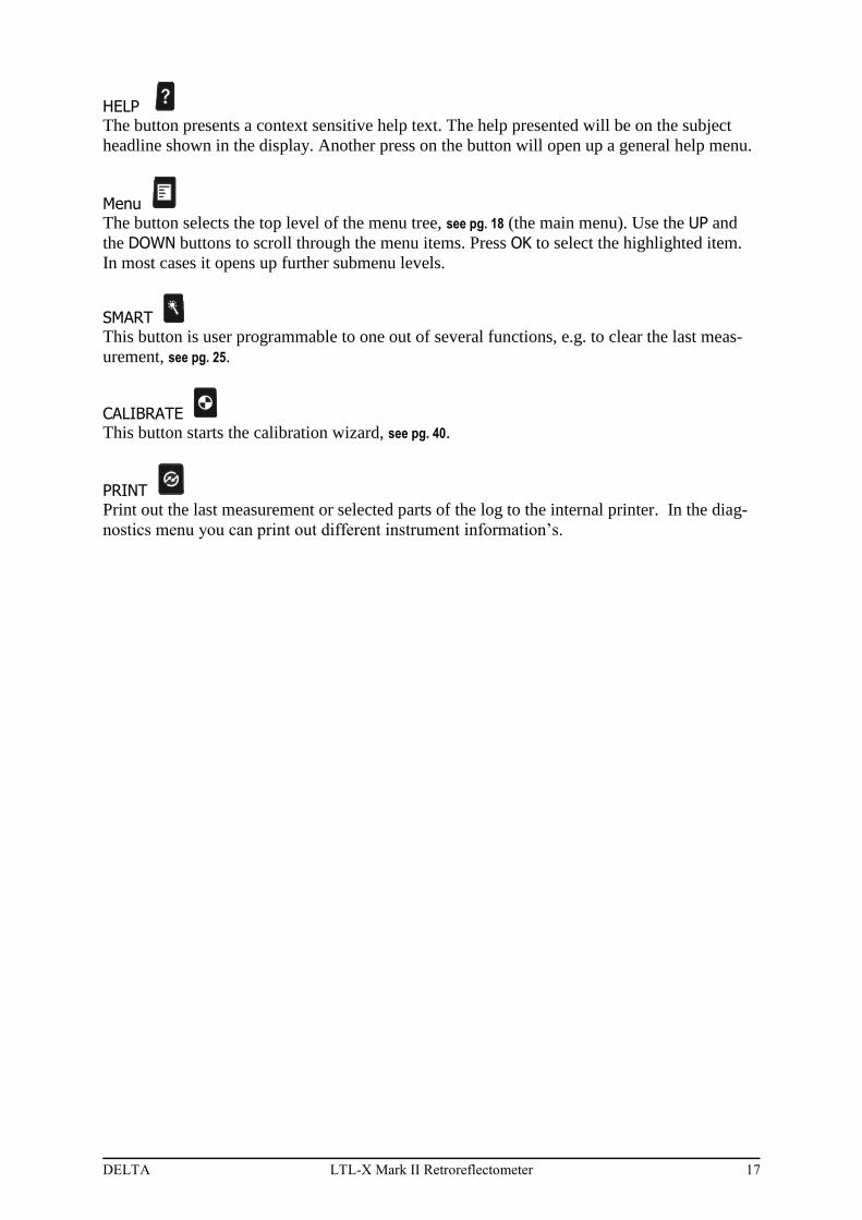
HELP The button presents a context sensitive help text. The help presented will be on the subject
headline shown in the display. Another press on the button will open up a general help menu.
Menu The button selects the top level of the menu tree, see pg. 18 (the main menu). Use the UP and
the DOWN buttons to scroll through the menu items. Press OK to select the highlighted item.
In most cases it opens up further submenu levels.
SMART This button is user programmable to one out of several functions, e.g. to clear the last meas-
urement, see pg. 25.
CALIBRATE This button starts the calibration wizard, see pg. 40.
PRINT Print out the last measurement or selected parts of the log to the internal printer. In the diag-
nostics menu you can print out different instrument information’s.
18 LTL-X Mark II Retroreflectometer DELTA
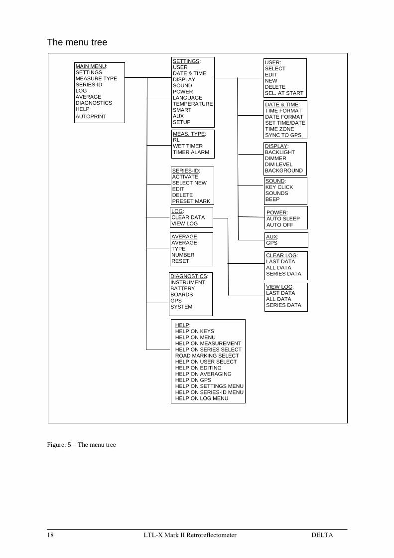
The menu tree
Figure: 5 – The menu tree
MAIN MENU: SETTINGS MEASURE TYPE SERIES-ID LOG AVERAGE DIAGNOSTICS HELP
AUTOPRINT
SETTINGS: USER DATE & TIME DISPLAY SOUND POWER LANGUAGE TEMPERATURE SMART AUX SETUP
SERIES-ID: ACTIVATE SELECT NEW EDIT DELETE PRESET MARK
AUX: GPS
SOUND: KEY CLICK SOUNDS BEEP
DISPLAY: BACKLIGHT DIMMER DIM LEVEL BACKGROUND
DATE & TIME: TIME FORMAT DATE FORMAT SET TIME/DATE TIME ZONE SYNC TO GPS
USER: SELECT EDIT NEW DELETE SEL. AT START
DIAGNOSTICS: INSTRUMENT BATTERY BOARDS GPS SYSTEM
AVERAGE: AVERAGE TYPE NUMBER RESET
LOG: CLEAR DATA VIEW LOG
CLEAR LOG: LAST DATA ALL DATA SERIES DATA
VIEW LOG: LAST DATA ALL DATA SERIES DATA
MEAS. TYPE: RL WET TIMER TIMER ALARM
HELP: HELP ON KEYS HELP ON MENU HELP ON MEASUREMENT HELP ON SERIES SELECT ROAD MARKING SELECT HELP ON USER SELECT HELP ON EDITING HELP ON AVERAGING HELP ON GPS HELP ON SETTINGS MENU HELP ON SERIES-ID MENU HELP ON LOG MENU
POWER: AUTO SLEEP AUTO OFF

DELTA LTL-X Mark II Retroreflectometer 19
SETTING UP FOR MEASUREMENTS
Selecting a User Id
The User Id (user profile) is used to identify the operator and is saved in the log together with
each measurement. If enabled, it can be seen at the lower left side of the measurement display.
Measurements can also be taken without a User Id. Unlimited User Id’s can be stored in the
instrument.
Certain instrument settings are stored individually for each user. Selecting a user will restore
these settings. Following settings are stored:
User, sel at start
Time format
Sync to gps
Backlight time
Dimmer time
Dim level
Background (on/off)
Key repeat (time)
Setup (basic/advanced)
Auto off time
Auto sleep time
Key click sound level
Sound level
Beep (on/off)
Activate series
Average (on/off)
Average type
Average number
Wet timer
Wet timer alarm/measure
Calibration value
Temperature (°c/°f)
Languages
Smart key
Selecting a user.
If the user select icon is not seen in the upper icon row:
Press the button and select SETTINGS / USER / SELECT to display the USER menu.
20 LTL-X Mark II Retroreflectometer DELTA
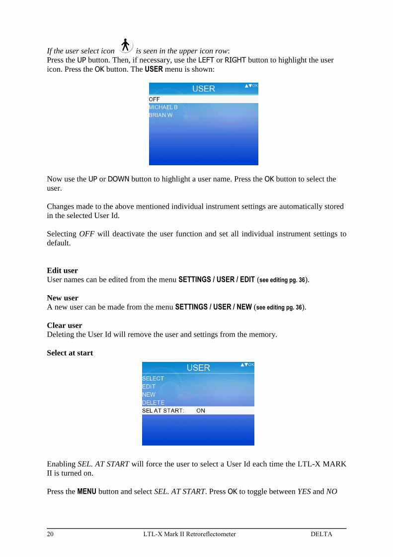
If the user select icon is seen in the upper icon row:
Press the UP button. Then, if necessary, use the LEFT or RIGHT button to highlight the user
icon. Press the OK button. The USER menu is shown:
Now use the UP or DOWN button to highlight a user name. Press the OK button to select the
user.
Changes made to the above mentioned individual instrument settings are automatically stored
in the selected User Id.
Selecting OFF will deactivate the user function and set all individual instrument settings to
default.
Edit user
User names can be edited from the menu SETTINGS / USER / EDIT (see editing pg. 36).
New user
A new user can be made from the menu SETTINGS / USER / NEW (see editing pg. 36).
Clear user Deleting the User Id will remove the user and settings from the memory.
Select at start
Enabling SEL. AT START will force the user to select a User Id each time the LTL-X MARK
II is turned on.
Press the MENU button and select SEL. AT START. Press OK to toggle between YES and NO
DELTA LTL-X Mark II Retroreflectometer 21
Selecting a road marking icon
The purpose of the road marking icon.
The road marking icons are used as labels for the individual measurement corresponding to
the measured road marking and will be saved in the log together with the measuring result.
The icon will be presented together with the corresponding measurement when viewing the
log, print out or in the RSC program (see pg. 47).
There are 24 fixed icons to select from. Six of the icons can be programmed as individual pre-
sets for each series (see pg. 31) and will be ready for selection when a series is selected.
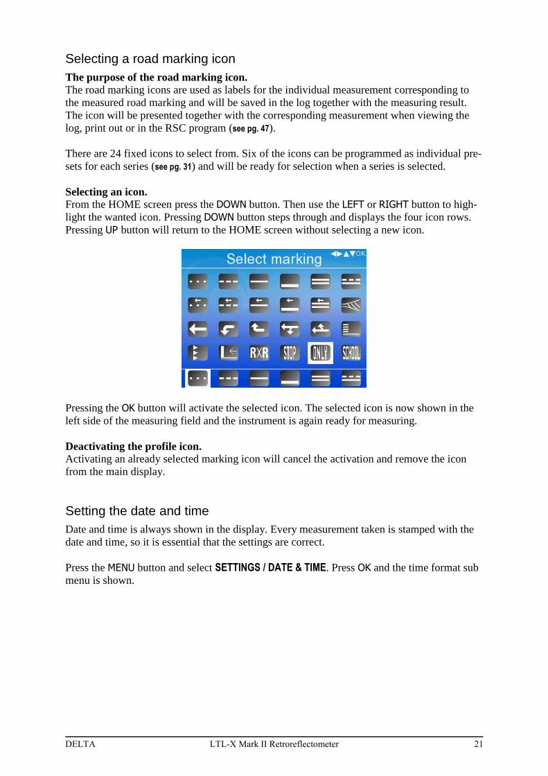
Selecting an icon.
From the HOME screen press the DOWN button. Then use the LEFT or RIGHT button to high-
light the wanted icon. Pressing DOWN button steps through and displays the four icon rows.
Pressing UP button will return to the HOME screen without selecting a new icon.
Pressing the OK button will activate the selected icon. The selected icon is now shown in the
left side of the measuring field and the instrument is again ready for measuring.
Deactivating the profile icon.
Activating an already selected marking icon will cancel the activation and remove the icon
from the main display.
Setting the date and time
Date and time is always shown in the display. Every measurement taken is stamped with the
date and time, so it is essential that the settings are correct.
Press the MENU button and select SETTINGS / DATE & TIME. Press OK and the time format sub
menu is shown.

22 LTL-X Mark II Retroreflectometer DELTA
Setting the time format
Press OK when TIME FORMAT is highlighted and toggle between 12 and 24 hr format by
pushing the OK button.
Setting the date format
Navigate to DATE FORMAT and press OK.
Highlight the preferred date format using UP or DOWN. Press OK to accept.
Adjusting the time and date
Press OK when SET TIME/DATE is highlighted.
Press OK to activate each line and use UP or DOWN to set the figure. Press OK to accept the
setting.
Note: the time in this menu is not live updated, but it will synchronize the time shown in the
HOME screen.
DELTA LTL-X Mark II Retroreflectometer 23
Setting the Time zone
Press OK when TIMEZONE is highlighted. Press OK to open the list of geographical loca-
tions. Choose your area. Press OK to select. Now a new list shows up with national time
zones. Scroll to your location and press OK to select.
Time zone is used in relation with automatic daylight saving and When SYNC. TO GPS is en-
abled.
Note:
Synchronize to GPS
When SYNC. TO GPS is highlighted press OK to toggle between ON and OFF. By activating
this function make sure that the time zone is correct otherwise the clock in the LTL-X Mark II
and the time stamp in the log data will probably not be correct.
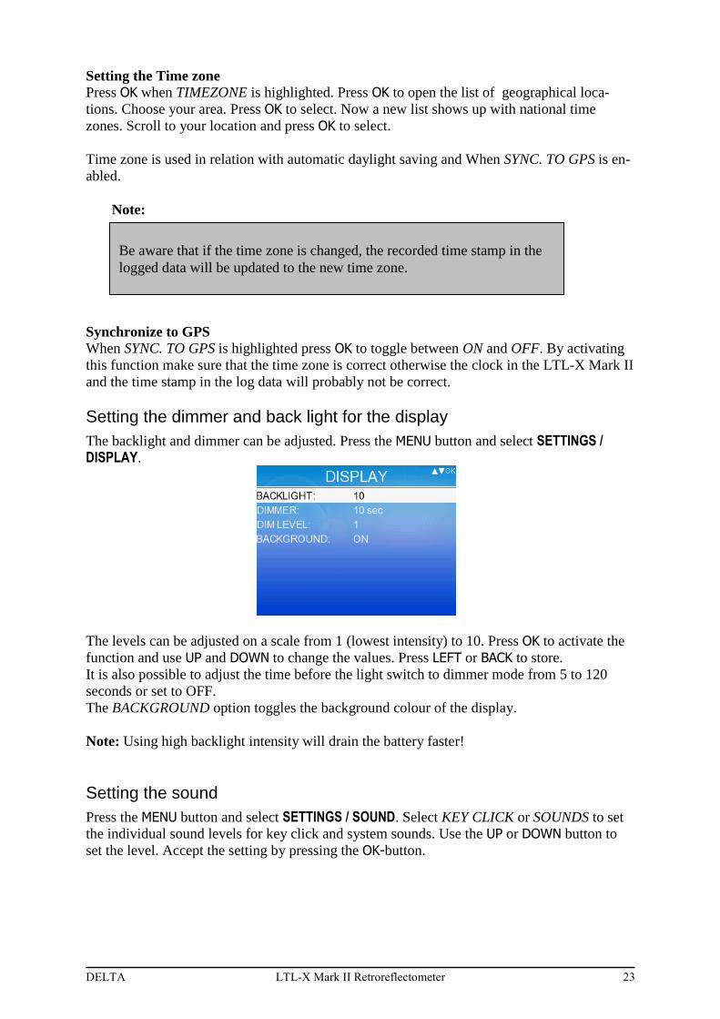
Setting the dimmer and back light for the display
The backlight and dimmer can be adjusted. Press the MENU button and select SETTINGS / DISPLAY.
The levels can be adjusted on a scale from 1 (lowest intensity) to 10. Press OK to activate the
function and use UP and DOWN to change the values. Press LEFT or BACK to store.
It is also possible to adjust the time before the light switch to dimmer mode from 5 to 120
seconds or set to OFF.
The BACKGROUND option toggles the background colour of the display.
Note: Using high backlight intensity will drain the battery faster!
Setting the sound
Press the MENU button and select SETTINGS / SOUND. Select KEY CLICK or SOUNDS to set
the individual sound levels for key click and system sounds. Use the UP or DOWN button to
set the level. Accept the setting by pressing the OK-button.
Be aware that if the time zone is changed, the recorded time stamp in the
logged data will be updated to the new time zone.
24 LTL-X Mark II Retroreflectometer DELTA
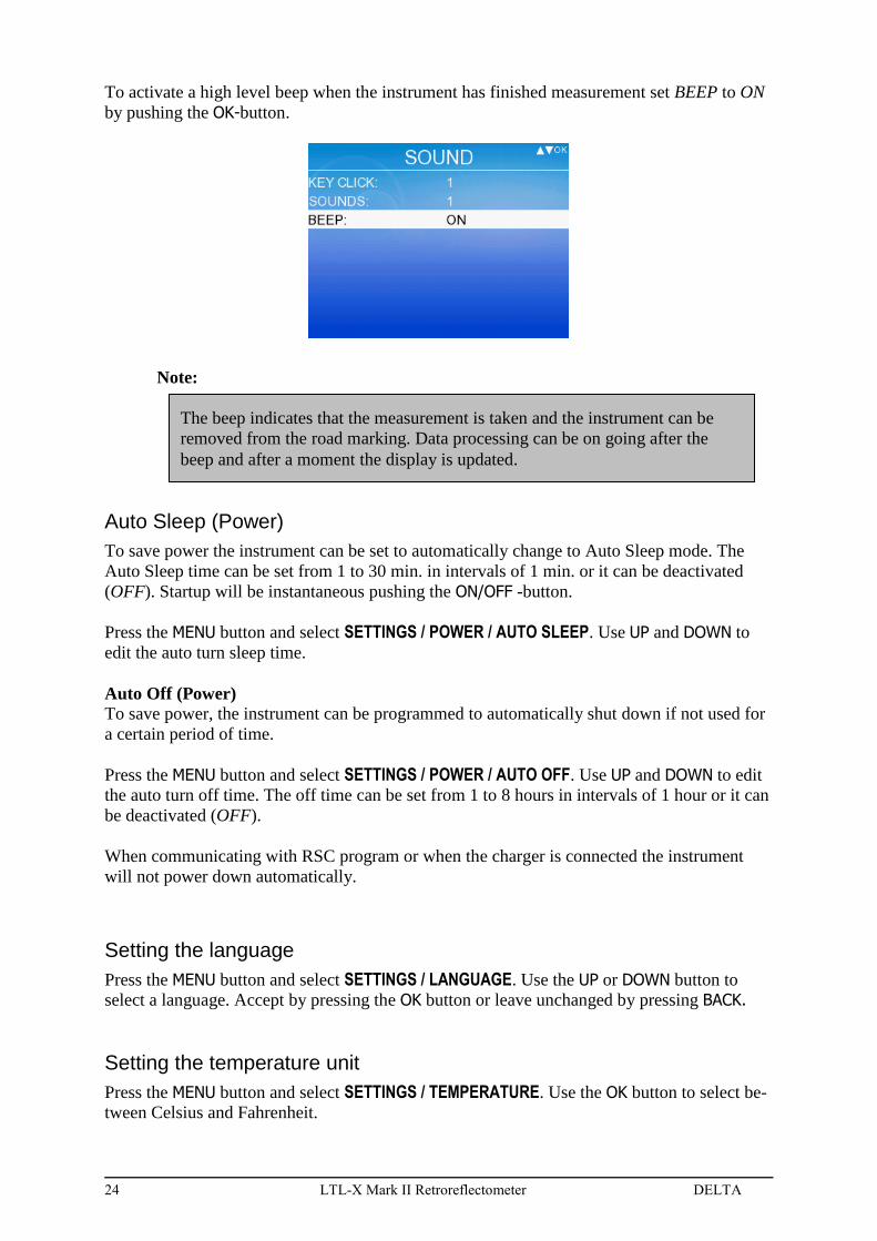
To activate a high level beep when the instrument has finished measurement set BEEP to ON
by pushing the OK-button.
Note:
Auto Sleep (Power)
To save power the instrument can be set to automatically change to Auto Sleep mode. The
Auto Sleep time can be set from 1 to 30 min. in intervals of 1 min. or it can be deactivated
(OFF). Startup will be instantaneous pushing the ON/OFF -button.
Press the MENU button and select SETTINGS / POWER / AUTO SLEEP. Use UP and DOWN to
edit the auto turn sleep time.
Auto Off (Power)
To save power, the instrument can be programmed to automatically shut down if not used for
a certain period of time.
Press the MENU button and select SETTINGS / POWER / AUTO OFF. Use UP and DOWN to edit
the auto turn off time. The off time can be set from 1 to 8 hours in intervals of 1 hour or it can
be deactivated (OFF).
When communicating with RSC program or when the charger is connected the instrument
will not power down automatically.
Setting the language
Press the MENU button and select SETTINGS / LANGUAGE. Use the UP or DOWN button to
select a language. Accept by pressing the OK button or leave unchanged by pressing BACK.
Setting the temperature unit
Press the MENU button and select SETTINGS / TEMPERATURE. Use the OK button to select be-
tween Celsius and Fahrenheit.
The beep indicates that the measurement is taken and the instrument can be
removed from the road marking. Data processing can be on going after the
beep and after a moment the display is updated.

DELTA LTL-X Mark II Retroreflectometer 25
Setting the SMART key function
This button is user programmable to one of several functions, e.g. to clear the last meas-
urement. Press the MENU button and select SETTINGS / SMART.
Use the UP or DOWN button to select the SMART KEY function. Accept by pressing the
OK button.
The selected function is now accessed every time is pressed
Setting the AUX functions / GPS
The AUX function is used to enable auxiliary built-in equipment like the GPS.
Using GPS The GPS receiver is mounted inside the instrument. The GPS system is used to log position
data (latitude and longitude) together with the measurement data.
If activated a GPS icon is shown in the upper icon row
The icon will display the quality (reliability) of the GPS signal.

26 LTL-X Mark II Retroreflectometer DELTA
Below is an explanation of the GPS icon states.
GOOD: The GPS HDOP (Horizontal Dilution Of Precision) value is below 5.
FAIR: The GPS HDOP value is larger than 5, but the GPS can FIX.
NO: The GPS cannot FIX (weak or no signal).
The GPS position data, HDOP value, and the number of satellites used in the position calcula-
tion are saved in the log together with the RL data.
Activating the GPS
Press the MENU button and select SETTINGS / AUX, highlight the GPS line and press the OK
button to toggle the GPS ON or OFF. Press the BACK button or the HOME button to return to
the HOME screen.
The GPS data can be viewed from the HOME screen by pressing the UP button and then high-
lighting the GPS icon by using LEFT or RIGHT buttons. Press the OK button to display the
GPS data. When the GPS data changes the display is updated.
If the GPS does not fix and a measurement is taken a warning menu appears. You will be pre-
sented with the following option:
No GPS fix. Measure anyway: NO / YES?
More about the GPS
The GPS unit will typically acquire satellite signals and process a position fix in 1-15 seconds
after the LTL-X Mark II is turned on. If the GPS receiver has been turned off for a long peri-
od of time or the instrument has been moved far away for its last position, the time to first fix
will take longer.
LTL-X Mark II will log following GPS information’s:
LATITUDE, LONGITUDE, UTC TIME, HDOP, NUMBER OF SATELLITES USED,
POSITION FIX FLAGS AND DATUM.
“Position Fix Flags” is interpreted by the LTL-X Mark II software and the information’s are
shown in plain text in the View log see pg. 32.
Datum is by default set to: WGS84 and can’t be changed.
Latitude and Longitude are output in the format:
Degrees, Minutes and (Decimal) Fractions of Minutes.
The GPS engine used has a navigation performance of 2.5 m CEP1)
The precision of the GPS receiver is determined by many factors. A few are listed below:
Signal obstruction. The GPS receiver requires a clear view of the sky. Trees, build-
ings and other environmental objects may affect the satellite signals.
Satellite constellation and geometry.
Multi path (reflection of signal from buildings etc.).

DELTA LTL-X Mark II Retroreflectometer 27
The HDOP (Horizontal Dilution of Precision) is a number that indicates the quality and preci-
sion of the received GPS data (low values are better than high).
A HDOP value <1 indicates a high precision position. HDOP signals between 1 and 5 indi-
cates an fair precision and DHOP values >5 a poor precision
When the GPS is used, the operating time for the LTL-X Mark II will be decreased and you
may have to charge the battery more often.
1) CEP (Circular Error Probable):
A statistical measure of the horizontal precision. The CEP value is defined as a circle's radius, when
centered at the true position, encloses 50% of the data points in a horizontal scatter plot. Thus, half the
data points are within a 2-D CEP circle and half are outside the circle.
Setup (basic / advanced)
Setup is used to separate between basic and advanced users. The basic settings reduce the
number of menus available to the user. For example, in basic menu operation, users cannot
clear the log.
The following menu points can be selected in basic mode:
Settings: User, Date & Time, Display, Sound and Temperature, Setup
Measurement type: RL, Wet timer, Timer alarm
Log: View log
Diagnosis: Instrument, Battery, Boards, GPS, System
Help: All menus available
Auto Print
ADVANCED setting will provide access to all menu functions.
To change the setup, press MENU and select SETTINGS / SETUP. Pressing OK will toggle be-
tween ADVANCED and BASIC. To return from setup press BACK or HOME.
28 LTL-X Mark II Retroreflectometer DELTA
MEASURE TYPE
When taking wet or rain simulation measurements some procedures describe to wait a certain
amount of time from the marking is made wet and to the measurement is taken. The WET
TIMER assists the operator to time this kind of measurements.
Depending on the “wetting” method it can be necessary to mount wet night rails. See pg. 44.
Wet timer
The wet timer can be adjusted between 15 and 60 seconds. The wet timer automatically car-
ries out the measurement or sound an alarm after the set period of time.
Timer Alarm
Toggle between “Measure” or “Alarm”. The selected option is used when wet timer times out.
DELTA LTL-X Mark II Retroreflectometer 29
SERIES ID
Working with Series Id
The purpose of a Series Id
The Series Id is a label, for example the name of a road. Although measurements can be per-
formed without selecting a Series Id, it is convenient to group (name) the measurements for
each geographical spot, road or part of a road for easier recognition. The Series Id for such a
group of measurements will be saved in the log together with the measuring results. The Id
must be selected prior to the measurement.
The individual measurements in a group can further be labeled by selecting a road marking
icon (see pg. 31) corresponding to the actual road.
The instrument can store unlimited Series Id’s.
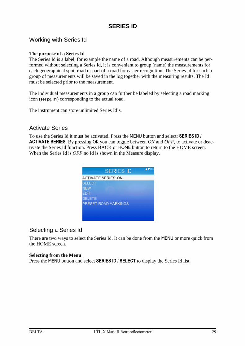
Activate Series
To use the Series Id it must be activated. Press the MENU button and select: SERIES ID / ACTIVATE SERIES. By pressing OK you can toggle between ON and OFF, to activate or deac-
tivate the Series Id function. Press BACK or HOME button to return to the HOME screen.
When the Series Id is OFF no Id is shown in the Measure display.
Selecting a Series Id
There are two ways to select the Series Id. It can be done from the MENU or more quick from
the HOME screen.
Selecting from the Menu
Press the MENU button and select SERIES ID / SELECT to display the Series Id list.
30 LTL-X Mark II Retroreflectometer DELTA
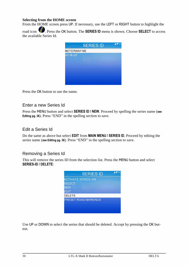
Selecting from the HOME screen
From the HOME screen press UP. If necessary, use the LEFT or RIGHT button to highlight the
road icon . Press the OK button. The SERIES ID menu is shown. Choose SELECT to access
the available Series Id.
Press the OK button to use the name.
Enter a new Series Id
Press the MENU button and select SERIES ID / NEW. Proceed by spelling the series name (see
Editing pg. 36). Press “END” in the spelling section to save.
Edit a Series Id
Do the same as above but select EDIT from MAIN MENU / SERIES ID. Proceed by editing the
series name (see Editing pg. 36). Press “END” in the spelling section to save.
Removing a Series Id
This will remove the series ID from the selection list. Press the MENU button and select
SERIES-ID / DELETE:
Use UP or DOWN to select the series that should be deleted. Accept by pressing the OK but-
ton.
DELTA LTL-X Mark II Retroreflectometer 31
A confirmation menu is shown:
Note! All measurements in the selected series will be erased from the log!
If a large numbers of Series Id’s are to be deleted this can more easily be done from the
RSC program from the project tab click .
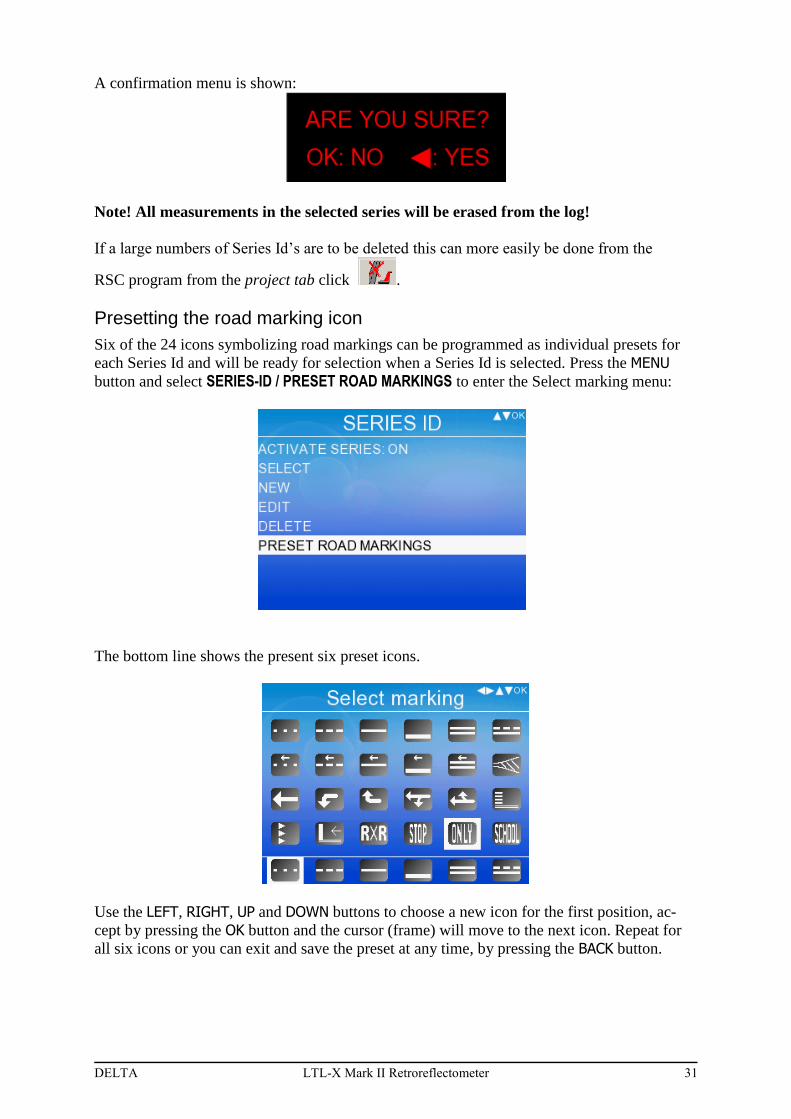
Presetting the road marking icon
Six of the 24 icons symbolizing road markings can be programmed as individual presets for
each Series Id and will be ready for selection when a Series Id is selected. Press the MENU
button and select SERIES-ID / PRESET ROAD MARKINGS to enter the Select marking menu:
The bottom line shows the present six preset icons.
Use the LEFT, RIGHT, UP and DOWN buttons to choose a new icon for the first position, ac-
cept by pressing the OK button and the cursor (frame) will move to the next icon. Repeat for
all six icons or you can exit and save the preset at any time, by pressing the BACK button.

32 LTL-X Mark II Retroreflectometer DELTA
THE LOG
Each time a measurement is taken data is stored in the log. The following data, among others,
are saved, if enabled:
Measurement result incl. average
Date and time.
Name of measuring series (Series ID) and sequence number.
Road marking icon
User name (User ID)
GPS data
Instrument status
Temperature & humidity
The instrument can store >200.000 measurements in the log.
Clearing data in the log
Press the MENU button and select LOG / CLEAR DATA:
This menu gives the option to clear:
the last measurement,
all measurements
one of the measuring series
stored in the log.
By pressing the OK button you will be asked to confirm the erasure of the data. By pressing
LEFT data will be cleared. By pressing OK they will not be cleared.
DELTA LTL-X Mark II Retroreflectometer 33
If you selected SERIES, you must choose the series you wish to delete from the list shown.
Only the log entries will be erased. The series will still be available in the series select list.
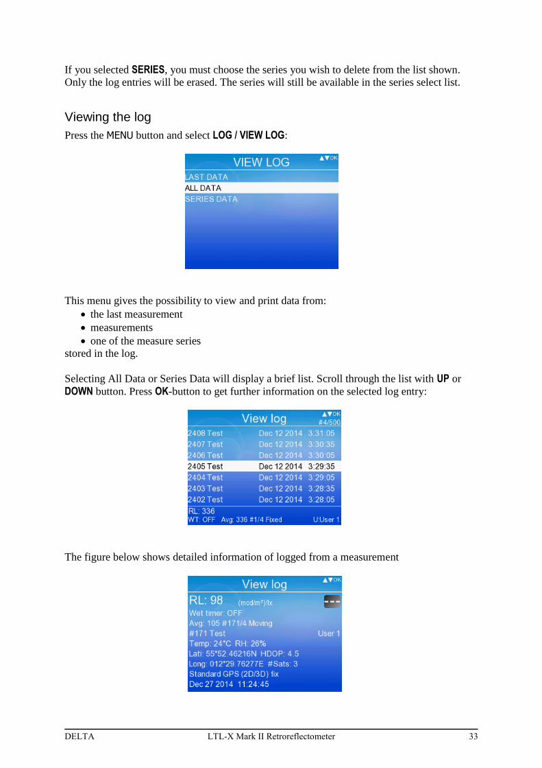
Viewing the log
Press the MENU button and select LOG / VIEW LOG:
This menu gives the possibility to view and print data from:
the last measurement
measurements
one of the measure series
stored in the log.
Selecting All Data or Series Data will display a brief list. Scroll through the list with UP or
DOWN button. Press OK-button to get further information on the selected log entry:
The figure below shows detailed information of logged from a measurement

34 LTL-X Mark II Retroreflectometer DELTA
In the first line, the menu shows the RL value, thereafter in the following lines other key
measurement data. To view a list of the individual errors/warnings in the status, print out the
measurement (see below).
Press the PRINT button to print the log from the highlighted measurement. Any warning or
errors detected during the measurement will be shown in the print out.
To return to the log menu, press BACK
View series data.
In the LOG MENU, select SERIES DATA to view the list of series.
The menu shows a Series ID in each line. Pressing DOWN or UP, will scroll through the series
list. Highlight a series and press the OK button to view the individual measurements.
Highlight a measurement in the individual display and press the PRINT button to print out the
measurement.
To return press the BACK button.
The LTL-X Mark II log and display will be able to show the most recent 500 measurement
taken, additional measurements will still be kept in the log and can be viewed when trans-
ferred to a PC.
The LTL-X Mark II log is not intended for data storage. Even if the log may store up to
200.000 measurements an increasing number of logged measurements will gradually slow
down the performance of the LTL-X Mark II. If a slowdown is seen make a transfer of data to
reduce or empty the log.
DELTA LTL-X Mark II Retroreflectometer 35
OTHER SETTINGS
Average function
An average function can be activated showing the average of the measured RL value calculat-
ed over a selectable number of measurements (N = 2 to 99). The average mode can be fixed
or moving. In moving mode the average is always calculated from the last N measurements
where N is the selected number of measurements. In fixed mode the averaging will start over
again when N measurements have been taken. The average data is shown in the HOME
screen at the lower right corner.
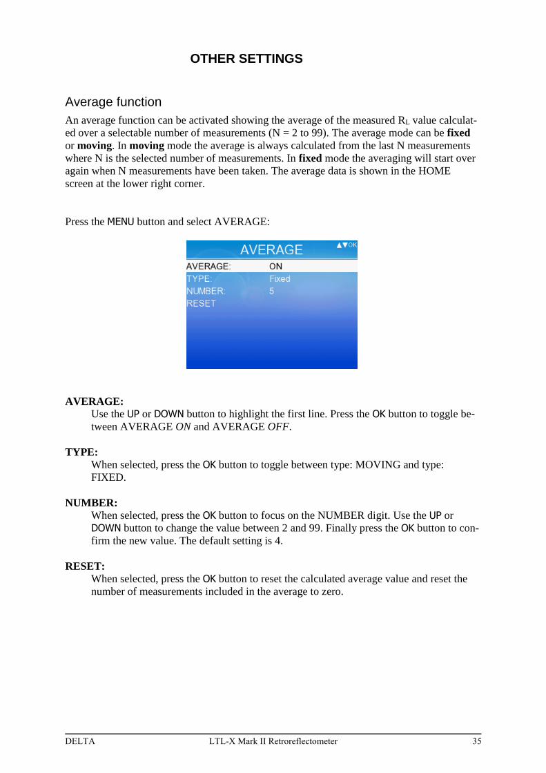
Press the MENU button and select AVERAGE:
AVERAGE:
Use the UP or DOWN button to highlight the first line. Press the OK button to toggle be-
tween AVERAGE ON and AVERAGE OFF.
TYPE:
When selected, press the OK button to toggle between type: MOVING and type:
FIXED.
NUMBER:
When selected, press the OK button to focus on the NUMBER digit. Use the UP or
DOWN button to change the value between 2 and 99. Finally press the OK button to con-
firm the new value. The default setting is 4.
RESET:
When selected, press the OK button to reset the calculated average value and reset the
number of measurements included in the average to zero.
36 LTL-X Mark II Retroreflectometer DELTA
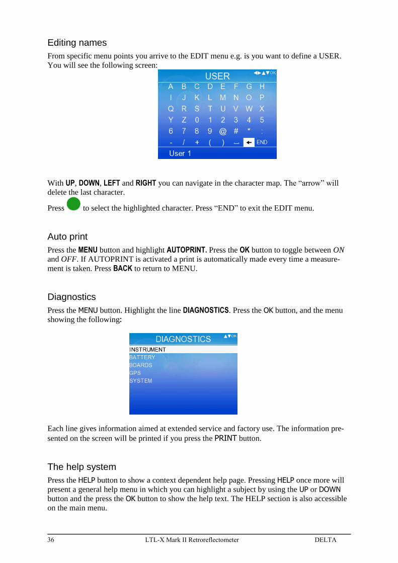
Editing names
From specific menu points you arrive to the EDIT menu e.g. is you want to define a USER.
You will see the following screen:
With UP, DOWN, LEFT and RIGHT you can navigate in the character map. The “arrow” will
delete the last character.
Press to select the highlighted character. Press “END” to exit the EDIT menu.
Auto print
Press the MENU button and highlight AUTOPRINT. Press the OK button to toggle between ON
and OFF. If AUTOPRINT is activated a print is automatically made every time a measure-
ment is taken. Press BACK to return to MENU.
Diagnostics
Press the MENU button. Highlight the line DIAGNOSTICS. Press the OK button, and the menu
showing the following:
Each line gives information aimed at extended service and factory use. The information pre-
sented on the screen will be printed if you press the PRINT button.
The help system
Press the HELP button to show a context dependent help page. Pressing HELP once more will
present a general help menu in which you can highlight a subject by using the UP or DOWN
button and the press the OK button to show the help text. The HELP section is also accessible
on the main menu.
DELTA LTL-X Mark II Retroreflectometer 37
SECTION 4
MAINTENANCE
General care
The retroreflectometer is constructed for outdoor use in ordinary good weather conditions. It
will stand moist weather with wet roads, but caution must be taken against heavy rain and
dirt. The LTL-X Mark II retroreflectometer is an optical instrument and shall be handled as
such. Avoid shock and vibration if possible.
Protection window
The protection window is accessible from underneath of the instrument. The protection win-
dow is coated with a high-efficiency anti-reflection coating. Take care not to damage this
coating when cleaning. Compressed air or a fine brush can be used for removing loose parti-
cles/dust. If this is not sufficient the window should by cleaned using a soft paper tissue or
cloth and some window cleaning liquid.
MAKE SURE THE PROTECTION WINDOW IS CLEAN AND UNDAMAGED AT ANY
TIME TO ENSURE CORRECT MEASUREMENT RESULTS
Battery
The LTL-X Mark II retroreflectometer is powered by a high capacity 12V/4.5Ah NiMH
(Nickel-Metal Hydride) battery. Under normal use, this battery requires no maintenance.
However it is recommended to keep the battery fully charged. A fully charged battery is more
capable of withstanding degeneration.
A mains powered 15V power adaptor for charging (the instrument has a built-in charging cir-
cuit) is supplied as customary delivery. If the instrument was turned off it will automatically
power on when the power adaptor is connected. The battery icon in the upper right corner will
also indicate the charging state. Charging time will be 3½ hours and a new and fully charged
battery will provide approx. 2.500 measurements.
No harm done if leaving the power adaptor connected after the charging process has finished.
However, the instrument must be disconnected from the power adaptor if disconnecting the
battery from the instrument. In addition, the battery can be charged using any DC supply from
15-18 VDC.
For “field” charging the 15V power supply could be powered from an “AC power inverter”
connected to the car battery.
When storing the instrument for a long period of time fully charge the battery.
THE BATTERY SUPPLIED WITH LTL-X Mark II IS SPECIALLY DESIGNED FOR THE
INSTRUMENT TO ENSURE SAFE USE. IF A NON DELTA SUPPLIED OR APPROVED
BATTERY IS USED, DELTA CAN TAKE NO RESPONSIBILITY FOR ANY DAMAGES
CAUSED DUE TO THE PERFORMANCE OF THIS BATTERY.
38 LTL-X Mark II Retroreflectometer DELTA
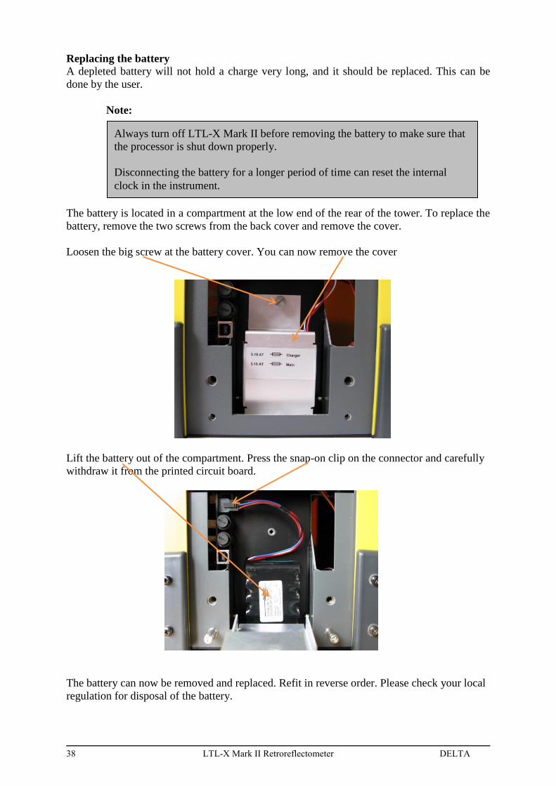
Replacing the battery
A depleted battery will not hold a charge very long, and it should be replaced. This can be
done by the user.
Note:
The battery is located in a compartment at the low end of the rear of the tower. To replace the
battery, remove the two screws from the back cover and remove the cover.
Loosen the big screw at the battery cover. You can now remove the cover
Lift the battery out of the compartment. Press the snap-on clip on the connector and carefully
withdraw it from the printed circuit board.
The battery can now be removed and replaced. Refit in reverse order. Please check your local
regulation for disposal of the battery.
Always turn off LTL-X Mark II before removing the battery to make sure that
the processor is shut down properly.
Disconnecting the battery for a longer period of time can reset the internal
clock in the instrument.
DELTA LTL-X Mark II Retroreflectometer 39
Battery status
An indication of the capacity of the battery can be seen from the icon, in the upper icon row.
Shows that charging takes place
Shows that the charging is finished
Indicates that the battery is fully charged
Indicates that the capacity of the battery is half empty
The battery is almost empty and need recharging
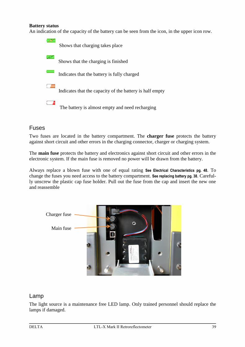
Fuses
Two fuses are located in the battery compartment. The charger fuse protects the battery
against short circuit and other errors in the charging connector, charger or charging system.
The main fuse protects the battery and electronics against short circuit and other errors in the
electronic system. If the main fuse is removed no power will be drawn from the battery.
Always replace a blown fuse with one of equal rating See Electrical Characteristics pg. 48. To
change the fuses you need access to the battery compartment. See replacing battery pg. 38. Careful-
ly unscrew the plastic cap fuse holder. Pull out the fuse from the cap and insert the new one
and reassemble
Lamp
The light source is a maintenance free LED lamp. Only trained personnel should replace the
lamps if damaged.
Charger fuse
Main fuse

40 LTL-X Mark II Retroreflectometer DELTA
Calibration
The instrument is delivered with two calibration units.
the RED field calibration unit, for calibration of the instrument at regular intervals.
This unit should be kept together with the LTL-X Mark II.
the BLACK reference calibration unit, for verification of the (red) field calibration
unit. This unit should be kept away in a safe place, and is only needed when the field
calibration unit has to be checked.
The LTL-X Mark II is factory calibrated and very stable. Anyway, during daily use it is rec-
ommended that the operator calibrate the instrument, with the RED field calibration unit, at
suitable intervals e.g. before starting a new series of measurements. This procedure is called
calibration.
The daily use of the calibration unit can affect the accuracy of the calibration value due to
dirt, scratches etc. Therefore, at appropriate intervals, the RED field calibration unit must be
verified against the BLACK reference calibration unit. This procedure is called verifica-
tion.
The BLACK reference calibration unit is factory calibrated and traceable to the International
calibration institutes PTB and NIST.
The reference
Calibration procedure
To calibrate the LTL-X Mark II carry out the following steps using the RED field calibration
unit:
Before mounting the calibration unit note the RL value written on label on the calibra-
tion unit.
Place the instrument upon the calibration unit. It is done by tilting the instrument
slightly backward, and then mount the unit underneath the front end of the instrument.

DELTA LTL-X Mark II Retroreflectometer 41
Make sure that the pins on the side of the unit fit into the slots in the LTL-X structure.
It is important that the calibration unit faces with the white ceramic towards the in-
strument tower.
Press the CALIBRATION button . Select CALIBRATE RL and press OK-button.
Check the value displayed and, if necessary, adjust it using the DOWN or UP buttons
so it match the value stamped on the calibration unit.
Press the OK-button to calibrate.
When calibration is finished, press HOME.
The calibration procedure is now completed. Before removing the calibration unit, check the
calibration by taking a regular measurement on the calibration unit. The measured value
should preferably match the value stamped on the calibration unit ( ± 2-3 unit deviation is ac-
ceptable). Remove the calibration unit and store it properly.
42 LTL-X Mark II Retroreflectometer DELTA
Verification procedure
At appropriate intervals the value on the RED field calibration unit must be verified, or if
necessary updated. The procedure to do this is:
Do a calibration on the BLACK reference calibration unit. Follow the instructions in
the calibration procedure above.
Following take 2-3 measurement on the RED field calibration unit. If the average RL
value on the RED field calibration unit differs from the measured value, shown in the
display, update the label on the RED field calibration unit with the new average RL
value.
The verification is now done and the RED field calibration unit is “recalibrated”.
Keep the calibration ceramic in good condition!
To make sure that calibration of the retroreflectometer is correct, it is important that the ce-
ramic on the calibration units is clean and undamaged. Always keep the calibration units well
protected.
If the ceramic on a calibration unit is stained, scratched or broken, the calibration unit has to
be repaired and recalibrated or changed to a new one. In case of dust on the ceramics surface,
the use of clean compressed air is recommended for removal. The use of a soft damp cloth is
recommended if compressed air fails to remove the dirt. If necessary, use a mild household
detergent.
Calibration service
To ensure reliable measurements, it is recommended that the BLACK reference calibration
unit periodically is recalibrated to a traceable standard or replace by purchasing a new ceram-
ic reference block.
DELTA offers calibration traceable to PTB (Physikalsich-Technische Bundesanstalt, Germa-
ny) and NIST (National Institute of Standards and Technology, USA).
For information about service please contact your DELTA distributor or DELTA directly. At
DELTA you can forward your request via our web-site www.roadsensors.com or send a mail
directly to: [email protected].
Always store the calibration unit in a dry, dust free and clean environment.
If stained, scratched or broken it must be replaced.

DELTA LTL-X Mark II Retroreflectometer 43
Printer
The printer is located at the back of the tower. The printer is a high-speed high quality mini
thermal printer. It has only a few moving parts and does not require any special or periodic
maintenance.
The printer uses a thermal paper roll, width: 57.5±0.5 mm (2.26 in), diameter: max. 31 mm
(1.22 in)
Replacing paper
Replacing the paper is simple. First, pull the little lever out with your finger and the cover will
open into the paper roll compartment.
Insert the new paper roll and let a short paper tail hanging out at the top. Close the cover with
a firm push and with some of the paper sticking out.
44 LTL-X Mark II Retroreflectometer DELTA
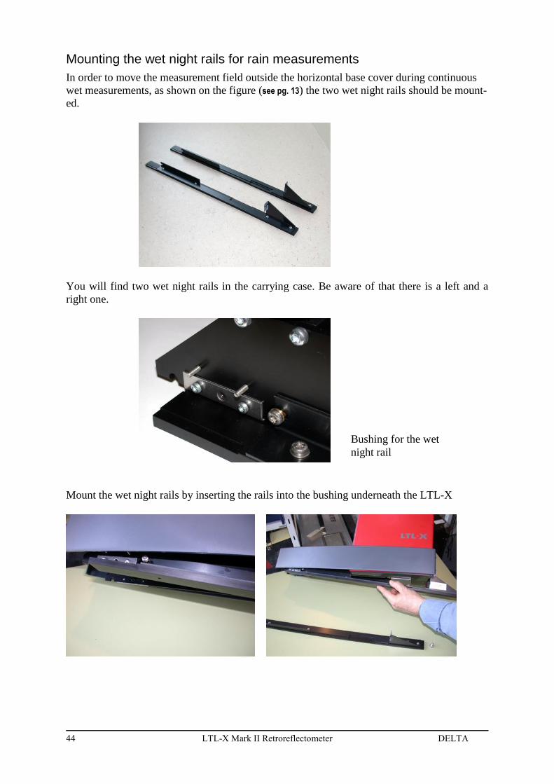
Mounting the wet night rails for rain measurements
In order to move the measurement field outside the horizontal base cover during continuous
wet measurements, as shown on the figure (see pg. 13) the two wet night rails should be mount-
ed.
You will find two wet night rails in the carrying case. Be aware of that there is a left and a
right one.
Mount the wet night rails by inserting the rails into the bushing underneath the LTL-X
Bushing for the wet
night rail

DELTA LTL-X Mark II Retroreflectometer 45
Fasten the wet night rails in the rear plate with the screws delivered (M6*16 mm) with the
rails. Make sure that the LTL-X is resting on the rails before lightening the screws.
The wet night rails are now ready for use. After use dismount the wet night rails by reversing
above operations.

46 LTL-X Mark II Retroreflectometer DELTA
Mounting the wheel unit
A wheel unit can be mounted in the rear of the instrument for easy transportation during
heavy use.
Nuts for fasten the wheels
The wheels are mounted easily to the
rear by fastening the two nuts mount-
ed on the wheel block.
DELTA LTL-X Mark II Retroreflectometer 47
APPENDIX A
COMMUNICATION FACILITIES
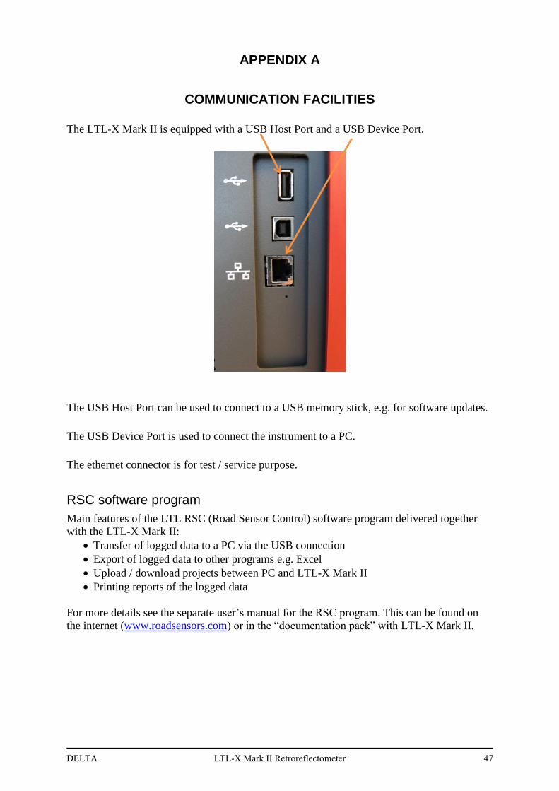
The LTL-X Mark II is equipped with a USB Host Port and a USB Device Port.
The USB Host Port can be used to connect to a USB memory stick, e.g. for software updates.
The USB Device Port is used to connect the instrument to a PC.
The ethernet connector is for test / service purpose.
RSC software program
Main features of the LTL RSC (Road Sensor Control) software program delivered together
with the LTL-X Mark II:
Transfer of logged data to a PC via the USB connection
Export of logged data to other programs e.g. Excel
Upload / download projects between PC and LTL-X Mark II
Printing reports of the logged data
For more details see the separate user’s manual for the RSC program. This can be found on
the internet (www.roadsensors.com) or in the “documentation pack” with LTL-X Mark II.

48 LTL-X Mark II Retroreflectometer DELTA
APPENDIX B
SPECIFICATION
General characteristics
Illumination angle ............................................................................................................ 1.24º
Observation angle ............................................................................................................ 2.29º
Equivalent observer distance ........................................................................................... 30 m
Observation angular spread .......................................................................................... ±0.17º
Type 30m CEN
Illumination angular spread horizontal ........................................................................ 0.33º
Illumination angular spread vertical ............................................................................ 0.17º
Field of measurement:
Width ....................................................................................................... 45 mm (1.77 inch)
Length (typ.) .......................................................................................... 200 mm (7.87 inch)
RL range (mcd·m-2·lx-1) ................................................................................................ 0-2000
Radio: ........................................................................................... EN 300440-1 V1.6.1:2010
EMC: ............................................... EN 301489-1 V1.8.1:2008, EN 301489-3 V1.4.1:2002
Safety: ....................................................... EN/IEC 60950-1 :2006, EN/IEC 60950-22 :2006
FCC: .................................................................................. 47 CFR, FCC Part 15B, Class A
Power supply:
Battery ................................................................................. Built in 12 volt / 4,5 Ah NiMH
External charger power supply .................... Friwo FW7530/15 (100-240 VAC / 15VDC )
Charging time ................................................................................... Approx.3 hour 30 min
Charger fuse (5*20 mm) .......................................................................................... T3.15A
Power supply fuse (5*20 mm) ................................................................................. T3.15A
Data memory .................................................................................... >200.000 measurements
Data transfer ................................................................................................................ USB 2.0
DELTA LTL-X Mark II Retroreflectometer 49
Environmental characteristics
Temperature:
Operating .............................................................................. 0ºC to + 45ºC (32ºF to +113º F)
Storage*) ............................................................................. -15ºC to + 55ºC (5º F to +131º F)
Humidity ......................................................................................... 85% and non-condensing
*) Battery must be fully charged
Mechanical characteristics
Max. length ................................................................................................... 573 mm / 22.6 in
Max. width ...................................................................................................... 222 mm / 8.7 in
Max. height ................................................................................................... 538 mm / 21.2 in
Weight of base unit .......................................................................................... 9.7 kg / 21.4lbs
Construction:
Structural parts .................................................................................................... Aluminum
Housing .................................................................................................................. Polymer
Keyboard ...................................................................................................... Silicone rubber
Circuit boards .................................................................................................... Epoxy glass
Printer:
Thermal paper ......................................width/dia. 57.5 ±0.5 mm / 31mm (2.26 in / 1.22in)
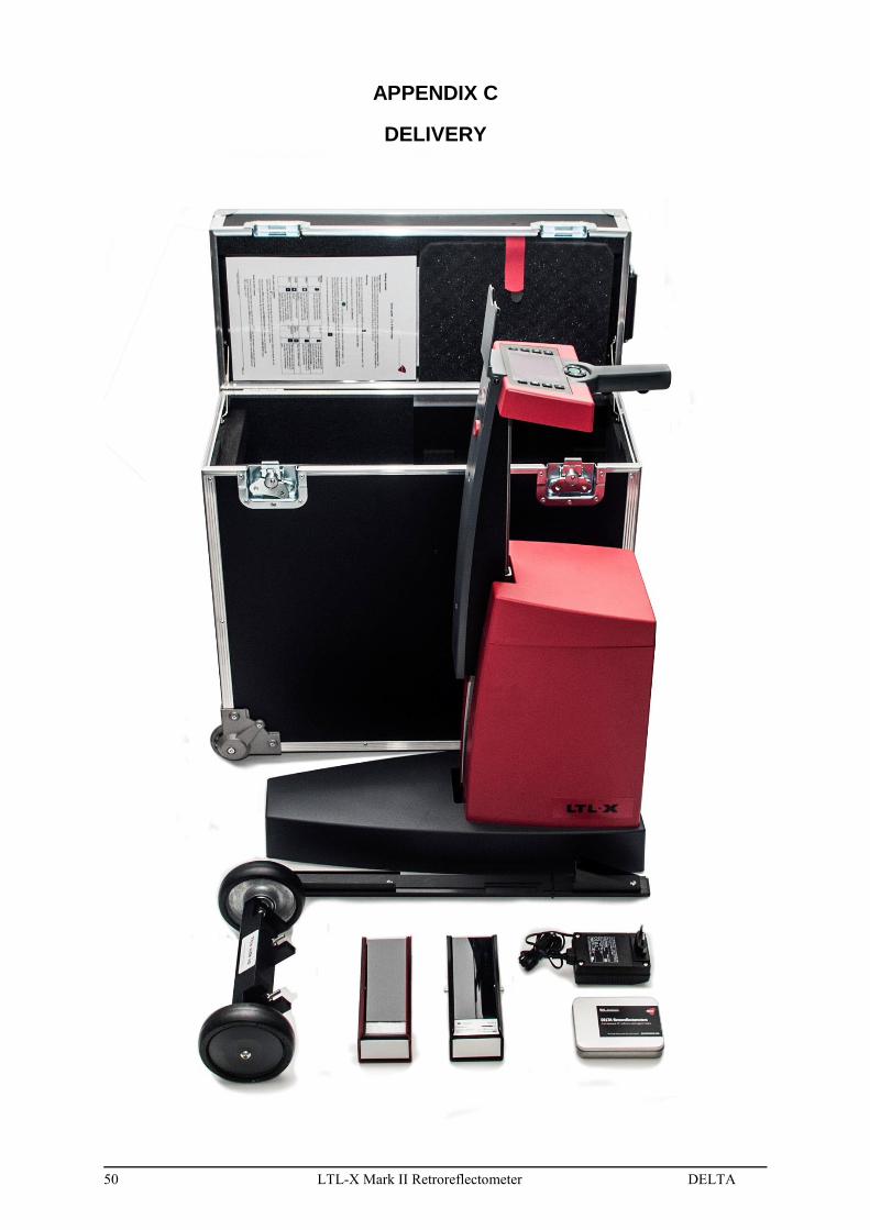
50 LTL-X Mark II Retroreflectometer DELTA
APPENDIX C
DELIVERY