Embed Size (px)
Citation preview

An Introduction to LTE LTE101
Student Guide

P a g e | 2 L T E O v e r v i e w
© Motorola, Inc. All Rights Reserved LTE101v1.1 - SG

L T E O v e r v i e w P a g e | 3
© Motorola, Inc. All Rights Reserved LTE101v1.0 - SG
Contents Lesson 1: Introduction ............................................................................................................................ 4
Lesson 2: LTE /SAE Defined .................................................................................................................... 7
Lesson 3: LTE Air Interface (E‐UTRAN) ................................................................................................. 23
Lesson 4: Evolved Packet System (EPC and E‐UTRAN) ......................................................................... 39
Lesson 5: LTE Call Processing ................................................................................................................ 61
Glossary of terms .................................................................................................................................. 83
EPS Architecture ................................................................................................................................... 85

P a g e | 4 L T E O v e r v i e w
© Motorola, Inc. All Rights Reserved LTE101v1.1 - SG
Lesson 1: Introduction In this lesson, we will discuss the network elements that comprise the LTE network; the Evolved Universal Terrestrial Radio Access Network (E‐UTRAN) and the Evolved Packet Core (EPC). We will then look at Motorola’s LTE solution.
Goals and Objectives
Goal: Introduce the new air interface and IP Core. Course Objectives
1. Describe the difference between LTE and SAE. 2. List the technology used in the air interface. 3. Describe the LTE channel structure. 4. Explain how the network is organized to efficiently support thousands of users. 5. Explain the functions of the main elements of the Evolved Packet Core and the E‐
UTRAN. 6. Describe Motorola LTE/SAE solution. 7. Explain how users enter the network and place calls.

L T E O v e r v i e w P a g e | 5
© Motorola, Inc. All Rights Reserved LTE101v1.0 - SG
Course Organization
Figure 1
This is a diagram of the course lessons. The course was designed in a hieratical fashion. You should begin at the top with lesson one and lesson two. After lesson two, you may select either the LTE air interface or the SAE‐ Motorola solution lesson. The first path focuses on the Air Interface, and the second focuses on the network core. The final element focuses on how calls are placed using both the LTE air interface and the Motorola infrastructure.

P a g e | 6 L T E O v e r v i e w
© Motorola, Inc. All Rights Reserved LTE101v1.1 - SG

L T E O v e r v i e w P a g e | 7
© Motorola, Inc. All Rights Reserved LTE101v1.0 - SG
Lesson 2: LTE /SAE Defined
Objectives
At the completion of this lesson, you should be able to:
1. Define LTE.
2. Define SAE.
3. List the benefits of LTE Network.
4. List the main characteristics of LTE.
5. List the main characteristics of SAE.
6. Explain how LTE/SAE integrates with other 3GPP radio access technologies.
P a g e | 8 L T E O v e r v i e w
© Motorola, Inc. All Rights Reserved LTE101v1.1 - SG
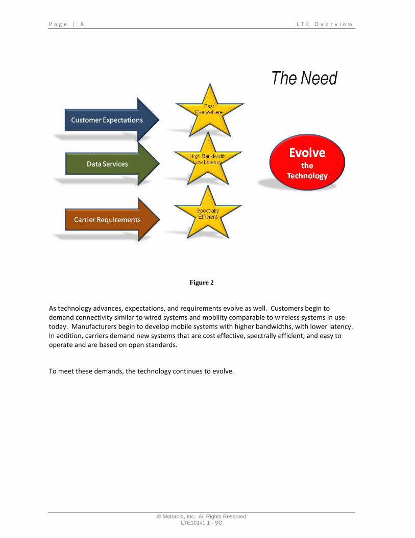
Figure 2
As technology advances, expectations, and requirements evolve as well. Customers begin to demand connectivity similar to wired systems and mobility comparable to wireless systems in use today. Manufacturers begin to develop mobile systems with higher bandwidths, with lower latency. In addition, carriers demand new systems that are cost effective, spectrally efficient, and easy to operate and are based on open standards.
To meet these demands, the technology continues to evolve.

L T E O v e r v i e w P a g e | 9
© Motorola, Inc. All Rights Reserved LTE101v1.0 - SG
Figure 3
The evolution of cellular technology is moving a pace never seen before. Since the 1970’s system performance has continued to improve and adapt as customer demands change, and technology evolves.
Each generation of cellular technology has brought better performance and additional services and features. Starting with simple analog voice services and migrating through digital voice with basic data, to today’s broadband data services.

P a g e | 1 0 L T E O v e r v i e w
© Motorola, Inc. All Rights Reserved LTE101v1.1 - SG
Figure 4
With clear requirements, The as customer demand include advanced services, such as digital voice, real time messaging, on‐demand video services, and the ability to transfer data at high speed.
To cost effectively support these advanced services, the new network has to improve as well. These improvements include supporting higher data throughput, becoming more spectrally efficient, lowering the latency, and building a system that is flexible and scalable to support multiple deployment scenarios.

L T E O v e r v i e w P a g e | 1 1
© Motorola, Inc. All Rights Reserved LTE101v1.0 - SG
Figure 5
With requirements well defined, 3GPP developed standards that were flexible and would meet the needs. 3GPP divided the requirements into two critical areas. The first is the infrastructure and the second is the radio access technology. Together people refer to these standards as the Long Term Evolution, or LTE.

P a g e | 1 2 L T E O v e r v i e w
© Motorola, Inc. All Rights Reserved LTE101v1.1 - SG
Figure 6
Although the technology is commonly referred to as LTE it really is divided into two critical segments, the EPC and the E‐UTRAN.
The first is the core network. The core network has progressed from earlier standards into the Evolved Packet Core, or EPC. The EPC is also commonly referred to as the System Architecture Evolution, or SAE. The evolved packet core specifically defined the core network. This includes, the technologies, protocols, and interfaces used to connect each element together.
The second critical piece of this network is the Radio Access Network. Similar to the EPC, 3GPP continues to develop the Radio Access Network independently from the EPC. The E‐UTRAN defines the access network. It includes details of the air interface, which includes technologies, performance standards, protocols, and procedures used to make the high performance interface between the Users equipment and the fixed infrastructure.
Together, the evolved Packet Core and Evolved UTRAN make up the Evolved Packet System which is commonly referred to as LTE. These standards are first defined in GPP’s release 8.

L T E O v e r v i e w P a g e | 1 3
© Motorola, Inc. All Rights Reserved LTE101v1.0 - SG
Figure 7
Now, let’s define a few of the key performance goals associated with LTE. To start, we need a system that improves the data throughput capabilities compared to current network in use today. LTE’s target is three to four times faster on the downlink and two to three times faster on the uplink compared with that HSPA defined in the release 6 standard.
And the system has to support peak data rates of 100 megabits on the downlink and 50 megabits on the uplink.

P a g e | 1 4 L T E O v e r v i e w
© Motorola, Inc. All Rights Reserved LTE101v1.1 - SG
Figure 8
Latency is another important goal. With the addition of new time critical services and expectation of faster network set‐up time, latency delays are kept to a minimum.
In addition to a faster system with higher data rates, LTE has to support a high number of users per cell. The standard states that cells have to sustain up to 400 users.

L T E O v e r v i e w P a g e | 1 5
© Motorola, Inc. All Rights Reserved LTE101v1.0 - SG
Figure 9
To guarantee that LTE systems can be easily deployed in countless environments, the radio interface has to have the ability to be scaled from 1.25 megahertz up to 20‐megahertz channels. And the LTE standard supports both Frequency division duplexing and Time division duplexing.
As demand on carrier’s allocated bandwidth increases, Spectral efficiency is another key aspect that LTE had to take into account. LTE had to show an improvement in performance compared to release 6 of the GPP standards.

P a g e | 1 6 L T E O v e r v i e w
© Motorola, Inc. All Rights Reserved LTE101v1.1 - SG
Figure 10
Mobility performance is another fundamental goal of LTE. LTE is optimized to support user equipment movement with optimized performance with speeds up to fifteen kilometers per hour and still provide service up to 350 kilometers per hour.

L T E O v e r v i e w P a g e | 1 7
© Motorola, Inc. All Rights Reserved LTE101v1.0 - SG
Figure 11
With these performance goals established, LTE is capable of support a wider range of robust services. These services include Voice over IP, Large‐scale video streaming, Downloading Multimedia, real‐time messaging, large file transfers, Multimedia online gaming, mobile TV, and improve web browsing performance.

P a g e | 1 8 L T E O v e r v i e w
© Motorola, Inc. All Rights Reserved LTE101v1.1 - SG
Figure 12
In addition to performance enhancements, it is equally important to look at possible methods to introduce LTE into the market.
LTE was designed to gracefully interface and compliment other Radio Access Technologies.
With this capability, cellular networks can be planned to migrate to LTE, use LTE as an overlay to existing cellular systems, or coexist with systems currently in use today.

L T E O v e r v i e w P a g e | 1 9
© Motorola, Inc. All Rights Reserved LTE101v1.0 - SG
Figure 13
The 3GPP group built a comprehensive roadmap for other 3GPP RATs. There are migration paths from GSM, UMTS, GPRS, and Edge. These paths are important for carriers to gracefully deploy LTE.
P a g e | 2 0 L T E O v e r v i e w
© Motorola, Inc. All Rights Reserved LTE101v1.1 - SG
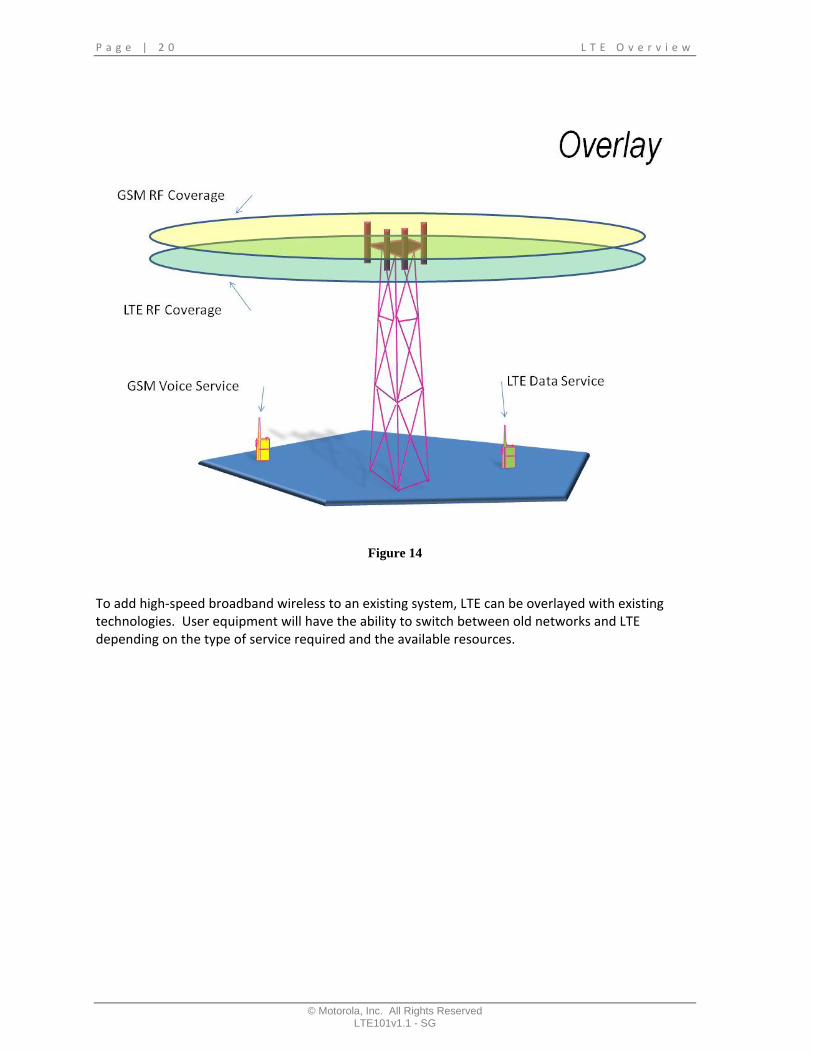
Figure 14
To add high‐speed broadband wireless to an existing system, LTE can be overlayed with existing technologies. User equipment will have the ability to switch between old networks and LTE depending on the type of service required and the available resources.

L T E O v e r v i e w P a g e | 2 1
© Motorola, Inc. All Rights Reserved LTE101v1.0 - SG
Figure 15
Finally, another key benefit of LTE and the Evolved Packet Core is its ability to support seamless operations between RATs.
User equipment has the ability to switch between technologies based on signal quality and resource availability.

P a g e | 2 2 L T E O v e r v i e w
© Motorola, Inc. All Rights Reserved LTE101v1.1 - SG

L T E O v e r v i e w P a g e | 2 3
© Motorola, Inc. All Rights Reserved LTE101v1.0 - SG
Lesson 3: LTE Air Interface (EUTRAN)
Objectives
In this lesson, we are going to focus on the LTE air interface. Here are the objectives for this lesson. At the end of this session, you should be able:
1. List the type of duplexing used in LTE.
2. List the main characteristics of the LTE radio channel.
3. Describe the advanced technologies used in LTE.
4. Explain how advanced radio technologies support the efficient delivery of data.
5. Describe the basic function of OFDMA and SC‐FDMA.
6. Explain the basic purpose of MIMO
7. Explain adaptive modulation

P a g e | 2 4 L T E O v e r v i e w
© Motorola, Inc. All Rights Reserved LTE101v1.1 - SG
Figure 16
One of the most demanding portions of a cellular system is the radio interface. Radio environments are complex and have to take into account multiple characteristics of the radio path. To accomplish this, the radio system has to have the ability to adapt effortlessly for each user on the network.

L T E O v e r v i e w P a g e | 2 5
© Motorola, Inc. All Rights Reserved LTE101v1.0 - SG
Figure 17
Efficiency is another key aspect that has to be considered when developing a radio access technology. The system has to be able to support multiple users, each with different bandwidth requirements and each in different radio conditions.

P a g e | 2 6 L T E O v e r v i e w
© Motorola, Inc. All Rights Reserved LTE101v1.1 - SG
Figure 18
The Evolved UTRAN radio link takes into account both the harsh radio environment and the extreme bandwidth requirements. LTE uses the most advanced technology available to date. This includes adaptive modulation, advanced antenna technology, and adaptive power control.
The radio link also was designed to operate over a wide range of the radio spectrum and has ability to easily adjust to different assigned channel bandwidths. To add to its flexibility, the LTE standard supports both Frequency division duplexing and time division duplexing.

L T E O v e r v i e w P a g e | 2 7
© Motorola, Inc. All Rights Reserved LTE101v1.0 - SG
Figure 19
One of the key considerations taken into account when the LTE standard was written was that the system had to be capable of operating in multitude of frequency bands.
Because of differing government requirements and available spectrum, LTE is being developed to operate in frequency bands all over the radio spectrum, ranging from the 400’s to the high end of UHF.

P a g e | 2 8 L T E O v e r v i e w
© Motorola, Inc. All Rights Reserved LTE101v1.1 - SG
Figure 20
Within each of these frequency bands, the system had to be flexible enough to support channel sizes that range from 1.25 megahertz to 20 megahertz. Channel bandwidth is usually defined by local government regulations.
L T E O v e r v i e w P a g e | 2 9
© Motorola, Inc. All Rights Reserved LTE101v1.0 - SG
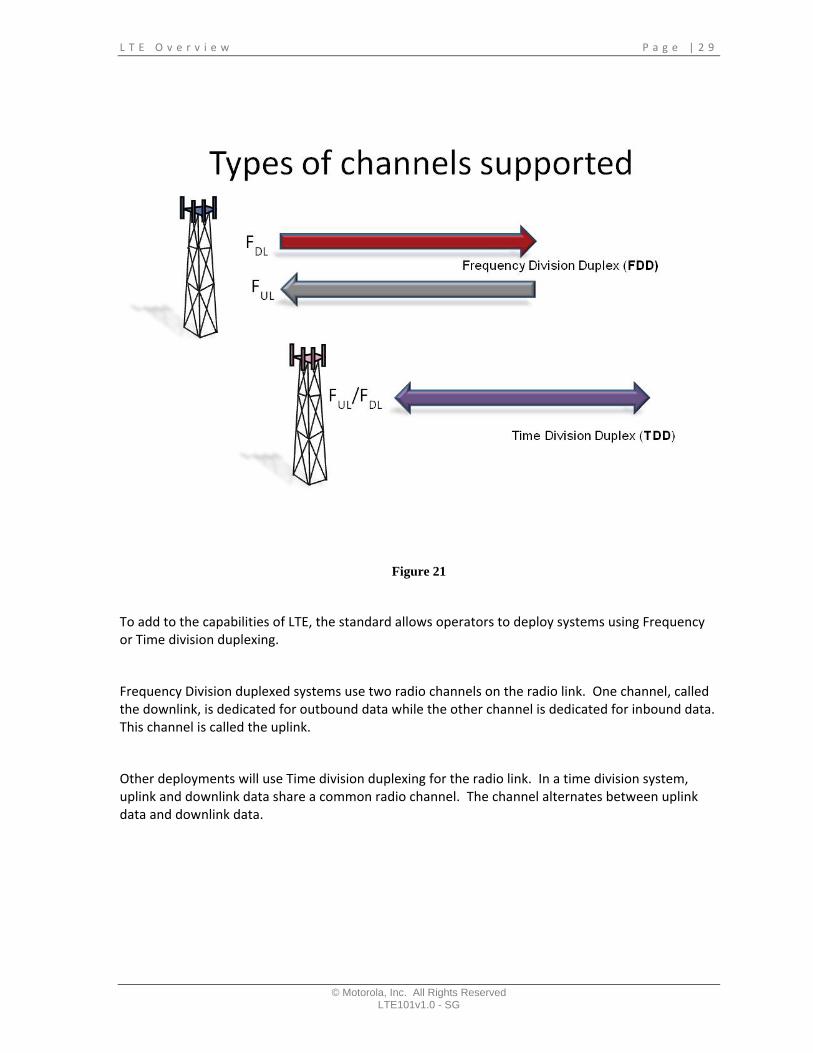
Figure 21
To add to the capabilities of LTE, the standard allows operators to deploy systems using Frequency or Time division duplexing.
Frequency Division duplexed systems use two radio channels on the radio link. One channel, called the downlink, is dedicated for outbound data while the other channel is dedicated for inbound data. This channel is called the uplink.
Other deployments will use Time division duplexing for the radio link. In a time division system, uplink and downlink data share a common radio channel. The channel alternates between uplink data and downlink data.

P a g e | 3 0 L T E O v e r v i e w
© Motorola, Inc. All Rights Reserved LTE101v1.1 - SG
Figure 22
One of the key reasons wireless broadband data is capable of successfully transmitting so much data is because of the type of modulation used. On the downlink, LTE uses OFDMA, while on the uplink single carrier FDMA is used.

L T E O v e r v i e w P a g e | 3 1
© Motorola, Inc. All Rights Reserved LTE101v1.0 - SG
Figure 23
OFDMA systems use multiple subcarriers to transmit data. A high speed data signal is divided into slower data streams and each stream transmitted simultaneously. Using this approach allows the system to transmit support multiple simultaneous users, while minimizing the effects of the harsh radio environment.

P a g e | 3 2 L T E O v e r v i e w
© Motorola, Inc. All Rights Reserved LTE101v1.1 - SG
Figure 24
Single Carrier Frequency Division Multiple Access is used on the uplink. This modulation method is similar to OFDMA but has several characteristics that improve the performance of the user equipment. Like OFDMA, SC‐FDMA provides RF resources to multiple users at the same time.

L T E O v e r v i e w P a g e | 3 3
© Motorola, Inc. All Rights Reserved LTE101v1.0 - SG
Figure 25
To take advantage of the RF channel conditions, LTE will adjust the modulation scheme it uses to efficiently send data over the air interface. As channel conditions begin to deteriorate, the bit error rate will begin to climb. To combat this increase in bit error, the system will change to a less robust modulation scheme. This will decrease the number of bit errors received across the channel.

P a g e | 3 4 L T E O v e r v i e w
© Motorola, Inc. All Rights Reserved LTE101v1.1 - SG
Figure 26
The system uses other methods to combat bit errors. One of the most innovated techniques is a multiple antenna technical called MIMO (Multiple‐In Multiple‐Out). MIMO systems use multiple antennas to minimize errors caused by multipath interference. And because MIMO will increase the overall gain of the system, the overall transmit power required to transmit the data can be reduced.
MIMO works by transmitting data streams in parallel over uncorrelated antennas and radio paths. The result is the radio will receive two separate data streams. The receiver will be able to use the multiple radio streams to correct for data errors received over the air, resulting in overall improved network performance.

L T E O v e r v i e w P a g e | 3 5
© Motorola, Inc. All Rights Reserved LTE101v1.0 - SG
Figure 27
MIMO can be used to increase the data rate of a single user or increase the cell capacity by supplying service to multiple users at the same time. Tin both cases, the receiver has the ability to minimize data errors and reconstruct the original data.

P a g e | 3 6 L T E O v e r v i e w
© Motorola, Inc. All Rights Reserved LTE101v1.1 - SG
Figure 28
Another important improvement with the release of LTE is the improvement in latency. Latency is the amount of delay encountered when a packet moves from source to destination. LTE improvement in latency is gained by improvements in both the air interface and the network.

L T E O v e r v i e w P a g e | 3 7
© Motorola, Inc. All Rights Reserved LTE101v1.0 - SG
Figure 29
To support real‐time, near real‐time and best effort services, LTE establishes quality of service for both the air interface and the network. QoS level are set to ensure services is delivered based on bit rate allowed, priority, and allowable latency.

P a g e | 3 8 L T E O v e r v i e w
© Motorola, Inc. All Rights Reserved LTE101v1.1 - SG
L T E O v e r v i e w P a g e | 3 9
© Motorola, Inc. All Rights Reserved LTE101v1.0 - SG
Lesson 4: Evolved Packet System (EPC and EUTRAN)
Objectives
In this lesson we are going to take a closer look at the network requirements, design, and Motorola solution for LTE. At the end of this lesson, you should be able to:
1. List the key requirements for the network.
2. Organize the Enhanced packet system by function.
3. List the two main portions of the enhanced Packet System.
4. List the function of key network elements deployed in the SAE.
5. Describe the basic characteristics of the Motorola Broadband Data Gateway, Motorola Mobility Manager, and the Enhanced E‐UTRAN.
6. Identify the hardware components used in Motorola’s LTE solution
7. Describe the different eNodeB configurations supported by the Motorola LTE solution

P a g e | 4 0 L T E O v e r v i e w
© Motorola, Inc. All Rights Reserved LTE101v1.1 - SG
Figure 30
Look at the requirements of the System Architecture Evolution. To provide the end‐to‐end performance the network requires, the system has to support a high data throughput with low latency. The design requires a flatter simpler core network that uses packet based IP as the main protocol.
In addition to these network characteristics, the network has to support seamless operations between other Radio Access Technologies. This includes other second and 3rd generation systems, other LTE network, WiMAX, and WLANs. The network also has to support handovers to GSM, GPRS, Edge networks.

L T E O v e r v i e w P a g e | 4 1
© Motorola, Inc. All Rights Reserved LTE101v1.0 - SG
Figure 31
When we begin to look at LTE, we realize that the Enhanced Packet System includes the Enhanced Packet Core, and the E‐UTRAN. But to offer a complete access solution, we must include backhaul between the cell sites and the core, a high speed IP/MPLS network, a data center for support functionality, an Operational and Business Support System, and an advanced IMS network to provide services and features.

P a g e | 4 2 L T E O v e r v i e w
© Motorola, Inc. All Rights Reserved LTE101v1.1 - SG
Figure 32
Within each subsystem there are a number of network devices each adding to the functional operations of the network. Here we will point out a few of the more important devices. In the data center we have typical network devices which include a DNS server, a DHCP server, a network time protocol server the LTE Policy manager, Triple A, and HSS.
In the OSS‐BSS we have the Element and Network Management systems along with the Device management systems. In the access network or Enhanced UTRAN, we have the ENodeB.
Lastly, in the service edge network, or Evolved Packet Core, we have the Motorola Wireless Broadband Controller and the Wireless Gateway Controllers.

L T E O v e r v i e w P a g e | 4 3
© Motorola, Inc. All Rights Reserved LTE101v1.0 - SG
Figure 33
Now that we understand the basic network organization, and some of the network elements in the network, it is important to make sure we understand some of the common terms used for each device. Within the Wireless Service Edge Gateway Motorola defined a Wireless Broadband controller and a Wireless Broadband Gateway. If we switch to 3GPP /LTE terminology, these devices would be called the MME, the servicing gateway, and the packet data network gateway.

P a g e | 4 4 L T E O v e r v i e w
© Motorola, Inc. All Rights Reserved LTE101v1.1 - SG
Figure 34
One of the key benefits of LTE was the simplification of the network. If you compare the architectures of a UMTS system and LTE SAE, you will notice a significant reduction in the number of network elements required to process a call.
Notice that the Evolved UTRAN consists only of the evolved NodeB.
L T E O v e r v i e w P a g e | 4 5
© Motorola, Inc. All Rights Reserved LTE101v1.0 - SG
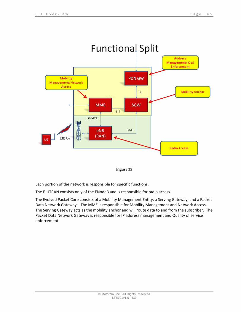
Figure 35
Each portion of the network is responsible for specific functions.
The E‐UTRAN consists only of the ENodeB and is responsible for radio access.
The Evolved Packet Core consists of a Mobility Management Entity, a Serving Gateway, and a Packet Data Network Gateway. The MME is responsible for Mobility Management and Network Access. The Serving Gateway acts as the mobility anchor and will route data to and from the subscriber. The Packet Data Network Gateway is responsible for IP address management and Quality of service enforcement.

P a g e | 4 6 L T E O v e r v i e w
© Motorola, Inc. All Rights Reserved LTE101v1.1 - SG
Figure 36
In addition to these devices, we want to add a few other key network elements. These new elements work in conjunction with the rest of the network to make the network Function.
The Home Subscriber Server or HSS is the master database for all User Entities. The HSS provides the MME with authentication data used when a UE authenticates.
The Policy and Charging Function or PCRF is responsible for managing data traffic for each user entity. It will match user’s profiles to control the Quality of Service, data throughput.
L T E O v e r v i e w P a g e | 4 7
© Motorola, Inc. All Rights Reserved LTE101v1.0 - SG
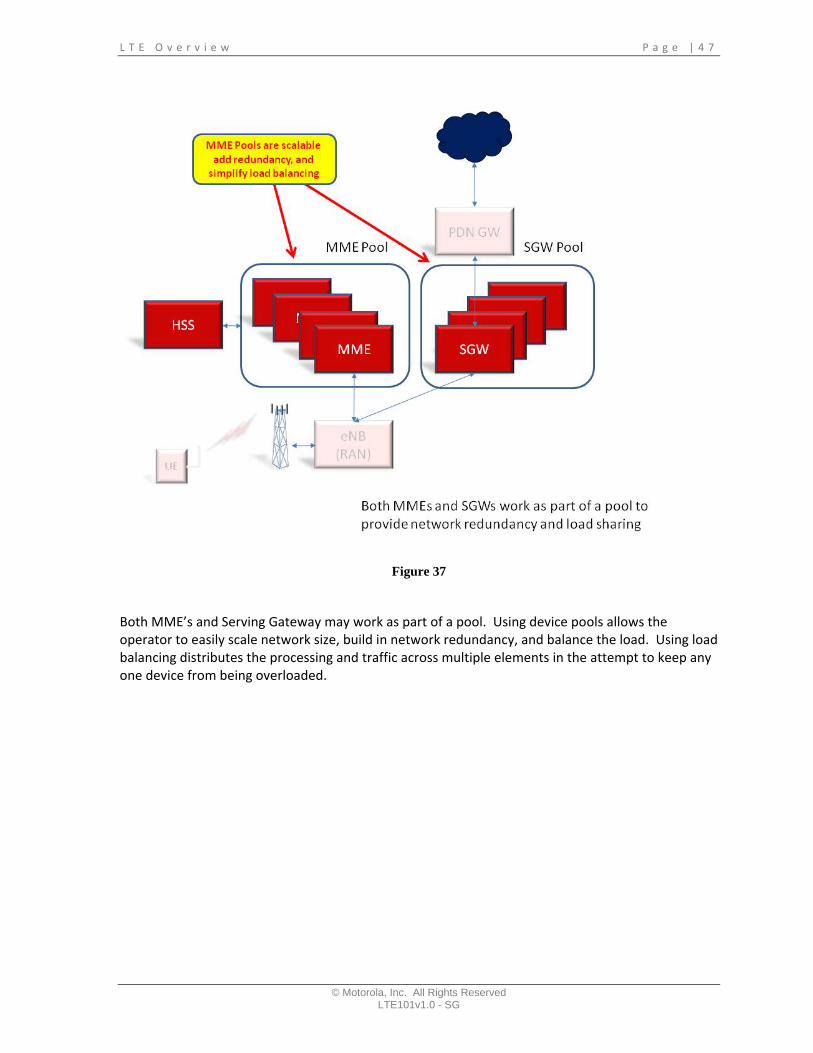
Figure 37
Both MME’s and Serving Gateway may work as part of a pool. Using device pools allows the operator to easily scale network size, build in network redundancy, and balance the load. Using load balancing distributes the processing and traffic across multiple elements in the attempt to keep any one device from being overloaded.

P a g e | 4 8 L T E O v e r v i e w
© Motorola, Inc. All Rights Reserved LTE101v1.1 - SG
Figure 38
Logically, the ENodeB’s connect to both the MME and Serving Gateway. Additionally, ENodeB’s connect to other ENodeB’s to minimize latency and improve performance during handovers.

L T E O v e r v i e w P a g e | 4 9
© Motorola, Inc. All Rights Reserved LTE101v1.0 - SG
Figure 39
To add to the networks adaptability, the ENodeB's have the ability to attach to multiple MME and serving gateway pools. This adds a large amount of flexibility for operator to connect ENodeB's to multiple markets or to other operators.

P a g e | 5 0 L T E O v e r v i e w
© Motorola, Inc. All Rights Reserved LTE101v1.1 - SG
Figure 40
Another feature of 3GPP’s release 8 is that the network has to be able to support seamless traffic from other Radio Access Technologies. Traffic from other 3GPP technologies would be routed through the Serving GPRS Support node. The SGSN maintains connectivity to the SGW and the PDN gateway.

L T E O v e r v i e w P a g e | 5 1
© Motorola, Inc. All Rights Reserved LTE101v1.0 - SG
Figure 41
Now that we have looked at the basic network design, let’s take a look at Motorola’s LTE solution. The focus of this section is on the Enhanced Packet Core and the E‐UTRAN.

P a g e | 5 2 L T E O v e r v i e w
© Motorola, Inc. All Rights Reserved LTE101v1.1 - SG
Figure 42
The E‐UTRAN consists of a single element, called the eNodeB. Motorola’s has build a eNodeB using a modular approach. The eNodeB consists of two main subsystems. The first is the Radio subsystem and the second is the Baseband modem. This design allows our system to be flexible and scalable to easily meet diverse customer requirements.

L T E O v e r v i e w P a g e | 5 3
© Motorola, Inc. All Rights Reserved LTE101v1.0 - SG
Figure 43
In addition to supporting multiple frequency bands of operations, the eNodeB can be deployed in multiple configurations. As a framed based cell site, all of the elements are mounted in a single 19 inch frame. The eNodeB can also be deployed using different radio subsystem. These include a tower‐top, a remote radio head configuration, or as a retrofit to current Motorola deployed GSM equipment.

P a g e | 5 4 L T E O v e r v i e w
© Motorola, Inc. All Rights Reserved LTE101v1.1 - SG
Figure 44

L T E O v e r v i e w P a g e | 5 5
© Motorola, Inc. All Rights Reserved LTE101v1.0 - SG
Figure 45
The Wireless service edge network or EPC consists of the WBC and the WBG. Using 3GPP terminology, these devices are called the MME, the SGW, and the PDN.

P a g e | 5 6 L T E O v e r v i e w
© Motorola, Inc. All Rights Reserved LTE101v1.1 - SG
Figure 46
The wireless broadband controller platform is based on an Advanced TCA communications server. The architecture for these platforms has been used in countless other communication system including Motorola’s WiMAX solution and is based on well known industry standards. Each box fits in a standard 19 inch rack and is designed in a modular fashion allowing it to be easily sized to meet customer expectations.
Capacity will increase with the introduction of the 1440 platform in release one phase 3.

L T E O v e r v i e w P a g e | 5 7
© Motorola, Inc. All Rights Reserved LTE101v1.0 - SG
Figure 47
The Wireless Broadband Gateway is based on industry proven multimedia server platform. The hardware is a fault tolerant carrier class router. These gateways use a fully redundant distributed architecture designed to support a large number of users with large bandwidth demands. Both the serving gateway and the packet data network gateway use the same hardware and can be deployed as separate devices or functionality can be combined.

P a g e | 5 8 L T E O v e r v i e w
© Motorola, Inc. All Rights Reserved LTE101v1.1 - SG
Figure 48
To manage the EPC and the E‐UTRAN, Motorola is deploying the LTE manager. The LTE manager is a element management system designed to provide operators a single location to manage, monitor, and upgrade the network. The LTE manager has a graphical user interface and is based on a Sun Microsystems platform.

L T E O v e r v i e w P a g e | 5 9
© Motorola, Inc. All Rights Reserved LTE101v1.0 - SG

P a g e | 6 0 L T E O v e r v i e w
© Motorola, Inc. All Rights Reserved LTE101v1.1 - SG

L T E O v e r v i e w P a g e | 6 1
© Motorola, Inc. All Rights Reserved LTE101v1.0 - SG
Lesson 5: LTE Call Processing
Objectives
In this lesson we are going to address the most important part of the LTE, placing calls. To do this, here are the objectives for this lesson. At the end of this lesson you should be able to:
1. List the main steps involved in a UE network attach.
2. Describe the mobility management states.
3. Describe the RRC connect process.
4. Describe the EPC connect process.
5. Describe the call processing procedure.
6. Describe the target area update procedure.
7. Describe the handover process.
8. Describe paging.
9. Describe how the UE request additional bandwidth.
10. Describe how the UE detaches from the network.

P a g e | 6 2 L T E O v e r v i e w
© Motorola, Inc. All Rights Reserved LTE101v1.1 - SG
Figure 49
Before we begin, let review the basic LTE building blocks. First we have the evolved UTRAN. In an LTE system, this only includes the e‐NODEB. The e‐node B is responsible for many network functions, including Radio bearer control, Radio admission control, Radio Resource Control, Scheduling, and controlling the physical layer operations.
The Evolve Packet Core consists of the MME, The SGW and the PGW. Each of these network elements are responsible for specific network functionality. The MME is responsible for NAS security, idle state mobility management, and Evolved Packet System bearer control.
The SGW is the mobility anchor for UE and the P‐GW working with some of the support servers is responsible for UE IP addresses and packet control and filtering.

L T E O v e r v i e w P a g e | 6 3
© Motorola, Inc. All Rights Reserved LTE101v1.0 - SG
Figure 50
In order to make this work, IP networks are designed using multiple protocols. Each protocol is responsible for specific functionality. To make the system function, protocols work with other protocols to send and receive data over the air, or through the network. Data is sent up or down the stack of protocols to add or manipulate the data to ensure it is routed correctly, efficiently transmitted, and is received with minimal errors.

P a g e | 6 4 L T E O v e r v i e w
© Motorola, Inc. All Rights Reserved LTE101v1.1 - SG
Figure 51
It the LTE system, protocol stacks are used to transmit control information and bearer, or user traffic. Control information is sent over the control plane, while bearer information is sent over the user plane.

L T E O v e r v i e w P a g e | 6 5
© Motorola, Inc. All Rights Reserved LTE101v1.0 - SG
Figure 52
Here is a simplified view of the protocol stack. In this diagram we have a control and bearer layer, a logical layer, and transport layer, and a physical layer.
Protocols work together by performing their specific function sending data to the next protocol in the stack. For example, if we were sending outbound data the PDCP layer would perform its function, and pass the data down to the next layer. Following the rules of the logical layer, data would be appended and sent to the transport layer. Data would be modified or controlled depending on the rules of the transport layer, and send to the physical layer. The physical layer would modify the data based on its rules and send the data out of the stack.
Inbound data would follow a similar process, except it would move up the protocol stack.
Control data is routed to the RRC portion of the protocol stack, while user data is routed to the PDCP portion of the stack. Now let’s look at each of these stacks in a little more detail.

P a g e | 6 6 L T E O v e r v i e w
© Motorola, Inc. All Rights Reserved LTE101v1.1 - SG
Figure 53
In a real LTE system the protocol stack looks like this. Functionality is organized into layers. Layer one is responsible for the physical Layer. Layer two for the MAC layer and the Radio Link Control layer. And Layer 3 is responsible for the Radio Resource Control or the PDCP layers. If we had data that had to be transmitted, it would traverse down from layer 3 to the RLC layer. The RLC layer would modify it according to the RLC rules and send it to the MAC layer in a logical channel. The MAC layer would modify the data again, and send it to the physical layer in a transport channel. The Physical Layer would modify it again and send it to the transceiver in a physical channel.

L T E O v e r v i e w P a g e | 6 7
© Motorola, Inc. All Rights Reserved LTE101v1.0 - SG
Figure 54
The control plane protocol stack looks like this. There are protocols established to support the physical layer, MAC, Radio Link, and Radio control functionality. These protocols are called AS protocols and are only needed in the E‐UTRAN. There is one additional protocol that we need to be aware of in this stack. This is the NAS protocol. This protocol is responsible for sending information to the EPC.

P a g e | 6 8 L T E O v e r v i e w
© Motorola, Inc. All Rights Reserved LTE101v1.1 - SG
Figure 55
The user plane has many similarities to the control plane. However, this protocol stack is responsible for user data. Notice that there are protocol rules established for the Physical MAC, and Radio Link for control of the air interface. However to send data from the EPC, the user plane uses PDCP as the protocol.

L T E O v e r v i e w P a g e | 6 9
© Motorola, Inc. All Rights Reserved LTE101v1.0 - SG
Figure 56
Now that we have looked at the basics of the protocol stacks, let look at how an UE enters the network and obtains service. In the simplest view, it is a three step process. First the UE has to find and attach to the access network. Once the UE has established this connection, it moves to step 2 and attaches to the EPC. In the EPC, the UE will authenticate and establish an IP connection to the IMS. The last step is establishing a connection with the server supporting the service request. This step varies widely, depending on the network configuration and the type of service request.
Let look at each of these steps in a little more detail.

P a g e | 7 0 L T E O v e r v i e w
© Motorola, Inc. All Rights Reserved LTE101v1.1 - SG
Figure 57
The first step is to attach to the access network. When User Equipment is turned on, it will begin to look for a LTE signal to use. It will scan multiple frequencies, looking for a channel that can provide service. Once it finds a suitable radio channel, it will camp on that cell and begin the attach procedure.

L T E O v e r v i e w P a g e | 7 1
© Motorola, Inc. All Rights Reserved LTE101v1.0 - SG
Figure 58
The E‐UTRAN attach procedure includes establishing timing, understanding channel capabilities, adjusting transmit power, and requesting access.
Once the UE attaches to the Access network, the UE will begin sending NAS messages to the EPC. There are multiple messages sent between the UE and the EPC during attach. The process is to authenticate and register with the MME. The MME will select a serving gateway and based on the UE profile a Packet Data Network Gateway will be chosen. When these steps are completed, the MME will send an accept message to the UE and the UE will reply with an acknowledgement.

P a g e | 7 2 L T E O v e r v i e w
© Motorola, Inc. All Rights Reserved LTE101v1.1 - SG
Figure 59
Here is another way to look at the network attach process. When user equipment is turned on, it begins in the RRC idle state. Once it finds a suitable site, it will attach to the E‐UTRAN. Next the UE will begin it registration process with the EPC. When that process is completed the UE will enter the EMM registered state.
Depending on if the UE is idle or needs to send data will determine what the next state is. When the UE is not actively sending data, it will enter the idle state. When the UE is sending data, it enters the connect state.

L T E O v e r v i e w P a g e | 7 3
© Motorola, Inc. All Rights Reserved LTE101v1.0 - SG
Figure 60
There are five basic call processing procedures we need to cover in order to a better understanding of how LTE users are connected to the network. These five procedures are Attach, Service Request, Tracking Area Updates, Handovers, and Detach messages.
Attach messages occur when a UE is first connecting to the network. Service requests happen when a UE needs to send data or the network needs to send data to a UE. Tracking area updates occur when an idle UE moves from one tracking area to another. In contrast, Handovers occur when a UE is active in a call. And finally, detach is the process of turning a UE off and disconnecting from the network.

P a g e | 7 4 L T E O v e r v i e w
© Motorola, Inc. All Rights Reserved LTE101v1.1 - SG
Figure 61
To attach to the network, we follow 5 basic steps. First the UE sends an attach request to the E‐UTRAN followed by an “attach” to the MME in the EPC. The working with data supplied by the HSS, the MME will send an authentication challenge to the UE. If the UE response correctly, the MME will request bearer services from the SGW and the PDN gateway. If bearer services are established, the gateways respond to the MME with an “attach” accept message. The MME will send an “attach” accept to both the eNodeB and the UE.
Once this is completed, the UE will have been assigned an IP address and a bearer connection with Quality of Service levels will be established.

L T E O v e r v i e w P a g e | 7 5
© Motorola, Inc. All Rights Reserved LTE101v1.0 - SG
Figure 62
When a UE has to send data, it will request service. The first step is for the UE to request resources from the eNodeB. Next, the UE will authenticate. The MME will send a set‐up message to establish the bearer channel. Once the bearer resources are established, data will be send over the bearer plane from the UE through the eNodeB, to the serving gateway, to the PDN gateway, and finally to the IMS system.
P a g e | 7 6 L T E O v e r v i e w
© Motorola, Inc. All Rights Reserved LTE101v1.1 - SG
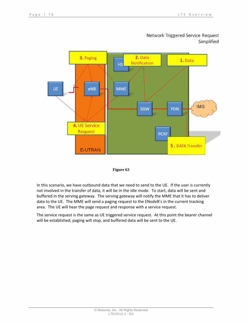
Figure 63
In this scenario, we have outbound data that we need to send to the UE. If the user is currently not involved in the transfer of data, it will be in the idle mode. To start, data will be sent and buffered in the serving gateway. The serving gateway will notify the MME that it has to deliver data to the UE. The MME will send a paging request to the ENodeB’s in the current tracking area. The UE will hear the page request and response with a service request.
The service request is the same as UE triggered service request. At this point the bearer channel will be established, paging will stop, and buffered data will be sent to the UE.

L T E O v e r v i e w P a g e | 7 7
© Motorola, Inc. All Rights Reserved LTE101v1.0 - SG
Figure 64
In this procedure, we are going to look at a UE detach request. When a UE detaches from the network, it will send a NAS message to the MME. The MME will delete the bearer resources established and the policy manager will release the session. When this is completed, the MME will send a “detach” accept message back to the UE.

P a g e | 7 8 L T E O v e r v i e w
© Motorola, Inc. All Rights Reserved LTE101v1.1 - SG
Figure 65
So far, we have looked at basic signaling which included attach, UE initiated and Network initiated data transfer, and a UE detach process. There are two more scenarios we need to be familiar with. These scenarios have to deal with mobility. The UE can be in one of two states, idle or connected. In the idle mode the network will track the UE at a much higher granularity, called tracking areas. The network is organized into groups of cells call tracking areas. UE’s will only update the network if it moves into a new tracking area. Moves from one tracking area to another in idle mode are called reconnects.
When a UE is not idle, it is the connect state. In this state the UE is actively sending and receiving data. In the connect state, the UE will be tracked from cell to cell within the tracking area. When coverage from one site begins to deteriorate, the UE will move from to a better serving cell. Changing cells in the connect mode are called handovers.

L T E O v e r v i e w P a g e | 7 9
© Motorola, Inc. All Rights Reserved LTE101v1.0 - SG
Figure 66
In the idle mode, the user equipment will need to update the system when it moves from one tracking area to another. When a UE moves from tracking area 2 to tracking area 1, it will send a tracking area update request to the eNodeB and the MME. The MME will update the UE location information in the HSS and respond to the MEE with an accept message. The MME will send an accept message back to the UE to complete the process.

P a g e | 8 0 L T E O v e r v i e w
© Motorola, Inc. All Rights Reserved LTE101v1.1 - SG
Figure 67
Next we need to look at the procedure when a UE is involved in a handover. First, we need to set‐up the scenario. In this example, the UE is camped on cell 1. This is called the serving cell. The UE is going to be moving away from cell 1 and towards cell 2. Cell 2 is going to be the target cell. The UE will continually monitor neighbor cells and measuring the channel quality. There is one more very important point we need to make with this scenario. Notice that there is a connection between all of the cells. This connection is called the X2 connection. When a subscriber needs to move from one cell to another, the serving cell will forward buffered data to the target cell during the handover.

L T E O v e r v i e w P a g e | 8 1
© Motorola, Inc. All Rights Reserved LTE101v1.0 - SG
Figure 68
Now we are ready for the UE to move. As the user moves, the channel quality index will begin to degrade on the serving cell and improve on the target cell. At one point, the target cell will make a better serving cell than the current cell. At this threshold, we will begin the handover process.

P a g e | 8 2 L T E O v e r v i e w
© Motorola, Inc. All Rights Reserved LTE101v1.1 - SG
Figure 69
To start the handover process the serving cell will send a handover message to the UE. At that point the UE will move to the target cell and the eNodeB will forward data. The eNodeB will also inform the MME to switch the routing to the target cell. The MME will update the serving gateway, and the serving gateway will switch the tunnel from the old serving cell to the target cell. Once this is complete, the target cell will send a release resource to the old serving cell. At this point the target cell will become the new serving cell.
L T E O v e r v i e w P a g e | 8 3
© Motorola, Inc. All Rights Reserved LTE101v1.0 - SG
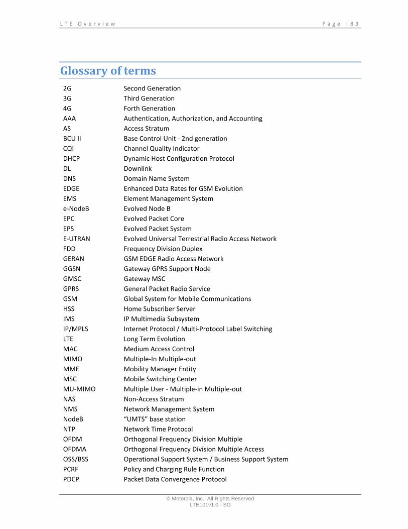
Glossary of terms 2G Second Generation 3G Third Generation 4G Forth Generation AAA Authentication, Authorization, and Accounting AS Access Stratum BCU II Base Control Unit ‐ 2nd generation CQI Channel Quality Indicator DHCP Dynamic Host Configuration Protocol DL Downlink DNS Domain Name System EDGE Enhanced Data Rates for GSM Evolution EMS Element Management System e‐NodeB Evolved Node B EPC Evolved Packet Core EPS Evolved Packet System E‐UTRAN Evolved Universal Terrestrial Radio Access Network FDD Frequency Division Duplex GERAN GSM EDGE Radio Access Network GGSN Gateway GPRS Support Node GMSC Gateway MSC GPRS General Packet Radio Service GSM Global System for Mobile Communications HSS Home Subscriber Server IMS IP Multimedia Subsystem IP/MPLS Internet Protocol / Multi‐Protocol Label Switching LTE Long Term Evolution MAC Medium Access Control MIMO Multiple‐In Multiple‐out MME Mobility Manager Entity MSC Mobile Switching Center MU‐MIMO Multiple User ‐ Multiple‐in Multiple‐out NAS Non‐Access Stratum NMS Network Management System NodeB “UMTS” base station NTP Network Time Protocol OFDM Orthogonal Frequency Division Multiple OFDMA Orthogonal Frequency Division Multiple Access OSS/BSS Operational Support System / Business Support System PCRF Policy and Charging Rule Function PDCP Packet Data Convergence Protocol
P a g e | 8 4 L T E O v e r v i e w
© Motorola, Inc. All Rights Reserved LTE101v1.1 - SG
PDN Packet Data Network Gateway P‐GW Packet Data Network Gateway PHY Physical Layer QAM Quadrature Amplitude Modulation QoS Quality of Service QPSK Quadrature Phase Shift Keying RAN Radio Access Network RAT Radio Access Technology RF Radio Frequency RLC Radio Link Control RNC Radio Network Controller RRC Radio Resource Control RRM Radio Resource Management SAE System Architecture Evolution SC‐FDMA Single Carrier‐Frequency Division Multiple Access SGSN Serving GPRS Support Node S‐GW Serving Gateway SU‐MIMO Single User‐ Multiple‐in Multiple‐Out TA Tracking Area TAU Tracking Area Update TDD Time Division Duplex UE User Equipment UL Uplink UMTS Universal Mobile Telecommunications System UTRA universal Terrestrial Radio Access UTRAN Universal Terrestrial Radio Access Network WBC Wireless Broadband Controller WBG Wireless Broadband Gateway

L T E O v e r v i e w P a g e | 8 5
© Motorola, Inc. All Rights Reserved LTE101v1.0 - SG
EPS Architecture

P a g e | 8 6 L T E O v e r v i e w
© Motorola, Inc. All Rights Reserved LTE101v1.1 - SG


