Embed Size (px)
Citation preview
LTE Radio Resource Management Conformance Testing:
Exploration and Implementation
Dingliang Wang1, Zhizhong Ding
2, Yin Chen
1, and Younan Duan
1
1Department of Communication Engineering, Hefei University of Technology, Hefei, 230009, China
2 Institute of Communication and Information Systems, Hefei University of Technology, Hefei, 230009, China
Email: {wdlwshcjf, hfut_cy}@163.com; [email protected]; [email protected]
Abstract—LTE is an evolution of 3G technology which
possesses 100Mb/s data downloading capability. The
technology of LTE is progressive and puts forward stricter
requirements for terminals. All the LTE wireless terminals must
pass the Radio resource Management (RRM) conformance
testing before entering into the market. This paper first dissected
TTCN-3 test system and RRM testing structure for the purpose
of designing RRM testing model. The testing model proposed in
this paper realized the equal data exchange between test system
(TS) and system under test (SUT) in application layer, and thus
solved a big problem in constructing test platform of RRM
testcases. Then comes the most difficult tasks: develop RRM
testcases, system adapter (SA) and codec (CD). Among the
tasks, RRM testcases are developed based on the test suite
released by European Telecommunication Standards Institute
(ETSI). Important runtime testing processes including
Authentication and Key Agreement (AKA) process, preamble
transfer process and cell reselection process are dissected in
detail for the purpose of programming. SA is developed
according to TRI specification using socket programming. CD
is developed according to TCI specification.. On the basis of
massive practical work, the implementation of RRM
conformance testing is shown. Index Terms—Radio resource management, LTE, TTCN-3,
AKA, Conformance testing
I. INTRODUCTION
3rd Generation Partnership Project (3GPP) started the
research of LTE in November 2004. LTE system can
provide higher transmission rate and lower transmission
delay compared with 3G mobile communication
technology. In order to realize the truly commercial
operation of LTE, the terminal conformance testing must
be done to check whether the produced LTE terminals
satisfy the requirements for technology, signaling and
performance. Terminal conformance testing contains RF
and protocol conformance testing as well as other
conformance testing. RF conformance testing includes
RF characteristics testing and RRM conformance testing.
RRM conformance testing has not been accomplished so
far. This paper focuses on making contributions to the
completion of LTE RRM conformance testing.
RRM aims at providing the guarantee of service
quality and improving radio spectrum utilization as much
Manuscript received September 11, 2014; revised November 25, 2014. Corresponding author email: [email protected]
doi:10.12720/jcm.9.11.867-875
as possible to prevent network congestion and reduce
signaling load. RRM conformance testing is to check
whether the RRM capability of LTE wireless terminals
conforms to the description of LTE standards. Global
Certification Forum (GCF) designates TTCN-3 language
as the only conformance testing criterion, so RRM
conformance testing must be implemented based on
TTCN-3 to achieve its global acceptance.
The implementation of RRM conformance testing is a
tough task since the execution of RRM testcases needs
the support of all the lower-layer protocols such as RRC
(Radio Resource Control), PDCP (Packet Data
Converage Protocol), RLC (Radio Link Control), MAC
(Medium Access Control) and PHY (Physical layer). The
authors have done a lot of work about it. Based on our
experience, this paper first introduces the framework of
RRM conformance testing including TTCN-3 test system
and RRM testing structure. Then, a feasible RRM testing
model is proposed for simulating RRM testing. After that,
the development of SA, CD and SUT (System Under Test)
is shown in detail. TTworkbench is chosen as our
integrated development environment (IDE), and the
whole implementation process of RRM conformance
testing including setting testing environment, configuring
testing parameters, running testcases and getting verdict
result is shown in the final section.
II. OVERALL FRAMEWORK
A. TTCN-3 Test System
TTCN-3 is a powerful and flexible test language
widely used in computer and communication fields, and
ETSI chooses TTCN-3 as the new generation protocol
and software test standard. To achieve the global
promotion of LTE, RRM conformance testing must be
implemented based on TTCN-3.
Templates, data types, constants, timers, altsteps,
components, ports, functions and testcases are defined in
the definitions part of a TTCN-3 module, and the control
part of a TTCN-3 module is responsible for calling
testcases and controlling their running. A TTCN-3
module can also import definitions from other modules
using the keyword “import from” [1], [2].
TTCN-3 core language not only contains the features
of other high-level languages, but also includes its
dedicated structures and objects such as codec module,
Journal of Communications Vol. 9, No. 11, November 2014
©2014 Engineering and Technology Publishing 867
matching mechanism and testing verdict. TTCN-3 core
language can also be transformed into GFT (Graphical
representation format) to clearly show the execution
sequence of TTCN-3 code.
Fig. 1.The structure of TTCN-3 test system
TTCN-3 code is concise and easy to understand, but
the execution of TTCN-3 code needs a lot of tools to
provide support. In C++ or java language, data
transmission can be realized by socket and stream, but
TTCN-3 language defines communication ports in an
abstract way like “port EUTRA_SYSTEM_PORT SYS”
and there are no concepts of socket and stream in TTCN-
3 language. We must develop SA to indicate how and
where the data or signaling should be sent and develop
codec to transform TTCN-3 or ASN.1 data into binary
bit-stream. So, compared with C++ or java, TTCN-3
brings more difficulties for RRM testing. Figure 1 shows
the structure of TTCN-3 test system.
Test management (TM) is responsible for managing
the whole test system, such as loading test suites,
controlling compiler and executor. Test Log (TL) is a
record entity which keeps track of TTCN-3 real-time logs
and outputs the recorded TTCN-3 real-time logs to
console. Components Handler (CH) handles and
coordinates all components, we can take advantage of CH
to achieve distributed testing. Test Executable (TE) is the
executable code compiled from original TTCN-3 script
files. TE is responsible for the interpretive execution of
TTCN-3 modules.
SA, CD and PA constitute the TTCN-3 test adapter.
SA is responsible for establishing and maintaining the
connection to SUT. CD encodes and decodes data and
signaling according to specific rules such as BER, PER
and UPER. PA adapts test system to the given platform,
such as calling external functions. Testers need to
develop SA and CD before executing RRM testcases and
this means a mass of work [3]-[5].
B. RRM Testing Structure
There are about 42 testcases in TD_LTE RRM
conformance testing. The structure of these testcases
conforms to the following testing structure as shown in
Fig. 2.
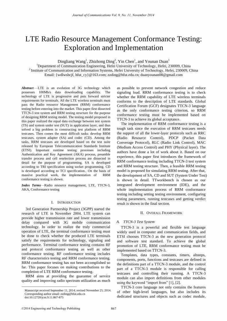
According to the RRM testing structure, it’s obvious
that RRM testing instrument can be logically divided into
user plane protocol stack, control plane protocol stack,
NAS emulation, RAT (Radio Access Technology)
emulation, IP_PTC emulation and cell emulation.
Functions of NAS (Non-Access Stratum) and RRC, such
as NAS security, radio bearer management and mobility
management, are simulated by NAS emulation. RAT
emulation is used for simulating radio access
technologies, such as EUTRAN (Evolved Universal
Terrestrial Radio Access Network) and GERAN (GSM
EDGE Radio Access Network). Two or more RATs are
needed for testing the handover performance of UE. Cell
emulation can produce several simulated cells for UE to
camp on. For example, in cell reselection testcases, all the
cells that can be detected by UE will be measured and UE
will choose the best cell to camp on. There are many
ports in RRM testing such as SRB, DRB, IP_SOCK and
EUTRA_CTRL. All these ports should have the
information of port number and IP address to indicate
where the messages should be sent, so IP_PTC emulation
is needed. IP_PTC emulation handles sockets and routing
information to ensure the sending and receiving in order.
In one word, we must understand well the below RRM
testing structure in order to implement RRM testing [6]-
[8].
Fig. 2. RRM testing structure of LTE
SYS port of EUTRA is responsible for nearly all
configurations including security configuration, radio
bearer configuration, channel configuration, and so on.
Journal of Communications Vol. 9, No. 11, November 2014
©2014 Engineering and Technology Publishing 868
The SYSIND port transfers indication information to
MAC and Physical layer. NASCTRL port and SRB port
interact with NAS emulation. The DRB port carries user
data to the user plane. IP_CTRL and IP_DATA are ports
of IP_PTC. IP_PTC is responsible for interacting with SA.
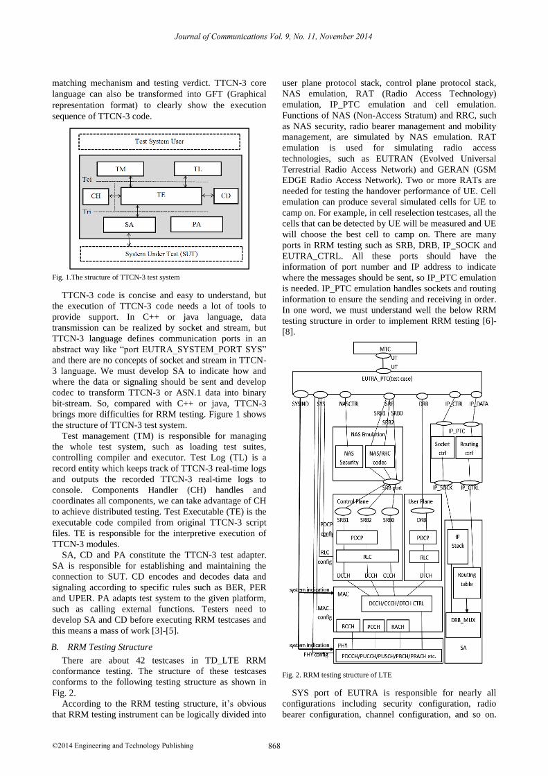
Control plane employs “SCTP (Stream Control
Transmission Protocol) over IP” to transport control
signaling. Control plane protocol stack is shown in Fig. 3.
NAS layer can bypass access network (E-UTRAN) to
interact with core network (EPC, Evolved Packet Core)
directly. NAS layer and RRC layer are simulated by NAS
emulation.
Fig. 3. Control plane protocol stack
User plane adopts UDP (User Datagram Protocol) to
transport user data. Fig. 4 shows the user plane protocol
stack. PDCP layer conducts header compression,
ciphering and integrity protection for user data. RLC
layer then segments the user data and adds a RLC header
for each segment to form RLC PDUs (Protocol Data
Units). MAC layer combines several RLC PDUs into a
MAC data unit and adds a MAC header for each MAC
data unit to form a transmission block. Physical layer
adds a CRC (Cyclic Redundancy Check) field to the end
of the transmission block and finally the transmission
block will be encoded, modulated and sent to air interface.
Fig. 4. User plane protocol stack
LTE channels are divided into physical channels,
transport channels and logical channels. Logical channels
classify messages, different types of messages are
mapped to different logical channels. For example,
control signaling corresponds to CCCH (Common
Control Channel) and DCCH (Dedicated Control
Channel), and user data is mapped to DTCH (Dedicated
Traffic Channel). MAC layer then adds indication
information to logical channel messages and maps them
to transport channels. Transport channels make messages
suit for transmission. Physical channels use specific
carrier, scrambling or time slot to carry messages, so
different message will correspond with different
frequency, code or time slot.
LTE Radio Bearers (RBs) are used for realizing the
connection between UE and eNodeB. SRBs carry
controlling signaling to control plane and DRB carries
user data to user plane. SRBs are divided into SRB0,
SRB1 and SRB2. SRB0 and SRB1 transfer RRC
signaling while SRB2 transfers NAS signaling. The
mapping relations between RBs and LTE channels are
shown in Fig. 5
Fig. 5. The mapping relation between RBs and LTE
channels
III. RELATED WORK
A. Design Testing Model
TTCN-3 test system shown in Figure 1 is quite
complicated, but functions of CH, TL, TM and PA can be
integrated into IDEs like TTworkbench. Therefore,
TTCN-3 test system is simplified as Fig. 6.
Fig. 6. Simplified TTCN-3 test system
On the basis of simplified TTCN-3 test system, RRM
testing model is designed. RRM testing model consists of
Host-PC, testing instrument and UE. Host-PC is
connected to testing instrument with a network cable and
testing instrument communicates with UE by air interface.
Host-PC runs RRM testcases. Testing instrument handles
NAS
RRC
PDCP
RLC
MAC
PHY
RRC
PHY
MAC
PDCP
RLC
MME UE eNodeB
NAS
Test system user
TE
SA (system adapter)
CD(coding and decoding)
SUT (system under test)
Journal of Communications Vol. 9, No. 11, November 2014
©2014 Engineering and Technology Publishing 869
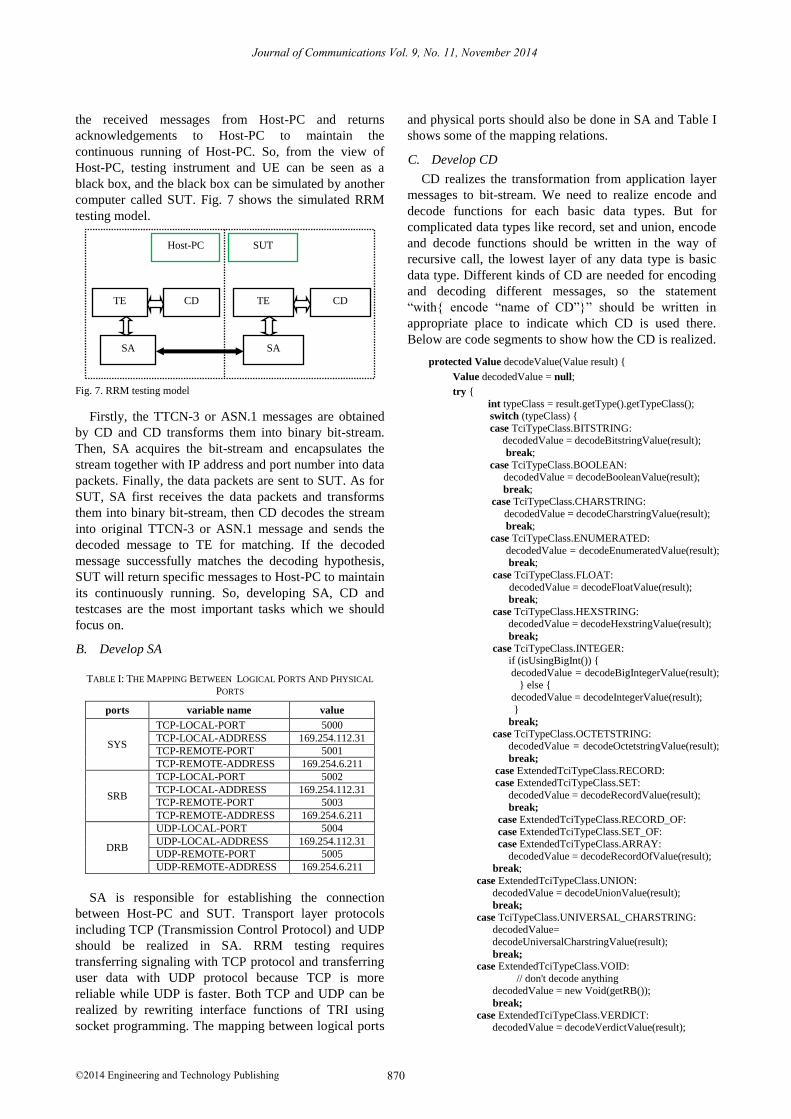
the received messages from Host-PC and returns
acknowledgements to Host-PC to maintain the
continuous running of Host-PC. So, from the view of
Host-PC, testing instrument and UE can be seen as a
black box, and the black box can be simulated by another
computer called SUT. Fig. 7 shows the simulated RRM
testing model.
Fig. 7. RRM testing model
Firstly, the TTCN-3 or ASN.1 messages are obtained
by CD and CD transforms them into binary bit-stream.
Then, SA acquires the bit-stream and encapsulates the
stream together with IP address and port number into data
packets. Finally, the data packets are sent to SUT. As for
SUT, SA first receives the data packets and transforms
them into binary bit-stream, then CD decodes the stream
into original TTCN-3 or ASN.1 message and sends the
decoded message to TE for matching. If the decoded
message successfully matches the decoding hypothesis,
SUT will return specific messages to Host-PC to maintain
its continuously running. So, developing SA, CD and
testcases are the most important tasks which we should
focus on.
B. Develop SA
TABLE I: THE MAPPING BETWEEN LOGICAL PORTS AND PHYSICAL
PORTS
ports variable name value
SYS
TCP-LOCAL-PORT 5000
TCP-LOCAL-ADDRESS 169.254.112.31
TCP-REMOTE-PORT 5001
TCP-REMOTE-ADDRESS 169.254.6.211
SRB
TCP-LOCAL-PORT 5002
TCP-LOCAL-ADDRESS 169.254.112.31
TCP-REMOTE-PORT 5003
TCP-REMOTE-ADDRESS 169.254.6.211
DRB
UDP-LOCAL-PORT 5004
UDP-LOCAL-ADDRESS 169.254.112.31
UDP-REMOTE-PORT 5005
UDP-REMOTE-ADDRESS 169.254.6.211
SA is responsible for establishing the connection
between Host-PC and SUT. Transport layer protocols
including TCP (Transmission Control Protocol) and UDP
should be realized in SA. RRM testing requires
transferring signaling with TCP protocol and transferring
user data with UDP protocol because TCP is more
reliable while UDP is faster. Both TCP and UDP can be
realized by rewriting interface functions of TRI using
socket programming. The mapping between logical ports
and physical ports should also be done in SA and Table I
shows some of the mapping relations.
C. Develop CD
CD realizes the transformation from application layer
messages to bit-stream. We need to realize encode and
decode functions for each basic data types. But for
complicated data types like record, set and union, encode
and decode functions should be written in the way of
recursive call, the lowest layer of any data type is basic
data type. Different kinds of CD are needed for encoding
and decoding different messages, so the statement
“with{ encode “name of CD”}” should be written in
appropriate place to indicate which CD is used there.
Below are code segments to show how the CD is realized.
protected Value decodeValue(Value result) {
Value decodedValue = null;
try {
int typeClass = result.getType().getTypeClass(); switch (typeClass) {
case TciTypeClass.BITSTRING: decodedValue = decodeBitstringValue(result);
break;
case TciTypeClass.BOOLEAN: decodedValue = decodeBooleanValue(result);
break; case TciTypeClass.CHARSTRING:
decodedValue = decodeCharstringValue(result);
break; case TciTypeClass.ENUMERATED:
decodedValue = decodeEnumeratedValue(result); break;
case TciTypeClass.FLOAT:
decodedValue = decodeFloatValue(result); break;
case TciTypeClass.HEXSTRING: decodedValue = decodeHexstringValue(result);
break;
case TciTypeClass.INTEGER: if (isUsingBigInt()) {
decodedValue = decodeBigIntegerValue(result); } else {
decodedValue = decodeIntegerValue(result);
}
break;
case TciTypeClass.OCTETSTRING: decodedValue = decodeOctetstringValue(result);
break;
case ExtendedTciTypeClass.RECORD: case ExtendedTciTypeClass.SET:
decodedValue = decodeRecordValue(result);
break;
case ExtendedTciTypeClass.RECORD_OF:
case ExtendedTciTypeClass.SET_OF: case ExtendedTciTypeClass.ARRAY:
decodedValue = decodeRecordOfValue(result); break;
case ExtendedTciTypeClass.UNION:
decodedValue = decodeUnionValue(result);
break;
case TciTypeClass.UNIVERSAL_CHARSTRING: decodedValue=
decodeUniversalCharstringValue(result);
break;
case ExtendedTciTypeClass.VOID:
// don't decode anything
decodedValue = new Void(getRB());
break;
case ExtendedTciTypeClass.VERDICT: decodedValue = decodeVerdictValue(result);
Host-PC
TE CD
SUT
SA SA
CD TE
Journal of Communications Vol. 9, No. 11, November 2014
©2014 Engineering and Technology Publishing 870
break;
default:
logError("AbstractBitBaseCodecPlugin:Unsupported
type class: " + typeClass, getCurrentComponent()); tciErrorReq("AbstractBitBaseCodecPlugin:
Unsupported type: " + typeClass); }
} catch (Throwable th) {
logWarn("Error occured while decoding: " + Util.throwable2String(th), getCurrentComponent());
return null; }
return decodedValue;
}
D. Construct SUT
As mentioned in section 3.1 (Design Testing Model),
from the view of Host-PC, testing instrument and UE can
be seen as a black box, and the black box can be
simulated by another computer called SUT. So the
problem is how to construct the SUT.
Firstly, there are quite a lot ports needed by RRM
testing and the same amount of ports should be defined in
SUT to establish one-to-one correspondence between
Host-PC and SUT.
type component mtcType { port myPort IP_SOCK;
port myPort IP_CTRL;
port myPort IPSEC_CTRL; port myPort E_DRB;
port myPort Ut;
port myPort E_SYS;
port myPort E_SYSIND;
port myPort E_SRB; }
type component systemType {
port myPort IP_SOCK;
port myPort IP_CTRL; port myPort IPSEC_CTRL;
port myPort DRB; port myPort Ut;
port myPort SYS;
port myPort SYSIND; port myPort SRB;
}
Then, the main body of SUT is constructed. Host-PC
sends a message to SUT and SUT returns the message
expected by Host-PC.
alt {
[] receive(the message expected by SUT) {
localtimer.stop; send (the message expected by Host-PC);
}
[] receive()
{ localtimer.stop;
log(“Unexpected message received”)
} [] localtimer.timeout{ }
}
E. Develop RRM Testcases
RRM testcases are described in the LTE specification
“3GPP TS 36.521-3” and all these testcases need to be
transformed into TTCN-3 code.
The lower layers of protocol conformance testing such
as PDCP, RLC, MAC and PHY are the same as the lower
layers of RRM conformance testing, so our testcases will
be developed based on the test suite of protocol
conformance testing released by ETSI.
EUTRA TDD intra frequency cell reselection testcase
which corresponds to the specification “3GPP TS 36.521-
3.4.2.2” will be used as the example to explain how to
develop RRM testcases. The runtime processes of this
testcase includes Authentication and Key Agreement
(AKA) process, preamble transfer process and cell
reselection process.
When UE is switched on, the service network and the
UE need to authenticate each other and negotiate
necessary keys for security and integrity protection, this
process is called AKA process [9].
There is a permanent key called K stored in USIM and
Authentication Centre (AuC), all the other keys are
derived from K. The key pair CK/IK derived from K is
used for deducing KASME, and KASME is a total key
for deducing all lower-layer keys. Lower-layer keys are
ciphering and integrity protection keys for NAS, RRC
and user plane.
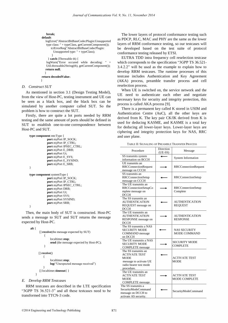
TABLE II: SIGNALING OF PREAMBLE TRANSFER PROCESS
Procedure Direction (UE-SS)
Message
SS transmits system information on BCCH
System Information
UE transmits an RRCConnectionRequest message on CCCH
RRCConnectionRequest
SS transmits an RRCConnectionSetup message on CCCH
RRCConnectionSetup
The UE transmits an RRCConnectionSetupComplete message on DCCH
RRCConnectionSetup
Complete
The SS transmits an AUTHENTICATION REQUEST message on DCCH
AUTHENTICATION
REQUEST
The UE transmits an AUTHENTICATION RESPONSE message on DCCH
AUTHENTICATION
RESPONSE
The SS transmits a NAS SECURITY MODE COMMAND message on DCCH
NAS SECURITY MODE COMMAND
The UE transmits a NAS SECURITY MODE COMPLETE message
SECURITY MODE
COMPLETE
The SS transmits an ACTIVATE TEST MODE message to activate UE radio bearer test mode procedure.
ACTIVATE TEST
MODE
The UE transmits an ACTIVATE TEST MODE COMPLETE message.
ACTIVATE TEST
MODE COMPLETE
The SS transmits a SecurityModeCommand message on DCCH to activate AS security.
SecurityModeCommand
Journal of Communications Vol. 9, No. 11, November 2014
©2014 Engineering and Technology Publishing 871
The UE transmits a SecurityModeComplete message and establishes the initial security configuration.
SecurityModeComplete
The SS transmits a UECapabilityEnquiry message
UECapabilityEnquiry
The UE transmits a UECapabilityInformation message to transfer UE radio access capability.
UECapabilityInformation
The SS transmits an RRCConnectionReconfiguration message to establish the default bearer
RRCConnection Reconfiguration
The UE transmits an RRCConnection ReconfigurationComplete message
RRCConnection
ReconfigurationComplete
This message includes the ATTACH COMPLETE message. The ACTIVATE DEFAULT EPS BEARER CONTEXT ACCEPT message is piggybacked in ATTACH COMPLETE.
NAS: ATTACH COMPLETE;
NAS:ACTIVATE
DEFAULT EPS BEARER CONTEXT ACCEPT
The SS transmits an RRCConnectionRelease message to release RRC connection and move to RRC_IDLE (State 2A).
RRCConnectionRelease
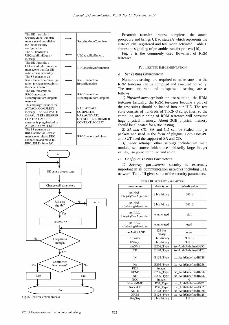
Fig. 8. Cell reselection process
Preamble transfer process completes the attach
procedure and brings UE to state2A which represents the
state of idle, registered and test mode activated. Table II
shows the signaling of preamble transfer process [10].
Fig. 8 is the commonly used flowchart of RRM
testcases.
IV. TESTING IMPLEMENTATION
A. Set Testing Environment
Numerous settings are required to make sure that the
RRM testcases can be compiled and executed correctly.
The most important and indispensable settings are as
follows.
1) Physical memory: both the test suite and the RRM
testcases (actually, the RRM testcases become a part of
the test suite) should be loaded into our IDE. The test
suite consists of hundreds of TTCN-3 script files, so the
compiling and running of RRM testcases will consume
huge physical memory. About 3GB physical memory
should be allocated for RRM testing.
2) SA and CD: SA and CD can be sealed into jar
packets and used in the form of plugins. Both Host-PC
and SUT need the support of SA and CD.
3) Other settings: other settings include: set main
module, set source folder, use arbitrarily large integer
values, use javac compiler, and so on.
B. Configure Testing Parameters
1) Security parameters: security is extremely
important in all communication networks including LTE
network. Table III gives some of the security parameters.
TABLE III: SECURITY PARAMETERS
parameters data type default value
px-NAS-IntegrityProtAlgorithm
3 bits binary ‘001’B
px-NAS-
CipheringAlgorithm 3 bits binary ‘001’B
px-RRC-
IntegrityProtAlgorithm enumerated eia1
px-RRC-CipheringAlgorithm
enumerated eea0
px-eAuthRAND 128 bits binary
none
KSIasme 3 bits binary ‘111’B
KSIsgsn 3 bits binary ‘111’B
KASME B256_Type tsc-AuthUndefinedB256
CK B128_Type tsc-AuthUndefinedB128
IK B128_Type tsc_AuthUndefinedB128
Ks B256_Type tsc_AuthUndefinedB256
KDF integer 1
KENB B256_Type tsc_AuthUndefinedB256
NH B256_Type tsc_AuthUndefinedB256
NCC integer 0
NonceMME B32_Type tsc_AuthUndefinedB32
NonceUE B32_Type tsc_AuthUndefinedB32
AUTH B128_Type tsc_AuthUndefinedB128
XRES B128_Type tsc_AuthUndefinedB128
KeySeq 3 bits binary ‘111’B
Start
Change cell parameters
UE acts
rightly? Fail++
success ++
UE enters proper state
Loop times
enough?
Confidence level meets?
Pass Fail
End
No
Yes
Yes
No
Yes No
Journal of Communications Vol. 9, No. 11, November 2014
©2014 Engineering and Technology Publishing 872
TABLE IV: MAIN TESTING PARAMETERS
parameters units Cell1 Cell2
T1 T2 T3 T1 T2 T3
E-UTRA
RF channel number
1 1
BW MHZ 10 10
OCNG OP.2 TDD OP.2 TDD
PBCH-RA
dB 0 0
PBCH-RB
PSS-RA
SSS-RA
PCFICH-RB
PHICH-RA
PHICH-RB
PDCCH-
RA
PDCCH-RB
PDSCH-RA
PDSCH-RB
OCNG-RA
OCNG-RB
Qrxlevmin dBm -140 -140
Pcompensat
ion dB 0 0
Qhysts dB 0 0
Qoffset dB 0 0
Measuremen-t variable
RSRP RSRP
Es/Iot dB 16.
00 -3.55
3.2
4
-
∞ 3.24
-
3.5
5
Noc
(AWGN)
dBm/15
KHZ -98
Es/ Noc dB 16 13 16 -
∞
16.45
13
RSRP dBm/15
KHZ -82 -85
-
81.55
-
∞ -81.5 -85
Treselection s 0 0 0 0 0 0
Sintrasearch dB Not send Not send
Propagation
condition AWGN
2) Main testing parameters:
Main testing parameters are parameters that must be
configured for executing RRM testcases. TABLE IV
shows the configuration of main testing parameters.
OCNG represents the OFDM Channel Noise Generator, it
is a method for simulating real testing environment. Noc
represents Additive White Gaussian Noise (AWGN)
power spectral density. Es/Iot represents the ratio of the
received energy per RE (Resource Element) to the
received power spectral density of the total noise and
interference for a certain RE. Es/Noc represents the signal
to noise ratio. Qhysts is the cell reselection Hysteresis
value which is used to avoid frequently cell reselection.
Qhysts acts on service cell and the change of Qhysts
value will influence the relations between service cell and
all its neighbor cells. Qoffset describes the RSRP offset
value between service cell and its neighbor cells. The
larger the Qoffset value is, the harder the cell reselection
actions can be carried out. Qoffset acts on neighbor cells,
so it can be used more flexible. Sintrasearch is the intra
frequency measurement trigger gate of cell reselection.
Treselection is the time value of cell reselection timer.
Only the cell which satisfies cell reselection criteria and
lasts the time of Treselection can be selected as a new
service cell.
3) Special parameters:
There are many special parameters that shared by most
testcases such as pc_Attach, pc_Combined_Attach,
pc_IPv4, px_AccessPointName, pc_SwitchOnOff and
pc_eTDD. Some of these parameters are not necessary to
be configured and we can just use their default values, but
others must be configured according to concrete testcase.
If you do not configure them, the testcase will be
terminated at somewhere. It is strongly adviced that all
the special parameters be configured so that you do not
need to worry about abnormal terminations. The values of
these parameters can be modified in the source file, but it
is better to set the parameter values in the runtime GUI so
that different parameter values are applied to different
testcases. Table V gives some of the special parameters
that should be configured.
TABLE V: SPECIAL PARAMETERS THAT MUST BE CONFIGURED
special
parameters statement data type
px-IPv4-Address1_NW
IPv4 Gateway Address in PDN1
charstring
px-IPv4-
Address1-UE
IPv4 Address in UE
connected to PDN1 charstring
px-IPv6-Address1-NW
IPv6 Gateway Address in PDN1
charstring
px-IPv6-
Address1-UE
IPv6 Address in UE
connected to PDN1 charstring
pc-IPv4
Support IPV4 in case of
true and its default value
is true
boolean
pc-Attach
Support EPS attach in
case of true and its default value is false
boolean
pc-Combined-
Attach
Support combined EPS/IMSI attach in case
of true and its default value is false
boolean
pc-eTDD UE support EUTRA
TDD in case of true and
its default value is false
boolean
px-ePrimaryBandCh
annelBandwidth
E-UTRAN primary Channel Bandwidth and
its default value is n25
Dl-Bandwidth-Type
px-ePrimaryFrequen
cyBand
E-UTRAN primary frequency band and its
default value is 1
FrequencyBand-Type
C. Excute Testcases
RRM testcases are compiled after testing environment
and testing parameters properly set. If compiling
succeeds, an executable file
“LTE_EPS_TS_Testcases.clf” will be generated and
RRM testcases are executed by running the executable
file.
The RRM testing is simulated by two computers. One
computer runs the testcases and another simulates the
testing instrument and UE. Certainly, the two computers
must be of high performance because RRM testing
Journal of Communications Vol. 9, No. 11, November 2014
©2014 Engineering and Technology Publishing 873
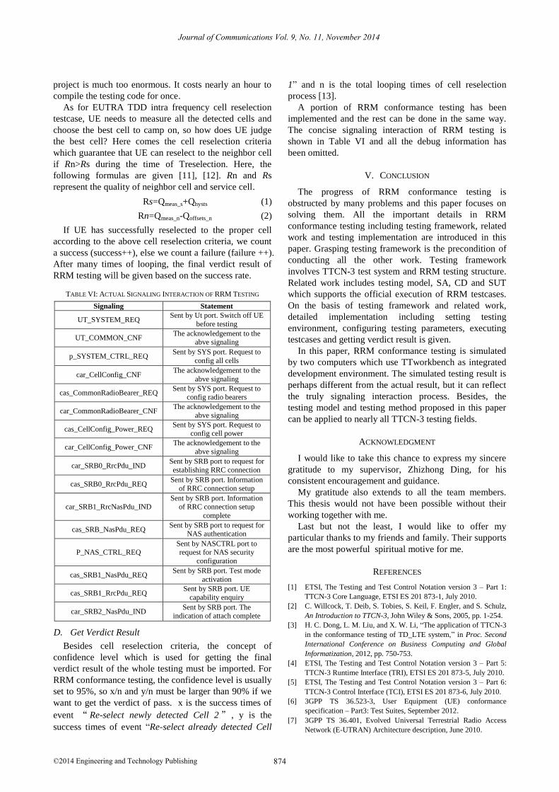
project is much too enormous. It costs nearly an hour to
compile the testing code for once.
As for EUTRA TDD intra frequency cell reselection
testcase, UE needs to measure all the detected cells and
choose the best cell to camp on, so how does UE judge
the best cell? Here comes the cell reselection criteria
which guarantee that UE can reselect to the neighbor cell
if Rn>Rs during the time of Treselection. Here, the
following formulas are given [11], [12]. Rn and Rs
represent the quality of neighbor cell and service cell.
Rs=Qmeas_s+Qhysts (1)
Rn=Qmeas_n-Qoffsets_n (2)
If UE has successfully reselected to the proper cell
according to the above cell reselection criteria, we count
a success (success++), else we count a failure (failure ++).
After many times of looping, the final verdict result of
RRM testing will be given based on the success rate.
TABLE VI: ACTUAL SIGNALING INTERACTION OF RRM TESTING
Signaling Statement
UT_SYSTEM_REQ Sent by Ut port. Switch off UE
before testing
UT_COMMON_CNF The acknowledgement to the
abve signaling
p_SYSTEM_CTRL_REQ Sent by SYS port. Request to
config all cells
car_CellConfig_CNF The acknowledgement to the
abve signaling
cas_CommonRadioBearer_REQ Sent by SYS port. Request to
config radio bearers
car_CommonRadioBearer_CNF The acknowledgement to the
abve signaling
cas_CellConfig_Power_REQ Sent by SYS port. Request to
config cell power
car_CellConfig_Power_CNF The acknowledgement to the
abve signaling
car_SRB0_RrcPdu_IND Sent by SRB port to request for
establishing RRC connection
cas_SRB0_RrcPdu_REQ Sent by SRB port. Information
of RRC connection setup
car_SRB1_RrcNasPdu_IND Sent by SRB port. Information
of RRC connection setup
complete
cas_SRB_NasPdu_REQ Sent by SRB port to request for
NAS authentication
P_NAS_CTRL_REQ Sent by NASCTRL port to request for NAS security
configuration
cas_SRB1_NasPdu_REQ Sent by SRB port. Test mode
activation
cas_SRB1_RrcPdu_REQ Sent by SRB port. UE
capability enquiry
car_SRB2_NasPdu_IND Sent by SRB port. The
indication of attach complete
D. Get Verdict Result
Besides cell reselection criteria, the concept of
confidence level which is used for getting the final
verdict result of the whole testing must be imported. For
RRM conformance testing, the confidence level is usually
set to 95%, so x/n and y/n must be larger than 90% if we
want to get the verdict of pass. x is the success times of
event “Re-select newly detected Cell 2” , y is the
success times of event “Re-select already detected Cell
1” and n is the total looping times of cell reselection
process [13].
A portion of RRM conformance testing has been
implemented and the rest can be done in the same way.
The concise signaling interaction of RRM testing is
shown in Table VI and all the debug information has
been omitted.
V. CONCLUSION
The progress of RRM conformance testing is
obstructed by many problems and this paper focuses on
solving them. All the important details in RRM
conformance testing including testing framework, related
work and testing implementation are introduced in this
paper. Grasping testing framework is the precondition of
conducting all the other work. Testing framework
involves TTCN-3 test system and RRM testing structure.
Related work includes testing model, SA, CD and SUT
which supports the official execution of RRM testcases.
On the basis of testing framework and related work,
detailed implementation including setting testing
environment, configuring testing parameters, executing
testcases and getting verdict result is given.
In this paper, RRM conformance testing is simulated
by two computers which use TTworkbench as integrated
development environment. The simulated testing result is
perhaps different from the actual result, but it can reflect
the truly signaling interaction process. Besides, the
testing model and testing method proposed in this paper
can be applied to nearly all TTCN-3 testing fields.
ACKNOWLEDGMENT
I would like to take this chance to express my sincere
gratitude to my supervisor, Zhizhong Ding, for his
consistent encouragement and guidance.
My gratitude also extends to all the team members.
This thesis would not have been possible without their
working together with me.
Last but not the least, I would like to offer my
particular thanks to my friends and family. Their supports
are the most powerful spiritual motive for me.
REFERENCES
[1] ETSI, The Testing and Test Control Notation version 3 – Part 1:
TTCN-3 Core Language, ETSI ES 201 873-1, July 2010.
[2] C. Willcock, T. Deib, S. Tobies, S. Keil, F. Engler, and S. Schulz,
An Introduction to TTCN-3, John Wiley & Sons, 2005, pp. 1-254.
[3] H. C. Dong, L. M. Liu, and X. W. Li, “The application of TTCN-3
in the conformance testing of TD_LTE system,” in Proc. Second
International Conference on Business Computing and Global
Informatization, 2012, pp. 750-753.
[4] ETSI, The Testing and Test Control Notation version 3 – Part 5:
TTCN-3 Runtime Interface (TRI), ETSI ES 201 873-5, July 2010.
[5] ETSI, The Testing and Test Control Notation version 3 – Part 6:
TTCN-3 Control Interface (TCI), ETSI ES 201 873-6, July 2010.
[6] 3GPP TS 36.523-3, User Equipment (UE) conformance
specification – Part3: Test Suites, September 2012.
[7] 3GPP TS 36.401, Evolved Universal Terrestrial Radio Access
Network (E-UTRAN) Architecture description, June 2010.
Journal of Communications Vol. 9, No. 11, November 2014
©2014 Engineering and Technology Publishing 874
[8] S. Sesia, I. Toufik, and M. Baker, LTE – The UMTS Long Term
Evolution From Theory to Practice, John Wiley & Sons, 2009, pp.
21-110.
[9] 3GPP TS 24.301, Non-Access-Stratum (NAS) Protocol for
Evolved Packet System (EPS), March 2013.
[10] 3GPP TS 36.508, Evolved Universal Terrestrial Radio Access (E-
UTRA) and Evolved Packet Core (EPC) Common test
environments for User Equipment (UE) conformance testing, June
2012.
[11] 3GPP TS 36.521-3, User Equipment (UE) conformance
specification – Part3: Radio Resource Management (RRM)
Conformance Testing, June 2012.
[12] 3GPP TS 36.304, Evolved Universal Terrestrial Radio Access (E-
UTRA) User Equipment (UE) procedures in idle mode, June
2012.
[13] J. H. Li, Y. Q. Cao, and Y. Y. Sun, “The judgement and
implementation of confidence level in RRM teminal
conformance testing (in Chinese),” Telecommunications Network
Technology, April 2011.
Ding-Liang Wang was born in Anhui
Province, China, in 1990. He received his
B.E. degree in Communication Engineering
from Hefei University of Technology, Anhui
province, China. He is currently working
toward Master’s degree at Hefei University of
Technology. His research interests include
protocol conformance testing and wireless
communicaiton.
Zhizhong Ding received his B.E degree in
Radio Communications from Nanjing
University of Aeronautics and Astronautics,
Nanjing, China, Master’s degree in circuit and
system from Hefei University of Technoloy,
Hefei, China, and Ph.D. in Information and
communication engineering from University
of Science and Technology of China. He
currently is a Professor with the Department
of Communication Engineering and with the Institute of
Communications and Information Systems, Hefei University of
Technology. His research interests include wireless communications,
network communications and information theory.
Yin Chen was born in Jiangxi Province,
China. He received his B.S degree in
Information and Computing Science from
Hefei University of Technology, Anhui
province, China. He is currently working
toward Master’s degree at Hefei University of
Technology. His research interests include
protocol conformance testing and wireless
networks.
You-Nan Duan Mr. Younan Duan received
his B.E degree in Communication
Engineering from Huaibei Normal University,
Anhui province, China. He is currently
working toward Master`s degree at Hefei
University of Technology. His research
interests include protocol conformance testing
based on TTCN-3, and hardware
implementation of 802.11p protocol.
Journal of Communications Vol. 9, No. 11, November 2014
©2014 Engineering and Technology Publishing 875


![LTE-A Base Station Receiver Tests - Rohde & Schwarz...The LTE-A conformance tests for base stations (eNodeB) are defined in 3GPP TS 36.141 Release 14 [1] and include transmitter (Tx),](https://img.pdfslide.us/doc/110x75/5f0bf4fb7e708231d4330dac/lte-a-base-station-receiver-tests-rohde-schwarz-the-lte-a-conformance.jpg)