Embed Size (px)
Citation preview
1
LTE – Long Term Evolution
Introduction
2
Outline Evolution and Adoption Features Architecture Radio Interface Overview of Protocols and Channels LTE-Advanced
3
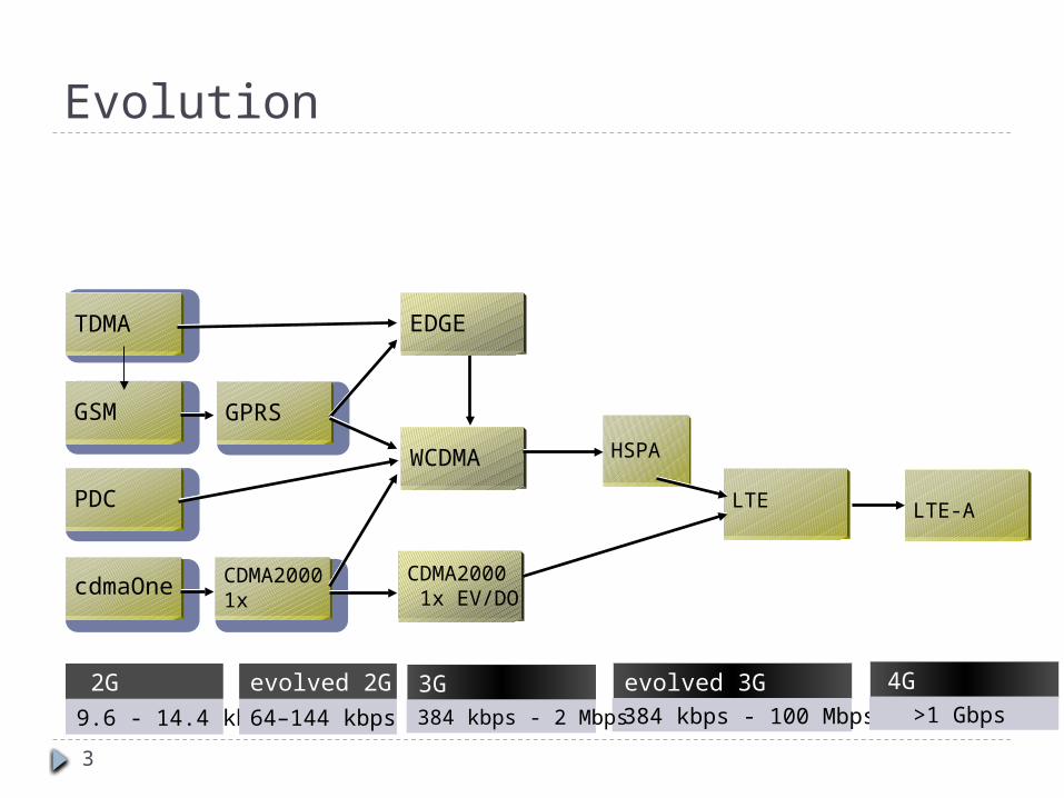
Evolution
cdmaOne
GSM
TDMA
PDC
2G
9.6 - 14.4 kbps
CDMA2000 1x
GPRS
evolved 2G
64–144 kbps
evolved 3G384 kbps - 100 Mbps
EDGE
WCDMA
CDMA2000 1x EV/DO
3G384 kbps - 2 Mbps
4G>1 Gbps
HSPA
LTE LTE-A
4
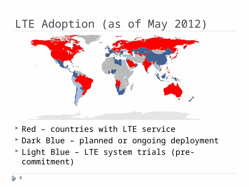
LTE Adoption (as of May 2012)
Red – countries with LTE service Dark Blue – planned or ongoing deployment Light Blue – LTE system trials (pre-commitment)
5
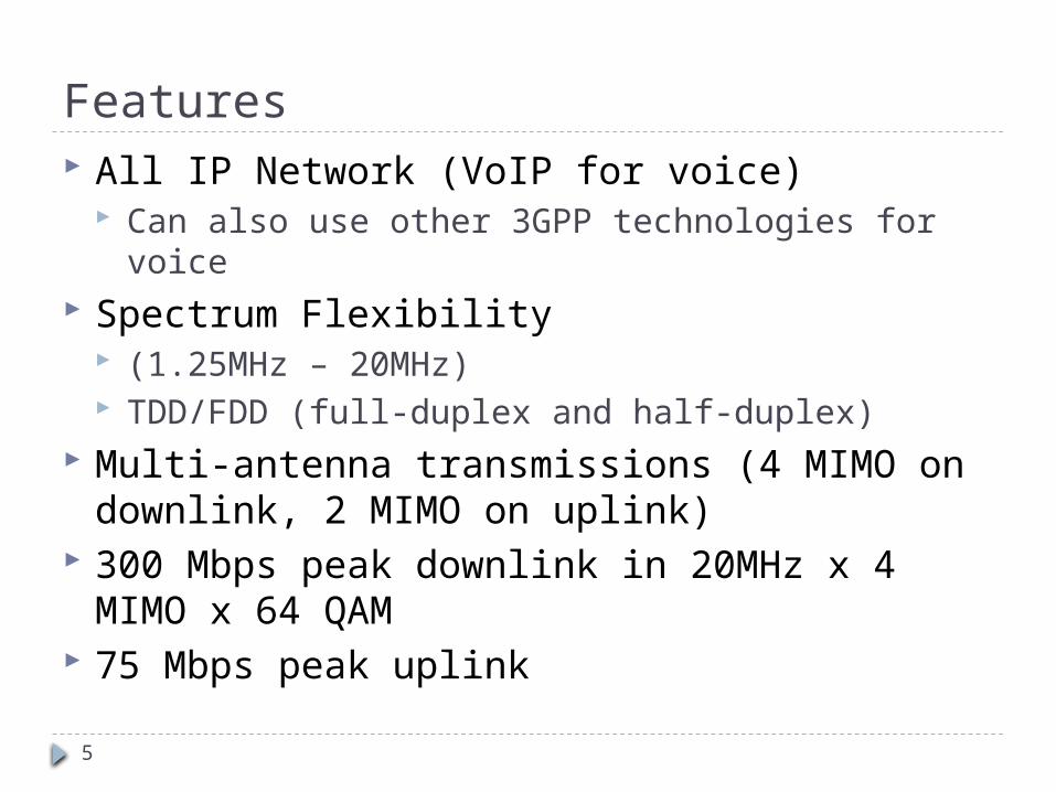
Features All IP Network (VoIP for voice)
Can also use other 3GPP technologies for voice Spectrum Flexibility
(1.25MHz – 20MHz) TDD/FDD (full-duplex and half-duplex)
Multi-antenna transmissions (4 MIMO on downlink, 2 MIMO on uplink)
300 Mbps peak downlink in 20MHz x 4 MIMO x 64 QAM
75 Mbps peak uplink
6
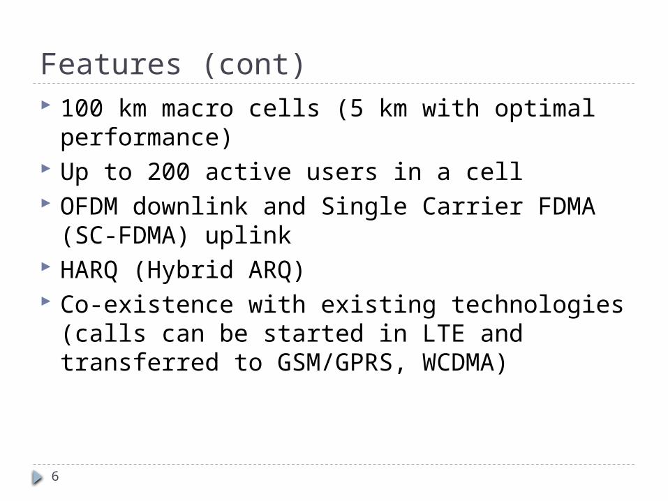
Features (cont) 100 km macro cells (5 km with optimal
performance) Up to 200 active users in a cell OFDM downlink and Single Carrier FDMA (SC-
FDMA) uplink HARQ (Hybrid ARQ) Co-existence with existing technologies (calls
can be started in LTE and transferred to GSM/GPRS, WCDMA)
7
Architecture
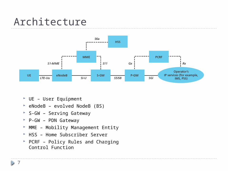
UE – User Equipment eNodeB – evolved NodeB (BS) S-GW – Serving Gateway P-GW – PDN Gateway MME – Mobility Management Entity HSS – Home Subscriber Server PCRF – Policy Rules and Charging Control
Function
8
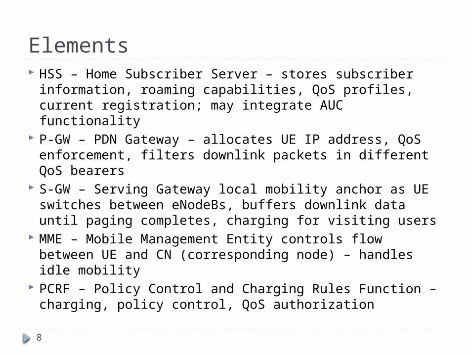
Elements HSS – Home Subscriber Server – stores subscriber
information, roaming capabilities, QoS profiles, current registration; may integrate AUC functionality
P-GW – PDN Gateway – allocates UE IP address, QoS enforcement, filters downlink packets in different QoS bearers
S-GW – Serving Gateway local mobility anchor as UE switches between eNodeBs, buffers downlink data until paging completes, charging for visiting users
MME – Mobile Management Entity controls flow between UE and CN (corresponding node) – handles idle mobility
PCRF – Policy Control and Charging Rules Function – charging, policy control, QoS authorization
9
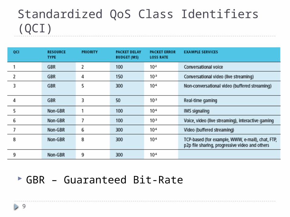
Standardized QoS Class Identifiers (QCI)
GBR – Guaranteed Bit-Rate
10
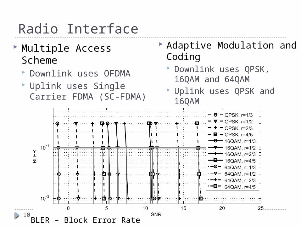
Radio Interface Adaptive Modulation and
Coding Downlink uses QPSK,
16QAM and 64QAM Uplink uses QPSK and
16QAM
Multiple Access Scheme Downlink uses OFDMA Uplink uses Single Carrier
FDMA (SC-FDMA)
BLER – Block Error Rate
11
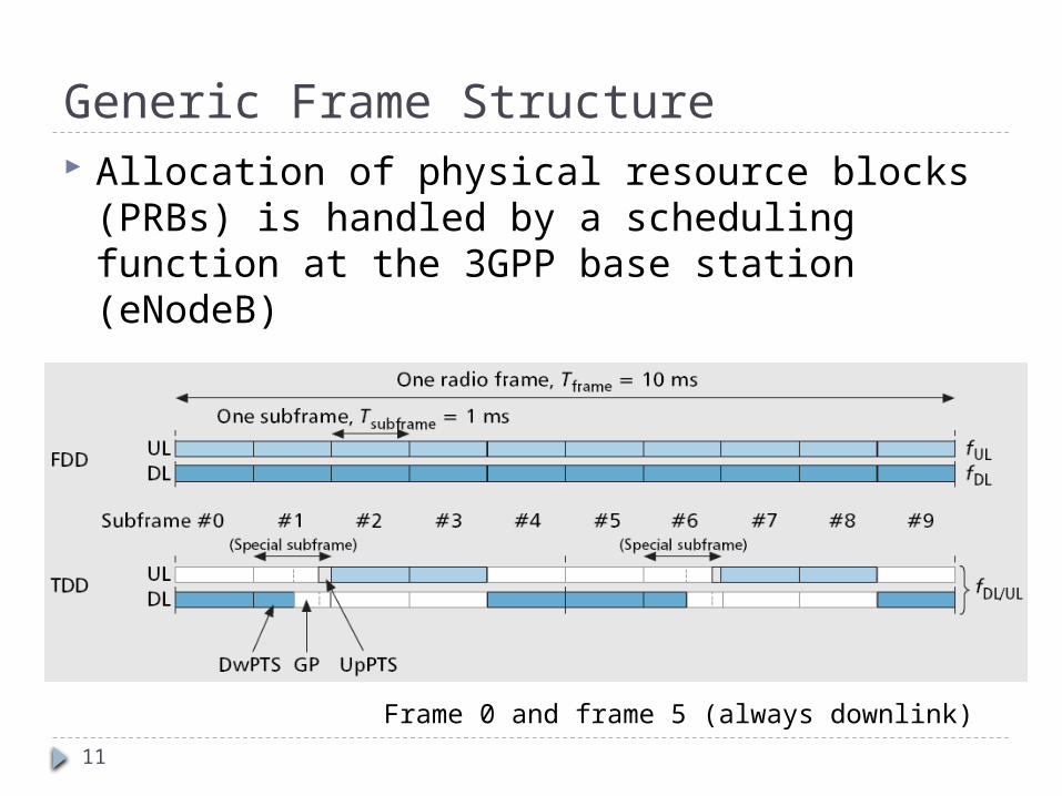
Generic Frame Structure Allocation of physical resource blocks (PRBs) is
handled by a scheduling function at the 3GPP base station (eNodeB)
Frame 0 and frame 5 (always downlink)
12
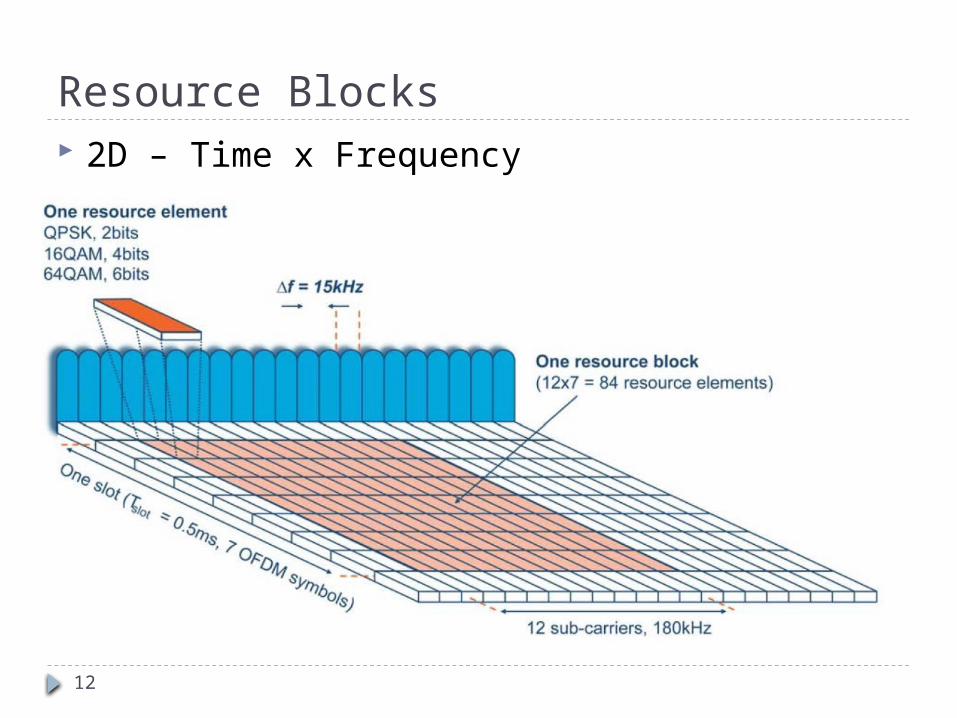
Resource Blocks 2D – Time x Frequency
13
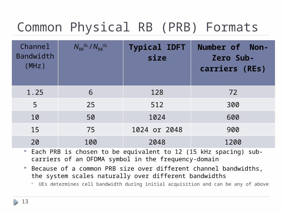
Common Physical RB (PRB) Formats
PRBs are mapped onto contiguous OFDMA/SC-FDMA symbols in the time-domain (6 or 7)
Each PRB is chosen to be equivalent to 12 (15 kHz spacing) sub-carriers of an OFDMA symbol in the frequency-domain
Because of a common PRB size over different channel bandwidths, the system scales naturally over different bandwidths UEs determines cell bandwidth during initial acquisition and can be any of above
Channel Bandwidth
(MHz)
NRBDL/NRB
UL Typical IDFT size Number of Non-Zero Sub-carriers (REs)
1.25 6 128 72
5 25 512 300
10 50 1024 600
15 75 1024 or 2048 900
20 100 2048 1200
14
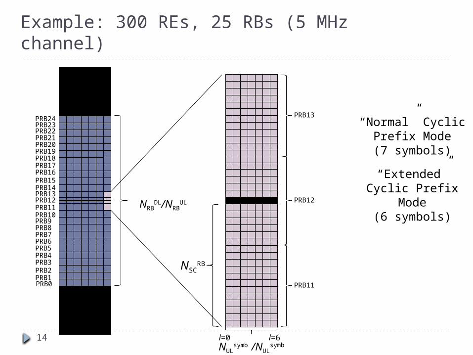
Example: 300 REs, 25 RBs (5 MHz channel)
PRB0PRB1PRB2PRB3PRB4PRB5PRB6PRB7PRB8PRB9PRB10PRB11PRB12PRB13PRB14PRB15PRB16PRB17PRB18PRB19PRB20PRB21PRB22PRB23PRB24 PRB13
PRB12
PRB11
“Normal” Cyclic Prefix Mode(7 symbols)
l=0 l=6
NSCRB
NRBDL/NRB
UL
NULsymb /NUL
symb
“Extended” Cyclic Prefix Mode(6 symbols)
15
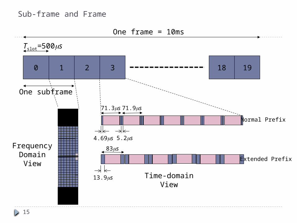
Sub-frame and Frame
0 1 2 3 18 19
One frame = 10ms
One subframe
Tslot=500ms
FrequencyDomain
View
Time-domainView
Normal Prefix
Extended Prefix
83ms
13.9ms
71.3ms 71.9ms
4.69ms 5.2ms
16
OFDMLTE uses OFDM for the downlink – that is, from the base station to the terminal. OFDM meets the LTE requirement for spectrum flexibility and enables cost-efficient solutions for very wide carriers with high peak rates. OFDM uses a large number of narrow sub-carriers for multi-carrier transmission.
The basic LTE downlink physical resource can be seen as a time-frequency grid. In the frequency domain, the spacing between the subcarriers, Δf, is 15kHz. In addition, the OFDM symbol duration time is 1/Δf + cyclic prefix. The cyclic prefix is used to maintain orthogonality between the sub-carriers even for a time-dispersive radio channel.
One resource element carries QPSK, 16QAM or 64QAM. With 64QAM, each resource element carries six bits.
The OFDM symbols are grouped into resource blocks. The resource blocks have a total size of 180kHz in the frequency domain and 0.5ms in the time domain. Each 1ms Transmission Time Interval (TTI) consists of two slots (Tslot).
In E-UTRA, downlink modulation schemes QPSK, 16QAM, and 64QAM are available.
17
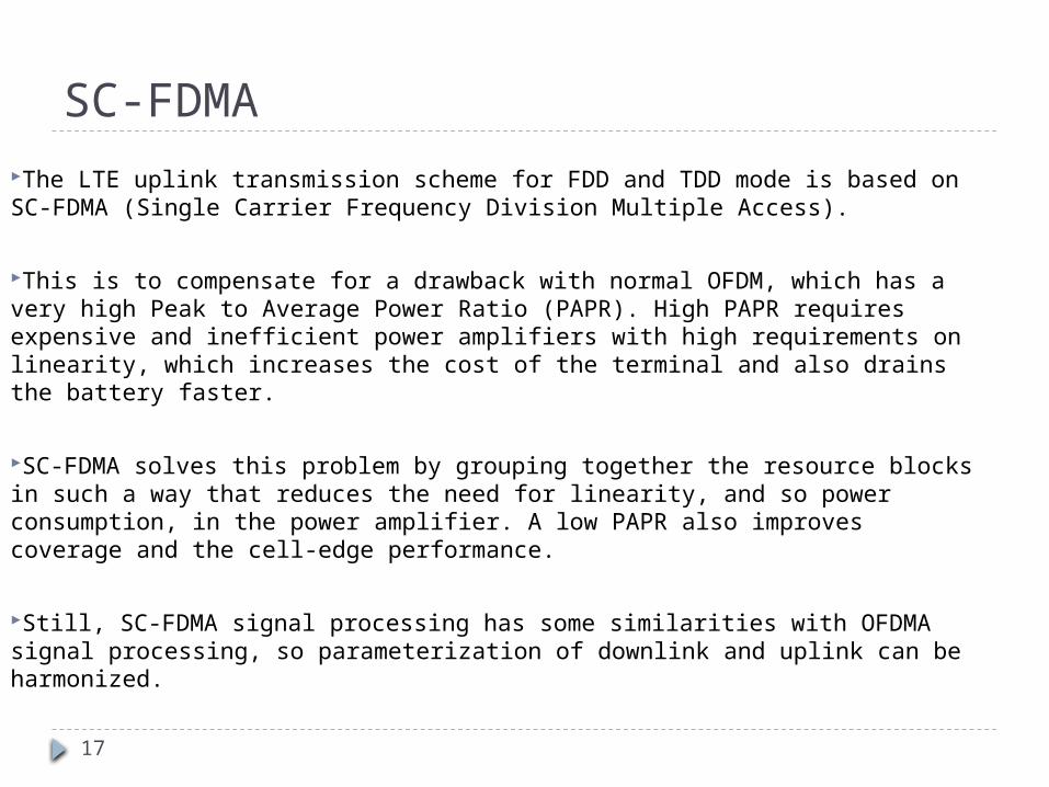
SC-FDMAThe LTE uplink transmission scheme for FDD and TDD mode is based on SC-FDMA (Single Carrier Frequency Division Multiple Access).
This is to compensate for a drawback with normal OFDM, which has a very high Peak to Average Power Ratio (PAPR). High PAPR requires expensive and inefficient power amplifiers with high requirements on linearity, which increases the cost of the terminal and also drains the battery faster.
SC-FDMA solves this problem by grouping together the resource blocks in such a way that reduces the need for linearity, and so power consumption, in the power amplifier. A low PAPR also improves coverage and the cell-edge performance.
Still, SC-FDMA signal processing has some similarities with OFDMA signal processing, so parameterization of downlink and uplink can be harmonized.
18
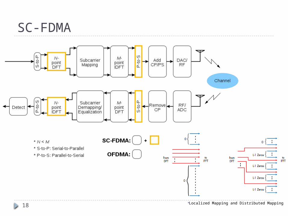
SC-FDMA
Localized Mapping and Distributed Mapping
19
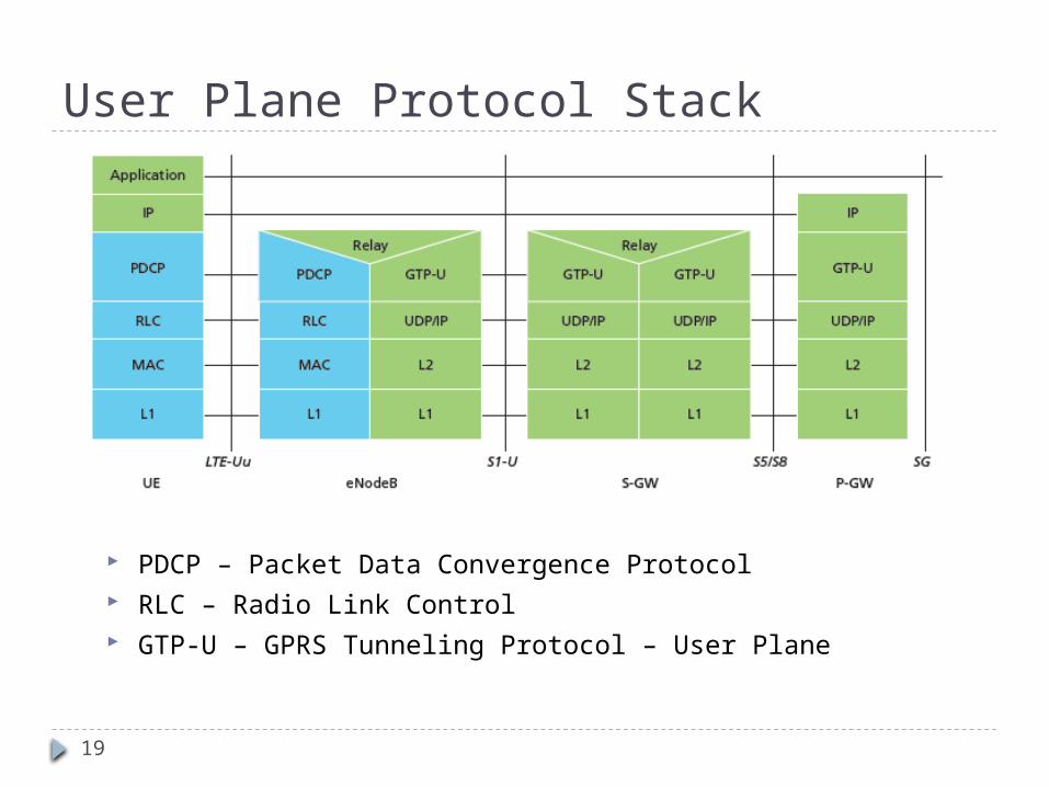
User Plane Protocol Stack
PDCP – Packet Data Convergence Protocol RLC – Radio Link Control GTP-U – GPRS Tunneling Protocol – User Plane
20
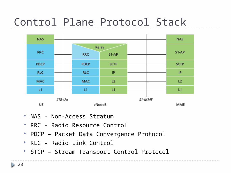
Control Plane Protocol Stack
NAS – Non-Access Stratum RRC – Radio Resource Control PDCP – Packet Data Convergence Protocol RLC – Radio Link Control STCP – Stream Transport Control Protocol
21
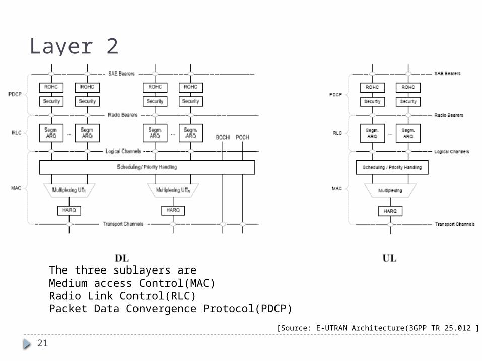
Layer 2
The three sublayers are Medium access Control(MAC)Radio Link Control(RLC)Packet Data Convergence Protocol(PDCP)
[Source: E-UTRAN Architecture(3GPP TR 25.012 ]
22
Layer 2
MAC (media access control) protocol handles uplink and downlink scheduling and HARQ signaling. Performs mapping between logical and transport channels.
RLC (radio link control) protocol focuses on lossless transmission of data. In-sequence delivery of data. Provides 3 different reliability modes for data transport. They are
Acknowledged Mode (AM)-appropriate for non-RT (NRT) services such as file downloads.
Unacknowledged Mode (UM)-suitable for transport of Real Time (RT) services because such services are delay sensitive and cannot wait for retransmissions
Transparent Mode (TM)-used when the PDU sizes are known a priori such as for broadcasting system information.
23
Layer 2
PDCP (packet data convergence protocol) handles the header compression and security
functions of the radio interface
RRC (radio resource control) protocol handles radio bearer setup active mode mobility management
Broadcasts of system information, while the NAS protocols deal with idle mode mobility management and service setup
24
Three Types of Channels in LTE In GMS only logical and physical In LTE:
Logical Channels – what type of information is transported Control x 5 Traffic x 2
Transport Channels – how is the information transported Modulation, coding, antenna port
Physical Channels – where is the information transported What resource blocks are allocated
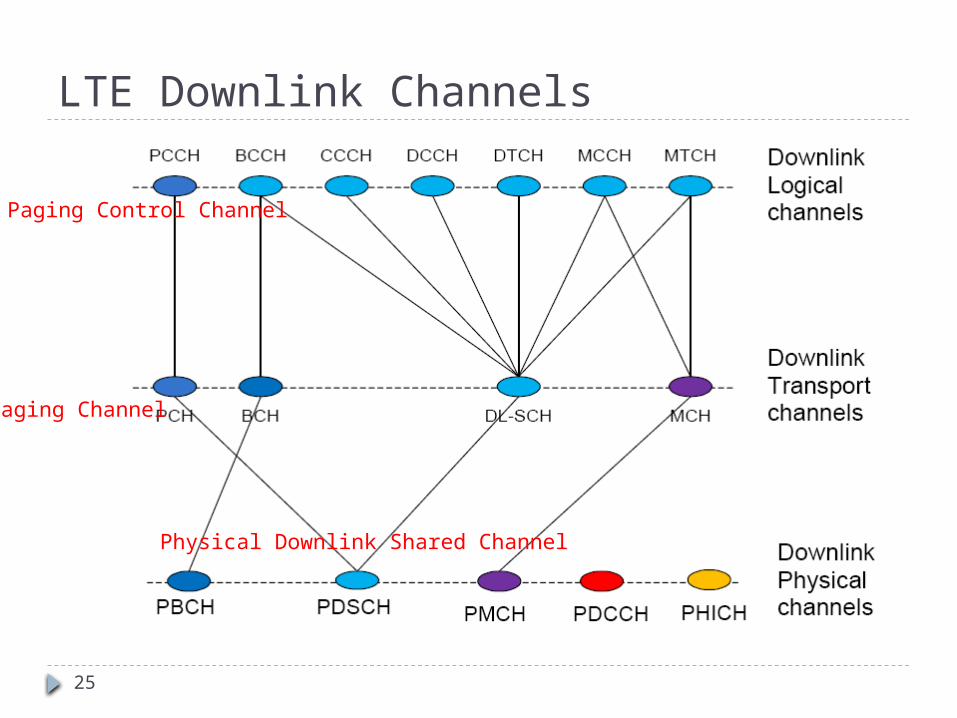
25
LTE Downlink Channels
Paging Channel
Paging Control Channel
Physical Downlink Shared Channel
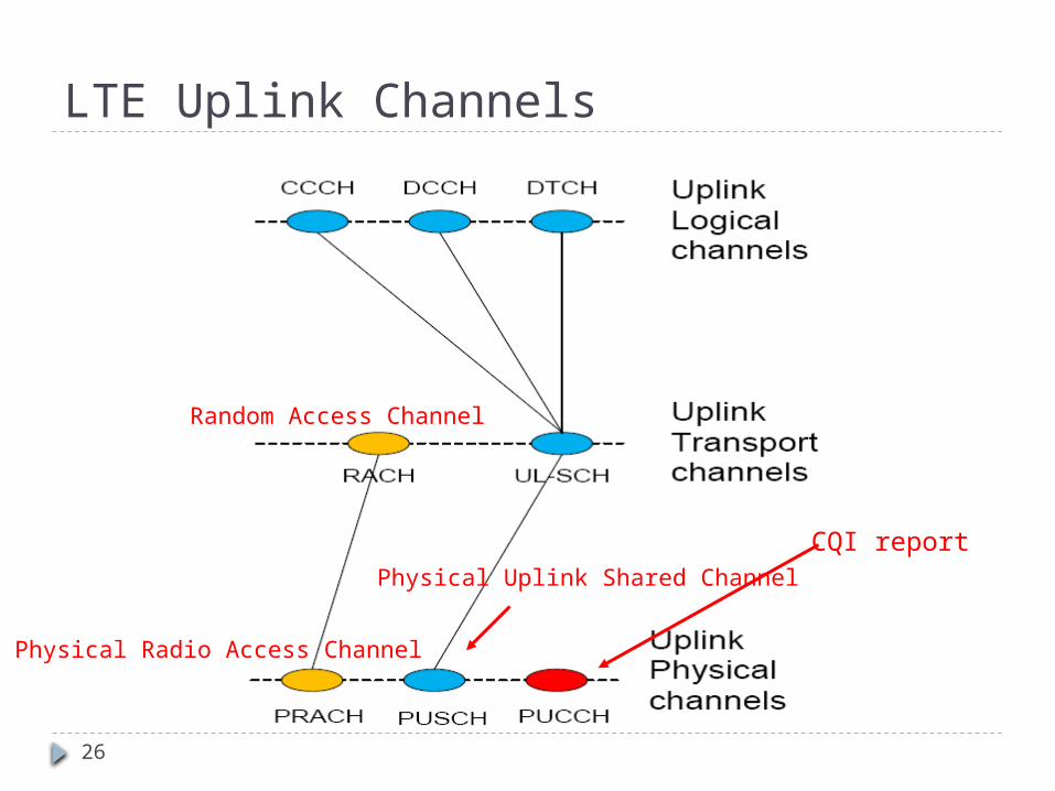
26
LTE Uplink Channels
Random Access Channel
Physical Radio Access Channel
Physical Uplink Shared Channel
CQI report
27
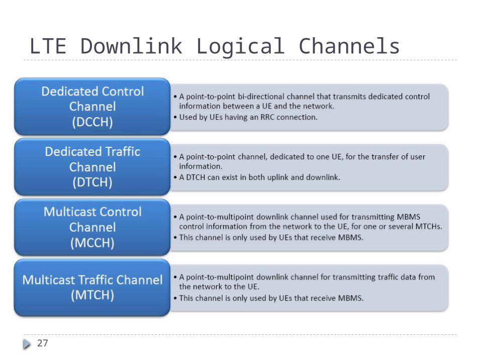
LTE Downlink Logical Channels
28
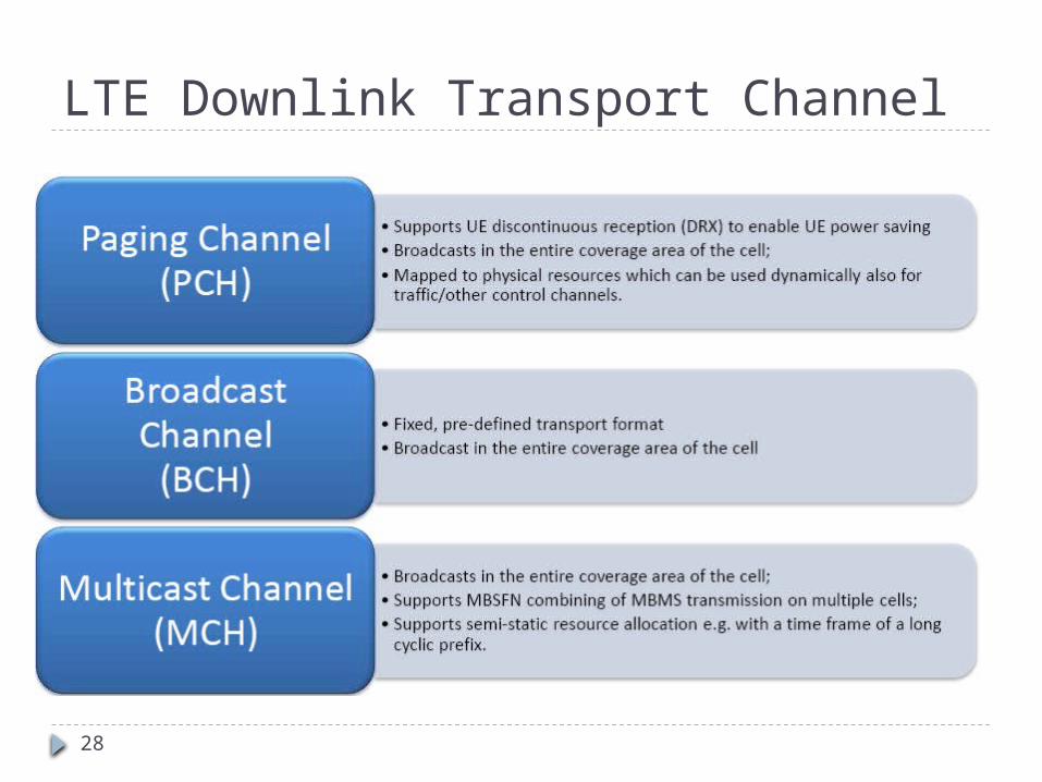
LTE Downlink Transport Channel
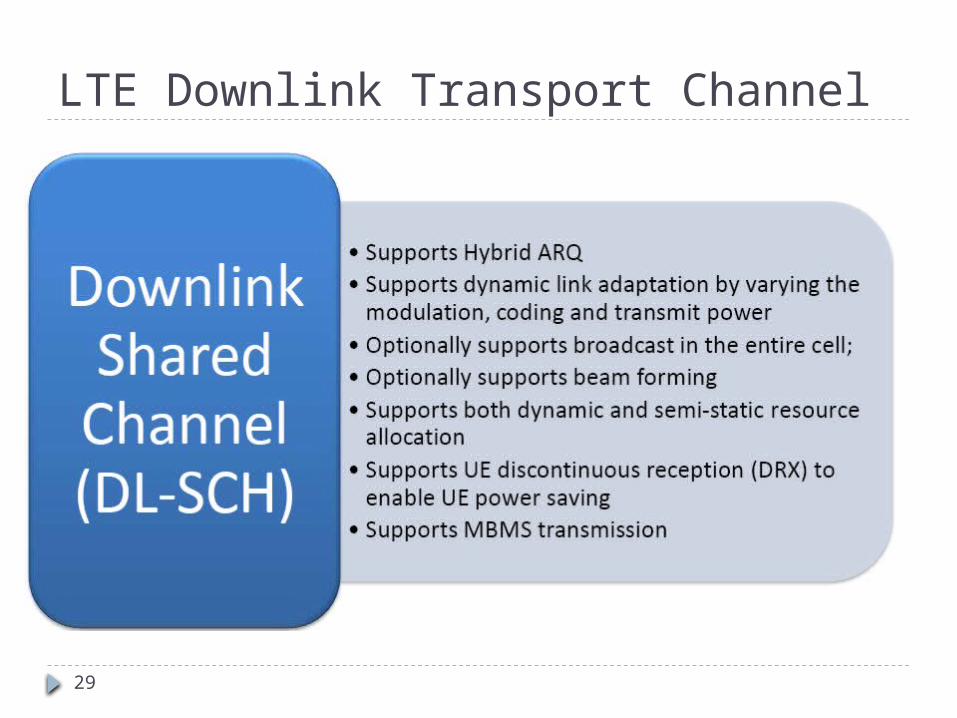
29
LTE Downlink Transport Channel
30
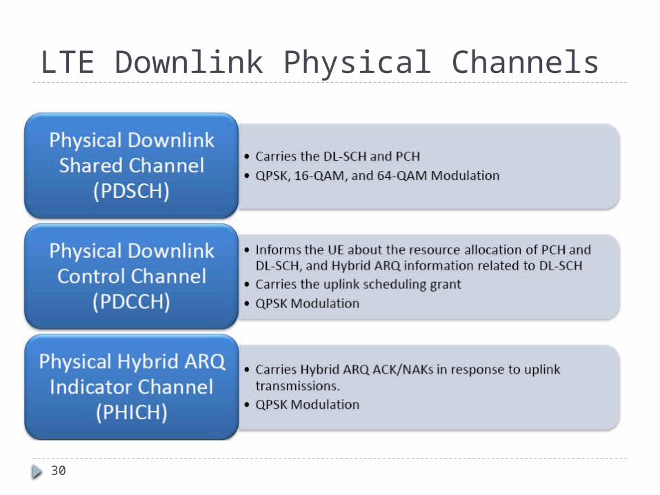
LTE Downlink Physical Channels
31
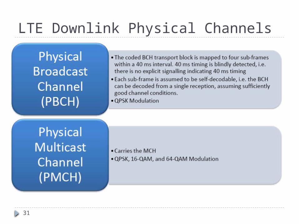
LTE Downlink Physical Channels
32
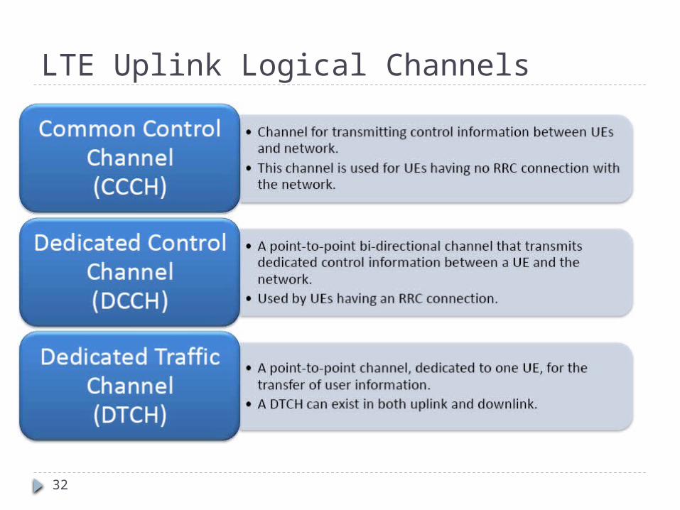
LTE Uplink Logical Channels
33
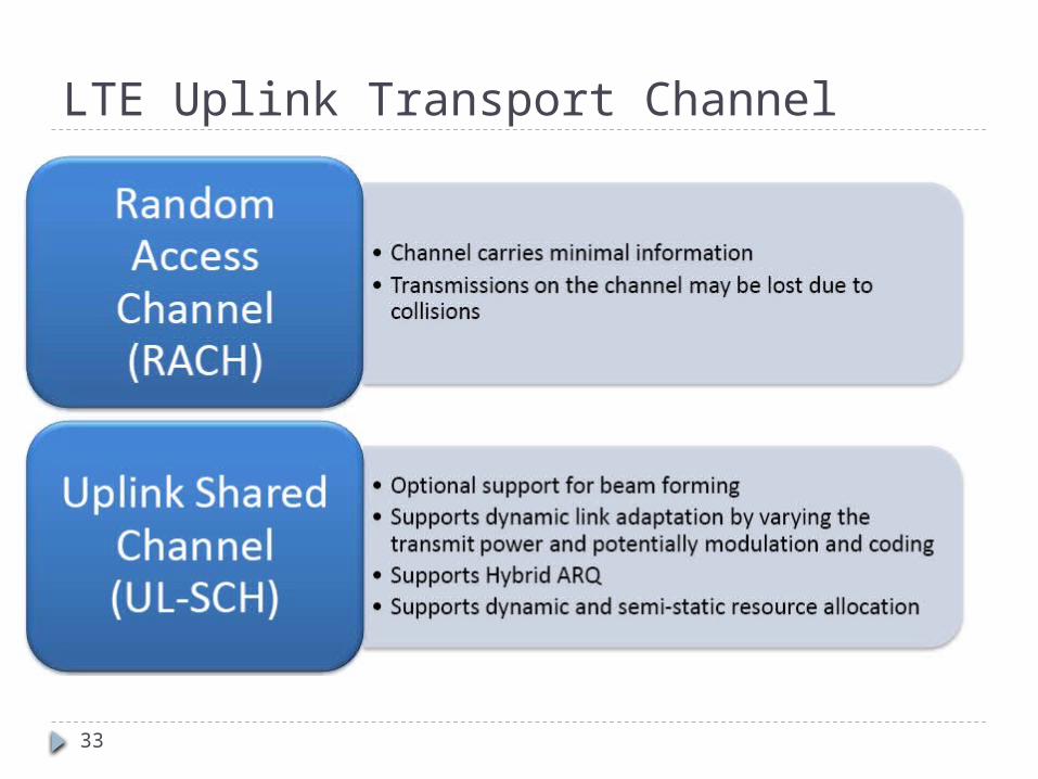
LTE Uplink Transport Channel
34
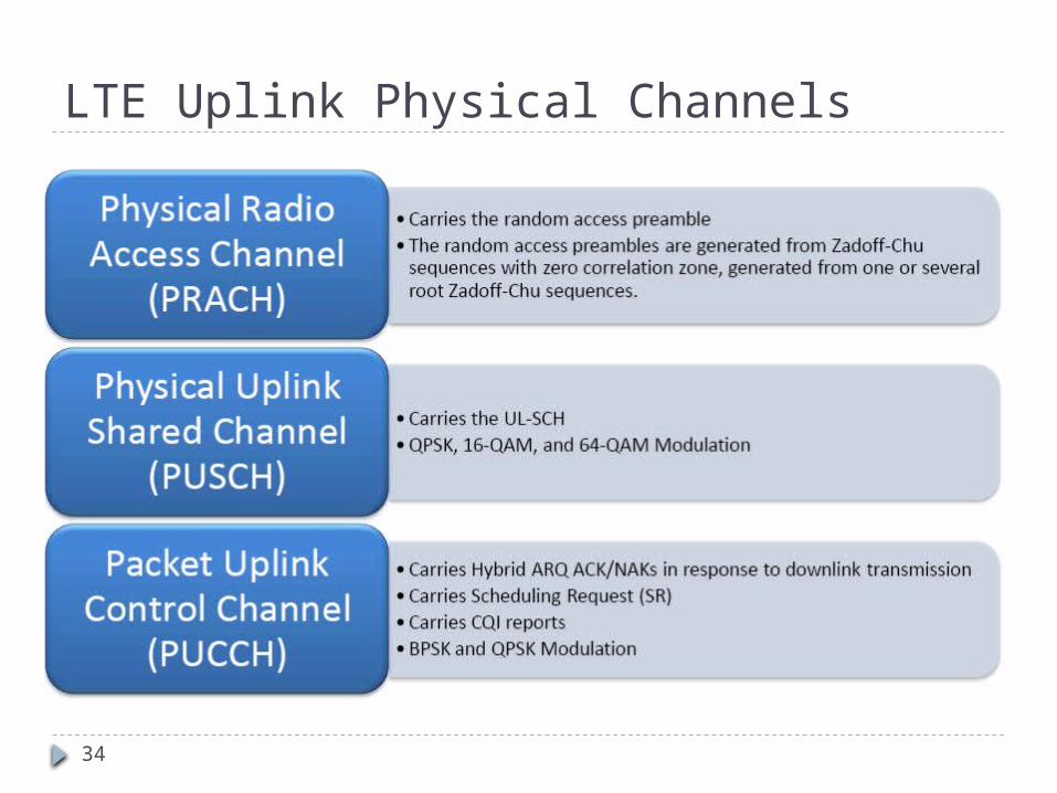
LTE Uplink Physical Channels
35
LTE Advanced Features
100MHz Bandwidth supported 1Gbps DL, 500 Mbps UL Carrier Aggregation Relays
36
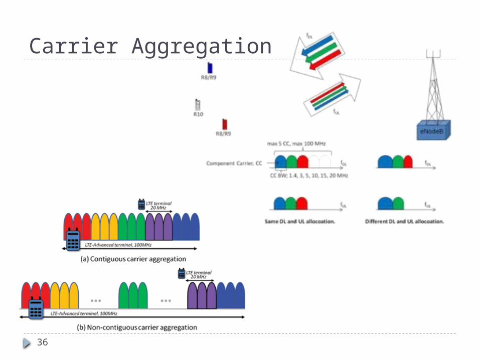
Carrier Aggregation
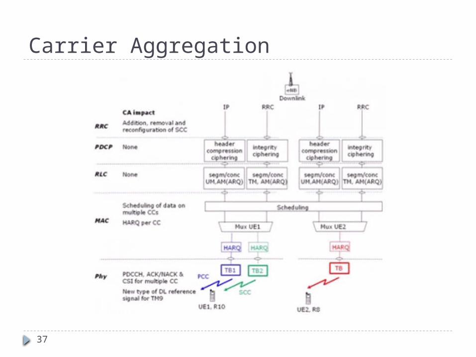
37
Carrier Aggregation
38
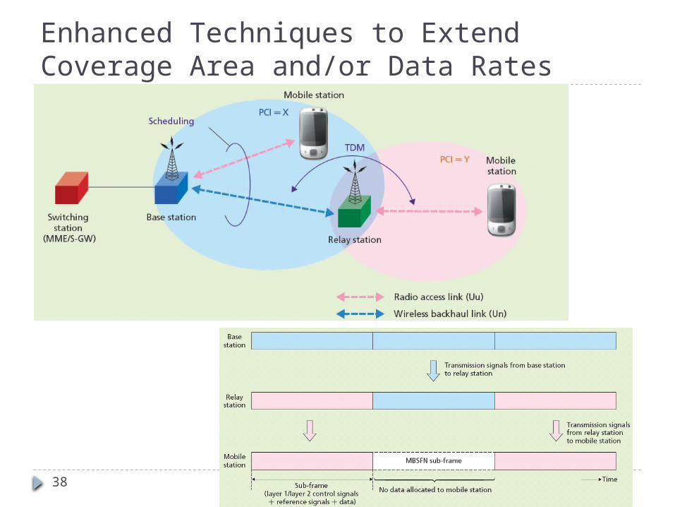
Enhanced Techniques to Extend Coverage Area and/or Data Rates
39
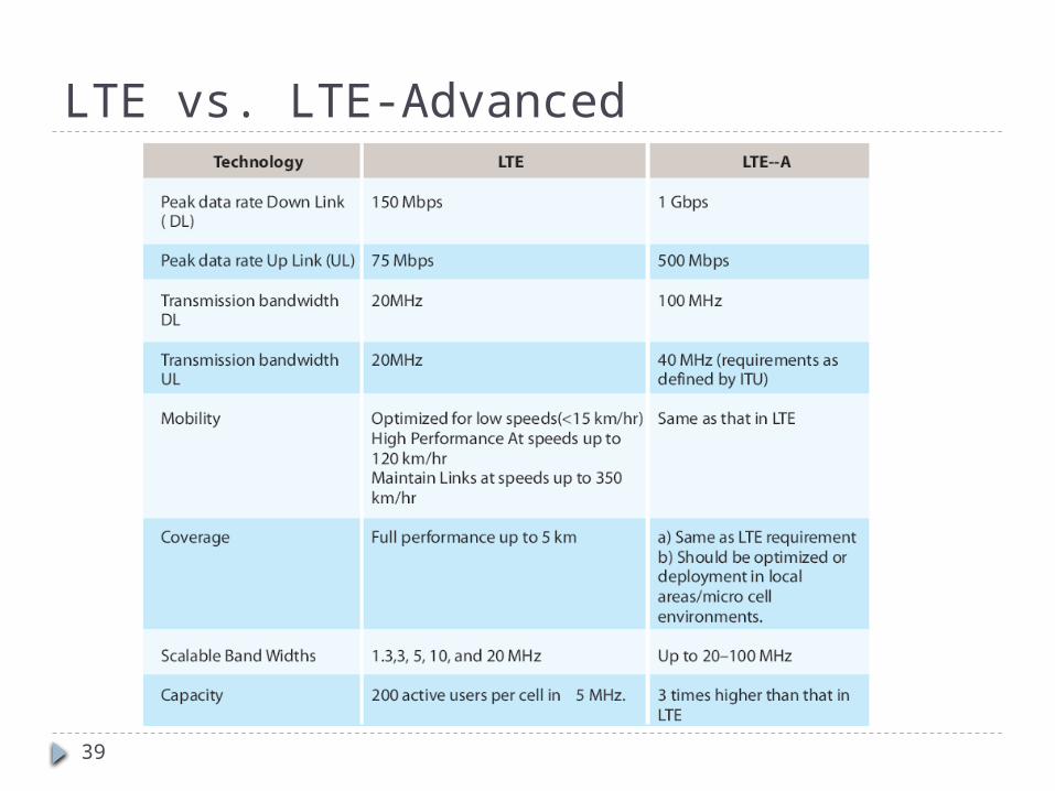
LTE vs. LTE-Advanced