Embed Size (px)
Citation preview
LTE Architecture
KANNAN MJTO(3G)
EPC
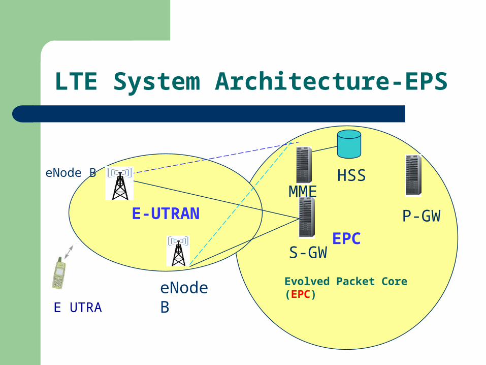
LTE System Architecture-EPS
E-UTRAN
eNode B
eNode B
P-GW
E UTRA
S-GW
HSSMME
Evolved Packet Core (EPC)
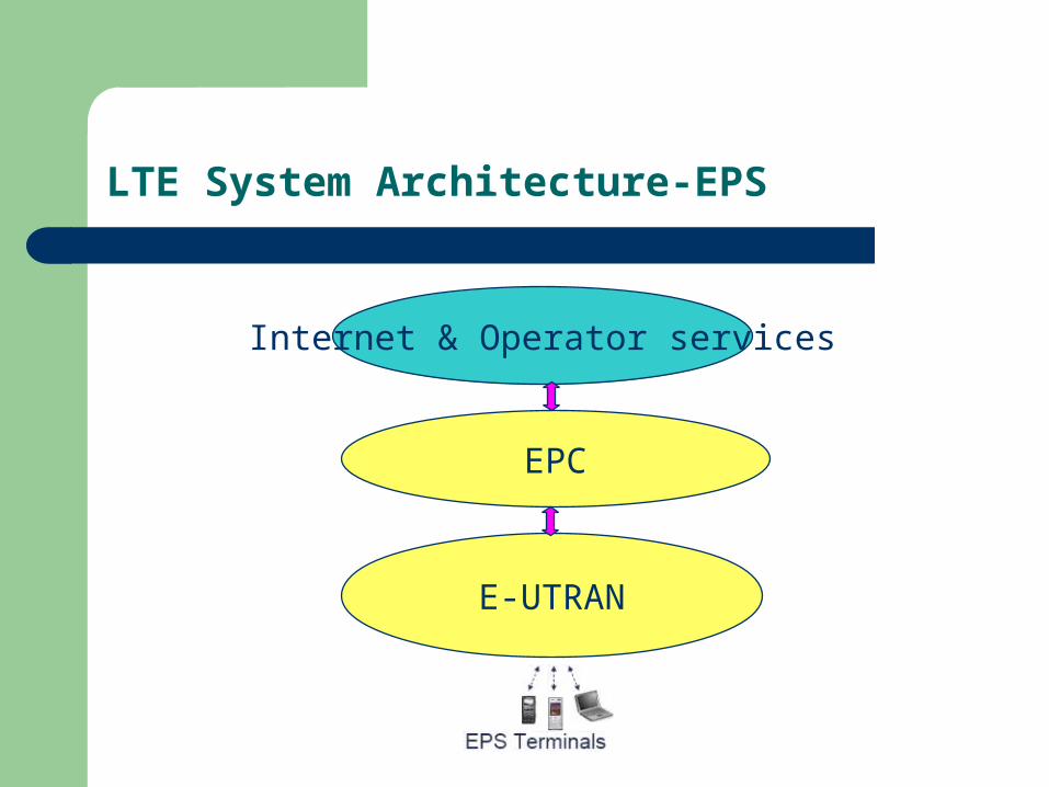
LTE System Architecture-EPS
Internet & Operator services
EPC
E-UTRAN
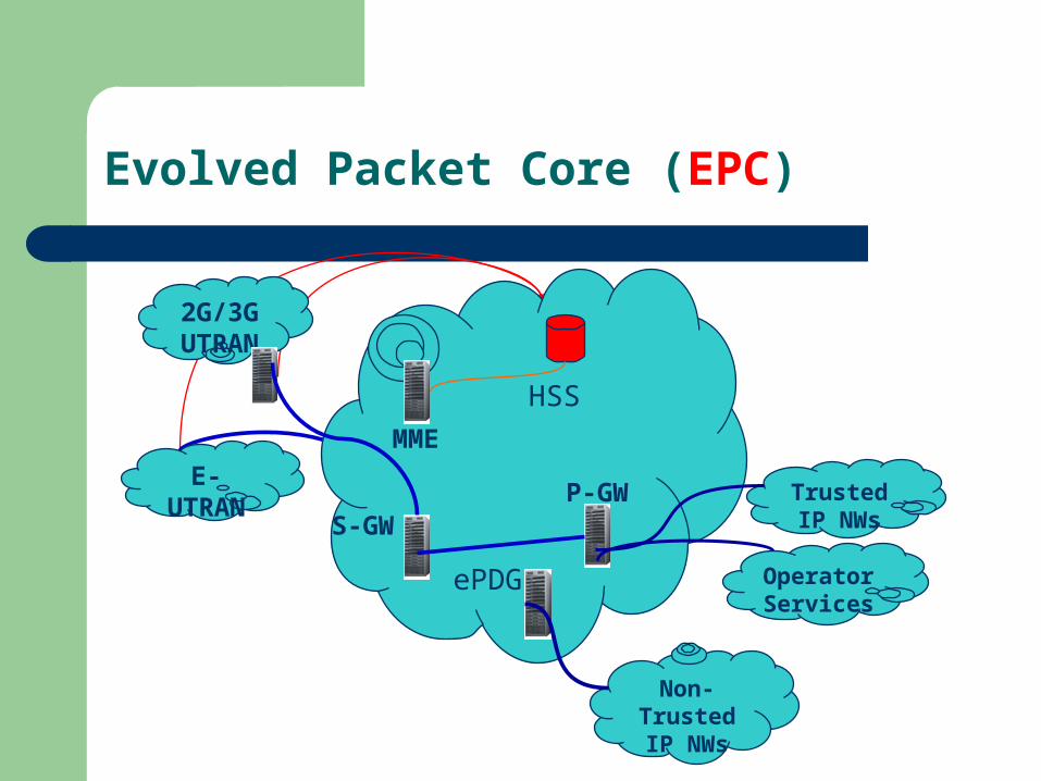
Evolved Packet Core (EPC)
2G/3G UTRAN
E- UTRAN
Operator Services
S-GWP-GW
HSS
Trusted IP NWs
Non-Trusted IP
NWs
ePDG
MME
EPC –Home Subscriber Server
Master subscriber database Stores user related information like, subscription
parameters, user identification, service profile, user location etc
Generates security related information It can be treated as an “upgraded HLR” with GSM, GPRS,
LTE and IMS information
EPC –Mobility Management Entity
Main control node Handles the control plane signaling Idle mode UE tracking Bearer activation / de-activation Choice of SGW and PGW for a UE Mobility anchoring Interacting with HSS to authenticate user Provides temporary identities for UEs Paging procedure Coordinating LI
EPC –Serving GateWay
A data plane element
An interface for the data packet network at the E-UTRAN.
The SGW maintains the data paths between the eNodeBs and the PDN Gateways
Routes user data packets between E-UTRAN and P-GW
When UEs move across areas served by different eNodeBs, the SGW serves as a mobility anchor ensuring that the data path is maintained
EPC –Packet Data Network GateWay
A data plane element
provides connectivity for the UE to external packet data networks
The UE may have connectivity with more than one PGW for accessing multiple PDNs
Charging
QoS control
IP address allocation
EPC – evolved PDG (ePDG)
Gateway used for Interworking with non trusted non
3GPP IP access systems
Provides some additional security mechanisms
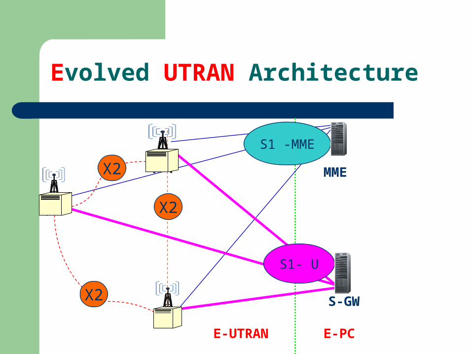
Evolved UTRAN Architecture
E-UTRAN E-PC
X2
X2
X2
MME
S-GW
S1 -MME
S1- U
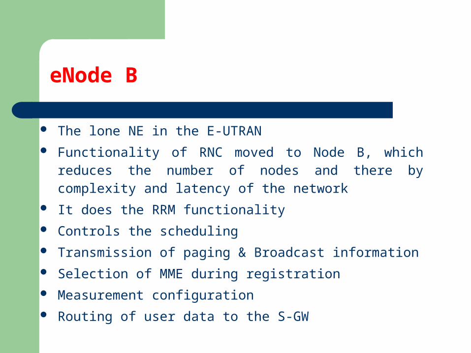
eNode B
The lone NE in the E-UTRAN Functionality of RNC moved to Node B, which reduces the number
of nodes and there by complexity and latency of the network It does the RRM functionality Controls the scheduling Transmission of paging & Broadcast information Selection of MME during registration Measurement configuration Routing of user data to the S-GW
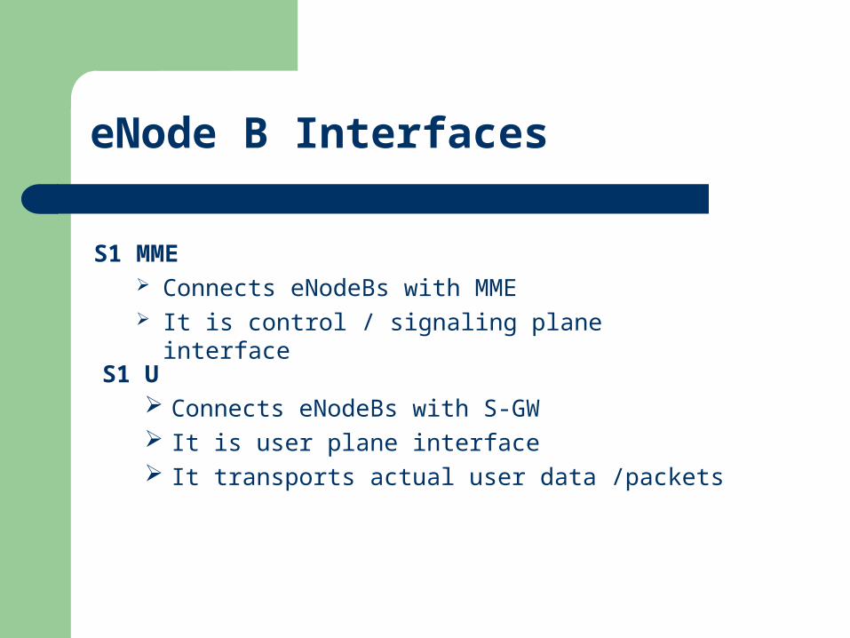
eNode B Interfaces
S1 MME Connects eNodeBs with MME It is control / signaling plane interface
S1 U Connects eNodeBs with S-GW It is user plane interface It transports actual user data /packets
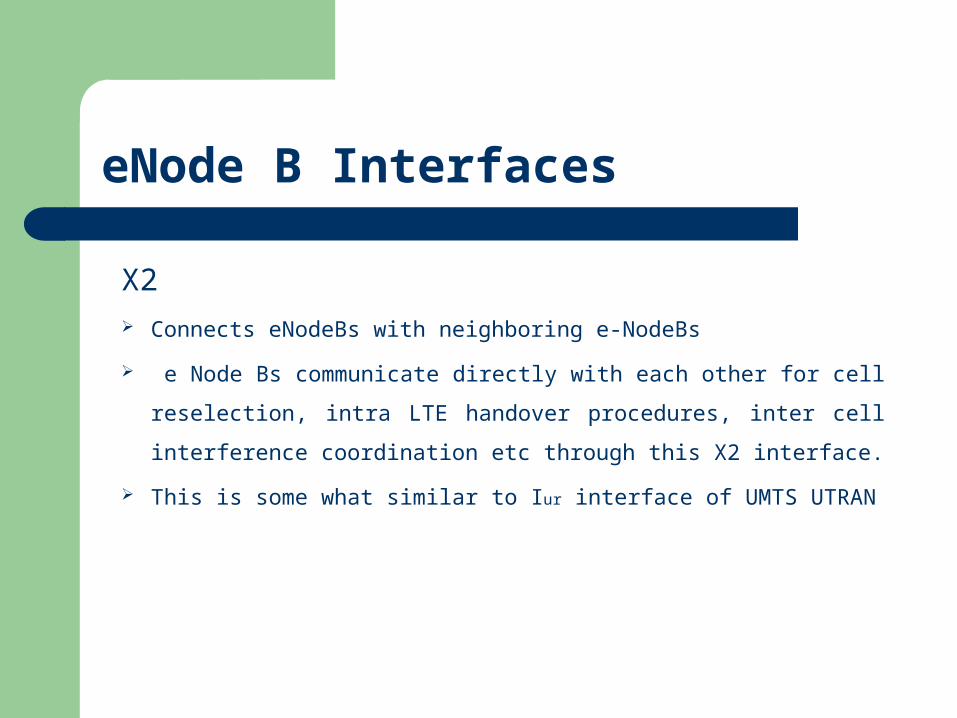
eNode B Interfaces
X2 Connects eNodeBs with neighboring e-NodeBs
e Node Bs communicate directly with each other for cell
reselection, intra LTE handover procedures, inter cell interference
coordination etc through this X2 interface.
This is some what similar to Iur interface of UMTS UTRAN
Advantages
Reduce Capax and Opex
Reduce Investment Risk
Quick responses to market opportunities
Improve users’ experience
Convergence Equipment Level
Site Level Operation Level
LTE in the coming future
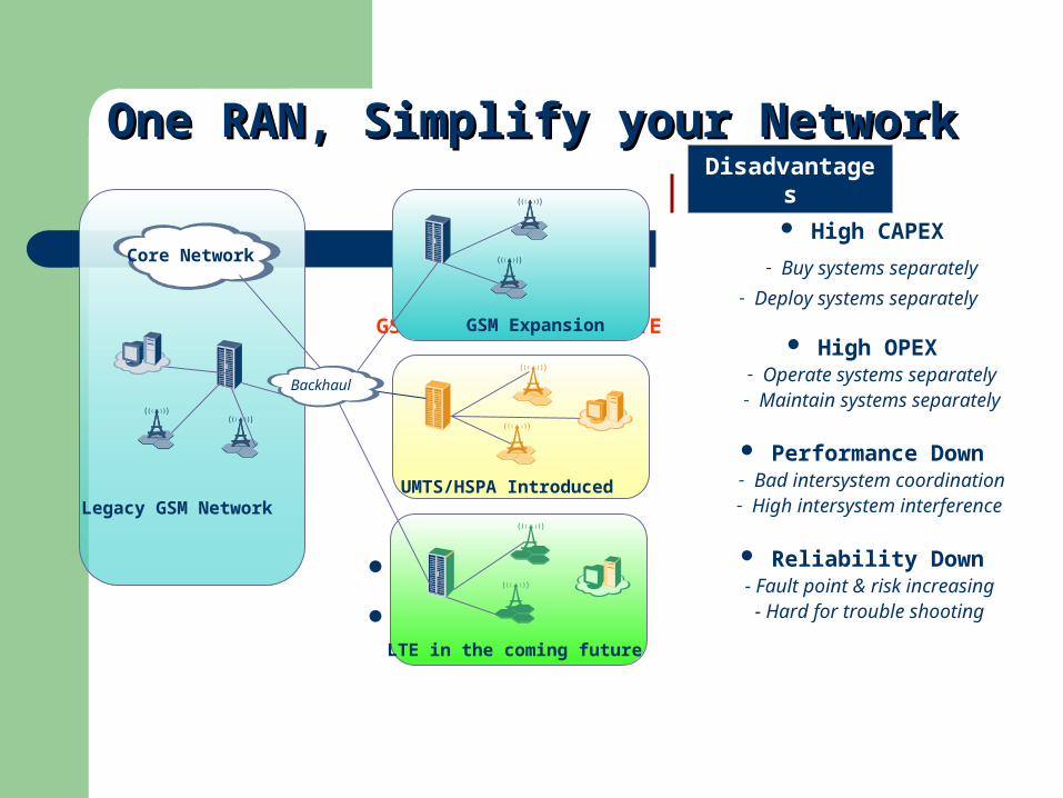
SingleRANGSM / UMTS / HSPA / LTEGSM Expansion
One RAN, Simplify your NetworkOne RAN, Simplify your Network
Legacy GSM NetworkUMTS/HSPA Introduced
Disadvantages High CAPEX
- Buy systems separately
- Deploy systems separately
High OPEX- Operate systems separately- Maintain systems separately
Performance Down- Bad intersystem coordination- High intersystem interference
Reliability Down - Fault point & risk increasing
- Hard for trouble shooting
Core Network
Backhaul
www.3gpp.orgwww.radio-electronics.comwww.lteuniversity.comwww.cert.nat.tn
REFERENCES
![Long Term Evolution and Enhanced Packet Core (LTE and EPC ...ewh.ieee.org/r1/njcoast/LTE-ePCTalkOct24-2008[1].pdf · Long Term Evolution and Enhanced Packet Core (LTE and EPC)](https://img.pdfslide.us/doc/110x75/5a9753c27f8b9a9c5b8d2fc4/long-term-evolution-and-enhanced-packet-core-lte-and-epc-ewhieeeorgr1njcoastlte-epctalkoct24-20081pdflong.jpg)