Embed Size (px)
Citation preview
© 2012 Agilent Technologies
LTE-Advanced Design and Test Challenges - Carrier Aggregation
Presented by: Martha Zemede, Agilent Technologies
© 2012 Agilent Technologies 2
© 2012 Agilent Technologies
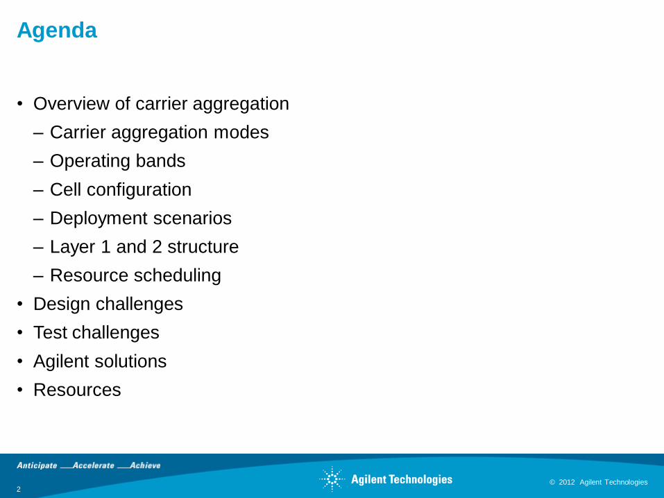
Agenda
• Overview of carrier aggregation
– Carrier aggregation modes
– Operating bands
– Cell configuration
– Deployment scenarios
– Layer 1 and 2 structure
– Resource scheduling
• Design challenges
• Test challenges
• Agilent solutions
• Resources
© 2012 Agilent Technologies 3
© 2012 Agilent Technologies
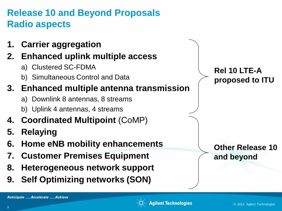
Release 10 and Beyond Proposals
Radio aspects
1. Carrier aggregation
2. Enhanced uplink multiple access
a) Clustered SC-FDMA
b) Simultaneous Control and Data
3. Enhanced multiple antenna transmission
a) Downlink 8 antennas, 8 streams
b) Uplink 4 antennas, 4 streams
4. Coordinated Multipoint (CoMP)
5. Relaying
6. Home eNB mobility enhancements
7. Customer Premises Equipment
8. Heterogeneous network support
9. Self Optimizing networks (SON)
Rel 10 LTE-A
proposed to ITU
Other Release 10
and beyond
© 2012 Agilent Technologies 4
© 2012 Agilent Technologies
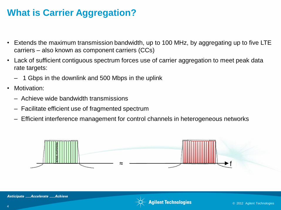
What is Carrier Aggregation?
• Extends the maximum transmission bandwidth, up to 100 MHz, by aggregating up to five LTE
carriers – also known as component carriers (CCs)
• Lack of sufficient contiguous spectrum forces use of carrier aggregation to meet peak data
rate targets:
– 1 Gbps in the downlink and 500 Mbps in the uplink
• Motivation:
– Achieve wide bandwidth transmissions
– Facilitate efficient use of fragmented spectrum
– Efficient interference management for control channels in heterogeneous networks
≈
Reso
urc
eb
lock
f
© 2012 Agilent Technologies 5
© 2012 Agilent Technologies
Band A Band B
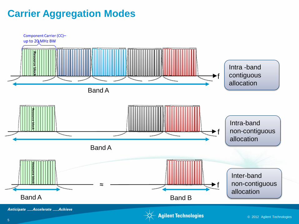
Carrier Aggregation Modes
Intra -band
contiguous
allocation
Reso
urc
eb
lock
f
≈
Reso
urc
eb
lock
f
Intra-band
non-contiguous
allocation
Inter-band
non-contiguous
allocation
Component Carrier (CC)–up to 20 MHz BW
Reso
urc
eb
lock
f
Band A
Band A
© 2012 Agilent Technologies 6
© 2012 Agilent Technologies
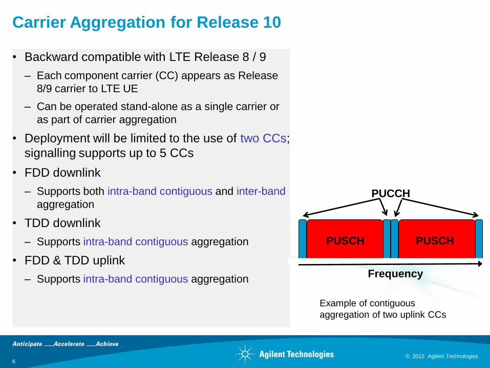
Carrier Aggregation for Release 10
• Backward compatible with LTE Release 8 / 9
– Each component carrier (CC) appears as Release
8/9 carrier to LTE UE
– Can be operated stand-alone as a single carrier or
as part of carrier aggregation
• Deployment will be limited to the use of two CCs;
signalling supports up to 5 CCs
• FDD downlink
– Supports both intra-band contiguous and inter-band
aggregation
• TDD downlink
– Supports intra-band contiguous aggregation
• FDD & TDD uplink
– Supports intra-band contiguous aggregation
PUSCH PUSCH
PUCCH
Frequency
Example of contiguous
aggregation of two uplink CCs

© 2012 Agilent Technologies 7
© 2012 Agilent Technologies
Carrier Aggregation –
Operating Bands for Release 10
• Intra-band contiguous CA:
– Bands 1 and 40 are supported:
• 15 and 20 MHz carrier bandwidths for Band 1
• 10, 15 and 20 MHz bandwidth in Band 40
Band E-UTRA
BandUplink (UL) operating band Downlink (DL) operating band Duplex
ModeBS receive / UE transmit BS transmit / UE receive
FUL_low – FUL_high FDL_low – FDL_high
CA_1 1 1920 MHz – 1980 MHz 2110 MHz – 2170 MHz FDD
CA_40 40 2300 MHz – 2400 MHz 2300 MHz – 2400 MHz TDD
Band E-UTRA
BandUplink (UL) operating band Downlink (DL) operating band Duplex
ModeBS receive / UE transmit BS transmit / UE receive
FUL_low – FUL_high FDL_low – FDL_high
CA_1-51 1920 MHz – 1980 MHz 2110 MHz – 2170 MHz
FDD5 824 MHz – 849 MHz 869 MHz – 894 MHz
• Inter-band non-contiguous CA:
– Bands 1 and 5 for 10 MHz CCs, one CC per band
© 2012 Agilent Technologies 8
© 2012 Agilent Technologies
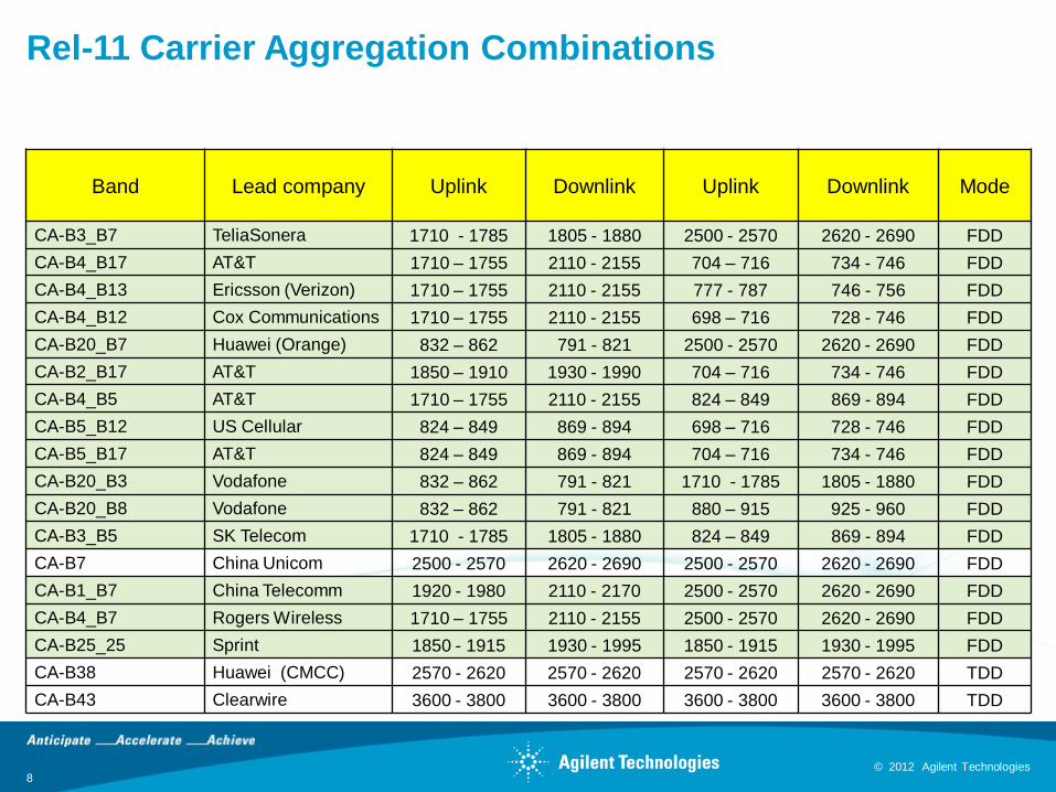
Rel-11 Carrier Aggregation Combinations
Band Lead company Uplink Downlink Uplink Downlink Mode
CA-B3_B7 TeliaSonera 1710 - 1785 1805 - 1880 2500 - 2570 2620 - 2690 FDD
CA-B4_B17 AT&T 1710 – 1755 2110 - 2155 704 – 716 734 - 746 FDD
CA-B4_B13 Ericsson (Verizon) 1710 – 1755 2110 - 2155 777 - 787 746 - 756 FDD
CA-B4_B12 Cox Communications 1710 – 1755 2110 - 2155 698 – 716 728 - 746 FDD
CA-B20_B7 Huawei (Orange) 832 – 862 791 - 821 2500 - 2570 2620 - 2690 FDD
CA-B2_B17 AT&T 1850 – 1910 1930 - 1990 704 – 716 734 - 746 FDD
CA-B4_B5 AT&T 1710 – 1755 2110 - 2155 824 – 849 869 - 894 FDD
CA-B5_B12 US Cellular 824 – 849 869 - 894 698 – 716 728 - 746 FDD
CA-B5_B17 AT&T 824 – 849 869 - 894 704 – 716 734 - 746 FDD
CA-B20_B3 Vodafone 832 – 862 791 - 821 1710 - 1785 1805 - 1880 FDD
CA-B20_B8 Vodafone 832 – 862 791 - 821 880 – 915 925 - 960 FDD
CA-B3_B5 SK Telecom 1710 - 1785 1805 - 1880 824 – 849 869 - 894 FDD
CA-B7 China Unicom 2500 - 2570 2620 - 2690 2500 - 2570 2620 - 2690 FDD
CA-B1_B7 China Telecomm 1920 - 1980 2110 - 2170 2500 - 2570 2620 - 2690 FDD
CA-B4_B7 Rogers Wireless 1710 – 1755 2110 - 2155 2500 - 2570 2620 - 2690 FDD
CA-B25_25 Sprint 1850 - 1915 1930 - 1995 1850 - 1915 1930 - 1995 FDD
CA-B38 Huawei (CMCC) 2570 - 2620 2570 - 2620 2570 - 2620 2570 - 2620 TDD
CA-B43 Clearwire 3600 - 3800 3600 - 3800 3600 - 3800 3600 - 3800 TDD
© 2012 Agilent Technologies 9
© 2012 Agilent Technologies
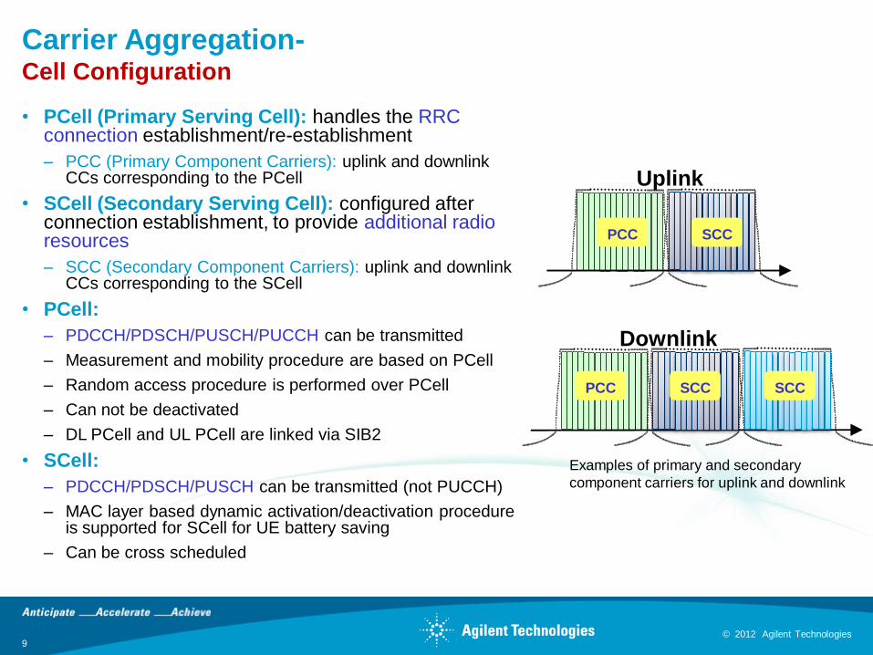
Carrier Aggregation-Cell Configuration
• PCell (Primary Serving Cell): handles the RRC connection establishment/re-establishment
– PCC (Primary Component Carriers): uplink and downlink CCs corresponding to the PCell
• SCell (Secondary Serving Cell): configured after connection establishment, to provide additional radio resources
– SCC (Secondary Component Carriers): uplink and downlink CCs corresponding to the SCell
• PCell:
– PDCCH/PDSCH/PUSCH/PUCCH can be transmitted
– Measurement and mobility procedure are based on PCell
– Random access procedure is performed over PCell
– Can not be deactivated
– DL PCell and UL PCell are linked via SIB2
• SCell:
– PDCCH/PDSCH/PUSCH can be transmitted (not PUCCH)
– MAC layer based dynamic activation/deactivation procedure is supported for SCell for UE battery saving
– Can be cross scheduled
SCC SCCPCC
Downlink
PCC SCC
Uplink
Examples of primary and secondary
component carriers for uplink and downlink
© 2012 Agilent Technologies 10
© 2012 Agilent Technologies
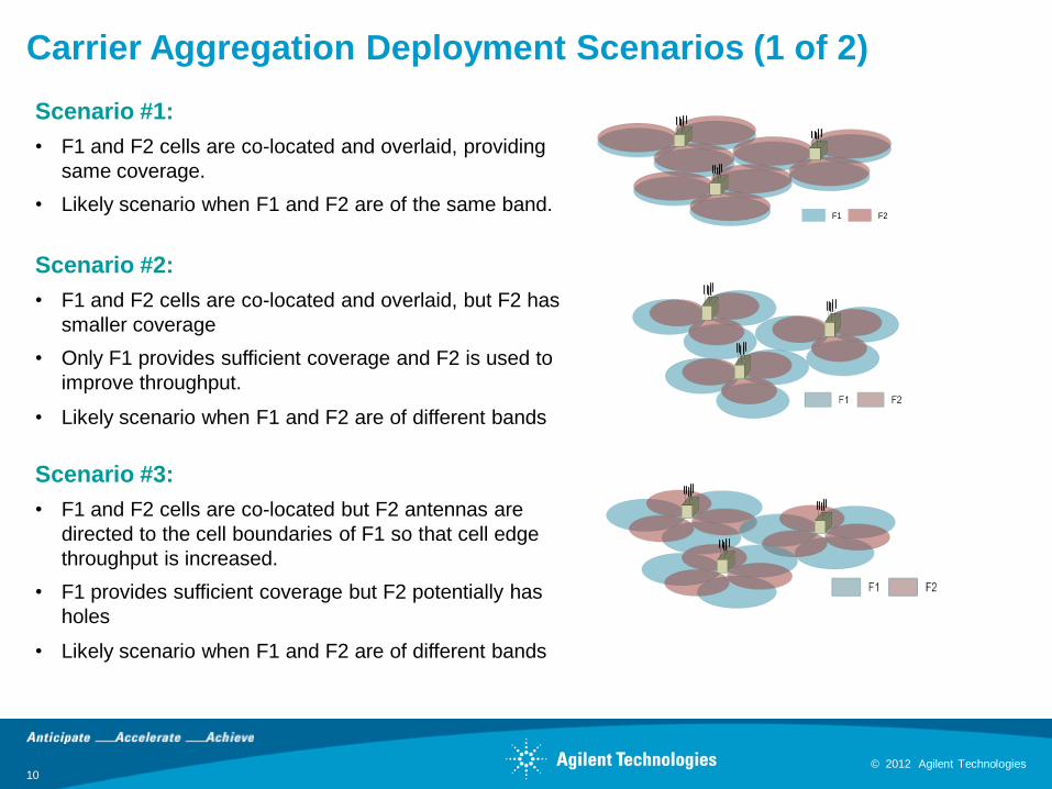
Carrier Aggregation Deployment Scenarios (1 of 2)
Scenario #2:
• F1 and F2 cells are co-located and overlaid, but F2 has
smaller coverage
• Only F1 provides sufficient coverage and F2 is used to
improve throughput.
• Likely scenario when F1 and F2 are of different bands
F1 F2
Scenario #3:
• F1 and F2 cells are co-located but F2 antennas are
directed to the cell boundaries of F1 so that cell edge
throughput is increased.
• F1 provides sufficient coverage but F2 potentially has
holes
• Likely scenario when F1 and F2 are of different bands
Scenario #1:
• F1 and F2 cells are co-located and overlaid, providing
same coverage.
• Likely scenario when F1 and F2 are of the same band.
© 2012 Agilent Technologies 11
© 2012 Agilent Technologies
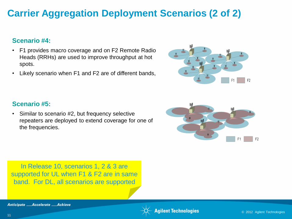
Carrier Aggregation Deployment Scenarios (2 of 2)
Scenario #4:
• F1 provides macro coverage and on F2 Remote Radio
Heads (RRHs) are used to improve throughput at hot
spots.
• Likely scenario when F1 and F2 are of different bands,
Scenario #5:
• Similar to scenario #2, but frequency selective
repeaters are deployed to extend coverage for one of
the frequencies.
In Release 10, scenarios 1, 2 & 3 are
supported for UL when F1 & F2 are in same
band. For DL, all scenarios are supported

© 2012 Agilent Technologies 12
© 2012 Agilent Technologies
Layer 2 Structure for Carrier Aggregation
• Data aggregation happens in MAC layer, the multi-carrier nature of carrier aggregation not visible to core network
• The MAC layer divides the data between different CCs and separate HARQ processes for each CC
Segm.
ARQ etc
Multiplexing UE1
Segm.
ARQ etc...
Scheduling / Priority Handling
Logical Channels
Transport Channels
MAC
RLCSegm.
ARQ etc
Segm.
ARQ etc
PDCP
ROHC ROHC ROHC ROHC
Radio Bearers
Security Security Security Security
...
HARQ HARQ...
Multiplexing UEn
HARQ HARQ...
CC1 CCx... CC1 CCy...
Multiplexing
...
Scheduling / Priority Handling
Transport Channels
MAC
RLC
PDCP
Segm.
ARQ etc
Segm.
ARQ etc
Logical Channels
ROHC ROHC
Radio Bearers
Security Security
HARQ HARQ...
CC1 CCx...
Layer 2 Structure for the UL (3GPP TR 36.912 V10.0.0, Figure 5.2.1-2)
Layer 2 Structure for the DL(3GPP TR 36.912 V10.0.0, Figure 5.2.1--1)
Independent
HARQ per CC
Independent
HARQ per CC
© 2012 Agilent Technologies
Channel coding
HARQ
modulation
Resource mapping
CC2
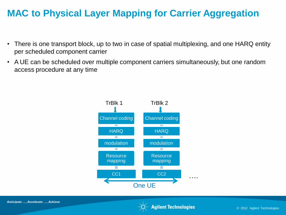
MAC to Physical Layer Mapping for Carrier Aggregation
• There is one transport block, up to two in case of spatial multiplexing, and one HARQ entity
per scheduled component carrier
• A UE can be scheduled over multiple component carriers simultaneously, but one random
access procedure at any time
Channel coding
HARQ
modulation
Resource mapping
CC1
One UE
TrBlk 1 TrBlk 2
….
© 2012 Agilent Technologies 14
© 2012 Agilent Technologies
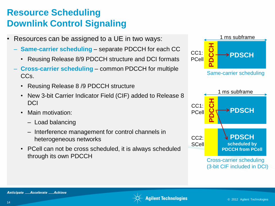
Resource Scheduling
Downlink Control Signaling
• Resources can be assigned to a UE in two ways:
– Same-carrier scheduling – separate PDCCH for each CC
• Reusing Release 8/9 PDCCH structure and DCI formats
– Cross-carrier scheduling – common PDCCH for multiple
CCs.
• Reusing Release 8 /9 PDCCH structure
• New 3-bit Carrier Indicator Field (CIF) added to Release 8
DCI
• Main motivation:
– Load balancing
– Interference management for control channels in
heterogeneous networks
• PCell can not be cross scheduled, it is always scheduled
through its own PDCCH
PD
CC
H
PDSCHCC1:
PCell
PD
CC
H
PDSCHCC1:
PCell
PDSCH scheduled by
PDCCH from PCell
CC2:
SCell
1 ms subframe
Cross-carrier scheduling
(3-bit CIF included in DCI)
1 ms subframe
Same-carrier scheduling
© 2012 Agilent Technologies 15
© 2012 Agilent Technologies
Macro Cell
Pico CellCC1
for Macro Cell
CC2
for Macro Cell
CC2
Low Power
CC1
Low Power
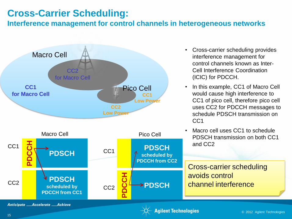
Cross-Carrier Scheduling:Interference management for control channels in heterogeneous networks
• Cross-carrier scheduling provides
interference management for
control channels known as Inter-
Cell Interference Coordination
(ICIC) for PDCCH.
• In this example, CC1 of Macro Cell
would cause high interference to
CC1 of pico cell, therefore pico cell
uses CC2 for PDCCH messages to
schedule PDSCH transmission on
CC1
• Macro cell uses CC1 to schedule
PDSCH transmission on both CC1
and CC2
PD
CC
H
PDSCH
PDSCH scheduled by
PDCCH from CC1
Macro Cell
PD
CC
H
PDSCH
PDSCH scheduled by
PDCCH from CC2
Pico Cell
CC1
CC2
CC1
CC2
Cross-carrier scheduling
avoids control
channel interference
© 2012 Agilent Technologies 16
© 2012 Agilent Technologies
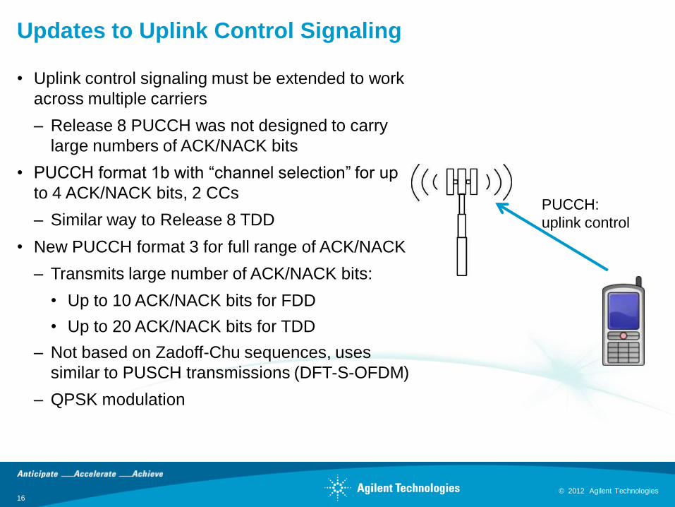
Updates to Uplink Control Signaling
• Uplink control signaling must be extended to work
across multiple carriers
– Release 8 PUCCH was not designed to carry
large numbers of ACK/NACK bits
• PUCCH format 1b with “channel selection” for up
to 4 ACK/NACK bits, 2 CCs
– Similar way to Release 8 TDD
• New PUCCH format 3 for full range of ACK/NACK
– Transmits large number of ACK/NACK bits:
• Up to 10 ACK/NACK bits for FDD
• Up to 20 ACK/NACK bits for TDD
– Not based on Zadoff-Chu sequences, uses
similar to PUSCH transmissions (DFT-S-OFDM)
– QPSK modulation
PUCCH:
uplink control
© 2012 Agilent Technologies 17
© 2012 Agilent Technologies
Agenda
• Overview of carrier aggregation
– Carrier aggregation modes
– Operating bands
– Cell configuration
– Deployment scenarios
– Layer 1 and 2 structure
– Resource scheduling
• Design challenges
• Test challenges
• Agilent solutions
• Resources

© 2012 Agilent Technologies 18
© 2012 Agilent Technologies
UE Transmitter Architecture for Various
Intra-Band Aggregation Scenarios
RF PA
RF filter
Multiplex
1 and 2 BB
D/AIFFT
L1
Single (baseband + IFFT + DAC + mixer + PA)
Aggregation Scenario: Intra-band contiguous
Multiplex
1 BB
Multiplex
2 BB
IFFT
IFFT
D/A
D/A
L1
RF PA
L2
RF filter
Multiple (baseband + IFFT + DAC), single (stage-1 IF mixer
+ combiner @ IF + stage-2 RF mixer + PA)
Aggregation Scenarios: Intra-band contiguous and non-
contiguous
Multiplex
1 BB
Multiplex
2 BB
IFFT
IFFT
D/A
D/A
RF PARF filter
L2
L1
Multiple (baseband + IFFT + DAC + mixer), low-
power combiner @ RF, and single PA
Aggregation Scenarios: Intra-band contiguous
and non-contiguous
Scenario A
Scenario B
Scenario C
Reference: 3GPP TR 36.912 v.10.0.0. Figure 11.3.2.1-1
© 2012 Agilent Technologies 19
© 2012 Agilent Technologies
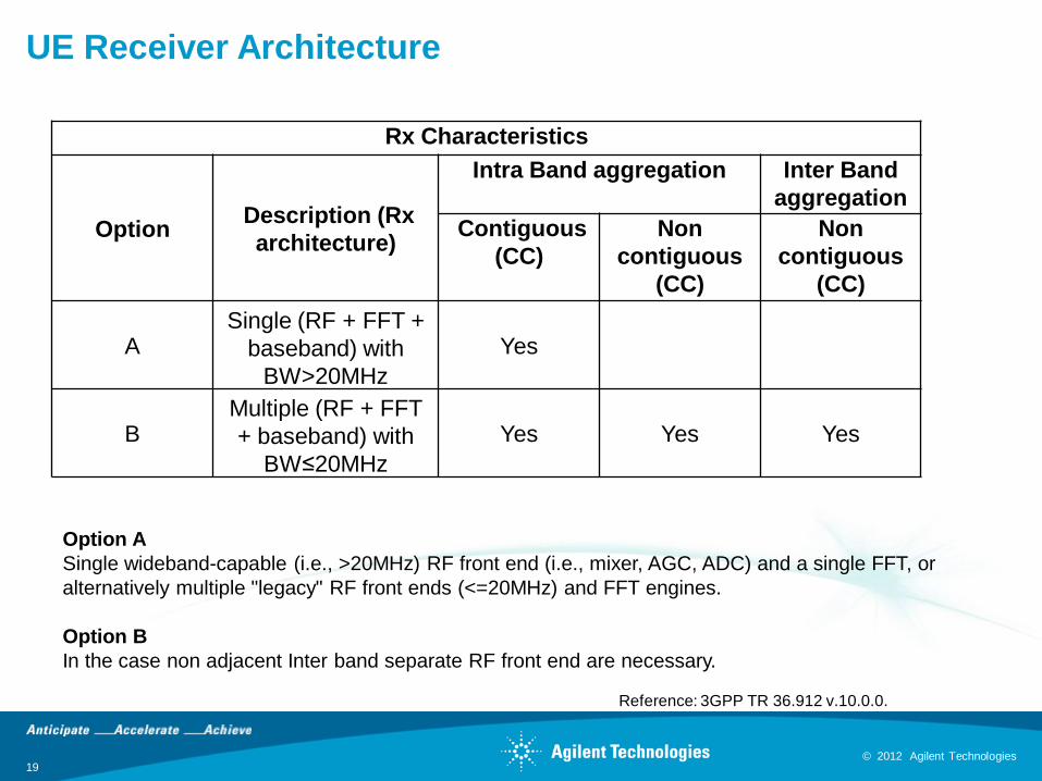
UE Receiver Architecture
Rx Characteristics
Option Description (Rx
architecture)
Intra Band aggregation Inter Band
aggregation
Contiguous
(CC)
Non
contiguous
(CC)
Non
contiguous
(CC)
ASingle (RF + FFT +
baseband) with
BW>20MHz
Yes
BMultiple (RF + FFT
+ baseband) with
BW≤20MHz
Yes Yes Yes
Option A
Single wideband-capable (i.e., >20MHz) RF front end (i.e., mixer, AGC, ADC) and a single FFT, or
alternatively multiple "legacy" RF front ends (<=20MHz) and FFT engines.
Option B
In the case non adjacent Inter band separate RF front end are necessary.
Reference: 3GPP TR 36.912 v.10.0.0.
© 2012 Agilent Technologies 20
© 2012 Agilent Technologies
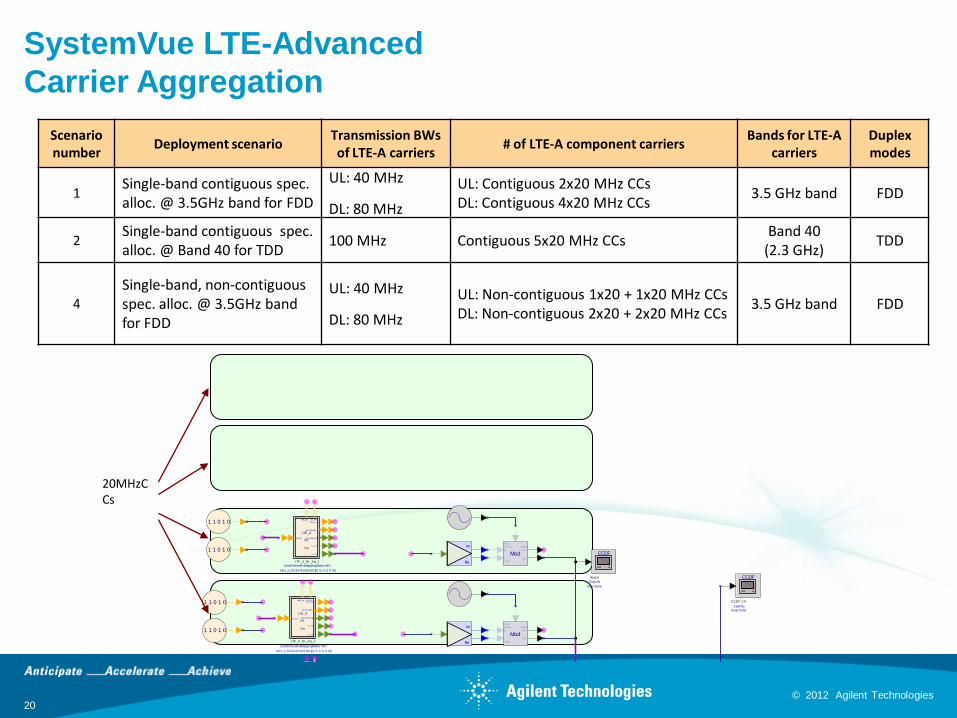
SystemVue LTE-Advanced
Carrier Aggregation
Scenario number
Deployment scenarioTransmission BWs of LTE-A carriers
# of LTE-A component carriersBands for LTE-A
carriersDuplex modes
1Single-band contiguous spec. alloc. @ 3.5GHz band for FDD
UL: 40 MHz
DL: 80 MHz
UL: Contiguous 2x20 MHz CCsDL: Contiguous 4x20 MHz CCs
3.5 GHz band FDD
2Single-band contiguous spec. alloc. @ Band 40 for TDD
100 MHz Contiguous 5x20 MHz CCsBand 40
(2.3 GHz)TDD
4
Single-band, non-contiguous spec. alloc. @ 3.5GHz band for FDD
UL: 40 MHz
DL: 80 MHz
UL: Non-contiguous 1x20 + 1x20 MHz CCsDL: Non-contiguous 2x20 + 2x20 MHz CCs
3.5 GHz band FDD
Re
Im
Env
1 1 0 1 0
1 1 0 1 0
UE1_Dat a
HARQ _Bit s
f r m _TD
f r m _FD
UE1_M odSym bols
UE1_ChannelBit s
SC_St at usUE1_PM I
LTE_A
DL
Src
UEs_n_SCID=0;0;0;0;0;0 [[0, 0, 0, 0, 0, 0]]
UserDefinedAntMappingMatrix=NO
LTE_A_DL_Src_2
FcChange
Spect rum Anal yzer
CCDF
Stop=10ms
Start=0s
CCDF_CA
CCDF
Stop=10ms
Start=0s
WoCA
ModOUT
QUAD
OUT
Freq
Phas e
Q
I
Am p
Re
Im1 1 0 1 0
1 1 0 1 0
UE1_Dat a
HARQ _Bit s
f r m _TD
f r m _FD
UE1_M odSym bols
UE1_ChannelBit s
SC_St at us
UE1_PM I
LTE_A
DL
Src
UEs_n_SCID=0;0;0;0;0;0 [[0, 0, 0, 0, 0, 0]]
UserDefinedAntMappingMatrix=NO
LTE_A_DL_Src_4
ModOUT
QUAD
OUT
Freq
Phas e
Q
I
Am p
Re
Im
1 1 0 1 0
1 1 0 1 0
UE1_Dat a
HARQ _Bit s
f r m _TD
f r m _FD
UE1_M odSym bols
UE1_ChannelBit s
SC_St at usUE1_PM I
LTE_A
DL
Src
UEs_n_SCID=0;0;0;0;0;0 [[0, 0, 0, 0, 0, 0]]
UserDefinedAntMappingMatrix=NO
LTE_A_DL_Src_3
ModOUT
QUAD
OUT
Freq
Phas e
Q
I
Am p
Re
Im
ModOUT
QUAD
OUT
Freq
Phas e
Q
I
Am p
1 1 0 1 0
1 1 0 1 0
UE1_Dat a
HARQ _Bit s
f r m _TD
f r m _FD
UE1_M odSym bols
UE1_ChannelBit s
SC_St at us
UE1_PM I
LTE_A
DL
Src
UEs_n_SCID=0;0;0;0;0;0 [[0, 0, 0, 0, 0, 0]]
UserDefinedAntMappingMatrix=NO
LTE_A_DL_Src_1
20MHzCCs
© 2012 Agilent Technologies 21
© 2012 Agilent Technologies
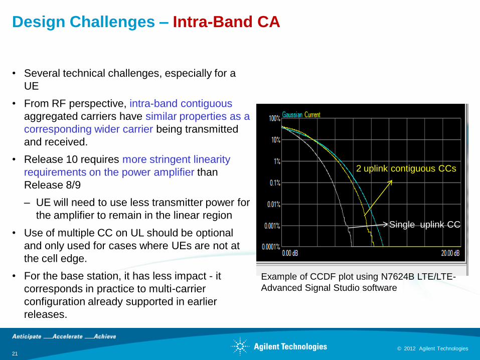
Design Challenges – Intra-Band CA
• Several technical challenges, especially for a
UE
• From RF perspective, intra-band contiguous
aggregated carriers have similar properties as a
corresponding wider carrier being transmitted
and received.
• Release 10 requires more stringent linearity
requirements on the power amplifier than
Release 8/9
– UE will need to use less transmitter power for
the amplifier to remain in the linear region
• Use of multiple CC on UL should be optional
and only used for cases where UEs are not at
the cell edge.
• For the base station, it has less impact - it
corresponds in practice to multi-carrier
configuration already supported in earlier
releases.
Example of CCDF plot using N7624B LTE/LTE-
Advanced Signal Studio software
2 uplink contiguous CCs
Single uplink CC
© 2012 Agilent Technologies 22
© 2012 Agilent Technologies
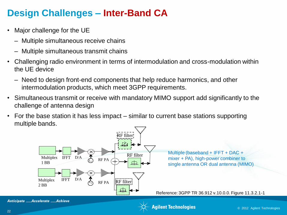
Design Challenges – Inter-Band CA
• Major challenge for the UE
– Multiple simultaneous receive chains
– Multiple simultaneous transmit chains
• Challenging radio environment in terms of intermodulation and cross-modulation within
the UE device
– Need to design front-end components that help reduce harmonics, and other
intermodulation products, which meet 3GPP requirements.
• Simultaneous transmit or receive with mandatory MIMO support add significantly to the
challenge of antenna design
• For the base station it has less impact – similar to current base stations supporting
multiple bands.
Multiplex
1 BB
Multiplex
2 BB
IFFT
IFFT
D/A
D/ARF PA RF filterL2
L1RF PA
RF filter
RF filter
Multiple (baseband + IFFT + DAC +
mixer + PA), high-power combiner to
single antenna OR dual antenna (MIMO)
Reference: 3GPP TR 36.912 v.10.0.0. Figure 11.3.2.1-1
© 2012 Agilent Technologies 23
© 2012 Agilent Technologies
Agenda
• Overview of carrier aggregation
– Carrier aggregation modes
– Operating bands
– Cell configuration
– Deployment scenarios
– Layer 1 and 2 structure
– Resource scheduling
• Design challenges
• Test challenges
• Agilent solutions
• Resources
© 2012 Agilent Technologies 24
© 2012 Agilent Technologies
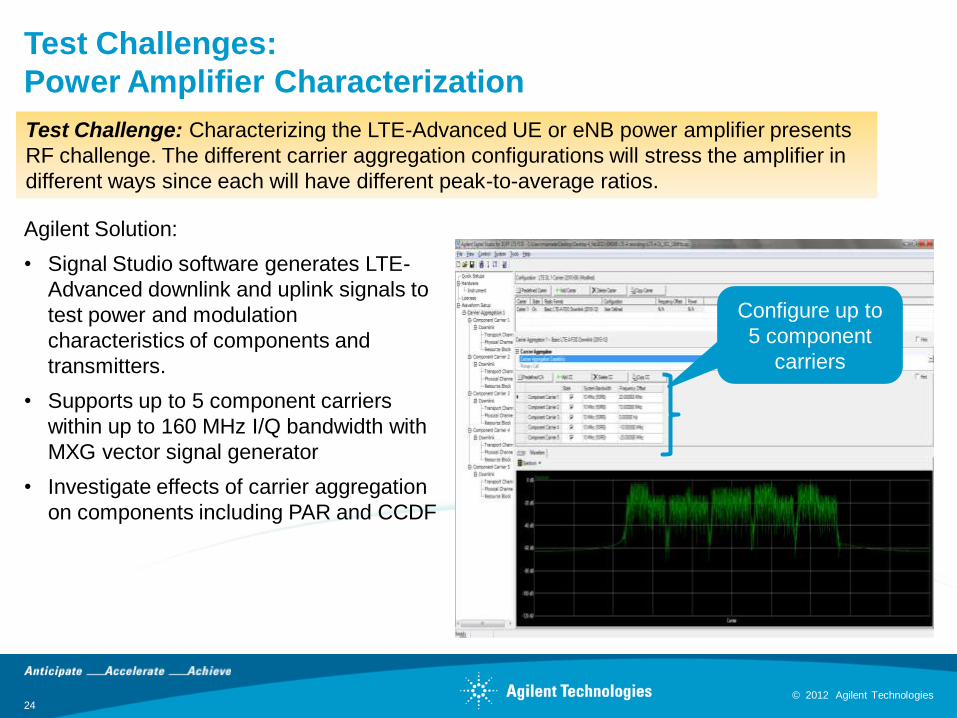
Test Challenges:
Power Amplifier Characterization
Agilent Solution:
• Signal Studio software generates LTE-
Advanced downlink and uplink signals to
test power and modulation
characteristics of components and
transmitters.
• Supports up to 5 component carriers
within up to 160 MHz I/Q bandwidth with
MXG vector signal generator
• Investigate effects of carrier aggregation
on components including PAR and CCDF
Test Challenge: Characterizing the LTE-Advanced UE or eNB power amplifier presents
RF challenge. The different carrier aggregation configurations will stress the amplifier in
different ways since each will have different peak-to-average ratios.
Configure up to
5 component
carriers
© 2012 Agilent Technologies 25
© 2012 Agilent Technologies
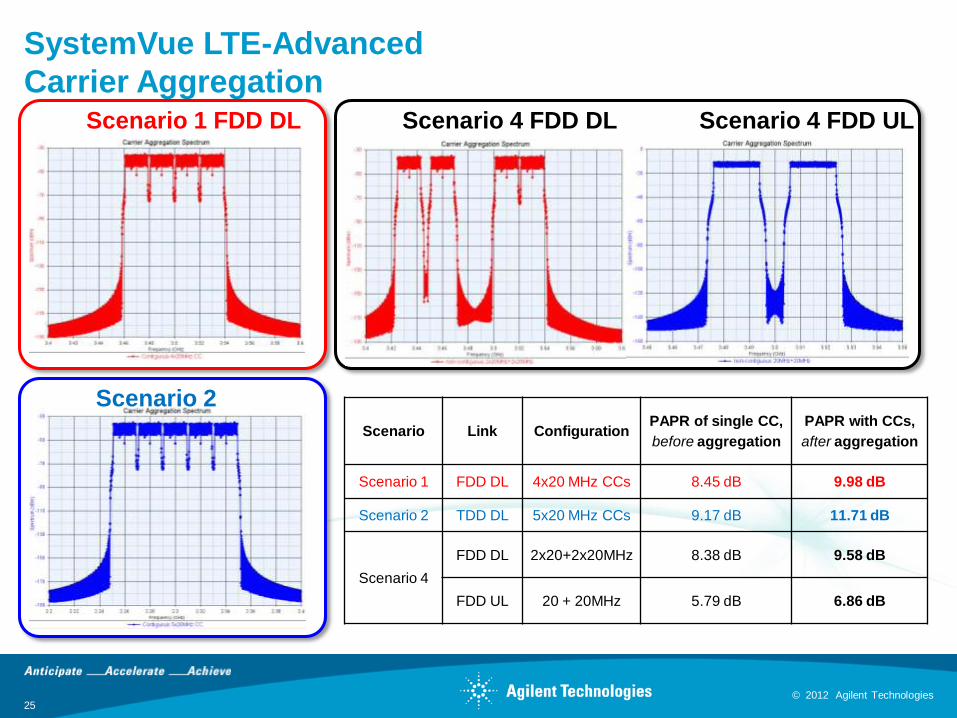
SystemVue LTE-Advanced
Carrier Aggregation
Scenario Link ConfigurationPAPR of single CC,
before aggregation
PAPR with CCs,
after aggregation
Scenario 1 FDD DL 4x20 MHz CCs 8.45 dB 9.98 dB
Scenario 2 TDD DL 5x20 MHz CCs 9.17 dB 11.71 dB
Scenario 4
FDD DL 2x20+2x20MHz 8.38 dB 9.58 dB
FDD UL 20 + 20MHz 5.79 dB 6.86 dB
Scenario 1 FDD DL
Scenario 2
TDD DL
Scenario 4 FDD DL Scenario 4 FDD UL
© 2012 Agilent Technologies 26
© 2012 Agilent Technologies
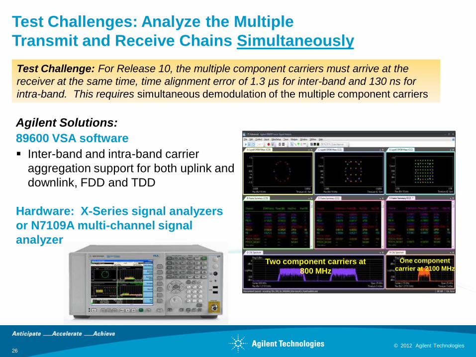
Test Challenges: Analyze the Multiple
Transmit and Receive Chains Simultaneously
Agilent Solutions:
89600 VSA software
Inter-band and intra-band carrier
aggregation support for both uplink and
downlink, FDD and TDD
Hardware: X-Series signal analyzers
or N7109A multi-channel signal
analyzer
Two component carriers at
800 MHz
One component
carrier at 2100 MHz
Test Challenge: For Release 10, the multiple component carriers must arrive at the
receiver at the same time, time alignment error of 1.3 µs for inter-band and 130 ns for
intra-band. This requires simultaneous demodulation of the multiple component carriers
© 2012 Agilent Technologies 27
© 2012 Agilent Technologies
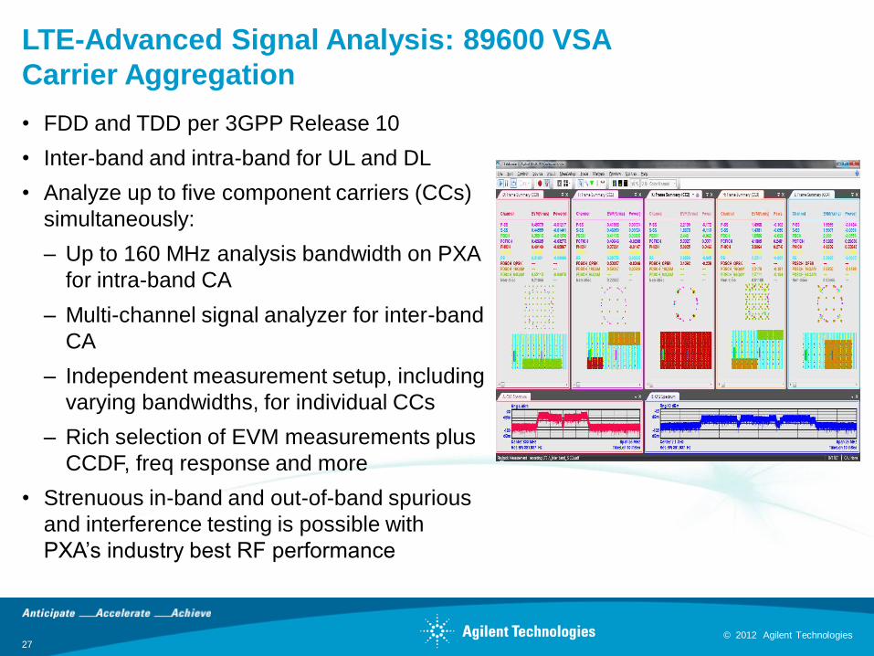
LTE-Advanced Signal Analysis: 89600 VSA
Carrier Aggregation
• FDD and TDD per 3GPP Release 10
• Inter-band and intra-band for UL and DL
• Analyze up to five component carriers (CCs)
simultaneously:
– Up to 160 MHz analysis bandwidth on PXA
for intra-band CA
– Multi-channel signal analyzer for inter-band
CA
– Independent measurement setup, including
varying bandwidths, for individual CCs
– Rich selection of EVM measurements plus
CCDF, freq response and more
• Strenuous in-band and out-of-band spurious
and interference testing is possible with
PXA’s industry best RF performance
© 2012 Agilent Technologies 28
© 2012 Agilent Technologies
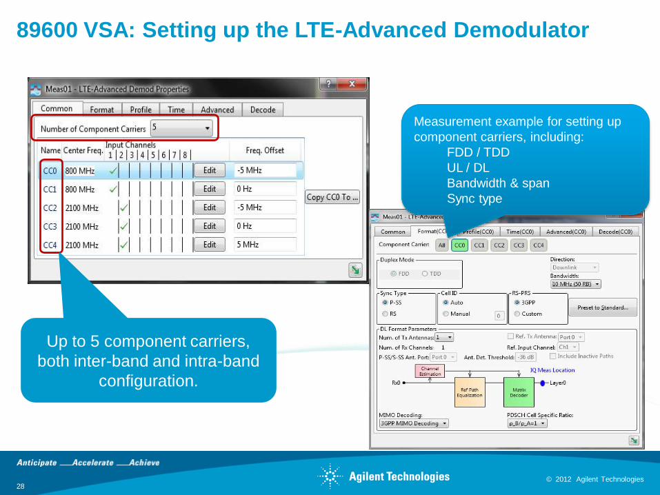
89600 VSA: Setting up the LTE-Advanced Demodulator
Measurement example for setting up
component carriers, including:
FDD / TDD
UL / DL
Bandwidth & span
Sync type
Up to 5 component carriers,
both inter-band and intra-band
configuration.
© 2012 Agilent Technologies 29
© 2012 Agilent Technologies
≈
Reso
urc
eb
lock
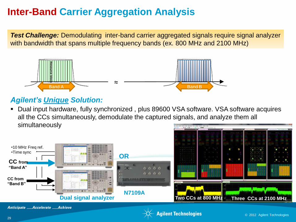
Inter-Band Carrier Aggregation Analysis
Band A Band B
N7109A
OR
Test Challenge: Demodulating inter-band carrier aggregated signals require signal analyzer
with bandwidth that spans multiple frequency bands (ex. 800 MHz and 2100 MHz)
•10 MHz Freq ref.
•Time sync
CC from
“Band A”
CC from
“Band B”
Dual signal analyzer
Agilent’s Unique Solution:
Dual input hardware, fully synchronized , plus 89600 VSA software. VSA software acquires
all the CCs simultaneously, demodulate the captured signals, and analyze them all
simultaneously
Two CCs at 800 MHz Three CCs at 2100 MHz
© 2012 Agilent Technologies 30
© 2012 Agilent Technologies
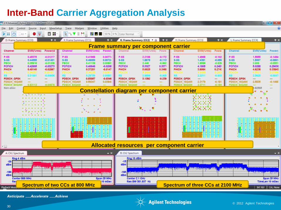
Inter-Band Carrier Aggregation Analysis
Allocated resources per component carrier
Constellation diagram per component carrier
Spectrum of two CCs at 800 MHz
Frame summary per component carrier
Spectrum of three CCs at 2100 MHz
© 2012 Agilent Technologies 31
© 2012 Agilent Technologies
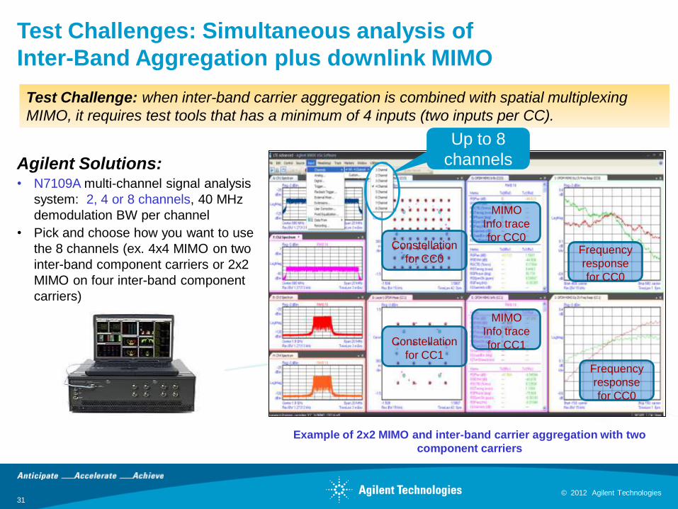
Test Challenges: Simultaneous analysis of
Inter-Band Aggregation plus downlink MIMO
Agilent Solutions:• N7109A multi-channel signal analysis
system: 2, 4 or 8 channels, 40 MHz
demodulation BW per channel
• Pick and choose how you want to use
the 8 channels (ex. 4x4 MIMO on two
inter-band component carriers or 2x2
MIMO on four inter-band component
carriers)
Test Challenge: when inter-band carrier aggregation is combined with spatial multiplexing
MIMO, it requires test tools that has a minimum of 4 inputs (two inputs per CC).
Up to 8
channels
MIMO
Info trace
for CC0
MIMO
Info trace
for CC1
Frequency
response
for CC0
Frequency
response
for CC0
Constellation
for CC0
Constellation
for CC1
Example of 2x2 MIMO and inter-band carrier aggregation with two
component carriers
© 2012 Agilent Technologies 32
© 2012 Agilent Technologies
Agenda
• Overview of carrier aggregation
– Carrier aggregation modes
– Operating bands
– Cell configuration
– Deployment scenarios
– Layer 1 and 2 structure
– Resource scheduling
• Design challenges
• Test challenges
• Agilent solutions
• Resources
© 2012 Agilent Technologies 33
© 2012 Agilent Technologies
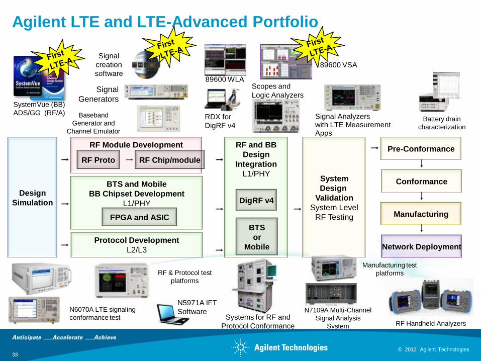
Agilent LTE and LTE-Advanced Portfolio
Signal
Generators
RDX for
DigRF v4
Systems for RF and
Protocol Conformance
RF Module Development
RF Proto RF Chip/module
Design
Simulation
BTS and Mobile
BB Chipset Development
L1/PHY
FPGA and ASIC
Conformance
RF and BB
Design
Integration
L1/PHYSystem
Design
Validation
System Level
RF Testing
BTS
or
MobileProtocol Development
L2/L3
DigRF v4
Pre-Conformance
Network Deployment
Manufacturing
89600 VSA
SystemVue (BB)
ADS/GG (RF/A)
N5971A IFT
Software
Scopes and
Logic Analyzers
Baseband
Generator and
Channel Emulator
Signal
creation
software
RF Handheld Analyzers
Manufacturing test
platforms
Battery drain
characterization
N6070A LTE signaling
conformance test
RF & Protocol test
platforms
Signal Analyzerswith LTE Measurement Apps
89600 WLA
N7109A Multi-Channel
Signal Analysis
System
© 2012 Agilent Technologies
Summary
• Carrier aggregation is one of the most important features for LTE-
Advanced enabling:
– Higher data rates
– Facilitate efficient use of fragmented spectrum
– Interference management in heterogeneous networks
• It is introduced in LTE Release 10 with deployment of two component
carriers and will be extended with Rel. 11and beyond
• It introduces various design challenges, especially for UE
• Test challenges for multi-carrier EVM requiring simultaneous demodulation
of both inter-band and intra-band signal configurations
• Agilent was first to market with LTE-Advanced solution addressing system
simulation, signal generation and analysis tools
34
© 2012 Agilent Technologies 35
© 2012 Agilent Technologies
For More Information
Agilent Resources
• LTE-Advanced application and product info: www.agilent.com/find/lteadvanced
• 89600 VSA product information: www.agilent.com/find/vsa
• X-Series signal analyzer product information: www.agilent.com/find/xseries
• N7109A multi-channel signal analyzer information: www.agilent.com/find/N7109A
• Signal Studio product information: www.agilent.com/find/signalstudio
Key LTE-Advanced Documents
• Historical documents:
– Study Item RP-080599: ftp://ftp.3gpp.org/tsg_ran/TSG_RAN/TSGR_41/Docs/RP-080599.zip
– Requirements TR 36.913 v9.0.0 (2009-12): ftp://ftp.3gpp.org/Specs/html-info/36913.htm
– Study Phase Technical Report TR 36.912 v9.3.0 (2010-06): ftp://ftp.3gpp.org/Specs/html-
info/36912.htm
• The LTE-A specifications are now drafted in the Release 10 specifications
ftp.3gpp.org/specs/latest/Rel-10/
© 2012 Agilent Technologies
THANK YOU!