Embed Size (px)
Citation preview

Image SensorsL t I
p. 1
Lecture IW ill l k l i ( i We will look at several active range cameras (stereo is a passive technique).
One active range camera is studied in more detail during the O e ac e a ge ca e a s s ud ed o e de a du g elaboratory assignment.
Some applications from SICK-IVP, Mjärdevi LinköpingMICROSOFT KINECT 1 d 2 ( lid f P E ik F é ) MICROSOFT KINECT 1 and 2 (slides from Per-Erik Forssén)
Literature Short about some active range cameras: Maria Magnusson Short about some active range cameras: Maria Magnusson
(Figure) Active Range Imaging 2: From a PhD-thesis by Mattias
Johannesson (Fig Table)Johannesson (Fig., Table) Mesa Data sheet on SR3000 (Not for sale any more, but an
example of a range camera principle, found in e.g. Kinect2.)
Maria Magnusson, CVL, Dept. of Electrical Engineering, Linköping University
Wh t i i ?
p. 2
What is a range image?
Normal intensity image Range image
Fig. 1.1Compare with depth coding in 3D visualization
Differenti i l
p. 3
range camera principles I) Time-of-flight
a) Light pulse and time measurement b) Amplitude modulated light and phase shift b) Amplitude modulated light and phase shift
measurement II) Active light and triangulation) g g
a) “Single spot” with triangulation b) “Sheet-of-light” with triangulation c) “Structured light” with triangulation d) “Gray-coded patterns” with triangulation
i) Stationary scene or moving scene i) Stationary scene or moving scene ii) Scanning or stationary light
Ia) Time-of-flight. p. 4
Light pulse and time measurement Same idea as RADAR: send out a light pulse and
and measure the time it takes for it to come back: s=v•t distance=s/2s=v•t, distance=s/2.
Sometimes called LIDAR or LADAR, (light+RADAR) Demands an accurate clock since v=3•108 m/s Demands an accurate clock, since v=3•108 m/s
Clock accuracy Depth accuracy
1 ms 300km
1 ns 3dm1 ns 3dm
1 ps 0.3mm

Ib) Time-of-flight. Amplitude modu-p. 5
lated light and phase shift measurement
objectHere with
scanning lightReflectedlight
Amplitude =>
light
Laser light,amplitude Scanning
pintensity
Receivera p tude
modulated with a
Scanning mirror
Phase =>sine wave distance
Reference signal
Ib) Time-of-flight. Amplitude modu-p. 6
lated light and phase shift measurementTh h diff b h f i l d h The phase difference between the reference signal and the re-ceived signal gives the time difference, which gives the range.
There is an ambiguity in phase/time difference. In the figure, e e s a a b gu y p ase/ e d e e ce e gu e,time difference can be 0.1 or 0.6.
In theory: Two amplitude modulated signals with frequencies with no common factor can measure all ranges.
Ib) Time-of-flight. Amplitude modu-p. 7
lated light and phase shift measurementTh MESA SR 3000 SR 4000 SR 4500 The MESA camera SR-3000, SR-4000, SR-4500
No scanning. Sends out amplitude modulated IR-light in many directions at the same time
See the datasheet on SR-3000 Catches a 3D scene in real time 176 X 144 sensor elements 176 X 144 sensor elements Non-ambiguous range: 7.5m Distance resolution: ≈1% of range Not for sale any more, but the principle is
similar to Kinect 2, see last slides.
II) A ti li ht d t i l ti
p. 8
II) Active light and triangulation The position of the laser point on the camera
sensor (s,t) gives an (x,y,r)-point on the object.
1.6
Fig.

IIa) ”Single spot”ith t i l ti
p. 9
with triangulation
Fig. 1.3
IIb) ”Sheet-of-light” ith t i l ti
p. 10
with triangulation
Fig. 1.4
IIc) “Structured light” with t i l ti
p. 11
triangulationH id Here a grid pattern – a kind of precursor to KINECT 1.
Disadvantage: The pattern of the objects cannot be too much wrinkled because too much wrinkled because then corresponding points cannot be determined.
Figure 1.2potatoes
IId) ”Gray coded patterns” ith t i l ti
p. 12
with triangulation
Fig. 1.5

The Lens law p. 13
(You should already know it.)object l
The lens law:
object lens
i lA
fba111
image planeA
Bfba
where f is the focal lengthg
The lens law states that if the image plane is located at the distance b from the lens, then the object at , jdistance a from the lens will give a sharp image.
S h i fl ’ diti
p. 14
Scheimpflug’s conditionIf Scheimpflug’s
tantan
If Scheimpflug scondition is fulfilled,
the whole sensor is in
Wh t h
00 bathe whole sensor is in
the focal plane!Laser Sensor plane What hap-
pens if thecondition
sheet Optical axis
Sensor plane
conditiononly is
approxima-
axis0ba
pptively
fulfilled?b
a
tana
Fig. 2.3b 0a
Example of suitable values forf b d β
p. 15
f, b0, α and β
f [mm] b0 [mm] [o] [o]
18 18 4 45 1 4318
75
18.4
76.8
45
45
1.43
1.36
18
75
18.4
76 8
63
63
2.81
2 6775
18
76.8
18.4
63
85
2.67
15.98
bl75 76.8 85 15.21
On the following slides: 5 sheet-of-lightTable 3
On the following slides: 5 sheet-of-light arrangements with different geometry
IIb) Arrangement 1Ad t S h i fl ’
p. 16
Advantages: Scheimpflug’scondition is fulfilled sincetan= tan= 0tan tan 0The range-value = const • sensor coordinate
Disadvantage: Does notwork for very rough objectswork for very rough objects.
Fig. 2.4

IIb) Arrangement 2 = A 1 t t d 45 o
p. 17
Arr. 1 rotated 45 o
Advantage & Disadvantage:Advantage & Disadvantage: as for arrangement 1
Fig. 2.5
Can be used to measure the roughness on a metal sheet.
IIb) Arrangement 3 p. 18
Advantage: Scheimpflug’scondition is fulfilled sincefulfilled sincetan= tan= 0
Disadvantages:- The sensor hasto be moved in the camera.Uneven illumination
Fig. 2.6- Uneven illuminationdue to the cos4 law.
IIb) A t 4 SICK IVP!
p. 19
IIb) Arrangement 4 SICK-IVP!
Disadvantages:- The sensor mayyneed to be tiltedin the camera.
- The range-value≠ Const • sensorcoordinatecoordinate.
Fig. 2.7
IIb) A t 5
p. 20
IIb) Arrangement 5Advantages: The range-value g= const • sensor
di tcoordinate
Disadvantages:g- The sensorneed to beil d i htilted in thecamera.
- Scheimpflug’s- Scheimpflug scondition isnot fulfilled.
Fig. 2.8

p. 21
Determination of the coordinate xTh iti i d t i d b th iti f The x position is determined by the position of the laser sheet
y xy
rr
Fig. 2.7
Determination of the range coordinate rp. 22
g
cos
cossin0 sbB
Eq. 2.15
sinsincoscos
00 sbbr
sincoscos
s
s L0b
B
L
xy
B
OC
s hibx
y
rOC
1b 2bsin0b
Fig. 2.90R 1m 2m
1b 2br
Determination ofp. 23
the width coordinate yBt
Eq. 2.21
tancos1sincos ssb
Bty
sin1sincos
00 sb
sb
Sensor plane
ba
p
t
OCxrOCx
y t
Fig. 2.10y
Range and width for =0 (when the p. 24
sensor is not tilted in the camera)
E 2 17tan sb Eq. 2.17
tan
tan
0
0
sbsbBr
Eq 2 22Bty Eq. 2.22
sincos0 sby

Range and width for ==0 p. 25
(Arrangement 1 and 2)
E 2 16Bs Eq. 2.16range!linear 0b
Bsr
th!linear widBty th!linear wid
0by
C lib ti diff t th d
p. 26
Calibration, different methodsThe nkno n parameters
(Just measuring )
The unknown parameters,, , bo, s(0), t(0) have to be determined in some way.
(Just measuring.) Present known points (yi,ri) to the system and solve the
parameters from Eq. (2.15) and (2.21). There exists only iterative methodsiterative methods.
Present known points (yi,ri) to the system and receive a polynomial approximation of Eq. (2.15) and (2.21).
Present known points (yi,ri) to the system and receive Present known points (yi,ri) to the system and receive (si,ti). This gives a 2D table for (s,t).
The projection of the laser plane to the image sensor is a homography. The complicated equations for the range coordinate r(s,t) and the width coordinate y(s,t) can be ( , ) y( , )replaced by calibrating a homography (lab task).
Calibration of Laser Triangulating Came-p. 27
ras in Small Fields of View (optional) An advanced very careful calibration method was
developed in a Master Thesis work at SICK-IVP 20132013.
The movement of the object was involved in the calibration process a consequently a full 3D calibration process, a consequently a full 3D calibration was received.
Search Daniel Rydström in DIVA! Search Daniel Rydström in DIVA! Calibration object:
Calibration of Laser Triangulating Came-p. 28
ras in Small Fields of View (optional)
~
10~ ZtRHPDU T
U=(u,v)T are the pixel coordinates on the sensor.
10
D is the distortion function of the lens H is the homography from laser plane to real
image plane P is the skew transformation onto the laser plane R and t determine the positions and orientation of
the calibration object relative the laser plane~
are homogeneous 3D points that are defined in the calibration object coordinate systemZ

A pseudo range image and its corre-p. 29
sponding pseudo intensity image
t f txs , txfs ,
From pseudo-coordinates (s,t) t l di t ( )
p. 30
to real coordinates (r,y)tt
s Use the equationsequations
given aboveor theor the
homographyreceived
f omfromcalibration.
rObs! Denser sampling
yObs! Denser samplingpoints on top after con-
version to real coordinates
A t f t
p. 31
Artefacts Varying object reflectivity Occlusion
Laser occlusion Sensor occlusion
V i bj t fl ti it
p. 32
Varying object reflectivityL i tLaser input
intensityObjectreflec-tivity
Correctpeak Sensor positionpeak
R fl t dOb-
p
Reflected intensity
Observedpeak
Sensor positionFig. 2.12Fig. 2.13

L & l iLaser
p. 33
Laser & sensor occlusion
esu
rfac
eSensor id
den
sSensor
= h
Fig. 2.15
Detection ofth l li th
p. 34
the laser line on the sensor
Fig. 1.6
Detection ofth l li th
p. 35
the laser line on the sensor Max: pos (a+b)/2 Max: pos = (a+b)/2 Thresh: pos = (n+m)/2 Cog: pos = [Σ x I(x)] / [Σ I(x)] Cog: pos [Σ x I(x)] / [Σ I(x)] Derivate and search for the zero-crossing Sub-pixel correlation with a Gaussian function
Intensity,I(x)
Max
Threshold
n a b m Fig. 4.1
Gray coded patternsi t d f ” h t f li ht”?
p. 36
instead of ”sheet-of light”? Advantage:logN patternslogN patternsinstead of Nsheet-of-light
The logNbinary images
b positions!can becombined toone imageone image with coded positions in every pixel. ConsequentlyN diff tN different codes are possible
Figure 1.3possible.
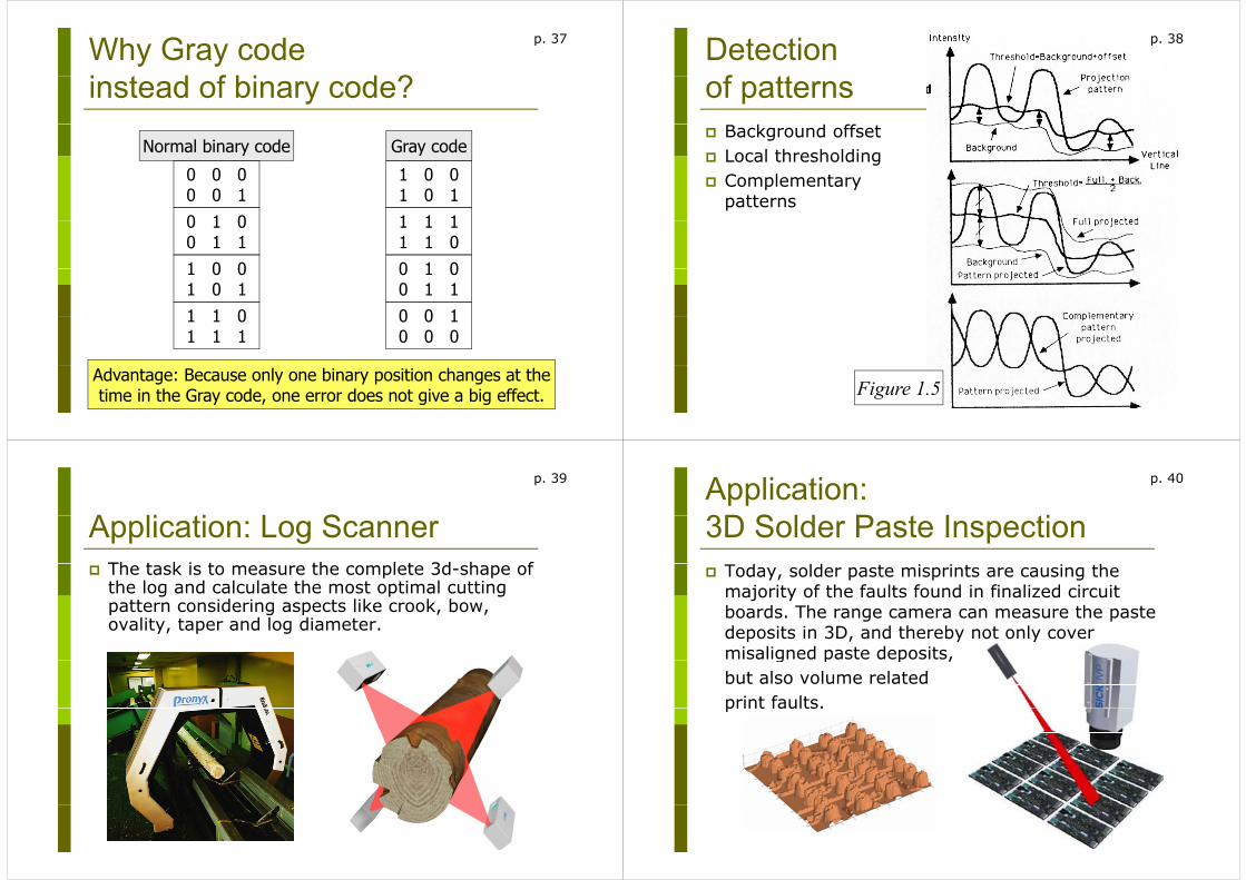
Why Gray code i t d f bi d ?
p. 37
instead of binary code?
Normal binary code
0 0 0
Gray code
1 0 00 0 00 0 10 1 0
1 0 01 0 11 1 10 1 0
0 1 11 0 0
1 1 11 1 00 1 01 0 0
1 0 11 1 0
0 1 00 1 10 0 11 1 0
1 1 10 0 10 0 0
Advantage: Because only one binary position changes at thetime in the Gray code, one error does not give a big effect.
Detection f tt
p. 38
of patterns Background offset Local thresholding Complementary
patterns
Figure 1.5
A li ti L S
p. 39
Application: Log ScannerTh t k i t th l t 3d h f The task is to measure the complete 3d-shape of the log and calculate the most optimal cutting pattern considering aspects like crook, bow, patte co s de g aspects e c oo , bo ,ovality, taper and log diameter.
Application:3D S ld P t I ti
p. 40
3D Solder Paste Inspection Today, solder paste misprints are causing the
majority of the faults found in finalized circuit boards The range camera can measure the paste boards. The range camera can measure the paste deposits in 3D, and thereby not only cover misaligned paste deposits,g p p ,but also volume relatedprint faults.print faults.

Application:Bli t P k I ti
p. 41
Blister Pack Inspection Inspection Task:
Each blister in every package should be checked for shape and integrityshape and integrity.
Also it should be verified that the blister contains a pill.
Application: Verification of C t t i P li B
p. 42
Content in Praline Boxes Inspection Task:
1. The shape of the pralines: are they shaped correctly? 2 The right position of the pralines in the box: is the 2. The right position of the pralines in the box: is the
right praline in the correct position? 3. The height of the pralines: have more pralines than
required been added?
Mi ft Ki t 1
p. 43
Microsoft Kinect 1 Based on structured light with random dots and
triangulationU i t f t Xb 360 User interface to Xbox 360
Arrived in Sweden N b 10 2010November 10, 2010
Microsoft Kinect:RGB D
p. 44
RGB-D sensor A - NIR-laser projector B - CMOS colour camera C - CMOS NIR camera

Microsoft Kinect:D th f t i l ti
p. 45
Depth from triangulationA B CA B C
Microsoft Kinect:D th f t i l ti
p. 46
Depth from triangulationA B CA B C
Microsoft Kinect and others. P t t
p. 47
Patent. Based on structured light
with random dot pattern according to a patent according to a patent from the Israeli company Primesense.
Many variants: Microsoft Kinect, Asus Xtion, Primesense, Carmine…
Structured light withd d t tt
p. 48
random dot patternP d d i Patented design
The dot pattern is designed to have as low an o a e as o aautocorrelation as possible: for all shifts larger than for all shifts larger than
the point size. in the interval of
disparities that the system disparities that the system needs to deal with.
Active, has a built-in IR-l hlight source
Problematic in strong light, e.g. outdoors.
Reduced detail resolution due to the correlation with e.g. outdoors.
Problematic on rough surfaces.
pattern patches.

Microsoft Kinect 2f th Xb O
p. 49
for the new Xbox One Time-of-flight instead of structured light.
Mi ft Ki t 2
p. 50
Microsoft Kinect 2 Time-of-flight method: Amplitude modulated light
and phase shift measurements.Th diff t f i d Th Three different frequencies are used. They are sampled with 3 samples per period.
My collegues at CVL work with range cameras My collegues at CVL work with range cameras. Here follows their paper from the ECCV-conference on ToF and Kinect2. (Optional.)conference on ToF and Kinect2. (Optional.)
http://users.isy.liu.se/cvl/perfo/abstracts/jaremo16.html