Embed Size (px)
Citation preview

Installation Manual
HVAC Controller
LT-6133 Rev. 0June 2017
OpenBAS-HV-NXHALF

Table of Contents
1.0 Introduction 7
1.1 OpenBAS-HV-NXHALF HVAC Controller ...................................................................... 7
1.2 Features ......................................................................................................................... 7
2.0 Overview 8
2.1 OpenBAS-HV-NXHALF Series Components ................................................................. 8
2.1.1 Controllers ...................................................................................................................... 8
2.1.2 Accessories .................................................................................................................... 8
2.1.3 Compatible Modules ...................................................................................................... 8
3.0 Installation 9
3.1 Parts of the Enclosure .................................................................................................... 9
3.2 Controller Board Connections ........................................................................................ 12
3.3 Installing Accessories .................................................................................................... 12
3.3.1 Communication Converters (OpenBAS-ACC-RS485, OpenBAS-ACC-RS232) ............ 12
3.3.2 Memory Expansion Card (OBS-ACC-32K128) and Wireless Receiver (OpenBAS-HV-RF433R) ................................................................................................ 14
3.4 DIP Switches .................................................................................................................. 14
3.5 USB ................................................................................................................................ 15
3.6 Reset and Download Buttons ........................................................................................ 15
3.7 Optional Battery ............................................................................................................. 15
3.8 Enclosure Dimensions ................................................................................................... 16
3.9 Assembly ....................................................................................................................... 16
3.10 Mounting the Enclosure ................................................................................................. 17
4.0 Field Wiring 19
4.1 To Wire the Terminals .................................................................................................... 19
4.1.1 Required Tools ............................................................................................................... 19
4.1.2 Installation Tips .............................................................................................................. 19
4.2 Power Supply Connection .............................................................................................. 19
4.3 Universal Inputs ............................................................................................................. 20
4.3.1 Tips for Universal Inputs ................................................................................................ 21
4.3.2 Analog Inputs ................................................................................................................. 22
4.3.3 Resistive 1000 Ω Temperature Sensor .......................................................................... 26
4.3.4 Measuring 24 VDC with Analog Inputs .......................................................................... 26
4.3.5 Digital Inputs .................................................................................................................. 26
4.4 Analog Outputs .............................................................................................................. 28
4.5 Digital Relay Outputs ..................................................................................................... 30
4.5.1 Surge Protection ............................................................................................................ 31
4.6 Fieldbus Connections and OpenBAS-ACC-DB9 ........................................................... 33
3 (42)

Table of Contents
4.6.1 OpenBAS-ACC-DB9 ...................................................................................................... 33
4.7 Networking ..................................................................................................................... 33
4.8 Circuit Board LEDs ......................................................................................................... 34
5.0 Specifications 35
6.0 Master Warranty and Warning Information 37
4 (42)
5 (42)
List of Figures
Figure 1 Parts of the enclosure .................................................................................................... 9
Figure 2 Tabs on enclosure ......................................................................................................... 10
Figure 3 Lift tabs and remove circuit board .................................................................................. 11
Figure 4 Board connections ......................................................................................................... 12
Figure 5 Location of factory-installed modules and jumpers ........................................................ 13
Figure 6 The jumper and RS-485 module are removed ............................................................... 13
Figure 7 OpenBAS-ACC-RS232 is installed ................................................................................ 14
Figure 8 DIP switches .................................................................................................................. 15
Figure 9 Enclosure (back view) .................................................................................................... 16
Figure 10 Fit the circuit board in enclosure .................................................................................... 16
Figure 11 Enclosure mounted on DIN rail ...................................................................................... 17
Figure 12 Enclosure mounted on DIN rail (back view) ................................................................... 17
Figure 13 Power supply - 24 VAC, 24 VDC or 12 VDC ................................................................. 20
Figure 14 Universal Inputs ............................................................................................................. 21
Figure 15 Measuring VDC .............................................................................................................. 26
Figure 16 Digital input voltage range ............................................................................................. 27
Figure 17 Analog outputs ............................................................................................................... 29
Figure 18 Relay outputs ................................................................................................................. 30
Figure 19 Fieldbus connections ..................................................................................................... 33
Figure 20 Networking with RS-485 ................................................................................................ 34
Figure 21 LEDs .............................................................................................................................. 34
6 (42)
List of Tables
Table 1 OpenBAS-HV-NXHALF Controller ................................................................................. 8
Table 2 OpenBAS-HV-NXHALF Accessories ............................................................................. 8
Table 3 OpenBAS-HV-NXHALF Compatible Modules ................................................................ 8
Table 4 Analog Input Wiring ........................................................................................................ 22
Table 5 Wiring a 1000 Ω temperature Sensor ............................................................................ 26
Table 6 Digital Input Wiring ......................................................................................................... 28
Table 7 Analog Output Wiring ..................................................................................................... 29
Table 8 Surge Protection on Relay Outputs ................................................................................ 31

7 (42)
1.0 IntroductionThis document provides information on installing the OpenBAS-HV-NXHALF HVAC controller.
1.1 OpenBAS-HV-NXHALF HVAC Controller
Mircom’s OpenBAS-HV-NXHALF HVAC controller is an HVAC controller with 10 hardware input/output points, 2 RS-485 Fieldbus connections supporting multiple protocols, USB and
I2C buses. The 2 Fieldbus connections can be changed to RS-232 or optically isolated RS-485 by installing accessories.
1.2 Features
OpenBAS-HV-NXHALF integrates into Mircom’s unified platform for automating HVAC and mechanical rooms as well as incorporating energy management features and lighting control to offer building owners and managers a seamless operation with the following features:
• Modular design to cover small, medium or large projects.
• Industry standard Fieldbus protocols to integrate into any existing BAS system, such as BACnet, Modbus, Optomux, N2-Open, ECM, and ASCII.
• Advanced networking to integrate into IP networks and use the most advanced features and protocols such as distributed computing, USB and Cloud storage, HTML5, JavaScript, XML, Ajax, SMS, and GSM.
• Universal inputs to connect any industry standard sensors.
• Modular add-ons for every Building Automation System solution.
• The OpenBAS software which provides owners and managers a single solution for managing all their building’s automation needs.
8 (42)
2.0 Overview
2.1 OpenBAS-HV-NXHALF Series Components
2.1.1 Controllers
2.1.2 Accessories
Accessories are powered from the controller.
2.1.3 Compatible Modules
Compatible modules are mounted separately from the controller.
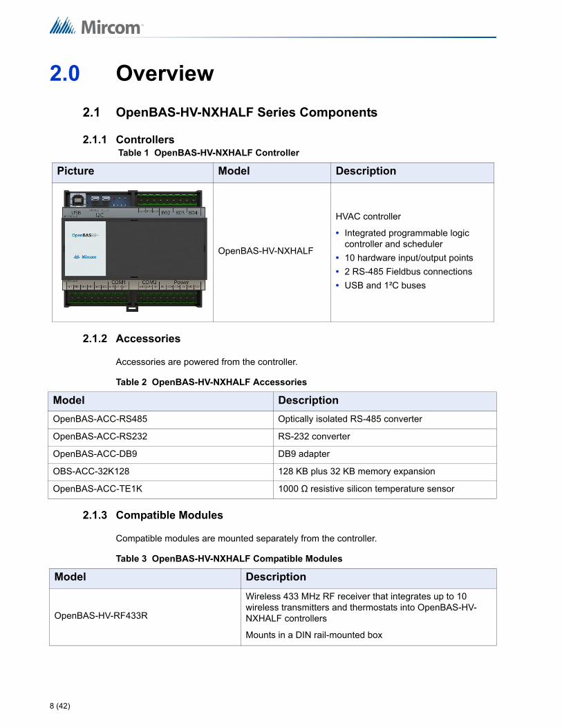
Table 1 OpenBAS-HV-NXHALF Controller
Picture Model Description
OpenBAS-HV-NXHALF
HVAC controller
• Integrated programmable logic controller and scheduler
• 10 hardware input/output points
• 2 RS-485 Fieldbus connections
• USB and 1²C buses
Table 2 OpenBAS-HV-NXHALF Accessories
Model Description
OpenBAS-ACC-RS485 Optically isolated RS-485 converter
OpenBAS-ACC-RS232 RS-232 converter
OpenBAS-ACC-DB9 DB9 adapter
OBS-ACC-32K128 128 KB plus 32 KB memory expansion
OpenBAS-ACC-TE1K 1000 Ω resistive silicon temperature sensor
Table 3 OpenBAS-HV-NXHALF Compatible Modules
Model Description
OpenBAS-HV-RF433R
Wireless 433 MHz RF receiver that integrates up to 10 wireless transmitters and thermostats into OpenBAS-HV-NXHALF controllers
Mounts in a DIN rail-mounted box
3.0 Installation
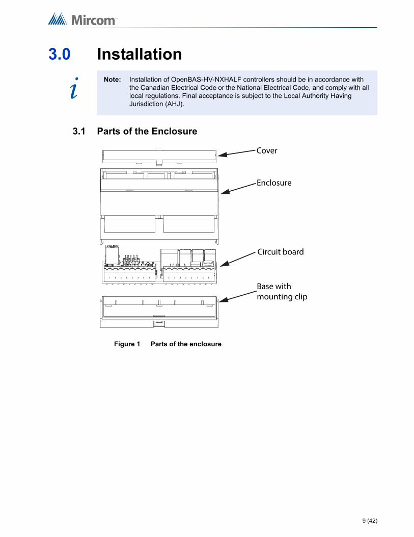
3.1 Parts of the Enclosure
Figure 1 Parts of the enclosure
Note: Installation of OpenBAS-HV-NXHALF controllers should be in accordance with the Canadian Electrical Code or the National Electrical Code, and comply with all local regulations. Final acceptance is subject to the Local Authority Having Jurisdiction (AHJ).
i
Circuit board
Base with mounting clip
Enclosure
Cover
9 (42)
Installation
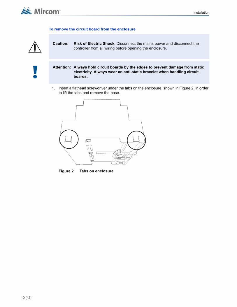
To remove the circuit board from the enclosure
1. Insert a flathead screwdriver under the tabs on the enclosure, shown in Figure 2, in order to lift the tabs and remove the base.
Figure 2 Tabs on enclosure
Caution: Risk of Electric Shock. Disconnect the mains power and disconnect the controller from all wiring before opening the enclosure.
Attention: Always hold circuit boards by the edges to prevent damage from static electricity. Always wear an anti-static bracelet when handling circuit boards.!
10 (42)
Installation
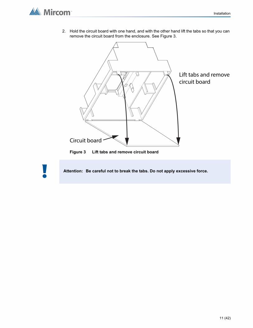
2. Hold the circuit board with one hand, and with the other hand lift the tabs so that you can remove the circuit board from the enclosure. See Figure 3.
Figure 3 Lift tabs and remove circuit board
Attention: Be careful not to break the tabs. Do not apply excessive force.
Lift tabs and remove circuit board
Circuit board
!
11 (42)
Installation
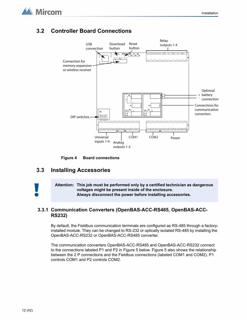
3.2 Controller Board Connections
Figure 4 Board connections
3.3 Installing Accessories
3.3.1 Communication Converters (OpenBAS-ACC-RS485, OpenBAS-ACC-RS232)
By default, the Fieldbus communication terminals are configured as RS-485 through a factory-installed module. They can be changed to RS-232 or optically isolated RS-485 by installing the OpenBAS-ACC-RS232 or OpenBAS-ACC-RS485 converter.
The communication converters OpenBAS-ACC-RS485 and OpenBAS-ACC-RS232 connect to the connections labeled P1 and P2 in Figure 5 below. Figure 5 also shows the relationship between the 2 P connections and the Fieldbus connections (labeled COM1 and COM2). P1 controls COM1 and P2 controls COM2.
Attention: This job must be performed only by a certified technician as dangerous voltages might be present inside of the enclosure.Always disconnect the power before installing accessories.
Universal inputs 1-4
PowerAnalog outputs 1-2
Relay outputs 1-4
Connections for communication converters
USB connection
Connection for memory expansion or wireless receiver
Reset button
Download button
DIP switches
COM1 COM2
Optional battery connection
+-
!
12 (42)
Installation
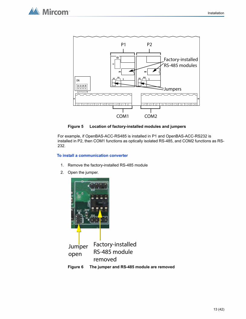
Figure 5 Location of factory-installed modules and jumpers
For example, if OpenBAS-ACC-RS485 is installed in P1 and OpenBAS-ACC-RS232 is installed in P2, then COM1 functions as optically isolated RS-485, and COM2 functions as RS-232.
To install a communication converter
1. Remove the factory-installed RS-485 module
2. Open the jumper.
Figure 6 The jumper and RS-485 module are removed
COM1
P1
COM2
P2
Factory-installed RS-485 modules
Jumpers
Jumper open
Factory-installed RS-485 module removed
13 (42)
Installation
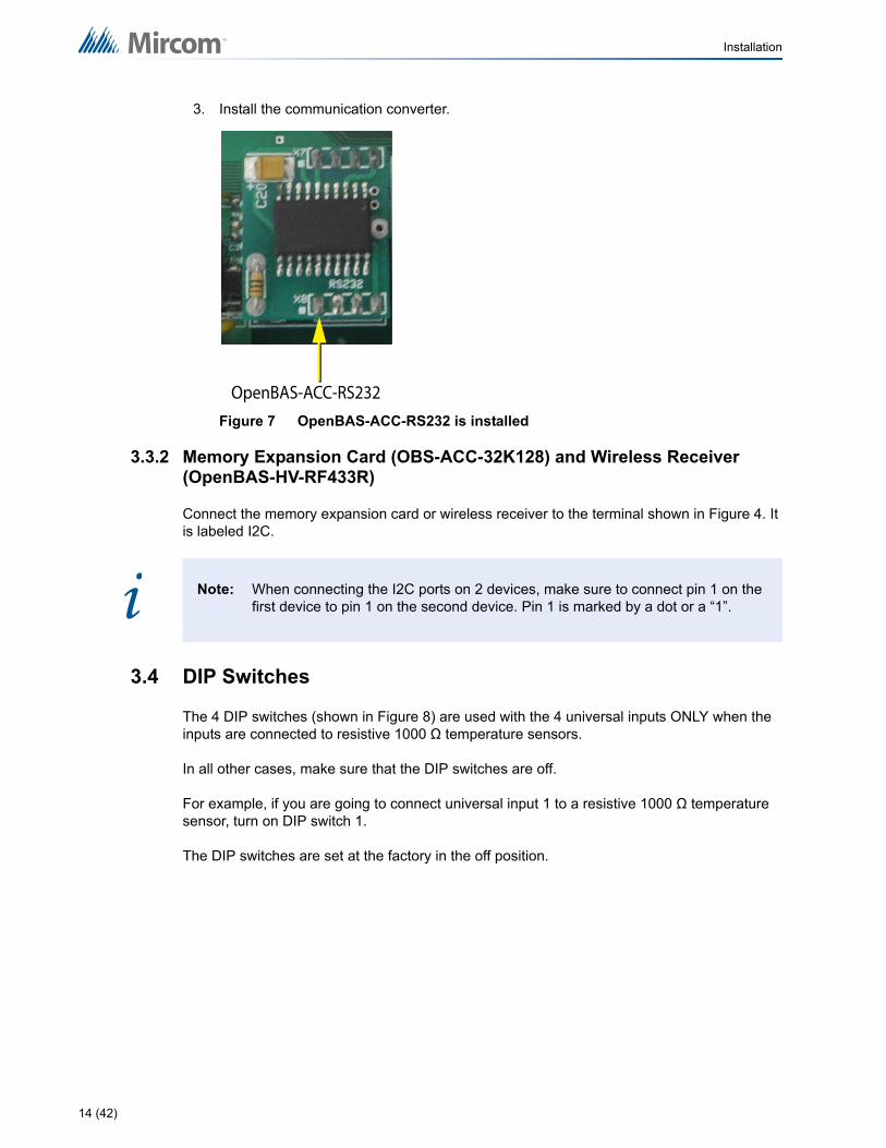
3. Install the communication converter.
Figure 7 OpenBAS-ACC-RS232 is installed
3.3.2 Memory Expansion Card (OBS-ACC-32K128) and Wireless Receiver (OpenBAS-HV-RF433R)
Connect the memory expansion card or wireless receiver to the terminal shown in Figure 4. It is labeled I2C.
3.4 DIP Switches
The 4 DIP switches (shown in Figure 8) are used with the 4 universal inputs ONLY when the inputs are connected to resistive 1000 Ω temperature sensors.
In all other cases, make sure that the DIP switches are off.
For example, if you are going to connect universal input 1 to a resistive 1000 Ω temperature sensor, turn on DIP switch 1.
The DIP switches are set at the factory in the off position.
Note: When connecting the I2C ports on 2 devices, make sure to connect pin 1 on the first device to pin 1 on the second device. Pin 1 is marked by a dot or a “1”.
OpenBAS-ACC-RS232
i
14 (42)
Installation
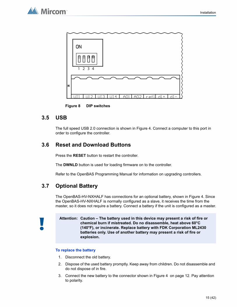
Figure 8 DIP switches
3.5 USB
The full speed USB 2.0 connection is shown in Figure 4. Connect a computer to this port in order to configure the controller.
3.6 Reset and Download Buttons
Press the RESET button to restart the controller.
The DWNLD button is used for loading firmware on to the controller.
Refer to the OpenBAS Programming Manual for information on upgrading controllers.
3.7 Optional Battery
The OpenBAS-HV-NXHALF has connections for an optional battery, shown in Figure 4. Since the OpenBAS-HV-NXHALF is normally configured as a slave, it receives the time from the master, so it does not require a battery. Connect a battery if the unit is configured as a master.
To replace the battery
1. Disconnect the old battery.
2. Dispose of the used battery promptly. Keep away from children. Do not disassemble and do not dispose of in fire.
3. Connect the new battery to the connector shown in Figure 4 on page 12. Pay attention to polarity.
Attention: Caution – The battery used in this device may present a risk of fire or chemical burn if mistreated. Do no disassemble, heat above 60°C (140°F), or incinerate. Replace battery with FDK Corporation ML2430 batteries only. Use of another battery may present a risk of fire or explosion.
1 2 3 4
!
15 (42)
Installation
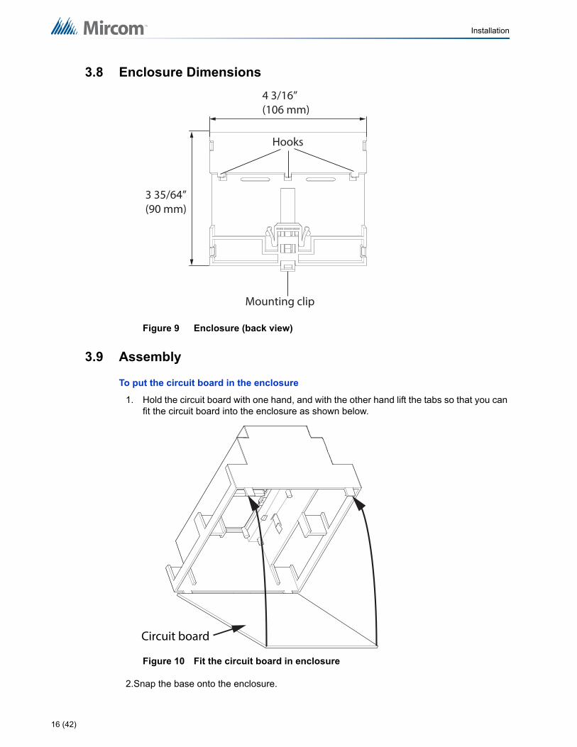
3.8 Enclosure Dimensions
Figure 9 Enclosure (back view)
3.9 Assembly
To put the circuit board in the enclosure
1. Hold the circuit board with one hand, and with the other hand lift the tabs so that you can fit the circuit board into the enclosure as shown below.
Figure 10 Fit the circuit board in enclosure
2.Snap the base onto the enclosure.
3 35/64” (90 mm)
4 3/16” (106 mm)
Mounting clip
Hooks
Circuit board
16 (42)
Installation
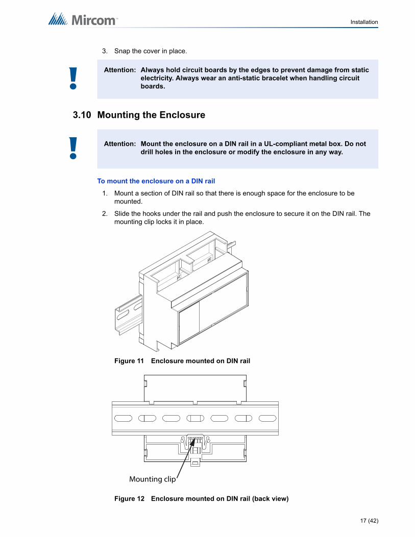
3. Snap the cover in place.
3.10 Mounting the Enclosure
To mount the enclosure on a DIN rail
1. Mount a section of DIN rail so that there is enough space for the enclosure to be mounted.
2. Slide the hooks under the rail and push the enclosure to secure it on the DIN rail. The mounting clip locks it in place.
Figure 11 Enclosure mounted on DIN rail
Figure 12 Enclosure mounted on DIN rail (back view)
Attention: Always hold circuit boards by the edges to prevent damage from static electricity. Always wear an anti-static bracelet when handling circuit boards.
Attention: Mount the enclosure on a DIN rail in a UL-compliant metal box. Do not drill holes in the enclosure or modify the enclosure in any way.
!
!
Mounting clip
17 (42)

Installation
To remove the enclosure from the DIN rail
• With your hands or with a small flathead screwdriver, pull the mounting clip to release the enclosure from the DIN rail, and carefully pull the enclosure off the DIN rail.
18 (42)

4.0 Field Wiring
4.1 To Wire the Terminals
Figure 4 on page 12 shows the location of the terminals. The terminals are depluggable for ease of wiring.
4.1.1 Required Tools
Tools needed:
• Precision or jeweler's screwdriver set
• Wire cutter
• Wire stripper
4.1.2 Installation Tips
• Perform visual inspection of circuit board and parts for obvious issues.
• Use a wire tie to group wires for easy identification and neatness.
4.2 Power Supply Connection
The OpenBAS-HV-NXHALF controller can be powered 3 different ways.
• 12 Vdc, 177 mA max.
• 24 Vac 50/60 Hz, 200 mA max.
• 24 Vdc, 102 mA max.
Note: Installation of OpenBAS-HV-NXHALF controllers must be in accordance with the Canadian Electrical Code or the National Electrical Code, and comply with all local regulations. Final acceptance is subject to the Local Authority Having Jurisdiction (AHJ).
Caution: An appropriate UL listed class 2 power supply or transformer with necessary protection devices such as fuses or breakers should be used to limit the risk of fire. All local codes and regulations for installation must be observed.
i
!
19 (42)
Field Wiring
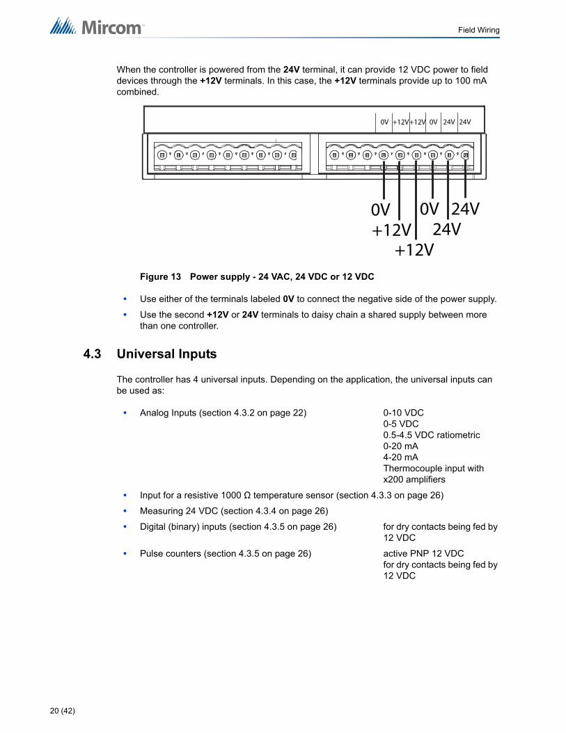
When the controller is powered from the 24V terminal, it can provide 12 VDC power to field devices through the +12V terminals. In this case, the +12V terminals provide up to 100 mA combined.
Figure 13 Power supply - 24 VAC, 24 VDC or 12 VDC
• Use either of the terminals labeled 0V to connect the negative side of the power supply.
• Use the second +12V or 24V terminals to daisy chain a shared supply between more than one controller.
4.3 Universal Inputs
The controller has 4 universal inputs. Depending on the application, the universal inputs can be used as:
• Analog Inputs (section 4.3.2 on page 22) 0-10 VDC0-5 VDC0.5-4.5 VDC ratiometric0-20 mA4-20 mAThermocouple input withx200 amplifiers
• Input for a resistive 1000 Ω temperature sensor (section 4.3.3 on page 26)
• Measuring 24 VDC (section 4.3.4 on page 26)
• Digital (binary) inputs (section 4.3.5 on page 26) for dry contacts being fed by 12 VDC
• Pulse counters (section 4.3.5 on page 26) active PNP 12 VDCfor dry contacts being fed by 12 VDC
0V 24V 24V
0V24V
24V
0V +12V+12V
0V+12V
+12V
20 (42)

Field Wiring
Figure 14 Universal Inputs
4.3.1 Tips for Universal Inputs
• Use 18 AWG stranded wire.
• The absolute maximum voltage is 15 VDC.
• Fit the end of the wire with terminal connectors to provide a solid connection that can withstand temperature changes and vibration without becoming loose.
• Connect the common wires of sensors to the 0V terminals. Use either of the 0V terminals to connect the common wires of sensors.
• Turn the corresponding DIP switch on ONLY when using resistive 1000 Ω temperature sensors. See section 3.4 on page 14.
• When using 2 or more external power supplies, connect the negatives or commons of both power supplies to the 0V terminal of the controller.
To ensure that the universal inputs operate correctly, follow these guidelines:
• Limit the distance between the analog sensor and the controller to 10 m (30 ft). Mircom recommends shielded wire for noisy environments.
• If this distance is not possible, longer wire runs with shielded wire are allowed up to 30 m (100 ft). Connect the shield to any 0V terminal on the controller, making sure to isolate the shield on the other end. Failing to do so creates ground loops.
• When possible, route the wiring inside metal piping and ground the piping for better results.
• Avoid running any analog signals near sources of electric noise such as: motors, ballasts, fluorescent lamps, variable frequency drives, high energy contacts, RF (radio frequency) transmitters, microwave ovens, and any other equipment that generates electromagnetic interference.
• Keep a minimum distance of 30 cm (1 ft) between analog input wiring and any conductor carrying more than 24 VAC.
• Follow good wiring and installation practices, and follow all local regulations and electrical codes.
UI4
UI4
UI1 UI2 UI3
UI1UI2
UI3
21 (42)
Field Wiring
4.3.2 Analog Inputs
Connect any sensor or transducer that outputs 0-5 V, 0.5-4.5 V ratiometric, or 0-10 V directly to the universal inputs when they are configured as analog inputs.
To use the universal inputs as analog inputs
1. Connect the appropriate analog signal to the universal input according to the diagrams below.
2. Configure the analog input type and then calibrate using the OpenBAS software.
Terminal Labeling on Field Devices
The positive terminal on field devices might be labeled one of the following:
The negative terminal on field devices might be labeled one of the following:
Table 4 shows how to connect different devices to the analog inputs.
+ +24 +PWR 24 +DC AC PWR
- 0V GND Neg COM
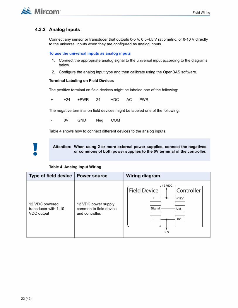
Attention: When using 2 or more external power supplies, connect the negativesor commons of both power supplies to the 0V terminal of the controller.
Table 4 Analog Input Wiring
Type of field device Power source Wiring diagram
12 VDC powered transducer with 1-10 VDC output
12 VDC power supply common to field device and controller.
!
UI#
12 VDC
0 V
Field Device+
Signal
-
+12V
0V
Controller
22 (42)
Field Wiring
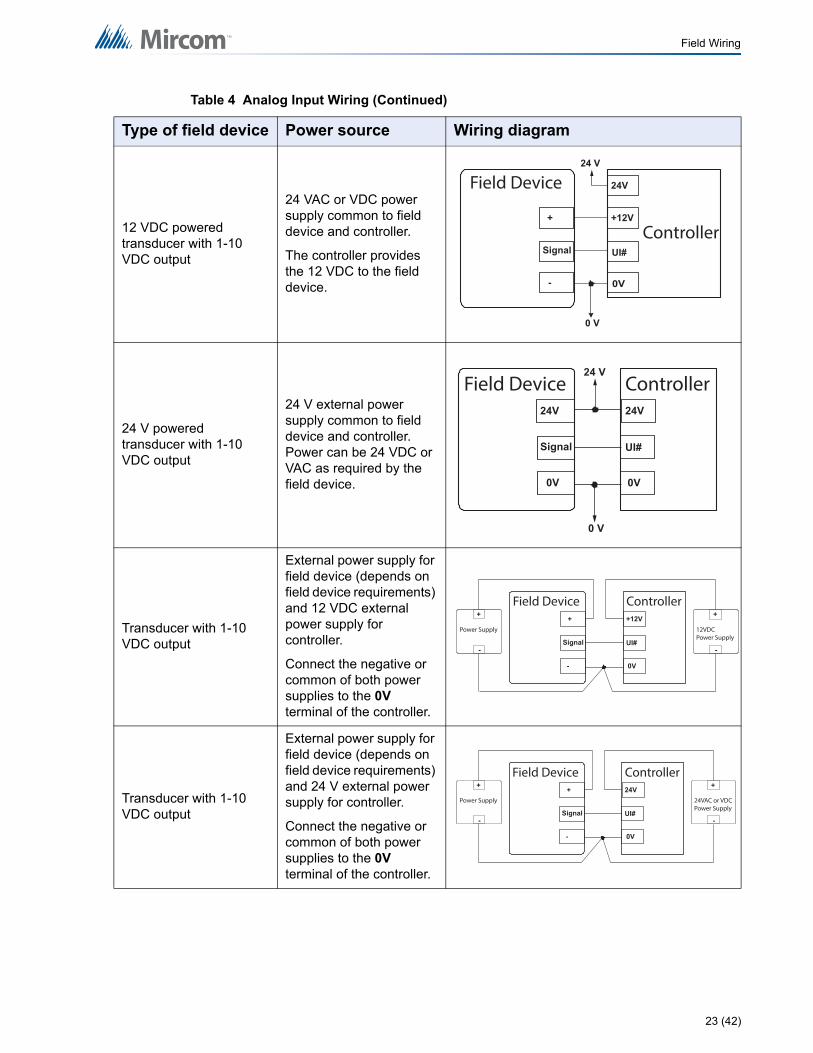
12 VDC powered transducer with 1-10 VDC output
24 VAC or VDC power supply common to field device and controller.
The controller provides the 12 VDC to the field device.
24 V powered transducer with 1-10 VDC output
24 V external power supply common to field device and controller. Power can be 24 VDC or VAC as required by the field device.
Transducer with 1-10 VDC output
External power supply for field device (depends on field device requirements) and 12 VDC external power supply for controller.
Connect the negative or common of both power supplies to the 0V terminal of the controller.
Transducer with 1-10 VDC output
External power supply for field device (depends on field device requirements) and 24 V external power supply for controller.
Connect the negative or common of both power supplies to the 0V terminal of the controller.
Table 4 Analog Input Wiring (Continued)
Type of field device Power source Wiring diagram
UI#
0V
24 V
0 V
Field Device
+
Signal
-
+12V
24V
Controller
UI#
0 V
24V
Signal
0V
24V
0V
24 VField Device Controller
UI#
+
Signal
-
+12V
0V
Field Device Controller
Power Supply
+
-
12VDCPower Supply
+
-
UI#
+
Signal
-
24V
0V
Field Device Controller
Power Supply
+
-
24VAC or VDCPower Supply
+
-
23 (42)
Field Wiring
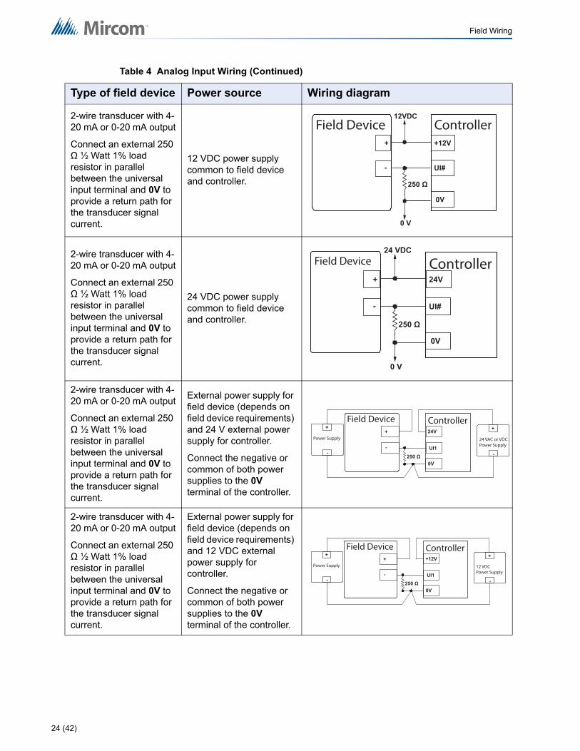
2-wire transducer with 4-20 mA or 0-20 mA output
Connect an external 250 Ω ½ Watt 1% load resistor in parallel between the universal input terminal and 0V to provide a return path for the transducer signal current.
12 VDC power supply common to field device and controller.
2-wire transducer with 4-20 mA or 0-20 mA output
Connect an external 250 Ω ½ Watt 1% load resistor in parallel between the universal input terminal and 0V to provide a return path for the transducer signal current.
24 VDC power supply common to field device and controller.
2-wire transducer with 4-20 mA or 0-20 mA output
Connect an external 250 Ω ½ Watt 1% load resistor in parallel between the universal input terminal and 0V to provide a return path for the transducer signal current.
External power supply for field device (depends on field device requirements) and 24 V external power supply for controller.
Connect the negative or common of both power supplies to the 0V terminal of the controller.
2-wire transducer with 4-20 mA or 0-20 mA output
Connect an external 250 Ω ½ Watt 1% load resistor in parallel between the universal input terminal and 0V to provide a return path for the transducer signal current.
External power supply for field device (depends on field device requirements) and 12 VDC external power supply for controller.
Connect the negative or common of both power supplies to the 0V terminal of the controller.
Table 4 Analog Input Wiring (Continued)
Type of field device Power source Wiring diagram
UI#
0 V
+
-
+12V
0V
12VDCField Device Controller
UI#
0 V
Field Device
+
-
24V
0V
24 VDC
Controller
24V
0V
UI1
Controller
Power Supply
+
-
24 VAC or VDCPower Supply
+
-
+
-
Field Device
+12V
0V
UI1
Controller
Power Supply
+
-
12 VDCPower Supply
+
-
+
-
Field Device
24 (42)
Field Wiring
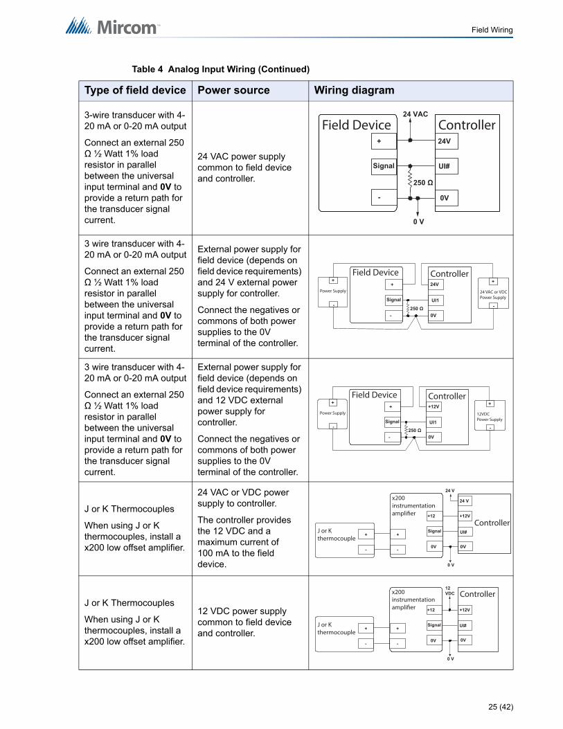
3-wire transducer with 4-20 mA or 0-20 mA output
Connect an external 250 Ω ½ Watt 1% load resistor in parallel between the universal input terminal and 0V to provide a return path for the transducer signal current.
24 VAC power supply common to field device and controller.
3 wire transducer with 4-20 mA or 0-20 mA output
Connect an external 250 Ω ½ Watt 1% load resistor in parallel between the universal input terminal and 0V to provide a return path for the transducer signal current.
External power supply for field device (depends on field device requirements) and 24 V external power supply for controller.
Connect the negatives or commons of both power supplies to the 0V terminal of the controller.
3 wire transducer with 4-20 mA or 0-20 mA output
Connect an external 250 Ω ½ Watt 1% load resistor in parallel between the universal input terminal and 0V to provide a return path for the transducer signal current.
External power supply for field device (depends on field device requirements) and 12 VDC external power supply for controller.
Connect the negatives or commons of both power supplies to the 0V terminal of the controller.
J or K Thermocouples
When using J or K thermocouples, install a x200 low offset amplifier.
24 VAC or VDC power supply to controller.
The controller provides the 12 VDC and a maximum current of 100 mA to the field device.
J or K Thermocouples
When using J or K thermocouples, install a x200 low offset amplifier.
12 VDC power supply common to field device and controller.
Table 4 Analog Input Wiring (Continued)
Type of field device Power source Wiring diagram
UI#
0 V
+
Signal
24V
0V
24 VAC
-
Field Device Controller
24V
0V
UI1
Controller
Power Supply
+
-
24 VAC or VDCPower Supply
+
-
+
Signal
-
Field Device
+12V
0V
UI1
Controller
Power Supply
+
-
12VDCPower Supply
+
-
+
Signal
-
Field Device
+12
Signal
0V
J or K thermocouple
+
-
+
-
x200 instrumentation amplifier
UI#
0V
24 V
0 V
+12V
24 V
Controller
+12
Signal
0V
J or K thermocouple
+
-
+
-
x200 instrumentation amplifier
0 V
12 VDC
UI#
+12V
0V
Controller
25 (42)
Field Wiring
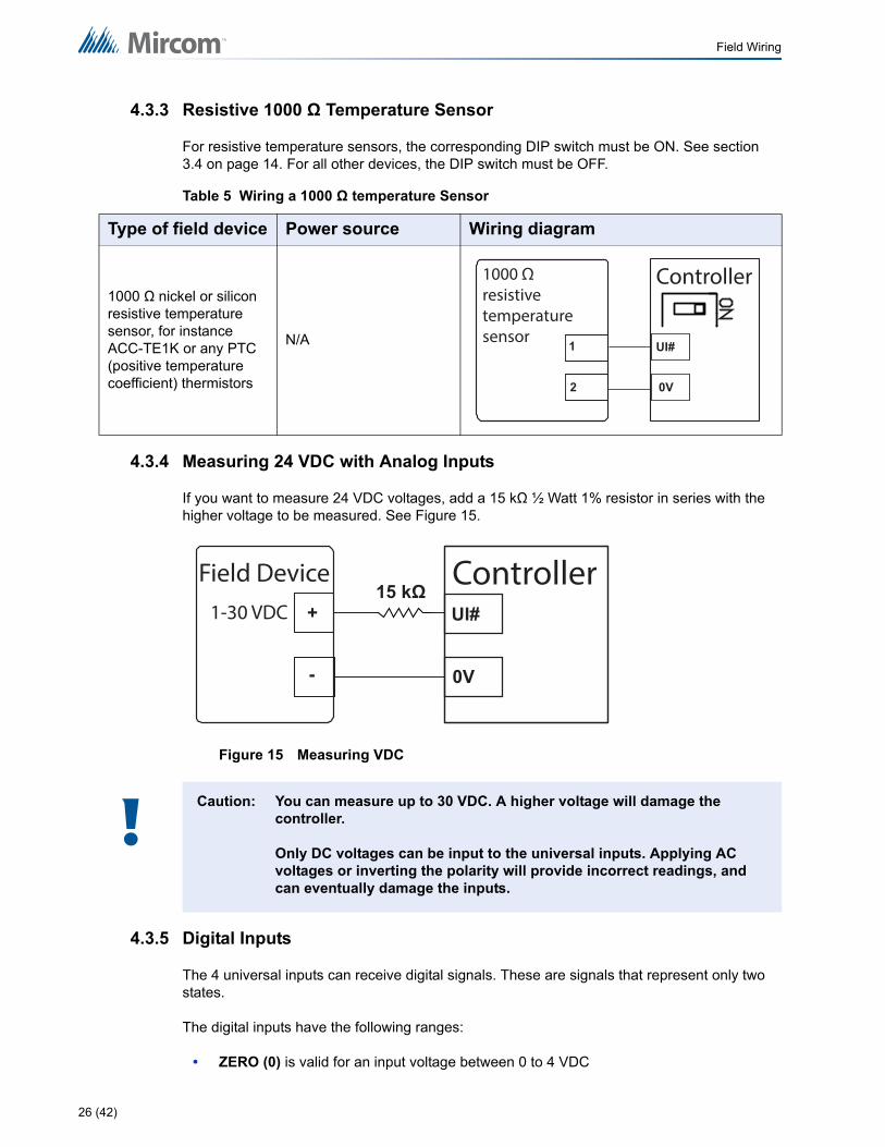
4.3.3 Resistive 1000 Ω Temperature Sensor
For resistive temperature sensors, the corresponding DIP switch must be ON. See section 3.4 on page 14. For all other devices, the DIP switch must be OFF.
4.3.4 Measuring 24 VDC with Analog Inputs
If you want to measure 24 VDC voltages, add a 15 kΩ ½ Watt 1% resistor in series with the higher voltage to be measured. See Figure 15.
Figure 15 Measuring VDC
4.3.5 Digital Inputs
The 4 universal inputs can receive digital signals. These are signals that represent only two states.
The digital inputs have the following ranges:
• ZERO (0) is valid for an input voltage between 0 to 4 VDC
Table 5 Wiring a 1000 Ω temperature Sensor
Type of field device Power source Wiring diagram
1000 Ω nickel or silicon resistive temperature sensor, for instance ACC-TE1K or any PTC (positive temperature coefficient) thermistors
N/A
Caution: You can measure up to 30 VDC. A higher voltage will damage the controller.
Only DC voltages can be input to the universal inputs. Applying AC voltages or inverting the polarity will provide incorrect readings, and can eventually damage the inputs.
UI#1
2 0V
1000 Ω resistive temperature sensor
Controller
0V
UI#
Field Device+
-
1-30 VDC
Controller
!
26 (42)
Field Wiring
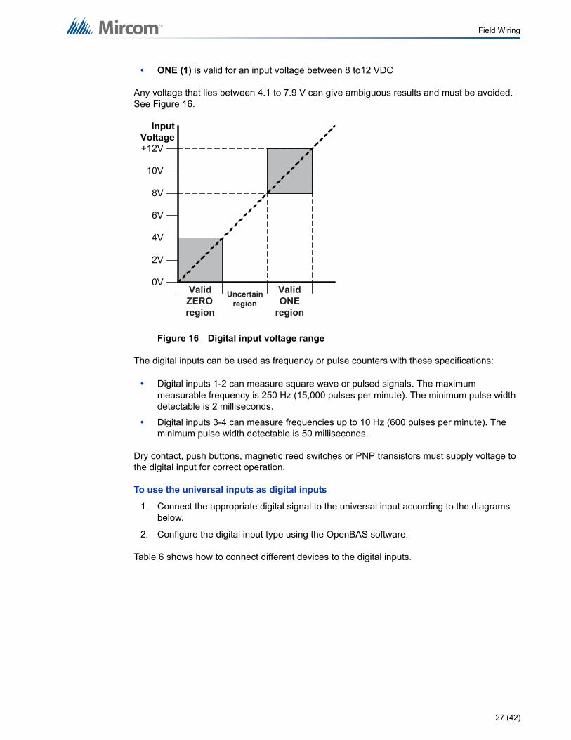
• ONE (1) is valid for an input voltage between 8 to12 VDC
Any voltage that lies between 4.1 to 7.9 V can give ambiguous results and must be avoided. See Figure 16.
Figure 16 Digital input voltage range
The digital inputs can be used as frequency or pulse counters with these specifications:
• Digital inputs 1-2 can measure square wave or pulsed signals. The maximum measurable frequency is 250 Hz (15,000 pulses per minute). The minimum pulse width detectable is 2 milliseconds.
• Digital inputs 3-4 can measure frequencies up to 10 Hz (600 pulses per minute). The minimum pulse width detectable is 50 milliseconds.
Dry contact, push buttons, magnetic reed switches or PNP transistors must supply voltage to the digital input for correct operation.
To use the universal inputs as digital inputs
1. Connect the appropriate digital signal to the universal input according to the diagrams below.
2. Configure the digital input type using the OpenBAS software.
Table 6 shows how to connect different devices to the digital inputs.
InputVoltage
0V
2V
4V
6V
8V
10V
+12V
ValidZEROregion
ValidONE
region
Uncertainregion
27 (42)
Field Wiring
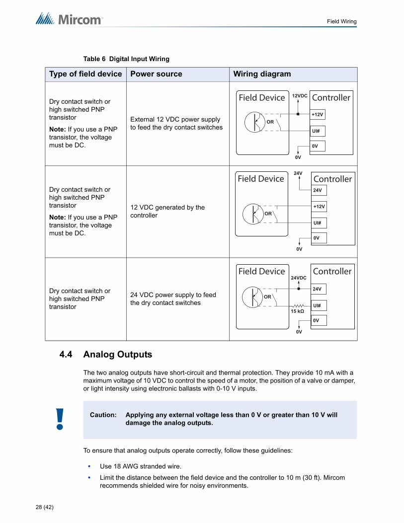
4.4 Analog Outputs
The two analog outputs have short-circuit and thermal protection. They provide 10 mA with a maximum voltage of 10 VDC to control the speed of a motor, the position of a valve or damper, or light intensity using electronic ballasts with 0-10 V inputs.
To ensure that analog outputs operate correctly, follow these guidelines:
• Use 18 AWG stranded wire.
• Limit the distance between the field device and the controller to 10 m (30 ft). Mircom recommends shielded wire for noisy environments.
Table 6 Digital Input Wiring
Type of field device Power source Wiring diagram
Dry contact switch or high switched PNP transistor
Note: If you use a PNP transistor, the voltage must be DC.
External 12 VDC power supply to feed the dry contact switches
Dry contact switch or high switched PNP transistor
Note: If you use a PNP transistor, the voltage must be DC.
12 VDC generated by the controller
Dry contact switch or high switched PNP transistor
24 VDC power supply to feed the dry contact switches
Caution: Applying any external voltage less than 0 V or greater than 10 V will damage the analog outputs.
UI#
+12V
Field Device Controller
0V
12VDC
0V
OR
UI#
24V
24V
+12V
Field Device Controller
0V
0V
OR
UI#
24V
Field Device24VDC
Controller
0V
0V
OR
!
28 (42)
Field Wiring
• If this distance is not possible, longer wire runs with shielded wire are allowed up to 30 m (100 ft). Connect the shield to any 0V terminal on the controller, making sure to isolate the shield on the other end. Failing to do so creates ground loops.
• When possible, route the wiring inside metal piping and ground the piping for better results.
• Avoid running any analog signals near sources of electric noise such as: motors, ballasts, fluorescent lamps, variable frequency drives, high energy contacts, RF (radio frequency) transmitters, microwave ovens, and any other equipment that generates electromagnetic interference.
• Keep a minimum distance of 30 cm (1 ft) between analog output wiring and any conductor carrying more than 24 VAC.
• Follow good wiring and installation practices, and follow all local regulations and electrical codes.
• Use either of the terminals labeled 0V to connect the return signal or common.
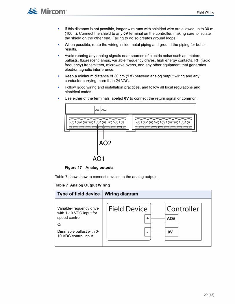
Figure 17 Analog outputs
Table 7 shows how to connect devices to the analog outputs.
Table 7 Analog Output Wiring
Type of field device Wiring diagram
Variable-frequency drive with 1-10 VDC input for speed control
Or
Dimmable ballast with 0-10 VDC control input
AO2
AO2
AO1
AO1
AO#+
- 0V
Field Device Controller
29 (42)
Field Wiring
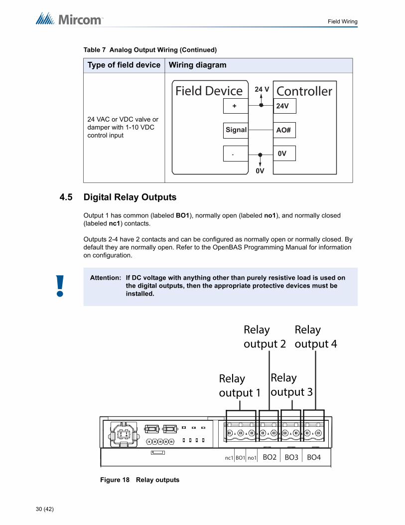
4.5 Digital Relay Outputs
Output 1 has common (labeled BO1), normally open (labeled no1), and normally closed (labeled nc1) contacts.
Outputs 2-4 have 2 contacts and can be configured as normally open or normally closed. By default they are normally open. Refer to the OpenBAS Programming Manual for information on configuration.
Figure 18 Relay outputs
24 VAC or VDC valve or damper with 1-10 VDC control input
Attention: If DC voltage with anything other than purely resistive load is used on the digital outputs, then the appropriate protective devices must be installed.
Table 7 Analog Output Wiring (Continued)
Type of field device Wiring diagram
AO#
+
Signal
-
24V
0V
Field Device
0V
Controller24 V
!
BO2BO1 no1nc1
Relay output 1
BO3 BO4
Relay output 2
Relay output 3
Relay output 4
30 (42)
Field Wiring
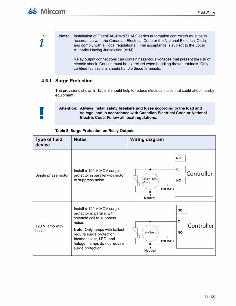
4.5.1 Surge Protection
The provisions shown in Table 8 should help to reduce electrical noise that could affect nearby equipment.
Note: Installation of OpenBAS-HV-NXHALF series automation controllers must be in accordance with the Canadian Electrical Code or the National Electrical Code, and comply with all local regulations. Final acceptance is subject to the Local Authority Having Jurisdiction (AHJ).
Relay output connections can contain hazardous voltages that present the risk of electric shock. Caution must be exercised when handling these terminals. Only certified technicians should handle these terminals.
Attention: Always install safety breakers and fuses according to the load and voltage, and in accordance with Canadian Electrical Code or National Electric Code. Follow all local regulations.
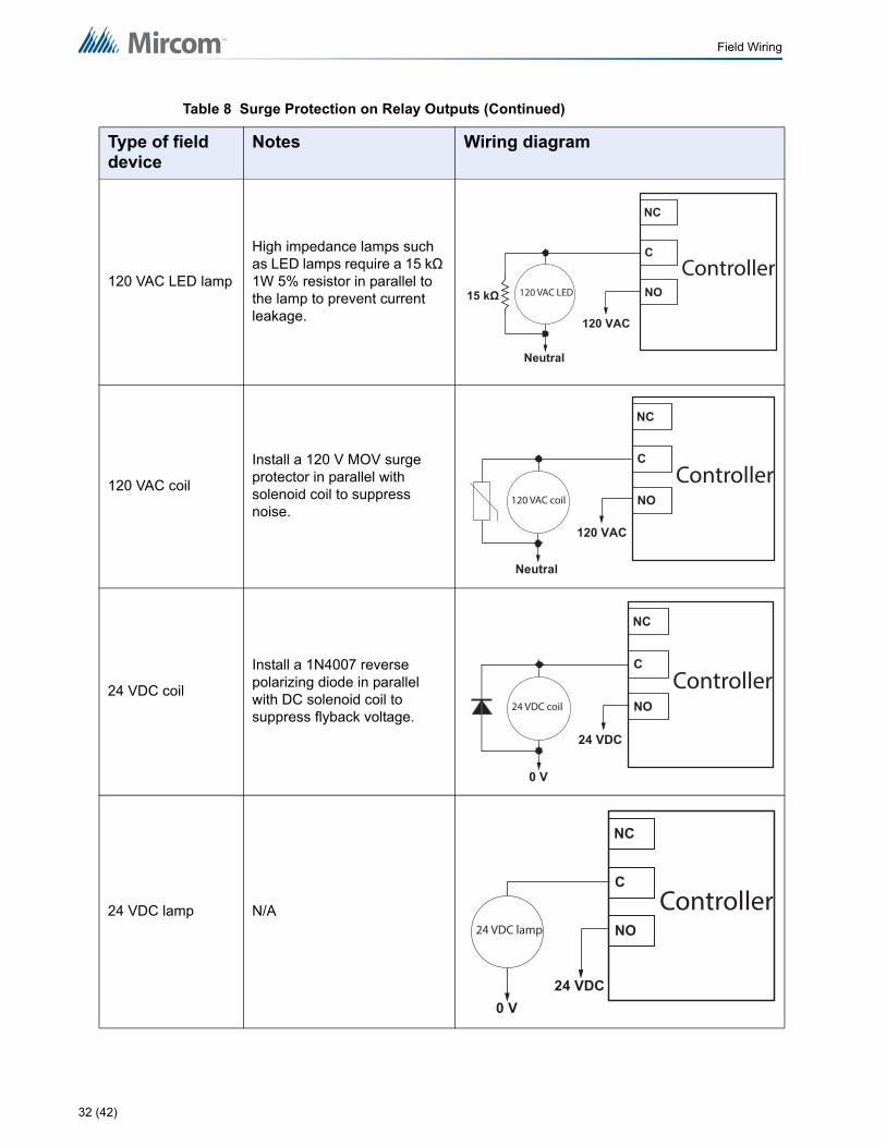
Table 8 Surge Protection on Relay Outputs
Type of field device
Notes Wiring diagram
Single phase motorInstall a 120 V MOV surge protector in parallel with motor to suppress noise.
120 V lamp with ballast
Install a 120 V MOV surge protector in parallel with solenoid coil to suppress noise.
Note: Only lamps with ballast require surge protection. Incandescent, LED, and halogen lamps do not require surge protection.
i
!
Single Phase Motor
NO
NC
C
120 VAC
Neutral
Controller
120 V lamp
120 VAC
Neutral
NO
NC
CController
31 (42)
Field Wiring
120 VAC LED lamp
High impedance lamps such as LED lamps require a 15 kΩ 1W 5% resistor in parallel to the lamp to prevent current leakage.
120 VAC coil
Install a 120 V MOV surge protector in parallel with solenoid coil to suppress noise.
24 VDC coil
Install a 1N4007 reverse polarizing diode in parallel with DC solenoid coil to suppress flyback voltage.
24 VDC lamp N/A
Table 8 Surge Protection on Relay Outputs (Continued)
Type of field device
Notes Wiring diagram
120 VAC LED
120 VAC
Neutral
NO
NC
CController
120 VAC coil
120 VAC
Neutral
NO
NC
CController
24 VDC coil
C
24 VDC
0 V
NO
NC
Controller
24 VDC lamp
24 VDC0 V
C
NO
NC
Controller
32 (42)
Field Wiring
4.6 Fieldbus Connections and OpenBAS-ACC-DB9
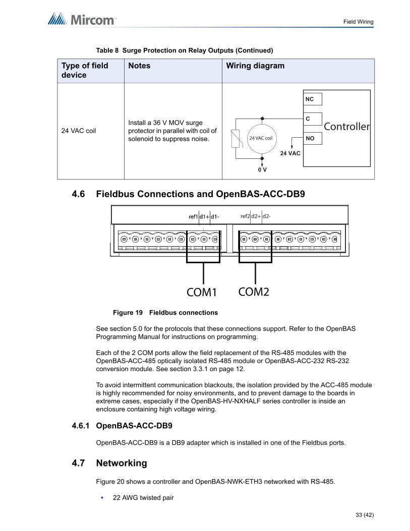
Figure 19 Fieldbus connections
See section 5.0 for the protocols that these connections support. Refer to the OpenBAS Programming Manual for instructions on programming.
Each of the 2 COM ports allow the field replacement of the RS-485 modules with the OpenBAS-ACC-485 optically isolated RS-485 module or OpenBAS-ACC-232 RS-232 conversion module. See section 3.3.1 on page 12.
To avoid intermittent communication blackouts, the isolation provided by the ACC-485 module is highly recommended for noisy environments, and to prevent damage to the boards in extreme cases, especially if the OpenBAS-HV-NXHALF series controller is inside an enclosure containing high voltage wiring.
4.6.1 OpenBAS-ACC-DB9
OpenBAS-ACC-DB9 is a DB9 adapter which is installed in one of the Fieldbus ports.
4.7 Networking
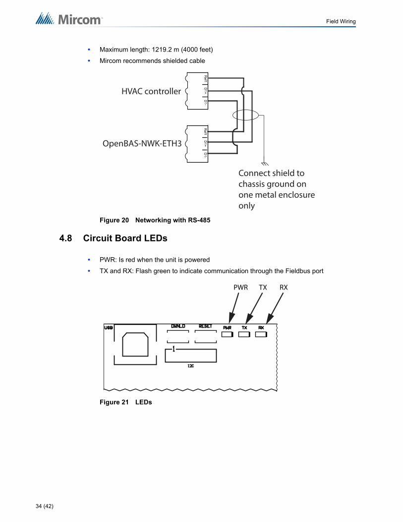
Figure 20 shows a controller and OpenBAS-NWK-ETH3 networked with RS-485.
• 22 AWG twisted pair
24 VAC coilInstall a 36 V MOV surge protector in parallel with coil of solenoid to suppress noise.
Table 8 Surge Protection on Relay Outputs (Continued)
Type of field device
Notes Wiring diagram
24 VAC coil
24 VAC
0 V
C
NO
NC
Controller
d1+ref1 d1-
COM1
d1+ref1 d1- d2+ref2 d2-
COM2
33 (42)
Field Wiring
• Maximum length: 1219.2 m (4000 feet)
• Mircom recommends shielded cable
Figure 20 Networking with RS-485
4.8 Circuit Board LEDs
• PWR: Is red when the unit is powered
• TX and RX: Flash green to indicate communication through the Fieldbus port
Figure 21 LEDs
HVAC controller
OpenBAS-NWK-ETH3
Connect shield to chassis ground on one metal enclosure only
PWR TX RX
34 (42)
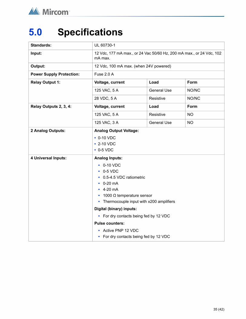
5.0 SpecificationsStandards: UL 60730-1
Input: 12 Vdc, 177 mA max., or 24 Vac 50/60 Hz, 200 mA max., or 24 Vdc, 102 mA max.
Output: 12 Vdc, 100 mA max. (when 24V powered)
Power Supply Protection: Fuse 2.0 A
Relay Output 1: Voltage, current Load Form
125 VAC, 5 A General Use NO/NC
28 VDC, 5 A Resistive NO/NC
Relay Outputs 2, 3, 4: Voltage, current Load Form
125 VAC, 5 A Resistive NO
125 VAC, 3 A General Use NO
2 Analog Outputs: Analog Output Voltage:
• 0-10 VDC
• 2-10 VDC
• 0-5 VDC
4 Universal Inputs: Analog Inputs:
• 0-10 VDC
• 0-5 VDC
• 0.5-4.5 VDC ratiometric
• 0-20 mA
• 4-20 mA
• 1000 Ω temperature sensor
• Thermocouple input with x200 amplifiers
Digital (binary) inputs:
• For dry contacts being fed by 12 VDC
Pulse counters:
• Active PNP 12 VDC
• For dry contacts being fed by 12 VDC
35 (42)
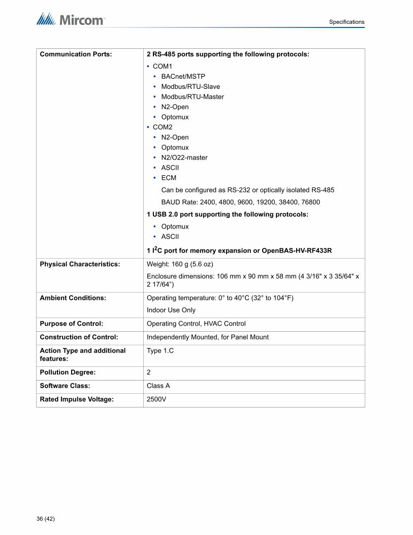
Specifications
Communication Ports: 2 RS-485 ports supporting the following protocols:
• COM1
• BACnet/MSTP
• Modbus/RTU-Slave
• Modbus/RTU-Master
• N2-Open
• Optomux
• COM2
• N2-Open
• Optomux
• N2/O22-master
• ASCII
• ECM
Can be configured as RS-232 or optically isolated RS-485
BAUD Rate: 2400, 4800, 9600, 19200, 38400, 76800
1 USB 2.0 port supporting the following protocols:
• Optomux
• ASCII
1 I2C port for memory expansion or OpenBAS-HV-RF433R
Physical Characteristics: Weight: 160 g (5.6 oz)
Enclosure dimensions: 106 mm x 90 mm x 58 mm (4 3/16" x 3 35/64" x 2 17/64”)
Ambient Conditions: Operating temperature: 0° to 40°C (32° to 104°F)
Indoor Use Only
Purpose of Control: Operating Control, HVAC Control
Construction of Control: Independently Mounted, for Panel Mount
Action Type and additional features:
Type 1.C
Pollution Degree: 2
Software Class: Class A
Rated Impulse Voltage: 2500V
36 (42)

6.0 Master Warranty and Warning InformationTerms & Interpretation
In this document the term MGC System refers to all fire alarm, nurse call, and building automation products manufactured by Mircom Group of Companies, Mircom Technologies Ltd., MGC Systems Corp or subsidiaries and affiliates and includes specific systems such as MiCare™, OpenBAS™, and FlexNet™. Moreover, the term MGC System extends to cover all component parts and software used within such products.
Warning Please Read Carefully
All MGC Systems are subject to terms and conditions of sale as follows:
Note to Installers
This warning contains vital information. As the only individual in contact with system users, it is your responsibility to bring each item in this warning to the attention of the users of this MGC System. Failure to properly inform system end-users of the circumstances in which the system might fail may result in over-reliance upon the system. As a result, it is imperative that you properly inform each customer for whom you install the system of the possible forms of failure.
System Failures
All MGC Systems have been carefully designed to be as effective as possible. However, there are circumstances where they may not provide protection. Some reasons for system failure include:
Inadequate Installation
All MGC Systems must be installed in accordance with all the applicable codes and standards in order to provide adequate protection. National standards require an inspection and approval to be conducted by the Local Authority Having Jurisdiction following the initial installation of the system and following any changes to the system. Such inspections ensure installation has been carried out properly.
Inadequate Testing
Most problems that would prevent an alarm a MGC System from operating as intended can be discovered by regular testing and maintenance. The complete system should be tested by the Local Authority Having Jurisdiction immediately after a fire, storm, earthquake, accident, or any kind of construction activity inside or outside the premises. The testing should include all sensing devices, keypads, consoles, alarm indicating devices and any other operational devices that are part of the system.
IMPORTANT NOTE: End-users of the system must take care to ensure that the system, batteries, telephone lines, etc. are tested and examined on a regular basis to minimize system failure.
37 (42)

Master Warranty and Warning Information
System Users
It is important that all system users be trained in the correct operation of the alarm system and that they know how to respond when the system indicates an alarm.
A MGC System may not function as intended during an emergency situation where the user is unable to operate a panic or emergency switch by reason of permanent or temporary physical disability, inability to reach the device in time, unfamiliarity with the correct operation, or related circumstances.
Insufficient Time
There may be circumstances when a MGC System will operate as intended, yet the occupants will not be protected from the emergency due to their inability to respond to the warnings in a timely manner. If the system is monitored, the response may not occur in time enough to protect the occupants or their belongings.
Moreover, smoke detectors may not provide timely warning of fires caused by carelessness or safety hazards such as smoking in bed, violent explosions, escaping gas, improper storage of flammable materials, overloaded electrical circuits, children playing with matches or arson.
Power Failure
Some MGC System components require adequate electrical power supply to operate. Examples include: smoke detectors, beacons, HVAC, and lighting controllers. If a device operates only by AC power, any interruption, however brief, will render that device inoperative while it does not have power. Power interruptions of any length are often accompanied by voltage fluctuations which may damage MGC Systems or other electronic equipment. After a power interruption has occurred, immediately conduct a complete system test to ensure that the system operates as intended.
Battery Failure
If the MGC System or any device connected to the system operates from batteries it is possible for the batteries to fail. Even if the batteries have not failed, they must be fully charged, in good condition, and installed correctly.
MGC Systems with wireless transmitters use replaceable batteries. The system is designed to provide several years of battery life under normal conditions. The expected battery life is a function of the device environment, usage and type. Ambient conditions such as high humidity, high or low temperatures, or large temperature fluctuations may reduce the expected battery life. While each transmitting device has a low battery monitor which identifies when the batteries need to be replaced, this monitor may fail to operate as expected. Regular testing and maintenance will keep the system in good operating condition.
Physical Obstructions
Motion sensors that are part of a MGC System must be kept clear of any obstacles which impede the sensors’ ability to detect movement. Signals being communicated by a MGC System may not reach the receiver if an item (such as metal, water, or concrete) is placed on or near the radio path. Deliberate jamming or other inadvertent radio signal interference can also negatively affect system operation.
Moreover, MGC Systems may fail to operate as intended if motion, heat, or smoke sensors are not triggered. Sensors in a fire system may fail to be triggered when the fire is in a chimney, walls, roof, or on the other side of closed doors; and, smoke and heat detectors may
38 (42)
Master Warranty and Warning Information
not detect smoke or heat from fires on another level of the residence or building. In this situation the control panel may not alert occupants of a fire.
Sensors in a nurse call system may fail to be triggered when movement is occurring outside of the motion sensors’ range. For example, if movement is occurring on the other side of closed doors or on another level of the residence or building the motion detector may not be triggered. In this situation the central controller may not register an alarm signal.
Other Impairments
Similarly, Alarm Notification Appliances such as sirens, bells, horns, or strobes may not warn or waken a sleeping occupant if there is an intervening wall or door. It is less likely that the occupants will be alerted or awakened when notification appliances are located on a different level of the residence or premise.
Audible notification appliances may be interfered with by other noise sources such as stereos, radios, televisions, air conditioners, appliances, or passing traffic. Audible notification appliances, however loud, may not be heard by a hearing- impaired person.
Software
Most MGC Systems contain software. With respect to those products, MGC does not warrant that the operation of the software will be uninterrupted or error-free or that the software will meet any other standard of performance, or that the functions or performance of the software will meet the user’s requirements. MGC shall not be liable for any delays, breakdowns, interruptions, loss, destruction, alteration or other problems in the use of a product arising out of, or caused by, the software.
Telephone Lines
Telephone service can cause system failure where telephone lines are relied upon by a MGC System. Alarms and information coming from an MGC System may not be transmitted if a phone line is out of service or busy for a certain period of time. Alarms and information may not be transmitted where telephone lines have been compromised by criminal tampering, local construction, storms or earthquakes.
Component Failure
Although every effort has been made to make this MGC System as reliable as possible, the system may fail to function as intended due to the failure of a component.
Security and Insurance
Regardless of its capabilities, no MGC System is a substitute for property or life insurance. Nor is the system a substitute for property owners, renters, or other occupants to act prudently to prevent or minimize the harmful effects of an emergency situation.
Moreover, building automation systems produced by MGC are not to be used as a fire, alarm, or life safety systems.
39 (42)

Master Warranty and Warning Information
Warranty
Limited Warranty
Mircom Technologies Ltd., MGC Systems Corp. and MGC System International Ltd. together with their subsidiaries and affiliates (collectively, MGC) warrants the original purchaser that for a period of three years from the date of manufacture, proprietary manufactured product shall be free of defects in materials and workmanship, under normal use. During the warranty period, MGC shall, at its option, repair or replace any defective product upon return of the product to its factory, at no charge for labor and materials. Non-proprietary, third party or OEM product shall be warranted in accordance with the warranty period of the manufacturer. Any replacement and/or repaired parts are warranted for the remainder of the original warranty or ninety (90) days, whichever is longer. The original owner must promptly notify MGC in writing that there is defect in material or workmanship, such written notice to be received in all events prior to expiration of the warranty period.
International Warranty
The warranty for international customers is the same as for any customer within Canada and the United States, MGC shall not be responsible for any customs fees, taxes, or VAT that may be due.
Conditions to Void Warranty
This warranty applies only to defects in parts and workmanship relating to normal use. It does not cover:
• damage incurred in shipping or handling;
• damage caused by disaster such as fire, flood, wind, earthquake or lightning;
• damage due to causes beyond the control of MGC such as excessive voltage, mechanical shock or water damage;
• damage caused by unauthorized attachment, alterations, modifications or foreign objects;
• damage caused by peripherals (unless such peripherals were supplied by MGC);
• defects caused by failure to provide a suitable installation environment for the products;
• damage caused by use of the products for purposes other than those for which it was designed;
• damage from improper maintenance;
• damage arising out of any other abuse, mishandling or improper application of the products.
Warranty Procedure
To obtain service under this warranty, please return the item(s) in question to the point of purchase. All authorized distributors and dealers have a warranty program. Anyone returning goods to MGC must first obtain an authorization number. MGC will not accept any shipment whatsoever for which prior authorization has not been obtained. NOTE: Unless specific pre- authorization in writing is obtained from MGC management, no credits will be issued for custom fabricated products or parts or for complete fire alarm system. MGC will at its sole option, repair or replace parts under warranty. Advance replacements for such items must be purchased.
40 (42)

Master Warranty and Warning Information
Note: MGC’s liability for failure to repair the product under this warranty after a reasonable number of attempts will be limited to a replacement of the product, as the exclusive remedy for breach of warranty.
Disclaimer of Warranties
This warranty contains the entire warranty and shall be in lieu of any and all other warranties, whether expressed or implied (including all implied warranties of merchantability or fitness for a particular purpose) and of all other obligations or liabilities. MGC neither assumes nor authorizes any other person purporting to act on its behalf to modify or to change this warranty, or to assume for it any other warranty or liability concerning this product.
This disclaimer of warranties and limited warranty are governed by the laws of the province of Ontario, Canada.
Out of Warranty Repairs
MGC will at its option repair or replace out-of-warranty products which are returned to its factory according to the following conditions. Anyone returning goods to MGC must first obtain an authorization number. MGC will not accept any shipment whatsoever for which prior authorization has not been obtained.
Products which MGC determines to be repairable will be repaired and returned. A set fee which MGC has predetermined and which may be revised from time to time, will be charged for each unit repaired.
Products which MGC determines not to be repairable will be replaced by the nearest equivalent product available at that time. The current market price of the replacement product will be charged for each replacement unit.
The foregoing information is accurate as of the date of publishing and is subject to change or revision without prior notice at the sole discretion of the Company.
WARNING: MGC recommends that the entire system be completely tested on a regular basis. However, despite frequent testing, and due to, but not limited to, criminal tampering or electrical disruption, it is possible for this product to fail to perform as expected.
NOTE: UNDER NO CIRCUMSTANCES SHALL MGC BE LIABLE FOR ANY SPECIAL, INCIDENTAL, OR CONSEQUENTIAL DAMAGES BASED UPON BREACH OF WARRANTY, BREACH OF CONTRACT, NEGLIGENCE, STRICT LIABILITY, OR ANY OTHE LEGAL THEORY. SUCH DAMAGES INCLUDE, BUT ARE NOT LIMITED TO, LOSS OF PROFITS, LOSS OF THE PRODUCT OR ANY ASSOCIATED EQUIPMENT, COST OF CAPITAL, COST OF SUBSTITUTE OR REPLACEMENT EQUIPMENT, FACILITIES OR SERVICES, DOWN TIME, PURCHASER’S TIME, THE CLAIMS OF THIRD PARTIES, INCLUDING CUSTOMERS, AND INJURY TO PROPERTY.
MGC MAKES NO WARRANTY OF MERCHANTABILITY OR FITNESS FOR A PARTICULAR PURPOSE WITH RESPECT TO ITS GOODS DELIVERED, NOR IS THERE ANY OTHER WARRANTY, EXPRESSED OR IMPLIED, EXCEPT FOR THE WARRANTY CONTAINED HEREIN.
41 (42)

U.S.A4575 Witmer Industrial Estates Niagara Falls, NY 14305Tel: (888) 660-4655(905) 660-4655Fax: (905) 660-4113
TECHNICAL SUPPORT North AmericaTel: (888) Mircom5 (888) 647-2665 InternationalTel: (905) 647-2665
© Mircom 2017Printed in Canada Subject to change without prior notice
www.mircomgroup.com
CANADA - Main Office 25 Interchange Way Vaughan, ON L4K 5W3 Tel: (888) 660-4655(905) 660-4655 Fax: (905) 660-4113
42