Embed Size (px)
Citation preview

LSD-100 Scribe Dicing MachineOperation Manual

Table of Contents CE Declaration………………………………………………………………….3 Notice………………………………………………………………………………4 Loomis Industries Policies and Procedures…………………………. …5 Safety and Maintenance……………………………………………………10 Scribe and Break Principles…………………………………………….….29 Connection Diagram……………………………………………………….…35 Machine Components………………………………………………………...36 Power Up Procedure………………………………………………………..…40 Wafer and Film-Frame Mounting…………………………………….…..42 Film-Frame Rotational Alignment (Theta)……………………………49 Scribe Tool Installation………………………………………………………53 Breakwheel Installation…………………………………………………..….60 LSD-100 Software………………………………………………………………65 Lockout/Tagout System Procedures……………………………………103 Main Fuse Removal and Replacement……………………………….…105 Consumables…………………………………………………………………..…107 Scribe Tool Application Chart……………………………………………..108 Breakwheel Specification………………………………………………………109 Pneumatics…………………………………………………………………..…….110 Power Input Diagram…………………………………………………………111 Microstepper Module………………………………………………………….112 Main Wiring…………………………………………………………………..….113 Circuit Board Diagrams…………………………………………………..…114-115
3 4 5 10 29 35 36 40 42 49 53 60 65 103 105 107 108 109 110 111 112 113 114-115

2
Declaration of Conformity Application of Council Directive(s) 72/23/EEC, 93/68/EEC________ Standard(s) to which conformity is declared EN61010-1 Safety____

Trained Personnel Only personnel trained in the safe operation or maintenance of the Loomis scribe and break system should be allowed access to the system. Personnel should have a thorough understanding of the various hazards inherent to the system. When performing any maintenance procedure where the potential for electrical shock exists, a second person should be standing by. This second person should be knowledgeable in safety procedures in the event of an emergency. Loomis Industries offers training for both operation and maintenance. This training is supplied at the time of delivery to the original purchaser. Training is offered for a fee after purchase.

Loomis Industries Policies and Procedures This section describes the policies Loomis Industries, Inc. has implemented regarding warranty, after-sales service, maintenance, operation and decommissioning of Loomis scribe and break equipment. Legal: The terms of the purchase order shall be governed by California law notwithstanding applicable conflict of laws statutes. Any action arising under the Purchase Order shall be determined in the California Superior Court of Napa County or the United States District Court of Northern California. In the event any action is brought for the enforcement of the purchase order or interpretation with respect thereto, the prevailing party shall be entitled to recovery its reasonable attorneys fees and costs in addition to all other relief granted. Warranty and After-Sale Support:
LIMITED WARRANTY: Loomis Industries warrants parts and workmanship of all equipment and tools for a period of 365 days from the date of shipment. Warranty may be exercised only by original buyer of equipment and tools, and may not be transferred to any other party. Loomis Industries reserves the right to elect to repair or replace, as appropriate. Buyer, at its cost, must ship equipment to Loomis Industries factory for warranty claim. NO OTHER WARRANTIES, EITHER EXPRESS OR IMPLIED, INCLUDING IMPLIED WARRANTY OF MERCHANTABILITY OR FITNESS FOR A PARTICULAR PURPOSE. LOOMIS INDUSTRIES IS NOT RESPONSIBLE FOR CONSEQUENTIAL DAMAGES ARISING FROM BREACH OF WARRANTY OR PURCHASE ORDER TERMS.
Seller will not support equipment with warranty coverage, parts, or consumables to any owner of the equipment other than the original buyer under purchase order. The new owner may request training, machine inspection, and technology transfer from Loomis Industries, Inc. at the owner’s expense. Third Party Equipment and Consumables: Loomis Industries, Inc. does not support the use of third-party components or consumables.

Product Support: Product support is available by contacting Loomis Industries, Inc. or calling one of our field service representatives directly. Onsite repairs, telephone and email solutions may not be possible. Extensive repairs must be performed at the Loomis Industries facility. Please view our website at www.loomisinc.com for a current list of telephone numbers and email addresses for Loomis Industries, Inc. and Loomis representatives. Loomis Industries, Inc. home office can be contacted through the following information: Loomis Industries, Inc. 1204 Church Street St. Helena, CA 94574 USA Telephone 707-963-4111 Fax 707-963-3753 Email [email protected] Loomis Industries normal business hours are: Monday through Friday, 7:00 a.m. to 3:30 p.m., Pacific Time

Product Liability Loomis Industries, Inc. does not have a policy in place to announce product upgrades or retrofits. If Loomis Industries, Inc. discontinues production of LSD-100 or LSD-110; we will continue to support this equipment with parts and service for a period of 7 years. If a product has been discontinued, Loomis Industries, Inc. will not offer software upgrades/updates past the last-current version of the software. This includes updates to make older software work with any new operating system (OS) that may be introduced in the computer industry. Loomis Industries, Inc. does not support the use of materials, consumables, scribe tools, etc. supplied by third-party vendors. Any damage to the Loomis scriber, to the customer’s products, or expenses incurred by the use of third-party products is strictly the responsibility of the user/owner of the equipment. Should a Loomis scriber need to be transported to Loomis Industries, Inc. for repairs, special shipping containers MUST be acquired from Loomis Industries, Inc., AND a Loomis certified technician must pack the equipment. Failure to properly package a Loomis scriber will result in significant damage to the scriber. Any repairs necessary as a result of improper packing of the scriber will be at the owner’s expense. The equipment user must disclose to Loomis Industries, Inc. the types of materials processed on the scriber, and inform Loomis Industries, Inc. of any possible chemical contamination that may be present on the scriber, prior to Loomis Industries, Inc. dispatching a repair technician to repair or pack the scriber. Failure to disclose a hazard, or provide safety equipment to the Loomis technician, may result in the refusal by the Loomis employee to provide the repair or packing service due to health and safety concerns. Loomis Industries, Inc. may refuse service if the equipment has been exposed to hazardous materials (documented), or contains or is coated with an unknown substance, and the decontamination of the equipment cannot be verified. Loomis Industries, Inc. cannot be held liable for any injuries or downtime due to any customer modifications, or the failure of modified or added equipment to the scribe and break machine. It is the responsibility of any “new owner” (whether purchasing the Loomis scriber from auction or from any other source) to obtain training and technology transfer, and have the equipment inspected and certified, at the owner’s expense, prior to using the Loomis scribe and break equipment. Failure to do so

could result in injury, or loss of product from misuse, or from defective equipment. Any repairs made to a Loomis scribe and break machine by persons other than Loomis Industries, Inc. employees, are performed at the risk of the user. Even if the repair parts are purchased through Loomis Industries, Inc. Improperly performed repairs could result in personal injury or loss of product.

In Case of Emergency In the case of an emergency or machine failure, please contact Loomis Industries, Inc. Our contact information is supplied here. Please view our web site for updated contact information: www.loomisinc.com

SAFETY & MAINTENANCE This section identifies safety features and procedures that must be followed in order to prevent injury to personnel or damage to equipment.
Definitions Warning labels are used to help prevent injury to personnel or damage to equipment. Potential mishaps are identified so that they can be prevented. Observe all warning labels on the system and in the manual. The types of warnings and their meaning are listed below.
DANGER is used to indicate an imminently hazardous situation, which, if not avoided, will result in death or severe injury. This signal word is limited to the most extreme situations.
WARNING is used to indicate a potentially hazardous situation, which, if not avoided, could result in death or severe injury.
CAUTION is used to indicate a potentially hazardous situation, which, if not avoided, could result in moderate or minor injury.
CAUTION without the hazard alert symbol is used to indicate a potentially hazardous situation, which, if not avoided, could result in property damage.
Emergency Off If for any reason it becomes necessary to immediately cut power to the system, press the red EMO button located on the remote switch box. This activates a fail-safe EMO circuit dropping all power to the system and activating other system safety features.
EMO Description The EMO circuit used on the Loomis scribing system is a fail-safe circuit that shuts off all electrical power to the equipment when the EMO button on the system is activated. The EMO button is located in the 24 VDC line to the main relay. When the EMO is activated, the 24 VAC line is opened and the main relay opens, dropping all 24 VDC and 12 VDC power to the system. The only part of the system that then remain activated is the 5 VDC logic circuit. In order to restart the system, the EMO switch must be manually reset and then the system software must be restarted.

Loomis Scribing System Hazards Operations and maintenance personnel should be aware of potential hazards associated with the Loomis system so that they can take proper precautions to avoid injury to personnel and damage to equipment. This section identifies the inherent hazards associated with the Loomis scribing systems. Personnel using the Loomis scriber should familiarize themselves with the content of this section. System drawings are included illustrating the location of hazards, safety interlocks, and EMO button. Study these drawings carefully to educate yourself regarding the safety hazards and features of the Loomis system. EMO The EMO, or Emergency Stop Button, is attached to the LSD-100/110 by a cable to the back of the scriber. The cable allows appropriate positioning of the EMO for right or left-handed operators.

Pinch Points The Pinch Point labels are located on the wafer holding, or theta, assembly.
The risk of being pinched is minimal; but most likely to occur during the initialization phase of the machine startup. The x-axis stage translates from stop to stop during initialization. It is important to keep hands and finger away from the scriber during the initialization phase.

Lockout/Tagout labels The Lockout/Tagout label is located on the back panel of the LSD-100/110.
This tag indicates the necessity to disconnect the electrical power, and pneumatic supply to the scriber prior to performing maintenance. These maintenance items include, but are not limited to the following: Fuse changing Microscope lamp replacement Theta module replacement X-axis leadscrew maintenance Any maintenance or repairs on the inside of the machine casting

Chemical Hazards
The Loomis scribe and break systems use NO chemicals that are corrosive or toxic. However, some of the semiconductor products processed on the Loomis scribe and break system, including Gallium Arsenide (GaAs), are known to be carcinogenic, and are considered to be hazardous materials. Eye protection, and particle masks must be worn at all times while operating this equipment. The dicing films (tapes used to hold wafers during the scribe and break operation) may contain fragments of these semiconductor compounds after processing the wafers. The used film should be considered hazardous material, and needs to be disposed of according to local and regional regulations. Local and regional regulations governing disposal of hazardous materials vary. The customer is responsible for knowing and following applicable local, state or provincial and national regulations regarding disposal.
Electrical Hazard
The Loomis scriber requires 115 VAC to operate and thus contains hazardous electrical energy. No one but a skilled electrical engineer trained on the Loomis scriber should work on the electrical circuits.
High Pressure Hazards
Air Pressure The Loomis LSD-100/-110 scriber requires 50 psig of Clean Dry Air (CDA) or Nitrogen gas. This is high-pressure air and is dangerous. If a fitting disconnects, the airline could swing about which could cause severe personnel harm. If a fitting disconnects or there is a loud noise, the EMO should be activated and operators should clear away from the machine until a skilled maintenance engineer can correct the situation. Manually shutting off the CDA or Nitrogen source is advised before further action.

Lockout/Tagout System Procedures
Purpose This procedure establishes the minimum requirements for the lockout or tagout of energy isolating devices. It shall be used to ensure that the machine or equipment are isolated from all potentially hazardous energy, and locked out or tagged out before maintenance personnel perform any servicing or maintenance activities where the unexpected energizing, start-up or release of stored energy could cause injury.
Responsibility All maintenance personnel shall be instructed in the safety significance of the lockout (or tagout) procedure. Each new or transferred affected employee and other employees whose work operations are or may be in the area shall be instructed in the purpose and use of the lockout or tagout procedure.
Sequence of Lockout/Tagout System Procedure 1. Notify all affected employees that a lockout or tagout system is going to be utilized and the reason therefore. Maintenance personnel shall know the type and magnitude of energy that the machine or equipment utilizes and shall understand the hazards thereof. 2. If the machine or equipment is operating, shut it down by the normal stopping procedure (Exit the software, turn OFF the main power switch.) 3. Operate the circuit breaker, valve, or other energy isolating device(s) so that the equipment is isolated from its energy source(s). Stored energy (such as air, gas, steam, or water pressure, etc.) must be dissipated or restrained by methods such as repositioning, blocking, bleeding down, etc. 4. Lockout and tagout the energy isolating devices with assigned individual lock(s) and tag(s). 5. After ensuring that no personnel are exposed, and as a check on having disconnected the energy sources, operate the push button or other normal operating controls to make certain the equipment will not operate.
CAUTION: Return operating control(s) to “neutral” or “off” position after the test.
6. The equipment is now locked out or tagged out.
Restoring Machines or Equipment to Normal Production Operations 1. After the servicing and/or maintenance is complete and equipment is ready for normal
production operations, check the area around the machines or equipment to ensure that no one is exposed.
2. After all tools have been removed from the machine or equipment, guards have been reinstalled and employees are in the clear, remove all lockout devices. Operate the energy isolating devices to restore energy to the machine or equipment.
Procedure Involving More Than One Person
In the preceding steps, if more than one individual is required to lockout or tagout equipment, each shall place his/her own personal lockout device or tagout device on the energy isolating device(s). When an energy isolating device cannot accept multiple locks or tags, a multiple lockout or tagout device (hasp) may be used.
Basic Rules for Using Lockout/Tagout System Procedure All equipment shall be locked out to protect against accidental or inadvertent operation when such operation could cause injury to personnel. Do not attempt to operate any switch, valve, or other energy isolating device that is locked out.
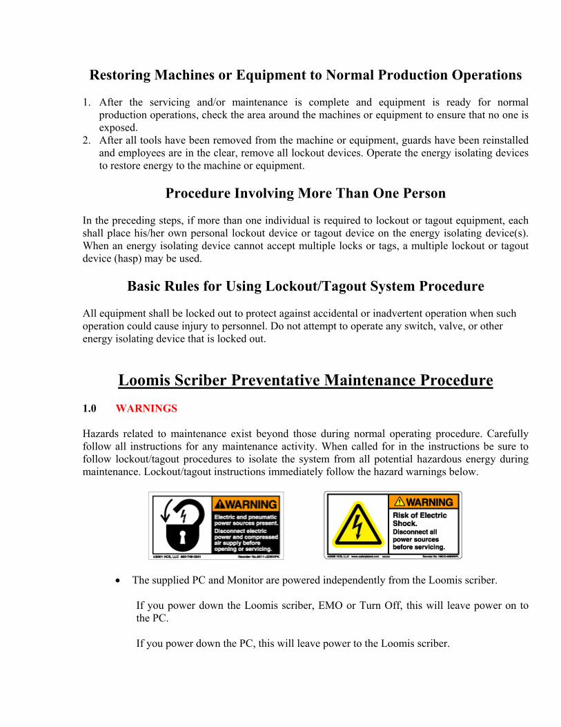
Loomis Scriber Preventative Maintenance Procedure 1.0 WARNINGS Hazards related to maintenance exist beyond those during normal operating procedure. Carefully follow all instructions for any maintenance activity. When called for in the instructions be sure to follow lockout/tagout procedures to isolate the system from all potential hazardous energy during maintenance. Lockout/tagout instructions immediately follow the hazard warnings below.
• The supplied PC and Monitor are powered independently from the Loomis scriber. If you power down the Loomis scriber, EMO or Turn Off, this will leave power on to the PC. If you power down the PC, this will leave power to the Loomis scriber.

• THE ELECTRICAL POWER TO THE LOOMIS SCRIBER IS TO BE TURNED
OFF AND LOCKED OUT WHEN WORKING ON THE MAIN ELECTRONICS BOARD OR SWITCHING POWER SUPPLIES.
2.0 SCOPE
This specification applies to the Loomis LSD-100 and 110 scribe and break systems. 3.0 OBJECTIVES
This document was designed to aid qualified technicians while performing Loomis scriber preventative maintenance. A moderate level of training and experience is required in order to properly utilize and implement the procedures contained in this document.
4.0 RESPONSIBILITY
It is the customer's responsibility to perform the preventative maintenance procedures as outlined within this document in order to maintain the Loomis Industries, Inc. product warranty.
5.0 APPLICABLE DOCUMENTATION
A. Loomis LSD-100 Complete Operations Manual. B. Loomis Technical Manual LSD-100 and 110.
6.0 REQUIREMENTS
7.1 The technician/engineer must be familiar with basic Loomis scriber set-up and operation procedures.
7.2 Provide and keep preventative maintenance records in a log. 7.0 SAFETY
The Loomis scriber uses HAZARDOUS VOLTAGE (115 VAC) to supply power to switching power supplies. All other circuitry is LOW VOLTAGE (12 and 24 VDC). Power should be DISCONNECTED and locked out when any of the protective covers or interlocks have been removed for preventative maintenance or service.

Series Preventative Maintenance Schedule
FREQUENCY
DESCRIPTION
EST. TIME REQUIRED
DAILY
Check tool angle
5 minutes
Check tool mileage report, service scribe tool if necessary
5 minutes
WEEKLY
Check Gases supply (CDA or nitrogen, vacuum)
2 minutes
Wipe Down Entire Machine including Covers, Mechanism Area, etc.
10 minutes
Wipe Down Y-axis V-Ways, lubricate with synthetic vacuum pump oil.
10 minutes
6 MONTHS
Check X-axis leadscrew for signs of wear and need for Replacement. Clean and lubricate with vacuum pump oil as necessary.
15 minutes
Disposal of Solid Waste As a result of operation, maintenance and servicing of the Loomis scriber, some items become solid waste. Disposal of these items might be regulated; therefore these items need to be disposed of properly. These items include:
• Contaminated wafer holding film
• Swabs used for cleaning
• Lithium batteries from the PC
• Wipe cloths used for maintenance
• Computer monitors containing lead or mercury
Local and regional regulations governing disposal of hazardous materials vary. The customer knows what chemistries are used in the system and is therefore responsible for knowing and following applicable local, state or provincial and national regulations regarding disposal.
Decontamination and Decommissioning

Purpose This chapter defines the requirements for handling used equipment or components that have been exposed to hazardous materials. The purpose of these procedures is to minimize or eliminate:
• Potential exposure to hazardous materials by personnel who are required to handle, modify, retrofit, refurbish, or recondition used equipment and parts,
• Potential environmental liability when authorizing receipt of hazardous materials on site,
• The unintentional release of hazardous waste.
Terminology
Decontamination is the removal of risks or hazards to human health or the environment that result from the presence of hazardous materials in or on equipment.
Equipment refers to process tools, chemical (liquid or gas) controls and delivery systems, ancillary support systems, structures, piping, ductwork, parts, and subassemblies (e.g., vacuum pumps, pump packages, effluent/exhaust treatment systems), purchased from SVG.
Free liquids are those that can be poured or drained from equipment when the equipment is held in any orientation. Loomis equipment uses NO liquids.
Hazardous material is any chemical, substance, or compound that is defined or interpreted as posing risks or hazards to human health or the environment according to international, federal, state, or local laws or regulations.
Health hazard is defined as a chemical for which there is statistically significant evidence based on at least one study, conducted in accordance with established scientific principles, that acute or chronic health effects may occur in exposed persons. Health hazards include chemicals that are carcinogens, toxic materials, reproductive toxins, irritants, corrosives, sensitizers, hepatotoxins, neurotoxins, agents that act on the hematopoietic system, and agents that damage the lungs, skin eyes or mucous membranes.
Physical hazard is defined as a chemical for which there is scientifically valid evidence that it is a combustible liquid, compressed gas, cryogenic, explosive, flammable gas, flammable liquid, flammable solid, organic peroxide, oxidizer, pyrophoric, unstable (reactive), or water-reactive material.
Transferor is the party with physical custody of the equipment and responsibility for transfer.
Transferee is the party who will receive physical custody of the equipment.

Decommissioning If the need to decommission arises, disassemble all parts and dispose of them as scrap or recyclable materials, according to on-site procedures. The largest percentage of material in the system is metal (aluminum). The wiring can be scrapped and the PCBs can be stripped of the copper. The PC and monitor, if unusable, can be recycled. Check local listings for electronics recycling facilities.
Scope and Responsibility These procedures describe minimum requirements for documentation of decontamination, and notification of residual hazards associated with decontamination. Their intent is to make certain that decontamination is completed to the utmost extent prior to transport or disposal of the equipment. They further address decontamination steps required to prepare equipment for end-of-life disposal. It is the responsibility of those transferring the equipment to ensure removal or minimization of all hazardous materials prior to transfer, relocation, or disposal. Hazards may exist that are not addressed in the procedures. In some cases, complete chemical decontamination cannot be achieved without destruction of the equipment. The person or persons transferring the equipment should make sure that any remaining potential hazards are clearly identified. It is the responsibility of those transferring the equipment residues, waste materials, and scrap parts generated as part of the decontamination process or end-of-life disposal to do so according to local, state, federal, and international regulations. If you are uncertain about equipment, contact the on-site EHS officer.
Applicable Documents
• SEMI S12-0298, Guidelines for Equipment Decontamination
Procedures
Personnel Safety Only properly trained and equipped personnel should perform assessment and decontamination procedures. To ensure compliance with applicable law, all specific procedures utilized to follow these guidelines should be pre-approved by the site Environmental, Health and Safety organization prior to decontamination activities. Use of appropriate personal protective equipment (PPE) should be addressed for each decontamination activity.

Equipment Assessment Prior to Decontamination Assessment of equipment should initially consider history of the equipment and visual inspection. If initial assessment shows a potential for equipment to have contacted hazardous materials during the life of the equipment, further assessment needs to be performed. Decontamination analysis should be performed on all areas of equipment that had potentially contacted hazardous materials during the life of the equipment, unless the areas are determined to be non-hazardous by the criteria set forth in this section. These areas include external surfaces, internal areas that are accessible without disassembly, and areas accessible during normal operations. Normally inaccessible areas should be addressed on a case-by-case basis by the site Environmental, Health and Safety organization. Removable parts may also require cleaning. A visible residue on equipment surfaces, including liquids, powders, flakes, or films, may indicate the presence of hazardous materials. All residues should be assumed to be hazardous unless otherwise determined and documented by appropriate test, analysis, or evaluation. Wipe sampling and chemical testing verifying the absence of physical and health hazards is recommended for all equipment that has been exposed to hazardous materials (regardless of the presence of visible residues). Refer to SEMI S12 or consult the on-site EHS person for wipe sampling procedures. If assessment results indicate that the equipment should be decontaminated prior to transfer, see Requirements for Decontamination. If assessment indicates that the equipment requires decontamination but will not or cannot be decontaminated prior to transfer, see Requirements for Equipment Transfers without Complete Decontamination.
Requirements for Decontamination Prior to decontamination, the equipment should be evaluated for abnormalities or non-functionality that may affect the evaluation and decontamination efforts. Equipment should be decontaminated before movement. If movement of the equipment is required prior to decontamination, precautions should be taken to remove all potential sources of leakage, spillage, off-gassing or hazardous material emissions through draining, purging and then use appropriate barriers, covers or containment devices. All applicable lockout/tagout procedures must be followed. Equipment parts that are routinely removed from the equipment for cleaning, should be cleaned prior to equipment transfer. Parts that are removed but not replaced should be disposed of per local regulations. All gas lines on the equipment should be appropriately purged, and secured with blanking plugs, caps or similar devices designed to remain in the equipment during handling and transport.

Thorough decontamination may not be achieved within component systems or equipment due to inaccessibility (i.e. "dead zone") or to physical characteristics of materials. Equipment with such zones require additional cycle purges and/or disassembly for access and proper cleaning. If complete decontamination cannot be achieved, follow Requirements for Equipment Transfers without Complete Decontamination.
Requirements for Equipment Transfers without Complete Decontamination
In some cases complete decontamination cannot or will not be desired or achieved for various reasons (e.g. pumps). This section establishes guidelines for the transfer of equipment intended for further productive use, which cannot or will not be completely decontaminated prior to transfer.
• If the contaminated equipment is a sub-component or subassembly of a larger piece of equipment which will not be otherwise decontaminated, the contaminated sub-assembly or component should be removed and transferred separately as specified above.
• Prior to transfer, the transferor must ensure that any remaining potential hazards are clearly identified to persons handling, transporting, and receiving the equipment.
• Obtain prior approval from intended transferee before shipping the equipment.
• Transportation and transfer of contaminated equipment is the same as transportation of hazardous materials and the process must meet all applicable local, state, national, and international regulations and organization policies.

Necessary Tools Normal Operation The tools necessary to operate the Loomis LSD-100/110 include the following:
Part Number Description 2900-0002 39-17 Angle Template 2900-0005 17-43 Angle Template 5400-0008 Hex-wrench set, Standard American Plastic Shim Stock Tools that may be necessary for non-normal maintenance include: Digital Multimeter Air pressure gauge Vacuum gauge Hex-wrench set, Standard American Hex-wrench set, Metric Screw drivers, Standard and Philips Small adjustable wrench Dial indicator Indicator stand Lab-grade granite surface plate Vernier calipers Swabs Cleaning cloth These tools are not supplied by Loomis Industries, Inc.

3
General Safety Instructions
Pinch Point
• Punto di Pizzicatura • Quetschpunkt • Zone de Pincement
CAUTIONPinch point, keephands and fingers clear.
ATTENZIONEPunto di pizzicatura, tener lontane mani e dita.
ACHTUNGQuetschpunkt, Hände und Finger fernhalten.
ATTENTIONZone de pincement, garder les mains et les doigts à l'ècart.
English - The machine operator must take care to keep hands and fingers clear whenever the machine is initializing, traversing, or indexing.
Italiano - L’operatore del dispositivo deve fare attenzione a tenere le mani e le dita lontane dalle zone di pericolo quando il dispositivo inizializza, opera uno spostamento trasversale o di divisione.
Deutsch - Der Bediener sollte bei Anlauf, Durchlauf und Schalten der Maschine darauf achten, Hände und Finger fernzuhalten.
Français - L’utilisateur de la machine doit faire attention de garder les mains et les doigts à l’écart pendant les opérations de lancement, de déplacement et d’indexation.

4
Emergency Stop Switch
L’interruttore di arresto di emergenza • Notfall Schalter • L’interrupteur d’urgence
English -
The Emergency Stop Switch should be placed either to the left or right of the Scriber/Breaker, depending on whether the operator is left or right handed. The Emer-gency Stop Switch is activated by striking it in a downward motion using one’s hand. The Emergency Stop Switch will halt all motor activity thus stopping the machine. After the Switch has been activated, the software will prompt the operator to mouse click “OK” on the monitor screen. This will exit the Loomis program and bring you to the main Win-dows screen. Once you have returned to the Windows main screen, you can reset the Switch by turning the red knob on the Switch clockwise until it “pops” up into it’s original position. Once this has been done the Loomis software can then be restarted.
Italiano -
L’interruttore di arresto di emergenza deve essere posizionato o sulla destra o sulla sinistra dello Scriber/Breaker, basandosi sulla preferenza di utilizzo da parte dell’operatore, che potrebbe usare la mano destra o essere mancino. L’interruttore di arresto di emergenza serve ad arrestare tutte le attività del motore e a fermarne, quindi, il funzionamento. Una volta attivato tale interruttore, il software dà il prompt all’operatore di fare clic con il mouse sullo schermo del monitor. Con tale azione si esce dal pro-gramma Loomis e si ritorna all schermata principale di Windows. Una volta ritornati alla schermata principale di Windows, è possibile ripristinare l’interruttore girando la manop-ola rossa dell’interruttore in direzione orario fino a quando questa non “sarà scattata” nella sua posizione originale. A completamento di queste fasi si potrà riavviare il software Loo-mis.

5
Emergency Stop Switch
L’interruttore di arresto di emergenza • L’interrupteur d’urgence
Deutsch -
Abhängig davon, ob der Bediener Rechts-oder Linkshänder ist, sollte der Not-Aus-Schalter entweder links oder rechts vom Griffel/Brecher angebracht werden. Der Not-Aus-Schalter wird mit einer von der rechten oder linken Hand nach unten aus-gefûhrten Bewegung betätigt. Bei Betätigung des Not-Aus-Schalters wird jegliche Motor-tätigkeit eingestellt, die Maschine kommt zum Stillstand. Nachdem der Schalter betätigt wurde, wird der Bediener vom Software-Programm aufgefordert, mit der Maus im Bild-schirm auf “OK” zu klicken. Damit wird das Loomis-Programm beendet, und Sie befin-den sich wieder im Windows-Menû. Nachdem Sie zum Windows-Menû zurûckgekehrt sind, können Sie den Schalter wieder zurûcksetzen, indem Sie den roten Knopf am Schal-ter im Uhrzeigersinn drehen, bis er in Ausgangsposition zurûckspringt. Danach kann die Loomis-Software erneut gestartet werden.
Français -
Placer l’interrupteur d’urgence à gauche, ou à droite, du Traceur/Disjoncteur, en fonction de la dextérité, gauche ou droite, de l’utilisateur. Abaisser ou soulever l’inter-rupteur d’urgence, à la main, pour l’actionner. L’interrupteur d’urgence inactive moteur et de ce fait arrête la machine. Lorsque l’interrupteur d’urgence est actionné, le logiciel sig-nalera à l’utilisateur de sélectionner “OK”, affiché à l’écran. Cette action permet de quit-ter le logiciel Loomis pour retourner à l’affichage principal de Windows. De retour à l’affichage principal de Windows, vous pouvez remettre l’interrupteur à zéro en faisant tourner, dans le sens des aiguilles d’une montre, le bouton rouge de l’interrupteur jusqu’au déclic qui signale sa position initiale. Lorsque cette opération est terminée, le redémar-rage du logiciel Loomis peut s’effectuer.
6
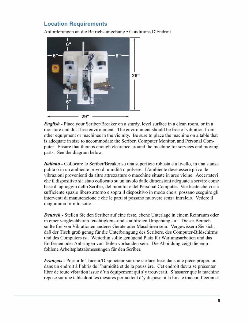
Location Requirements
Anforderungen an die Betriebsumgebung • Conditions D'Endroit
English -
Place your Scriber/Breaker on a sturdy, level surface in a clean room, or in a moisture and dust free environment. The environment should be free of vibration from other equipment or machines in the vicinity. Be sure to place the machine on a table that is adequate in size to accommodate the Scriber, Computer Monitor, and Personal Com-puter. Ensure that there is enough clearance around the machine for services and moving parts. See the diagram below.
Italiano -
Collocare lo Scriber/Breaker su una superficie robusta e a livello, in una stanza pulita o in un ambiente privo di umiditá o polvere. L’ambiente deve essere privo de vibrazioni provenienti da altre attrezzature o macchine situate in aree vicine. Accertatevi che il dispositivo sia stato collocato su un tavolo dalle dimensioni adeguate a servire come base di appoggio dello Scriber, del monitor e del Personal Computer. Verificate che vi sia sufficiente spazio libero attorno e sopra il dispositivo in modo che si possano eseguire gli interventi di manutenzione e che le parti si possano muovere senza intralcio. Vedere il diagramma fornito sotto.
Deutsch -
Stellen Sie den Scriber auf eine feste, ebene Unterlage in einem Reinraum oder in einer vergleichbaren feuchtigkeits-und staubfreien Umgebung auf. Dieser Bereich sollte frei von Vibrationen anderer Geräte oder Maschinen sein. Vergewissern Sie sich, daß der Tisch groß genug für die Unterbringung des Scribers, des Computer-Bildschirms und des Computers ist. Weiterhin sollte genügend Platz für Wartungsarbeiten und das Entfernen oder Anbringen von Teilen vorhanden sein. Die Abbildung zeigt die emp-fohlene Arbeitsplatzabmessungen für den Scriber.
Français -
Poseur le Traceur/Disjoncteur sur une surface lisse dans une pièce proper, ou dans un endroit à l’abris de l’humidité et de la poussière. Cet endroit devra se présenter libre de toute vibration issue d’un équipement qui s’y trouverait. S’assurer que la machine repose sur une table dont les mesures permettent d’y disposer à la fois le traceur, l’écran et
6" 8"
6"
6"
29"
26"

7
l’ordinateur. S’assurer qu’il existe suffisamment d’espace libre autour de la machine pour l’installation et les pièces amovibles. Se reporter au schéma ci-dessous.

8
LSD-100 Scribing and Breaking Principles
In this section we present an overview of wafer scribing and breaking with the LSD-100. The breaking process is integral with wafer scribing. The LSD-100 break mechanism consists of a break mandrel and a breakwheel. The break mandrel supports the wafer at the scribe line. Breaking occurs when the break wheel applies a bending force to the wafer along the scribe line. Proper alignment of the break mechanism to the scribing direction (Y) is essential for consistent die creation.
By the end of this section, you will understand:
•
How Scribing and Breaking is done on the LSD-100.
•
Factors that affect break quality
•
Implications of break foot misalignment

9
Process Page
Material Handling Requirements
Wafer Film 3200-0357, is mounted to Square Frame 7550-0081, using Frame Compressor7550-0068, to compress frame and mount the film. After the film and frame are assembled, they arereleased from the fixture. The wafer is then placed face down onto the fixture. The film / frame assembly are then placed adhesive side down against the backside of the wafer. The wafer film and the backside of the wafer are pressed together thus eliminating air entrapment between wafer and film.
Machine Sequence of Operation
Install Film/Frame/Wafer assembly on the LSD-100; Rotationally align wafer so that the scribe channel is parallel to the scribe motion. Locate the first scribe and break channel on the right side of the wafer, and verify the index dimension. Commence automatic Scribe and Break of wafer converting it into strips. Rotate Film/Frame/Wafer assembly 90 degrees, then repeat operations of Scribe and Break turning strips into die.
Equipment Performance requirements
The wafer will be scribed and broken 100% through.
The wafer must be aligned to frame within +/-2 degrees.
The wafer must be mounted to frame within +/-1mm.
The tension exerted by the frame on the film is approximately 1 Kg.
Dimensional Tolerance of Dice
Best yield are obtained when a ratio of 2 to 1 is used, meaning that the die size is at least twice the thicknessof the wafer material.
Yield
Controlled test 99%
Continuous operation 95-99%.

10
When scribing wafers with many die, it may be necessary to first Scribe onlyin the first direction , and then Scribe and Break in the second direction . Then after the second direction has been scribed and broken into strips, it is necessary to rotate 90 deg. again and Break only in the first direction completely breaking up the wafer into die.
The reason that we may have to do this type of procedure when scribing is that some-times when you Scribe and Break the wafer into strips in the first direction, and then rotate 90Deg. and try to align the wafer channel for scribing , the wafer channel may now have a “Bow”due to the movement of the strips on the Wafer Tape. So in order to eliminate the chance ofBowing , we must Scribe only in the first direction .
Depending on the application and material being scribed , it may or may not be neces-sary to use the above mentioned procedure. One should first try to Scribe and Break in both dir-ections and then determine if it is necessary . If it is necessary to use the above mentioned pro-cedure, we have determined that in most cases it is best to Scribe only in the first direction withthe small die dimension first. With Sapphire substrate, the large die dimension should be first.
First Direction: Scribe Only.
Second Direction: Scribe and Break.
Third Step: Return to first direction and Break Only.
Scribing Principles
�
F/2Reaction Pad
F
F/2
Roller
Two ProfileBreak Wheel
Wafer
Film
Mandrel
Roller Break 3-Point Bending+
Loomis Controlled Strain Breaking System
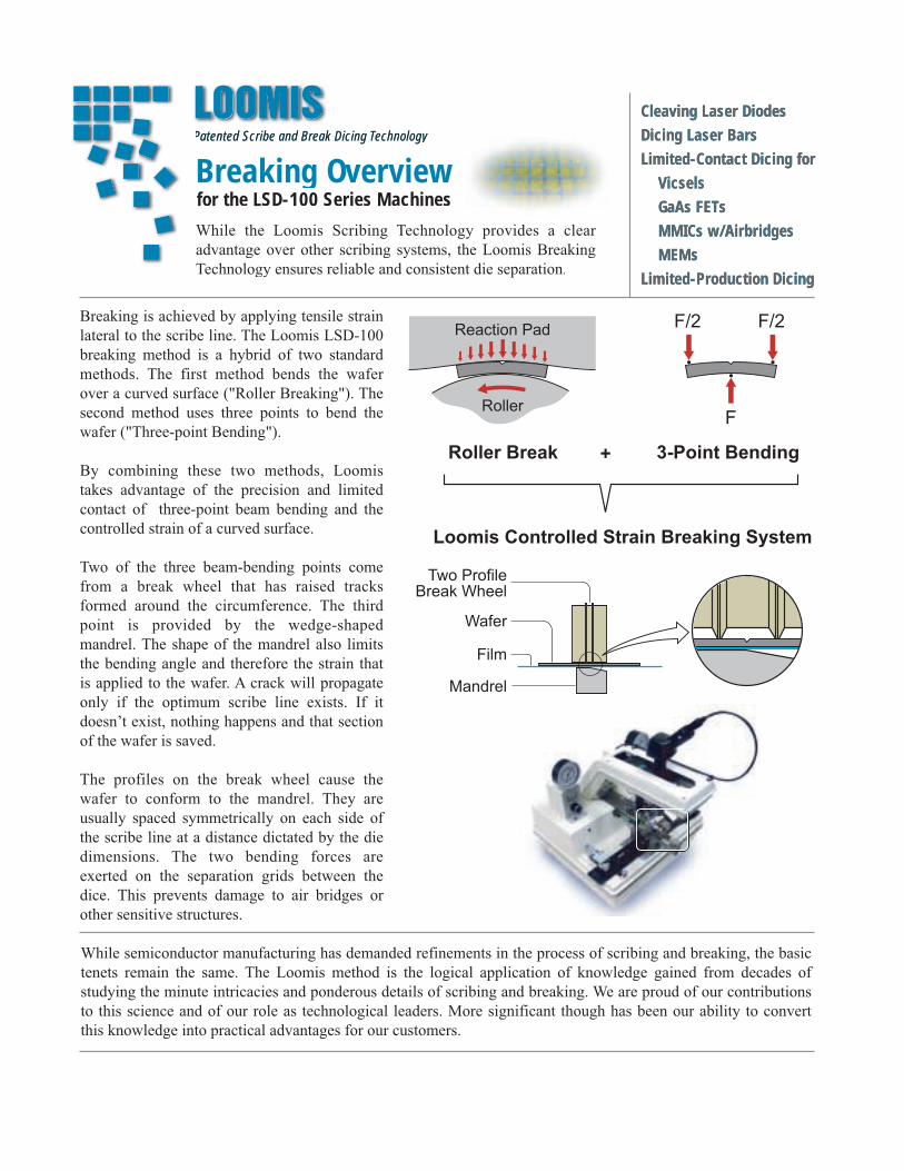
Breaking Overviewfor the LSD-100 Series Machines
Patented Scribe and Break Dicing TechnologyPatented Scribe and Break Dicing Technology
Breaking is achieved by applying tensile strain
lateral to the scribe line. The Loomis LSD-100
breaking method is a hybrid of two standard
methods. The first method bends the wafer
over a curved surface ("Roller Breaking"). The
second method uses three points to bend the
wafer ("Three-point Bending").
By combining these two methods, Loomis
takes advantage of the precision and limited
contact of three-point beam bending and the
controlled strain of a curved surface.
Two of the three beam-bending points come
from a break wheel that has raised tracks
formed around the circumference. The third
point is provided by the wedge-shaped
mandrel. The shape of the mandrel also limits
the bending angle and therefore the strain that
is applied to the wafer. A crack will propagate
only if the optimum scribe line exists. If it
doesn’t exist, nothing happens and that section
of the wafer is saved.
The profiles on the break wheel cause the
wafer to conform to the mandrel. They are
usually spaced symmetrically on each side of
the scribe line at a distance dictated by the die
dimensions. The two bending forces are
exerted on the separation grids between the
dice. This prevents damage to air bridges or
other sensitive structures.
While the Loomis Scribing Technology provides a clear
advantage over other scribing systems, the Loomis Breaking
Technology ensures reliable and consistent die separation.
While semiconductor manufacturing has demanded refinements in the process of scribing and breaking, the basic
tenets remain the same. The Loomis method is the logical application of knowledge gained from decades of
studying the minute intricacies and ponderous details of scribing and breaking. We are proud of our contributions
to this science and of our role as technological leaders. More significant though has been our ability to convert
this knowledge into practical advantages for our customers.
Cleaving Laser DiodesDicing Laser BarsLimited-Contact Dicing for Vicsels GaAs FETs MMICs w/Airbridges MEMsLimited-Production Dicing
Cleaving Laser DiodesDicing Laser BarsLimited-Contact Dicing for Vicsels GaAs FETs MMICs w/Airbridges MEMsLimited-Production Dicing

12
Wafer Orientation and Avoiding Excessive Scribing Distortion
Summary
Loomis dicing machines use an expansion film to separate individual dice and bars as they are scribed and broken. This method is advantageous for eliminating contact and chipping between adjacent dice and bars. However, the expansion film introduces additional con-siderations during the dicing process. When scribing and breaking a round wafer in the secondary direction, distortion can occur. Problems associated with distortion can be avoided using proper wafer orientation and/or intermittent breaking as described below.
Wafer Orientation During Scribing and Breaking
Two methods are depicted for orienting and scribing the wafer. Method 1 is faster but may cause distortion of when scribing and breaking in the secondary direction.
largerindex
smaller index
Method 1
Method 2
Step 1: Scribe and break in the smaller index direction.
Step 2: Scribe and break in the larger index direction.
Step 1: Scribe only (do not break) in the larger index direction
Step 2: Scribe and break in the smaller index direction.
Step 3: Break only in the larger index direction.
SB SB
S SB B

13
Scribing Distortion (“Bow”)
The illustration below depicts misalignment problems that could occur when using Method 1 when scribing and breaking a wafer in the secondary direction. This is due to the necessary expansion of the Wafer Adhesive Film.
If the amount of distortion is acceptable, then Method 1 provides the fastest way to scribe the wafer. If excessive distortions exists, Method 2 is recommended.
Another approach to avoid excessive distortion when scribing and breaking in the second-
ary direction, is to initially scribe and break every separation channel, where
n
is defined by the following equation:
r
is the wafer radius,
c
is the width of the die,
d
is the amount of expansion of the film on
one side
of the break, and
t
is the allowable curvature tolerance (nominally 1/5 to 1/4 of a separation channel width), and ceiling is the mathematical operator that rounds up to the nearest integer.
As an example, assume that we are scribing a 50 mm wafer with die dimension of 375
µ
m and 50
µ
m separation channels. Also, from previous experience we know that the expan-sion drift creates a 1
µ
m separation between dice.
From this calculation, we should scribe and break every 7th separation channel.
Note: Dimensions exaggerated for illustrative purposes.
nth
n ceilingrc-- d
t---⋅
=
n ceiling25mm
0.375mm---------------------- 0.0005mm
0.005mm-------------------------⋅
ceiling 6.667( ) 7= = =

Vacuum
Computer
Monitor
LSD Machine
Video
Converter
Pressure
Emergency
Stop
Power
Connections

15
Machine Components
By the end of this section, you will be able to:
•
Locate and Identify various machine parts.
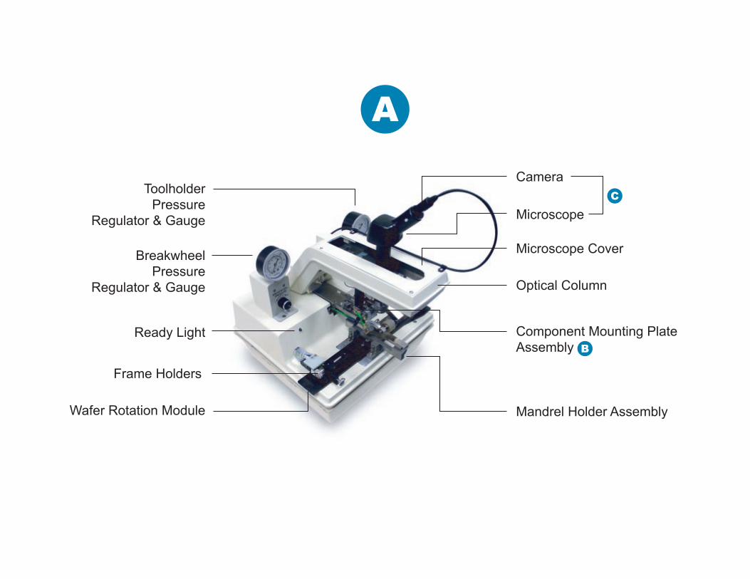
Toolholder
Pressure
Regulator & Gauge
Breakwheel
Pressure
Regulator & Gauge
Ready Light
Frame Holders
Wafer Rotation Module Mandrel Holder Assembly
Component Mounting Plate
Assembly
Microscope Cover
Optical Column
Microscope
Camera
A
B
C
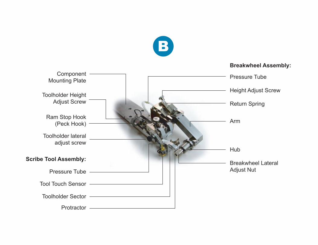
B
Component
Mounting Plate
Ram Stop Hook
(Peck Hook)
Toolholder lateral
adjust screw
Toolholder Height
Adjust Screw
Scribe Tool Assembly:
Protractor
Toolholder Sector
Tool Touch Sensor
Pressure Tube
Breakwheel Lateral
Adjust Nut
Arm
Hub
Return Spring
Height Adjust Screw
Pressure Tube
Breakwheel Assembly:
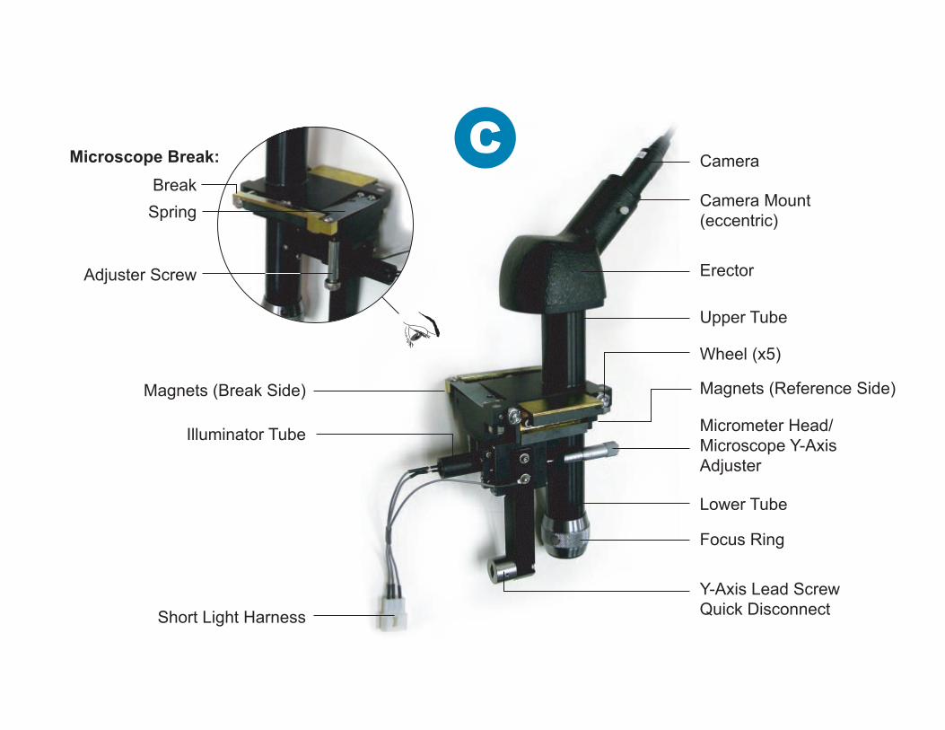
CMicroscope Break:
Illuminator Tube
Spring
Break
Adjuster Screw
Magnets (Break Side) Magnets (Reference Side)
Short Light Harness
Lower Tube
Focus Ring
Y-Axis Lead Screw
Quick Disconnect
Wheel (x5)
Micrometer Head/
Microscope Y-Axis
Adjuster
Upper Tube
Erector
Camera Mount
(eccentric)
Camera

19
Getting Started - Powering Up
By the end of this section, you will know how to:
•
Power up LSD system.
•
Invoke the LSD-7xx control software.

20
Power-up Procedure
To power-up the hardware systems, follow these steps in order:
1
Make sure that all components are turned off.
2
Turn on the monitor, Video Camera Box, and then the computer.
3
After the computer has booted up, turn on LSD machine. The LSD will go through a series of tests indicated by a slowly flashing green light. When the tests are complete, The green Light will flash more rapidly.
To start up the LSD software:
1
Double-click on the LSD-7xx software icon located on the Windows desktop. The software will perform a series of tests and configuration steps.
During the series of tests, a warning will appear instructing the user to keep their hands clear, because the X-slide is about to initialize.. The X-slide and mandrel mount can pinch fingers and hands (see “General Safety” instructions). Clear hands from the area, and then click on “OK” in the dialog box to continue.

21
Wafer and Film Mounting
By the end of this section, you will know how to:
•
Mount Wafer Holding Film onto the Square Expansion Frame
•
Mount a wafer to the holding film
To perform the tasks, you will need the following materials:
•
Double-sided adhesive tape (dispenser and tape are Loomis issue)
•
Frame Contractor
•
Square Expansion Frame
•
Wafer protective paper
•
Cotton swabs or sponge
22
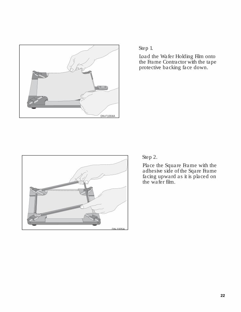
Step 1.Load the Wafer Holding Film ontothe Frame Contractor with the tapeprotective backing face down.
DN-F1004A
DN-1005A
Step 2.Place the Square Frame with theadhesive side of the Sqare Framefacing upward as it is placed onthe wafer film.

23
DN-F1006A
Step 3.
Compress the Square Frameby pulling the CompressorHandle toward the front until itlocks into place.
DN-F5007A
Step 4.
Using your thumb and forefinger,wrap the Wafer holding Filmaround the outer surface of theSquare Frame pressing the filmagainst the adhesive on the FrameRail.

24
Step 5
Remove the Square Frame/wafer Holding Film assembly off of theFrame Contractor.
Step 6
Peel off the paper or plastic protectivebacking material.
Step 7
Place a sheet of wafer protective paperdown in the center of the Frame Compressor.
DN-F5008A
DN-F5009A
DN-F5010A

25
Step 8.
Place the wafer to be scribed facedown on to the protective paper,with the wafer flat parallel to one ofthe sides of the Frame Compressor.
DN-F5012A
Step 9.
Place the Wafer Holding Frame assemblywith the adhesive side of the tape facingdown, or against the wafer.
Step 10.
Attach the wafer to the film by gentlyrubbing the back of the Wafer holding filmwith a cotton swab pressing it on tothe wafer. Ensure that all of the airbubbles are not present between thewafer and the wafer holding film..
DN-F5013A
DN-F5011A
26
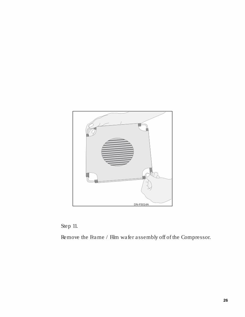
DN-F5014A
Step 11.
Remove the Frame / Film wafer assembly off of the Compressor.

27
DN-F5015A

28
Mounting and Aligning Wafer Frame
Before mounting and aligning the Wafer Frame:
•
Mount the Wafer Holding film to the Square Frame, and then mount a wafer to the Film frame Assembly.
By the end of this section, you will know how to:
•
Mount the Square Expansion Frame to an LSD Dicing Machine
•
Align the wafer to microscope travel and therefore to the Scribing Direction (Y)
To perform the tasks, you will need the following materials:
•
A Wafer-Film-Frame Assembly (see “Wafer Mounting” instructions)
29
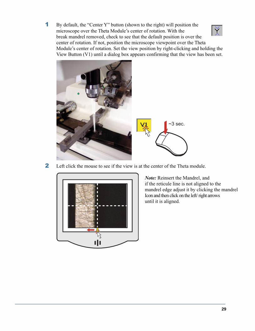
1
By default, the “Center Y” button (shown to the right) will position the microscope over the Theta Module’s center of rotation. With the break mandrel removed, check to see that the default position is over the center of rotation. If not, position the microscope viewpoint over the ThetaModule’s center of rotation. Set the view position by right-clicking and holding the View Button (V1) until a dialog box appears confirming that the view has been set.
2
Left click the mouse to see if the view is at the center of the Theta module.
~3 sec.
Note: Reinsert the Mandrel, and if the reticule line is not aligned to the mandrel edge adjust it by clicking the mandrel Icon and then click on the left/ right arrows until it is aligned.
30
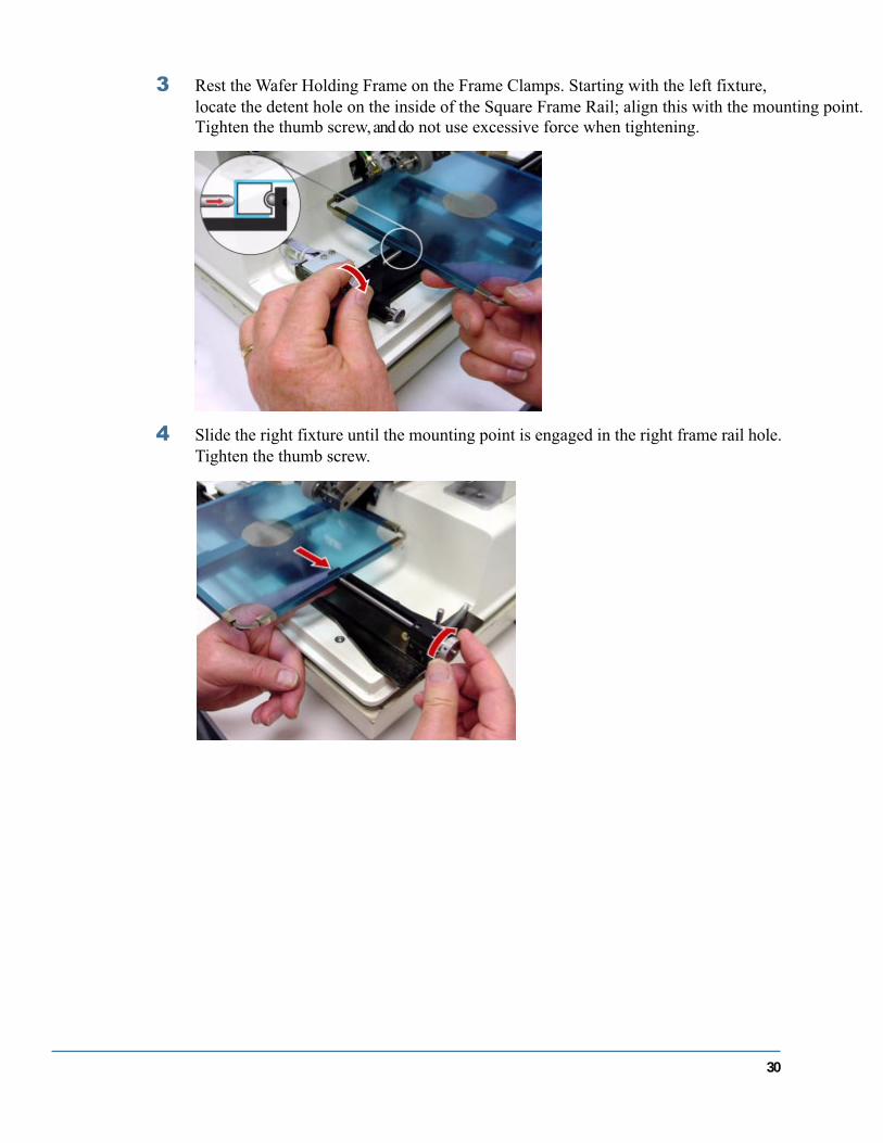
3
Rest the Wafer Holding Frame on the Frame Clamps. Starting with the left fixture, locate the detent hole on the inside of the Square Frame Rail; align this with the mounting point. Tighten the thumb screw, and do not use excessive force when tightening.
4
Slide the right fixture until the mounting point is engaged in the right frame rail hole. Tighten the thumb screw.
31
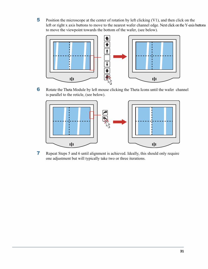
5
Position the microscope at the center of rotation by left clicking (V1), and then click on the left or right x axis buttons to move to the nearest wafer channel edge. Next click on the Y-axis buttons to move the viewpoint towards the bottom of the wafer, (see below).
6
Rotate the Theta Module by left mouse clicking the Theta Icons until the wafer channelis parallel to the reticle, (see below).
7
Repeat Steps 5 and 6 until alignment is achieved. Ideally, this should only require one adjustment but will typically take two or three iterations.

32
Scribe Tool Installation and Replacement
Before starting:
•
Select the proper Scribe Tool (refer to
“Scribe Tool-Material Chart”
)
•
Align the reticle to the Break Mandrel Edge
By the end of this section, you will know how to:
•
Consistently install and replace a Scribe Tool
•
Adjust the height and angle of the Scribe Tool
•
Laterally adjust the Scribe Tool to the reticle.
Summary
Scribing is the central activity of the Loomis machine. To create an effective scribe line, the Scribe Tool must be positioned with care. For scribing, the height of the Scribe Tool must be set properly so that it does not adversely affect scribing angle. For pecking, the height of the Scribe Tool affects the length of a peck. The angle of the Scribe Tool deter-mines the corner of the faceted scribe point that contacts the wafer. Different combinations of Scribe Tool models and wafer material require different angles (refer to the “Scribe Tool-Material Chart” for details).The height and angle of the Scribe Tool are adjusted independently but are coupled. That is, changing the height also changes the scribe angle and vice versa. Therefore, achieving the proper combination of height and angle requires iteration.

33
Scribe Tool Installation
To install a scribe tool:
1
Partially insert the Scribe Tool (point facing down) into Scribe Tool Holder (“Wind-mill”). In most cases the Scribe Tool can be positioned so that a “T” is visible from the front or from the side. The “T”
should not
be engaged with the Windmill.
2
Lightly secure the nylon screw against the Scribe Tool Shank. This ensures that the shank is aligned along the long axis of the scribe tool.
3
Insert the Scribe Tool completely into the Windmill and firmly tighten the nylon screw.
Lightly
Firmly
34
Scribe Tool Adjustment
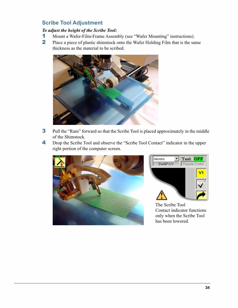
To adjust the height of the Scribe Tool:
1
Mount a Wafer-Film-Frame Assembly (see “Wafer Mounting” instructions).
2
Place a piece of plastic shimstock onto the Wafer Holding Film that is the same thickness as the material to be scribed.
3
Pull the “Ram” forward so that the Scribe Tool is placed approximately in the middle of the Shimstock.
4
Drop the Scribe Tool and observe the “Scribe Tool Contact” indicator in the upper right portion of the computer screen.
The Scribe Tool Contact indicator functions only when the Scribe Tool has been lowered.
35
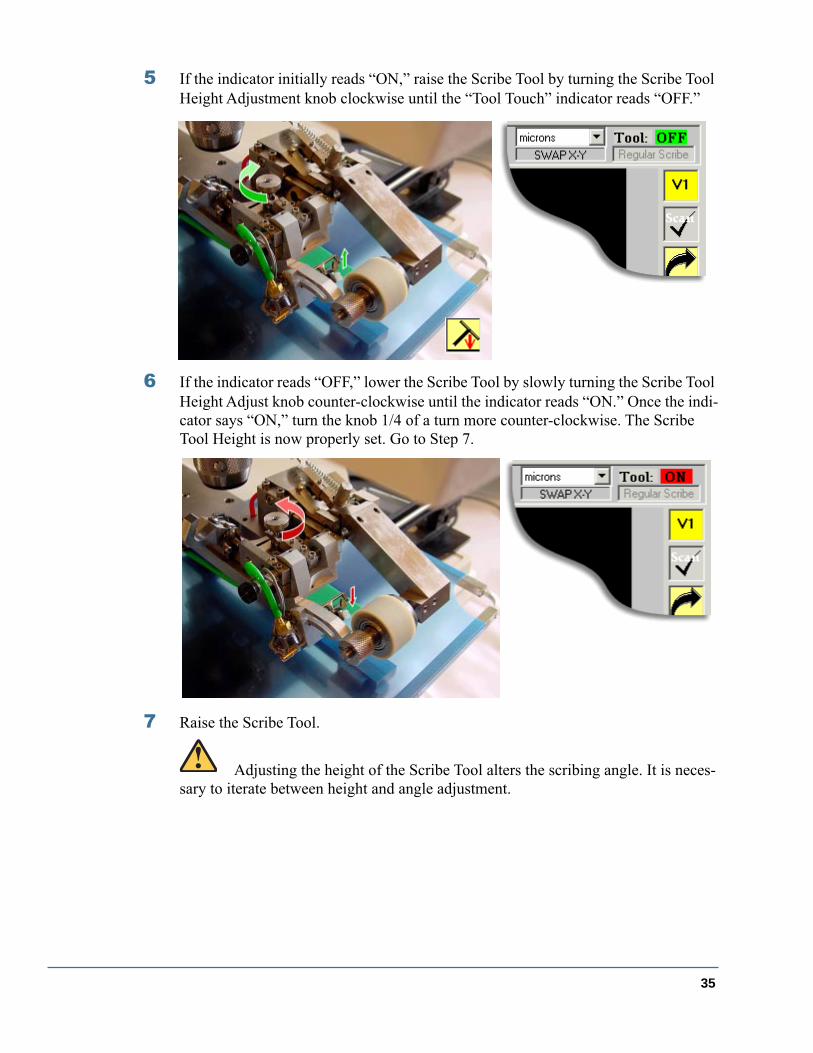
5
If the indicator initially reads “ON,” raise the Scribe Tool by turning the Scribe Tool Height Adjustment knob clockwise until the “Tool Touch” indicator reads “OFF.”
6
If the indicator reads “OFF,” lower the Scribe Tool by slowly turning the Scribe Tool Height Adjust knob counter-clockwise until the indicator reads “ON.” Once the indi-cator says “ON,” turn the knob 1/4 of a turn more counter-clockwise. The Scribe Tool Height is now properly set. Go to Step 7.
7
Raise the Scribe Tool.
Adjusting the height of the Scribe Tool alters the scribing angle. It is neces-sary to iterate between height and angle adjustment.
36
To adjust the angle of the Scribe Tool:
1
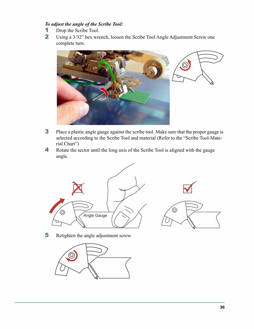
Drop the Scribe Tool.
2
Using a 3/32” hex wrench, loosen the Scribe Tool Angle Adjustment Screw one complete turn.
3
Place a plastic angle gauge against the scribe tool. Make sure that the proper gauge is selected according to the Scribe Tool and material (Refer to the “Scribe Tool-Mate-rial Chart”)
4
Rotate the sector until the long axis of the Scribe Tool is aligned with the gauge angle.
5
Retighten the angle adjustment screw.
Angle Gauge

37
To laterally adjust the Scribe Tool to the reticle:
1
Position the plastic shimstock in the path of the Scribe Tool.
2
Create a scribe line in the shimstock.
It may be helpful to move the shimstock in the X-direction to a region with no scribe lines.
Scr
ibe
Line

38
3
If the scribe line is not aligned with the reticle, translate the Scribe Tool by turning the Lateral Adjust Knob.
4
Repeat Steps 2 and 3 until the scribe line and the reticle are aligned.
One complete turn of the Lat-eral Adjust Knob will move the Scribe Tool approxi-mately 500 microns.
Scr
ibe
Line

39
Break Wheel Installation and Adjustment
Before starting, you should be familiar with:
•
Selecting a proper
Break Wheel according to the die size (see Break Wheel Specifica-tion sheet)
•
Aligning the reticule to the mandrel
•
Aligning the scribe line to the reticule
By the end of this section, you will know how to:
•
Install a Break Wheel
•
Laterally adjust the Break Wheel so that the Break Wheel Profiles are centered about the scribe line.
•
Adjust the height of the Break Wheel to the surface of the wafer or Wafer Holding Film.
To perform the tasks, you will need:
•
Felt tipped marker (Dry erase type)
•
Plastic shimstock
•
Wafer-Frame-Film Assembly
Summary
To ensure proper breaking, the profiles of the Breakwheel must be centered about the scribe line. We assume here that the scribe line has been aligned to the Break Mandrel edge.

40
Break Wheel Installation
To remove a Break Wheel:
1
Raise the Break Arm so that the Break Wheel is clearly above the protractor by loos-ening the Break Arm quick release screw.
2
The Break Wheel is held in place by magnets. Slide the wheel from the spindle to the left. Notice the engraved model number is facing left.
To mount a Break Wheel:
1
Raise the Break Arm so that the Break Wheel is clearly above the protractor by loos-ening the Break Arm quick release screw.
2
Slide the Break Wheel to the right ensuring that the engraved model number is fac-ing to the left and the taper to the right.
3
Ensure that the Breakwheel is completely seated against the magnetic spindle flange.
4
Retighten the quick release screw.
41
Break Wheel Adjustment
To adjust the height of the Break Wheel:
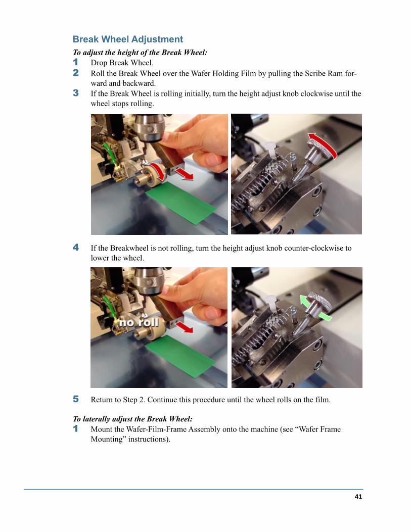
1
Drop Break Wheel.
2
Roll the Break Wheel over the Wafer Holding Film by pulling the Scribe Ram for-ward and backward.
3
If the Break Wheel is rolling initially, turn the height adjust knob clockwise until the wheel stops rolling.
4
If the Breakwheel is not rolling, turn the height adjust knob counter-clockwise to lower the wheel.
5
Return to Step 2. Continue this procedure until the wheel rolls on the film.
To laterally adjust the Break Wheel:
1
Mount the Wafer-Film-Frame Assembly onto the machine (see “Wafer Frame Mounting” instructions).
42
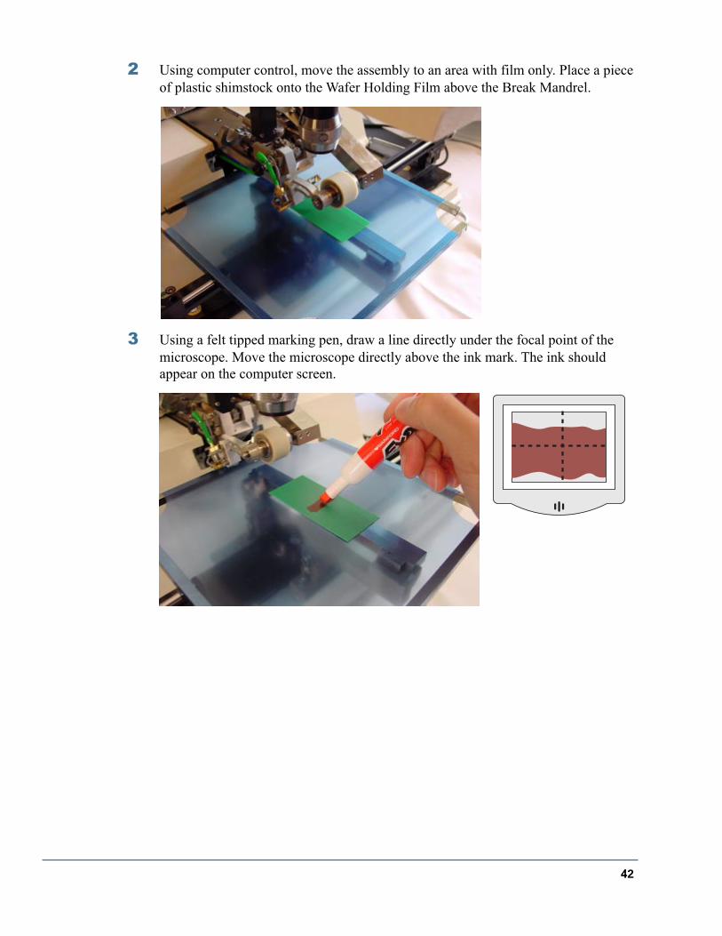
2
Using computer control, move the assembly to an area with film only. Place a piece of plastic shimstock onto the Wafer Holding Film above the Break Mandrel.
3
Using a felt tipped marking pen, draw a line directly under the focal point of the microscope. Move the microscope directly above the ink mark. The ink should appear on the computer screen.
43
4
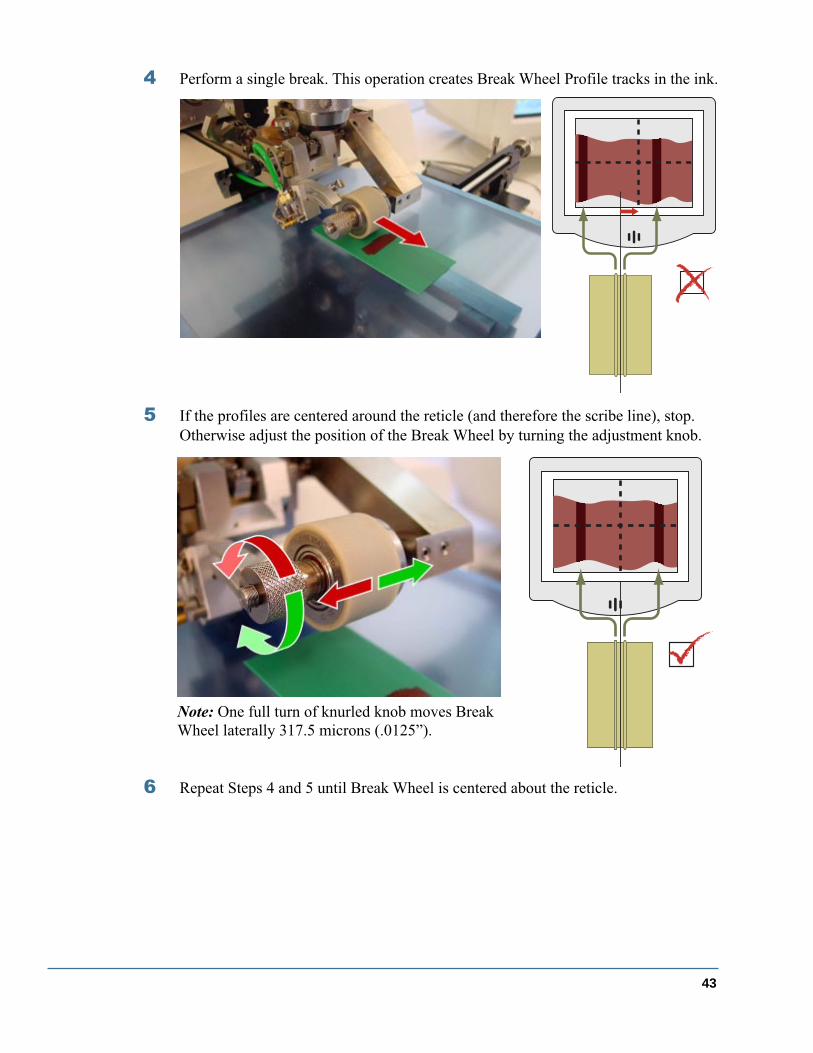
Perform a single break. This operation creates Break Wheel Profile tracks in the ink.
5
If the profiles are centered around the reticle (and therefore the scribe line), stop. Otherwise adjust the position of the Break Wheel by turning the adjustment knob.
6
Repeat Steps 4 and 5 until Break Wheel is centered about the reticle.
Note: One full turn of knurled knob moves Break Wheel laterally 317.5 microns (.0125”).

44
LSD-100 Software

45
Tool Drop Icon
Break Bar Drop Icon
Scribe Once Icon
Break Once Icon
Scribe and Break Once Icon
Center X Axis to nearest Channel
Measure X Icon
Measure Y Icon
Quick Traverse Buttons
Microscope Viewpoint Button
Scan Y-axis button
Theta Adjust buttons
Microscope Illuminator adjuster
Y-axis Microscope Index Button
Y-axis MicroscopeTraverse Buttons
Fast Medium Slow
Center Y-axis Microscope
Y-axis Microscope Traverse Buttons
Slow Medium fast
Y-axis Microscope Index Button
X-Axis Index Left Button
X-Axis Traverse Buttons Left
Fast Medium
Slow
X-Axis Traverse Buttons Right
Slow Medium
fast
X-Axis Index Right Button
Channel Center Button
Micro Step ButtonsStart Auto Scribe Button
Stop Everything Button
Wafer Direction ButtonReticule Setup ButtonVision System ButtonField Wafer Setup ButtonWafer Setup and Info PageConfiguration ButtonFile Cabinet Button
Scribe Mode Selection Box
Y-Axis Index Value BoxX-Axis Index Value BoxUnit Selection BoxTool Touch Indicator Box
LSD-100 Software Main Page

46
File Cabinet Page
This page displays the current LSD-100 software version and the current EPROM version used by the LSD-100 scribing machine control board.
Also, this is the place to come to for access to the master help system, making video images, and saving/restoring wafer setups.
Help! ButtonThis button gains access to the main help file table of contents.
Save Settings ButtonThis button will save ALL of the current LSD-100 settings to a file of the user's choice. Unless the operator invents a new name, the file name is the wafer name entered on the wafer setup page. The default folder is C:\LSD\LSDUSER\SETUPS. Make sure that the file name DOESN'T include any "\" or "/" characters, as this may cause the wafer setup file to be stored in an unexpected location. The machine setup, vision alignment, and tool odometer settings are stored in separate files.
Load Settings ButtonThis button will load a previously - saved setup from disk. Again, the default folder to search is C:\LSD\LSDUSER\SETUPS.
Restore Defaults ButtonThis button is similar to the LOAD SETTINGS button, but it will automatically load a file called DEFAULT.STP from the LSDEXE folder. Use this button to restore the default wafer setup for the LSD-100.
Video Image ButtonThis button jump to the video image page. From this page, still video images may be stored and retrieved from the system disk.
Exit ButtonThis button closes down the LSD-100 system and gives the user a choice of exiting back to Windows, Shutting Down the whole machine, or canceling the operation. For the first two choices, all the LSD-100 settings are saved to a file called "Previous.STP", it is this file that is loaded when the LSD-100 program starts.

47
Configuration Page
This page is where the most-commonly used scriber options are set. Come to this page to set the wafer size, change tool points, check the tool-odometer reading, set scribe-mode options, etc.
Wafer SizingSizeSelect the nominal size of the wafer being scribed here. This affects the YScan limit points and sets up the calculations for the tool odometer.
Wafer Is SquareChecking this box will inform the LSD system that the wafer is square, not round. This affects the end-point positions of the Y-Scan feature and tool odometer calculations.
YScan Over WheelThis forces the YScan feature to scan rearward all the way over the breakwheel to the rearmost limit.
Force YScanThis causes a YScan cycle of the microscope to occur after every scribe cycle. It is used primarily for testing a wafer / tool setup.
MicroIndexSelect the desired MicroIndex resolution. This is the index distance that will be performed when the operator hits the x-axis left or right micro index buttons <these buttons are located on either side of the Channel Center button>. This selection also sets the resolution of the X and Y axis index distance scroll button.
System Operation2nd Dir Break Every XX CyclesThis enables and sets how many cycles are performed before a break cycle occurs when the machine is in "second direction break" mode. When the check box is unchecked, the LSD is in normal break mode, and scribing and breaking occur on every cycle ( if the machine is in an automatic mode that supports scribing and breaking). When the box is checked, the machine can go into the "Second Direction Break Mode" when the user hits the Scribe Style Button on the main page. In the Second Direction Break mode, the machine will do XX number of scribe cycles before a scribe AND break cycle is executed. Normally the XX value is automatically set for a 10mm distance as calculated by the current X axis index distance, but can be set to any number by the operator.
Stop on "No Tool Touch"Selecting this option will cause the machine to automatically stop when the tool touch sensor ISN'T activated during a scribe cycle. This feature can stay turned off for most processes, but by all means try using it. The reliability of this feature goes down for thin or very narrow workpieces, like laser diode strips.
Vision Center Every XX CyclesNormally, the machine will perform a vision centering operation for every scribe cycle when the machine has the vision system activated. By checking this box and selecting a value for XX, the machine will perform a centering operation every XX scribe cycles. This is used to minimize the wafer scribe and break time.

48
Multi-Scribe Stroke per Cycle Checking this box and selecting a number of cycles will cause multiple
scribe / peck strokes to occur per cycle. This is normally used on wafers coated with thick metalization. Multiple scribe strokes will allow the scribe tool to "dig down" through the coatings and get a crack started in the substrate itself.
Multi-Break Strokes per CycleSimilar to above, this sets the number of break strokes per cycle.
Adjust Index for BreakEnabling this feature will automatically adjust the X-axis index amount by the selected micron value to compensate for tape stretch on broken scribe channels. This feature only works when the machine is NOT field scribing, and is running in Automatic Break Only or ZigZag Break modes. If the machine IS field scribing in Scribe and Break mode, then this feature comes into play when the Pass Complete button is pressed. The total number of breaks completed (since the last field pass was started) is multiplied by the Adjust Index for Break value, and then this correction is applied to the position of the X-Axis. This compensates the starting point of the next field pass for the tape stretch caused by the breaking of the previous field pass.
Tool OdometerThis indicates the approximate tool "milage" that the current scribe tool point has endured, in lineal inches or lineal meters (the units displayed are dependent on the units selector on the main page). Make sure to select the "New Point" button whenever a new scribe tool / new scribe tool point is installed. This will reset the odometer to O.
Switch Mouse Select this button if the mouse is to be switched over to left-handed mode. This reverses the role of the left and right mouse buttons, so if the box is checked you'll have to click the RIGHT mouse button to uncheck the box.
Field Scribe ButtonThis button jumps to the Field Scribing Setup page.
Peck Setup / Machine Setup ButtonThis button normally jumps to the Pecking Setup Page. However, if Dipswitch #4 is turned ON on the scriber's Z8 control board, this button will change into the Machine Setup Page access button. Do not access the machine setup page unless it is absolutely necessary.

49
Wafer Setup Page
This is the notebook where information is stored about how a particular type of wafer is scribed and broken.
These fields are all free-form fields, just avoid using the "\" or "/" characters in the wafer name field. Since the wafer name is used as the default file name for this wafer setup, these special characters might be interpreted as folder markers and cause the wafer setup file to be stored in an unexpected location.
All the fields are informational only, except for the "wafer name", "field scribing on", and "use solid breakwheel" fields. These special fields are active in the sense that they are actually part of the functional setup.

50
Field Setup Page
Click this button to gain access the field setup options, and to enter / edit the field lists of X and Y-Axis indexes.
Field scribing is required for any wafer that is laid out with an irregular, but repeating index pattern. An example of a regular pattern would be a wafer where all the die are 1mm X 2mm rectangles. An example of a field wafer would be one with die of .25mm X 1mm, .5mm X 1mm and 1mm X 1mm, with all die laid out in groups of repeating "fields".
Currently, the LSD-100 will execute field scribing only on wafers that have all "through" streets; interrupted scribing is not supported.
In order to perform field scribing, the dimensions of all the indexes must be known.
To setup field scribing, enter the field indexes into the lists as shown on the diagram on the field page. Use the keyboard to enter in the index dimension, then click one of the "Add new ..." buttons to send that value to the appropriate list. A current list entry can be changed by clicking on the list item, then entering the correct value on the keyboard, then clicking one of the "Change... " buttons.
When indexing, the machine will use each index dimension in the lists; when it gets to the end of the list the pattern repeats from the top again.
If there is only one index dimension for an axis, just enter that one value into that axis' list.
The "Flip List Over" buttons can be used to reverse the order of lists, top to bottom, in case the lists were entered backwards.
The "Delete This" buttons can be used to delete the currently selected list value.
The "Status" line indicates whether or not the lists are "swapped", that is X and Y are traded to perform the second direction scribe & break process.
The "Flat Orientation" and "Rotation for Second Direction" boxes are for informational use only, they do not affect the operation of the LSD in any way. Once a field list is setup, it will be valid only when the wafer is placed on the machine in the same orientation each time. Likewise, the second direction field setups are only valid if the wafer is rotated 90 degrees the same direction each time.
The "Use Solid Breakwheel" box is checked whenever a solid breakwheel is used on the machine instead of the ribbed breakwheels. When using a solid breakwheel, the machine can execute scribe and break cycles in a serial fashion, one right after the other. When this box is NOT checked, i.e. when the machine is using ribbed breakwheels, the machine must scribe and break the fields in a series of "passes" through the field - each pass requiring a different ribbed breakwheel to match the current left - right die dimensions for each pass through the fields.
The "Field Scribing On" button turns on the field scribing mode. Note that BOTH field lists must have values loaded or else the field mode can't be started. Just exit the page and the field list settings will be saved, whether or not the field mode is turned on. When the field mode is turned off, the values loaded into the field lists have no effect on the operation of the machine.

51
Field Setup PageExample Field Grid
Keyboard for entering the field index values
Button used to save index value to X-field list.
Replace highlighted X-value with keyboard value.
Wafer Orientation Notes
Activate Field Scribe Mode
Deletes Highlighted Value, X or Y
Field Lists, X or Y
Reverse List order.

52
Vision Setup Page
This button gains access to the vision system options and variables setting page.
NOTE: The vision system setting will change with the current View selected, so make sure to set the vision system for each view that has been enabled. I.e. there will be one vision setup for the topside microscope and another vision setup for the backside microscope on machines equipped with backside 'scopes.
Vision System ControlSelect whether the vision system is turned OFF completely, or whether it is activated only for the "Channel Center" button, or whether it is turned on for both the channel center button and automatic scribing.
Allow Channel Width ChangeThis box allows a small variation (15%) of the scribe channel width for each channel. Normally this is left checked so that variations of the perceived channel width don't stop the machine with an error message.
Width Histogram Error CheckChecks to make sure that there is enough statistical data in the image to reliably find a channel edge. Turn this error check OFF for very rough, ill-defined, or for wafer patterns that are not symmetrical around the scribe channel.
Enable Tight Error CheckingThis turns on all other error tests, like testing for the presence of correct channel width, and testing whether or not the wafer is actually viewable in the current image. This box will probably be OFF for convenience while the vision system is being setup, but should be ON for normal scribing and breaking operations, if the wafer image is good enough.
Variable Selector / Description / Range / AdjustmentThis area is adjusting the settings of the various vision system variables. To adjust a vision system variable, use the list box to scroll down the list to the desired variable. Select the variable and its description and maximum - minimum range will be displayed. Use the "Variable Adjust" scroll box to change the value of the variable.
NOTE: Use care when adjusting the variables. The most important variable is the Edge Threshold setting, which is displayed by default. Adjust this up or down to change the sensitivity of the vision system (Bigger number = LESS sensitive). DO NOT change the settings of the other variables without the advice of Loomis Industries or Starflight Electronics.
Reset All VariablesThis button resets all the variables to their default values. Use this button to reset the vision system after experimenting with variable values, or to reset the system when a new software update has been installed.
Image AlignmentThis button jumps to the Image Alignment page. Don't access this unless the vision system isn't correcting for channel center correctly.
Start Edges SearchThis box informs the vision system to start looking for edges either on the Scribe Line Reticule or on the Centering Line Reticule.
Center TypeNormally, this is set to do a Standard Center Search, where the vision

53
system finds the center of a scribe channel. Alternatively, the vision system can look Left Only or Right Only to find single edges only. Right / Left Only performance will be improved with the Edge Acceptance Filter turned on.
NOTE: Using Right / Left Only will require that the Reticule Offset feature be used to set the scribeline a distance away from the found edge. This means that these features should only be used on wafers that have channels of consistent width - watch out for test pattern areas with narrower-than-normal channel widths.
Edge Acceptance FilterThis filter greatly improves the reliability of the edge detection process on some wafer images. Normally, this is set to None for standard circuits wafers. Setting the filter to ON tells the vision system to further qualify a suspected "found edge" by checking pixels above and below the current row of pixels.
When the vision system is looking left and right, line by line, for edge pixels, it stops when it finds what it thinks is an edge. With the filter on, the pixels above and below (the distance away set by the "Filter Span" variable) are tested to see if they match contrast within "Filter Difference" units. If the Pixels "Above OR Below" or "Above AND Below" (depending on the filter setting) pass the test, then the current pixel under test is called an edge. Otherwise the vision system continues searching the image for a vertical edge.
The "Above OR Below" is intended for searching round dot - type patterns on the wafer and interrupted channel edges. The "Above AND Below" setting is for wafers with good straight edges.
The filter will improve performance on images where the wafer pattern is not clearly defined, or whenever the Left Only or Right Only center types are selected.

54
Vision Controls Page
Vision System Control box, Pattern Recognition Controls BoxThis box is used for turning on and selecting between the This box is used for setting the Vision System parameters and Edge vision system, and the Pattern Recognition System. storing the pattern models
To turn on one of the two vison systems , click on the corresponding radio The Pixel Match and Certainty slider controls are used to set the sensitivitybutton. of the Pattern Rec System.The Pattern Rec System On for All must be selected when using the theta The sliders should be set generally close to the bottom of the box.auto alignment feature.
Image Model BoxThese boxes are for saving the images for the Pattern Recognition System.
To save an image, click on one of the three image boxes, and then the main screen will popup. center the wafer channel so that the reticule is centered in the wafer channel.There will be a red “target” on the right side of the screen with the number 1 inside it.Click on the “ #1 target “. Next an image needs to be selected; this can be accomplished byleft clicking, and dragging a box around the pattern that you want to use. You then click onthe “ #2 target “. The model is now saved, and if you return to this page you should have apicture in the image model box .To delete the image model you simply click on the text box next to the image box, and then youwill be prompted with a message “ Are you sure you want to erase the centering model ” , then click O.K..You can click on the “ Restrict Search “ check box to limit the amount of error compensationthat the Pattern Recognition vision system will use to correct for misalignment of wafer channel inrelation to the vertical reticule line. You must have this check box selected before selecting themodel image.

55
Reticule Setup Page
This button gains access to all of the reticule setup , sizing and placement features.
Reticule Select turns the reticule on or off.
Use the Reticule Position arrows to move the reticule into the desired position.
The Reticule Gap arrows will set the size of the split-gap reticule.
The Scribe Line Offset arrows move the Centering Reticule (red short dashed line) away from the Scribe Line Reticule (black / purple long dashed line). The vision system will use the Centering Reticule to position the scribe channel or found left / right edges.
The Reset Buttons reset each of the reticule positions back to center position.

56
Auto Index Direction Arrow
This button indicates the direction of travel the X-Axis will take when the machine is running in the Automatic scribe/break mode.
Clicking the button will change its direction.

57
Mode Selection Box
Use this drop-down list box to select what type of scribing that will be performed by the LSD-100.
Note that for any of the Pecking / Cleaving modes, the Stop Arm on the Ram should be in the RAISED position. For the regular scribing modes, the stop arm should be in the lowered position.

58
Index Selector Panel
This panel displays the index distance and units selection for the X and Y-Axis. Click on the Axis number display to select an axis, then use the large arrow buttons to change the axis index distance. The amount that the distance changes for each click of the arrow is set over in the configuration page under Fine, Medium or Coarse Resolution.
Or, click on either of the Axis words and a keyboard panel will pop up allowing direct entry of the index distance for each axis.
Use the Units box to change the measurement units for the machine. This will change the units for the entire system, and it can be changed at any time.
The SWAP X-Y button is used when the wafer is rotated 90 degrees and is ready to be scribed in the second direction. It simply trades the X and Y index values in the display boxes.

59
Tool Indicator Light
This light changes color to indicate whether or not the scribe tool is touching the wafer.The light is valid ONLY when the scribe tool is lowered into the scribing position.
When the tool light is GREEN and labeled OFF, the tool is NOT touching the wafer.
When the tool light is RED and labeled ON (as shown above), the tool IS TOUCHING the wafer.

60
Scribe Style Button
For standard scribing, this button is not used. It becomes enabled when the "Enable 2nd Direction Scribe" option is checked in the configuration page.
Also, it only can be used for the standard scribe and break modes, it is not available in any of the pecking/cleaving modes.
This button selects between REGULAR scribing, 2ND DIRECTION SCRIBING, and 2ND DIRECTION BREAKING.
For regular scribing, the machine performs a scribe and break every cycle.
Second direction scribing (used for the second direction only, or when the wafer strips are being broken into die) causes the machine to scribe every cycle, but the breaking action occurs only periodically as defined by the second direction break setup on the configuration page. Nominally, the break cycle occurs every 10mm, but the distance between breaks can be set to any number of channels. The periodic break cycle verifies the quality of the scribing operation, but doesn't allow the wafer to "bow" and get the strips out of line.
Second direction breaking is used after the second direction scribing is complete. In this mode, the machine just performs a "zig-zag" breaking operation back over all the die that were scribed previously. Since the die are already scribed, the wafer "bow" problem is non-existent.

61
View Button
Clicking this button will switch the current microscope view. This is how to switch from the topside microscope to the backside microscope on machines equipped with a backside microscope.After the button is clicked to the new view, the microscope is moved to that view's programmed viewing position.
Each time the button is clicked, the view will change from V1 to V2, then V2 to V3, then V3 to V1 and so on. The video input selection for each view is set on the Machine Setup Page. V1 is normally used as the wide-field microscope, V2 is normally used for the small-field microscope, and V3 is normally the backside microscope. If the video selection is set to None for a particular view, then that view is skipped when the button is clicked.
For V1 and V2, Alt-Holding the button for 3 seconds will program the microscope's viewing position along the Y-Axis.
Alt-Clicking the button will move the microscope to the programmed viewing position without changing the microscope view.

62
ScanCheck Y Button
Clicking this button will cause the microscope to scan (move forward and backward) the Y-Axis and then return to its starting position. This feature is useful for quickly checking the theta (rotational) alignment of the wafer.
The "Square Wafer", "Scan Over Wheel" and "Wafer Size" options on the Configuration page will define exactly how the ScanCheck button will work.

63
Pecking Setup Page
(This button is available only when one of the pecking scribe modes is selected on the Mode Selection box)
This button provides access to the Pecking setup options.
Enable Fast PeckingWhen this box is UNchecked, the ram is moved out of the way of the microscope after each peck mark is made to allow the operator to monitor the pecking activity. When the box is checked, the ram doesn't move out of the way after pecking, and thus speeds up the machine cycle time.
Scope Cleave boxThis box sets the direction the microscope will move just before any cleaving operation takes place. If set to "None", no movement will be made.
Use Exact IndexWhen this box is checked, the amount the microscope moves just before a cleaving operation will be the exact distance between the scribe tool point and the centerline of the breakwheel. Use this option with the "Rear" setting in the "Scope Cleave" box to make sure breakwheel will move up just to the edge of the peck mark - this is the ideal setting for cleaving delicate laser bars. When this box is UNchecked, the value entered in the "Cleave Index" box will be used to move the microscope just before the cleave operation.
Stitch Index, Stitch CountThis box is only active for any of the "Stitching" peck modes. Set the direction in which the stitches are made - towards the front or rear, set the index distance between the stitches and set the total number of stitches to made for each cycle.
Vision Center Every Stitch when Vision System OnCheck this box when stitching multiple bars and you need to have the vision system center on the bar channel on every stitch. This feature isn't available when the "Enable Fast Pecking" button is ON.
64
Microscope Illuminator Adjustment Button
This button is used to adjust the lamp voltage going to the microscope.
This button works as follows:A. Left mouse click on the button, and an adjustment page will open up .
B. There will be three slider bars for adjusting the microscope lamp voltage. If there is only one microscope installed, then only the top slider will be active.
C. If there is a second microscope installed then the bottom or third slider willcontrol the second microscope lamp. This button is mainly used when the image on the video monitor is too dim or too bright.

65
Forward/Back Index
Clicking on these buttons will cause the LSD-100 to index the microscope forwards or backwards an exact distance. The distance is set on the Index Selector Panel, Y-Axis.
Holding these buttons down will cause the machine to repeatedly index forwards or backwards until the button is released.
Alt-Holding these buttons will cause the machine to traverse forwards or backwards until the button is released, at which point the machine will index to the nearest scribe channel. (The machine must have been positioned on a scribe channel before the button was pressed for this to work)

66
Forward/Back Traverse
Holding any of these buttons will cause the machine to move the Y-Axis position as long as the button is held down. The difference between the buttons is the speed - the buttons nearest the center will move the wafer more slowly. The buttons on the outside will move the wafer very quickly.
Alt-Holding these buttons will cause the Y-Axis to run slower, so there are a total a six speeds to move the Y-Axis in each direction.
When the limits of the Y-Axis are reached, the machine will stop, and trying to traverse into the limit will not cause any harm.

67
Center Y Axis
Clicking this button will move the wafer to the center of the Y-Axis. Pressing the STOP button at any time will halt any motion in progress.
Use this button to move to the center of a wafer quickly, and to perform wafer theta (rotational) adjustments.

68
Stop Button
Click this button at any time to stop any motion on the scriber. If the machine is running in Automatic, Alt-Clicking anywhere on the screen will cause the same effect as clicking the stop button.
This button will IMMEDIATELY stop any motor on the scriber, and will lift the scribe tool and put the ram back to its home position.
The button is active at all times, even when the LSD-100 scriber is initializing itself. Clicking STOP during machine initializing will require the LSD-100 application to be exited and restarted.

69
Start / Pause / Resume Button
Use this button to start the machine scribing and breaking in the automatic mode. Note that the machine will not start if the X-Axis is already in a left or right limit and the Auto Index Direction Arrow is pointing into the limit.
Once the machine is running in the Auto mode, the button will turn into a Pause button.
The machine can be paused by clicking the mouse button anywhere on the screen or on the Pause button. In pause mode, the button will turn into a Resume button, and machine will finish executing its current scribe/break cycle and then return the Ram into its home position. Any function on the machine can be used.
Automatic mode can be resumed by clicking the Resume button. Once again the machine will start running in Automatic mode and the button will turn into the Pause button.

70
Left/Right Index Buttons
Clicking on these buttons will cause the LSD-100 to index the wafer Left or Right an exact distance. The distance is set on the Index Selector Panel, X-Axis.
Holding these buttons down will cause the machine to repeatedly index left or right until the button is released.
Alt-Holding these buttons will cause the machine to traverse left or right until the button is released, at which point the machine will index to the nearest scribe channel. (The machine must have been positioned on a scribe channel before the button was pressed for this to work)

71
Left/Right Traverse Buttons
Holding any of these buttons will cause the machine to move the X-Axis position as long as the button is held down. The difference between the buttons is the speed - the buttons nearest the center will move the wafer more slowly. The buttons on the outside will move the wafer very quickly.
Alt-Holding these buttons will cause the X-Axis to run slower, so there are a total a six speeds to move the X-Axis in each direction.
When the limits of the X-Axis are reached, the machine will stop, and trying to traverse into the limit will not cause any harm.

72
Micro Index Buttons
Clicking on these buttons will cause the machine to index a very small amount, sometimes referred to as an "Axis Jog". The amount of the small index can be set on the configuration page by selecting fine, medium, or coarse resolution.
Alt-Clicking these buttons will cause the machine to micro-index at twice the distance of the regular click.
Holding the button down or Alt-holding will cause the micro-index to repeat until the button is released.

73
Channel Center Button
Click on this button the cause the vision system to center the scribe channel under the reticule line. In order for this to work, the vision system must not be turned OFF (see the Vision Setup Page), and the image of the wafer must be clearly visible under the reticule line.
Alt-Hold this button down for 3 seconds to program the Y-Axis viewing position that will be used by the vision system to take its snapshot of the wafer and scribe channel. Normally, this position is located so the microscope can "see" down through the viewport opening in the scribe ram onto an area of interest on the wafer being scribed.
Alt-Click on this button to move the microscope to its preprogrammed viewing position without activating the channel centering function.

74
Active Setup Display
This display shows the active wafer settings setup currently in use. The name displayed will be the file name of the wafer setup file. If the word "Default" is displayed, the machine is currently not using any pre-defined wafer setup file.

75
Measure Y Button
Use this button to measure an index distance along the Y axis. The system will measure a distance from a POINT 1 to a POINT 2 on the wafer and enter this distance into the Y-Axis index display.
This button works as follows:A. Position a reference point on the wafer under the reticule.
B. Click the Measure Y button. You have just stored the first distance to measure from, POINT 1. The Button will change to read "Y2".
C. Using the Y-Axis Traverse Buttons, move the wafer to the next reference point that is one index away from the first reference point. Position the second reference point under the reticule as accurately as you can.
D. Click the Measure Y button again. The distance between the two reference points will be calculated and entered into the Y-Axis display.
NOTES:1. Due to inaccuracies of the video display and the Y-Axis leadscrew, the measured distances will be slightly off - but the system will usually measure the correct distance to within 50 microns. This is to be used as coarse measurement tool only.2. If the index is too small for the index display, the measured distance will not be accepted.
76
Measure X Button
Use this button to measure an index distance along the X axis. The system will measure a distance from a POINT 1 to a POINT 2 on the wafer and enter this distance into the X-Axis index display.
This button works as follows:A. Position a reference point on the wafer under the reticule.
B. Click the Measure X button. You have just stored the first distance to measure from, POINT 1. The Button will change to read "X2".
C. Using the X-Axis Traverse Buttons and / or the Micro Index buttons, move the wafer to the next reference point that is one index away from the first reference point. Position the second reference point under the reticule as accurately as you can.
D. Click the Measure X button again. The distance between the two reference points will be calculated and entered into the X-Axis display.
NOTES:1. Due to inaccuracies of the video display, the measured distances will be slightly off - but the system will usually measure the correct distance to within 5 microns. This is to be used as a coarse measurement tool only.2. If the index is too small for the index display, the measured distance will not be accepted.

77
Center X Button
Clicking this button will move the wafer to the center of the X-Axis. Pressing the STOP button at any time will halt any motion in progress.
Use this button to move to the center of a wafer quickly, and to perform wafer theta (rotational) adjustments.

78
Scribe / Break Once ButtonPeck / Roll Once Button
Clicking this button will cause the machine to run one scribe / break cycle. If the machine is in any of the pecking modes, the button will function in a "Peck / Roll Once" mode.
This feature is used during the setup of the machine - it serves as a way to manually test the scribing AND breaking function together.
The button will turn green while the cycle is running, and it will not be released until the Ram has moved back into its home position.
Pressing the STOP button at any time will stop the cycle.

79
Break Once Button
Clicking this button will cause the machine to run one break cycle. If the machine is in any of the pecking modes, the button will function in a "Wheel Peck or Roll Forward Once" mode.
This feature is used during the setup of the machine - it serves as a way to manually test the breaking function only.
The button will turn green while the breaking cycle is running, and it will not be released until the Ram has moved back into its home position.
Pressing the STOP button at any time will stop the breaking cycle.

80
Scribe / Peck Once Button
Clicking this button will cause the machine to run one scribe cycle. If the machine is in any of the pecking modes, the button will function in a "Peck Once" mode.
This feature is used during the setup of the machine - it serves as a way to manually test the scribing function only.
The button will turn green while the scribe / peck cycle is running, and it will not be released until the Ram has moved back into its home position.
Pressing the STOP button at any time will stop the cycle.

81
Tool Down Button
Click this button to drop the tool down into scribing position. This is used for manual scribing and scribe tool setup and testing.
When the tool is down in scribing position, the icon will turn green.
The tool will automatically be lifted whenever the wafer is moved along the X-Axis.
Remember to put the tool in the DOWN position to check the tool angle and tool height.

Lockout/Tagout System Procedures
Purpose
This procedure establishes the minimum requirements for the lockout or tagout of energy isolating devices. It shall be used to ensure that the machine or equipment are isolated from all potentially hazardous energy, and locked out or tagged out before maintenance personnel perform any servicing or maintenance activities where the unexpected energizing, start-up or release of stored energy could cause injury.
Responsibility
All maintenance personnel shall be instructed in the safety significance of the lockout (or tagout) procedure. Each new or transferred affected employee and other employees whose work operations are or may be in the area shall be instructed in the purpose and use of the lockout or tagout procedure.
Sequence of Lockout or Tagout System Procedure
1. Notify all affected personnel that a lockout or tagout system is going to be utilized and the reason therefore. Maintenance personnel shall know the type and magnitude of energy that the machine or equipment utilizes and shall understand the hazards thereof.
2. If the machine or equipment is operating, shut it down by the normal stopping procedure (depress stop button, open toggle switch, etc.)
3. Operate the circuit breaker, valve, or other energy isolating device(s) so that the equipment is isolated from its energy source(s). Stored energy (such as air, gas, steam, or water pressure, etc.) must be dissipated or restrained by methods such as repositioning, blocking, bleeding down, etc.
4. Lockout and/or tagout the energy isolating devices with assigned individual lock(s) or tag(s).
5. After ensuring that no personnel are exposed, and as a check on having disconnected the energy sources, operate the push button or other normal operating controls to make certain the equipment will not operate.
CAUTION: Return operating control(s) to “neutral” or “off” position after the test.
6. The equipment is now locked out or tagged out.

Restoring Machines or Equipment to Normal Production Operations 1. After the servicing and/or maintenance is complete and equipment is
ready for normal production operations, check the area around the machines or equipment to ensure that no one is exposed.
2. After all tools have been removed from the machine or equipment, guards have been reinstalled and employees are in the clear, remove all lockout or tagout devices. Operate the energy isolating devices to restore energy to the machine or equipment.
Procedure Involving More Than One Person
In the preceding steps, if more than one individual is required to lockout or tagout equipment, each shall place his/her own personal lockout device or tagout device on the energy isolating device(s). When an energy isolating device cannot accept multiple locks or tags, a multiple lockout or tagout device (hasp) may be used.
Basic Rules for Using Lockout or Tagout System Procedure All equipment shall be locked out or tagged out to protect against accidental or inadvertent operation when such operation could cause injury to personnel. Do not attempt to operate any switch, valve, or other energy isolating device where it is locked or tagged out.
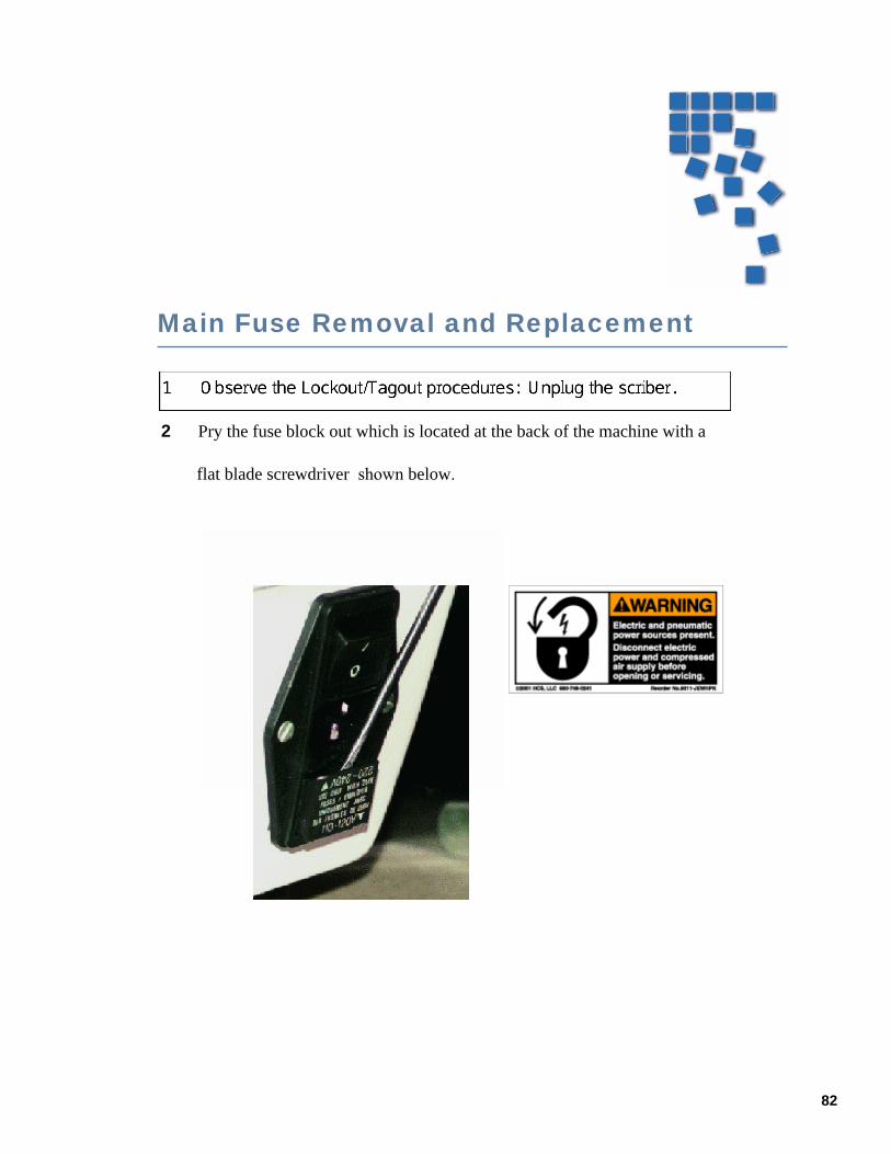
82
Main Fuse Removal and Replacement
2 Pry the fuse block out which is located at the back of the machine with a
flat blade screwdriver shown below.

83
3
Inspect the fuse, and if needed, replace with same type and rating.
4
Replace the fuse block back into the housing , making sure that the correct voltageis selected by matching the two arrows, below.

Consumables List For Loomis Scribe Equipment The following tables contain lists of consumables that are frequently used on Loomis scribe and break equipment. These lists change over time, and may no longer be complete. Also, prices change without notice. Therefore, there are no prices listed with the parts in the tables.
2500-0722 GRIP RINGS GRP2620-4 YELLOW & GREEN
2500-0827 GRIP RINGS GRP2620-5 BLACK AND WHITE
2500-1006 GRIP RINGS GRP2620-6 BLACK AND WHITE
7550-0092 SQUARE FRAMES LARGE
4100-0027 TAPE DISPENSER
3900-0006 MICROSCOPE BULBS FROSTED
3900-0005 MICROSCOPE BULBS CLEAR
3200-0335 SQUARE FRAME TAPE 36 YD (PN#443PC 3M-R.S. HUGHS )
3200-0338 UV TAPE (FURKAWA UC353EP110 (SWISS CROSS 8.5")
3200-0351 POLISHED 2 MIL VINYL (ROBECCO) ROLL GREEN
3200-0356 LOOMIS UV CURED FOR LASERS
3200-0357 LOOMIS SWISS CROSS 8.5" WITH PAPER BACKING BLUE
3200-0358 LOOMIS UV CURED FOR LASERS 8.5" (3-4 MINUTE TREAT)
3200-0360 V8-T TAPE SWISS CROSS 8.5" (NITTO DENKO)
3200-0361 SPV-224 CLEAR WITH PAPER BACKING
3200-0362 V8-T TAPE SWISS CROSS 8.0"
3200-0363 SPV-224 CLEAR 8.5: ROLLS
3200-0364 SPV-224 WITH PLASTIC LINER BLUE 8.5"
3200-0365 SPV-224 WITH PLASTIC LINER WHITE CLEAR BACKING
3200-0366 SPV-224 9x9" SQUARES LOW TACKL TAPE
3200-0367 SC TAPE FOR CREE, 4-5 MINUTE TREAT PLASTIC BACKING
3200-0368 18733 SEC ON PAPER BACK, LOW TACK
3200-0369 DT100, OPEC (NEPTCO)
3200-0371 SWISS CROSS TAPE (ULTRON 1002)

84
Scribe Tool Application Chart
Sorted by Loomis
Scribe Tool #
Angle Setting
(degrees) Material ApplicationMaterial Thickness
(microns | inches)
7050-0002 39 111 Oriented Silicon 50-300 .002-.0127050-0003 45 Sapphire 50-150 .002-.0067050-0004 39-43 GaAs 150-500 .006-.0207050-0005 42 Sapphire 50-150 .002-.0067050-0008 17 Ceramic 50-300 .002-.0127050-0018 39-43 GaAs 50-150 .002-.0067050-0027 20 GaAs, InP 50-150 .002-.0067050-0038 17 Ceramic, Glass 50-300 .002-.0127050-0055 25-30 Sapphire, InP, GaAs 50-250 .002-.0107050-0060 27 Glass 50-1000 .002-.0407050-0068 10-13 100 Oriented Silicon 50-375 .002-.015
Sorted byMaterial Application
Material Thickness
(microns | inches)
LoomisScribe Tool #
Angle Setting
(degrees)
100 Oriented Silicon 50-375 .002-.015 7050-0068 10-13111 Oriented Silicon 50-300 .002-.012 7050-0002 39Ceramic 50-300 .002-.012 7050-0008 17Ceramic, Glass 50-300 .002-.012 7050-0038 17GaAs 50-150 .002-.006 7050-0018 39-43GaAs 150-500 .006-.020 7050-0004 39-43GaAs, InP 50-150 .002-.006 7050-0027 20Glass 50-1000 .002-.040 7050-0060 27Sapphire 50-150 .002-.006 7050-0003 45Sapphire 50-150 .002-.006 7050-0005 42Sapphire, InP, GaAs 50-250 .002-.010 7050-0055 25-30
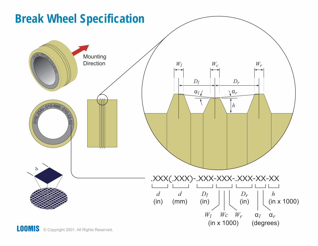
Wl
Dl Dr
h
Wc Wr
αrαl
�XXX(�XXX)��XXX�XXX��XXX�XX�XX
d
d
(in)
d
(mm)
Dl
(in)
Wl Wc Wr αl αr
Dr
(in)
h
(in x 1000)
(in x 1000) (degrees)
Mounting
Direction
Break Wheel Specification
© Copyright 2001. All Rights Reserved.
.010(.25
4)-.0
10-666-.010-22-0
2
.010
(.254)-.010-666-.0
1
0-22-02

86
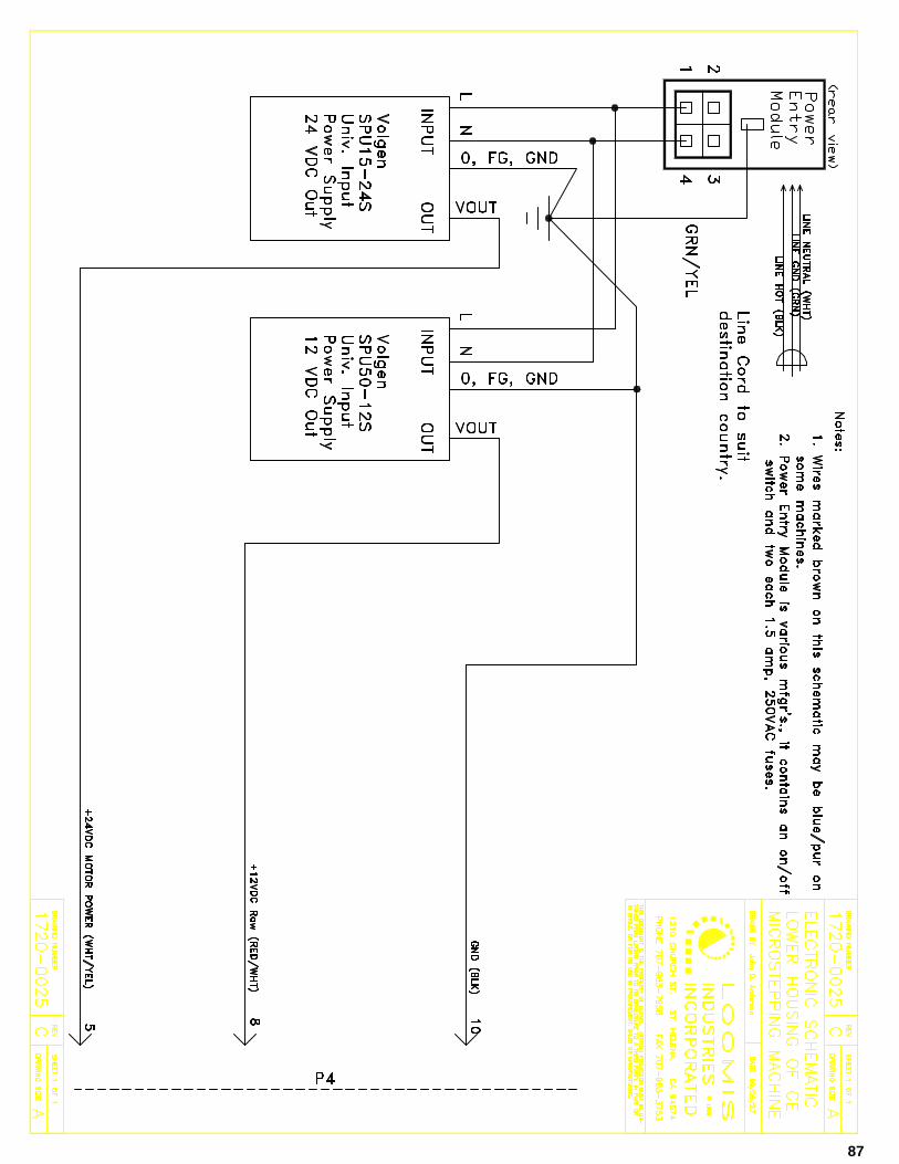
44
44
44
87
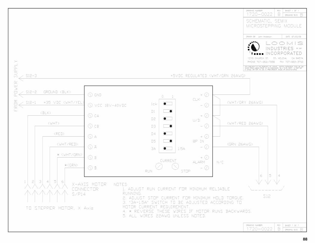
88
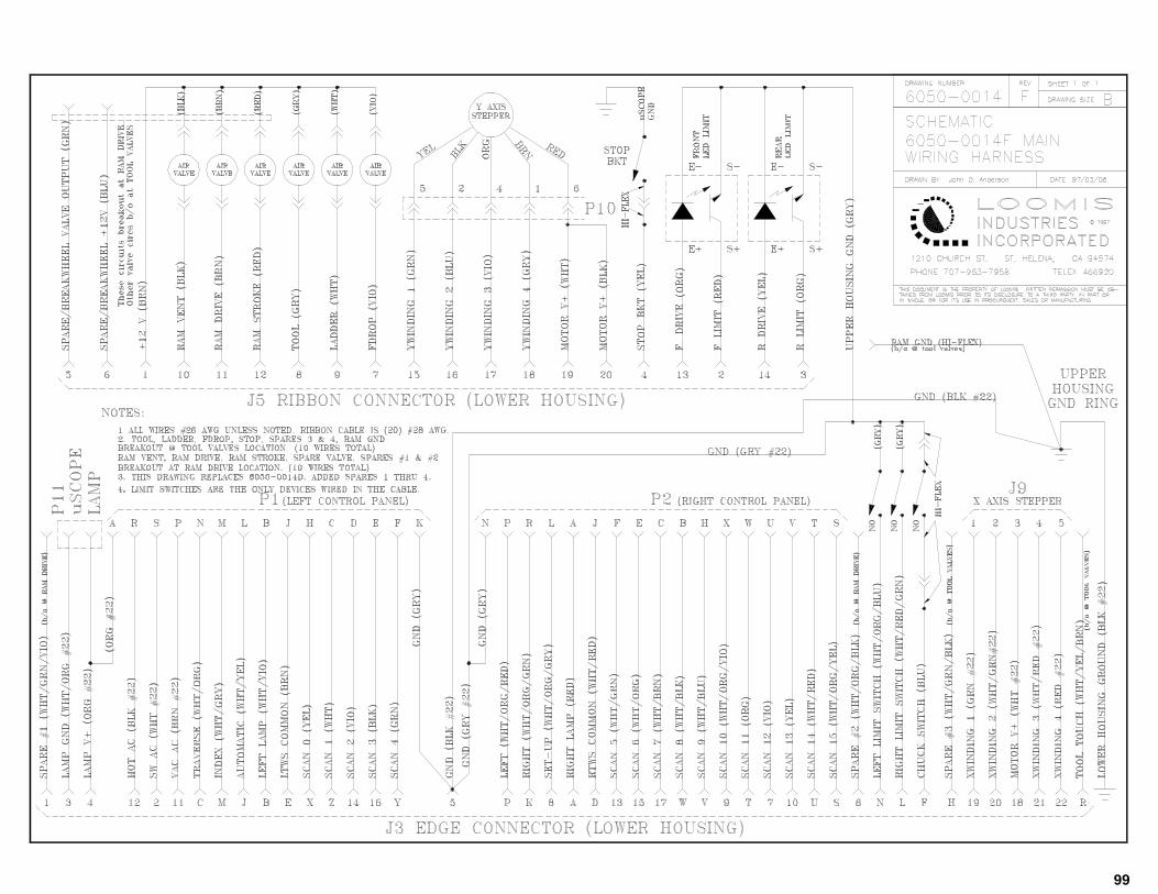
99
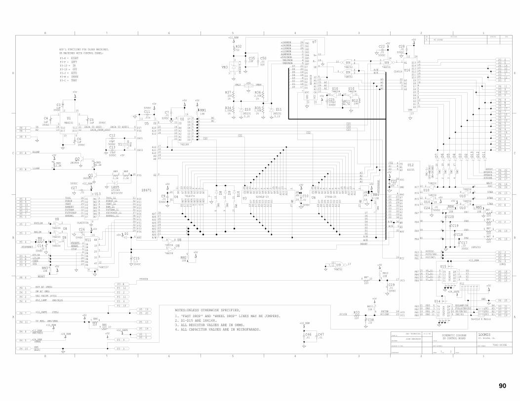
44
44
44
44
90
.01C10
.01C9
.01C7
.01C29
.01
C22
.01C23
.01C28
100pfC25
.01C24
P5 1
1
9
SW1
813
SW1
912
SW1
1011
SW1
120
SW1
219
SW1
318
SW1
417
A12
A11
A10A9A8A7A6A5A4A3A2A1A0OECS
WED0D1D2D3D4D5D6D7
2764A-25U6
19 18 17 16 15 13 12 11 27
14
2628
12232124253456789102220
10KRN41
6
10KRN11
2
74HC04
U81213
74HC04
U843
74HC04
U821
74HC04
U889
74HC04
U865
74HC04U10
12 1374HC04U10
10 11
74HC04
U108 9
74HC04
U106 5
74HC04
U104 3
74HC04
U102 1
7.3728
Y110pf
C12
10pf
C13
.01u
C11
.01
C27
.01
C26
2.2KRN9
78
220RN6
5 6
220
RN79 10
4.7KR11
RN77 8
220
RN75 6
220
RN73 4
220
RN71 2
220
220
RN67 8
220RN6
9 10
20KR12
P25P27P26
R/W
P20P21P22P23P24
P31P32P33P34
RSTAD0AD1AD2AD3AD4AD5AD6AD7
ASP35
OSC2
OSC1
P30P37
A8A9
A10A11A12
A13A14A15
DSU545
3
2
10
3638
313233343537
39123029
6 72122232425262728
9
1314151617
181920
8111
D10D8
D1D9
D11
D12
D13
D2D3D4D5D6D7
A12
A11
A10A9A8A7A6A5A4A3A2A1A0OECS
WED0D1D2D3D4D5D6D7
6264LP-15U3
19 18 17 16 15 13 12 11 27
14
2628
12232124253456789102220
AS
AD0
AD1
AD2
AD3
AD4
AD5
AD6
AD7
A0A1A2A3A4A5A6A7
74LS374U4
20
10
18 17 14 13 8 7 4 3
1
25691215161911
D7D6D5D4D3D2D1D0A0
A1A2A3A4
CS
74S188
U28
15
1413121110 1
2345679
16
+
1uFC5+
1uFC4
+ 1uFC6
+1uFC3
+
.33C14
+
1.5C15
+C20
+C19
+C18
+
.33C17
P3 8P3 FP3 NP3 L
P3 B
P3 A
P3 R
P3 20P3 21P3 22
P3 CP3 MP3 J
P3 P
P3 K
P3 E
P3 D
P3 V
P3 9
P3 T
P3 X
P3 Z
P3 14
P3 16
P3 Y
P3 13
P3 15
P3 17
P3 W
P3 7
P3 10
P3 UP3 S
P3 12
P3 2
P3 11
P3 4
P3 18
P3 5
1
7
P3 19
P5 4
P5 3
P5 2
P5 5P5 7P5 12P5 11P5 10P5 9P5 8
P5 6
P5 15P5 16P5 17
P5 19P5 20
P5 18
P5 14
P5 13
P8 2P8 1
P8 9
P8 6
Q12N3904
Q22N3904
10KRN2
1
6
10KRN3 4
RN101
510K
1
8
ULN2003A
IN1IN2IN3IN4IN5IN6IN7O7
O6O5O4O3O2O1
U1316151413121110
8
7654321
9
74HC02
U9 132
74HC02
U94 65
74HC02
U9 131211
10K
RN415
ZR404-5.0
VR3
1
2
3
S15S14S13S12S11S10S9S8S7S6S5S4S3S2S1S0
INH
A0A1A2A3
AL
CD4514 U16
1
222132
23
11910876541817201914131615
2412
P4 9
P4 1
P4 3
P4 2
P4 4
P4 7
P4 11
P4 5
P4 8
P4 10
P6 18
P6 19
P6 15
P6 24P6 16
P6 17P6 20P6 21P6 22
P6 2
P6 4
P6 5
P6 6
P6 7
P6 9
P6 10
P6 11
P6 12
P6 8
P6 1
P6 3
P6 13
P6 14
P6 25
SW1
714
Q1Q2Q3
I1I2I3I4 Q4
ULN2064
U1472169
451213
111436
8 1
Q1Q2Q3
I1I2I3I4 Q4
ULN2064
U1572169
451213
111436
8 1
10KRN10 1
6
74HC02
U910 98
T1IR10R1I
T10
MAX232
U11
31413
15 6
12115
4162
10K
RN5 15
AB
4Y
3Y
2Y
1Y
4B4A3B3A2B2A1B1A
74HC157
U112356
11101413
8 15
12
9
7
4
116
R-
R+
IN6IN5IN4IN3IN2IN1IN0
IN7
EOC
D0D1D2D3D4D5D6D7
CKA2A1A0ALST
OE
GND
VCC
ADC0808
U726272812345
212019188
151417
7
13 11
10232425226
9
16
12
P12
1 2 3 4 5 6
JP1
JP3JP2
.1UFC35
750R32
2.2K
RN91 2
2.2K
RN93 4
2.2KRN9
56
5.1V1N5231
Z10
PC1PC0
PC3
PC5
PC2
PB0PB1PB2PB3
PB4PB5PB6PB7
PA1PA2PA3
PA4
PA5
PA6
PA7
PC4
PC6
PC7
RST
RD
WR
D0D1D2D3D4D5D6D7PA0
GND
VCC
A0A1CS
82C55
U12689
26
7
42728293031323334
36
5
35
16
17
1415 18
192021
22232425
321
40
39
38
37
13
12
11
10
LT1049LED5
+
.33C38
1
3
1
4
1
8
1
9
1
2
1
7
1
6
1
5
1
4
1
3
1
7
1
6
1
2
1
5
1
8
1
5
1
3
1
3
1
3
1
4
1
4
1
2
P3 6
220
R33
.01C46
.01C47
2.00KR36
JP8
1.00KR34
200R37
1.00KR35
5.1V1N5231
Z11
50V.01C50
LTWS
CS3
CS5
R/W
R/W
R/W
CS0
A0
A0
A0
A0
A2
A2
A2
A3
A3
D4
D4
D4
CS2
PDROP_LL
CS1
D3
D3
D3
RESET
RLAMP
D6
D6
D6
VENT_LL
+24_RAW
ASOUT
D2
D2
D2
TXRD
X1
TOOLPDROPVENT
LTLIM
FSTRAMFSTPDROPBRKWHL
RESET
CHKS
RRLIM
X2X3
FRTLIM
STOPBRKTSTOPREARLFRONTL
SUS
POTU/DN\
DSC
POTINC\
TOOL_LL
XFENCEYFENCESCRIBE
WAIT
Y4
RTWS
YTWS
+12_SAFE
+12_SAFE
Y3Y2Y1
D0
D0
D0
D1
D1
D1
PB0PB1PB2PB3
W/R
W/R
W/R
D5
D5
D5
D7
D7
D7
CS4
CS4
A1
A1 A1
A1
+12RMON
ALMPMON+12SMON
+24SMON
+5VDCMON
LLAMP
+12_RAW
+12_RAW
+12_RAW
+12_RAW
+12_RAW
VMHVMONVMLVMON
GND
GND
VMHVVMLV
+24_SAFE
X4
RAMDRV RAM_LL
TTOUCH
+5V
+5V
+5V
+5V
+5V
+5V+5V
+5V
+5V
+5V
+5V
+5V
+5V
+5V
+5V +5V
+5V+5V+5V
+5V
+5V
+5V
+5V
+5V
PA7SW
+24RMON
PA6
Y4_LLY3_LL
PC1IN
PA7
Y2_LL
PA4
Y1_LL
PA5
POTCS\
PC1INP
ADJ_LAMP
RTLIM
2. D1-D15 ARE 1N4148. On=Old X Motor
+12_RAW
+24_RAW
ACTIVITY
(WH/RED)
(BRN)
1. "FAST DROP" AND "WHEEL DROP" LINES MAY BE JUMPERS.
NOTES:UNLESS OTHERWISE SPECIFIED,
4. ALL CAPACITOR VALUES ARE IN MICROFARADS.3. ALL RESISTOR VALUES ARE IN OHMS.
SW1-1:
OFF=METRIC
ON=INCHES
Z8671
50VDC
(ORG)
(BLK)
6-11-98
7040-0030E
2
ST. HELENA, CA.
CAD TECHNICAL
JOHN ANDERSON Z8 CONTROL BOARDLOOMIS
1
AS ISSUEDA
DD
CC
BB
AA
SHEET OF
DATEAPPROVEDREVISIONSSYM
PART NUMBER
SCALE
NEXT ASSEMBLY
TITLE
SCHEMATIC DIAGRAM
SUPERSEDES
RELEASED TO PROD.
ENGINEER
DRAWN BY
1
1
2
2
3
3
4
4
5
5
6
67
8
8
7
7,
7
14
14
TRAVINDEXAUTOOUTIN
LEFTRIGHT
P3-C =P3-M =P3-J =P3-18 =P3-19 =P3-P =P3-K =
OR MACHINES WITH CONTROL PANEL:ADD’L FUNCTIONS FOR OLDER MACHINES,
UP/DN/X2INC/X1
FULLSTEP/X3BSLAMP/X4
485ENABLE
DATA TO HOST DATA TO HOSTI
(WH/BLK)
(YEL)
FSTPDROP_LLBRKWHL_LL
FSTRAM_LL
DATA_FROM_HOST
5V REG. (WH/GRN)
VAC VALVE (VIO)
SW AC (WH)
HOT AC (RED)
NCNC
35VDC
35VDC
35VDC
35VDC
50VDC50VDC
50V
(4PLCS)35VDC
50VDC
50VDC
50VDC50VDC
35VDC
50VDC
35VDC
50VDC
MHz
50VDC
50VDC
50VDC
50VDC
1% 1%
1% 1%

91
+.01FC2
P3 3
VCC
VI
VR
VWIP
GND
U18
721
4 5
6
3
8
X9312W
P3 HP3 1
RN10
1 3
JP7
P15
JP5
Q1Q2Q3
I1I2I3I4Q4
ULN2064
U1972
169
4 5 12 13
111436
81
.1uFC31
+4700uFC30
RN6
12
220
RN6
34
220
2.2KRN9
910
1.00KR26
1.00KR24
4.99KR28
1.00KR27
4.99KR29
7.15KR30
7.15KR31
Z2
1N5231
1.00KR20
Z3
1N5231
1.00KR21
Z4
1N5231
1.00KR22
Z5
1N5231
1.00KR23
Z61N5231
Z9
1N5242
R251.00K
P161234
P1312345678910
10K
RN10
1 2
RN10
1 4
RN81
4
10KRN81
2RN8
1
6RN8
1
3RN8
1
5
DE
DI
RD
RE\GNDGND
VCCNCY
Z
A
B
NCNC
U1718
11
12
10
9
13
14
4
5
2
3
67
MAX1482
D14
1N4148
D15
1N4148
74HC04U8
1011
LED4LT1049
LED1LT1049
LED3LT1110
F2
F3
LED2LT1110
LED6LT1110
Z8
1N5242
Z7
5.1V
JP6
.01C37
P141 23 45 67 89 10
11 1213 1415 1617 1819 2021 2223 2425 2627 2829 3031 3233 34
VF
VINGND ON\
VOUT
VR2
1
3 5
2
4
LM2575-ADJ
1N5817D16
L1
450uH
+
16V1000uFC1+C32
330uF
10.00KR18
1.00KR17
.1uFC36
CW
R195K
+
330uFC34
450uH
L2
1N5817D17+
330uFC33
F1
RY1
4
3
6 5
1
2
1111
VF
VINGND ON\
VOUT
VR1
1
3 5
2
4
LM2575-5.0
.01C41
.01C40
.01C42
.01C43
.01C44
.01C45
JP4
Z1
1N5231
50V.1C48
50V.1C49
+24_RAW
+24_RAW
TOOLPDROP
VENT
LTLIM
FSTRAM
FSTPDROP
BRKWHL
RRLIMFRTLIMSTOPBRKT
POTU/DN\POTINC\
Y4
+12_SAFE
+12_SAFE
+12_SAFE
+12_SAFE
+12_SAFE
+12_SAFE
+12_SAFE
+12_SAFE
Y3Y2Y1
+12RMON
ALMPMON+12SMON
+24SMON
+5VDCMON
LLAMP
+12_FUSE
RELAYOUT
+12_RAW
+12_RAW+12_RAW
+12_RAW
GND
GND
GND
GND
GNDGND
+24_SAFE
+24_SAFE
+24_SAFE
PA4OUT
PA4OUT
PA5OUT
PA5OUT
RAMDRV
TTOUCH
+5V
+5V
+5V
+5V
+5V
+5V
+5V
+5V
+5V
+5V
PA7SW
+24RMON
PA6PC1IN
PA6SWPA7
TSLAMP
TSLAMP
PA4
+24_FUSE
PA5
POTCS\
ADJ_LAMP
ADJ_LAMP
RTLIMU12-38
Relay Locked On
No Emergency SW
DATA TO HOSTI
MANUAL LAMP VAUTO LAMP V
U12-40U12-39
U12-14
U12-37
REGULATED SUPPLY
U12-3U12-2U12-1
U12-4
U5-4
U1-12DATA FROM HOST
DATA TO HOST X
DATA TO HOST
6-11-98
7040-0030E
22
8
8
7
7
6
6
5
5
4
4
3
3
2
2
1
1
DRAWN BY
ENGINEER
RELEASED TO PROD.
SUPERSEDES
SCHEMATIC DIAGRAM
TITLE
NEXT ASSEMBLY
SCALE
PART NUMBER
SYM REVISIONS APPROVED DATE
SHEET OF
A A
B B
C C
D D
A AS ISSUED
LOOMISZ8 CONTROL BOARDJOHN ANDERSON
CAD TECHNICAL
ST. HELENA, CA.
TSLamp Locked On
Auto TSLamp
LAMPV+
LAMPV+
485ENABLE\
485ENABLE
1.2-7.5 VDC
BSLAMP/X4
63V35V
RS-4
85 P
ORT
On=<30VDC PS
+24VDC
RS485 On
+12VDC
U1-11
10 P
IN S
HROU
D
12V
12V
5VDC
RELAY ON
4Amp,2AG
0.75Amp,2AG
1%
1%1%
1%1%1%
1%
1% 1% 1% 1% 1% 1%
1%
Z1-Z6 ARE 1N5231, 5.1 VOLT, 500mW ZENER.
POWER OUT


![[LSD]LSD - Complete FBI Blotter Microgram Analysis Manual (1987)](https://img.pdfslide.us/doc/110x75/55cf98fa550346d0339acf6a/lsdlsd-complete-fbi-blotter-microgram-analysis-manual-1987.jpg)


![[LSD]Remembrances of LSD Therapy Past-Betty Grover Eisner, org](https://img.pdfslide.us/doc/110x75/577dab601a28ab223f8c57f0/lsdremembrances-of-lsd-therapy-past-betty-grover-eisner-org.jpg)