Embed Size (px)
Citation preview

Operator’s Manual
LS-Series Compact Chiller
110-445 09.01.11

110-445 1
Table of ContentsTable of ContentsTable of ContentsTable of Contents IntroductionIntroductionIntroductionIntroduction .................................................................................................................................................................................................................................................................................................................................................................................................................................................................................................................................................................................................................................... 2222 General InformationGeneral InformationGeneral InformationGeneral Information ................................................................................................................................................................................................................................................................................................................................................................................................................................................................................................................................................................................ 2222 General Safety Information............................................................................................................................................................... 2 Safety Recommendations ................................................................................................................................................................. 3 Unpacking Your Chiller ...................................................................................................................................................................... 3 Regulatory and Compliance Testing................................................................................................................................................ 3 Contents .............................................................................................................................................................................................. 3
ContrContrContrControls and Componentsols and Componentsols and Componentsols and Components ........................................................................................................................................................................................................................................................................................................................................................................................................................................................................................................................................ 4444 Installation and StartupInstallation and StartupInstallation and StartupInstallation and Startup ........................................................................................................................................................................................................................................................................................................................................................................................................................................................................................................................................................ 5555 Site Requirements.............................................................................................................................................................................. 5 Ambient Temperature and Relative Humidity............................................................................................................................ 5 Location........................................................................................................................................................................................... 5 Clearance ........................................................................................................................................................................................ 5
Electrical Power.................................................................................................................................................................................. 5 Optional RS232 Serial Output .......................................................................................................................................................... 5 Plumbing.............................................................................................................................................................................................. 5 Process Piping................................................................................................................................................................................ 5 Fluid Filter ....................................................................................................................................................................................... 6 Reservoir Drain............................................................................................................................................................................... 6
Closed System or Cooling Coil Setup............................................................................................................................................... 6 Startup................................................................................................................................................................................................. 7 Process Coolant ............................................................................................................................................................................. 7 Electrical Power .............................................................................................................................................................................8 Starting Process Fluid Flow..........................................................................................................................................................8
Normal OperationNormal OperationNormal OperationNormal Operation ................................................................................................................................................................................................................................................................................................................................................................................................................................................................................................................................................................................................ 8888 Selecting the Temperature Unit (°C or °F) .....................................................................................................................................8 Displaying and Adjusting the Set Point ........................................................................................................................................... 9 Setting Operational Parameters ...................................................................................................................................................... 9 High Temperature Limit (H-##) ................................................................................................................................................... 9 Low Temperature Limit (L-##)....................................................................................................................................................10 Auto-Refrigeration Temperature (A ##)....................................................................................................................................10 Specific Heat (P.##) .....................................................................................................................................................................10 Communications Baud Rate (PC##)...........................................................................................................................................10 Temperature Calibration (C #.#)..................................................................................................................................................11 Password (Pd00)............................................................................................................................................................................11
Enabling/Disabling the Local Lockout (LLO) ..................................................................................................................................11 Display, Error and Fault MessagesDisplay, Error and Fault MessagesDisplay, Error and Fault MessagesDisplay, Error and Fault Messages ............................................................................................................................................................................................................................................................................................................................................................................................................................................................................ 12121212
Routine Maintenance and TroubleshootingRoutine Maintenance and TroubleshootingRoutine Maintenance and TroubleshootingRoutine Maintenance and Troubleshooting .................................................................................................................................................................................................................................................................................................................................................................................................................... 13131313 Magnetic Drive Centrifugal Pump ...................................................................................................................................................13 Condenser, Air Vents, and Reusable Filter ....................................................................................................................................13 Fluid Level ..........................................................................................................................................................................................13 Temperature Calibration ..................................................................................................................................................................13 Cleaning Exterior SurfacesCleaning Exterior SurfacesCleaning Exterior SurfacesCleaning Exterior Surfaces............................................................................................................................................................14 Troubleshooting.................................................................................................................................................................................14
Technical InformationTechnical InformationTechnical InformationTechnical Information ................................................................................................................................................................................................................................................................................................................................................................................................................................................................................................................................................................ 15151515 Model LS51/LS53 60Hz Compact Chiller Specifications..............................................................................................................15 Model LS52 50Hz Compact Chiller Specifications .......................................................................................................................16 General Information & Specifications.............................................................................................................................................17 RS232 Serial Communications (Optional)......................................................................................................................................18
Equipment Disposal (WEEE Directive)Equipment Disposal (WEEE Directive)Equipment Disposal (WEEE Directive)Equipment Disposal (WEEE Directive) ........................................................................................................................................................................................................................................................................................................................................................................................................................................................ 19191919 Service and Technical SupportService and Technical SupportService and Technical SupportService and Technical Support .................................................................................................................................................................................................................................................................................................................................................................................................................................................................................................... 19191919
Replacement Parts and AccessoriesReplacement Parts and AccessoriesReplacement Parts and AccessoriesReplacement Parts and Accessories ............................................................................................................................................................................................................................................................................................................................................................................................................................................................ 20202020 PolyScience Chiller FluidsPolyScience Chiller FluidsPolyScience Chiller FluidsPolyScience Chiller Fluids .................................................................................................................................................................................................................................................................................................................................................................................................................................................................................................................................... 21212121
WarrantyWarrantyWarrantyWarranty .................................................................................................................................................................................................................................................................................................................................................................................................................................................................................................................................................................................................................................................... 21212121

110-445 2
IntroductionIntroductionIntroductionIntroduction
The LS-Series Compact Chiller provides cooling power for demanding applications and serves as an economical alternative to tap water cooling systems. It features a microprocessor-based controller, digital temperature display (°C or °F), and simple operation and maintenance.
To optimize cooling efficiency and performance, this sophisticated Chiller also features a modulated refrigeration system. As a result, temperature stability is greatly enhanced and compressor life extended.
The Chiller is equipped with either a magnetic drive centrifugal pump or a turbine pump. Wetted parts within the recirculation system are brass, copper, stainless steel, EPDM rubber, Alcryn, nylon, PVC, and polyethylene.
General InformationGeneral InformationGeneral InformationGeneral Information
General SGeneral SGeneral SGeneral Safety Informationafety Informationafety Informationafety Information
When installed, operated, and maintained according to the directions in this manual and common safety procedures, your Chiller should provide safe and reliable heat removal. Please ensure that all individuals involved in the installation, operation, or maintenance of this unit read this manual thoroughly prior to working with the unit.
This symbol alerts you to wide range of potential dangers.
This symbol advises you of danger from electricity or electric shock.
This symbol marks information that is particularly important.
This symbol indicates alternating current.
/
These symbols on the Power Switch / Circuit Breaker indicate that they place the main power supply ON / OFF.
This symbol on the Power Switch indicates that it places the unit in a standby mode. It DOES NOT fully disconnect the unit from the power supply.
This symbol indicates a protective conductor terminal.
Read all instructions pertaining to safety, setRead all instructions pertaining to safety, setRead all instructions pertaining to safety, setRead all instructions pertaining to safety, set----up, and operation. up, and operation. up, and operation. up, and operation. Proper operation and maintenance is the Proper operation and maintenance is the Proper operation and maintenance is the Proper operation and maintenance is the user’s responsibility.user’s responsibility.user’s responsibility.user’s responsibility.
110-445 3
Safety RecommendationsSafety RecommendationsSafety RecommendationsSafety Recommendations
To prevent injury to personnel and/or damage to property, always follow your workplace’s safety procedures when operating this equipment. You should also comply with the following safety recommendations:
• Always connect the power cord on this unit to a grounded (3-prong) power outlet. Make certain that the outlet is the same voltage and frequency as your unit.
• Never operate the unit with a damaged power cord.
• Always turn the unit OFF and disconnect Mains power before performing any maintenance or service.
Unpacking Your ChillerUnpacking Your ChillerUnpacking Your ChillerUnpacking Your Chiller Your Chiller is shipped in a special carton. Retain the carton and all packing materials until the unit is completely assembled and working properly. Set up and run the unit immediately to confirm proper operation. Beyond one week, your unit may be warranty repaired, but not replaced. If the unit is damaged or does not operate properly, contact the transportation company, file a damage claim and contact the company where your unit was purchased immediately.
CAUTION:CAUTION:CAUTION:CAUTION: Keep unit upright when moving. Be sure to follow your company’s procedures and practices regarding the safe lifting and relocation of heavy objects.
RegulatoryRegulatoryRegulatoryRegulatory and Compliance Testing and Compliance Testing and Compliance Testing and Compliance Testing
CSA UL (60Hz units)CSA UL (60Hz units)CSA UL (60Hz units)CSA UL (60Hz units)
CAN/CSA C22.2 No. 61010-1-04 — Safety Requirements for Electrical Equipment for Measurement, Control and Laboratory Use, Part I: General Requirements.
CAN/CSA C22.2 No. 61010-010-04 — Safety Requirements for Electrical Equipment for Measurement, Control and Laboratory Use - Part 2-010: Particular Requirements for Laboratory Equipment for the Heating of Materials.
UL Std No. 61010-1 — Electrical Equipment for Laboratory Use, Part I: General Requirements.
UL Std No. 61010A-2-010 — Electrical Equipment for Laboratory Use, Part 2: Particular Requirements for Laboratory Equipment for the Heating of Materials.
CE (50Hz units)CE (50Hz units)CE (50Hz units)CE (50Hz units)
EC Low Voltage Directive 2006/95/EC
EC Electromagnetic Compatibility Directive 2004/108/EC
IEC 61010-1-2001
IEC 61326:2005 / EN 61326 : 2006
Contents Contents Contents Contents
The following items have been included with your Chiller:
• Operator’s Manual
• IEC Power Cord
• Two sets of Inlet/Outlet Adapters: 1/2 inch NPT to 1/2 inch hose barb; 1/2 inch NPT to 5/8 inch hose barb
110-445 4
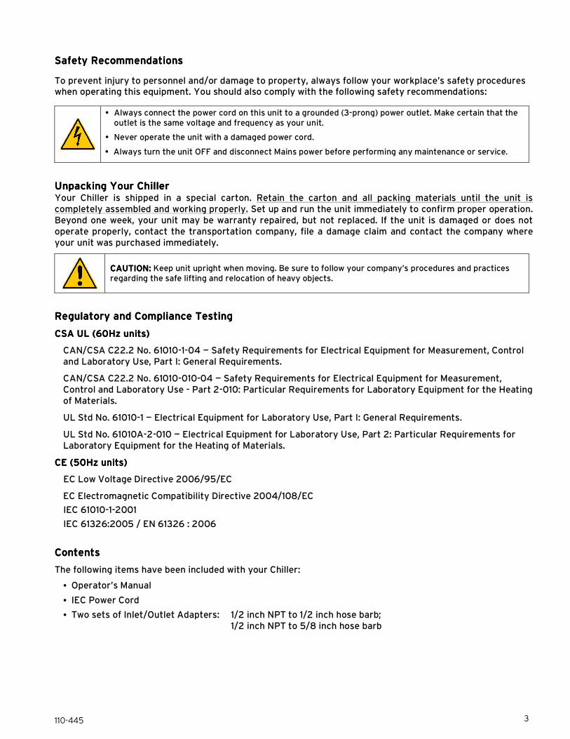
Controls and ComponentsControls and ComponentsControls and ComponentsControls and Components
NOTE:NOTE:NOTE:NOTE: When controlling at the set point temperature, it is not uncommon for both the heating and cooling LEDs to be lit simultaneously.
Fluid Inlet
Fluid Outlet
IEC Power Connection
RS-232 Connection (optional; not shown)
Reservoir Cap Circuit Breaker / Power Switch Up & Down Arrow Buttons
Drain
Temperature Units LEDs
Temperature Display
Heating & Cooling LEDs
Set Button
On/Off Button
Fluid Level Indicator
Air Filter Compartment
Identification Label

110-445 5
Installation and StartupInstallation and StartupInstallation and StartupInstallation and Startup
WARNING: WARNING: WARNING: WARNING: Be sure all power is off before proceeding.
Site RequirementsSite RequirementsSite RequirementsSite Requirements
Ambient Temperature and Relative HumidityAmbient Temperature and Relative HumidityAmbient Temperature and Relative HumidityAmbient Temperature and Relative Humidity
The Chiller is designed for indoor installation in ambient temperatures between 5° and 35°C (41° and 95°F); relative humidity should not exceed 80% (non-condensing).
LocationLocationLocationLocation
The Chiller should be installed on a strong, level surface. It should be located as close to possible to the process requiring cooling. It should not be installed closer than 1.4 meters (4 feet) to a heat-generating source, such as heating pipes, boilers, etc. If possible, the Chiller should be located near a suitable drain to prevent flooding in the event of leaks. Do not place it where corrosive fumes, excessive moisture, excessive dust, or high room temperatures are present.
NOTE:NOTE:NOTE:NOTE: The Chiller may be located at a level below that of the equipment being cooled. As long as the process remains closed, overflow will not occur when adding cooling fluid to the Chiller reservoir.
ClearanceClearanceClearanceClearance
Adequate clearance should be allowed on the front, sides, top, and rear of the Chiller for access to connections and components. The front and side vents of the Chiller must be a minimum of 21 cm (8 inches) away from walls or vertical surfaces so air flow is not restricted.
ElectricaElectricaElectricaElectrical Power l Power l Power l Power
An IEC power cord is provided with the Chiller. It should be attached to the receptacle on the rear of the enclosure. Make sure that the power outlet used for the Chiller is properly grounded and matches the voltage and frequency indicated on the identification label on the back of the Chiller.
To help prevent voltage drops, position the Chiller as close as possible to the power distribution panel. Avoid voltage drops by using a properly grounded power outlet wired with 14 gauge or larger diameter wire.
The use of an extension cord is not recommended. However, if one is necessary, it must be properly grounded and capable of handling the total wattage of the unit. The extension cord must not cause more than a 10% drop in voltage to the Chiller.
WAWAWAWARNING: RNING: RNING: RNING: DO NOT plug the Chiller into the electrical outlet until the unit is ready for Startup....
Optional RS232 Serial OutputOptional RS232 Serial OutputOptional RS232 Serial OutputOptional RS232 Serial Output
This option allows you to remotely control the Chiller and/or output temperature readings to an external recorder or other auxiliary device. The maximum communications distance for Chillers equipped with the RS232 option is 15 meters (50 feet). A 9-pin D-connector is provided on the rear of the instrument enclosure for this connection. See the Technical Information section for the RS232 serial communication protocol.
Plumbing Plumbing Plumbing Plumbing
Process PipingProcess PipingProcess PipingProcess Piping
The Chiller has two internally threaded (0.5 inch ID NPT) fittings on the rear of the instrument housing for the process fluid connections. Two sets of 90° barbed hose adapters (0.5 inch and 5/8 inch) are supplied with the unit for connecting these fittings to the process piping.
To maintain a safe workplace and avoid leaks, special care should be taken when choosing hoses and connectors for the Chiller. It is the user’s responsibility to ensure that the tubing and fittings connected to the
110-445 6
Chiller are compatible with the fluid, temperature, and pressure being used.
• Pressure Ratings — Hoses should be able to withstand the largest pressure that they will encounter.
• Flexible Tubing — Avoid tubing that will expand and take up fluid volume when operating at the desired pressure.
• Hose Diameter — Process piping/hosing with a diameter smaller than 0.5 inch ID can be used if desired. However, keep in mind that using smaller diameter hosing increases pressure and reduces flow in the circulating system and may result in a flow alarm. The minimum recommended tubing size is 3/8 inch ID.
• Couplings and Clamps — The use of screw-tightened hose clamps is necessary on all joints to insure good, tight connections. Quick connectors are not recommended as they have the potential for restricting flow rate.
Fluid FilterFluid FilterFluid FilterFluid Filter
If particulate matter may be present in the fluid, the installation of a 50 micron filter on the chiller inlet is recommended.
50 micron fluid filter: Part number 510-519
Reservoir DrainReservoir DrainReservoir DrainReservoir Drain
A 0.5 inch NPT connection is provided for the reservoir’s gravity drain. It should be piped to a drain or receptacle positioned below the bottom of the drain. If a receptacle is used, be sure it is of sufficient volume to hold all the water in the reservoir, process, and process lines.
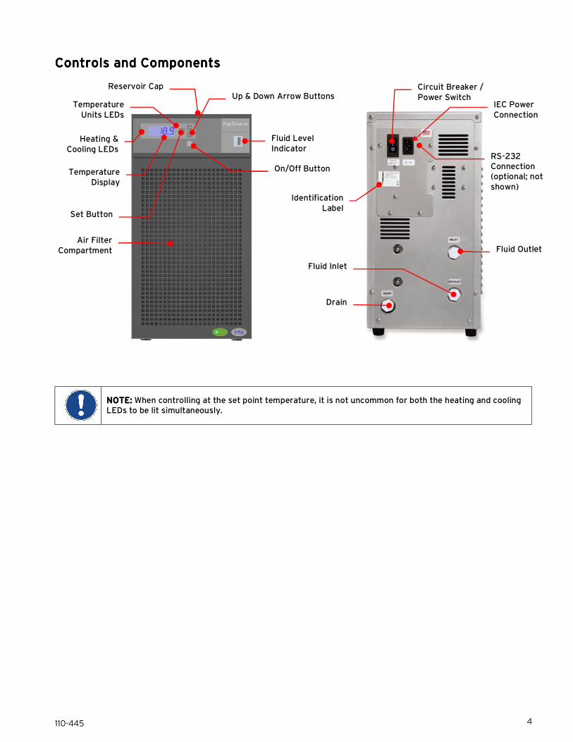
Closed System or Cooling Coil SetupClosed System or Cooling Coil SetupClosed System or Cooling Coil SetupClosed System or Cooling Coil Setup
Connect the Chiller’s inlet and outlet to the external apparatus with hoses or pipes. The direction of the flow through the system can be controlled by the way the connections are made. Fluid is drawn into the Chiller through the “Inlet” connection; fluid is pumped out of the Chiller through the “Outlet” connection.
NOTE:NOTE:NOTE:NOTE: If the Chiller is connected to an external apparatus with a built-in shutoff, an external bypass loop assembly may be needed. This bypass assembly continues flow circulation to and from the pump even though the main flow to the external apparatus has been blocked.
External bypass loop assembly: Part number 510-147

110-445 7
StartupStartupStartupStartup
Process CoolantProcess CoolantProcess CoolantProcess Coolant
Suitable Fluids
WARNING: WARNING: WARNING: WARNING: Only use fluids that will satisfy safety, health, and equipment compatibility requirements. Caustic, corrosive, or flammable fluids must never be used.
The Chiller is designed to accommodate a variety of coolant fluids (water, glycol mixtures, etc). For most applications above 20°C (68°F), distilled water is satisfactory. For operation at or below 20°C (68°F), the Chiller must be protected with an antifreeze solution. Ethylene glycol (laboratory grade) and distilled water in a 50/50 mixture is satisfactory from +20° to -15°C (68° to 5°F). Select a fluid that is compatible with the Chiller’s wetted parts (brass, stainless steel, polyethylene, EPDM rubber, and nylon).
WARNING: WARNING: WARNING: WARNING: Do not use caustic, corrosive, or flammable fluids.
WARNING: WARNING: WARNING: WARNING: Operation below 20°C (68°F) requires antifreeze in the circulation fluid.
To prevent algae growth in the system, shield tubing from light. Insulation around the tubing will suffice. Use an algaecide in the cooling water to minimize algae growth.
WARNING:WARNING:WARNING:WARNING: Do NOT use chlorine bleach as an algaecide.
WARWARWARWARNING: NING: NING: NING: Do not use the following fluidsDo not use the following fluidsDo not use the following fluidsDo not use the following fluids
• Automotive antifreeze with additives**
• Hard tap water**
• Deionized water with a specific resistance > 1 meg ohm
• Any flammable fluids
• Concentrations of acids or bases
• Solutions with halides: chlorides, fluorides, bromides, iodides or sulfur
• Bleach (Sodium Hypochlorite)
• Solutions with chromates or chromium salts
• Glycerin
• Syltherm fluids ** At temperatures above 40°C, additives or mineral deposits can adhere to the heater. If deposits are allowed to build up, the heater may overheat and fail. Higher temperatures and higher concentrations of additives can hasten deposit build up.
Filling the Reservoir
Unscrew the reservoir cap and carefully fill the reservoir with fluid. Leave the cap off and add additional fluid as instructed under Starting Process Fluid Flow, below.

110-445 8
Electrical PowerElectrical PowerElectrical PowerElectrical Power
Plug the Chiller’s power cord into an appropriate electrical outlet.
Place the Circuit Breaker/Power Switch on the rear of the instrument enclosure in the “On” position. Three decimal points will appear on the Temperature display.
Starting Process Fluid FlowStarting Process Fluid FlowStarting Process Fluid FlowStarting Process Fluid Flow
Press the Power Button on the front panel. The system startup sequence will begin and proceed as follows:
1. The pump will turn on and fluid will begin circulating through the system. The set point temperature will appear briefly on the Temperature display; after a few seconds, it will be replaced by the actual fluid temperature. Fifteen to 20 seconds after power up, the compressor will begin operating.
2. Check for leaks.
3. With the pump running, the reservoir’s fluid level will drop as the process and/or process cooling lines fill with fluid.
4. Slowly add fluid to the reservoir until the liquid level as shown on the front panel fluid level gauge remains stable at the “Full” mark.
5. Replace the reservoir cap.
IMPORTANIMPORTANIMPORTANIMPORTANT SPECIAL FEATURE: T SPECIAL FEATURE: T SPECIAL FEATURE: T SPECIAL FEATURE: This Chiller equipped with the WhisperCool™ Environmental Control System, which increases/decreases fan speed based on heat load. You will notice that the fan speed changes during operation. This is particularly beneficial in an environment where low noise level is desirable.
Normal OperationNormal OperationNormal OperationNormal Operation
Selecting the Temperature Unit (°C or °F)Selecting the Temperature Unit (°C or °F)Selecting the Temperature Unit (°C or °F)Selecting the Temperature Unit (°C or °F)
The LEDs adjacent to the Temperature Display indicate the unit (°C or °F) in which temperature is displayed. To change from °C to °F or vice versa, proceed as follows:
To change to °F — Place the Circuit Breaker/Power Switch on the rear of the instrument in the “Off” position. Press and hold the Down arrow button while returning the Circuit Breaker/Power Switch to the “On” position.
To change to °C — Place the Circuit Breaker/Power Switch on the rear of the instrument in the “Off” position. Press and hold the Up arrow button while returning the Circuit Breaker/Power Switch to the “On” position.
CAUTION: CAUTION: CAUTION: CAUTION: User settings (except local lockout, baud rate, and calibration offset) return to the original factory defaults when the unit in which temperature is displayed is changed. The Chiller’s temperature set point and various alarm settings should be reset to the desired values.

110-445 9
Displaying and Adjusting the Set Point Displaying and Adjusting the Set Point Displaying and Adjusting the Set Point Displaying and Adjusting the Set Point
Press the Set button on the front panel. The current set point temperature will be displayed and the decimal point at the bottom right of the display will flash, indicating the temperature can be changed.
Press the Up and Down arrow button to adjust the set point temperature. It may be set anywhere from -20° to +60°C. The default set point is +10°C. The setting is accepted after either pressing the Set button a second time or will be accepted automatically after a few seconds of inactivity.
IMPORTANT: IMPORTANT: IMPORTANT: IMPORTANT: While it is possible to set a temperature set point outside the temperature ranges outlined above, the Chiller will not be able to control at that temperature reliably.
Setting Operational ParaSetting Operational ParaSetting Operational ParaSetting Operational Parameters meters meters meters
The Chiller’s temperature limits and other operational parameters are user-adjustable.
Accessing Operational Parameters Menu Items: You can access and scroll through the operational parameter menu items by pressing and releasing the Up and Down arrow buttons simultaneously. The first menu item that will appear on the display is the High Temperature Limit value (shown as an H followed by the present setting; e.g., H-71). To scroll to the next menu item, press and release the Up and Down arrow buttons again.
Changing an Operational Parameter: When the operational parameter you wish to change appears, wait until the decimal point on the right of the display flashes and then press the appropriate arrow button to change the displayed value.
Accepting an Operational Parameter Value: To accept the displayed value and return to the main operational display, either press the Set button or allow the display to timeout (approximately 15-20 seconds). To accept the displayed value and advance to the next menu item, press the Up and Down arrow buttons simultaneously.
Menu ItemMenu ItemMenu ItemMenu Item**** DescriptionDescriptionDescriptionDescription Choices / Ranges / CommentsChoices / Ranges / CommentsChoices / Ranges / CommentsChoices / Ranges / Comments Default SettingDefault SettingDefault SettingDefault Setting
HHHH----71717171 High Temperature Limit Set Point 1° to 71°C (33° to 159°F) 71°C (159°F)
LLLL----46464646 Low Temperature Limit Set Point -46° to -1°C (-50° to 31°F) -46°C (-50°F)
A 30A 30A 30A 30 Auto-Refrigeration Temperature 20°C – 90°C (always displayed/set in °C)
30°C
P.80P.80P.80P.80 Specific Heat of Fluid 0.10 to 2.00 0.8
PC96PC96PC96PC96 Communication Baud Rate x 100 24, 48, 96, 192 96
C0.0C0.0C0.0C0.0 Temperature Calibration 2.0º to -2.0ºC (2.0º to -2.0ºF) 0.0°C (0.0°F)
Pd00Pd00Pd00Pd00 Password For factory use only 00
**** The values shown after the Menu Item in the above table indicate how these menu items will appear as set by the factory. The actual numeric value(s) displayed will differ for any menu item(s) you change.
High Temperature LimitHigh Temperature LimitHigh Temperature LimitHigh Temperature Limit (H (H (H (H----##))))
This menu item serves as a user adjustable high temperature limit. It limits how high the temperature set point may be set as well as the highest process fluid temperature at which the Chiller will operate. When this value is exceeded, the appropriate alarm or fault message will appear on the display (see Display, Fault and Error Messages).
To change the high temperature limit value, press the Up or Down arrow button until the desired high limit value is displayed on the temperature display.
To accept the displayed value and return to the main operational display, either press the Set button or allow the display to timeout (approximately 15-20 seconds). To accept the displayed value and advance to the next menu item, press the Up and Down arrow buttons simultaneously.

110-445 10
Low Temperature Limit (LLow Temperature Limit (LLow Temperature Limit (LLow Temperature Limit (L----########))))
This menu item serves as a user adjustable low temperature limit. It limits how low the temperature set point may be set as well as lowest process fluid temperature at which the Chiller will operate. When this value is exceeded, the appropriate alarm or fault message will appear on the display (see Display, Fault and Error Messages).
To change the low temperature limit value, press the Up or Down arrow button until the desired low limit value is displayed on the temperature display.
To accept the displayed value and return to the main operational display, either press the Set button or allow the display to timeout (approximately 15-20 seconds). To accept the displayed value and advance to the next menu item, press the Up and Down arrow buttons simultaneously.
AutoAutoAutoAuto----Refrigeration Temperature (A ##)Refrigeration Temperature (A ##)Refrigeration Temperature (A ##)Refrigeration Temperature (A ##)
This menu item allows you to select the temperature at which refrigeration is activated. When the set point exceeds the auto-refrigeration temperature by more than 1.0°C, the cooling and the fan are turned off. To change the auto-refrigeration temperature, press the Up or Down arrow button until the desired auto-refrigeration temperature is displayed on the temperature display. To accept the displayed value and return to the main operational display, either press the Set button or allow the display to timeout (approximately 15-20 seconds). To accept the displayed value and advance to the next menu item, press the Up and Down arrow buttons simultaneously.
CAUTION:CAUTION:CAUTION:CAUTION: This value is always displayed/set in °C.
Specific Heat (PSpecific Heat (PSpecific Heat (PSpecific Heat (P....########))))
This menu item allows you to adjust chiller performance to the specific heat of the cooling fluid, thus optimizing temperature control. It should be set to 0.80 for a 50% glycol / 50% water solution (the specific heat value for water is 1.00).
To change the specific heat setting, press the Up or Down arrow button until the desired low limit value is displayed on the temperature display.
To accept the displayed value and return to the main operational display, either press the Set button or allow the display to timeout (approximately 15-20 seconds). To accept the displayed value and advance to the next menu item, press the Up and Down arrow buttons simultaneously.
Communications Baud RateCommunications Baud RateCommunications Baud RateCommunications Baud Rate (PC (PC (PC (PC########))))
This menu item allows you to set the baud rate of the chiller to match the device to which it is connected. It is functional only on Chillers equipped with the optional RS232 output.
To change the baud rate setting, press the Up or Down arrow button until the desired low limit value is displayed on the temperature display.
To accept the displayed value and return to the main operational display, either press the Set button or allow the display to timeout (approximately 15-20 seconds). To accept the displayed value and advance to the next menu item, press the Up and Down arrow buttons simultaneously.
110-445 11
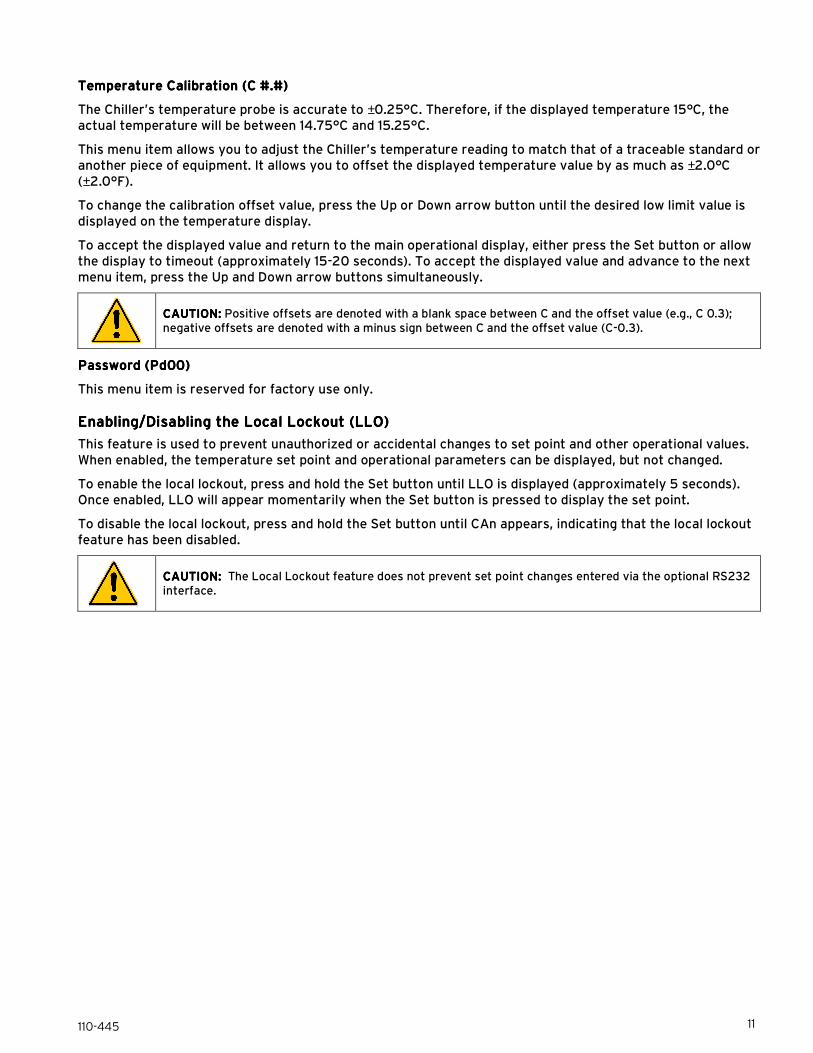
Temperature Temperature Temperature Temperature Calibration (CCalibration (CCalibration (CCalibration (C ####....####))))
The Chiller’s temperature probe is accurate to ±0.25°C. Therefore, if the displayed temperature 15°C, the actual temperature will be between 14.75°C and 15.25°C.
This menu item allows you to adjust the Chiller’s temperature reading to match that of a traceable standard or another piece of equipment. It allows you to offset the displayed temperature value by as much as ±2.0°C (±2.0°F).
To change the calibration offset value, press the Up or Down arrow button until the desired low limit value is displayed on the temperature display.
To accept the displayed value and return to the main operational display, either press the Set button or allow the display to timeout (approximately 15-20 seconds). To accept the displayed value and advance to the next menu item, press the Up and Down arrow buttons simultaneously.
CAUTION:CAUTION:CAUTION:CAUTION: Positive offsets are denoted with a blank space between C and the offset value (e.g., C 0.3); negative offsets are denoted with a minus sign between C and the offset value (C-0.3).
PasswordPasswordPasswordPassword (Pd00) (Pd00) (Pd00) (Pd00)
This menu item is reserved for factory use only.
Enabling/Disabling the Local LockoutEnabling/Disabling the Local LockoutEnabling/Disabling the Local LockoutEnabling/Disabling the Local Lockout (LLO) (LLO) (LLO) (LLO)
This feature is used to prevent unauthorized or accidental changes to set point and other operational values. When enabled, the temperature set point and operational parameters can be displayed, but not changed.
To enable the local lockout, press and hold the Set button until LLO is displayed (approximately 5 seconds). Once enabled, LLO will appear momentarily when the Set button is pressed to display the set point.
To disable the local lockout, press and hold the Set button until CAn appears, indicating that the local lockout feature has been disabled.
CAUTION:CAUTION:CAUTION:CAUTION: The Local Lockout feature does not prevent set point changes entered via the optional RS232 interface.

110-445 12
Display, Display, Display, Display, Error Error Error Error and Fault and Fault and Fault and Fault MessagesMessagesMessagesMessages
When certain conditions are detected, message codes flash on the display. Depending on the nature of the condition, power to various systems components is removed. When the condition is rectified, press the front panel Power button or turn power switch/circuit breaker Off then On to clear the fault or error.
Message CodeMessage CodeMessage CodeMessage Code DescriptionDescriptionDescriptionDescription AcAcAcAction Requiredtion Requiredtion Requiredtion Required
EHLEHLEHLEHL EEEE----HIHIHIHI
Error High Limit
Error — The set point temperature has been set higher than the high limit temperature.
Chiller Operation — Chiller continues normal operation; display alternates between EHL, E-HI and the fluid temperature.
Action — Decrease set point temperature or increase high limit temperature.
FHLFHLFHLFHL Fault High Limit
Fault — The fluid temperature has exceeded the high limit temperature for more than 25
seconds.
Chiller Operation — Normal operation stops, with heating and cooling turned off and the pump remaining on. FHL displayed continuously.
Action — Correct high fluid temperature problem or increase high limit temperature.
ELLELLELLELL EEEE----LOLOLOLO
Error Low Limit
Error — The set point temperature has been set lower than the low limit temperature.
Chiller Operation — Chiller continues normal operation; display alternates between ELL, E-LO and the fluid temperature.
Action — Increase set point temperature or decrease low limit temperature.
ELLELLELLELL Fault Low Limit
Fault — The fluid temperature has been below the low limit temperature for more than 25 seconds.
Chiller Operation — Normal operation stops, with heating and cooling turned off and the pump
remaining on. ELL displayed continuously.
Action — Correct low fluid temperature problem or decrease low limit temperature.
EFLEFLEFLEFL Fluid Low Error
Error — Fluid flow is low.
Chiller Operation — Chiller continues normal operation; display alternates between EFL and the
fluid temperature.
Action — Add fluid to reservoir; check lines for restrictions.
FFLFFLFFLFFL Fluid Flow Fault
Fault — The fluid flow has been low for more than 20 seconds.
Chiller Operation — Normal operation stops, with heating, cooling, and pump turned off. FFL
displayed continuously.
Action — Add fluid to reservoir; check lines for restrictions.
Ft3Ft3Ft3Ft3 Fault 3
Fault — One or all instrument settings are out of range.
Chiller Operation — Normal operation stops, with heating, cooling, and pump turned off. Ft3
displayed continuously.
Action — Contact manufacturer
FOtFOtFOtFOt Fault OTP
Fault — Heater over-temperature fault.
Chiller Operation — Normal operation stops, with heating, cooling, and pump turned off. FOt displayed continuously.
Action — Contact manufacturer.
Ft5Ft5Ft5Ft5 Fault 5
Fault — Heater Triac failure.
Chiller Operation — Normal operation stops, with heating, cooling, and pump turned off. Ft5 displayed continuously.
Action — Contact manufacturer.
Ft7Ft7Ft7Ft7 Temperature Probe Fault
Fault — The main temperature probe has failed.
Chiller Operation — Normal operation stops, with heating, cooling, and pump turned off. Ft7 displayed continuously.
Action — Contact manufacturer.

110-445 13
Routine Maintenance and TroubleshootingRoutine Maintenance and TroubleshootingRoutine Maintenance and TroubleshootingRoutine Maintenance and Troubleshooting
The Chiller is designed to require a minimum of periodic maintenance.
Magnetic Drive Centrifugal PumpMagnetic Drive Centrifugal PumpMagnetic Drive Centrifugal PumpMagnetic Drive Centrifugal Pump
When used under continuous operating conditions, this pump should be oiled every six (6) months with SAE 20 oil. The pump incorporates two oil ports for this purpose.
To access the pump:
1. Turn both power switches off and unplug the power cord.
2. Remove the two screws securing the left side panel (as viewed from the front) of the housing to the frame.
NOTE:NOTE:NOTE:NOTE: If your Chiller is equipped with a turbine pump, no pump maintenance is required.
Condenser, Air Vents, and Reusable FCondenser, Air Vents, and Reusable FCondenser, Air Vents, and Reusable FCondenser, Air Vents, and Reusable Filterilterilterilter
To keep the system operating at optimum cooling capacity, the condenser, the air vents, and reusable filter should be kept free of dust and dirt. They should be checked on a scheduled basis and cleaned as required.
To access the air filter, open the filter compartment door by placing your index finders in the cutouts on the sides of the compartment door (upper corners) and pulling towards you.
Remove the filter and remove accumulated dust and dirt. It may be cleaned by either vacuuming, blowing out with a clean air source, and/or washing with a mild detergent and water solution. If using a detergent/water solution, be sure to rinse and dry thoroughly before reinstalling.
Reusable air filter: Part number 750-758
Fluid LevelFluid LevelFluid LevelFluid Level
The fluid level gauge on the front panel of the Chiller should be periodically checked to determine if the fluid level needs to be topped off. Generally, fluid should be added whenever the level in the reservoir is below the “Full” mark.
Temperature Calibration Temperature Calibration Temperature Calibration Temperature Calibration
At times, there may be a minor temperature difference between the Chiller’s displayed temperature and the actual temperature as determined by a certified temperature measurement device. There may also be situations where you want the displayed temperature to match a particular value to have standardization between different instruments. These adjustments can be performed using the Chiller’s temperature calibration offset functions. See Normal Operation, Temperature Calibration (C #.#).
Filter compartment door access cutouts
(both sides of compartment door)
Washable air filter
110-445 14
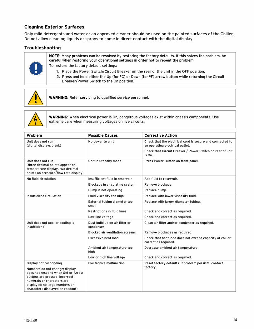
Cleaning Exterior Surfaces Cleaning Exterior Surfaces Cleaning Exterior Surfaces Cleaning Exterior Surfaces
Only mild detergents and water or an approved cleaner should be used on the painted surfaces of the Chiller. Do not allow cleaning liquids or sprays to come in direct contact with the digital display.
TroubleshootingTroubleshootingTroubleshootingTroubleshooting
NONONONOTE: TE: TE: TE: Many problems can be resolved by restoring the factory defaults. If this solves the problem, be careful when restoring your operational settings in order not to repeat the problem.
To restore the factory default settings:
1. Place the Power Switch/Circuit Breaker on the rear of the unit in the OFF position.
2. Press and hold either the Up (for °C) or Down (for °F) arrow button while returning the Circuit Breaker/Power Switch to the On position.
WARNING:WARNING:WARNING:WARNING: Refer servicing to qualified service personnel.
WARNING:WARNING:WARNING:WARNING: When electrical power is On, dangerous voltages exist within chassis components. Use extreme care when measuring voltages on live circuits.
ProblemProblemProblemProblem Possible CausesPossible CausesPossible CausesPossible Causes Corrective ActionCorrective ActionCorrective ActionCorrective Action
Unit does not run (digital displays blank)
No power to unit Check that the electrical cord is secure and connected to an operating electrical outlet.
Check that Circuit Breaker / Power Switch on rear of unit
is On.
Unit does not run (three decimal points appear on temperature display, two decimal
points on pressure/flow rate display)
Unit in Standby mode Press Power Button on front panel.
No fluid circulation Insufficient fluid in reservoir
Blockage in circulating system
Pump is not operating
Add fluid to reservoir.
Remove blockage.
Replace pump.
Insufficient circulation Fluid viscosity too high
External tubing diameter too small
Restrictions in fluid lines
Low line voltage
Replace with lower viscosity fluid.
Replace with larger diameter tubing.
Check and correct as required.
Check and correct as required.
Unit does not cool or cooling is insufficient
Dust build up on air filter or condenser
Blocked air ventilation screens
Excessive heat load
Ambient air temperature too high
Low or high line voltage
Clean air filter and/or condenser as required.
Remove blockages as required.
Check that heat load does not exceed capacity of chiller; correct as required.
Decrease ambient air temperature.
Check and correct as required.
Display not responding
Numbers do not change; display does not respond when Set or Arrow buttons are pressed; incorrect numerals or characters are displayed; no large numbers or
characters displayed on readout)
Electronics malfunction Reset factory defaults. If problem persists, contact factory.

110-445 15
5
10
15
20
25
30
35
40
0 5 10 15
Flow - lpm
Pre
ss
ure
- p
si
0
40
80
120
160
200
240
280
Pre
ss
ure
- k
Pa
Technical Information
Model LS51/LS53 60Hz Compact Chiller SpecificationsModel LS51/LS53 60Hz Compact Chiller SpecificationsModel LS51/LS53 60Hz Compact Chiller SpecificationsModel LS51/LS53 60Hz Compact Chiller Specifications
Performance 120/230V, 60HzPerformance 120/230V, 60HzPerformance 120/230V, 60HzPerformance 120/230V, 60Hz
Working temperature range 1 -20° to +40°C / -4° to +104°F
Operating temperature range 2 -20° to +60°C / -4° to +140°F
Temperature Stability ±0.1°C (±0.18°F)
Cooling capacity Ethylene Glycol & Water (50/50 mix)
Pump MX Centrifugal M1 Centrifugal TX Turbine
@ Watts BTU/Hr Watts BTU/Hr @ Watts BTU/Hr
-20°C -10°C 0°C
+10°C +20°C +30°C +40°C
260 475 750 1130 1290 1460 1610
888 1622 2561 3859 4406 4986 5498
230 435 680 1030 1160 1380 1550
785 1486 2322 3518 3962 4713 5294
-20°C -10°C 0°C
+10°C +20°C +30°C +40°C
150 345 540 790 900 1020 1140
512 1178 1844 2698 3074 3483 3893
1. The temperature that the chiller can reach without an external heating or cooling source.
2. The temperature range in which the chiller can control temperature, limited by electronics.
0
200
400
600
800
1000
1200
1400
1600
1800
-20 -10 0 10 20 30 40
Fluid Temperature - °C
Cooling C
apacity - W
atts Centrifugal Pump
Turbine Pump
Pump optionPump optionPump optionPump option MX MX MX MX ---- Centrifugal Centrifugal Centrifugal Centrifugal M1 M1 M1 M1 ---- Centrifugal Centrifugal Centrifugal Centrifugal TX TX TX TX ---- Turbine Turbine Turbine Turbine
Maximum Flow 13.2 lpm / 3.5 gpm 14.8 lpm / 3.9 gpm 9.8 lpm / 2.6 gpm
Maximum Pressure 14.5 psi / 0.99 bar 9 psi / 0.62 bar 43.4 psi / 2.99 bar
Maximum Head 10.2 m / 33.5 ft H2O 5.6 m / 18.5 ft H2O 26.75 m / 87.8 ft H2O
Specifications are subject to change. Performance data based on 120V or 230V, 60hz input power, 20°C ambient temperature and a 50/50 mix of Ethylene Glycol and distilled water as coolant.
TX
MX
M1
110-445 16
5
7
9
11
13
15
17
19
21
23
25
0 5 10 15
Flow - lpm
Pre
ssu
re -
psi
20
40
60
80
100
120
140
160
180
Pre
ss
ure
- k
Pa
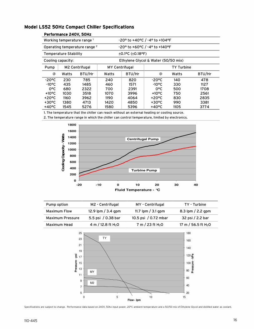
Model LS52 50Hz CompactModel LS52 50Hz CompactModel LS52 50Hz CompactModel LS52 50Hz Compact Chiller Specifications Chiller Specifications Chiller Specifications Chiller Specifications
Performance 240V, 50HzPerformance 240V, 50HzPerformance 240V, 50HzPerformance 240V, 50Hz
Working temperature range 1 -20° to +40°C / -4° to +104°F
Operating temperature range 2 -20° to +60°C / -4° to +140°F
Temperature Stability ±0.1°C (±0.18°F)
Cooling capacity: Ethylene Glycol & Water (50/50 mix)
Pump M2 Centrifugal MY Centrifugal TY Turbine
@ Watts BTU/Hr Watts BTU/Hr @ Watts BTU/Hr
-20°C -10°C 0°C
+10°C +20°C +30°C +40°C
230 435 680 1030 1160 1380 1545
785 1485 2322 3518 3962 4713 5276
240 460 700 1070 1190 1420 1580
820 1571 2391 3996 4064 4850 5396
-20°C -10°C 0°C
+10°C +20°C +30°C +40°C
140 330 500 750 830 990 1105
478 1127 1708 2561 2835 3381 3774
1. The temperature that the chiller can reach without an external heating or cooling source.
2. The temperature range in which the chiller can control temperature, limited by electronics.
0
200
400
600
800
1000
1200
1400
1600
1800
-20 -10 0 10 20 30 40
Fluid Temperature - °C
Cooling C
apacity - W
atts
Centrifugal Pump
Turbine Pump
Pump option M2 - Centrifugal MY - Centrifugal TY - Turbine
Maximum Flow 12.9 lpm / 3.4 gpm 11.7 lpm / 3.1 gpm 8.3 lpm / 2.2 gpm
Maximum Pressure 5.5 psi / 0.38 bar 10.5 psi / 0.72 mbar 32 psi / 2.2 bar
Maximum Head 4 m / 12.8 ft H2O 7 m / 23 ft H2O 17 m / 56.5 ft H2O
Specifications are subject to change. Performance data based on 240V, 50hz input power, 20°C ambient temperature and a 50/50 mix of Ethylene Glycol and distilled water as coolant.
TY
MY
M2

110-445 17
General Information & SpecificationsGeneral Information & SpecificationsGeneral Information & SpecificationsGeneral Information & Specifications
SafetySafetySafetySafety
Auto-restart on power failure Yes
Low flow alarm and power cutoff Yes
High temperature safety Yes
High temperature limit Yes (user adjustable)
Low temperature limit Yes (user adjustable)
ComplianceComplianceComplianceCompliance
CSA-US Yes
CE Yes
WEEE Compliant
RoHS Compliant
ConstructionConstructionConstructionConstruction
Outer case Epoxy powder coated steel
Wetted parts Brass, Copper, Stainless Steel, EPDM Rubber, Alcryn,
Nylon, PVC, and Polyethylene
Unit dimensions (L x W x H) 60.7 x 25.4 x 48.3 cm / 23.9 x 10 x 19 in.
Unit weight 46.3 kg / 102 lbs
Reservoir volume 2.65 L / 0.7 gal
Heat exchanger Stainless steel copper-brazed plate
Noise Rating (measured at .9 m from the unit)
53 dBA
Compressor Hermetic
Refrigerant type R-404a
ControllerControllerControllerController
Display type Digital, LED
Temperature stability ±0.1°C
Display resolution 0.1°
Temperature Units °C or °F
User calibration Temperature
SetupSetupSetupSetup
Recommended fluid(s) 50/50 mix of distilled water and ethylene glycol
Incompatible fluids Corrosive or flammable fluids; Deionized water package available
Ambient temperature operating range 5° to 35°C / 41° to 95°F
Maximum relative humidity 80% non-condensing
Operating power requirements 103 - 127V, 12A, 60Hz (LS51) 208 – 253V, 6A 60Hz (LS53)
216 – 264V, 6A, 50Hz (LS52)
Fluid inlet/outlet 0.5 inch female brass NPT
Recommended tubing I.D. 0.375 inch / 9.5 mm (minimum)
Specifications subject to change without notice.
Environmental Conditions Indoor use only Maximum Altitude: 2000 meter Operating Ambient: 5° to 35°C (41° to 95°F) Relative Humidity: 80%, non-condensing Installation Category: II Pollution Degree: 2

110-445 18
RS232RS232RS232RS232 Serial Communications Serial Communications Serial Communications Serial Communications (Optional) (Optional) (Optional) (Optional)
This option allows you to remotely control the Chiller and/or output temperature readings to an external recorder or other auxiliary device. The maximum communications distance for Chillers equipped with the RS232 option is 15 meters (50 feet).
Serial Connector — A 9-pin D-connector is provided on the back panel of the Chiller for RS232 data communication. A serial cable that uses only the following pins should be used to connect the Chiller to the computer: Pin #2 — data read (data from computer) Pin #3 — data transmit (data to computer) Pin #5 — Signal ground
RS232 Protocol — The Controller uses the following RS232 protocol: Data bits — 8 Parity — None Stop bits — 1 Flow control — None Baud rate — Selectable (Chiller and PC baud rates must match).
Communications Commands — Commands must be entered in the exact format shown. Do not send a [LF] (line feed) after the [CR] (carriage return). Be sure to follow character case exactly. A response followed by an exclamation point (!) indicates that a command was executed correctly. A question mark (?) indicates that the Chiller could not execute the command (either because it was in an improper format or the values were outside the allowable range). A response must be received from the Chiller before another command can be sent. All responses are terminated with a single [CR].
Command DescriptionCommand DescriptionCommand DescriptionCommand Description Command FormatCommand FormatCommand FormatCommand Format ValuesValuesValuesValues Return MessageReturn MessageReturn MessageReturn Message
Set Command Echo SEi[CR] Echo: i = 1 No Echo: i = 0
![CR]
Set On / Off SOi[CR] i = 1 to turn on i = 0 to turn off
![CR]
Set Set Point SSxxx[CR] x = ASCII digit ![CR]
Read Set Point Temperature RS[CR] +xx.x[CR] or -xx.x[CR]
Read Temperature RT[CR] +xx.x[CR] or -xx.x[CR]]
Read Temperature Units RU[CR] C or F C[CR] or F[CR]
Read Status RW[CR] 1 = Run 0 = Standby 1[CR] or 0[CR]
Read Compressor Discharge Temperature (°C) RUT[CR] xxx.x[CR]
Read fault status RF[CR]
00 = System OK Faults
![CR]
Read Evaporator Inlet Temperature (°C) REI[CR] xxx.x[CR]
Read Evaporator outlet temperature (°C) REO[CR] xxx.x[CR]
Output continuous data stream, one set per second
Set on/off RDi[CR]
i = 1 to turn on
i = 0 to turn off ![CR]
RD command results in a continuous data stream. Headers are:
Min.sec, software version, temperature units, temperature setpoint, fluid temperature, remote probe temperature, not used, compressor discharge temperature, evaporator inlet temperature, evaporator outlet temperature, heat %, cool %, fan %. Temperatures are always in degrees Celsius.

110-445 19
Equipment Disposal (WEEE Directive)Equipment Disposal (WEEE Directive)Equipment Disposal (WEEE Directive)Equipment Disposal (WEEE Directive)
or
This equipment is marked with the crossed out wheeled bin symbol to indicate it is covered by the Waste Electrical and Electronic Equipment (WEEE) Directive and is not to be disposed of as unsorted municipal waste. Any products marked with this symbol must be collected separately, according to the regulatory Any products marked with this symbol must be collected separately, according to the regulatory Any products marked with this symbol must be collected separately, according to the regulatory Any products marked with this symbol must be collected separately, according to the regulatory guidelines in your area.guidelines in your area.guidelines in your area.guidelines in your area.
It is your responsibility to correctly dispose of this equipment at lifecycle-end by handing it over to an authorized facility for separate collection and recycling. It is also your responsibility to decontaminate the equipment in case of biological, chemical and/or radiological contamination, so as to protect the persons involved in the disposal and recycling of the equipment from health hazards. By doing so, you will help to conserve natural and environmental resources and you will ensure that your equipment is recycled in a manner that protects human health.
Requirements for waste collection, reuse, recycling, and recovery programs vary by regulatory authority at your location. Contact your local responsible body (e.g., your laboratory manager) or authorized representative for information regarding applicable disposal regulations.
Service and Technical SupportService and Technical SupportService and Technical SupportService and Technical Support
If you have followed the troubleshooting steps and your Recirculating Chiller fails to operate properly, contact the supplier from whom the unit was purchased. Have the following information available for the customer service person:
• Model, Serial Number, and Voltage (from back panel)
• Date of purchase and your purchase order number
• Suppliers' order number or invoice number
• A summary of your problem

110-445 20
Replacement Parts and AccessoriesReplacement Parts and AccessoriesReplacement Parts and AccessoriesReplacement Parts and Accessories
DescriptionDescriptionDescriptionDescription Part NumberPart NumberPart NumberPart Number
Reservoir Cap 300-460
Reservoir Spill Cup 300-575
Centrifugal Pump, M1 (120 V, 60 Hz) 525-782
Centrifugal Pump, M2 (230/240 V, 50/60 Hz) 525-783
Centrifugal Pump, MX (120 V, 60 Hz) 525-784
Centrifugal Pump, MY (230/240 V, 50/60 Hz) 525-785
Turbine Pump, TX (120 V, 60 Hz) 525-780
Turbine Pump, TY (230/240 V, 50/60 Hz) 525-781
Condenser 750-763
Compressor (120 V, 60 Hz) 750-369
Compressor (230 V, 60 Hz) 750-769
Compressor (240 V, 50 Hz) 750-370
Fan Motor (60 Hz) 215-642
Fan Motor (50 Hz) 215-643
Circuit Breaker (50/60 Hz) 215-330
Buna N Tubing, ½” (13 mm); 1 m (39”) length 060308
Viton Tubing, ½” (13 mm); 1 m (39”) length 060316
Viton Tubing, 3/8” (10 mm); 1 m (39”) length 060319
Insulation for all ½” (13 mm) tubing; 1 m (39”) length 060311
Tube Clamp for ½” (13 mm), 5/8” (16 mm), and ¾” (18 mm) O.D. tubing, 1 each 400-898
Fitting, ½” male NPT to 3/8” (9.5 mm), hose barb, brass, straight 776-196
Fitting, ½” male NPT to 3/8” (9.5 mm), hose barb, brass, elbow 775-047
Fitting, ½” male NPT to 5/8” (16 mm), hose barb, nylon, straight 300-131
Fitting, ½” male NPT to ½” (13 mm), hose barb, nylon, straight 300-096
Fitting, ½” male NPT to ¾” (19 mm), hose barb, nylon, straight 776-197
Fitting, ½” male NPT to M16x1 13 mm (½”), brass, straight 775-048
Manifold Kit, 2 ports with shutoffs 510-665
Manifold Kit, 4 ports with shutoffs 510-664
Air Filter 750-758
Operator’s Manual 110-445

110-445 21
PolyScience Chiller FluidsPolyScience Chiller FluidsPolyScience Chiller FluidsPolyScience Chiller Fluids
Circulating Bath FluidsCirculating Bath FluidsCirculating Bath FluidsCirculating Bath Fluids QuantityQuantityQuantityQuantity Part NumberPart NumberPart NumberPart Number
polyclean Algaecide 8 oz / 236 ml 004-300040
polyclean Algaecide Twelve 8 oz / 236 ml bottles 004-300041
polycool EG -25 (ethylene glycol) 1 gal / 4.5 liter 060340
polycool PG -20 (propylene glycol) 1 gal / 4.5 liter 060320
polycool HC -50 (water-based heat transfer fluid) 1 gal / 4.5 liter 060330
polycool MIX -25 (50/50 blend polycool EG -25 / H2O plus polyclean algaecide)
Five 0.5 gal / 2.27 liter bottles 004-300060
WarrantyWarrantyWarrantyWarranty
The manufacturer agrees to correct for the original user of the product, either by repair (using new or refurbished parts), or at the manufacturer’s election, by replacement (with a new or refurbished product), any defects in material or workmanship which develop during the warranty period. The standard warranty is twenty-four (24) months after delivery of the product. In the event of replacement, the replacement unit will be warranted for the remainder of the original warranty period or ninety (90) days, whichever is longer. For purposes of this limited warranty, “refurbished” means a product or part that has been returned to its original specifications. In the event of a defect, these are your exclusive remedies.
If the product should require service, contact the manufacturer’s/supplier’s office for instructions. When return of the product is necessary, a return authorization number is assigned and the product should be shipped, transportation charges pre-paid, in either its original packaging or packaging affording an equal degree of protection to the indicated service center. To insure prompt handling, the return authorization number must be placed on the outside of the package. A detailed explanation of the defect should be enclosed with the item.
The warranty shall not apply if the defect or malfunction was caused by accident, neglect, unreasonable use, improper service, acts of God, modification by any party other than the manufacturer, or other causes not arising out of defects in material or workmanship.
EXCLUSION OF IMPLIED WARRANTIES.EXCLUSION OF IMPLIED WARRANTIES.EXCLUSION OF IMPLIED WARRANTIES.EXCLUSION OF IMPLIED WARRANTIES. THERE ARE NO WARRANTIES, EXPRESSED OR IMPLIED, INCLUDING, BUT NOT LIMITED TO, THOSE OF MERCHANTABILITY OR FITNESS FOR A PARTICULAR PURPOSE WHICH EXTEND BEYOND THE DESCRIPTION AND PERIOD AS STATED IN THE OPERATOR’S MANUAL INCLUDED WITH EACH PRODUCT.
LIMITATION ON DAMAGES.LIMITATION ON DAMAGES.LIMITATION ON DAMAGES.LIMITATION ON DAMAGES. THE MANUFACTURER’S SOLE OBLIGATION UNDER THE WARRANTY IS LIMITED TO THE REPAIR OR REPLACEMENT OF A DEFECTIVE PRODUCT AND THE MANUFACTURER SHALL NOT, IN ANY EVENT, BE LIABLE FOR ANY INCIDENTAL OR CONSEQUENTIAL DAMAGES OF ANY KIND RESULTING FROM USE OR POSSESSION OF THIS PRODUCT.
Some states do not allow: (A) limitations on how long an implied warranty lasts; or (B) the exclusion or limitation of incidental or consequential damages, so the above limitations or exclusions may not apply to you. This warranty gives you specific legal rights and you may have other rights that vary from state to state.
Manufactured by:
PolyScience
6600 W. Touhy Avenue Niles, IL 60714 U.S.A. 1-800-229-7569 \ 1-847-647-0611
www.polyscience.com