Embed Size (px)
Citation preview

LS L
OA
DE
RO
PE
RA
TO
R M
AN
UA
L
LS LOADER
OPERATOR MANUAL
PO Box 70, Battleboro, NC 27809
Tel : 252-984-0700
Fax : 252-984-0701
www.lstractor.com
www.lstractorusa.com
INNOVATIVETECHNOLOGY
PARTNER
LB
1101/L
B1102
LB1100 SERIES
P/NO BT013-ME000-11
TRACTOR Model• LB1101 : S3010• LB1102 : G3033/G3033H, G3038/G3038H
LS BACK-HOE
LS B
AC
K-H
OE

WARRANTY CONDITIONS
Warranty Coverage :
Warranty Provisions :
− Compensation is not paid for physical harm, deadlock, resulting damages or other losses.
Right To Make Design and Product Changes :
− The purchaser shall at all times in the operation of any LS Mtron Product, use those brandsand grades of lubricating oils, lubricants or fuel and spare parts officially approved by LS Mtron.
− The LS Mtron Backhoes shall have been used in accordance with the procedures specified inthe Operator's Manual. This Warranty does not extend to damage resulting from misapplication,abuse, misuse, failure to preform maintenance, negligence, fire, accidents or changes or faultymounting carried out by the Purchaser. When making a Warranty exchange of parts, thePurchaser shall compensate LS Mtron for the time that the parts have been used if they havebeen exposed to extreme wear.
There are no warranties beyond those which expressly appear herein. Any implied warranty ofmerchantability or fitness for a particular purpose is specifically exclude here from.
LS Mtron reserves the right to make changes in the design and other changes in its LS MtronProducts at any time without incurring any obligation with respect to any product previouslyordered, sold or shipped.
− Temporary repairs or additional costs due to the work being performed after normal workinghours will not be compensated.
− The above warranty is in lieu of all other warranties on LS Mtron's behalf and neither partyassumes any other liability in connection with LS Mtron's Products.
− To obtain warranty service, the Purchaser must (1) report the product defect to an authorizedLS Mtron dealer and request repair within the applicable warranty term and (2) present evidenceof purchase.
− The Warranty shall be void if the LS Mtron Backhoe has been altered or repaired outside of aLS Mtron dealership or travel of dealer personnel to customer location for Warranty repair. Thecustomer shall also pay any premium for overtime labor requested by the customer.
LS Mtron's liability under this warranty is subject to the observance by the Purchaser of thefollowing provisions:
It is further understood and agreed that the defect should be immediately reported to the SellingDealer. The Selling Dealer will generally perform Warranty repairs or replacements and thePurchaser shall deliver the LS Mtron Backhoe to the Dealer's place of business or repair.
The obligation of LS Mtron to the Purchaser under this Warranty is limited to the repair orreplacement of defective parts by an authorized LS Mtron dealer. Repair or replacement inaccordance with this Warranty shall constitute fulfillment of all liabilities of LS Mtron and theSelling Dealer in respect to LS Mtron Backhoe.
LS Mtron Tractor Division, herein referred to as LS Mtron, undertakes to replace or repair any partof a LS Mtron Backhoe where damage has been proven to be caused by defects in material orworkmanship.
This Warranty is valid for a period of 1 year from the date of the original retail sale. Partsreplaced or repaired under the terms of this Warranty are guaranteed only until the originalwarranty expires. Warranty only applies to the original purchaser.
- 1 -

PLEASE NOTE :
Make sure all potential operators of the this equipment review this manual and all safetymessages contained within.
This safety symbol indicates important safety messages in this manual. When you seethis symbol, carefully read the message that follows and be alert to the possibility ofpersonal injury or death.
- 2 -

Table of Contents
Safety Precautions 4
Safety Decals 6
Backhoe Specifications 9
Introduction 10
Tractor Preparation 11
Backhoe Operation 12
Backhoe Removal 16
Backhoe Mounting 17
Lubrication and Maintenance 19
Trouble Shooting 21
Hydraulic System Schematic 25
Torque Tightening Chart 26
Parts IIlustrations 27
General Information 27Hose Kit - G3033/G3033H, G3038/G30380H 28 - S3010 29 - XG3025 30 - XG3032/XG3032H, XG3037/XG3037H 31Subframe Assembly - G3033/G3033H, G3038/G30380H 34 - S3010 35 - XG3000series, XG3100series 36 - XG3025 37Bucket, Dipperstick Assembly 38Boom Assembly 40Swing Frame Assembly 41Mainframe Assembly 42Seat, Control Assembly(HANIL) 44Seat, Control Assembly(WALVOIL) 46Hose Fitting Assembly(HANIL) 48Hose Fitting Assembly(WALVOIL) 50Bucket Cylinder Assembly 52Dipperstick Cylinder Assembly 53Boom Cylinder Assembly 54Swing Cylinder Assembly 55Stabilizer Cylinder Assembly-LH 56Stabilizer Cylinder Assembly-RH 57Control Valve Assembly-HANIL AV 80/6 58Control Valve Assembly-WALVOIL SD6/6 60Decals 62
- 3 -
SAFETY
Understand that your safety and the safety ofother persons is measured by how you serviceand operate this backhoe. Know the positionand operations of all controls before you theyto operate. Make sure you check all controlsin all safe area before starting.
Read this manual completely and thoroughlyand make sure you understand all controls. Allequipment has a limit. Make sure you are awareof the stability and load characteristics of thisbackhoe before you begin operation.
The safety information given in this manualdoes not replace any safety codes, insuranceneeds, federal, state and local laws. Makesure your machine has the correct equipmentrequired by your local laws and regulations.
To prevent personal injury, relieve all pressurebefore disconnecting fluid lines.
When using remote hydraulic tractor valves onsome tractors, the backhoe lift and dumpcylinders will continue moving unless thecontrol levers are manually returned to neutral,or until relief pressure is reached at the endsof piston strokes. Observe the bucketmovement and maintain control with thecontrol levers.
Before applying hydraulic pressure, make sureall hydraulic connections are tight andcomponents are in good condition.
Stay off of slopes too steep for safe operation.Shift down before you start up or down a hillwith a heavy load. Avoid "free wheeling"
Equip your tractor with a ROPS cab or framefor your protection. See your tractor operator'smanual for correct seat belt usage.
Travel speed should be such that completecontrol and machine stability is maintained at alltimes. Where possible, avoid operation nearditches, embankments and holes. Reducespeed when turning, crossing slopes, and onrough, slick or muddy surfaces.
Operate controls only when seated in theoperator's seat.
A frequent cause of personal injury or death ispersons falling off and being run over. Do notpermit others to ride on your tractor. Only oneperson, the operator, should be on themachine when it is in operation.
Never use your hand to check for suspectedleaks under pressure. Use a piece of cardbordor wood for this purpose. Escaping hydraulic oilor diesel fuel leaking under pressure can havehave sufficient force to penetrate the skin andcause infection or other injured by leaking fluid,seek medical attention immediately.
Before leaving the tractor, stop the engine,put all controls in neutral, engage the parkingbrake and remove the key from the ignition.
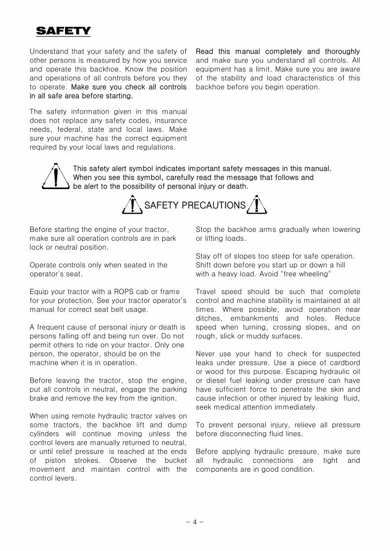
This safety alert symbol indicates important safety messages in this manual. When you see this symbol, carefully read the message that follows and be alert to the possibility of personal injury or death.
SAFETY PRECAUTIONS
Before starting the engine of your tractor,make sure all operation controls are in parklock or neutral position.
Stop the backhoe arms gradually when loweringor lifting loads.
- 4 -

SAFETY
Contact with overhead power lines can causesevere electrical burn or death fromelectrocution.Make sure there is enough clearance betweenraised equipment and overhead power lines.
Make sure all parked backhoe on stands are ona hard level surface with all safety devicesengaged to prevent backhoe from falling andbeing damaged or injuring someone.
Do not stand, walk or work under a raisedbackhoe or attachment unless it is securelyblocked or held in position. Accidentalmovement of a control lever or leak in thehydraulic system could cause the backhoe todrop, or attachment to dump, causing severeinjury.
When using a backhoe, be alert of bucket,boom and arm position at all times.Add recommended rear tire liquid weight or
rear wheel weights for increased stability.
A backhoe attachment should be transportedin a low position at slow ground speeds. Maketurns slowly and use the tractor brakescautiously. A loaded attachment in the raisedposition alters the center of gravity location ofthe machine and increases the possibility ofmishaps.
- 5 -
SAFETY DECALS
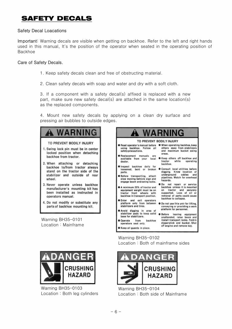
Safety Decal Loacations
Care of Safety Decals.
1. Keep safety decals clean and free of obstructing material.
2. Clean safety decals with soap and water and dry with a soft cloth.
Important: Warning decals are visible when getting on backhoe. Refer to the left and right handsused in this manual, It's the position of the operator when seated in the operating position ofBackhoe
3. If a component with a safety decal(s) affixed is replaced with a newpart, make sure new safety decal(s) are attached in the same location(s)as the replaced components.
4. Mount new safety decals by applying on a clean dry surface andpressing air bubbles to outside edges.
Warning BH35-0101Location : Mainframe
Warning BH35-0102Location : Both of mainframe sides
Warning BH35-0103Location : Both leg cylinders
Warning BH35-0104Location : Both side of Mainframe
- 6 -
SAFETY DECALS
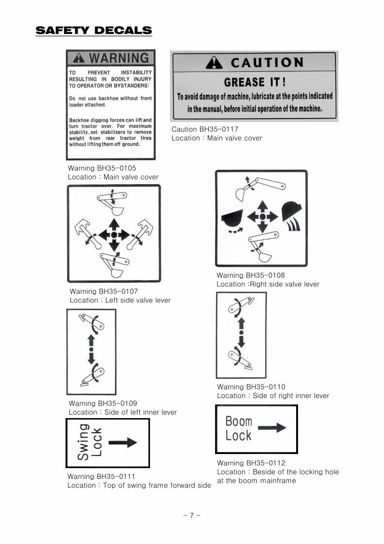
Warning BH35-0105Location : Main valve cover
Warning BH35-0107Location : Left side valve lever
Warning BH35-0109Location : Side of left inner lever
Warning BH35-0111Location : Top of swing frame forward side
Warning BH35-0108Location :Right side valve lever
Warning BH35-0110Location : Side of right inner lever
Warning BH35-0112Location : Beside of the locking holeat the boom mainframe
Caution BH35-0117Location : Main valve cover
- 7 -

SAFETY DECALS
Loader Series 3101E-00112Location : Boom side
Name Plate 3104E-00010Location : Both side of Valve Room
- 8 -

BACKHOE SPECIFICATIONS
Backhoe Model : LB1100Tractor Model : S3010, G3033/G3033H, G3038/G3038H, XG3000series, XG3100series, XG3025
A. Digging Deth (two foot flat bottom) 1,940 mm 76.3 "B. Reach from center line of Swing Pivot 2,875 mm 113.1 "C. Loading Height (bucket at 60°) 1,615 mm 63.6 "D. Maximum Leveling Angle 10 ° 10 °E. Swing Arc 180 ° 180 °F. Transport Height (maximum) 1,960 mm 77.2 "G. Transport Overhang 1,105 mm 43.5 "H. Bucket Rotation 180 ° 180 °I. Stabilizer Spread (down position) 1,745 mm 68.7 "J. Stabilizer Spread (up position) 1,180 mm 46.4 "K. Angle of Departure 21 ° 21 °
Shipping Weight - Backhoe(without bucket) 470 ㎏ 1,036 lbsBucket Digging Force 1,278 ㎏ 2,817 lbsDipperstick Digging Force 793 ㎏ 1,748 lbsOperating Pressure 170 bar 2,466 psi
Specifications may vary depending on tractor model, tire size and bucket used.
Specifications and design aresubject to change without prior
mm inch mm inch mm inch mm inchBoom 70 2.756 586 23.071 384 15.118 40 1.575Bucket 60 2.362 535 21.063 299 11.772 35 1.378
Dipperstick 60 2.362 524 20.630 303 11.929 35 1.378Swing 60 2.362 398 15.669 223 8.780 35 1.378
Stabilizer 60 2.362 446 17.559 262 10.315 35 1.378
Buckets Bucket 9" Bucket
12" Bucket16" Bucket18" Bucket24" Bucket36" Bucket 6 2.78 cu. ft. 4.00 cu. ft. 114 lbs.
5 2.11 cu. ft. 2.82 cu. ft. 94 lbs.
46 lbs.
Rod DIACylinder
Shipping Weight
CylindersBore DIA Retracted Length Stroke
2.02 cu. ft.1.38 cu. ft.
Heaped Capacity
33
Teeth Q'TY Struck Capacity3 0.73 cu. ft. 0.87 cu. ft.
70 lbs.
1.24 cu. ft. 56 lbs.1.76 cu. ft. 64 lbs.
4
1.01 cu. ft.
1.56 cu. ft.
C
G
F
B J
A
E
2'
K
I
D
- 9 -

INTRODUCTION
Important:
Warranty Registration
Serial Number and Location
Backhoe Components
"Right" and "Left" as used throughout thismanual are determined by facing the directionthe machine will travel when in use.
Illustrations used in this manual may not showall safety equipment that is recommended toensure safe operation of tractor and backhoe.Refer to the Safety Precautions section of thismanual for information concerning safety.consult your dealer for further information.
The Delivery and Warranty Registration formsmust be filled out and signed to validate yourwarranty protection. The items on the formunder "I hereby Acknowledge" should be readand understood. The terms and conditions ofthe warranty on this machine are specified inthe front of this manual.
The purpose of this manual is to assist you inmaintaining and operating your backhoe. Readit carefully, it furnishes information andinstructions that will help you achieve years ofdependable performance. Some informationmay be general in nature due to unknown andvarying conditions. However, throughexperience and these instructions, you shouldbe able to develop operating proceduressuitable to your particular situation.
The photos, illustrations and data used in thismanual are current at the time of printing, butdue to possible in-line production changes,your machine may vary slightly in detail. Themanufacturer reserves the right to redesign themachine as may be necessary withoutnotification.
The serial number is important informationabout the machine and it may be necessary toknow it before obtaining the correctreplacement part. The serial number is locatedon the front of valve cover. The serial numbershould be recorded on the Delivery andRegistration form and also below for yourreference.
Terms for backhoe components have somevariations throughout the industry.
1
2
3
4
5
7
8
9
10
11
12
6Backhoe Serial Number Information
Date Purchased
Backhoe Serial Number
Subframe Serial Number
Dealer Name and Telephone Number
1 Bucket2 Bucket Cylinder3 Dipperstick Cylinder4 Boom Cylinder5 Console6 Stabilizer7 Swing Cylinder8 Boom9 Dipperstick10 Stabilizer Cylinder11 Swing Frame12 Main Frame
- 10 -
TRACTOR PREPARATION
CAUTION: Tractor Hydraulic System
CAUTION:
ROPS System
CAUTION:The tractor/backhoe must only be operated with all safety equipment properly installed.
Tire Inflation Wheel Tread Settings
Do not exceed the manufacturer's ratingfor maximum gross vehicle weight. Referto Operator's Manual or ROPS serialplate provided with tractor.
Rear tires must be maintained at equal pressurewithin the recommended tire inflation range.Unequal rear tire inflation can prevent backhoeattachment from contacting the ground acrossits full width.
Adhere to recommendation in your TractorOperator's Manual concerning hydraulic fluidand filter specifications, and change intervals.
Tractor operation in a backhoe applicationsignificantly increase demands on the tractorHydraulic System. Check the tractor Hydraulicsystem fluid level daily. Refer to your tractorOperator's Manual maintenance section forinstructions regarding tractor hydraulic systemmaintenance.Certain specific conditions may not
permit safe use of backhoe at backhoerating or may require more carefulrestricted operation at the rated load.
The tractor must be equipped with an approvedROPS System to ensure adequate operator'sprotection.
Front tires must be maintained at the maximumrecommended inflation to maintain normal tireprofile with the added weight ofbackhoe/material.
Tractor front wheel tread setting must berestricted to wheel tread spacingrecommended in the tractor Operator'sManual.
- 11 -

BACKHOE OPERATION
CAUTION:
Precautionary Notes
We urge you to follow this advice:1. Read and understand this manual as well as the Tractor Operator's Manual.2. Remember and observe the Safety Precautions brought to your attention in this manual, the tractor manual and on the machinery itself.3. Use good common sense in the everyday operation of this unit. Safety recommendations can never be all- inclusive and you are responsible for watching out for and avoiding unsafe conditions.4. Never exceed the limits of a piece of machinery. If its ability to do a job or to do so safely is in question, don't try it.5. Don't hurry the learning process or take the unit for granted. Ease into it and become familiar with your new backhoe and tractor.
CAUTION: When lowering a heavy load,ease it downward slowly. Never drop a
Important:
CAUTION: Before disconnecting hydrauliclines, relieve all hydraulic pressure.
Important:
CAUTION: Do not operate the backhoe ifImportant: the fittings are leaking or if the hoses are
Position vehicle so that the backhoe is as nearto the pile as possible and in such a direction asto minimize the amount of tractor turningrequired to dump.
Keep the unit clean and perform regular service.Observe safety messages whenever cleaning,servicing, or lubricating.
Practice quickly turning off the engine orstopping the backhoe immediately in case ofan emergency situation.
Do not operate while the rear tractor wheelsare off the ground by stabilizer. It isdangerous to operate the backhoe while rearwheels are off the ground.
- Read and understand this manual to avoid accidents.
The tractor/backhoe should only be operatedwith all safety equipment properly installed.Keep assistants or bystanders a safe distancefrom the equipment operating area.
- Check below items before operating for your safety.
Use tractor engine speed that your experiencepermits. At first set PTO RPM of the tractor toslow.Do not use the boom, dipperstick, swing andstabilizers to lift, push or pull objects. Useonly to maneuver and operate the bucket.
Escaping hydraulic oil under pressure can havesufficient force to penetrate the skin causingserious personal injury. If injured by escapinghydraulic oil seek medical attention immediately.
loaded attachment and "catch it hydraulically".Stopping a load after it has gained downwardmomentum places undue strain on the unit andmay cause unnecessary damage to the backhoeor tractor or even worse, personal injury.
damaged. A sudden line burst would cause themainframe to drop suddenly, causing damageto the tractor or backhoe or injury to personnel.
- Check the hydraulic fitting lines to be correct and set tightly.- Maintain and repair (if it is needed) the parts or assemblies, check bolts and pins to be sure they are positioned tightly.- Check tractor with the tractor operator's manual that it can prepared for operating.- Warm up and operate the tractor and backhoe carefully. Purge any air in the hydraulic lines and cylinders by fully cycling all cylinders several times.- Check hydraulic level in the tank. It should be full (Refer to the Tractor Operator's Manual).- Do not operate the hydraulics when not seated in the backhoe operator's seat.
- Do not allow riders other than the operator to be on the tractor while operating.
- Keep all assistants out of area of operation.- Do not operate rapidly.
- 12 -

BACKHOE OPERATION
Initial Backhoe Operation
CAUTION: Cold Weather Operation
CAUTION:
Left and Right stabilizer controls
Before operating the backhoe, fully raise andlower the boom, arm, swing and stabilizerstwo or three times. Then raise the bucketabove the ground and cycle the bucketcylinders three times. Lower the bucket to theground. Check the tractor hydraulic oil andthe correct oil level.
Before leaving the machine, stop the engine,remove the key, place all controls in neutral,and either set the parking brake or placetractor in park as equipped.
Also, lock the swing and boom while tractor ismoving and storing for an extended period oftime.
Always keep cylinders in a retracted positionwhen the backhoe is not in use to guard againstrust and contamination which may causedamage to the cylinder rods or hydraulic system.
For smooth operation in cold weather, let thetractor warm up. Slowly cycle all of the cylindersseveral times to warm the oil in the hydraulicsystem. The backhoe may operate erraticallyuntil the hydraulic oil has warmed to operatingtemperatures.
Operate controls only when seated in the operator's seat.
Push the left hand inner control lever, left stabilizer lowers. And pull up the lever, left stabilizerraises.
Bucket/Crowd
Boom/Swing
Left Stabilizer
Right Stabilizer
Decal forLeft Stabilizer
Decal forRight Stabilizer
- 13 -
BACKHOE OPERATION
Do not dig near the stabilizers to avoid possible accident.
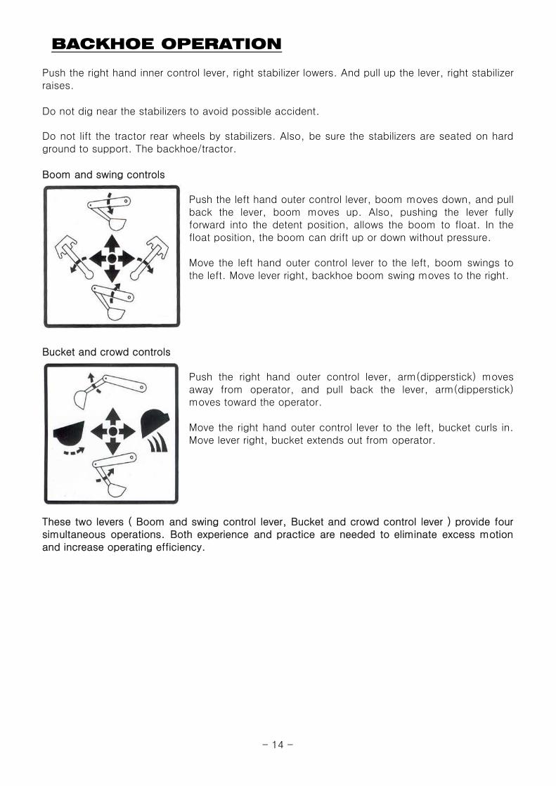
Boom and swing controls
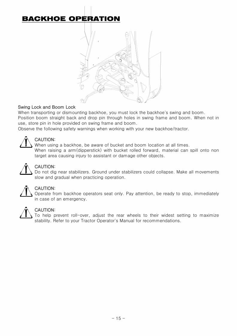
Bucket and crowd controls
Push the right hand inner control lever, right stabilizer lowers. And pull up the lever, right stabilizerraises.
Do not lift the tractor rear wheels by stabilizers. Also, be sure the stabilizers are seated on hardground to support. The backhoe/tractor.
Push the left hand outer control lever, boom moves down, and pullback the lever, boom moves up. Also, pushing the lever fullyforward into the detent position, allows the boom to float. In thefloat position, the boom can drift up or down without pressure.
Move the left hand outer control lever to the left, boom swings tothe left. Move lever right, backhoe boom swing moves to the right.
Push the right hand outer control lever, arm(dipperstick) movesaway from operator, and pull back the lever, arm(dipperstick)moves toward the operator.
Move the right hand outer control lever to the left, bucket curls in.Move lever right, bucket extends out from operator.
These two levers ( Boom and swing control lever, Bucket and crowd control lever ) provide foursimultaneous operations. Both experience and practice are needed to eliminate excess motionand increase operating efficiency.
- 14 -
BACKHOE OPERATION
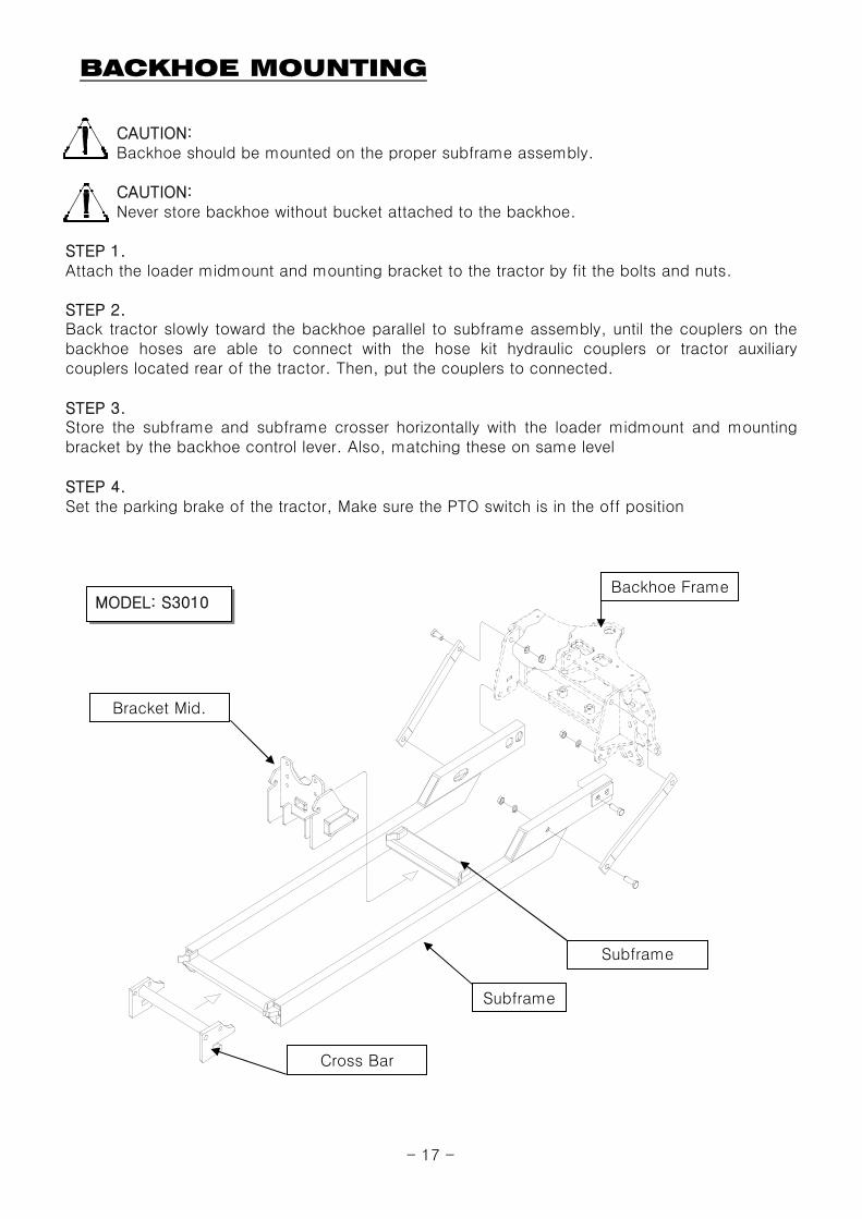
Swing Lock and Boom LockWhen transporting or dismounting backhoe, you must lock the backhoe's swing and boom.
Observe the following safety warnings when working with your new backhoe/tractor.
CAUTION: When using a backhoe, be aware of bucket and boom location at all times.
CAUTION:
CAUTION:
CAUTION:
When raising a arm(dipperstick) with bucket rolled forward, material can spill onto nontarget area causing injury to assistant or damage other objects.
Do not dig near stabilizers. Ground under stabilizers could collapse. Make all movementsslow and gradual when practicing operation.
Operate from backhoe operators seat only. Pay attention, be ready to stop, immediatelyin case of an emergency.
Position boom straight back and drop pin through holes in swing frame and boom. When not inuse, store pin in hole provided on swing frame and boom.
To help prevent roll-over, adjust the rear wheels to their widest setting to maximizestability. Refer to your Tractor Operator's Manual for recommendations.
- 15 -

BACKHOE REMOVAL
CAUTION: Move the backhoe to flat, firm and wide place to remove the equipment.
CAUTION:
WARNING: Use other lifting equipment to remove when the backhoe has damage.
STEP 1.Move the tractor to backhoe storage place.
STEP 2.
STEP 3.Center the boom and then lock the swing with lock pin.
STEP 4.
STEP 5.Remove pins that secure the backhoe. Subframe in the mounting brackets on the tractor.
STEP 6.
STEP 7.Move the tractor forward slowly until the backhoe subframe disengages of the mounting brackets.
STEP 8.
STEP 9.
CAUTION:
CAUTION: Be careful to avoid injury during removal of the backhoe.
CAUTION:
Turn off the tractor engine. Relieve hydraulic pressure by actuating all the control levers in eachdirection, then disconnect the backhoe hose couplers from the tractor hydraulic couplers.
Remove the backhoe on firm level ground. Also, Do not allow the other person in the area.
The hydraulic oil is dangerous for skin or eyes. Wash the skin and seek medical service if itis necessary.
Do not allow to be removed without bucket and stabilizers. Also, Dump the remainingmaterial from the bucket to empty.
Use the inner two levers to lower the stabilizers until they contact to the ground. Use the boomand dipperstick control lever to raise the boom & dipperstick completely.
Using the control levers, position the dipperstick vertically, curl the bucket until its bottom is levelwith the ground, and lower the boom until bottom of the bucket rests on the ground.
Using both the stabilizer and boom controls, set the backhoe subframe horizontally to relieve theweight of the backhoe from the mounting brackets of the tractor.
Lower the backhoe mainframe to the ground by raising stabilizers and boom. Use the wood plateor block if necessary.
- 16 -
BACKHOE MOUNTING
CAUTION:Backhoe should be mounted on the proper subframe assembly.
CAUTION:Never store backhoe without bucket attached to the backhoe.
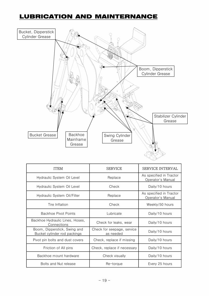
STEP 1.Attach the loader midmount and mounting bracket to the tractor by fit the bolts and nuts.
STEP 2.
STEP 3.
STEP 4.Set the parking brake of the tractor, Make sure the PTO switch is in the off position
Back tractor slowly toward the backhoe parallel to subframe assembly, until the couplers on thebackhoe hoses are able to connect with the hose kit hydraulic couplers or tractor auxiliarycouplers located rear of the tractor. Then, put the couplers to connected.
Store the subframe and subframe crosser horizontally with the loader midmount and mountingbracket by the backhoe control lever. Also, matching these on same level
Cross Bar
Bracket Mid.
Subframe
Subframe
MODEL: S3010Backhoe Frame
- 17 -

BACKHOE MOUNTING
CAUTION:This is the Backhoe's Operator's manual for Safety Precautions and Tractor Preparations.
STEP 5.
STEP 6.
STEP 7.Install the Mounting Bracket Pins into the holes. Raise the boom and stabilizers from the ground.
Move the tractor to put the subframe front side into the loader midmount slowly. Set the subframecrosser parallel to the mounting bracket by using the backhoe control levers to lower thestabilizers and boom to raise the subframe.
Release the parking brake of tractor, move the tractor rearward very carefully until the subframe isfully engaged in both mounting devices on the tractor.
Cross Bar
Bracket Mid.
Subframe
Subframe
MODEL: G3033/G3033H, G3038/G3038H XG3000series, XG3100series, XG3025
Backhoe Frame
- 18 -
LUBRICATION AND MAINTERNANCE
Bucket, DipperstickCylinder Grease
Bucket Grease
Boom, DipperstickCylinder Grease
Stabilizer CylinderGrease
Swing CylinderGrease
BackhoeMainframe
Grease
ITEM SERVICE SERVICE INTERVAL
Hydraulic System Oil Level ReplaceAs specified in Tractor
Operator's Manual
Hydraulic System Oil Level Check Daily/10 hours
Hydraulic System Oil/Filter ReplaceAs specified in Tractor
Operator's Manual
Tire Inflation Check Weekly/50 hours
Backhoe Pivot Points Lubricate Daily/10 hours
Backhoe Hydraulic Lines, Hoses,Connections
Check for leaks, wear Daily/10 hours
Boom, Dipperstick, Swing andBucket cylinder rod packings
Check for seepage, serviceas needed
Daily/10 hours
Pivot pin bolts and dust covers Check, replace if missing Daily/10 hours
Friction of All pins Check, replace if necessary Daily/10 hours
Backhoe mount hardware Check visually Daily/10 hours
Bolts and Nut release Re-torque Every 25 hours
- 19 -
LUBRICATION AND MAINTERNANCE
CAUTION:
Important:
CAUTION:
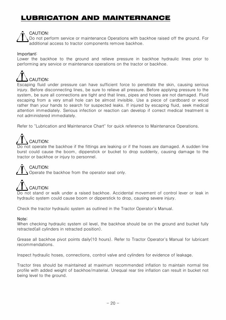
Refer to "Lubrication and Maintenance Chart" for quick reference to Maintenance Operations.
CAUTION:
CAUTION:Operate the backhoe from the operator seat only.
CAUTION:
Check the tractor hydraulic system as outlined in the Tractor Operator's Manual.
Note:
Inspect hydraulic hoses, connections, control valve and cylinders for evidence of leakage.
When checking hydraulic system oil level, the backhoe should be on the ground and bucket fullyretracted(all cylinders in retracted position).
Grease all backhoe pivot points daily(10 hours). Refer to Tractor Operator's Manual for lubricantrecommendations.
Tractor tires should be maintained at maximum recommended inflation to maintain normal tireprofile with added weight of backhoe/material. Unequal rear tire inflation can result in bucket notbeing level to the ground.
Do not perform service or maintenance Operations with backhoe raised off the ground. Foradditional access to tractor components remove backhoe.
Lower the backhoe to the ground and relieve pressure in backhoe hydraulic lines prior toperforming any service or maintenance operations on the tractor or backhoe.
Escaping fluid under pressure can have sufficient force to penetrate the skin, causing seriousinjury. Before disconnecting lines, be sure to relieve all pressure. Before applying pressure to thesystem, be sure all connections are tight and that lines, pipes and hoses are not damaged. Fluidescaping from a very small hole can be almost invisible. Use a piece of cardboard or woodrather than your hands to search for suspected leaks. If injured by escaping fluid, seek medicalattention immediately. Serious infection or reaction can develop if correct medical treatment isnot administered immediately.
Do not operate the backhoe if the fittings are leaking or if the hoses are damaged. A sudden lineburst could cause the boom, dipperstick or bucket to drop suddenly, causing damage to thetractor or backhoe or injury to personnel.
Do not stand or walk under a raised backhoe. Accidental movement of control lever or leak inhydraulic system could cause boom or dipperstick to drop, causing severe injury.
- 20 -

TROUBLE SHOOTING
This Trouble Shooting Chart is provided for reference to possible backhoe operational problems.
PROBLEM POSSIBLE CAUSE CORRECTION
Low hydraulic fluid level. Check and replenish hydraulic fluid.
Hydraulic hosesconnected improperly.
Check and correct hydraulic hose connections.
Hydraulic hoses to/fromcontrol valve blocked
Check for damage(kinked) hoses, etc.
Backhoe control valve ortractor main relief valvestuck open.
Check system pressure. Repair or replace reliefvalve. Refer to the Tractor Operator's Manual
Check system pressure.
Repair or replace pump.
Control valve linkagebroken.
Inspect. Repair as required.
Check coupler connections.
Replace coupler(s) if necessary.
Hydraulic hose ortubeline blockage.
Check for evidence of damage to hoses ortubelines that would block flow of oil betweencylinders and control valve.
Cylinder piston assemblydefective(not sealing)
Check cylinders for internal leakage as describedin service section under cylinder leakage tests.
control valve blockage.Inspect for blockage. Disassemble valve ifnecessary.
Cylinders operate in wrongdirection relative to controlvalve lever position.
Hydraulic hosesconnected incorrectly.
Correct hydraulic hose connections.
Low hydraulic fluid level. Check and refill hydraulic system to proper level.
Air leaking into suctionside of hydraulic pump.
Check for loose or defective connectionsbetween reservoir and hydraulic pump.
Hydraulic fluid foamingdue to improper hydraulicoil usage.
Refer to Tractor Operator's Manual and replacehydraulic oil using recommended hydraulic oil.
Aeration of HydraulicFluid(Generally indicatedby foamy apperance offluid).
Determine the problem that best describes the operational problem being experienced andeliminate the possible causes as listed by following the correction procedures.
Swing, Boom,Dipperstick and BucketCylinders
Low system pressuresupplied from hydraulicpump.
Quick disconnectcoupler(s) are not fullyconnected or "FlowCheck"
- 21 -

TROUBLE SHOOTING
PROBLEM POSSIBLE CAUSE CORRECTION
Low hydraulic fluid level. Check and replenish hydraulic fluid.
Cold hydraulic fluid.Allow hydraulic system to warm up to operatingtemperature.
Engine R.P.M. tooslow(hydraulic pumpR.P.M. too slow).
Increase engine speed to obtain satisfactorybackhoe operation.
Excessive weight inbucket. Material weightexceeds maximumspecified backhoecapacity.
Reduce material load.(Digging load)
Control valve linkagebinding/defective.
Check control valve linkage and repair ifworn/defective.
Aeration of hydraulicfluid
Refer to "Aeration of Hydraulic Fluid".
Quick disconnect couplerrestriction or coupler"Flow checks"
Check coupler connections. Repair or replace.
Hydraulic hose ortubelinerestriction(hoses/tubline)kinked or pinched.
Check hoses and tubelines for evidence ofrestriction.
Boom, Dipperstick orBucket cylinder pistonassembly leakage.
Check cylinders for leakage. Repair as needed.
Relief valve erratic or setbelow specifications.
Check and reset relief valve. Setting as needed.
Control valve leakinginternally.(hypassing fluidwithin valve).
Replace control valve and recheck operation.
Hydraulic Oil viscositytoo heavy or Incorrect oil
Check oil number and viscosity, Refill correcthydraulic oil.
Engine R.P.M. too slow. Increase engine R.P.M.
Excessive load - materialweight exceeds specifiedloader capacity.
Reduce Load.
Relief valve setting belowspecifications.
Check and reset relief valve setting as needed.
Bucket, Boom andDipperstick cylinderpiston assembly leakage.
Check cylinders for leakge. Repair as needed.
Control valve leakinginternally
Replace control valve and recheck operation.
Hydraulic pumpdefective.
Refer to "Hydraulic Pump Capacity Inadequate".
Inadequate lifting capacity
Slow or erratic move ofCylinders (Noisy operationof cylinders)
- 22 -

TROUBLE SHOOTING
PROBLEM POSSIBLE CAUSE CORRECTION
Hydraulic Oil viscositytoo heavy or Incorrect oil
Check oil number and viscosity, Refill correcthydraulic oil.
Excessive load in bucket.Weight exceeds specifiedbackhoe capacity.
Reduce load.
Relief valve setting belowspecifications.
Check and reset valve setting as needed.
Hydraulic hose, tubelineor quick disconnectcoupler restriction.
Check for evidence of restriction in hydraulic oilflow. Repair or replace defective components.
Backhoe drops with controlvalve spool in "centered"position (no external oilleakage evident.)
Cylinder piston assemblyleakage.
Check cylinders for leakage.
Note: A gradual drop overan extended period of timeis a normal condition.
Control valve internalleakage.
Replace control valve and recheck.
Control lever linkagebinding.
Determine origin of binding and repair.
Control valve spoolcentering is broken.
Replace centering spring.
Control valve spoolbinding in valve bodyspool bore.
Disassemble valve for inspection and repair.
Loose hydraulicconnection.
Tighten loose connections.
Defective hydraulic hose,tubeline, adapter fittingor adapter fitting o-ring.
Check for origin of oil leak and replace defectivepart.
Control valve o-ringsdefective.
Replace defective o-rings.
Control valve spool orbody damaged or worn.
Replace control valve.
Cylinder rod packing setleakage.
Check cylinders for leakage. Repair as needed.
System relief valvesqueals.
Control valve spool(s) willnot return to centeredposition.
External hydraulic fluidleakage.
- 23 -

TROUBLE SHOOTING
PROBLEM POSSIBLE CAUSE CORRECTION
Cold hydraulic fluid.Allow hydraulic fluid to warm up to operatingtemperature.
Engine R.P.M. too slow. Increase engine R.P.M.
Low hydraulic fluidsupply.
Refer to Tractor Operator's Manual for servicerecommendations.
Hydraulic hoserestriction.
Check for evidence of restriction in hydraulichoses.
Hydraulic pumpdefective.
Refer to Tractor Operator's Manual forrecommended service procedures. Replacehydraulic pump if determined to be defective.
cylinder rod bend when liftcylinders extended.
Excessive shock load onlift cylinders duringtransport.
Replace defective parts. Review and observeproper and safe operational practices.
Hydraulic pump capacityinadequate.
- 24 -

HYDRAULIC SYSTEM SCHEMATIC
Boom
Cyl
inder
Sw
ing
Cyl
inders
Left
Sta
bili
zer
Cyl
inder
Dip
pers
tick
Cyl
inder
Bucke
tC
ylin
der
Rig
ht
Sta
bili
zer
Cyl
inder
Tra
cto
r or
Pum
p K
it
- 25 -
TORQUE TIGHTENING CHART
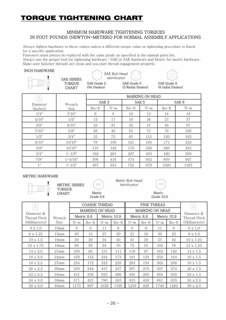
INCH HARDWARE
SAE SERIESTORQUECHART
lbs-ft N-m lbs-ft N-m lbs-ft N-m
1/4" 7/16" 6 8 10 13 14 18
5/16" 1/2" 12 17 19 26 27 37
3/8" 9/16" 23 31 35 47 49 67
7/16" 5/8" 36 48 55 75 78 106
1/2" 3/4" 55 75 85 115 120 163
9/16" 13/16" 78 106 121 164 171 232
5/8" 15/16" 110 149 170 230 240 325
3/4" 1-1/8" 192 261 297 403 420 569
7/8" 1-5/16" 306 416 474 642 669 907
1" 1-1/2" 467 634 722 979 1020 1383
METRIC SERIESTORQUECHART Metric
Grade 8.8
MARKING ON HEAD
SAE 2 SAE 5 SAE 8Diameter(Inches)
Metric Grade 10.9
SAE Grade 2(No Dashes)
SAE Grade 5(3 Radial Dashes)
SAE Grade 8(6 radial Dashes)
Always tighten hardware to these values unless a different torque value or tightening procedure is listedfor a specific application.Fasteners must always be replaced with the same grade as specified in the manual parts list.Always use the proper tool for tightening hardware : SAE or SAE hardware and Metric for metric hardware.Make sure fastener threads are clean and you start thread engagement properly.
MINIMUM HARDWARE TIGHTENING TORQUESIN FOOT POUNDS (NEWTON-METERS) FOR NORMAL ASSEMBLY APPLICATIONS
METRIC HARDWARE
WrenchSize
SAE Bolt HeadIdentification
Metric Bolt HeadIdentification
N-m lbs-ft N-m lbs-ft N-m lbs-ft N-m lbs-ft
6 x 1.0 10mm 8 6 11 8 8 6 11 8 6 x 1.0
8 x 1.25 13mm 20 15 27 20 21 16 29 22 8 x 1.0
10 x 1.5 16mm 39 29 54 40 41 30 57 42 10 x 1.25
12 x 1.75 18mm 68 50 94 70 75 55 103 76 12 x 1.25
14 x 2.0 21mm 109 80 151 111 116 87 163 120 14 x 1.5
16 x 2.0 24mm 169 125 234 173 181 133 250 184 16 x 1.5
18 x 2.5 27mm 234 172 323 239 263 194 363 268 18 x 1.5
20 x 2.5 30mm 330 244 457 337 367 270 507 374 20 x 1.5
22 x 2.5 34mm 451 332 623 460 495 365 684 505 22 x 1.5
24 x 3.0 36mm 571 421 790 583 623 459 861 635 24 x 2.0
30 x 3.0 46mm 1175 867 1626 1199 1258 928 1740 1283 30 x 2.0
Metric 8.8
FINE THREAD
MARKING ON HEAD MARKING ON HEADDiameter &
Thread Pitch(Millimeters)
WrenchSize
COARSE THREAD
Diameter &Thread Pitch(Millimeters)
Metric 10.9 Metric 8.8 Metric 10.9
- 26 -

PART ILLUSTRATIONS
GENERAL INFORMATION
Illustrations
Directional Reference
Parts Order
Instructions1. GROUP NAME : Detail classiflcation name for parts.2. SECTION NAME :Classiflcation name for parts.3. COMPONENTS : The components of an assembly are identifled by a bracket.4. NO. : Reference numbers are assiqned to parts in the figure.
INTERCHANGEABILITY : Indicates the interchangeabillty of parts due to design change
The individual parts in their normal relationship to each other. Reference numbers are usedin the illustrations. These numbers correspond to those in the "Number" column and arefollowed by the quantity required and description.
"Right hand" and "left hand" sides are determined by standing at the rear of the unit andfacing in the direction of forward travel.
Orders must give the complete description, correct part number, the total amount required,the product model, all the necessary serial numbers, the method of shipment and theshipping address.
Indicates that a new part can be used instead of an old partwhen you order this part, plese order new part.
indicates that either parts can be used.
indicates that either parts can not be used.
~4265-99999 5265-00001~
indicates that a part has a serial number break.When you order this part, please order a part according to theserial number of the Loader.
★ Due to our policy of continuously improving products, The information contained herein is subject to change withour notice.
Note : The Hydraulic Control valve installed in this Backhoe is stipulated on the Name Plate.
H : HANIL AV 80/6
- 27 -

HOSE KIT-G3033/G3033H, G3038/G3038H
REF.NO
LS PART NO PART NO DESCRIPTION QTY I.C REMARK
1 40230959 802L2-T46F9-4S NIPPLE, PT3/8×3/4-16NUF, SWIVEL 90° 1
2 40228721 80420-T3360 QUICK COUPLER, PT3/8" FEMALE 2
3 40230676 8043W-03300 DUST-CAPS, 3/8" WHITE MALE 2
4 40228729 8044W-03300 DUST-CAP, 3/8" WHITE FEMALE 2
5 40228720 80410-T3360 QUICK COUPLER, PT3/8" MALE 2
6 40230961 802N0-T46P6-32 NIPPLE, PF1/2, O-RING×PT3/8 1 wrong spec.
40228718 802N2-P63F9-42 NIPPLE, PF1/2, O-RING×3/4-16UNF, HOSE 1
7 40228757 81301-BP018 O-RING, 1BP18 1
8 40230975 80620-02012 BACKHOE HOSE ASS'Y, 4(3/4-16UNF)-1(PT1/2) 1700L(3/8) 2
9 40230968 80420-T1130 QUICK COUPLER, PT1/2 FEMALE 2
10 40230970 8043W-01100 DUST-PLUG, 1/2" WHITE MALE 1
11 40228715 802L2-T46F9-40 NIPPLE, PT3/8×3/4-16UNF, HOSE 90˚ 3
12 40230969 8043K-01100 DUST-PLUG, 1/2" BLACK MALE 1
13 40228698 50120-M540K CABLE TIE, 540mm BLACK 5
40228758 99400-00001 TEFRON TAPE 1
BLOCK
T
P2R
- 28 -
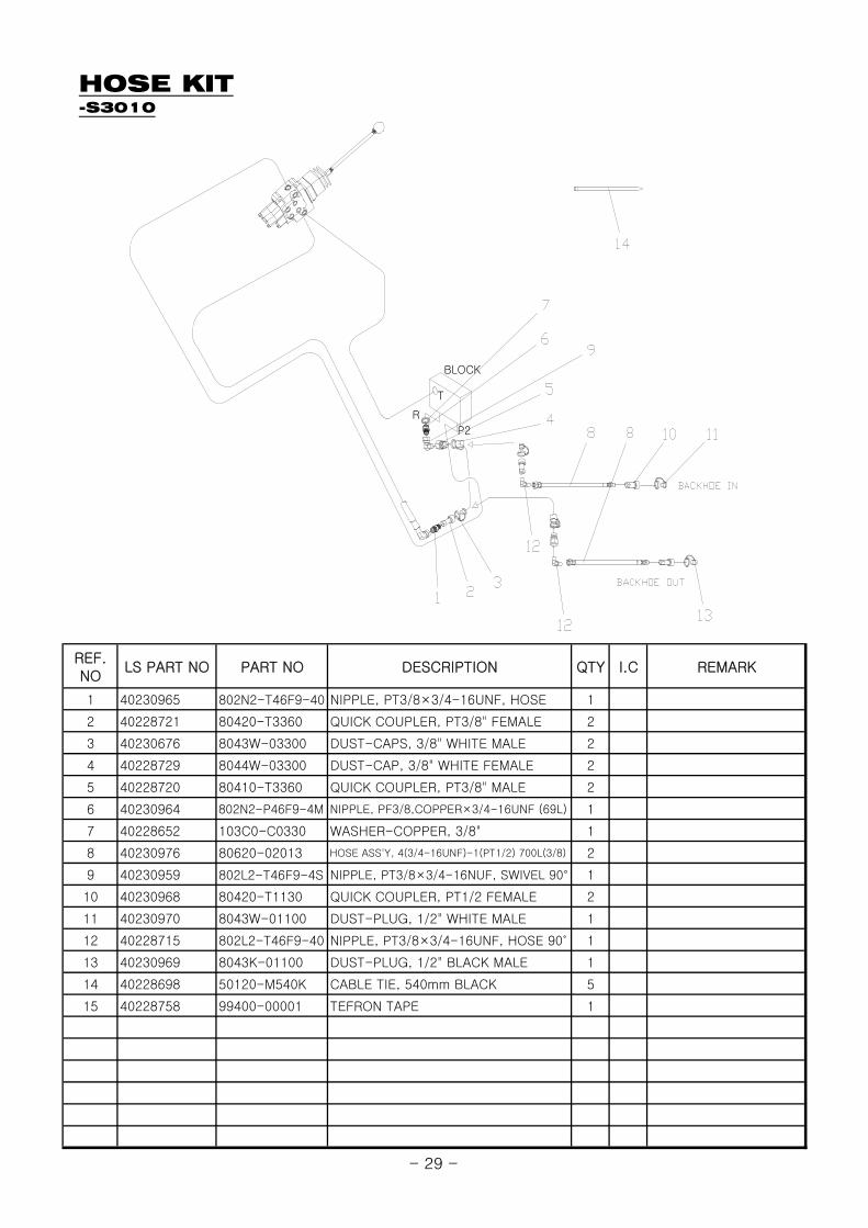
HOSE KIT-S3010
REF.NO
LS PART NO PART NO DESCRIPTION QTY I.C REMARK
1 40230965 802N2-T46F9-40 NIPPLE, PT3/8×3/4-16UNF, HOSE 1
2 40228721 80420-T3360 QUICK COUPLER, PT3/8" FEMALE 2
3 40230676 8043W-03300 DUST-CAPS, 3/8" WHITE MALE 2
4 40228729 8044W-03300 DUST-CAP, 3/8" WHITE FEMALE 2
5 40228720 80410-T3360 QUICK COUPLER, PT3/8" MALE 2
6 40230964 802N2-P46F9-4M NIPPLE, PF3/8,COPPER×3/4-16UNF (69L) 1
7 40228652 103C0-C0330 WASHER-COPPER, 3/8" 1
8 40230976 80620-02013 HOSE ASS'Y, 4(3/4-16UNF)-1(PT1/2) 700L(3/8) 2
9 40230959 802L2-T46F9-4S NIPPLE, PT3/8×3/4-16NUF, SWIVEL 90° 1
10 40230968 80420-T1130 QUICK COUPLER, PT1/2 FEMALE 2
11 40230970 8043W-01100 DUST-PLUG, 1/2" WHITE MALE 1
12 40228715 802L2-T46F9-40 NIPPLE, PT3/8×3/4-16UNF, HOSE 90˚ 1
13 40230969 8043K-01100 DUST-PLUG, 1/2" BLACK MALE 1
14 40228698 50120-M540K CABLE TIE, 540mm BLACK 5
15 40228758 99400-00001 TEFRON TAPE 1
BLOCK
R
T
P2
- 29 -
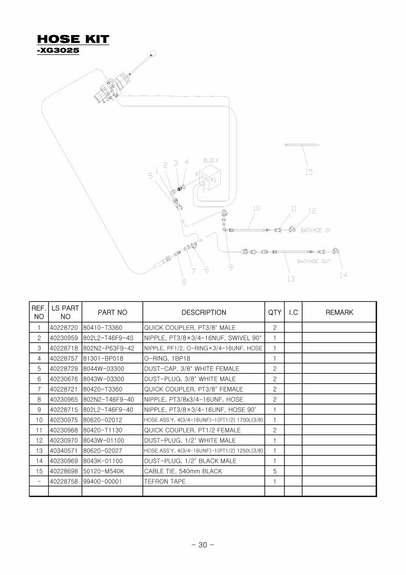
HOSE KIT-XG3025
REF.NO
LS PARTNO
PART NO DESCRIPTION QTY I.C REMARK
1 40228720 80410-T3360 QUICK COUPLER, PT3/8" MALE 2
2 40230959 802L2-T46F9-4S NIPPLE, PT3/8×3/4-16NUF, SWIVEL 90° 1
3 40228718 802N2-P63F9-42 NIPPLE, PF1/2, O-RING×3/4-16UNF, HOSE 1
4 40228757 81301-BP018 O-RING, 1BP18 1
5 40228729 8044W-03300 DUST-CAP, 3/8" WHITE FEMALE 2
6 40230676 8043W-03300 DUST-PLUG, 3/8" WHITE MALE 2
7 40228721 80420-T3360 QUICK COUPLER, PT3/8" FEMALE 2
8 40230965 802N2-T46F9-40 NIPPLE, PT3/8x3/4-16UNF, HOSE 2
9 40228715 802L2-T46F9-40 NIPPLE, PT3/8×3/4-16UNF, HOSE 90˚ 1
10 40230975 80620-02012 HOSE ASS'Y, 4(3/4-16UNF)-1(PT1/2) 1700L(3/8) 1
11 40230968 80420-T1130 QUICK COUPLER, PT1/2 FEMALE 2
12 40230970 8043W-01100 DUST-PLUG, 1/2" WHITE MALE 1
13 40340571 80620-02027 HOSE ASS'Y, 4(3/4-16UNF)-1(PT1/2) 1250L(3/8) 1
14 40230969 8043K-01100 DUST-PLUG, 1/2" BLACK MALE 1
15 40228698 50120-M540K CABLE TIE, 540mm BLACK 5
- 40228758 99400-00001 TEFRON TAPE 1
- 30 -
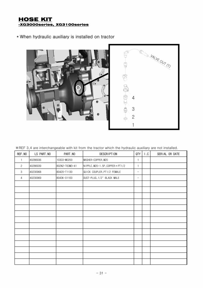
HOSE KIT-XG3000series, XG3100series
REF.NO LS PART.NO PART.NO DESCRIPTION QTY I.C SERIAL OR DATE
1 40286936 103C0-M0200 WASHER-COPPER,M20 1
2 40286939 802N2-T63M3-41 NIPPLE,M20-1.5P,COPPER×PT1/2 1
3 40230968 80420-T1130 QUICK COUPLER,PT1/2 FEMALE -
4 40230969 8043K-01100 DUST-PLUG,1/2" BLACK MALE -
*When hydraulic auxiliary is installed on tractor
※REF 3,4 are interchangeable with kit from the tractor which the hydraulic auxiliary are not installed.
1
2
3
4
VALVE OUT (T)
- 31 -
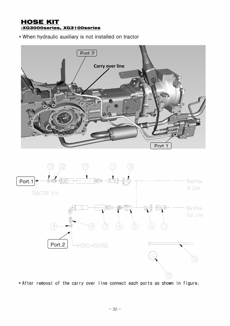
HOSE KIT-XG3000series, XG3100series
*After removal of the carry over line connect each ports as shown in figure.
*When hydraulic auxiliary is not installed on tractor
Carry over line
Port.2
Port.1
Port.1
Port.2
- 32 -

HOSE KIT-XG3000series, XG3100series
REF.NO LS PART.NO PART.NO DESCRIPTION QTY I.C SERIAL OR DATE
1 40230968 80420-T1130 QUICK COUPLER, PT1/2" FEMALE 2
4 40230969 8043K-01100 DUST PLUG,1/2 BLACK MALE 1
5 40230971 8044K-01100 DUST CAP, 1/2 BLACK FEMALE 1
6 40230967 80410-T1130 QUICK COUPLER, PT1/2" MALE 1
7 40326738 80620-07018HOSE ASS'Y, 904(3/4-16UNF)x1(PT1/2)800L (3/8)
1
8 40228716 802N2-P46F9-41NIPPLE, 3/4-16UNF HOSE xPF3/8 COPPER
1
9 40228654 103E1-C0380 SEAL BOND, 3/8" 1
10 40230970 8043W-01100 DUSE PLUG, 1/2 WHITE MALE 1
11 40326739 80620-02021HOSE ASS'Y, 4(3/4-16UNF)x1(PT1/2)1600L (3/8)
1
12 40326740 802N2-F94P6-31NIPPLE, 3/4-16UNF HOSE xPF1/2 COPPER
1
13 40228653 103E1-C0110 SEAL BOND 1/2" 1
14 40228698 50120-M540K CABLE TIE, 540mm BLACK 4
15 40228758 99400-00001 TEFLON TAPE 1
- 33 -
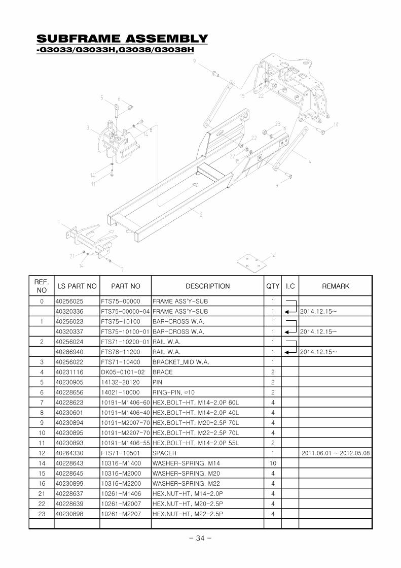
SUBFRAME ASSEMBLY-G3033/G3033H,G3038/G3038H
REF.NO
LS PART NO PART NO DESCRIPTION QTY I.C REMARK
0 40256025 FTS75-00000 FRAME ASS'Y-SUB 1
40320336 FTS75-00000-04 FRAME ASS'Y-SUB 1 2014.12.15~
1 40256023 FTS75-10100 BAR-CROSS W.A. 1
40320337 FTS75-10100-01 BAR-CROSS W.A. 1 2014.12.15~
2 40256024 FTS71-10200-01 RAIL W.A. 1
40286940 FTS78-11200 RAIL W.A. 1 2014.12.15~
3 40256022 FTS71-10400 BRACKET_MID W.A. 1
4 40231116 DK05-0101-02 BRACE 2
5 40230905 14132-20120 PIN 2
6 40228656 14021-10000 RING-PIN, ∅10 2
7 40228623 10191-M1406-60 HEX.BOLT-HT, M14-2.0P 60L 4
8 40230601 10191-M1406-40 HEX.BOLT-HT, M14-2.0P 40L 4
9 40230894 10191-M2007-70 HEX.BOLT-HT, M20-2.5P 70L 4
10 40230895 10191-M2207-70 HEX.BOLT-HT, M22-2.5P 70L 4
11 40230893 10191-M1406-55 HEX.BOLT-HT, M14-2.0P 55L 2
12 40264330 FTS71-10501 SPACER 1 2011.06.01 ~ 2012.05.08
14 40228643 10316-M1400 WASHER-SPRING, M14 10
15 40228645 10316-M2000 WASHER-SPRING, M20 4
16 40230899 10316-M2200 WASHER-SPRING, M22 4
21 40228637 10261-M1406 HEX.NUT-HT, M14-2.0P 4
22 40228639 10261-M2007 HEX.NUT-HT, M20-2.5P 4
23 40230898 10261-M2207 HEX.NUT-HT, M22-2.5P 4
- 34 -

SUBFRAME ASSEMBLY-S3010
REF.NO
LS PART NO PART NO DESCRIPTION QTY I.C REMARK
0 40231122 FTS70-00000 SUBFRAME ASS'Y 1
1 40231123 FTS70-10100 CROSS BAR W.A. 1
2 40231124 FTS70-10200 RAIL W.A. 1
3 40231125 FTS70-10300 BRACKET_MID W.A. 1
40256021 FTS70-10300-01 BRACKET_MID W.A. 1 2010.06.25~
4 40231116 DK05-0101-02 BRACE 2
5 40230905 14132-20120 PIN 2
6 40230904 14021-1000 RING PIN 2
7 40228623 10191-M1406-60 HEX.BOLT-HT, M14-2.0P 60L 4
8 40230601 10191-M1406-40 HEX.BOLT-HT, M14-2.0P 40L 6
9 40230894 10191-M2007-70 HEX.BOLT-HT, M20-2.5P 70L 4
10 40230895 10191-M2207-70 HEX.BOLT-HT, M22-2.5P 70L 4
12 40228643 10316-M1400 WASHER-SPRING, M14 10
13 40228645 10316-M2000 WASHER-SPRING, M20 4
14 40230899 10316-M2200 WASHER-SPRING, M22 4
15 40228637 10261-M1406 HEX.NUT-HT, M14-2.0P 4
16 40228639 10261-M2007 HEX.NUT-HT, M20-2.5P 4
17 40230898 10261-M2207 HEX.NUT-HT, M22-2.5P 4
1
2
9
913
16
1316
4
10
1417
65
12
8
3TRACTOR
1512
7
- 35 -
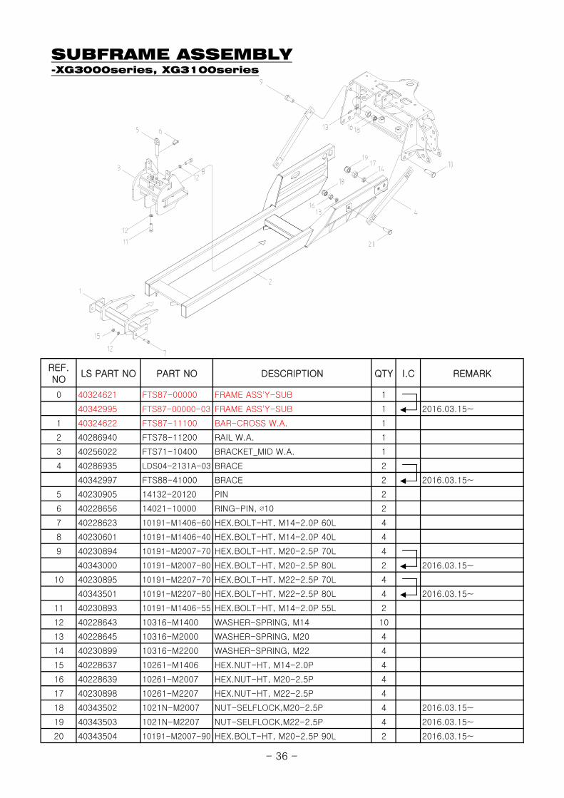
SUBFRAME ASSEMBLY-XG3000series, XG3100series
REF.NO
LS PART NO PART NO DESCRIPTION QTY I.C REMARK
0 40324621 FTS87-00000 FRAME ASS'Y-SUB 1
40342995 FTS87-00000-03 FRAME ASS'Y-SUB 1 2016.03.15~
1 40324622 FTS87-11100 BAR-CROSS W.A. 1
2 40286940 FTS78-11200 RAIL W.A. 1
3 40256022 FTS71-10400 BRACKET_MID W.A. 1
4 40286935 LDS04-2131A-03 BRACE 2
40342997 FTS88-41000 BRACE 2 2016.03.15~
5 40230905 14132-20120 PIN 2
6 40228656 14021-10000 RING-PIN, ∅10 2
7 40228623 10191-M1406-60 HEX.BOLT-HT, M14-2.0P 60L 4
8 40230601 10191-M1406-40 HEX.BOLT-HT, M14-2.0P 40L 4
9 40230894 10191-M2007-70 HEX.BOLT-HT, M20-2.5P 70L 4
40343000 10191-M2007-80 HEX.BOLT-HT, M20-2.5P 80L 2 2016.03.15~
10 40230895 10191-M2207-70 HEX.BOLT-HT, M22-2.5P 70L 4
40343501 10191-M2207-80 HEX.BOLT-HT, M22-2.5P 80L 4 2016.03.15~
11 40230893 10191-M1406-55 HEX.BOLT-HT, M14-2.0P 55L 2
12 40228643 10316-M1400 WASHER-SPRING, M14 10
13 40228645 10316-M2000 WASHER-SPRING, M20 4
14 40230899 10316-M2200 WASHER-SPRING, M22 4
15 40228637 10261-M1406 HEX.NUT-HT, M14-2.0P 4
16 40228639 10261-M2007 HEX.NUT-HT, M20-2.5P 4
17 40230898 10261-M2207 HEX.NUT-HT, M22-2.5P 4
18 40343502 1021N-M2007 NUT-SELFLOCK,M20-2.5P 4 2016.03.15~
19 40343503 1021N-M2207 NUT-SELFLOCK,M22-2.5P 4 2016.03.15~
20 40343504 10191-M2007-90 HEX.BOLT-HT, M20-2.5P 90L 2 2016.03.15~
- 36 -
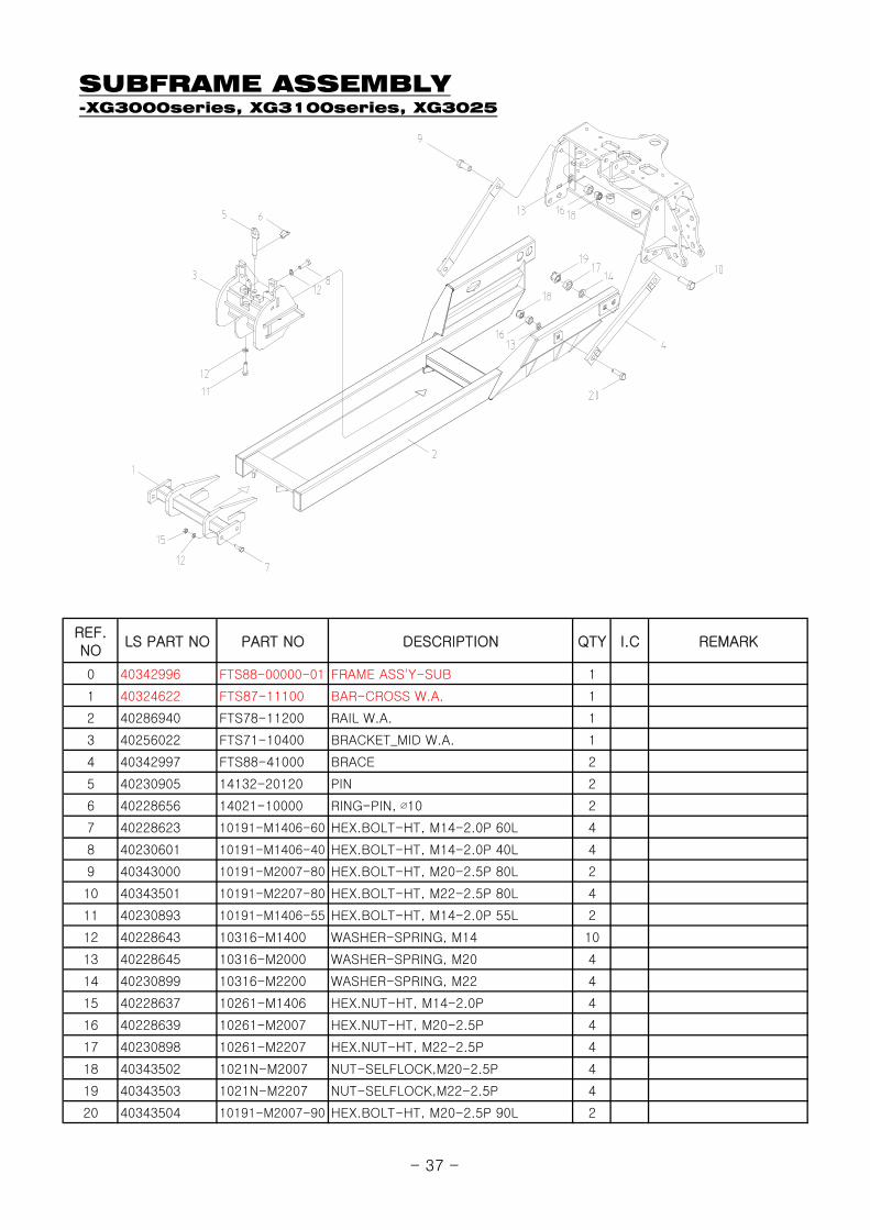
SUBFRAME ASSEMBLY-XG3000series, XG3100series, XG3025
REF.NO
LS PART NO PART NO DESCRIPTION QTY I.C REMARK
0 40342996 FTS88-00000-01 FRAME ASS'Y-SUB 1
1 40324622 FTS87-11100 BAR-CROSS W.A. 1
2 40286940 FTS78-11200 RAIL W.A. 1
3 40256022 FTS71-10400 BRACKET_MID W.A. 1
4 40342997 FTS88-41000 BRACE 2
5 40230905 14132-20120 PIN 2
6 40228656 14021-10000 RING-PIN, ∅10 2
7 40228623 10191-M1406-60 HEX.BOLT-HT, M14-2.0P 60L 4
8 40230601 10191-M1406-40 HEX.BOLT-HT, M14-2.0P 40L 4
9 40343000 10191-M2007-80 HEX.BOLT-HT, M20-2.5P 80L 2
10 40343501 10191-M2207-80 HEX.BOLT-HT, M22-2.5P 80L 4
11 40230893 10191-M1406-55 HEX.BOLT-HT, M14-2.0P 55L 2
12 40228643 10316-M1400 WASHER-SPRING, M14 10
13 40228645 10316-M2000 WASHER-SPRING, M20 4
14 40230899 10316-M2200 WASHER-SPRING, M22 4
15 40228637 10261-M1406 HEX.NUT-HT, M14-2.0P 4
16 40228639 10261-M2007 HEX.NUT-HT, M20-2.5P 4
17 40230898 10261-M2207 HEX.NUT-HT, M22-2.5P 4
18 40343502 1021N-M2007 NUT-SELFLOCK,M20-2.5P 4
19 40343503 1021N-M2207 NUT-SELFLOCK,M22-2.5P 4
20 40343504 10191-M2007-90 HEX.BOLT-HT, M20-2.5P 90L 2
- 37 -

BUCKET, DIPPERSTICK ASSEMBLY
- 38 -

BUCKET, DIPPERSTICK ASSEMBLY
REF.NO
LS PART NO PART NO DESCRIPTION QTY I.C REMARK
40231071 BT664-23100-01 BUCKET ASS'Y, 9 1
40231072 BT664-23200-01 BUCKET ASS'Y, 12 1
40231074 BT664-23400-02 BUCKET ASS'Y, 18 1
40231075 BT664-23500-02 BUCKET ASS'Y, 24 1
40231076 BT664-23600-02 BUCKET ASS'Y, 36 1
2 40231056 BT200-22100 DIPPERSTICK ASS'Y 1
3 40231079 BT664-25100 LINK ASS'Y 1
4 40231078 BT664-24200-02 LINK-RH 1
5 40231077 BT664-24100-02 LINK-LH 1
6 40231094 BT664-71600-01 PIN, ∅30-195.5L 2
8 40231092 BT664-71400-02 PIN, ∅30-154.5L 2
9 40230880 10121-M0803-60 HEX.BOLT, M8-1.25P 60L 4
10 40230896 1021N-M0803 NUT-SELFLOCK, M8-1.25P 4
11 40228707 802G0-T1900 NIPPLE,GREASE, 1/8" 4
13 40231037 BH11-0116 SOCKET BRACKET 1
14 40231036 BH11-0115 SOCKET 1
15 40228698 50120-M540K CABLE TIE, 540mm BLACK 2
16 40228607 10121-M0803-50 HEX.BOLT, M8-1.25P 50L 2
17 40228629 10211-M0803 HEX.NUT, M8-1.25P 2
18 40230979 83040-4440D BUSHING, 404440 2
19 40230978 83030-3440D BUSHING, 303440 2
20 40230907 2010-3025 BUSHING, 252830 4
21 40231097 BT664-72000 PIN, ∅25-195.5L 2
22 40230884 10121-M1004-60 HEX.BOLT, M10-1.5P 60L 2
23 40228634 1021N-M1004 NUT-SELFLOCK, M10-1.5P 2
1
- 39 -
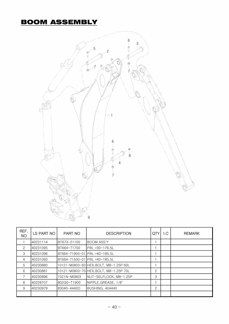
BOOM ASSEMBLY
REF.NO
LS PART NO PART NO DESCRIPTION QTY I.C REMARK
1 40231114 BT673-21100 BOOM ASS'Y 1
2 40231095 BT664-71700 PIN, ∅30-176.5L 1
3 40231096 BT664-71900-01 PIN, ∅40-185.5L 1
4 40231093 BT664-71500-01 PIN, ∅40-185.5L 1
5 40230880 10121-M0803-60 HEX.BOLT, M8-1.25P 60L 1
6 40230881 10121-M0803-70 HEX.BOLT, M8-1.25P 70L 2
7 40230896 1021N-M0803 NUT-SELFLOCK, M8-1.25P 3
8 40228707 802G0-T1900 NIPPLE,GREASE, 1/8" 1
9 40230979 83040-4440D BUSHING, 404440 2
9
2
7
6
1
5
7
7
4
8
6
3
- 40 -

SWING FRAME ASSEMBLY
REF.NO
LS PART NO PART NO DESCRIPTION QTY I.C REMARK
1 40231080 BT664-31000-03 SWING FRAME ASS'Y 1
2 40231106 BT664-74100 SWING CYL.PIN, ∅25×118L 2
3 40231098 BT664-72100-03 PIN, ∅40-117L 2
4 40231099 BT664-72200-02 LOCK 1
40343506 BTS08-20100 LOCK 1 2016.03.15~
5 40231101 BT664-72400 PIN, ∅22-190L 1
6 40231100 BT664-72300 HANDLE SET 1
40343507 BTS08-30100 HANDLE SET 1 2016.03.15~
7 40231031 BC04-5100 PLASTIC BALL 1
8 40231102 BT664-72500 LOCK 1
9 40230946 6002-0122 SNAP RING, C22 2
10 40231055 BN06-0108 SPRING 1
11 40231092 BT664-71400-02 PIN, ∅30-154.5L 1
12 40228634 1021N-M1004 NUT-SELFLOCK, M10-1.5P 1
13 40230896 1021N-M0803 NUT-SELFLOCK, M8-1.25P 6
14 40230880 10121-M0803-60 HEX.BOLT, M8-1.25P 60L 3
15 40228607 10121-M0803-50 HEX.BOLT, M8-1.25P 50L 2
16 40230878 10121-M0803-25 HEX.BOLT, M8-1.25P 25L 1
17 40230879 10121-M0803-35 HEX.BOLT, M8-1.25P 35L 1
18 40229894 10121-M1004-35 HEX.BOLT, M10-1.5P 35L 1
19 40228630 10211-M1004 HEX.NUT, M10-1.5P 1
- 41 -
MAINFRAME ASSEMBLY
- 42 -

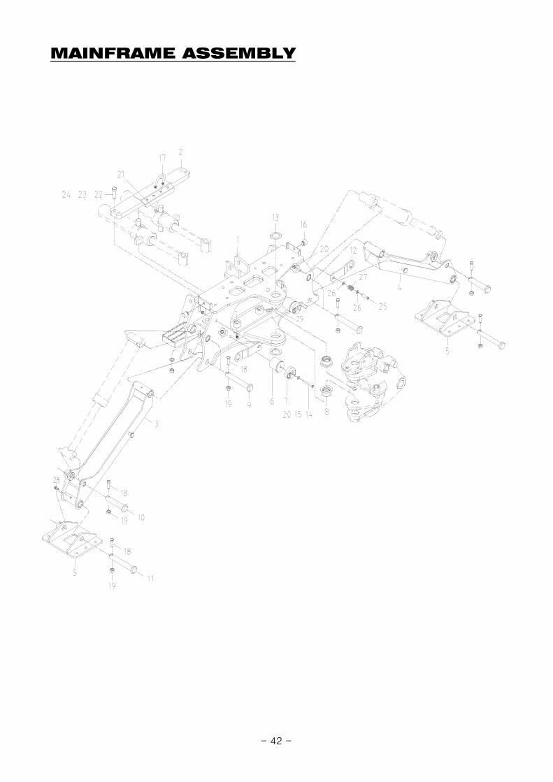
MAINFRAME ASSEMBLY
REF.NO
LS PART NO PART NO DESCRIPTION QTY I.C REMARK
1 40231069 BT664-11000-05 MAIN FRAME ASS'Y 1
2 40231065 BT651-52100-01 CROSS BAR 1
3 40231088 BT664-62100-02 STABILIZER ASS'Y-RH 1
4 40231086 BT664-61100-02 STABILIZER ASS'Y-LH 1
5 40231087 BT664-61200 FOOT PLATE 2
6 40231064 BT651-31600 BRACKET-CUSHION 2
7 40230876 1002-B004 CUSHION 2
8 40231066 BT651-75110-03 BUSHING, 405030 2
9 40231089 BT664-71100 PIN, ∅25-171L 4
10 40231090 BT664-71200 PIN, ∅25-139L 2
11 40231091 BT664-71300 PIN, ∅25-175L 2
12 40231104 BT664-72800-02 STABILIZER LOCK 2
13 40231105 BT664-73120 WASHER 2
14 40230885 10121-M1004-90 HEX.BOLT, M10-1.5P 90L 2
15 40228641 10316-M1000 WASHER-SPRING, M10 2
16 40230877 1002-B005 RUBBER STOP 2
17 40231035 BH09-0117 U-BOLT, ∅40,5/16-18 1
18 40228607 10121-M0803-50 HEX.BOLT, M8-1.25P 50L 8
19 40230896 1021N-M0803 NUT-SELFLOCK, M8-1.25P 8
20 40228634 1021N-M1004 NUT-SELFLOCK, M10-1.5P 4
21 40230901 1202-0361 HEX.NUT, 5/16 4
22 40230888 10121-M1606-60 HEX.BOLT, M16-2.0P 60L 4
23 40228644 10316-M1600 WASHER-SPRING, M16 4
24 40228636 1021N-M1606 NUT-SELFLOCK, M16-2.0P 4
25 40230883 10121-M1004-50 HEX.BOLT, M10-1.5P 50L 2
26 40228647 10321-M1000 WASHER-PLAIN, M10 4
27 40231034 BH07-0113 SPRING 2
28 40230956 802G0-11900 NIIPPLE GREASE, PT1/8 8
29 40230957 802G1-11900 NIIPPLE GREASE, PT1/8 45˚ 9
- 43 -

SEAT, CONTROL ASSEMBLY(HANIL)
27
2425
2218
2019
27
8
6
426
151615
23
30
21
16
1114
1310
2
3
5
27
26
23 26
28
23
24
7
9
25
24
1
29
17
12
31
- 44 -
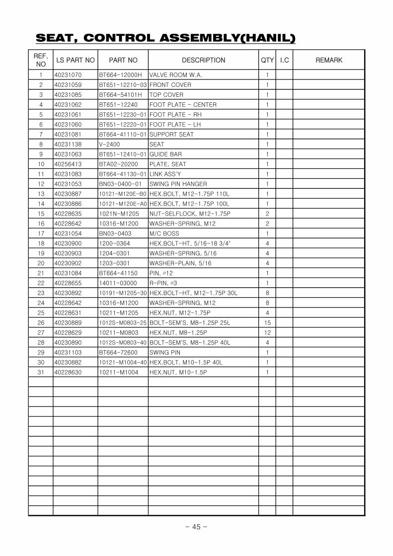
SEAT, CONTROL ASSEMBLY(HANIL)
REF.NO
LS PART NO PART NO DESCRIPTION QTY I.C REMARK
1 40231070 BT664-12000H VALVE ROOM W.A. 1
2 40231059 BT651-12210-03 FRONT COVER 1
3 40231085 BT664-54101H TOP COVER 1
4 40231062 BT651-12240 FOOT PLATE - CENTER 1
5 40231061 BT651-12230-01 FOOT PLATE - RH 1
6 40231060 BT651-12220-01 FOOT PLATE - LH 1
7 40231081 BT664-41110-01 SUPPORT SEAT 1
8 40231138 V-2400 SEAT 1
9 40231063 BT651-12410-01 GUIDE BAR 1
10 40256413 BTA02-20200 PLATE, SEAT 1
11 40231083 BT664-41130-01 LINK ASS'Y 1
12 40231053 BN03-0400-01 SWING PIN HANGER 1
13 40230887 10121-M120E-B0 HEX.BOLT, M12-1.75P 110L 1
14 40230886 10121-M120E-A0 HEX.BOLT, M12-1.75P 100L 1
15 40228635 1021N-M1205 NUT-SELFLOCK, M12-1.75P 2
16 40228642 10316-M1200 WASHER-SPRING, M12 2
17 40231054 BN03-0403 M/C BOSS 1
18 40230900 1200-0364 HEX.BOLT-HT, 5/16-18 3/4" 4
19 40230903 1204-0301 WASHER-SPRING, 5/16 4
20 40230902 1203-0301 WASHER-PLAIN, 5/16 4
21 40231084 BT664-41150 PIN, ∅12 1
22 40228655 14011-03000 R-PIN, ∅3 1
23 40230892 10191-M1205-30 HEX.BOLT-HT, M12-1.75P 30L 8
24 40228642 10316-M1200 WASHER-SPRING, M12 8
25 40228631 10211-M1205 HEX.NUT, M12-1.75P 4
26 40230889 1012S-M0803-25 BOLT-SEM'S, M8-1.25P 25L 15
27 40228629 10211-M0803 HEX.NUT, M8-1.25P 12
28 40230890 1012S-M0803-40 BOLT-SEM'S, M8-1.25P 40L 4
29 40231103 BT664-72600 SWING PIN 1
30 40230882 10121-M1004-40 HEX.BOLT, M10-1.5P 40L 1
31 40228630 10211-M1004 HEX.NUT, M10-1.5P 1
- 45 -
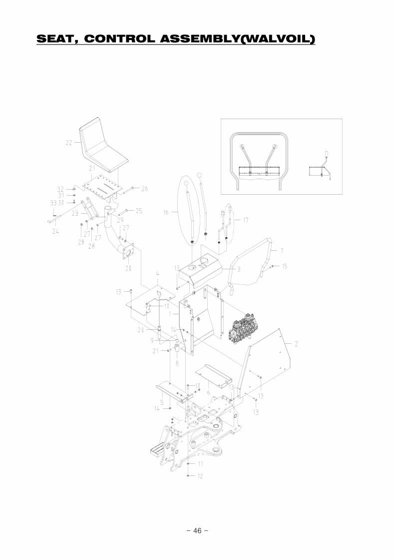
SEAT, CONTROL ASSEMBLY(WALVOIL)
- 46 -

SEAT, CONTROL ASSEMBLY(WALVOIL)
REF.NO
LS PART NO PART NO DESCRIPTION QTY I.C REMARK
1 40294001 BTV02-20200 VALVE ROOM W.A. 1
40343508 BTV08-20200 VALVE ROOM W.A. 1 2016.03.15~
2 40294002 BTV02-20301 COVER, FRONT 1
3 40294003 BTV02-40102-01 TOP COVER 1
4 40231062 BT651-12240 FOOT PLATE - CENTER 1
5 40231061 BT651-12230-01 FOOT PLATE - RH 1
6 40231060 BT651-12220-01 FOOT PLATE - LH 1
7 40294004 BTV02-70001P GUIDE BAR 1
8 40231053 BN03-0400-01 SWING PIN HANGER 1
9 40231054 BN03-0403 M/C BOSS 1
10 40230892 10191-M1205-30 HEX.BOLT-HT, M12-1.75P 30L 6
11 40228642 10316-M1200 WASHER-SPRING, M12 6
12 40228631 10211-M1205 HEX.NUT, M12-1.75P 6
13 40230889 1012S-M0803-25 BOLT-SEM'S, M8-1.25P 25L 15
14 40228629 10211-M0803 HEX.NUT, M8-1.25P 12
15 40230890 1012S-M0803-40 BOLT-SEM'S, M8-1.25P 40L 4
16 40294005 BTV02-31000 BOOT LEVER ASS'Y 2
40343509 BTV08-31000 BOOT LEVER ASS'Y 2 2016.03.15~
17 40294006 BTV02-32000 HAND LEVER 2
40343510 BTV08-32000 HAND LEVER 2 2016.03.15~
18 40231103 BT664-72600 SWING PIN 1
19 40230882 10121-M1004-40 HEX.BOLT, M10-1.5P 40L 1
20 40231081 BT664-41110-01 SUPPORT SEAT 1
21 40256413 BTA02-20200 PLATE, SEAT 1
22 40231138 V-2400 SEAT 1
23 40231083 BT664-41130-01 LINK ASS'Y 1
24 40231084 BT664-41150 PIN, ∅12 1
25 40255401 10121-M1205-A0 HEX.BOLT, M12-1.75P 100L 1
26 40230887 10121-M120E-B0 HEX.BOLT, M12-1.75P 110L 1
27 40228642 10316-M1200 WASHER-SPRING, M12 6
28 40228635 1021N-M1205 NUT-SELFLOCK, M12-1.75P 2
29 40228615 10191-M1205-35 HEX.BOLT-HT, M12-1.75P 35L 4
30 40230900 1200-0364 HEX.BOLT-HT, 5/16-18 3/4" 4
31 40228640 10316-M0800 WASHER-SPRING, M8 4
32 40228646 10321-M0800 WASHER-PLAIN, M8 4
33 40228655 14011-03000 R-PIN, ∅3 1
- 47 -

HOSE FITTING ASSEMBLY(HANIL)
3334
F
f
F' f'
f'-f' , F'-F'30
29 e-e , E-E
LH
RH
25
22
17
2419
16
3
21
16
CONTROL VALVE
19
17
1315
14
18
19
19
19
36
37
38
20
35
16
16
19
16
a-a , A-A
f-f , F-Fc-c , d-db-b , B-B
31
28
27
26
2
6
5
5
7
F'
f'
d
c
b
B
32
32
812
f
F
e
E
d
c
c
b
B
a
A
23
A
24
4
a
19
d
d
c
20
VALVE
VALVE IN (P)
OUT (T)
1
1916
25
11
10
98
18
E19
16
e
- 48 -
HOSE FITTING ASSEMBLY(HANIL)
REF.NO
LS PART NO PART NO DESCRIPTION QTY I.C REMARK
1 40230891 1012S-M0803-50 BOLT-SEM'S, M8-1.25P 50L 4
2 40230928 226702 BUCKET CYLINDER ASSEMBLY 1
3 40230925 226701 DIPPERSTICK CYLINDER ASSEMBLY 1
4 40230931 226703 BOOM CYLINDER ASSEMBLY 1
5 40230918 225806 SWING CYLINDER ASSEMBLY 2
6 40230910 224304 STABILIZER CYLINDER ASSEMBLY-LH 1
7 40230913 224305 STABILIZER CYLINDER ASSEMBLY-RH 1
8 40230948 6003-0204 ADAPTER LONG, 1/2-20UNF×3/4-16UNF, O-RING 4
9 40230949 6003-0205 ORIFICE LONG, 1/2-20UNF×3/4-16UNF, O-RING 2
10 40230947 6003-0203 ADAPTER SHORT, 1/2-20UNF×3/4-16UNF, O-RING 4
11 40230950 6003-0206 ORIFICE SHORT, 1/2-20UNF×3/4-16UNF, O-RING 2
12 40230951 6003-0302 ADAPTER ELBOW, 3/4-16UNF×7/8-14UNF, O-RING 90˚ 2
13 40230952 6003-0408 NIPPLE, PT1/2×3/4-16UNF 2
14 40230971 8044K-01100 DUST-CAP, 1/2" BLACK FEMALE 2
15 40230967 80410-T1130 QUICK COUPLER, PT1/2 MALE 2
16 40230953 6004-0205 NIPPLE, PF1/4, O-RING×1/2-20UNF 16
17 40230962 802N1-F67F7-50 NIPPLE, 9/16-18UNF×1/2-20UNF 2
18 40230943 5004-0034 O-RING, AS568 #908, AS568 #908 12
19 40230700 81300-0P011 O-RING, P11 16
20 40230944 5004-0078 O-RING, AS568 #910, AS568 #910 2
21 40231109 BT664-83100 NIPPLE KIT, 1/2-20UNF×1/2-20UNF, NUT 2
22 40294007 BT500-01000 PIPE ASS'Y 1
23 40294008 BT500-02000 PIPE ASS'Y 1
24 40230963 802N1-P26F7-52 ADAPTER, PF1/4×9/16-18UNF 2
25 40231038 BH30-0100 HOSE ASS'Y, 1/4×4×4×550L 2
26 40231039 BH30-0200 HOSE ASS'Y, 1/4×904×4×950L 2
27 40231040 BH30-0300 HOSE ASS'Y, 1/4×904×4×1300L 4
28 40231110 BT664-83120 HOSE ASS'Y, 1/4×904×4×2500L 2
29 40231111 BT664-83130 HOSE ASS'Y, 1/4×904×4×2530L 2
30 40231112 BT664-83140 HOSE ASS'Y, 1/4×4×4G/W×900L 2
31 40231113 BT664-83150 HOSE ASS'Y, 1/4×904×4×1850L 2
32 40230977 80630-01010 HOSE ASS'Y, 4(7/8-14UNF)-4(7/8-14UNF) 2100L(1/2) 2
33 40228698 50120-M540K CABLE TIE, 540mm BLACK 3
34 40231115 COM02-11101 FIX, PIPE 2
35 40230896 1021N-M0803 NUT-SELFLOCK, M8-1.25P 4
36 40230958 802L0-T63FA-32 NIPPLE, PT1/2×7/8-14UNF, O-RING 90˚ 1
37 40230955 801K1-13000 CHECK VALVE, PT1/2-0.5K 1
38 40230966 802N3-T63FA-30 NIPPLE, PT1/2×7/8-14UNF, HOSE 1
- 49 -
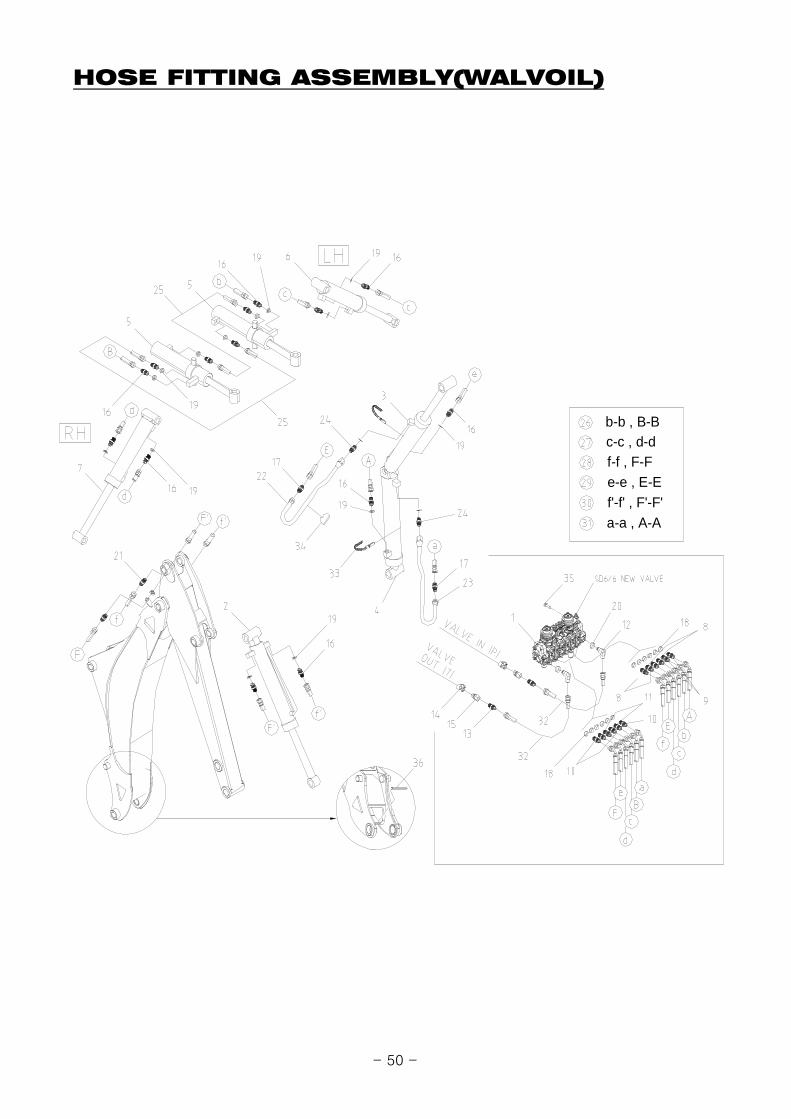
HOSE FITTING ASSEMBLY(WALVOIL)
f'-f' , F'-F'e-e , E-E
a-a , A-A
f-f , F-Fc-c , d-db-b , B-B
- 50 -
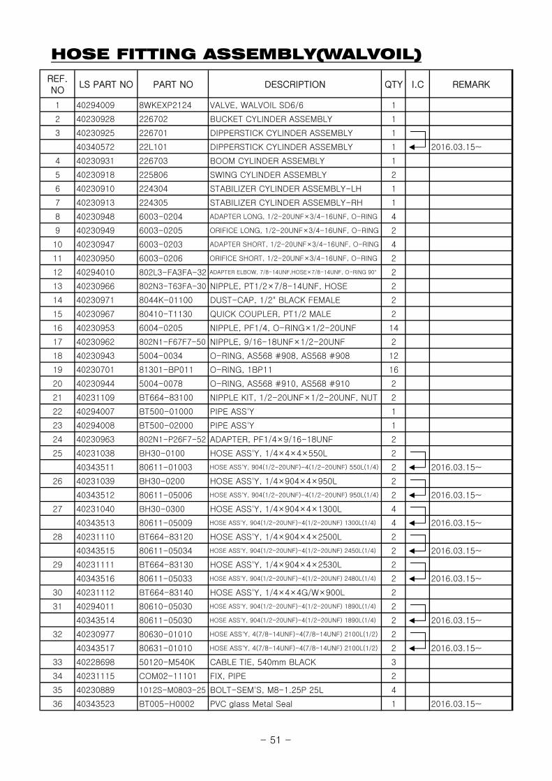
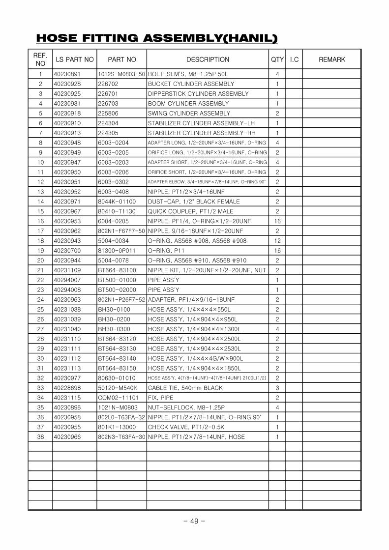
HOSE FITTING ASSEMBLY(WALVOIL)
REF.NO
LS PART NO PART NO DESCRIPTION QTY I.C REMARK
1 40294009 8WKEXP2124 VALVE, WALVOIL SD6/6 1
2 40230928 226702 BUCKET CYLINDER ASSEMBLY 1
3 40230925 226701 DIPPERSTICK CYLINDER ASSEMBLY 1
40340572 22L101 DIPPERSTICK CYLINDER ASSEMBLY 1 2016.03.15~
4 40230931 226703 BOOM CYLINDER ASSEMBLY 1
5 40230918 225806 SWING CYLINDER ASSEMBLY 2
6 40230910 224304 STABILIZER CYLINDER ASSEMBLY-LH 1
7 40230913 224305 STABILIZER CYLINDER ASSEMBLY-RH 1
8 40230948 6003-0204 ADAPTER LONG, 1/2-20UNF×3/4-16UNF, O-RING 4
9 40230949 6003-0205 ORIFICE LONG, 1/2-20UNF×3/4-16UNF, O-RING 2
10 40230947 6003-0203 ADAPTER SHORT, 1/2-20UNF×3/4-16UNF, O-RING 4
11 40230950 6003-0206 ORIFICE SHORT, 1/2-20UNF×3/4-16UNF, O-RING 2
12 40294010 802L3-FA3FA-32 ADAPTER ELBOW, 7/8-14UNF,HOSE×7/8-14UNF, O-RING 90° 2
13 40230966 802N3-T63FA-30 NIPPLE, PT1/2×7/8-14UNF, HOSE 2
14 40230971 8044K-01100 DUST-CAP, 1/2" BLACK FEMALE 2
15 40230967 80410-T1130 QUICK COUPLER, PT1/2 MALE 2
16 40230953 6004-0205 NIPPLE, PF1/4, O-RING×1/2-20UNF 14
17 40230962 802N1-F67F7-50 NIPPLE, 9/16-18UNF×1/2-20UNF 2
18 40230943 5004-0034 O-RING, AS568 #908, AS568 #908 12
19 40230701 81301-BP011 O-RING, 1BP11 16
20 40230944 5004-0078 O-RING, AS568 #910, AS568 #910 2
21 40231109 BT664-83100 NIPPLE KIT, 1/2-20UNF×1/2-20UNF, NUT 2
22 40294007 BT500-01000 PIPE ASS'Y 1
23 40294008 BT500-02000 PIPE ASS'Y 1
24 40230963 802N1-P26F7-52 ADAPTER, PF1/4×9/16-18UNF 2
25 40231038 BH30-0100 HOSE ASS'Y, 1/4×4×4×550L 2
40343511 80611-01003 HOSE ASS'Y, 904(1/2-20UNF)-4(1/2-20UNF) 550L(1/4) 2 2016.03.15~
26 40231039 BH30-0200 HOSE ASS'Y, 1/4×904×4×950L 2
40343512 80611-05006 HOSE ASS'Y, 904(1/2-20UNF)-4(1/2-20UNF) 950L(1/4) 2 2016.03.15~
27 40231040 BH30-0300 HOSE ASS'Y, 1/4×904×4×1300L 4
40343513 80611-05009 HOSE ASS'Y, 904(1/2-20UNF)-4(1/2-20UNF) 1300L(1/4) 4 2016.03.15~
28 40231110 BT664-83120 HOSE ASS'Y, 1/4×904×4×2500L 2
40343515 80611-05034 HOSE ASS'Y, 904(1/2-20UNF)-4(1/2-20UNF) 2450L(1/4) 2 2016.03.15~
29 40231111 BT664-83130 HOSE ASS'Y, 1/4×904×4×2530L 2
40343516 80611-05033 HOSE ASS'Y, 904(1/2-20UNF)-4(1/2-20UNF) 2480L(1/4) 2 2016.03.15~
30 40231112 BT664-83140 HOSE ASS'Y, 1/4×4×4G/W×900L 2
31 40294011 80610-05030 HOSE ASS'Y, 904(1/2-20UNF)-4(1/2-20UNF) 1890L(1/4) 2
40343514 80611-05030 HOSE ASS'Y, 904(1/2-20UNF)-4(1/2-20UNF) 1890L(1/4) 2 2016.03.15~
32 40230977 80630-01010 HOSE ASS'Y, 4(7/8-14UNF)-4(7/8-14UNF) 2100L(1/2) 2
40343517 80631-01010 HOSE ASS'Y, 4(7/8-14UNF)-4(7/8-14UNF) 2100L(1/2) 2 2016.03.15~
33 40228698 50120-M540K CABLE TIE, 540mm BLACK 3
34 40231115 COM02-11101 FIX, PIPE 2
35 40230889 1012S-M0803-25 BOLT-SEM'S, M8-1.25P 25L 4
36 40343523 BT005-H0002 PVC glass Metal Seal 1 2016.03.15~
- 51 -

BUCKET CYLINDER ASSEMBLY
REF.NO
LS PART NO PART NO DESCRIPTION QTY I.C REMARK
1 40230928 226702 BUCKET CYLINDER ASSEMBLY 1
2 40230929 226702-R ROD ASS'Y 1
3 40228867 OC60-7037 CAP OUTER, ∅60-70-37L 1
4 40228827 IC60-3555 COVER INNER, ∅60×35×55L 1
5 40228766 DSSD-R035 DUST,SDR, 35×43×5/6.5 1
6 40228884 UPSK-Y035 PACKING U, SKY, SKY 35-45-6 1
7 40228880 UPIS-I035 PACKING U, ISI, 35-45-6 1
8 40228872 OR1B-G055 O-RING, 1BG55 2
9 40228768 DU03-5020 BUSHING DU, 35×39×20 1
10 40228876 PI60-2746 PISTON, ∅60-27-46L 1
11 40228870 OR1B-G027 O-RING, 1BG27 2
12 40228882 UPOS-I060 PACKING U, OSI, 60-50-6 2
13 40228878 TRBR-0060 RING-BACKUP, 60-50-3 2
14 40228886 WEWR-0060 WEARING, WR, 60-55-15 1
15 40228864 NTP0-U100-C NUT, 1-14UN 1
16 40230930 226702-T TUBE ASS'Y 1
17 40231134 GNIT-018I NIPPLE,GREASE, 1/8" 2
18 40228823 IA60-3555 SEAL KIT HEAD, NO.3~8 1
19 40228874 PA60-2746 PISTON ASS'Y, NO.9~13 1
18
19
17
~
21
2
17
3
16
15
12
13
10
14
13
12
1111
56
7
4
8
89
17
- 52 -
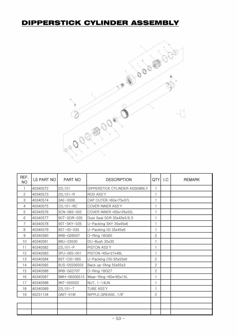
DIPPERSTICK CYLINDER ASSEMBLY
REF.NO
LS PART NO PART NO DESCRIPTION QTY I.C REMARK
1 40340572 22L101 DIPPERSTICK CYLINDER ASSEMBLY 1
2 40340573 22L101-R ROD ASS'Y 1
3 40340574 3AE-0006 CAP OUTER ∅60x∅75x37L 1
4 40340575 22L101-RC COVER INNER ASS'Y 1
5 40340576 3CN-065-002 COVER INNER ∅65x∅35x55L 1
6 40340577 9DT-SDR-035 Dust Seal SDR 35x43x5/6.5 1
7 40340578 9ST-SKY-035 U-Packing SKY 35x45x6 1
8 40340579 9ST-ISI-035 U-Packing ISI 35x45x6 1
9 40340580 9RB-G0600T O-Ring 1BG60 2
10 40340581 9BU-03530 DU-Bush 35x30 1
11 40340582 22L101-P PISTON ASS'Y 1
12 40340583 3PU-065-001 PISTON ∅65x∅27x46L 1
13 40340584 9ST-OSI-065 U-Packing OSI 65x55x6 2
14 40340585 9US-05506503 Back up-Ring 55x65x3 2
15 40340586 9RB-G0270T O-Ring 1BG27 2
16 40340587 9WH-06006515 Wear-Ring ∅60x∅65x15L 1
17 40340588 9NT-000002 NUT, 1-14UN 1
18 40340589 22L101-T TUBE ASS'Y 1
19 40231134 GNIT-018I NIPPLE,GREASE, 1/8" 2
- 53 -
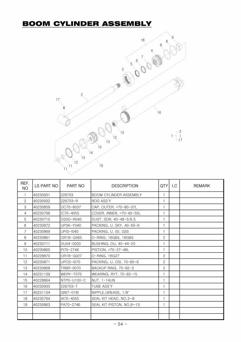
BOOM CYLINDER ASSEMBLY
REF.NO
LS PART NO PART NO DESCRIPTION QTY I.C REMARK
1 40230931 226703 BOOM CYLINDER ASSEMBLY 1
2 40230932 226703-R ROD ASS'Y 1
3 40230859 OC70-8037 CAP, OUTER, ∅70-80-37L 1
4 40230766 IC70-4055 COVER, INNER, ∅70-40-55L 1
5 40230710 DSSD-R040 DUST, SDR, 40-48-5/6.5 1
6 40230872 UPSK-Y040 PACKING, U, SKY, 40-50-6 1
7 40230869 UPIS-I040 PACKING, U, ISI, G55 1
8 40230861 OR1B-G065 O-RING, 1BG65, 1BG65 2
9 40230711 DU04-0020 BUSHING, DU, 40-44-20 1
10 40230865 PI70-2746 PISTION, ∅70-27-46L 1
11 40228870 OR1B-G027 O-RING, 1BG27 2
12 40230871 UPOS-I070 PACKING, U, OSI, 70-60-6 2
13 40230868 TRBR-0070 BACKUP RING, 70-60-3 2
14 40231139 WERY-T070 WEARING, RYT, 70-65-15 1
15 40228864 NTP0-U100-C NUT, 1-14UN 1
16 40230933 226703-T TUBE ASS'Y 1
17 40231134 GNIT-018I NIPPLE,GREASE, 1/8" 1
18 40230764 IA70-4055 SEAL KIT HEAD, NO.3~8 1
19 40230863 PA70-2746 SEAL KIT PISTON, NO.9~13 1
16
1211
11
14
13
13
10
15
12
4
98
8
3
76
5
2
17
18
19
12
~
17
- 54 -
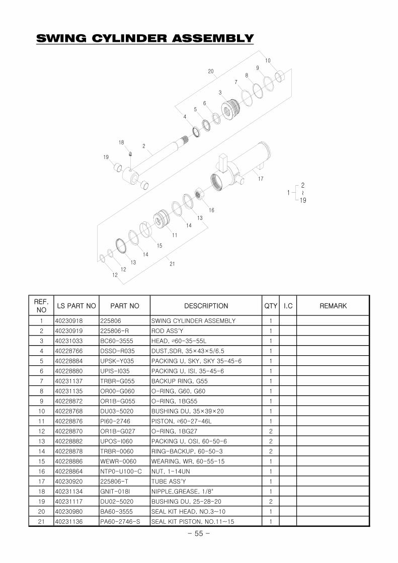
SWING CYLINDER ASSEMBLY
REF.NO
LS PART NO PART NO DESCRIPTION QTY I.C REMARK
1 40230918 225806 SWING CYLINDER ASSEMBLY 1
2 40230919 225806-R ROD ASS'Y 1
3 40231033 BC60-3555 HEAD, ∅60-35-55L 1
4 40228766 DSSD-R035 DUST,SDR, 35×43×5/6.5 1
5 40228884 UPSK-Y035 PACKING U, SKY, SKY 35-45-6 1
6 40228880 UPIS-I035 PACKING U, ISI, 35-45-6 1
7 40231137 TRBR-G055 BACKUP RING, G55 1
8 40231135 OR00-G060 O-RING, G60, G60 1
9 40228872 OR1B-G055 O-RING, 1BG55 1
10 40228768 DU03-5020 BUSHING DU, 35×39×20 1
11 40228876 PI60-2746 PISTON, ∅60-27-46L 1
12 40228870 OR1B-G027 O-RING, 1BG27 2
13 40228882 UPOS-I060 PACKING U, OSI, 60-50-6 2
14 40228878 TRBR-0060 RING-BACKUP, 60-50-3 2
15 40228886 WEWR-0060 WEARING, WR, 60-55-15 1
16 40228864 NTP0-U100-C NUT, 1-14UN 1
17 40230920 225806-T TUBE ASS'Y 1
18 40231134 GNIT-018I NIPPLE,GREASE, 1/8" 1
19 40231117 DU02-5020 BUSHING DU, 25-28-20 2
20 40230980 BA60-3555 SEAL KIT HEAD, NO.3~10 1
21 40231136 PA60-2746-S SEAL KIT PISTON, NO.11~15 1
20
21
12
~
19
218
5
4
6
3
78
9
10
1212
13
14
15
11
14
16
13
17
19
- 55 -
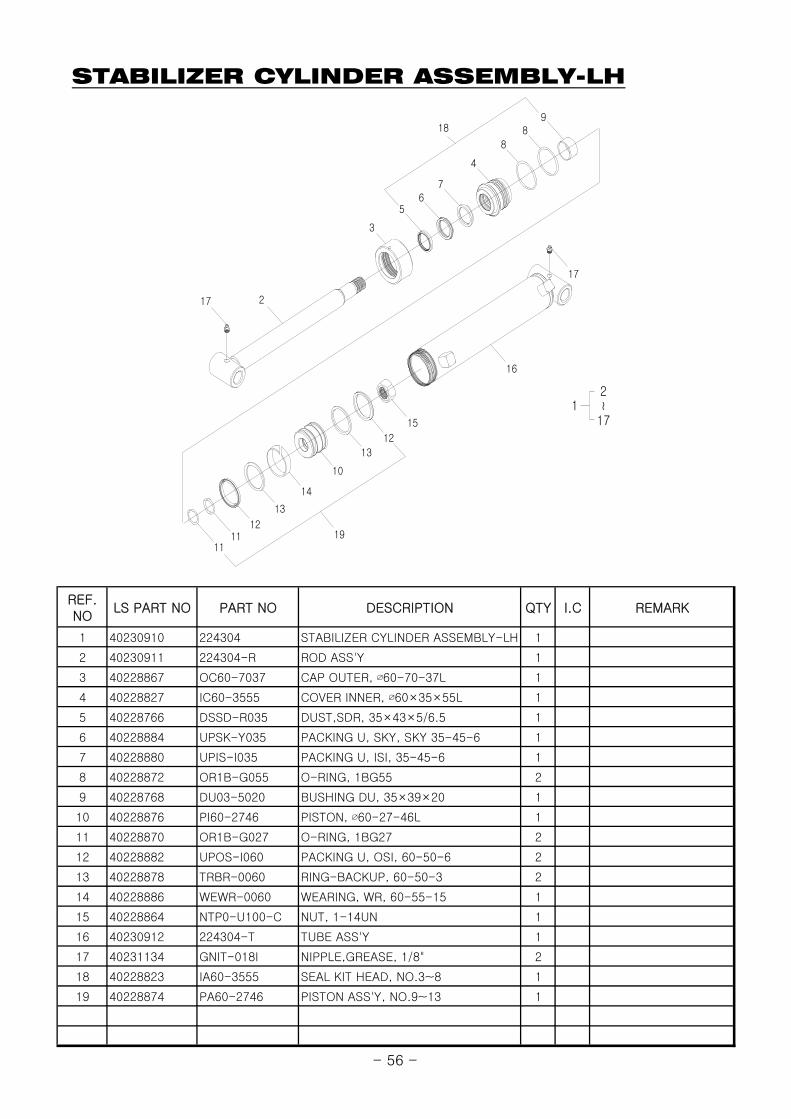
STABILIZER CYLINDER ASSEMBLY-LH
REF.NO
LS PART NO PART NO DESCRIPTION QTY I.C REMARK
1 40230910 224304 STABILIZER CYLINDER ASSEMBLY-LH 1
2 40230911 224304-R ROD ASS'Y 1
3 40228867 OC60-7037 CAP OUTER, ∅60-70-37L 1
4 40228827 IC60-3555 COVER INNER, ∅60×35×55L 1
5 40228766 DSSD-R035 DUST,SDR, 35×43×5/6.5 1
6 40228884 UPSK-Y035 PACKING U, SKY, SKY 35-45-6 1
7 40228880 UPIS-I035 PACKING U, ISI, 35-45-6 1
8 40228872 OR1B-G055 O-RING, 1BG55 2
9 40228768 DU03-5020 BUSHING DU, 35×39×20 1
10 40228876 PI60-2746 PISTON, ∅60-27-46L 1
11 40228870 OR1B-G027 O-RING, 1BG27 2
12 40228882 UPOS-I060 PACKING U, OSI, 60-50-6 2
13 40228878 TRBR-0060 RING-BACKUP, 60-50-3 2
14 40228886 WEWR-0060 WEARING, WR, 60-55-15 1
15 40228864 NTP0-U100-C NUT, 1-14UN 1
16 40230912 224304-T TUBE ASS'Y 1
17 40231134 GNIT-018I NIPPLE,GREASE, 1/8" 2
18 40228823 IA60-3555 SEAL KIT HEAD, NO.3~8 1
19 40228874 PA60-2746 PISTON ASS'Y, NO.9~13 1
18
19
12
~
17
16
17 2
3
76
5
98
8
4
1211
11
14
13
13
10
12
15
17
- 56 -

STABILIZER CYLINDER ASSEMBLY-RH
REF.NO
LS PART NO PART NO DESCRIPTION QTY I.C REMARK
1 40230913 224305 STABILIZER CYLINDER ASSEMBLY-RH 1
2 40230914 224305-R ROD ASS'Y 1
3 40228867 OC60-7037 CAP OUTER, ∅60-70-37L 1
4 40228827 IC60-3555 COVER INNER, ∅60×35×55L 1
5 40228766 DSSD-R035 DUST,SDR, 35×43×5/6.5 1
6 40228884 UPSK-Y035 PACKING U, SKY, SKY 35-45-6 1
7 40228880 UPIS-I035 PACKING U, ISI, 35-45-6 1
8 40228872 OR1B-G055 O-RING, 1BG55 2
9 40228768 DU03-5020 BUSHING DU, 35×39×20 1
10 40228876 PI60-2746 PISTON, ∅60-27-46L 1
11 40228870 OR1B-G027 O-RING, 1BG27 2
12 40228882 UPOS-I060 PACKING U, OSI, 60-50-6 2
13 40228878 TRBR-0060 RING-BACKUP, 60-50-3 2
14 40228886 WEWR-0060 WEARING, WR, 60-55-15 1
15 40228864 NTP0-U100-C NUT, 1-14UN 1
16 40230915 224305-T TUBE ASS'Y 1
17 40231134 GNIT-018I NIPPLE,GREASE, 1/8" 2
18 40228823 IA60-3555 SEAL KIT HEAD, NO.3~8 1
19 40228874 PA60-2746 PISTON ASS'Y, NO.9~13 1
15
17 2
3
76
5
98
8
4
1211
11
14
13
13
10
12
18
19
12
~
17
16
17
- 57 -

CONTROL VALVE ASSEMBLY-HANIL AV 80/6
10
18
17
18
15
8
27
46
102
0
3
6
912
28
37
29 38
44
45
35
6
23 28
89
36
34
10
2
14
6 12
41
32
26
25
31
18
35
27 47
9 8
21
13
17
11
24
17
24
186 12
42
43
33
36
4
22
19
4
15
6
47
42
18
17
18
527
29
28
8
6
8
15
9
29
27
28
10
18
18
31
32
34
36
35
49
45
18 10
3
12
52
50
51
17
18
30
27
6 13
36
41
35
40
31
39
37
30 38
40
39
31
50
17
18
10
18
16
9 8
18
17
48
16
4
9
18
33
28
- 58 -

CONTROL VALVE ASSEMBLY-HANIL AV 80/6
REF.NO
LS PART NO PART NO DESCRIPTION QTY I.C REMARK
0 40230982 BC04-0000-P CONTROL VALVE ASS'Y 1
1 40230983 BC04-0100 BLOCK-BA TYPE(INLET) 1
2 40230984 BC04-0200 BLOCK-HB TYPE(BOOM) 1
3 40230985 BC04-0300 BLOCK-HA TYPE 2
4 40230986 BC04-0400 BLOCK-EA TYPE 3
5 40230987 BC04-0500 BLOCK-GB TYPE (OUTLET) 1
6 40230988 BC04-0600 O-RING 7
7 40230989 BC04-0700 PLUG ASS'Y 1
8 40230990 BC04-0800 POPPET-CHECK 6
9 40230991 BC04-0900 SPRING-CHECK 6
10 40230992 BC04-1000 PLUG-CHECK ASS'Y 6
11 40230993 BC04-1100 M.R.V.ASS'Y 1
12 40230994 BC04-1200 O.R.V.ASS'Y 4
13 40230995 BC04-1300 A.C.V.ASS'Y 2
14 40230996 BC04-1400 SPOOL ASS'Y-FLOAT 1
15 40230997 BC04-1500 SPOOL ASS'Y-STD 3
16 40230998 BC04-1600 SPOOL ASS'Y-STABILIZER 2
17 40230999 BC04-1700 RETURN CAP 6
18 40231000 BC04-1800 WRENCH BOLT 18
19 40231001 BC04-1900 HOUSING-DETENT 1
20 40231002 BC04-2000 SOCKET-DETENT 1
21 40231003 BC04-2100 BALL-DETENT 4
22 40231004 BC04-2200 SLEEVE-DETENT 1
23 40231005 BC04-2300 SPRING-RETURN 1
24 40231006 BC04-2400 WRENCH BOLT 2
25 40231007 BC04-2500 O-RING 1
26 40231008 BC04-2600 SEAL KIT ASS'Y-FLOAT 1
27 40231009 BC04-2700 O-RING 5
28 40231010 BC04-2800 DUST WIPER 5
29 40231011 BC04-2900 SEAL PLATE 3
30 40231012 BC04-3000 BRACKET-STABILIZER 2
31 40231013 BC04-3100 WRENCH BOLT 6
32 40231014 BC04-3200 BRACKET-JOINT 2
33 40231015 BC04-3300 SUPPORT-JOINT 2
34 40231016 BC04-3400 BLOCK-JOINT 2
35 40231017 BC04-3500 SUPPORT-BALL 6
36 40231018 BC04-3600 NYLON NUT 6
37 40231019 BC04-3700 LEVER-STABILIZER 2
38 40231020 BC04-3800 PIN 4
39 40231021 BC04-3900 WASHER-PIN 4
40 40231022 BC04-4000 SNAP PIN 4
41 40231023 BC04-4100 SPRING PIN 4
42 40231024 BC04-4200 NUT 8
43 40231025 BC04-4300 TIE BOLT 4
44 40231026 BC04-4400 BOOT , CONTROL 2
45 40231027 BC04-4500 HAND LEVER 2
46 40231028 BC04-4600 BOOT , CONTROL 2
47 40231029 BC04-4700 HAND LEVER 2
48 40230981 BC01-2400 PLASTIC BALL 2
49 40231030 BC04-4900 LEVER STICK 2
50 40228630 10211-M1004 HEX.NUT, M10-1.5P 4
51 40231031 BC04-5100 PLASTIC BALL 2
52 40231032 BC04-5200 LEVER STICK 2
- 59 -
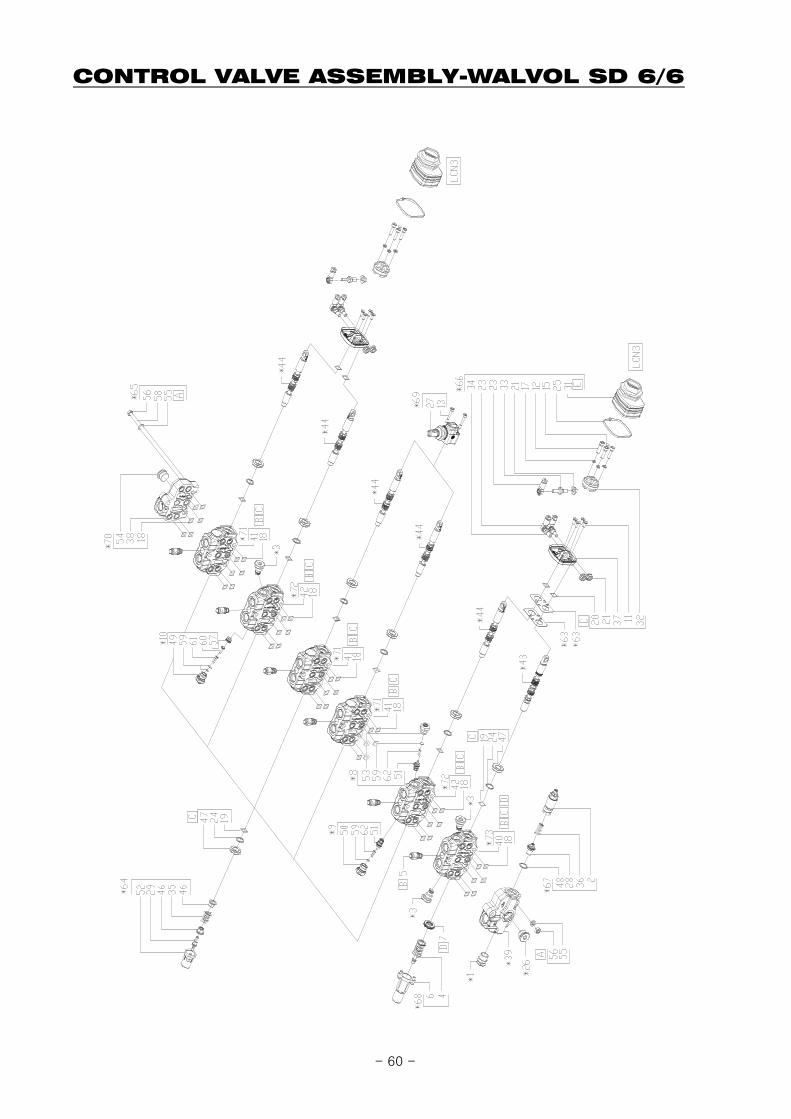
CONTROL VALVE ASSEMBLY-WALVOL SD 6/6
- 60 -

CONTROL VALVE ASSEMBLY-WALVOL SD 6/6
REF.NO LS PART.NO PART.NO DESCRIPTION QTY I.C SERIAL OR DATE
1 40308224 YTAP623282-H PLUG SV/VMP5 1 * Order code for spare parts
3 40308222 XTAP524280 PLUG P3T/SD6 3 * Order code for spare parts
8 40308217 KEXPE0000033 VALVE KIT U(G3)/SD6 1 * Order code for spare parts
9 40308213 5KIT306113-W VALVE KIT U(G3)/SD6 1 * Order code for spare parts
10 40308212 5KIT206113A-W VALVE KIT P(G3)/SD5-SD6 1 * Order code for spare parts
39 40307884 3FIA106800-H COVER-INLET FE/SD6-SAE10 1 * Order code for spare parts
43 40307880 3CU2243130 SPOOL 5BY(13QN)/SD6 1 * Order code for spare parts
44 40307879 3CU2210130 SPOOL 1/SD6 5 * Order code for spare parts
54 40307896 3XTAP826160-K PLUG TCEI SAE 10 2 * Order code for spare parts
63 40324627 3GUA167050 GASKET 2 * Order code for spare parts
64 40324628 5V08105001-H END-CAP KIT 1 * Order code for spare parts
65 40324629 5TIR108311-H TIE ROD KIT SD6/6 1 * Order code for spare parts
66 40324630 5CLO306101-W LCN KIT 2 TYPE / 3 TYPE 1 * Order code for spare parts
67 40324631 5KIT105213 MRV 1 * Order code for spare parts
68 40324632 5V13405020 CONTROL KIT 1 * Order code for spare parts
69 40324633 5LEV105000-H LEVER KIT 1 * Order code for spare parts
70 40324634 612305007 FIANCATA FS SD6/RD-SAE10 1 * Order code for spare parts
71 40324635 5EL1068010 KIT ELEMENT SD6/QH-SAE8 3 * Order code for spare parts
72 40324636 5EL1068001 KIT ELEMENTO SD6/P-SAE8 2 * Order code for spare parts
73 40324637 5EL1068205A KIT ELEMENTO SD6/P-SAE8/5BY(13QN) 1 * Order code for spare parts
- 61 -
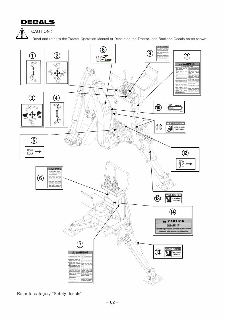
DECALSCAUTION :
Refer to category "Safety decals"
Read and refer to the Tractor Operation Manual or Decals on the Tractor. and Backhoe Decals on as shown.
⑪
⑦
⑥
⑦
⑩
⑬
⑬
②
③ ④
①
⑫
⑤
⑨
⑭
⑧
- 62 -
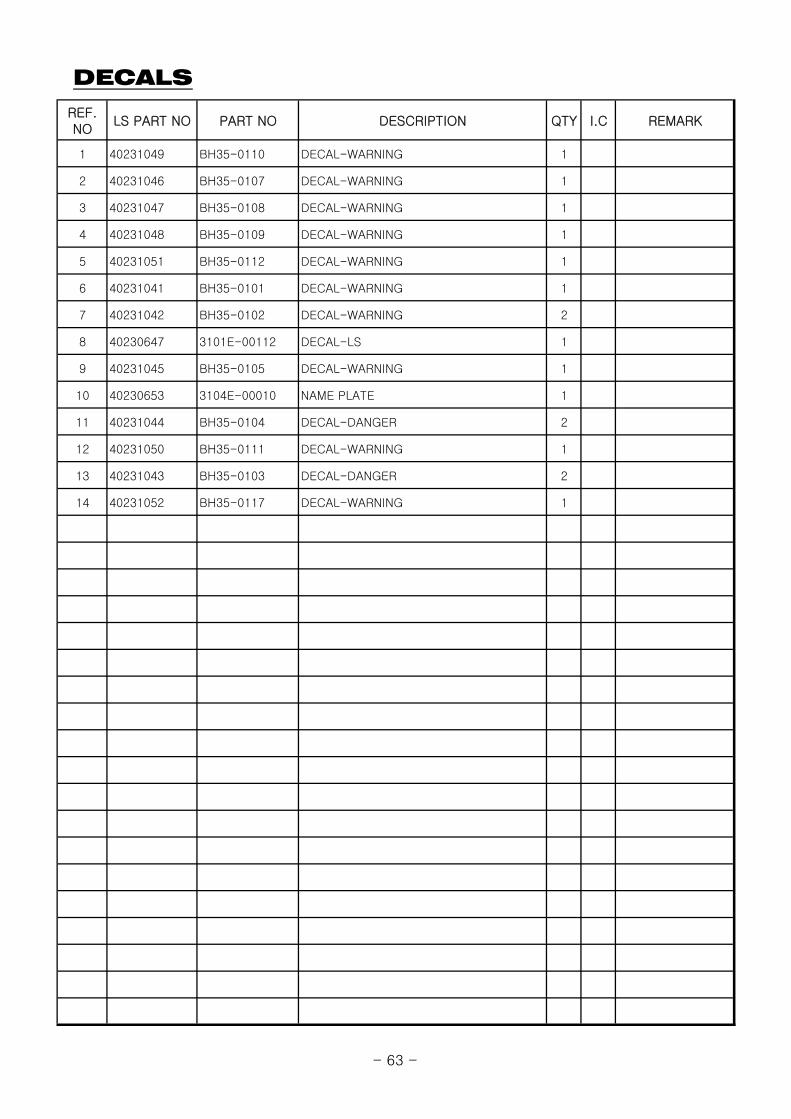
DECALS
REF.NO
LS PART NO PART NO DESCRIPTION QTY I.C REMARK
1 40231049 BH35-0110 DECAL-WARNING 1
2 40231046 BH35-0107 DECAL-WARNING 1
3 40231047 BH35-0108 DECAL-WARNING 1
4 40231048 BH35-0109 DECAL-WARNING 1
5 40231051 BH35-0112 DECAL-WARNING 1
6 40231041 BH35-0101 DECAL-WARNING 1
7 40231042 BH35-0102 DECAL-WARNING 2
8 40230647 3101E-00112 DECAL-LS 1
9 40231045 BH35-0105 DECAL-WARNING 1
10 40230653 3104E-00010 NAME PLATE 1
11 40231044 BH35-0104 DECAL-DANGER 2
12 40231050 BH35-0111 DECAL-WARNING 1
13 40231043 BH35-0103 DECAL-DANGER 2
14 40231052 BH35-0117 DECAL-WARNING 1
- 63 -