Embed Size (px)
Citation preview

LRFR Methodology
Topic Description
The application and basis of the Load and Resistance Factor Rating procedures of the new AASHTO Manual for Condition Evaluation and the Florida Structure Manual are discussed.
Speaker Biography
Professor Mertz teaches bridge engineering at the University of Delaware, and is the Director of the University’s Center for Innovative Bridge Engineering (CIBrE). Previous to his appointment to the University, he was an Associate of the bridge design firm of Modjeski & Masters, Inc.
Dennis was the Co-Principal Investigator of the NCHRP research project which wrote the original edition of the AASHTO LRFD Bridge Design Specifications. He continues to be active in its further development and implementation.
All of Professor Mertz’s engineering degrees are from Lehigh University in Bethlehem, Pennsylvania. He is also a Professional Engineer in the Commonwealth of Pennsylvania.
Dennis Mertz
Session 47
University of Delaware
1
Summer 2006 Design Conference 1
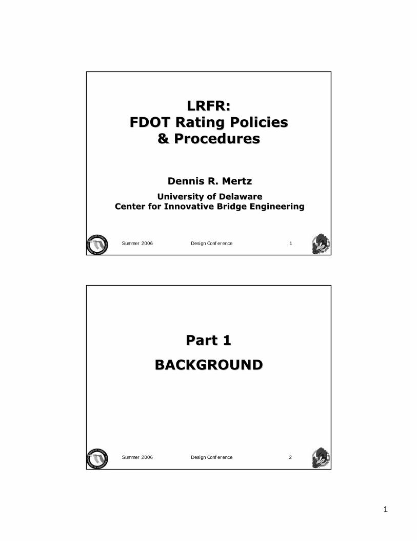
LRFR: LRFR: FDOT Rating Policies FDOT Rating Policies
& Procedures& Procedures
Dennis R. MertzDennis R. Mertz
University of Delaware University of Delaware Center for Innovative Bridge EngineeringCenter for Innovative Bridge Engineering
Summer 2006 Design Conference 2
Part 1Part 1
BACKGROUNDBACKGROUND
2
Summer 2006 Design Conference 3
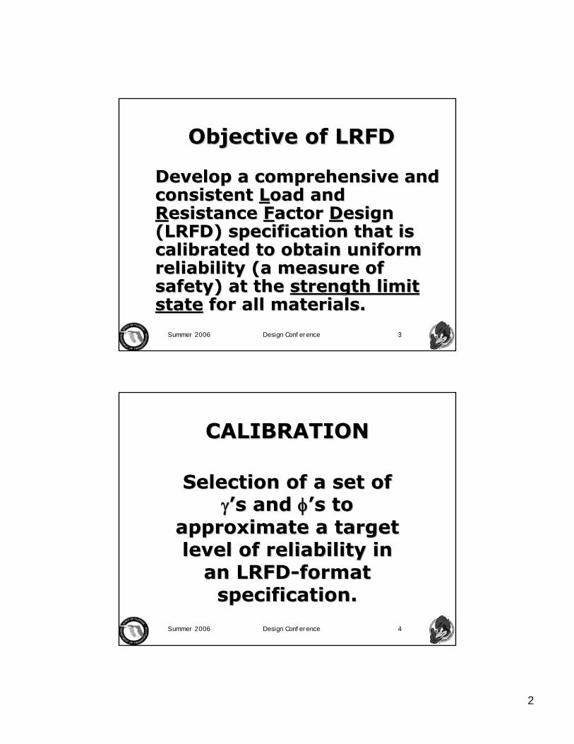
Objective of LRFDObjective of LRFD
Develop a comprehensive and Develop a comprehensive and consistent consistent LLoad and oad and RResistance esistance FFactor actor DDesign esign (LRFD) specification that is (LRFD) specification that is calibrated to obtain uniform calibrated to obtain uniform reliability (a measure of reliability (a measure of safety) at the safety) at the strength limit strength limit statestate for all materials.for all materials.
Summer 2006 Design Conference 4
CALIBRATIONCALIBRATION
Selection of a set of Selection of a set of γγ’’s and s and φφ’’s to s to
approximate a target approximate a target level of reliability in level of reliability in
an LRFDan LRFD--format format specification.specification.

3
Summer 2006 Design Conference 5
WhatWhat’’s s notnot LRFD?LRFD?•• New limit states,New limit states,•• New, more complex liveNew, more complex live--load load
distribution factors,distribution factors,•• New unifiedNew unified--concrete shear design concrete shear design
using modified compressionusing modified compression--field field theory,theory,
•• StrutStrut--andand--tie model for concrete, tie model for concrete, andand
•• Many other stateMany other state--ofof--thethe--art art additions.additions.
Summer 2006 Design Conference 6
Limit StatesLimit States
•• Service limit states,Service limit states,•• FatigueFatigue--andand--fracture limit states,fracture limit states,•• Strength limit states, andStrength limit states, and•• ExtremeExtreme--event limit states.event limit states.

4
Summer 2006 Design Conference 7
Only the strength limit states of Only the strength limit states of the the LRFD SpecificationsLRFD Specifications are are
calibrated based upon the theory calibrated based upon the theory of structural reliability, wherein of structural reliability, wherein statistical load and resistance statistical load and resistance
data are required.data are required.
The other limit states are based The other limit states are based upon the design criteria of the upon the design criteria of the
Standard SpecificationsStandard Specifications..
Summer 2006 Design Conference 8
Calibration consists of up to Calibration consists of up to three steps:three steps:
•• ReliabilityReliability--based calibration,based calibration,•• Calibration or comparison to past Calibration or comparison to past
practice, andpractice, and•• Liberal doses of engineering Liberal doses of engineering
judgment.judgment.
5
Summer 2006 Design Conference 9
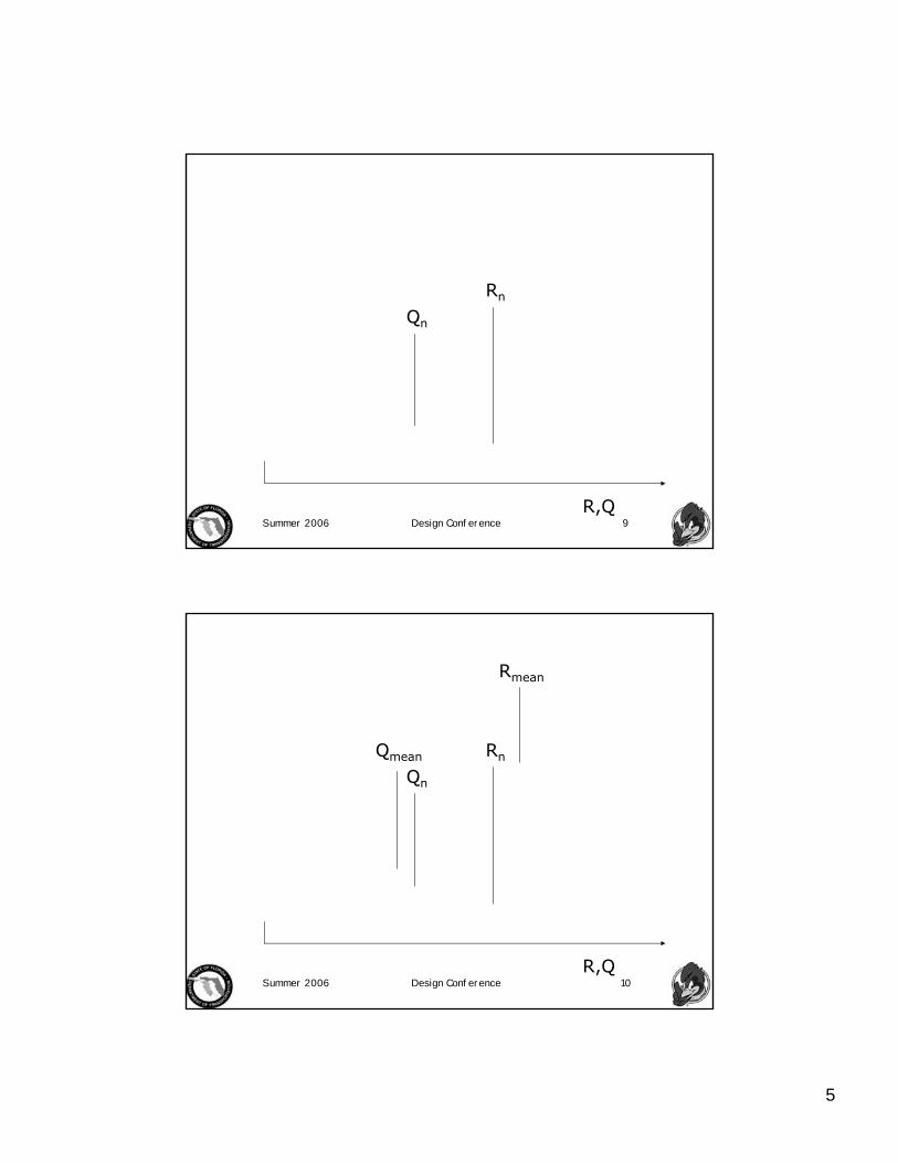
Qn
Rn
R,Q
Summer 2006 Design Conference 10
Qmean
Rmean
Qn
Rn
R,Q
6
Summer 2006 Design Conference 11
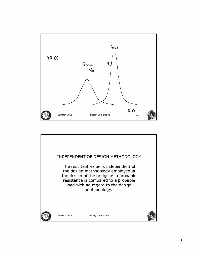
Qmean
Rmean
Qn
Rn
f(R,Q)
R,Q
Summer 2006 Design Conference 12
The resultant value is independent of The resultant value is independent of the design methodology employed in the design methodology employed in the design of the bridge as a probable the design of the bridge as a probable resistance is compared to a probable resistance is compared to a probable
load with no regard to the design load with no regard to the design methodology.methodology.
INDEPENDENT OF DESIGN METHODOLOGYINDEPENDENT OF DESIGN METHODOLOGY

7
Summer 2006 Design Conference 13R-Q
(R-Q)mean
βσ
Summer 2006 Design Conference 14
THE TARGET RELIABILITY THE TARGET RELIABILITY INDEX INDEX ββ IS A UNIQUE IS A UNIQUE
QUANTITY.QUANTITY.
Many different sets of Many different sets of γγ’’s s and and φφ’’s can be selected to s can be selected to
achieve the unique achieve the unique reliability index reliability index ββ..
8
Summer 2006 Design Conference 15
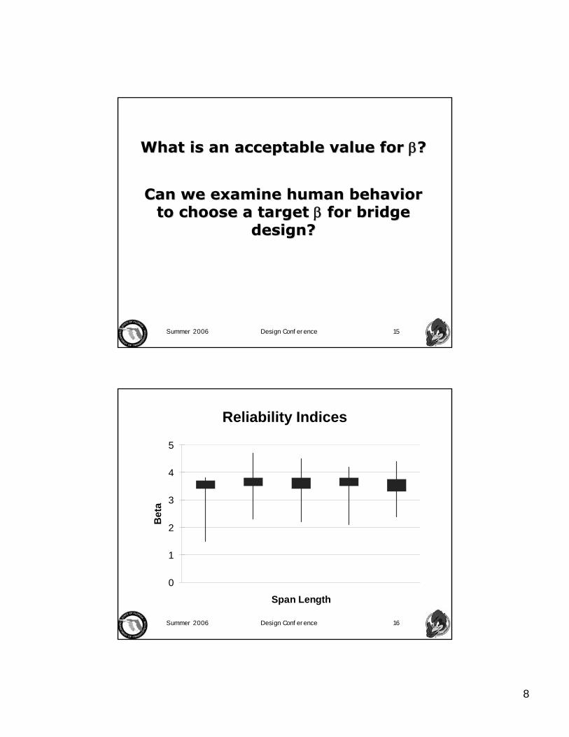
What is an acceptable value for What is an acceptable value for ββ??
Can we examine human behavior Can we examine human behavior to choose a target to choose a target ββ for bridge for bridge
design?design?
Summer 2006 Design Conference 16
Reliability Indices
0
1
2
3
4
5
Span Length
Bet
a

9
Summer 2006 Design Conference 17
If load and resistance are normal If load and resistance are normal random variables,random variables,
22)( QRQR σσσ +=−
β =Rmean − Qmean
σ R2 + σQ
2
andand
Summer 2006 Design Conference 18
LRFD requires that:LRFD requires that:
φR ≥ γ iQii∑
And the nominal And the nominal design resistance is design resistance is
defined as:defined as:
Rn =Rmean
λ

10
Summer 2006 Design Conference 19
From the definitions of From the definitions of ββ and and λλ
Rmean =Qmean +β σR2 +σQ
2 =λRn
butbut
φRn ≥ γ iQii∑
Summer 2006 Design Conference 20
Finally, solving for Finally, solving for φφyieldsyields
φ =λR γ iQi
i∑
Qmean + β σ R2 + σQ
2
With three With three ““unknowns,unknowns,”” φφ, the , the γγii’’ssand and ββ
11
Summer 2006 Design Conference 21
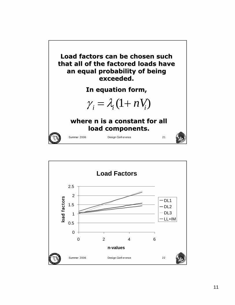
Load factors can be chosen such Load factors can be chosen such that all of the factored loads have that all of the factored loads have
an equal probability of being an equal probability of being exceeded.exceeded.
In equation form,In equation form,
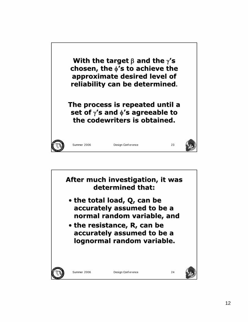
γ i = λi (1+ nVi)where n is a constant for all where n is a constant for all
load components.load components.
Summer 2006 Design Conference 22
Load Factors
0
0.5
1
1.5
2
2.5
0 2 4 6
n-values
DL1DL2DL3LL+IM
12
Summer 2006 Design Conference 23
With the target With the target ββ and the and the γγ’’s s chosen, the chosen, the φφ’’s to achieve the s to achieve the approximate desired level of approximate desired level of reliability can be determinedreliability can be determined..
The process is repeated until a The process is repeated until a set of set of γγ’’s and s and φφ’’s agreeable to s agreeable to the the codewriterscodewriters is obtained.is obtained.
Summer 2006 Design Conference 24
After much investigation, it was After much investigation, it was determined that:determined that:
•• the total load, Q, can be the total load, Q, can be accurately assumed to be a accurately assumed to be a normal random variable, andnormal random variable, and
•• the resistance, R, can be the resistance, R, can be accurately assumed to be a accurately assumed to be a lognormal random variable.lognormal random variable.

13
Summer 2006 Design Conference 25
NowakNowak’’s equation Ds equation D--25 (adapted)25 (adapted)
β =Rnλn(1−nVR)[1−ln(1−nVR)]−Qmean
RnVnλn(1−nVR)]2 +σQ
2
butbut
R* = φRn = Q* = γQ∑andand
R*= Rmean(1−nVR) =λRRn(1−nVR) =φRn
Summer 2006 Design Conference 26
Thus, the calibration of the Thus, the calibration of the LRFD LRFD SpecificationsSpecifications became a huge became a huge
spreadsheet/bookkeeping spreadsheet/bookkeeping iterative problem (see Nowakiterative problem (see Nowak’’s s
Appendix F).Appendix F).
14
Summer 2006 Design Conference 27
The calibration represented in The calibration represented in the current edition of the the current edition of the LRFD LRFD SpecificationsSpecifications was made in the was made in the late 1980late 1980’’s and early 1990s and early 1990’’s.s.
Today, calibration is done Today, calibration is done differently. Due to modern differently. Due to modern
computer resources, calibration computer resources, calibration is done by simulation, Monte is done by simulation, Monte
Carlo Simulation.Carlo Simulation.
Summer 2006 Design Conference 28
MONTE CARLO SIMULATIONMONTE CARLO SIMULATION
••““BinsBins”” of data are developed holding of data are developed holding values of distributed loads and values of distributed loads and resistances.resistances.
••Values are extracted randomly, and the Values are extracted randomly, and the LRFD comparison is made, in other LRFD comparison is made, in other words, is factored resistance greater words, is factored resistance greater than or equal to factored load?than or equal to factored load?
••Many, many such comparisons are Many, many such comparisons are made until the sampling allows the made until the sampling allows the probability of failure, and thus probability of failure, and thus ββ, to be , to be determined.determined.

15
Summer 2006 Design Conference 29
THE LRFD LIMIT STATES ARE THE LRFD LIMIT STATES ARE CALIBRATED BASED UPON PAST CALIBRATED BASED UPON PAST
PRACTICE.PRACTICE.
The strength limit states are calibrated The strength limit states are calibrated to achieve levels of reliability to achieve levels of reliability comparable to the comparable to the Standard Standard
SpecificationsSpecifications..
The service, and fatigueThe service, and fatigue--andand--fracture fracture limit states are calibrated to achieve limit states are calibrated to achieve
member proportions comparable to the member proportions comparable to the Standard SpecificationsStandard Specifications. .
Summer 2006 Design Conference 30
THE SERVICE LIMIT STATES THE SERVICE LIMIT STATES GENERALLY GOVERN THE GENERALLY GOVERN THE
PROPORTIONS OF PROPORTIONS OF SUPERSTRUCTURE MEMBERS.SUPERSTRUCTURE MEMBERS.
PositivePositive--moment regions of steel moment regions of steel girders are governed by the girders are governed by the service II load combination.service II load combination.
PrestressedPrestressed concrete members are concrete members are governed by the service I or III governed by the service I or III
load combinations.load combinations.
16
Summer 2006 Design Conference 31
MANY QUESTIONS REMAIN TO MANY QUESTIONS REMAIN TO BE ANSWERED.BE ANSWERED.
•• What is the appropriate What is the appropriate ββ for for bridge design and evaluation?bridge design and evaluation?
•• Should all bridge components Should all bridge components have the same have the same ββ??
•• Should all limit states have the Should all limit states have the same same ββ??
•• Is an Is an ““analysis factoranalysis factor”” needed?needed?
Summer 2006 Design Conference 32
CONCLUSIONSCONCLUSIONS
The reliabilityThe reliability--based LRFD design based LRFD design methodology is not perfect, but it methodology is not perfect, but it represents an improvement over represents an improvement over the ASD and LFD methodologies.the ASD and LFD methodologies.
LRFD utilizes structural reliability LRFD utilizes structural reliability to help us select improved load to help us select improved load and resistance factors, and it and resistance factors, and it
provides a framework for future provides a framework for future improvement.improvement.
17
Summer 2006 Design Conference 33
CONCLUSIONS CONCLUSIONS (continued)(continued)
Most of the features which Most of the features which designers dislike about the designers dislike about the
LRFD Specifications have little, LRFD Specifications have little, if anything, to do with the LRFD if anything, to do with the LRFD
design methodology.design methodology.
Summer 2006 Design Conference 34
LOAD RATING BY LOAD LOAD RATING BY LOAD AND RESISTANCE FACTOR AND RESISTANCE FACTOR
EVALUATION METHODEVALUATION METHOD
NCHRP Project 20NCHRP Project 20--07/Task 12207/Task 122
FINAL REPORT to FINAL REPORT to AASHTO Technical Committee TAASHTO Technical Committee T--1818

18
Summer 2006 Design Conference 35
The objective of this project is to provide The objective of this project is to provide explicit comparisons between the ratings explicit comparisons between the ratings
produced by the LRFR methods of the produced by the LRFR methods of the Guide Guide Manual for the Condition Evaluation and Load Manual for the Condition Evaluation and Load
and Resistance Factor Rating of Highway and Resistance Factor Rating of Highway BridgesBridges and LFR ratings from the latest edition and LFR ratings from the latest edition
of the AASHTOof the AASHTO Manual for Condition Manual for Condition Evaluation of BridgesEvaluation of Bridges..
OBJECTIVEOBJECTIVE
Summer 2006 Design Conference 36
The comparisons are based upon flexuralThe comparisons are based upon flexural--strength ratings.strength ratings.
For girderFor girder--type bridges, the rating type bridges, the rating comparisons further concentrate on the comparisons further concentrate on the
interior girder.interior girder.
19
Summer 2006 Design Conference 37
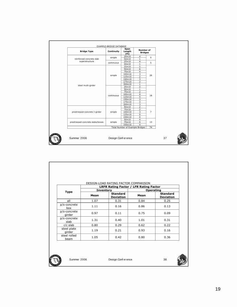
EXAMPLE-BRIDGE DATABASE
Bridge Type Continuity Span
Length (Ft)
Number of Bridges
25±10 4 simple 50±10 1
5
25±10 4 reinforced-concrete slab
superstructure continuous
50±10 1 5
25±10 5 50±10 6 75±10 4 100±10 3 125±10 2 150±10 3 175±10 2
simple
200±10 1
26
25±10 2 50±10 1 75±10 2 100±10 0 125±10 4 150±10 3 175±10 3
steel multi-girder
continuous
200±10 3
18
50±10 2 75±10 2 100±10 3 125±10 0
prestressed-concrete I-girder simple
150±10 0
7
50±10 4 75±10 5 prestressed-concrete slabs/boxes simple 100±10 4
13
Total Number of Example Bridges 74
Summer 2006 Design Conference 38
DESIGN-LOAD RATING FACTOR COMPARISON
LRFR Rating Factor / LFR Rating Factor Inventory Operating Type
Mean Standard Deviation
Mean Standard Deviation
all 1.07 0.31 0.84 0.25 p/s-concrete
box 1.11 0.16 0.86 0.13
p/s-concrete girder
0.97 0.11 0.75 0.09
p/s-concrete slab
1.31 0.40 1.01 0.31
r/c slab 0.80 0.29 0.62 0.22 steel plate
girder 1.19 0.21 0.93 0.16
steel rolled beam 1.05 0.42 0.80 0.36

20
Summer 2006 Design Conference 39
DESIGN-LOAD RATING-FACTOR RATIO COMPARISON
Operating Rating Factor / Inventory Rating Factor LFR LRFR Type
Mean Standard Deviation
Mean Standard Deviation
all 1.68 0.038 1.31 0.059 p/s-concrete
box 1.67 0.005 1.30 0.002
p/s-concrete girders
1.68 0.002 1.30 0.002
p/s-concrete slab
1.67 0.001 1.30 0.001
r/c slab 1.67 0.005 1.29 0.005 steel plate
girder 1.68 0.018 1.31 0.086
steel rolled beam
1.69 0.073 1.31 0.063
Summer 2006 Design Conference 40
SPAN-LENGTH EFFECT
0
0.2
0.4
0.6
0.8
1
1.2
1.4
1.6
1.8
2
0 50 100 150 200
Span Length (ft)
LR
FR
/ L
FR
In
ven
tory
Ra
tin
g R
ati
o
p/s boxes
p/s girders
p/s slabs
r/c slabs
plategirdersrolledbeams

21
Summer 2006 Design Conference 41
OPERATING RATING COMPARISON LRFR Rating / LFR Rating
Legal Loads Type 3 Type 3S2 Type 3-3
Permit Truck Type
Mean Standard Deviation
Mean Standard Deviation
Mean Standard Deviation
Mean Standard Deviation
all 1.17 0.37 1.18 0.37 1.18 0.37 1.14 0.35 p/s-
concrete box
1.14 0.20 1.14 0.20 1.14 0.19 1.14 0.20
p/s-concrete girders
0.99 0.16 1.03 0.17 1.03 0.17 0.96 0.21
p/s-concrete
slab 1.27 0.42 1.27 0.41 1.27 0.41 1.27 0.42
r/c slab 0.83 0.28 0.87 0.33 0.85 0.30 0.83 0.28 steel plate girder
1.42 0.24 1.42 0.26 1.43 0.27 1.36 0.24
steel rolled beam
1.10 0.46 1.10 0.46 1.09 0.46 1.07 0.43
Summer 2006 Design Conference 42
The reliability of the example bridges was The reliability of the example bridges was established through Monte Carlo simulation. established through Monte Carlo simulation. The application of Monte Carlo simulation The application of Monte Carlo simulation
employed for this study compares two employed for this study compares two distributions of values; in this case, load and distributions of values; in this case, load and resistance; and determines a random value resistance; and determines a random value of resistance minus load for a given design of resistance minus load for a given design
criteria, in this case the Strength I limit state criteria, in this case the Strength I limit state for flexure.for flexure.
MONTE CARLO SIMULATIONMONTE CARLO SIMULATION

22
Summer 2006 Design Conference 43
STATISTICS
Parameter Assumed
Distribution
Bias Factor, λ, associated with
LRFD
Coefficient of Variation, V
D, dead load 1.05 0.10 L, live load plus
impact normal
1.30 0.18
R, composite-steel flexural resistance 1.12 0.10
R, reinforced-concrete flexural
resistance 1.12 0.13
R, prestressed-concrete flexural
resistance
lognormal
1.05 0.075
Note: The mean value of a parameter, μ, is equal to the nominal value times the bias factor. The standard deviation, σ, is equal to the coefficient of variation, V, times the mean value.
Summer 2006 Design Conference 44
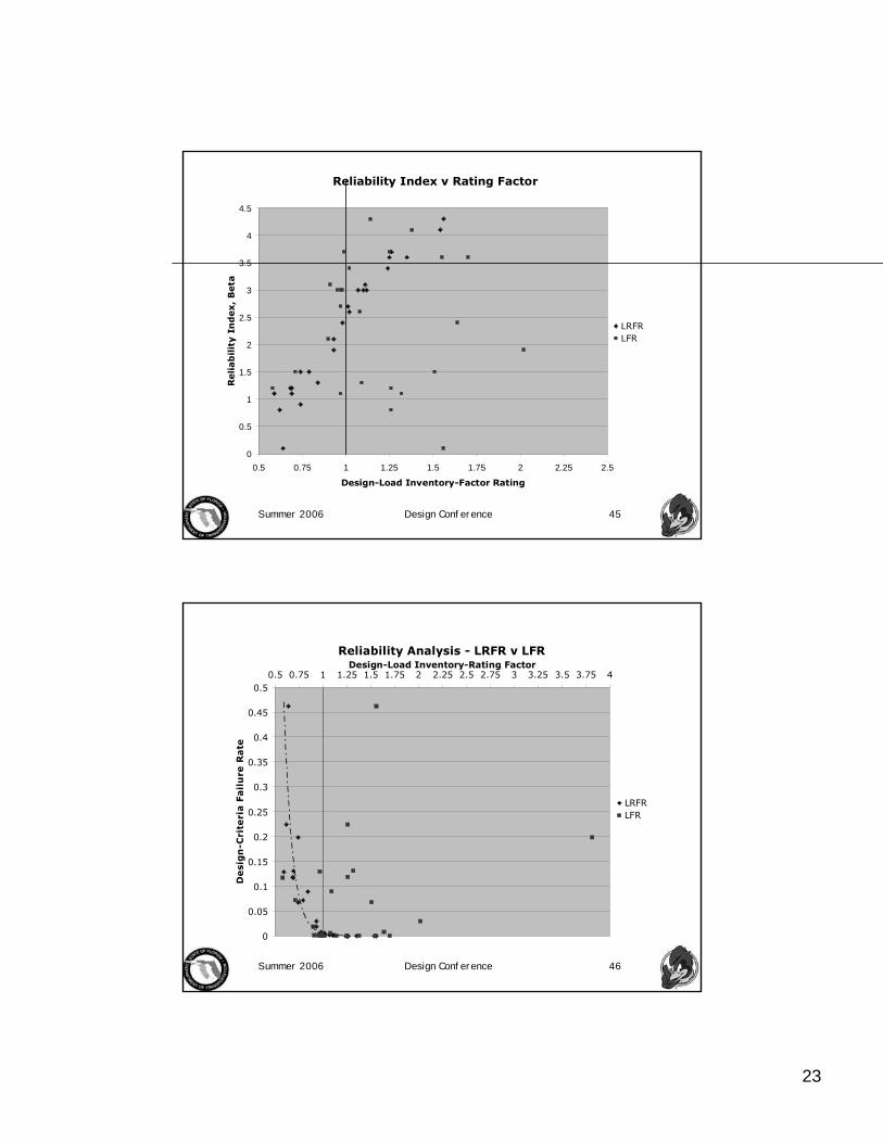
Twenty six of the bridges in the 74 bridge Twenty six of the bridges in the 74 bridge database demonstrated a failure rate of more database demonstrated a failure rate of more than 10 failures out of 1,000,000 simulations than 10 failures out of 1,000,000 simulations
((ββ > about 4.5).> about 4.5).
23
Summer 2006 Design Conference 45
Reliability Index v Rating Factor
0
0.5
1
1.5
2
2.5
3
3.5
4
4.5
0.5 0.75 1 1.25 1.5 1.75 2 2.25 2.5
Design-Load Inventory-Factor Rating
Reliab
ilit
y I
nd
ex,
Beta
LRFRLFR
Summer 2006 Design Conference 46
Reliability Analysis - LRFR v LFR
0
0.05
0.1
0.15
0.2
0.25
0.3
0.35
0.4
0.45
0.50.5 0.75 1 1.25 1.5 1.75 2 2.25 2.5 2.75 3 3.25 3.5 3.75 4
Design-Load Inventory-Rating Factor
De
sig
n-C
rite
ria
Fa
ilu
re R
ate
LRFRLFR
24
Summer 2006 Design Conference 47
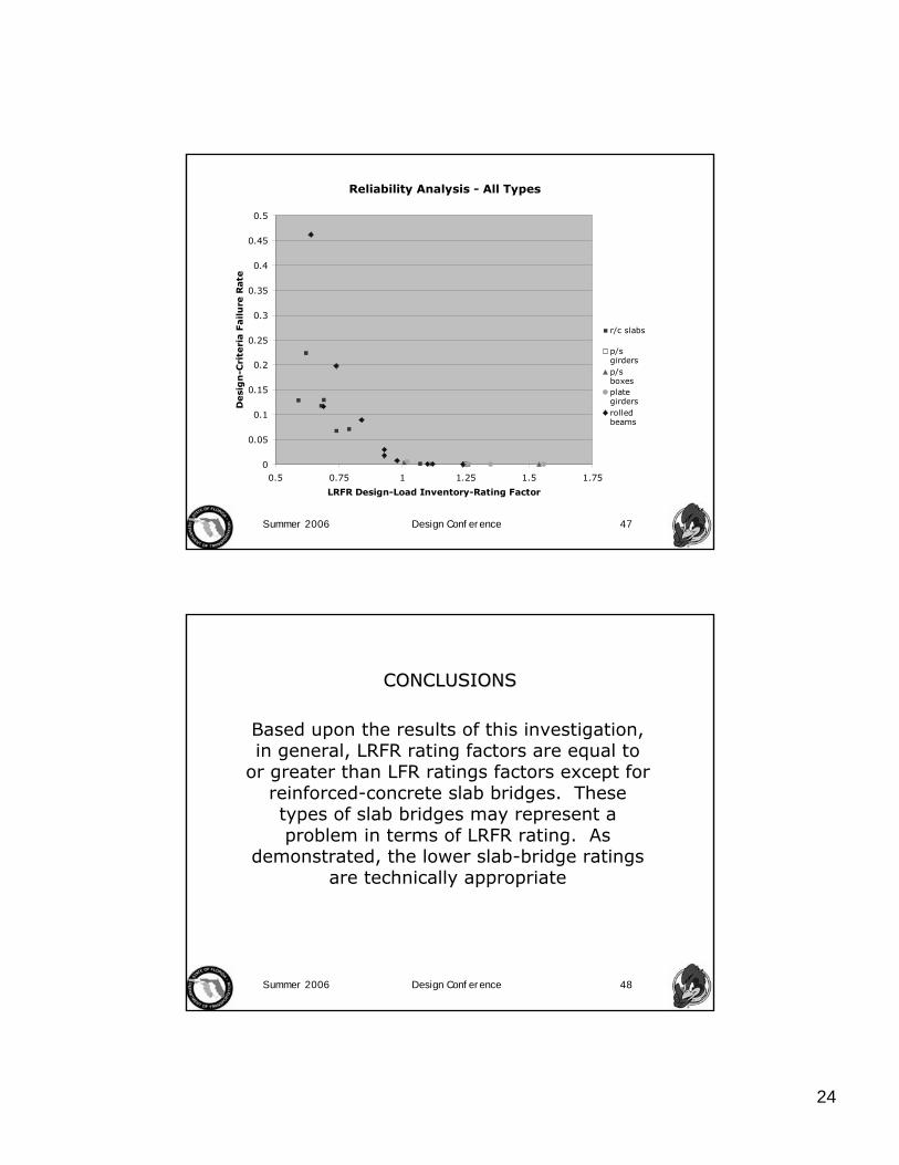
Reliability Analysis - All Types
0
0.05
0.1
0.15
0.2
0.25
0.3
0.35
0.4
0.45
0.5
0.5 0.75 1 1.25 1.5 1.75
LRFR Design-Load Inventory-Rating Factor
Desi
gn
-Cri
teri
a F
ailu
re R
ate
r/c slabs
p/sgirdersp/sboxesplategirdersrolledbeams
Summer 2006 Design Conference 48
Based upon the results of this investigation, in general, LRFR rating factors are equal to
or greater than LFR ratings factors except for reinforced-concrete slab bridges. These types of slab bridges may represent a problem in terms of LRFR rating. As
demonstrated, the lower slab-bridge ratings are technically appropriate
CONCLUSIONSCONCLUSIONS

25
Summer 2006 Design Conference 49
This study suggests that LRFR is technically sound with the LRFR rating factors in good
correlation with the failure rates. LRFR rating factors lower than one demonstrated
relatively high failure rates. LFR ratings did not correlate well. In fact, many bridges with LFR rating factors above one demonstrated
unacceptably high failure rates. This is not to say that the continued use of LFR rating is
necessarily unsafe, just irrational.
Summer 2006 Design Conference 50
Questions about LRFR versus LFR for force effects other than moment and limit states
other than strength are not answered. Nonetheless, the researcher recommends
adoption of the LRFR methodology for rating bridges. Assuming the LRFR calibration
process is sound, comparable results should result for other more extensive studies. The service limit states which are uncalibrated
and optional in LRFR need additional thought.
RECOMMENDATIONSRECOMMENDATIONS

26
Summer 2006 Design Conference 51
If the diminished range between inventory If the diminished range between inventory and operating ratings shown in Table 4 is not and operating ratings shown in Table 4 is not acceptable from an operational standpoint, acceptable from an operational standpoint, them the target reliability index, them the target reliability index, ββTT, for the , for the
operating rating in LRFR should be reoperating rating in LRFR should be re--evaluated. Decreasing evaluated. Decreasing ββTT, will increase this , will increase this
range.range.
Summer 2006 Design Conference 52
Part 2Part 2
back toback to
FDOT RATING POLICIES FDOT RATING POLICIES & PROCEDURES& PROCEDURES
27
Summer 2006 Design Conference 53
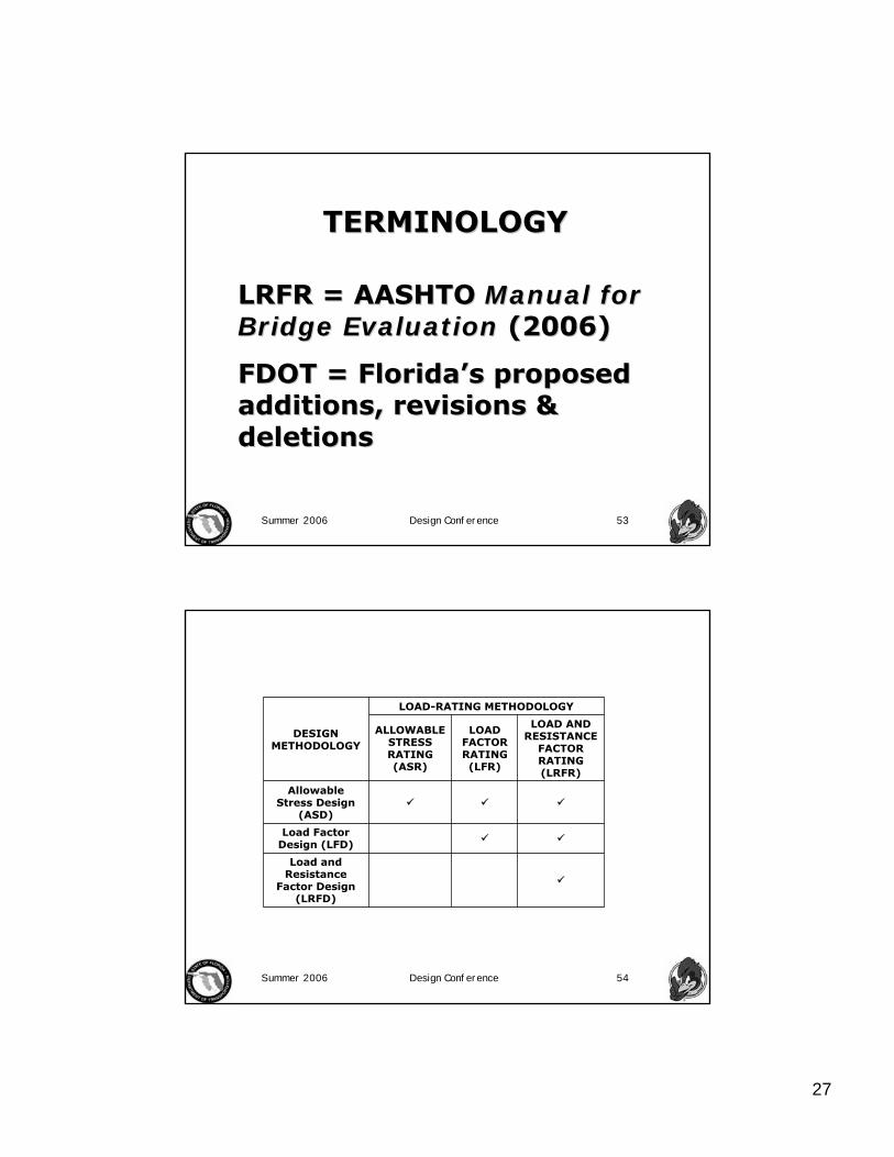
TERMINOLOGYTERMINOLOGY
LRFR = AASHTO LRFR = AASHTO Manual for Manual for Bridge EvaluationBridge Evaluation (2006)(2006)
FDOT = FloridaFDOT = Florida’’s proposed s proposed additions, revisions & additions, revisions & deletionsdeletions
Summer 2006 Design Conference 54
Load and Resistance
Factor Design (LRFD)
Load Factor Design (LFD)
Allowable Stress Design
(ASD)
LOAD AND RESISTANCE
FACTOR RATING (LRFR)
LOAD FACTOR RATING (LFR)
ALLOWABLE STRESS RATING (ASR)
LOAD-RATING METHODOLOGY
DESIGN METHODOLOGY
28
Summer 2006 Design Conference 55
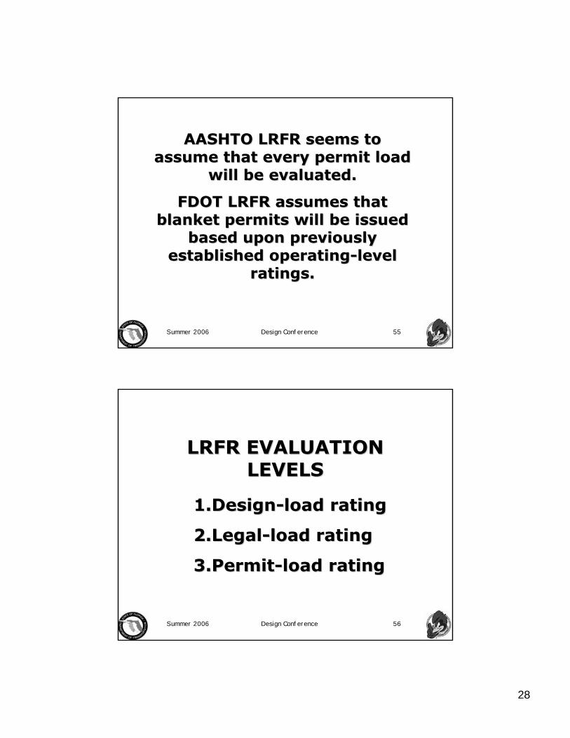
AASHTO LRFR seems to AASHTO LRFR seems to assume that every permit load assume that every permit load
will be evaluated.will be evaluated.
FDOT LRFR assumes that FDOT LRFR assumes that blanket permits will be issued blanket permits will be issued
based upon previously based upon previously established operatingestablished operating--level level
ratings.ratings.
Summer 2006 Design Conference 56
LRFR EVALUATION LRFR EVALUATION LEVELSLEVELS
1.1.DesignDesign--load ratingload rating
2.2.LegalLegal--load ratingload rating
3.3.PermitPermit--load ratingload rating

29
Summer 2006 Design Conference 57
FDOT EVALUATION FDOT EVALUATION LEVELSLEVELS
1.1.DesignDesign--load & load & permitpermit--load ratingload rating
2.2.LegalLegal--load ratingload rating
Summer 2006 Design Conference 58
LRFR RATING LEVELSLRFR RATING LEVELS
•• Inventory Inventory –– ββ = 3.5 = 3.5 ((represents LRFD represents LRFD designdesign))
•• Operating Operating –– ββ = 2.5 = 2.5 ((represents represents traditional operatingtraditional operating))

30
Summer 2006 Design Conference 59
__0108 3__0108 3--span channel unitspan channel unit
__0108 __0108 -- 44--span unitspan unitContinuous Continuous
prestressedprestressed concrete concrete spliced girderspliced girder
__4094__4094
(edge)(edge)__0091__0091
Continuous flat slabsContinuous flat slabs
__0081__0081
__0196 __0196 -- 14 14 wbwb
__0196 __0196 -- 7 7 wbwb
__0196 __0196 -- 3 3 wbwb
__0057 __0057 -- span 1 & 4span 1 & 4
__0057 __0057 -- span 2 & 3span 2 & 3
__0052__0052
__0074__0074
SimpleSimple--span span prestressedprestressed concrete concrete beam simplebeam simple--spansspans
FDOTFDOTSDRSDRLEAPLEAPCORVENCORVENBRIDGEBRIDGETYPETYPE
Florida Florida Database Database
of of Concrete Concrete BridgesBridges
analysis analysis complete & complete & results in results in spreadsheetspreadsheet
analysis analysis completecomplete
Summer 2006 Design Conference 60
____________ContinuousContinuous
____________SimpleSimpleTub Tub GirderGirder
__0323__0323ContinuousContinuous
__0620__0620SimpleSimplePlate Plate GirderGirder
RefinedRefinedSimpleSimple
AnalysisAnalysisBridge Bridge NumberNumber
Span TypeSpan TypeBridge Bridge TypeType
FloridaFlorida’’s Database of Steel Bridgess Database of Steel Bridges
31
Summer 2006 Design Conference 61
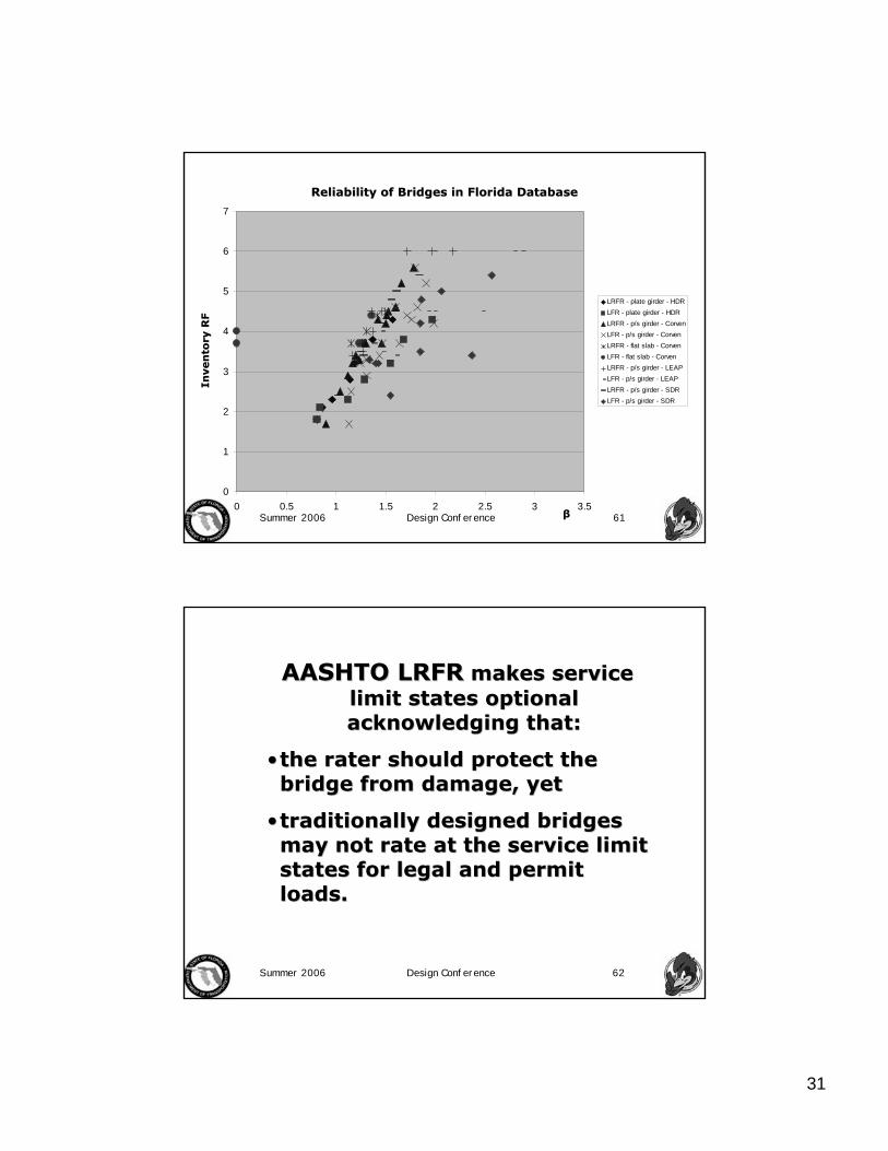
0
1
2
3
4
5
6
7
0 0.5 1 1.5 2 2.5 3 3.5
LRFR - plate girder - HDRLFR - plate girder - HDRLRFR - p/s girder - CorvenLFR - p/s girder - CorvenLRFR - flat slab - CorvenLFR - flat slab - CorvenLRFR - p/s girder - LEAPLFR - p/s girder - LEAPLRFR - p/s girder - SDRLFR - p/s girder - SDR
Reliability of Bridges in Florida DatabaseReliability of Bridges in Florida DatabaseIn
ven
tory
RF
Inven
tory
RF
ββ
Summer 2006 Design Conference 62
AASHTO LRFRAASHTO LRFR makes service makes service limit states optional limit states optional acknowledging that:acknowledging that:
•• the rater should protect the the rater should protect the bridge from damage, yetbridge from damage, yet
•• traditionally designed bridges traditionally designed bridges may not rate at the service limit may not rate at the service limit states for legal and permit states for legal and permit loads.loads.

32
Summer 2006 Design Conference 63
FDOT LRFRFDOT LRFR calibrates the calibrates the service limit states so that:service limit states so that:
•• the rater protects the bridge the rater protects the bridge from damage, yetfrom damage, yet
•• traditionally designed bridges traditionally designed bridges will not rate so poorly at the will not rate so poorly at the service limit states for legal and service limit states for legal and permit loads.permit loads.
Summer 2006 Design Conference 64
The LRFR Equation The LRFR Equation (LRFR (LRFR EqEq 66--1)1)
( )( ) ( )( ) ( )( )( )( )IMLL
PDWDCCRF
L
PDWDC
+±−−
=γ
γγγ
wherewhere
nsc RC φφφ=
RfC =
for strengthfor strength
for servicefor service

33
Summer 2006 Design Conference 65
CONCEPT OF A NOTIONAL CONCEPT OF A NOTIONAL LIVE LOAD MODELLIVE LOAD MODEL
A load model which does not A load model which does not necessarily necessarily ““looklook”” like a truck, like a truck,
but which produces force but which produces force effects (for example, moments effects (for example, moments
& shears) representative of & shears) representative of actual trucks.actual trucks.
Summer 2006 Design Conference 66
Design TandemTwo 25.0 KIP axles spaced 4.0 FT apart
Design Lane LoadUniformly distributed load of 0.64 KLF
Design Vehicular Live LoadsDesign Vehicular Live LoadsDesign TruckDesign Truck

34
Summer 2006 Design Conference 67
Application of Design Vehicular LLApplication of Design Vehicular LLLRFD 3.6.1.2.1 and 3.6.1.3.1LRFD 3.6.1.2.1 and 3.6.1.3.1
Designation: HLDesignation: HL--9393Service and Strength Limit States:Service and Strength Limit States:
Design Truck Design Truck OROR Design TandemDesign TandemANDAND
Design Lane LoadDesign Lane Load
The design lane load is The design lane load is notnot interrupted for the interrupted for the design truck or design tandemdesign truck or design tandem. Interruption is Interruption is needed only where pattern loadings are used to needed only where pattern loadings are used to produce maximum effects.produce maximum effects.
Summer 2006 Design Conference 68
Comparison of LRFD Notional v. HS20Comparison of LRFD Notional v. HS20The notional model produces live load moments and shears The notional model produces live load moments and shears significantly greater than those caused by the HS20 loading significantly greater than those caused by the HS20 loading
especially for longer spans.especially for longer spans.

35
Summer 2006 Design Conference 69
Justification for New LLJustification for New LLNew New ““notionalnotional”” live load model simulates the shear and live load model simulates the shear and
moment effects of a group of moment effects of a group of ““exclusionexclusion”” vehicles currently vehicles currently allowed to routinely travel on highways in various states.allowed to routinely travel on highways in various states.
Summer 2006 Design Conference 70
EFFECT OF SUPERPOSITION OF EFFECT OF SUPERPOSITION OF VEHICLES & LANE LOAD VEHICLES & LANE LOAD
•• Short spans governed by wheels Short spans governed by wheels –– lane lane load has little effect,load has little effect,
•• Long spans governed by the lane load Long spans governed by the lane load ––the vehicle has little effect, butthe vehicle has little effect, but
•• Intermediate length spans Intermediate length spans –– the lane the lane load amplifies the vehicle effect load amplifies the vehicle effect (without specifying a (without specifying a ““supersuper--legallegal””load.load.

36
Summer 2006 Design Conference 71
Therefore, the HLTherefore, the HL--93 93 rating factor represents a rating factor represents a ratio of the entire effect ratio of the entire effect
(in other words, the (in other words, the governing vehicle and the governing vehicle and the lane) not just the vehicle!lane) not just the vehicle!
Summer 2006 Design Conference 72
The intent of the superposition The intent of the superposition explains the application of the explains the application of the
dynamic load allowance (IM) to dynamic load allowance (IM) to the vehicle force effects only.the vehicle force effects only.
37
Summer 2006 Design Conference 73
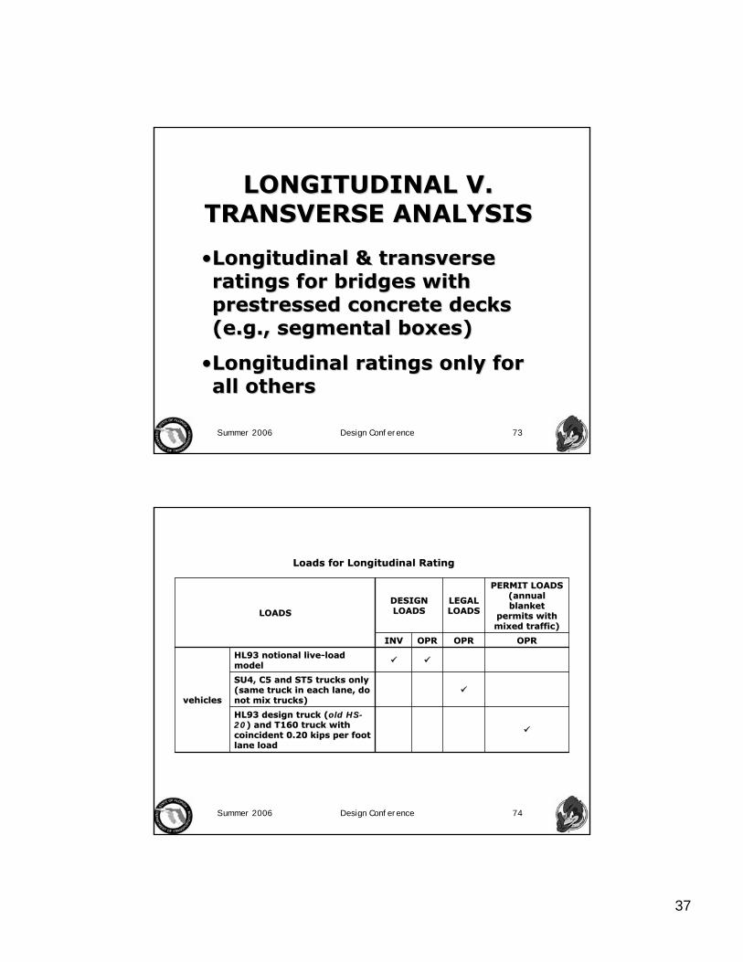
LONGITUDINAL V. LONGITUDINAL V. TRANSVERSE ANALYSIS TRANSVERSE ANALYSIS
••Longitudinal & transverse Longitudinal & transverse ratings for bridges with ratings for bridges with prestressedprestressed concrete decks concrete decks (e.g., segmental boxes)(e.g., segmental boxes)
••Longitudinal ratings only for Longitudinal ratings only for all othersall others
Summer 2006 Design Conference 74
HL93 design truck (HL93 design truck (old HSold HS--2020) and T160 truck with ) and T160 truck with coincident 0.20 kips per foot coincident 0.20 kips per foot lane loadlane load
SU4, C5 and ST5 trucks only SU4, C5 and ST5 trucks only (same truck in each lane, do (same truck in each lane, do not mix trucks)not mix trucks)
HL93 notional liveHL93 notional live--load load modelmodel
vehiclesvehicles
OPROPROPROPROPROPRINVINV
PERMIT LOADS PERMIT LOADS (annual (annual blanket blanket
permits with permits with mixed traffic)mixed traffic)
LEGAL LEGAL LOADSLOADS
DESIGN DESIGN LOADSLOADSLOADSLOADS
Loads for Longitudinal RatingLoads for Longitudinal Rating

38
Summer 2006 Design Conference 75
T160 in one lane and HL93 T160 in one lane and HL93 design truck or design design truck or design tandem without coincident tandem without coincident design lane load in the other design lane load in the other laneslanes
SU4, C5, ST5 and HL93 truck SU4, C5, ST5 and HL93 truck or tandem (same truck in or tandem (same truck in each lane, do not mix each lane, do not mix trucks)trucks)
HL93 truck or tandem HL93 truck or tandem without coincident lane loadwithout coincident lane load
vehiclesvehicles
OPROPROPROPROPROPRINVINV
PERMIT PERMIT LOADS LOADS (annual (annual blanket blanket permits permits
with with mixed mixed traffic)traffic)
LEGAL LEGAL LOADSLOADS
DESIGN DESIGN LOADSLOADSLOADSLOADS
Loads for Transverse Rating Loads for Transverse Rating
Summer 2006 Design Conference 76
1.001.001.001.001.001.00Service IService I
0.750.75330.800.80331.001.001.001.00Service IIIService IIIP/CP/C
1.001.00nana1.001.001.001.00Service IService IR/CR/C
1.001.001.301.301.001.001.301.301.001.001.001.00Service IIService IISteelSteel
1.351.3522nana1.501.501.251.25Strength IIStrength II
nana1.351.35111.351.351.751.751.501.501.251.25Strength IStrength IAll All BridgesBridges
LLLL
OPROPRDWDWDCDC
OPROPRINVINV
PERMIT PERMIT LOADLOAD
LEGAL LEGAL LOADLOAD
DESIGN DESIGN LOADLOAD
LIVE LOADLIVE LOADDEAD DEAD LOADSLOADSLIMITLIMIT--STATE STATE
LOAD LOAD COMBINATIONSCOMBINATIONS
BRIDGE BRIDGE TYPETYPE
11For all traffic volumesFor all traffic volumes22For all types and frequencies of permit For all types and frequencies of permit 33For longitudinal analysis of postFor longitudinal analysis of post--tensioned bridges use striped lanestensioned bridges use striped lanes
LimitLimit--State Load CombinationsState Load Combinations (dead load + live load)(dead load + live load)
39
Summer 2006 Design Conference 77
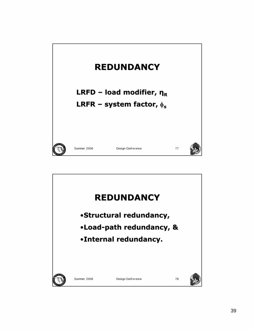
REDUNDANCYREDUNDANCY
LRFD LRFD –– load modifier, load modifier, ηηRR
LRFR LRFR –– system factor, system factor, φφss
Summer 2006 Design Conference 78
REDUNDANCYREDUNDANCY
••Structural redundancy,Structural redundancy,
••LoadLoad--path redundancy, &path redundancy, &
••Internal redundancy.Internal redundancy.
40
Summer 2006 Design Conference 79
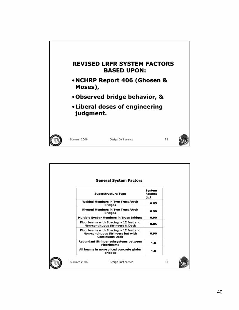
REVISED LRFR SYSTEM FACTORS REVISED LRFR SYSTEM FACTORS BASED UPON:BASED UPON:
••NCHRP Report 406 (NCHRP Report 406 (GhosenGhosen & & Moses),Moses),
••Observed bridge behavior, &Observed bridge behavior, &
••Liberal doses of engineering Liberal doses of engineering judgment.judgment.
Summer 2006 Design Conference 80
0.900.90FloorbeamsFloorbeams with Spacing > 12 feet and with Spacing > 12 feet and
NonNon--continuous Stringers but with continuous Stringers but with Continuous DeckContinuous Deck
1.01.0All beams in nonAll beams in non--spliced concrete girder spliced concrete girder bridgesbridges
1.01.0Redundant Stringer subsystems between Redundant Stringer subsystems between FloorbeamsFloorbeams
0.850.85FloorbeamsFloorbeams with Spacing > 12 feet and with Spacing > 12 feet and NonNon--continuous Stringers & Deckcontinuous Stringers & Deck
0.900.90Multiple Multiple EyebarEyebar Members in Truss BridgesMembers in Truss Bridges
0.900.90Riveted Members in Two Truss/Arch Riveted Members in Two Truss/Arch BridgesBridges
0.850.85Welded Members in Two Truss/Arch Welded Members in Two Truss/Arch BridgesBridges
System System Factors Factors ((φφss))
Superstructure TypeSuperstructure Type
General System FactorsGeneral System Factors
41
Summer 2006 Design Conference 81
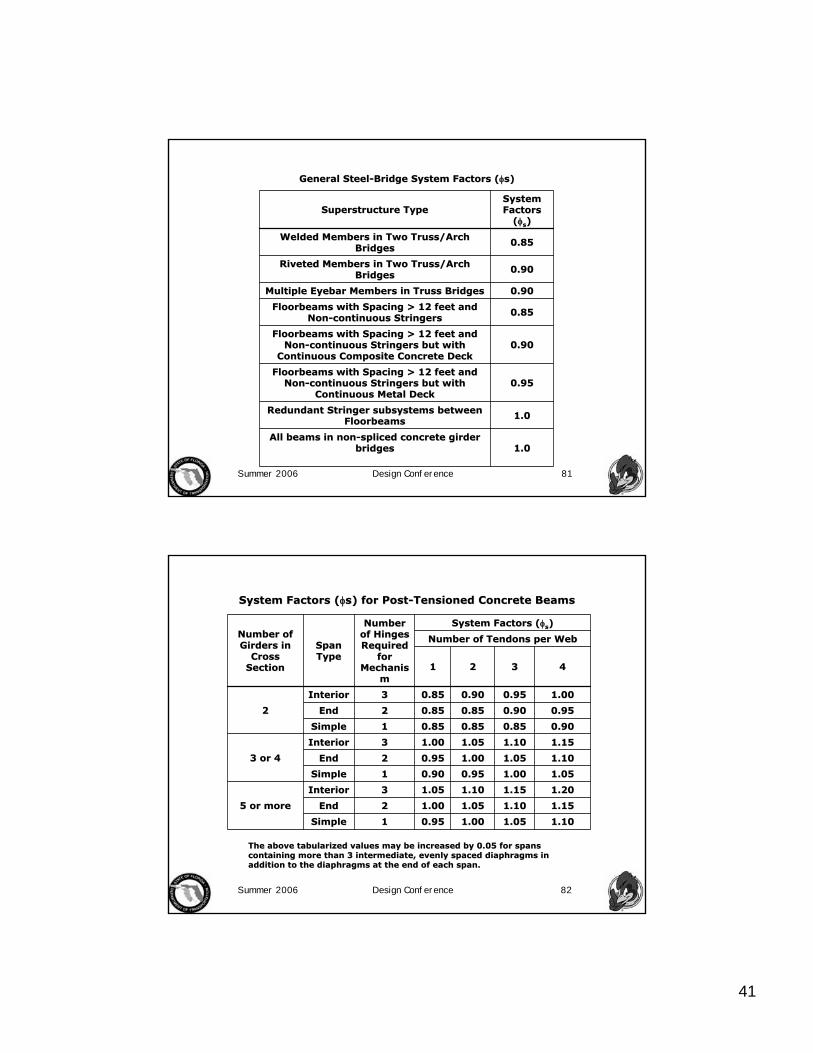
1.01.0All beams in nonAll beams in non--spliced concrete girder spliced concrete girder
bridgesbridges
0.950.95FloorbeamsFloorbeams with Spacing > 12 feet and with Spacing > 12 feet and
NonNon--continuous Stringers but with continuous Stringers but with Continuous Metal DeckContinuous Metal Deck
0.900.90FloorbeamsFloorbeams with Spacing > 12 feet and with Spacing > 12 feet and
NonNon--continuous Stringers but with continuous Stringers but with Continuous Composite Concrete DeckContinuous Composite Concrete Deck
1.01.0Redundant Stringer subsystems between Redundant Stringer subsystems between FloorbeamsFloorbeams
0.850.85FloorbeamsFloorbeams with Spacing > 12 feet and with Spacing > 12 feet and NonNon--continuous Stringerscontinuous Stringers
0.900.90Multiple Multiple EyebarEyebar Members in Truss BridgesMembers in Truss Bridges
0.900.90Riveted Members in Two Truss/Arch Riveted Members in Two Truss/Arch BridgesBridges
0.850.85Welded Members in Two Truss/Arch Welded Members in Two Truss/Arch BridgesBridges
System System Factors Factors
((φφss))Superstructure TypeSuperstructure Type
General SteelGeneral Steel--Bridge System Factors (Bridge System Factors (φφs)s)
Summer 2006 Design Conference 82
1.101.101.051.051.001.000.950.9511SimpleSimple
1.151.151.101.101.051.051.001.0022EndEnd
1.201.201.151.151.101.101.051.0533InteriorInterior
5 or more5 or more
1.051.051.001.000.950.950.900.9011SimpleSimple
1.101.101.051.051.001.000.950.9522EndEnd
1.151.151.101.101.051.051.001.0033InteriorInterior
3 or 43 or 4
0.900.900.850.850.850.850.850.8511SimpleSimple
0.950.950.900.900.850.850.850.8522EndEnd
1.001.000.950.950.900.900.850.8533InteriorInterior
22
44332211
Number of Tendons per WebNumber of Tendons per Web
System Factors (System Factors (φφss))Number Number of Hinges of Hinges Required Required
for for MechanisMechanis
mm
Span Span TypeType
Number of Number of Girders in Girders in
Cross Cross SectionSection
System Factors (System Factors (φφs) for Posts) for Post--Tensioned Concrete BeamsTensioned Concrete Beams
The above tabularized values may be increased by 0.05 for spans The above tabularized values may be increased by 0.05 for spans containing more than 3 intermediate, evenly spaced diaphragms incontaining more than 3 intermediate, evenly spaced diaphragms inaddition to the diaphragms at the end of each span.addition to the diaphragms at the end of each span.

42
Summer 2006 Design Conference 83
0.950.9511SimpleSimple
1.001.0022EndEnd
1.051.0533InteriorInterior
5 or more5 or more
0.900.9011SimpleSimple
0.950.9522EndEnd
1.001.0033InteriorInterior
3 or 43 or 4
0.850.8511SimpleSimple
0.850.8522EndEnd
0.850.8533InteriorInterior
22
System System FactorsFactors
# of Hinges # of Hinges Required for Required for MechanismMechanism
Span TypeSpan Type
Number of Number of Girders in Girders in
Cross Cross SectionSection
System Factors (System Factors (φφs) for Steel Girder Bridges s) for Steel Girder Bridges
•• The above tabularized values may be increased by 0.10 for spans The above tabularized values may be increased by 0.10 for spans containing containing evenly spaced intermediate diaphragms in addition to the diaphraevenly spaced intermediate diaphragms in addition to the diaphragms at the gms at the end of each span.end of each span.
•• The above tabularized values may be increased by 0.05 for riveteThe above tabularized values may be increased by 0.05 for riveted membersd members
Summer 2006 Design Conference 84
1.101.101.001.000.900.90nana11Statically Statically DeterminDetermin
ateate
1.151.151.101.101.001.000.850.8522End or End or HingeHinge
1.201.201.151.151.051.050.900.9033InteriorInteriorCastCast--inin--
Place Place BalanceBalance
d d CantilevCantilev
erer
1.101.101.001.00nananana11Statically Statically DeterminDetermin
ateate
1.151.151.051.050.950.95nana22End or End or HingeHinge
1.201.201.101.101.001.00nana33InteriorInteriorPrecastPrecastSpanSpan--
byby--Span Span Type B Type B JointsJoints
1.101.101.001.00nananana11Statically Statically DeterminDetermin
ateate
1.151.151.051.050.950.95nana22End or End or HingeHinge
1.201.201.101.101.001.00nana33InteriorInteriorPrecastPrecastSpanSpan--
byby--Span Span Type A Type A JointsJoints
1.101.101.001.000.900.90nana11Statically Statically DeterminDetermin
ateate
1.151.151.101.101.001.000.850.8522End or End or HingeHinge
1.201.201.151.151.051.050.900.9033InteriorInteriorPrecastPrecastBalanceBalance
d d CantilevCantilever Type er Type A JointsA Joints
44332211
No. of Tendons per WebNo. of Tendons per Web
System Factors (System Factors (φφss))# of # of Hinges Hinges
to to FailureFailure
Span Span TypeType
Bridge Bridge TypeType
System Factors (System Factors (φφs) for Posts) for Post--Tensioned Segmental Concrete BridgesTensioned Segmental Concrete Bridges
(For box (For box girder girder bridges bridges with 3 or with 3 or more more webs, webs, table table values values may be may be increased increased by 0.10)by 0.10)

43
Summer 2006 Design Conference 85
These system factors shall apply for These system factors shall apply for flexural and axial effects at the flexural and axial effects at the Strength limit states.Strength limit states.
Higher values than those tabulated Higher values than those tabulated may be considered on a casemay be considered on a case--byby--case case basis with the approval of the basis with the approval of the Department.Department.
System factors need not be less than System factors need not be less than 0.85. In no case shall the system 0.85. In no case shall the system factor exceed 1.25.factor exceed 1.25.
APPLICATION OF SYSTEM APPLICATION OF SYSTEM FACTORSFACTORS
Summer 2006 Design Conference 86
PRECISION OF PRECISION OF RATINGSRATINGS
Is a rating factor of 0.95 Is a rating factor of 0.95 acceptable?acceptable?
How accurate are our How accurate are our models? How precise are models? How precise are they?they?
Is conservatism precise?Is conservatism precise?

44
Summer 2006 Design Conference 87
Part 3Part 3
FUTURE CHALLENGESFUTURE CHALLENGES
Summer 2006 Design Conference 88
EXTREME EVENTS & EXTREME EVENTS & LOAD COMBINATIONSLOAD COMBINATIONS
TurkstraTurkstra’’ss RuleRule
““Bad things do not happen Bad things do not happen all at once.all at once.””
45
Summer 2006 Design Conference 89
SCOURSCOUR
••Not a load, but a change Not a load, but a change in foundation conditionsin foundation conditions
••ClearClear--ware v. ware v. livelive--bed scourbed scour
Summer 2006 Design Conference 90
HURRICANESHURRICANES
•• Buoyancy,Buoyancy,
•• Horizontal wave attack, Horizontal wave attack, oror
•• Combinations of both?Combinations of both?

46
Summer 2006 Design Conference 91
HURRICANESHURRICANES
•• ExtremeExtreme--event, orevent, or
•• Strength limit state?Strength limit state?
Summer 2006 Design Conference 92
LOAD LOAD COMBINATIONS COMBINATIONS
WITH SCOURWITH SCOUR
••Vessel collision & scourVessel collision & scour
••Hurricanes & scourHurricanes & scour
47
Summer 2006 Design Conference 93
SYSTEM PRESERVATIONSYSTEM PRESERVATION
Distribution of Trucks Distribution of Trucks including blanket permits including blanket permits
v. v. LRFD & LRFR LRFD & LRFR
assumed liveassumed live--load modelsload models
Summer 2006 Design Conference 94
SYSTEM PRESERVATIONSYSTEM PRESERVATION
Standard SpecificationsStandard Specifications’’50 to 6050 to 60--year design life year design life
v. v. LRFD SpecificationsLRFD Specifications’’7575--year design life year design life

48
Summer 2006 Design Conference 95
CALIBRATION OF THE CALIBRATION OF THE SERVICE LIMIT STATESSERVICE LIMIT STATES
••Service I,Service I,
••Service II, &Service II, &
••Service IIIService III
Summer 2006 Design Conference 96
THE SERVICE LIMIT STATES THE SERVICE LIMIT STATES GENERALLY GOVERN THE GENERALLY GOVERN THE
PROPORTIONS OF PROPORTIONS OF SUPERSTRUCTURE MEMBERS.SUPERSTRUCTURE MEMBERS.
PositivePositive--moment regions of steel moment regions of steel girders are governed by the girders are governed by the service II load combination.service II load combination.
PrestressedPrestressed concrete members are concrete members are governed by the service I or III governed by the service I or III
load combinations.load combinations.

49
Summer 2006 Design Conference 97
The The LRFD SpecificationsLRFD Specifications& the new & the new Condition Condition Evaluation ManualEvaluation Manual
(including LRFR) are far (including LRFR) are far from perfect and are from perfect and are
works in progress, but works in progress, but they remain the best they remain the best framework for future framework for future
development.development.
Summer 2006 Design Conference 98
QUESTIONS OR COMMENTS?QUESTIONS OR COMMENTS?
Thank you for your attention.Thank you for your attention.
Questions or comments beyond: Questions or comments beyond: [email protected]@ce.udel.edu
FOR STRICT APPLICATION OF FOR STRICT APPLICATION OF FDOTFDOT’’ss PROCEDURES SEE: PROCEDURES SEE:
www.dot.state.fl.uswww.dot.state.fl.us