Embed Size (px)
Citation preview

LRFD Bridge Design Manual Changes
Dave Dahlberg | Bridge Design Manual & Policy Engineer
May 17, 2017
Bridge Office | mndot.gov/bridge
Overview
1) Concrete mix designations
2) Reinforcing bar development and splice lengths
3) Modification to HL‐93 double truck live load
4) Use of Strength IV load combination
5) Wood structures section
6) Design and evaluation for bridge repair projects
7) Integral abutments
8) Standard plan notes
9) Revised plan sheets
10) Other changes
5/17/2017 Bridge Office | mndot.gov/bridge 2

Concrete Mix Designations – BDM 5.1.1
• Historically MnDOT Specs for concrete mixes were prescriptive
• Industry has been moving to performance specifications
• Contractor mix designs began with 2016 MnDOT Specs
5/17/2017 Bridge Office | mndot.gov/bridge 3
Concrete Mix Designations – BDM 5.1.1
5/17/2017 4
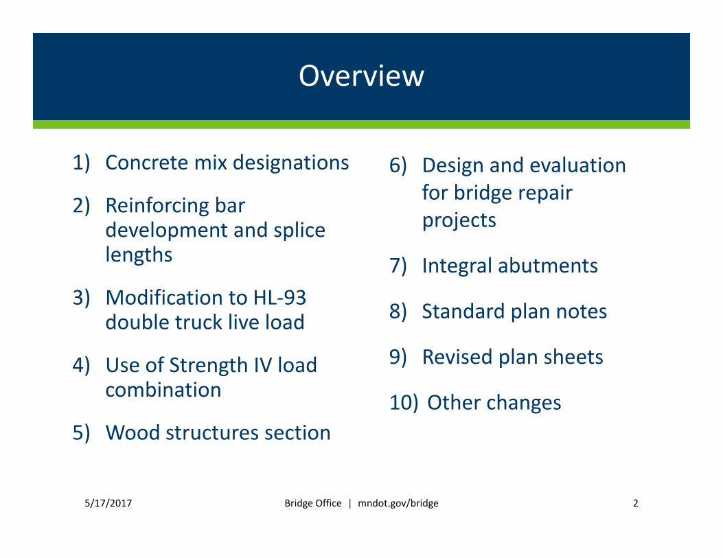
Design Concrete Mix Summary
Location/ElementMnDOT Concrete Mix
Designation
Design Compressive
Strength (ksi)
Maximum
Aggregate Size (in)
Cofferdam seals 1X62 5.0 1
Cast-in-place concrete piles and
spread footing leveling pads1P62 3.0 2
Drilled shafts1X62
3X62
5.0
5.0
1
1
Footings and pile caps 1G52 4.0 1 ½ *
Abutment stems, wingwalls, cast-in-place wall
stems, pier columns, and pier caps3B52 4.0 1 ½ *
Integral abutment diaphragms and
pier continuity diaphragms
Same mix as used in
deck4.0 1
Pretensioned superstructures 1W82 or 3W825.0 – 9.0 at final
4.5 – 7.5 at initial1
Cast-in-place and precast box girders 3JM 6.0 or higher 1
Monolithic decks and slabs3YHPC-M, 3YLCHPC-M
or 3Y42-M4.0 1
Decks and slabs that will receive a 2 inch
concrete wearing course
3YHPC-S, 3YLCHPC-S
or 3Y42-S4.0 1
Barriers, parapets, medians, and sidewalks 3S52 4.0 1
Concrete wearing course 3U17A 4.0 5/8
MSE wall panels, PMBW blocks, and noisewall
panels3Y82 4.0 1
Precast box culverts, arches,
and 3-sided structures3W82 5.0 or higher 1*
In August 2015:• Changes to BDM
5.1.1• Memo to Designers
(2015‐01)
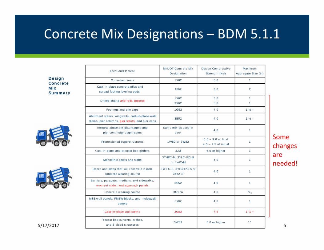
Concrete Mix Designations – BDM 5.1.1
5/17/2017 5
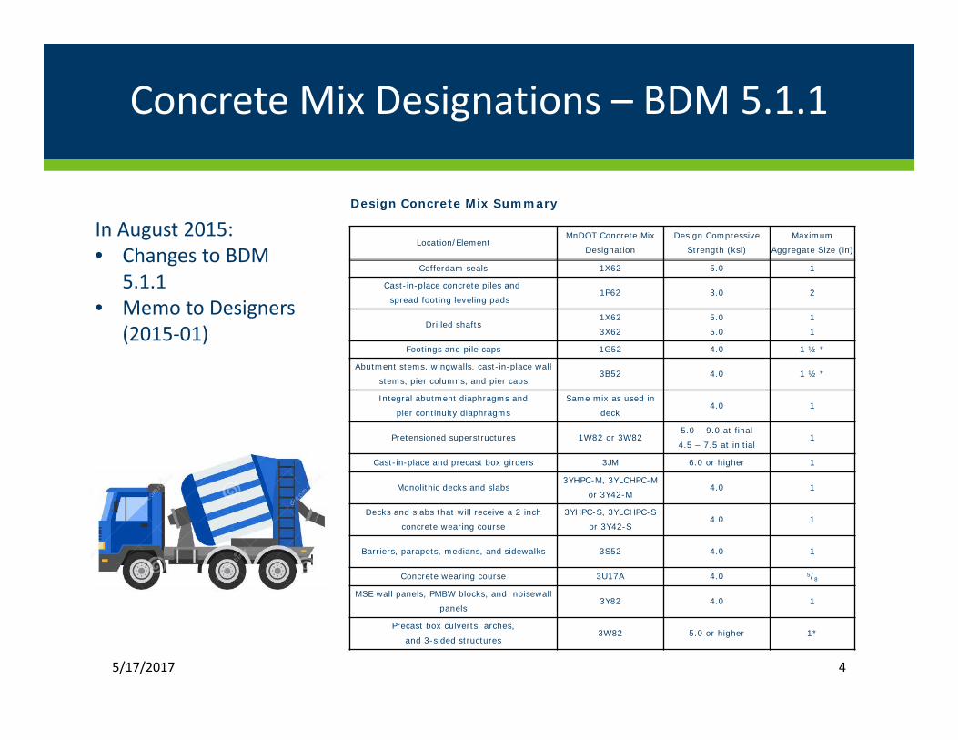
Design Concrete Mix Summary
Location/ElementMnDOT Concrete Mix
Designation
Design Compressive
Strength (ksi)
Maximum
Aggregate Size (in)
Cofferdam seals 1X62 5.0 1
Cast-in-place concrete piles and
spread footing leveling pads1P62 3.0 2
Drilled shafts and rock sockets1X62
3X62
5.0
5.0
1
1
Footings and pile caps 1G52 4.0 1 ½ *
Abutment stems, wingwalls, cast-in-place wall
stems, pier columns, pier struts, and pier caps3B52 4.0 1 ½ *
Integral abutment diaphragms and
pier continuity diaphragms
Same mix as used in
deck4.0 1
Pretensioned superstructures 1W82 or 3W825.0 – 9.0 at final
4.5 – 7.5 at initial1
Cast-in-place and precast box girders 3JM 6.0 or higher 1
Monolithic decks and slabs3YHPC-M, 3YLCHPC-M
or 3Y42-M4.0 1
Decks and slabs that will receive a 2 inch
concrete wearing course
3YHPC-S, 3YLCHPC-S or
3Y42-S4.0 1
Barriers, parapets, medians, and sidewalks,
moment slabs, and approach panels3S52 4.0 1
Concrete wearing course 3U17A 4.0 5/8
MSE wall panels, PMBW blocks, and noisewall
panels3Y82 4.0 1
Cast-in-place wall stems 3G52 4.5 1 ½ *
Precast box culverts, arches,
and 3-sided structures3W82 5.0 or higher 1*
Some changes are needed!
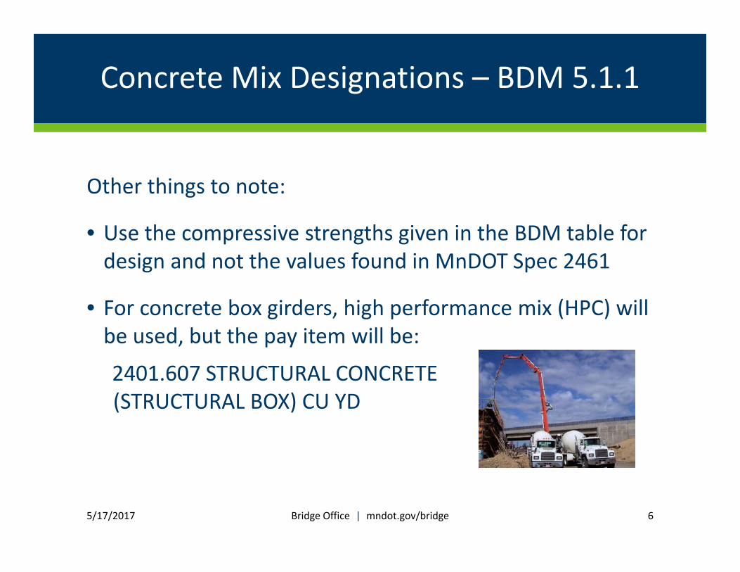
Concrete Mix Designations – BDM 5.1.1
Other things to note:
• Use the compressive strengths given in the BDM table for design and not the values found in MnDOT Spec 2461
• For concrete box girders, high performance mix (HPC) will be used, but the pay item will be:
2401.607 STRUCTURAL CONCRETE(STRUCTURAL BOX) CU YD
5/17/2017 Bridge Office | mndot.gov/bridge 6

Rebar Development and Splice LengthsBDM 5.2.2
Major revisions occurred in 2015 interims of AASHTO LRFD Bridge Design Specs:
• New provisions more complex
• Class C splice length dropped, Class A and Class B retained
• Overall effect:
• Development lengths increased
• Splice length changes less drastic, with some increases and some decreases
5/17/2017 Bridge Office | mndot.gov/bridge 7
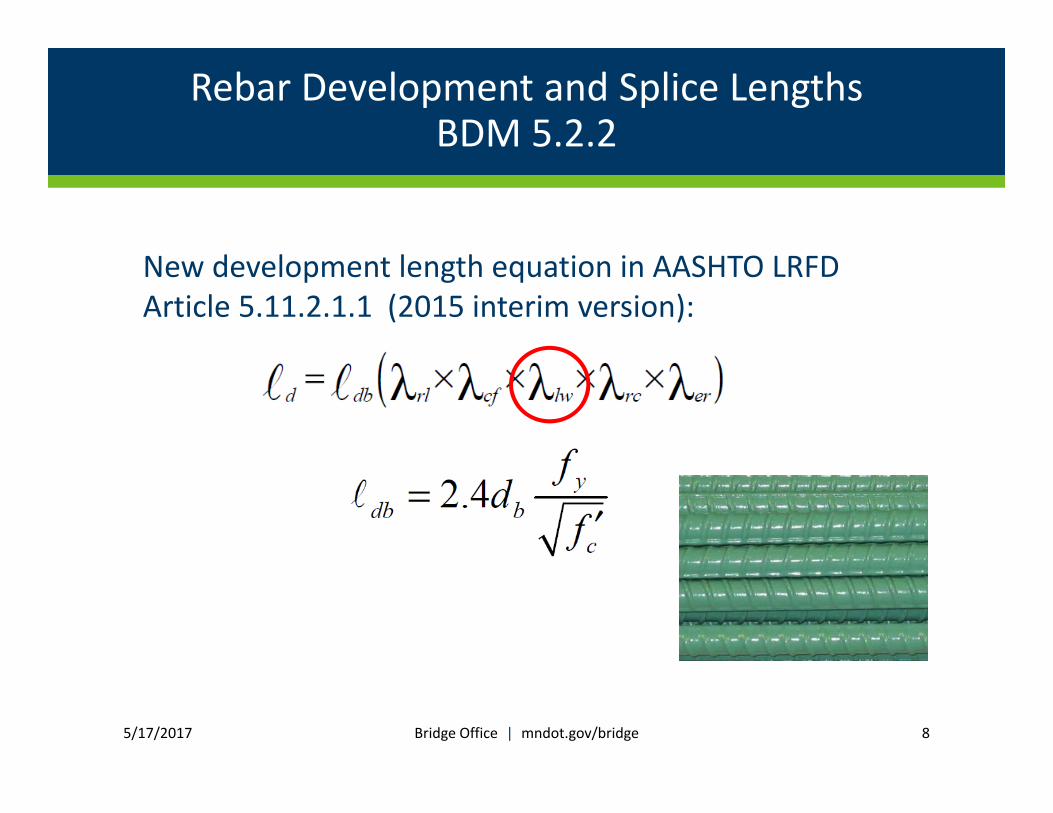
Rebar Development and Splice LengthsBDM 5.2.2
New development length equation in AASHTO LRFD Article 5.11.2.1.1 (2015 interim version):
5/17/2017 Bridge Office | mndot.gov/bridge 8

Rebar Development and Splice LengthsBDM 5.2.2
λlw lightweight concrete factor
• Changed from an equation to 1.3
However…
… it did not stay this way for long!
5/17/2017 Bridge Office | mndot.gov/bridge 9
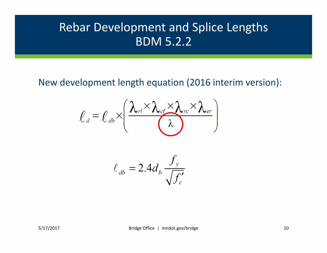
Rebar Development and Splice LengthsBDM 5.2.2
New development length equation (2016 interim version):
5/17/2017 Bridge Office | mndot.gov/bridge 10
Rebar Development and Splice LengthsBDM 5.2.2
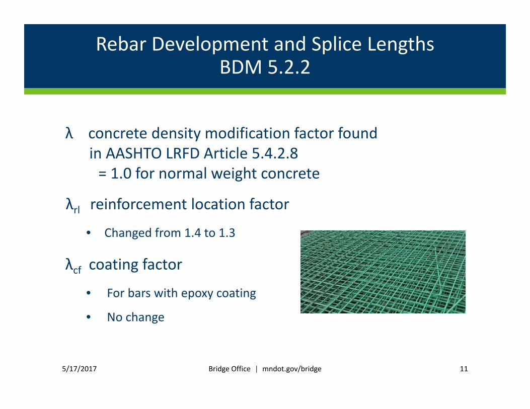
λ concrete density modification factor found in AASHTO LRFD Article 5.4.2.8= 1.0 for normal weight concrete
λrl reinforcement location factor
• Changed from 1.4 to 1.3
λcf coating factor
• For bars with epoxy coating
• No change
5/17/2017 Bridge Office | mndot.gov/bridge 11

Rebar Development and Splice LengthsBDM 5.2.2
λer excess reinforcement factor
• No change
λrc reinforcement confinement factor
• New factor, adds complexity to the calculation
• Dependent on bar diameter, bar spacing, concrete cover, and transverse reinforcement index ktr
5/17/2017 Bridge Office | mndot.gov/bridge 12
Rebar Development and Splice LengthsBDM 5.2.2
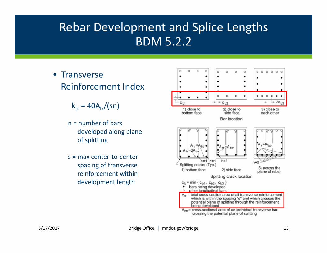
• Transverse Reinforcement Index
ktr = 40Atr/(sn)
n = number of bars developed along plane of splitting
s = max center‐to‐center spacing of transverse reinforcement within development length
5/17/2017 Bridge Office | mndot.gov/bridge 13

Rebar Development and Splice LengthsBDM 5.2.2
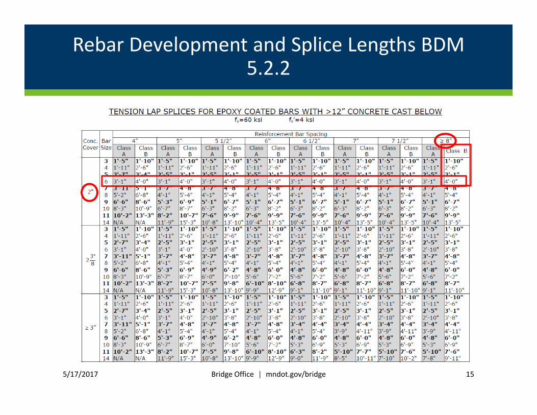
• For simplicity in developing BDM tables, transverse reinforcement index ktr was set equal to zero.
5/17/2017 Bridge Office | mndot.gov/bridge 14
Rebar Development and Splice Lengths BDM 5.2.2
5/17/2017 Bridge Office | mndot.gov/bridge 15
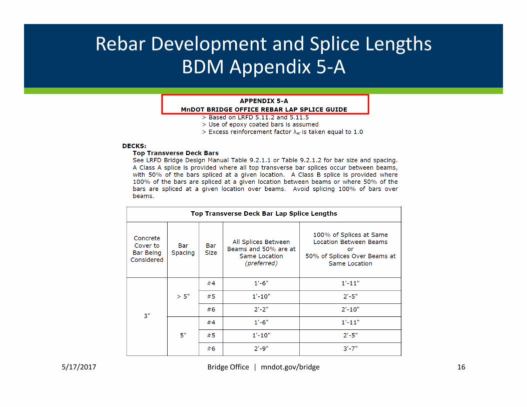
Rebar Development and Splice LengthsBDM Appendix 5‐A
5/17/2017 Bridge Office | mndot.gov/bridge 16
MnDOT Bridge Design Manuals
• In 1996, Mn/DOT Bridge Design Manual had:
136 pages
• In 2017, MnDOT LRFD Bridge Design Manual has:
1154 pages
5/17/2017 Bridge Office | mndot.gov/bridge 17

Modification to HL‐93 Double Truck Live LoadBDM 3.4.1
• AASHTO LRFD Art. 3.6.1.3.1
• For negative moment between points of contraflexure under a uniform load on all spans, and reaction at interior piers only, [apply] 90% of the effect of 2 design trucks spaced a minimum of 50’ between the lead axle of one truck to the rear axle of the other truck, combined with 90% of the effect of the design lane load.
5/17/2017 Bridge Office | mndot.gov/bridge 18
Modification to HL‐93 Double Truck Live LoadBDM 3.4.1
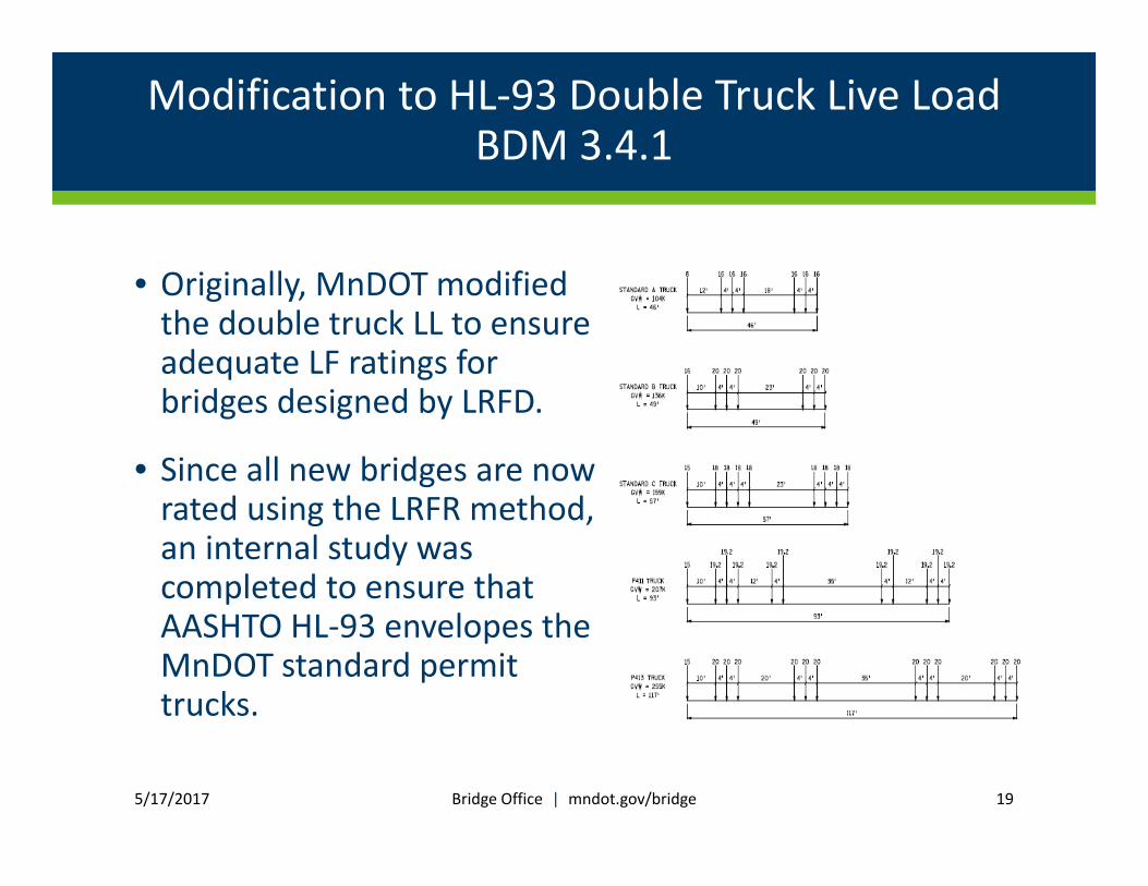
• Originally, MnDOT modified the double truck LL to ensure adequate LF ratings for bridges designed by LRFD.
• Since all new bridges are now rated using the LRFR method, an internal study was completed to ensure that AASHTO HL‐93 envelopes the MnDOT standard permit trucks.
5/17/2017 Bridge Office | mndot.gov/bridge 19
Modification to HL‐93 Double Truck Live LoadBDM 3.4.1
• MnDOT LRFD Bridge Design Manual Art. 3.4.1
• For continuous beam spans, to determine negative moments and reactions at interior piers only:
• For bridges with longest span ≤ 60 ft, apply 125% (HL‐93 double truck with dynamic load allowance plus lane load)
• For bridges with longest span > 60 ft, apply 110% (HL‐93 double truck with dynamic load allowance plus lane load)
• Do not apply LRFD Art. C3.6.1.3.1 double tandem load
• For simple spans, to determine reactions at interior piers only:
• Follow AASHTO LRFD Art. 3.6.1.3.1
5/17/2017 Bridge Office | mndot.gov/bridge 20
Modification to HL‐93 Double Truck Live LoadBDM 3.4.1
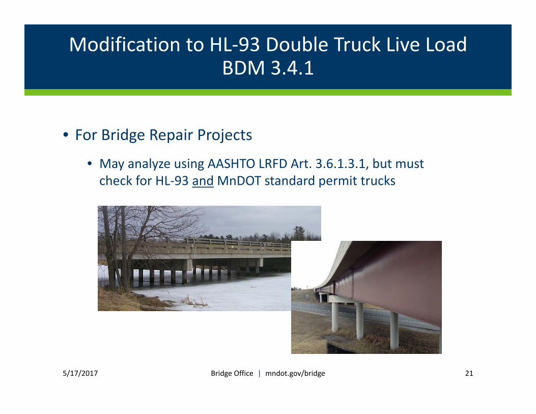
• For Bridge Repair Projects
• May analyze using AASHTO LRFD Art. 3.6.1.3.1, but must check for HL‐93 and MnDOT standard permit trucks
5/17/2017 Bridge Office | mndot.gov/bridge 21

Strength IV Load Combination – BDM 3.1
Found in AASHTO LRFD Article 3.4.1:• Strength IV: Load combination relating to very high
dead load to live load force effect ratios. 1.5DC
(was not calibrated)
• Calibration study was done by Modjeski & Masters
• Some past MnDOT projects used a modified Strength IV: 1.4DC + 1.4LL
5/17/2017 Bridge Office | mndot.gov/bridge 22

Strength IV Load Combination – BDM 3.1
Strength IV: Load combination emphasizing dead load force effects in bridge superstructures.
• For MnDOT projects, use a modified Strength IV load combination, given in AASHTO LRFD Article C3.4.1:
1.4DC + 1.5DW + 1.45LL
• Strength IV only applies to superstructures. It does not apply to investigation of construction stages, substructures, retaining walls, or bearings.
5/17/2017 Bridge Office | mndot.gov/bridge 23
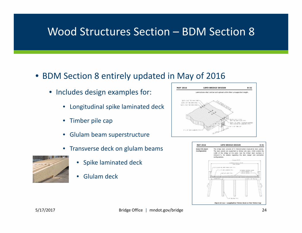
Wood Structures Section – BDM Section 8
• BDM Section 8 entirely updated in May of 2016
• Includes design examples for:
• Longitudinal spike laminated deck
• Timber pile cap
• Glulam beam superstructure
• Transverse deck on glulam beams
• Spike laminated deck
• Glulam deck
5/17/2017 Bridge Office | mndot.gov/bridge 24

Wood Structures Section – BDM Section 8
• Also includes load rating examples for the superstructure elements:
• Longitudinal spike laminated deck
• Glulam beam superstructure
• Transverse deck on glulam beams
• Spike laminated deck
• Glulam deck
5/17/2017 Bridge Office | mndot.gov/bridge 25

Design & Evaluation for Bridge Repair Projects BDM 4.6.2
• Existing bridges requiring repair raise some questions:
• Bridge original design was done per AASHTO Standard Specifications for Highway Bridges. Should Std Specs or LRFD Specs be used for repairs?
5/17/2017 Bridge Office | mndot.gov/bridge 26
?
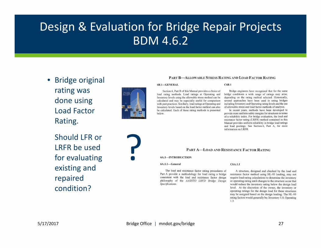
Design & Evaluation for Bridge Repair Projects BDM 4.6.2
• Bridge original rating was done using Load Factor Rating.
Should LFR or LRFR be used for evaluating existing and repaired condition?
5/17/2017 Bridge Office | mndot.gov/bridge 27
?
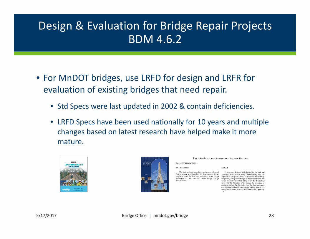
Design & Evaluation for Bridge Repair Projects BDM 4.6.2
• For MnDOT bridges, use LRFD for design and LRFR for evaluation of existing bridges that need repair.
• Std Specs were last updated in 2002 & contain deficiencies.
• LRFD Specs have been used nationally for 10 years and multiple changes based on latest research have helped make it more mature.
5/17/2017 Bridge Office | mndot.gov/bridge 28

Design & Evaluation for Bridge Repair Projects BDM 4.6.2
• Does the entire bridge need to be evaluated?
• For the superstructure, rerating is always required.
• Substructure is typically only rated when significant additional loads will be applied due to the repair
orinspections have noted deterioration or damage to the substructure.
Always use LRFR!
5/17/2017 Bridge Office | mndot.gov/bridge 29
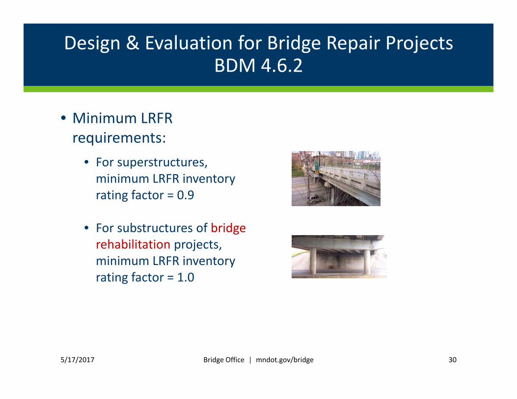
Design & Evaluation for Bridge Repair Projects BDM 4.6.2
• Minimum LRFR requirements:
• For superstructures, minimum LRFR inventory rating factor = 0.9
• For substructures of bridge rehabilitation projects, minimum LRFR inventory rating factor = 1.0
5/17/2017 Bridge Office | mndot.gov/bridge 30

Design & Evaluation for Bridge Repair Projects BDM 4.6.2
• Minimum LRFR requirements (cont’d):• For substructures of major bridge preservation projects where bridge currently has permit restrictions, minimum LRFR inventory rating must be ≥ superstructure inventory rating.
• For substructures of major bridge preservation projects where bridge does not have current permit restrictions, minimum LRFR inventory rating must be ≥ 1.0, but need not exceed the superstructure inventory rating.
5/17/2017 Bridge Office | mndot.gov/bridge 31
Design & Evaluation for Bridge Repair Projects BDM 4.6.2
• If minimum LRFR requirements cannot be met?• Discuss options with Final Design Unit Leader
5/17/2017 Bridge Office | mndot.gov/bridge 32
AASHTO Bridge Design Specifications
5/17/2017 Bridge Office | mndot.gov/bridge 33
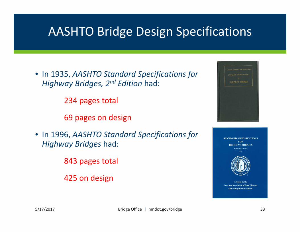
• In 1935, AASHTO Standard Specifications for Highway Bridges, 2nd Edition had:
234 pages total
69 pages on design
• In 1996, AASHTO Standard Specifications for Highway Bridges had:
843 pages total
425 on design

AASHTO Bridge Design Specifications
5/17/2017 Bridge Office | mndot.gov/bridge 34
• Fast forward to 2016
• AASHTO LRFD Bridge Design Specificationshas:
2150 pages
• AASHTO LRFD Bridge Construction Specifications has:
717 pages
Integral Abutments BDM 11.6.2
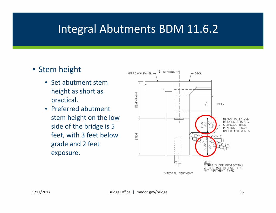
• Stem height• Set abutment stem height as short as practical.
• Preferred abutment stem height on the low side of the bridge is 5 feet, with 3 feet below grade and 2 feet exposure.
5/17/2017 Bridge Office | mndot.gov/bridge 35
Integral Abutments BDM 11.6.2
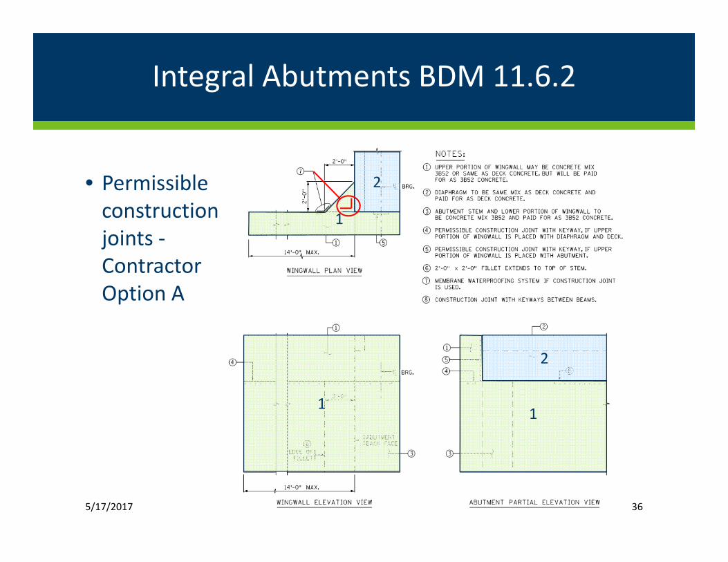
• Permissible construction joints ‐Contractor Option A
5/17/2017 Bridge Office | mndot.gov/bridge 36
1
2
1
1
2
1
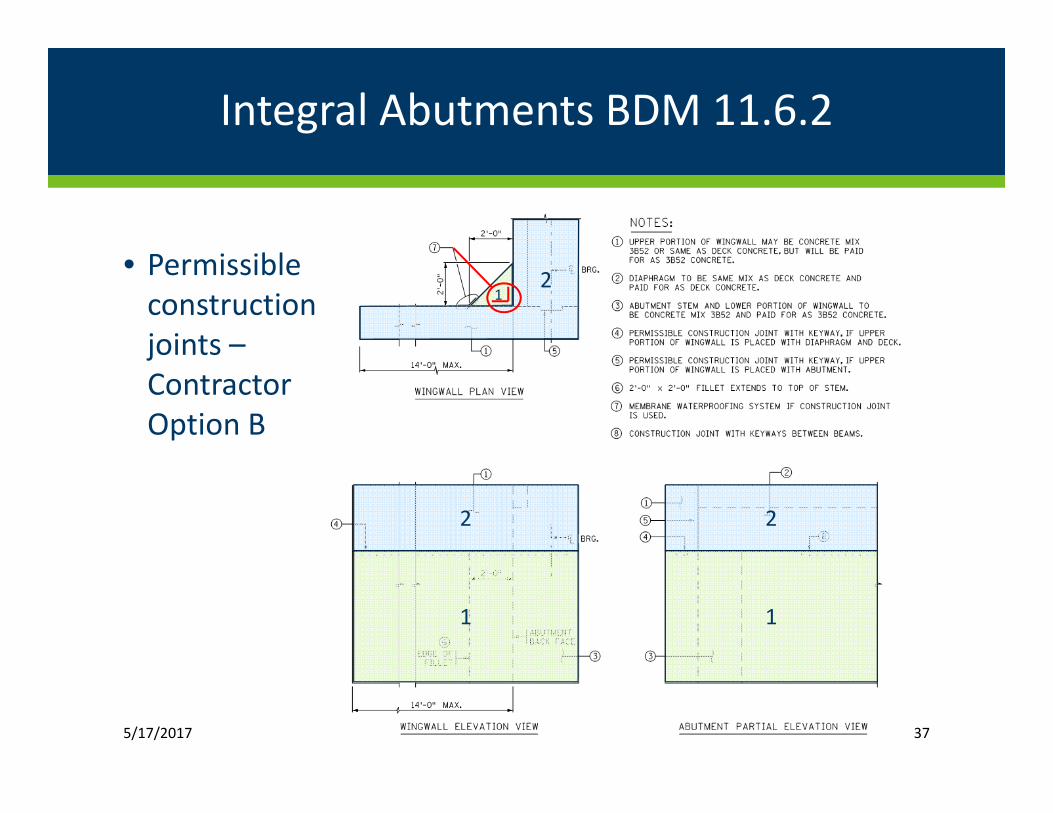
Integral Abutments BDM 11.6.2
• Permissible construction joints –Contractor Option B
5/17/2017 37
1
2
1
2
2
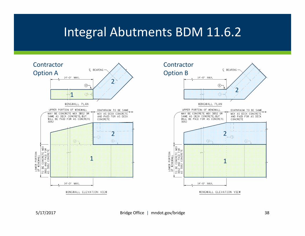
Integral Abutments BDM 11.6.2
5/17/2017 Bridge Office | mndot.gov/bridge 38
1
2
1
2
Contractor Option A
Contractor Option B
21
2

Standard Plan Notes – BDM Appendix 2‐C
• Draft Standard Plan Notes sent out in January 2016
• Numerous changes
plan notes 5‐1‐2017.docx
5/17/2017 Bridge Office | mndot.gov/bridge 39

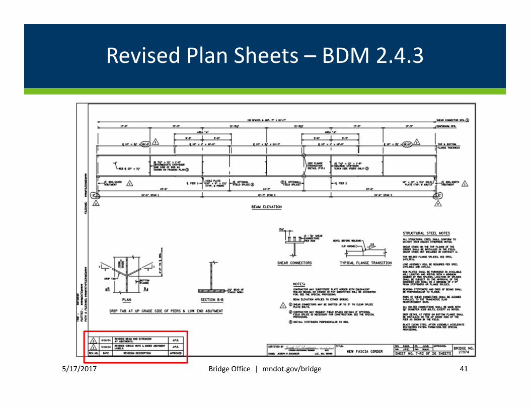
Revised Plan Sheets – BDM 2.4.3
• Clarifying changes were made to the guidance on revised sheets. New guidance is as follows:
1) Make the necessary revisions
2) Add a revision block that includes the revision number within a triangle border, the revision date, a description of the revision, and the initials of the engineer who approved the revision.
5/17/2017 Bridge Office | mndot.gov/bridge 40
Revised Plan Sheets – BDM 2.4.3
5/17/2017 Bridge Office | mndot.gov/bridge 41

Revised Plan Sheets – BDM 2.4.3
5/17/2017 Bridge Office | mndot.gov/bridge 42

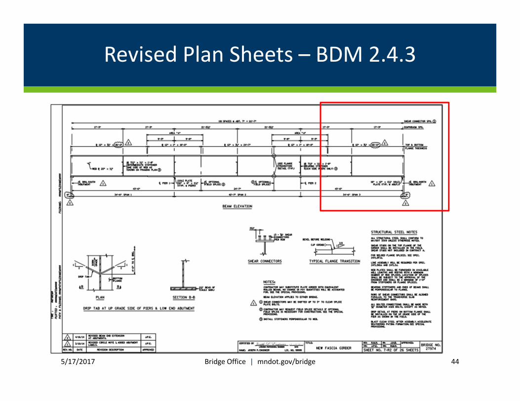
Revised Plan Sheets – BDM 2.4.3
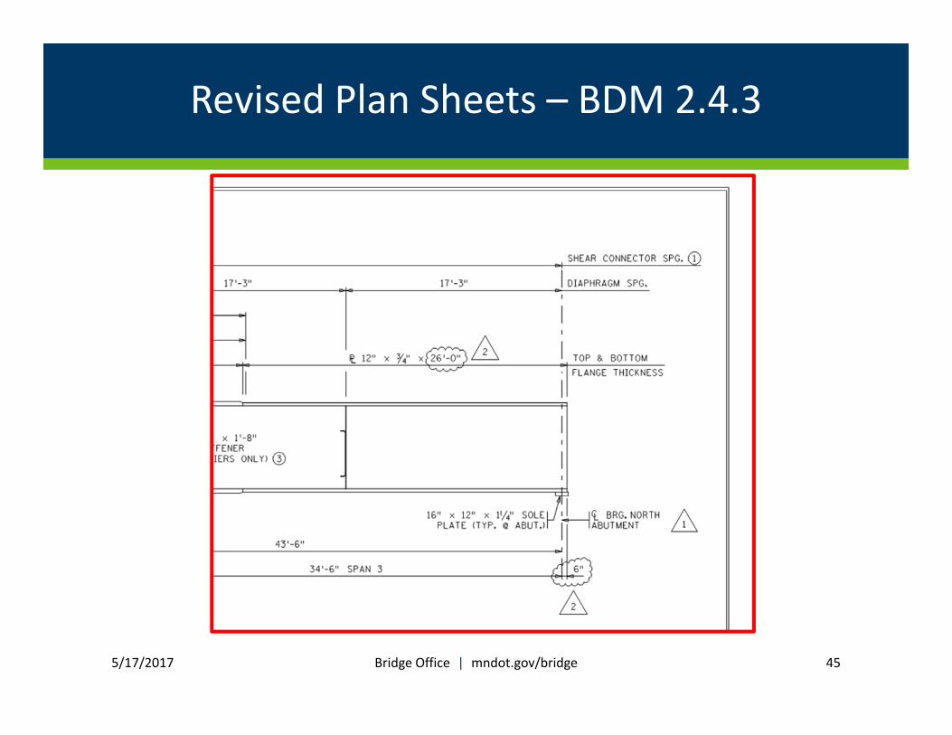
• New guidance (continued):
3) “Cloud” the actual revisions to the sheet and include the revision number within a triangle border next to the “clouded” change. When sheets have been revised multiple times, remove previous revision “clouds”, only “clouding” the current revisions. However, leave previous triangles with their revision numbers in place.
5/17/2017 Bridge Office | mndot.gov/bridge 43
Revised Plan Sheets – BDM 2.4.3
5/17/2017 Bridge Office | mndot.gov/bridge 44
Revised Plan Sheets – BDM 2.4.3
5/17/2017 Bridge Office | mndot.gov/bridge 45
Revised Plan Sheets – BDM 2.4.3
• New guidance (continued):
4) Change the sheet number by placing a “‐R” and the revision number after the original sheet number. For example, revision 1 to sheet 7 will be designated “SHEET NO. 7‐R1”, revision 2 will be designated “SHEET NO. 7‐R2”, etc.
5/17/2017 Bridge Office | mndot.gov/bridge 46

Revised Plan Sheets – BDM 2.4.3
5/17/2017 Bridge Office | mndot.gov/bridge 47

Revised Plan Sheets – BDM 2.4.3
5/17/2017 Bridge Office | mndot.gov/bridge 48
Revised Plan Sheets – BDM 2.4.3
• New guidance (continued):
5) For situations where an additional plan sheet must be inserted as part of the revision, repeat the preceding sheet number with an “A” after it. For example, as part of revision 1 where a sheet needs to be added between sheet 5 and 6, designate the revised sheet as “SHEET NO. 5A‐R1”.
5/17/2017 Bridge Office | mndot.gov/bridge 49

Other BDM Changes
Published:
• Single Slope Barrier (Memo to Designers)
• Deck Overhang Design (Memo to Designers)
5/17/2017 Bridge Office | mndot.gov/bridge 50
Other BDM Changes
Future:
• Section 2 – geometrics, pay items, modifying standards, etc.
• Prestressed beam charts (Type S barrier)
• Section 14 – Bridge Joints and Bearings
• Section 13 – Bridge Railings
• Adhesive anchors
• Section 9 ‐ Decks
• Remove Section 15 on Load Rating (when New Bridge Load Rating Manual is complete)
5/17/2017 Bridge Office | mndot.gov/bridge 51