Embed Size (px)
Citation preview
LP SmartSide Trim & Fascia Application InstructionsStrand & Fiber Substrate190, 440, 540 & 2000 Series
ON SITE STORAGE
• Store off the ground well supported, on a flat well-drained surface. Store products under a roof or separate waterproof covering. (See diagram 1a)
• Additional support may be required to achieve a safe clearance from the ground.
• When the waterproof covering is removed cut all unit banding.
• Keep trim and fascia clean and dry. Inspect prior to installation.
PREPARATION
General Information
1a
A - Corners (Page 6) E - Board and Batten (Page 10)
B - Windows, Doors, Openings (Page 7) F - Mounting Blocks (Page 11)
C - Gable Ends and Barge Rafters (Page 9) G - Exterior Columns (Page 11)
D - Fascia and Rake (Page 9)
A
B GF
E D
C
• There are no National Standards for wood composite substrate trim.
• Louisiana-Pacific’s application instructions describe the minimum requirements needed to assure LP SmartSide limited warranty coverage.
• Trim and fascia installations not in compliance with LP application instructions are prone to reduced service life and products subject to such installation are excluded from coverage under the LP SmartSide limited warranty.
• All exposed wood substrate must be sealed in a manner that prevents moisture intrusion and water build up.
• LP SmartSide trim and fascia can be applied directly over materials such as siding, or fastened directly to structural members up to 24 inches o.c.
• Trim and fascia are not designed for siding; or structural applications and should not be used as a structural member in construction such as a trellis, railing, fencing, decking, decking trim or sills.
• When integrating flashing with a water-resistive barrier (WRB), be sure to follow the WRB installation instructions.
• Install siding products only on walls whose framing members have been kiln dried or air-seasoned to a moisture content of 19% or lower.
• Do not install siding on walls with crooked framing materials.
• Do not install siding over rain-soaked or buckled sheathing.
• Do not use staples.
• Trim must not be in direct contact with masonry, concrete, brick, stone, stucco, or mortar.
1
TRIM & FASCIA 190, 440, 540 & 2000 SERIESPREPARATION
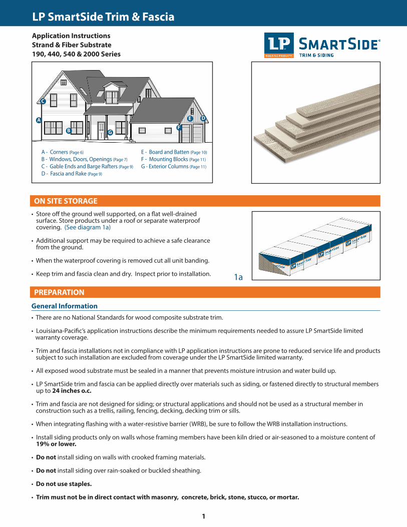
• Minimum 6 inches clearance must be maintained between trim and finished grade. (See diagram 2a)
• Trim applied adjacent to roofs, porches, patios, sidewalks, etc. must have a clearance of at least 1 inch above any surface where water might collect. The surface must be sloped or otherwise designed to provide proper drainage so the trim is at no time directly exposed to standing water. (See diagram 2b)
• A non-corrosive drip-edge must be applied at bottom edge of roofing where it meets the fascia. (See diagrams 2c and 9c)
• In a horizontal brick frieze or band board application where the trim meets the masonry leave a 3/8 inch minimum airspace and flash between the trim and the masonry. (See diagram 2d)
GENERAL REQUIREMENTS (CONTINUED)
• For the cleanest cut and longer blade life, a fine-tooth carbide tipped blade is recommended.
• Trim and fascia are manufactured with a special edge coating which reduces moisture-related issues. Do not rip and/or rout the trim and fascia, as it will leave the edges unprotected. If the trim or fascia materials are ripped you must take special care to prime, paint and seal all exposed wood fiber as described in the finishing section.
• Climb cut the surface of the trim and fascia such that the rotation of the blade cuts downward on the primed or prefinished surface.
• Do not miter trim ends or edges. 45 degree diagonal cuts of trim ends around door and window opening is acceptable, as well as joining. (See diagram 2e)
2a
CUTTING
2b
2c
2d
2e
6” min.
1” min.
Drip-edge
FasciaSub-Fascia
WRB
Siding
3/8” spacewith Z-flashing
Shim
Trim
Brick
3/8” spacewith Z-flashing
General Information (continued)
Cutting
Water-Resistive Barrier
Sheathing
Water-Resistive Barrier
Sheathing
PAINT NEVER NAIL INTO EDGES WITHOUT
PRE-DRILLINGDO NOT MITER
EDGES
DO NOT MITER CUT THE
CORNER JOINT
LP SmartSide Trim & Fascia
2
TRIM & FASCIA 190, 440, 540 & 2000 SERIESPREPARATION
• Properly installed flashing materials will help direct water away from common water collecting areas.
• All flashing material shall be metal or another durable material that under normal outdoor environmental conditions will last for a period of not less than 50 years.
• All flashing materials must have a minimum 4 inch upper leg. Add a 4 inch wide adhesive flashing to flashing legs less than 4 inches.
• Properly integrate flashing with the secondary WRB. Use housewrap, flashing tape, kick-out flashing, step flashing, Z-flashing, drip edge, gutters or other items as needed to maintain the counter-flashing principle.
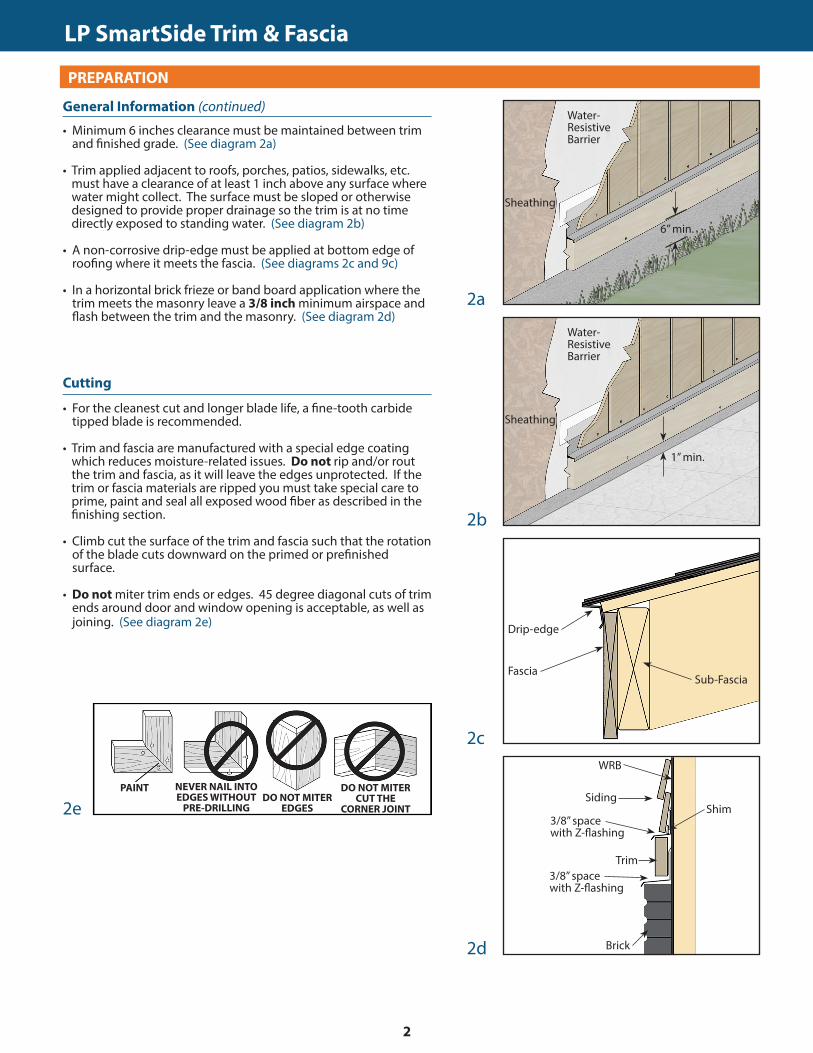
• Install kick-out flashing to direct the water into the gutter. (See diagram 3a)
• Install step flashing that has a minimum 4 inch upper leg. (See diagram 3a)
• Maintain a minimum 1 inch clearance between the end of the gutter and the adjoining wall to allow for proper maintenance of the siding. (See diagram 3b)
• Do not extend the siding or trim into the kick-out flashing or gutter.
• Prime and paint ALL exposed cut edges of siding and trim.
GENERAL REQUIREMENTS (CONTINUED)
• FASTENERS: Minimum 8d (0.113 inch diameter shank), hot-dipped galvanized or stainless steel nail with a 0.270 inch diameter head. Apply and treat nailing errors as specified by these instructions. (See diagram 3c)
• SEALANT: Use an exterior-quality, non-hardening, paintable sealant. Use Class 25 or higher exterior sealant meeting the ASTM C920 Standard for Specification for Elastomeric Joint Sealants. Follow the sealant manufacturer’s instructions for application.
• PAINT: Exterior-quality 100% acrylic latex paint, specially formulated for use on wood and engineered wood substrates, is highly recommended. Semi-gloss or satin finish oil or alkyd paints are acceptable. For flat alkyd paint, please check with the coating manufacturer for their recommendations for use on composite wood siding.
3a
CUTTING
3b
3c
1” min. clearance
Water Run-Off Control
General Application Equipment
WRB
Kick-outFlashing
4” min. step-flashing
1” min. clearance
CONDITION
Snug
Flush
Visible Fiber
Countersunk1/16 - 1/8 inch
Countersunk more than 1/8 inch
CORRECTION
OK
OK
Paint
Apply Sealant
Apply Sealant andre-nail
Shank Diameter ≥ 0.113” Head Diameter ≥ 0.270”
LP SmartSide Trim & Fascia
3
TRIM & FASCIA 190, 440, 540 & 2000 SERIESPREPARATION
• Moisture control and moisture vapor control are critical elements of proper housing design and construction. Check your local building codes for application procedures for handling moisture and water vapor in your area.
• Follow all applicable building code specifications relating to prevention of moisture intrusion into the wall assembly. LP SmartSide trim and fascia is a wood product, and, as with all wood products, must be kept free from excessive moisture. Lack of proper ventilation; exposure to constant or repetitive sources of water such as sprinklers, condensation, inadequate flashing; improper sealing; or failure to follow common building practices that prevent moisture intrusion into the wall system may cause damage, and products subject to such treatment will be excluded from warranty coverage.
• As with all wood products, do not apply engineered wood trim and fascia to a structure having excessive moisture conditions such as drying concrete, plaster, or wet blown cellulose insulation. If such conditions exist, the building should be well ventilated to allow it to dry prior to the application of the trim and fascia.
• Gutters with kick-out flashing and eave drip edge are recommended for control of roof water run off.
GENERAL REQUIREMENTS (CONTINUED)
• Apply nails to meet the specifications in the General Application Equipment section in this document. (See diagram 3c)
• For edge-nailing, all nail holes must be pre-drilled. Do not attempt to edge nail without pre-drilling.
(See diagrams 6e and 6f )
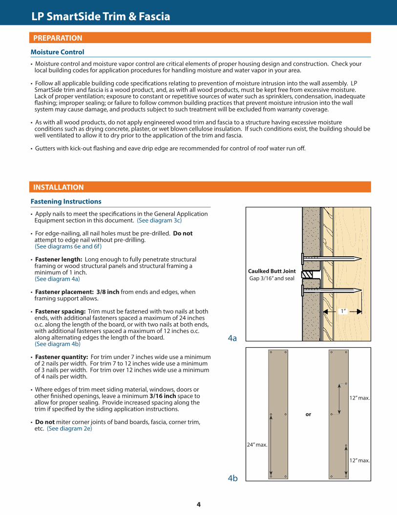
• Fastener length: Long enough to fully penetrate structural framing or wood structural panels and structural framing a minimum of 1 inch.
(See diagram 4a)
• Fastener placement: 3/8 inch from ends and edges, when framing support allows.
• Fastener spacing: Trim must be fastened with two nails at both ends, with additional fasteners spaced a maximum of 24 inches o.c. along the length of the board, or with two nails at both ends, with additional fasteners spaced a maximum of 12 inches o.c. along alternating edges the length of the board.
(See diagram 4b)
• Fastener quantity: For trim under 7 inches wide use a minimum of 2 nails per width. For trim 7 to 12 inches wide use a minimum of 3 nails per width. For trim over 12 inches wide use a minimum of 4 nails per width.
• Where edges of trim meet siding material, windows, doors or other finished openings, leave a minimum 3/16 inch space to allow for proper sealing. Provide increased spacing along the trim if specified by the siding application instructions.
• Do not miter corner joints of band boards, fascia, corner trim, etc. (See diagram 2e)
4a
CUTTING
4b
Moisture Control
Fastening Instructions
Caulked Butt JointGap 3/16” and seal
1”
INSTALLATION
24” max.
or
12” max.
12” max.
LP SmartSide Trim & Fascia
4
TRIM & FASCIA 190, 440, 540 & 2000 SERIESINSTALLATION
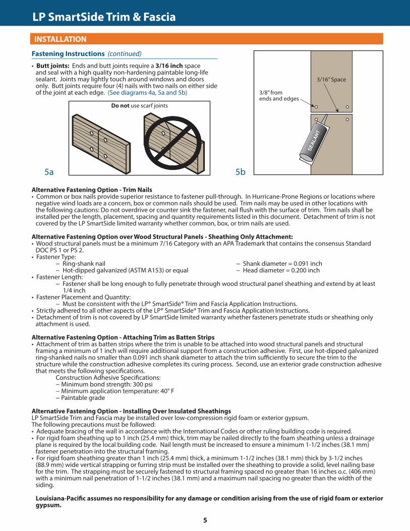
• Butt joints: Ends and butt joints require a 3/16 inch space and seal with a high quality non-hardening paintable long-life sealant. Joints may lightly touch around windows and doors only. Butt joints require four (4) nails with two nails on either side of the joint at each edge. (See diagrams 4a, 5a and 5b)
GENERAL REQUIREMENTS (CONTINUED)
Alternative Fastening Option - Trim Nails• Common or box nails provide superior resistance to fastener pull-through. In Hurricane-Prone Regions or locations where
negative wind loads are a concern, box or common nails should be used. Trim nails may be used in other locations with the following cautions: Do not overdrive or counter sink the fastener, nail flush with the surface of trim. Trim nails shall be installed per the length, placement, spacing and quantity requirements listed in this document. Detachment of trim is not covered by the LP SmartSide limited warranty whether common, box, or trim nails are used.
Alternative Fastening Option over Wood Structural Panels - Sheathing Only Attachment: • Wood structural panels must be a minimum 7/16 Category with an APA Trademark that contains the consensus Standard
DOC PS 1 or PS 2. • Fastener Type: − Ring-shank nail − Shank diameter = 0.091 inch − Hot-dipped galvanized (ASTM A153) or equal − Head diameter = 0.200 inch• Fastener Length: − Fastener shall be long enough to fully penetrate through wood structural panel sheathing and extend by at least 1/4 inch• Fastener Placement and Quantity: − Must be consistent with the LP® SmartSide® Trim and Fascia Application Instructions. • Strictly adhered to all other aspects of the LP® SmartSide® Trim and Fascia Application Instructions. • Detachment of trim is not covered by LP SmartSide limited warranty whether fasteners penetrate studs or sheathing only
attachment is used.
Alternative Fastening Option - Attaching Trim as Batten Strips• Attachment of trim as batten strips where the trim is unable to be attached into wood structural panels and structural
framing a minimum of 1 inch will require additional support from a construction adhesive. First, use hot-dipped galvanized ring-shanked nails no smaller than 0.091 inch shank diameter to attach the trim sufficiently to secure the trim to the structure while the construction adhesive completes its curing process. Second, use an exterior grade construction adhesive that meets the following specifications.
Construction Adhesive Specifications: − Minimum bond strength: 300 psi − Minimum application temperature: 40° F − Paintable grade
Alternative Fastening Option - Installing Over Insulated SheathingsLP SmartSide Trim and Fascia may be installed over low-compression rigid foam or exterior gypsum. The following precautions must be followed: • Adequate bracing of the wall in accordance with the International Codes or other ruling building code is required. • For rigid foam sheathing up to 1 inch (25.4 mm) thick, trim may be nailed directly to the foam sheathing unless a drainage
plane is required by the local building code. Nail length must be increased to ensure a minimum 1-1/2 inches (38.1 mm) fastener penetration into the structural framing.
• For rigid foam sheathing greater than 1 inch (25.4 mm) thick, a minimum 1-1/2 inches (38.1 mm) thick by 3-1/2 inches (88.9 mm) wide vertical strapping or furring strip must be installed over the sheathing to provide a solid, level nailing base for the trim. The strapping must be securely fastened to structural framing spaced no greater than 16 inches o.c. (406 mm) with a minimum nail penetration of 1-1/2 inches (38.1 mm) and a maximum nail spacing no greater than the width of the siding.
Louisiana-Pacific assumes no responsibility for any damage or condition arising from the use of rigid foam or exterior gypsum.
5b5a
Fastening Instructions (continued)
3/8” from ends and edges
3/16” Space
Do not use scarf joints
LP SmartSide Trim & Fascia
5
TRIM & FASCIA 190, 440, 540 & 2000 SERIESINSTALLATION
• Trim must extend beyond the face of the siding. Trim may be installed directly to the sheathing, or directly over the siding.
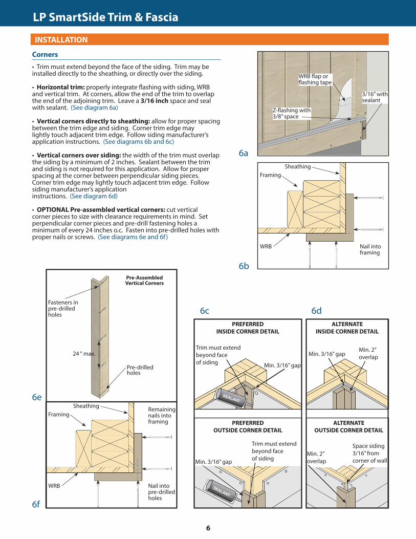
• Horizontal trim: properly integrate flashing with siding, WRB and vertical trim. At corners, allow the end of the trim to overlap the end of the adjoining trim. Leave a 3/16 inch space and seal with sealant. (See diagram 6a)
• Vertical corners directly to sheathing: allow for proper spacing between the trim edge and siding. Corner trim edge may lightly touch adjacent trim edge. Follow siding manufacturer’s application instructions. (See diagrams 6b and 6c)
• Vertical corners over siding: the width of the trim must overlap the siding by a minimum of 2 inches. Sealant between the trim and siding is not required for this application. Allow for proper spacing at the corner between perpendicular siding pieces. Corner trim edge may lightly touch adjacent trim edge. Follow siding manufacturer’s application instructions. (See diagram 6d)
• OPTIONAL Pre-assembled vertical corners: cut vertical corner pieces to size with clearance requirements in mind. Set perpendicular corner pieces and pre-drill fastening holes a minimum of every 24 inches o.c. Fasten into pre-drilled holes with proper nails or screws. (See diagrams 6e and 6f )
GENERAL REQUIREMENTS (CONTINUED)
6a
6b
6f
3/16” with sealant
Nail into framing
Min. 3/16” gap
Trim must extend beyond face of siding
PREFERREDINSIDE CORNER DETAIL
Corners
WRB flap or flashing tape
Z-flashing with 3/8” space
SheathingFraming
WRB
Nail into pre-drilled holes
SheathingFraming
WRB
Remaining nails into framing
Pre-Assembled Vertical Corners
Fasteners in pre-drilled holes
24 “ max.
Pre-drilled holes
6e
Min. 3/16” gapMin. 2” overlap
ALTERNATEINSIDE CORNER DETAIL
Min. 3/16” gap
Trim must extend beyond face of siding
PREFERREDOUTSIDE CORNER DETAIL
Space siding 3/16” from corner of wall
Min. 2” overlap
ALTERNATEOUTSIDE CORNER DETAIL
6c 6d
LP SmartSide Trim & Fascia
6
TRIM & FASCIA 190, 440, 540 & 2000 SERIESINSTALLATION
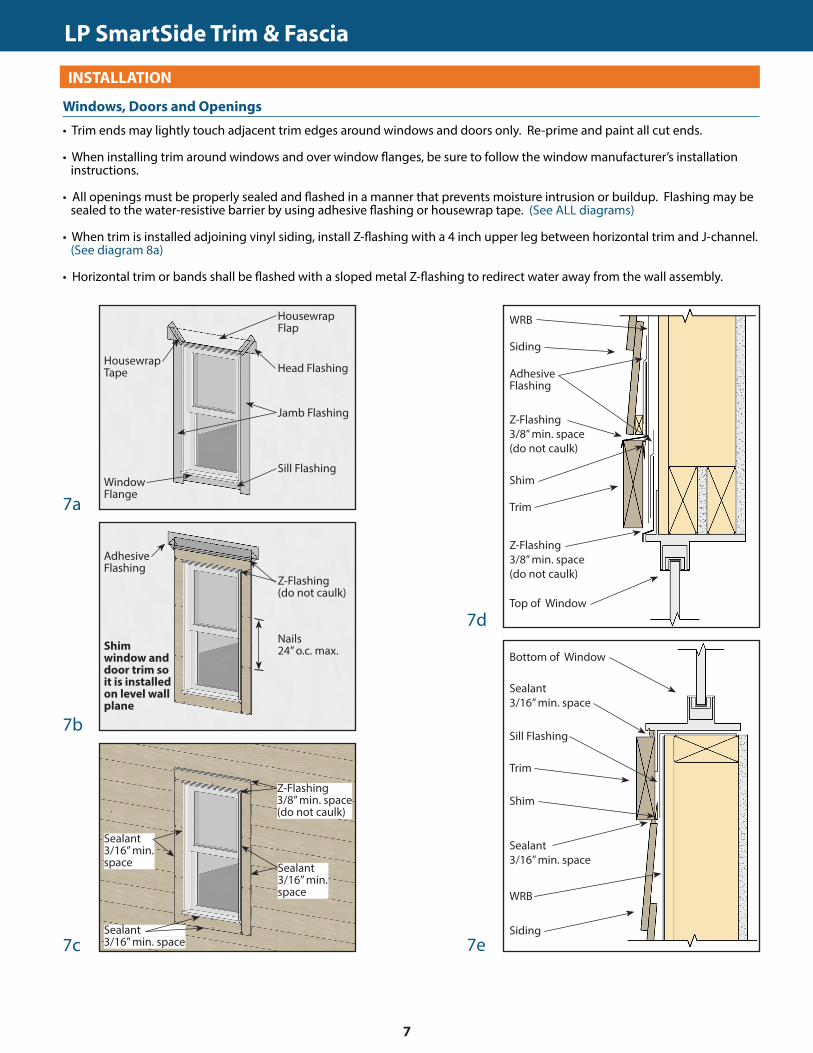
• Trim ends may lightly touch adjacent trim edges around windows and doors only. Re-prime and paint all cut ends.
• When installing trim around windows and over window flanges, be sure to follow the window manufacturer’s installation instructions.
• All openings must be properly sealed and flashed in a manner that prevents moisture intrusion or buildup. Flashing may be sealed to the water-resistive barrier by using adhesive flashing or housewrap tape. (See ALL diagrams)
• When trim is installed adjoining vinyl siding, install Z-flashing with a 4 inch upper leg between horizontal trim and J-channel. (See diagram 8a)
• Horizontal trim or bands shall be flashed with a sloped metal Z-flashing to redirect water away from the wall assembly.
GENERAL REQUIREMENTS (CONTINUED)
7a
7b
Nails 24” o.c. max.
Windows, Doors and Openings
Z-Flashing (do not caulk)
Adhesive Flashing
Shim window and door trim so it is installed on level wall plane
7c
Housewrap Tape
Window Flange
Housewrap Flap
Head Flashing
Jamb Flashing
Sill Flashing
Sealant 3/16” min. space
Sealant 3/16” min. space
Sealant 3/16” min. space
Z-Flashing 3/8” min. space (do not caulk)
WRB
Siding
Z-Flashing 3/8” min. space (do not caulk)
Shim
Adhesive Flashing
Top of Window
Trim
Z-Flashing 3/8” min. space (do not caulk)
WRB
Siding
Shim
Sill Flashing
Bottom of Window
Trim
Sealant 3/16” min. space
Sealant 3/16” min. space
7d
7e
LP SmartSide Trim & Fascia
7
TRIM & FASCIA 190, 440, 540 & 2000 SERIESINSTALLATION
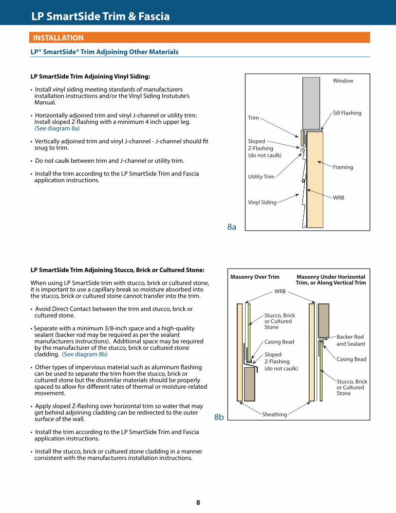
LP SmartSide Trim Adjoining Vinyl Siding:
• Install vinyl siding meeting standards of manufacturers installation instructions and/or the Vinyl Siding Instutute’s Manual.
• Horizontally adjoined trim and vinyl J-channel or utility trim: Install sloped Z-flashing with a minimum 4 inch upper leg.
(See diagram 8a)
• Vertically adjoined trim and vinyl J-channel - J-channel should fit snug to trim.
• Do not caulk between trim and J-channel or utility trim.
• Install the trim according to the LP SmartSide Trim and Fascia application instructions.
GENERAL REQUIREMENTS (CONTINUED)LP® SmartSide® Trim Adjoining Other Materials
Window
Sill Flashing
SlopedZ-Flashing(do not caulk)
Utility Trim
Trim
Framing
Vinyl SidingWRB
Sheathing
Sloped Z-Flashing (do not caulk)
Stucco, Brick or Cultured Stone
Masonry Over Trim
Casing Bead
WRB
Backer Rod and Sealant
8a
8b
LP SmartSide Trim Adjoining Stucco, Brick or Cultured Stone:
When using LP SmartSide trim with stucco, brick or cultured stone, it is important to use a capillary break so moisture absorbed into the stucco, brick or cultured stone cannot transfer into the trim. • Avoid Direct Contact between the trim and stucco, brick or
cultured stone.
• Separate with a minimum 3/8-inch space and a high-quality sealant (backer rod may be required as per the sealant manufacturers instructions). Additional space may be required by the manufacturer of the stucco, brick or cultured stone cladding. (See diagram 8b)
• Other types of impervious material such as aluminum flashing can be used to separate the trim from the stucco, brick or cultured stone but the dissimilar materials should be properly spaced to allow for different rates of thermal or moisture-related movement.
• Apply sloped Z-flashing over horizontal trim so water that may get behind adjoining cladding can be redirected to the outer surface of the wall.
• Install the trim according to the LP SmartSide Trim and Fascia application instructions.
• Install the stucco, brick or cultured stone cladding in a manner consistent with the manufacturers installation instructions.
Masonry Under Horizontal Trim, or Along Vertical Trim
Casing Bead
Stucco, Brick or Cultured Stone
LP SmartSide Trim & Fascia
8
TRIM & FASCIA 190, 440, 540 & 2000 SERIESINSTALLATION
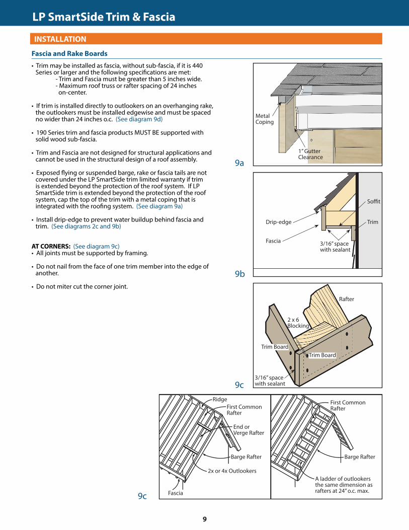
• Trim may be installed as fascia, without sub-fascia, if it is 440 Series or larger and the following specifications are met:
- Trim and Fascia must be greater than 5 inches wide. - Maximum roof truss or rafter spacing of 24 inches on-center.
• If trim is installed directly to outlookers on an overhanging rake, the outlookers must be installed edgewise and must be spaced no wider than 24 inches o.c. (See diagram 9d)
• 190 Series trim and fascia products MUST BE supported with solid wood sub-fascia.
• Trim and Fascia are not designed for structural applications and cannot be used in the structural design of a roof assembly.
• Exposed flying or suspended barge, rake or fascia tails are not covered under the LP SmartSide trim limited warranty if trim is extended beyond the protection of the roof system. If LP SmartSide trim is extended beyond the protection of the roof system, cap the top of the trim with a metal coping that is integrated with the roofing system. (See diagram 9a)
• Install drip-edge to prevent water buildup behind fascia and trim. (See diagrams 2c and 9b)
AT CORNERS: (See diagram 9c)• All joints must be supported by framing.
• Do not nail from the face of one trim member into the edge of another.
• Do not miter cut the corner joint.
GENERAL REQUIREMENTS (CONTINUED)
9a
9b
3/16” space with sealant
Fascia and Rake Boards
Soffit
Drip-edge
9c
Metal Coping
1” Gutter Clearance
9c
Fascia
Trim
Trim BoardTrim Board
2 x 6 Blocking
Rafter
3/16” space with sealant
Barge Rafter
RidgeFirst Common Rafter
End or Verge Rafter
2x or 4x Outlookers
Fascia
A ladder of outlookers the same dimension as rafters at 24” o.c. max.
First Common Rafter
Barge Rafter
LP SmartSide Trim & Fascia
9
TRIM & FASCIA 190, 440, 540 & 2000 SERIESINSTALLATION
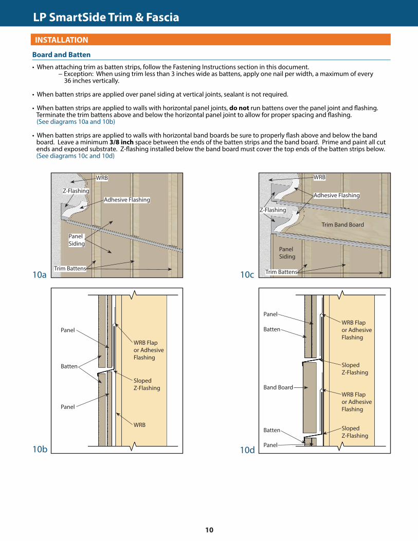
• When attaching trim as batten strips, follow the Fastening Instructions section in this document. − Exception: When using trim less than 3 inches wide as battens, apply one nail per width, a maximum of every 36 inches vertically.
• When batten strips are applied over panel siding at vertical joints, sealant is not required.
• When batten strips are applied to walls with horizontal panel joints, do not run battens over the panel joint and flashing. Terminate the trim battens above and below the horizontal panel joint to allow for proper spacing and flashing.
(See diagrams 10a and 10b)
• When batten strips are applied to walls with horizontal band boards be sure to properly flash above and below the band board. Leave a minimum 3/8 inch space between the ends of the batten strips and the band board. Prime and paint all cut ends and exposed substrate. Z-flashing installed below the band board must cover the top ends of the batten strips below. (See diagrams 10c and 10d)
GENERAL REQUIREMENTS (CONTINUED)
10a 10c
Board and Batten
Z-Flashing
WRB
Adhesive Flashing
Panel Siding
Trim Battens
WRB
Panel
WRB Flap or Adhesive Flashing
Batten
Panel
Sloped Z-Flashing
10b 10d
Z-Flashing
WRB
Adhesive Flashing
Panel Siding
Trim Battens
Trim Band Board
PanelWRB Flap or Adhesive Flashing
Batten
Panel
Sloped Z-Flashing
WRB Flap or Adhesive Flashing
Sloped Z-Flashing
Batten
Band Board
LP SmartSide Trim & Fascia
10
TRIM & FASCIA 190, 440, 540 & 2000 SERIESINSTALLATION
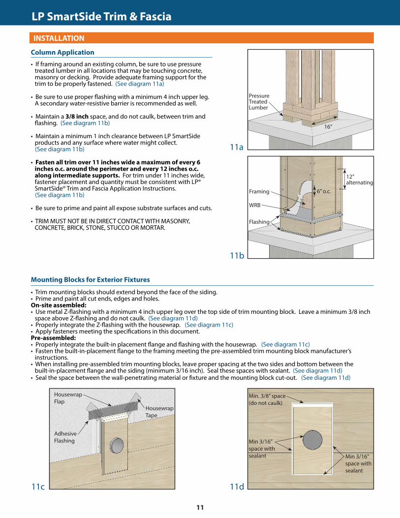
• If framing around an existing column, be sure to use pressure treated lumber in all locations that may be touching concrete, masonry or decking. Provide adequate framing support for the trim to be properly fastened. (See diagram 11a)
• Be sure to use proper flashing with a minimum 4 inch upper leg. A secondary water-resistive barrier is recommended as well.
• Maintain a 3/8 inch space, and do not caulk, between trim and flashing. (See diagram 11b)
• Maintain a minimum 1 inch clearance between LP SmartSide products and any surface where water might collect.
(See diagram 11b)
• Fasten all trim over 11 inches wide a maximum of every 6 inches o.c. around the perimeter and every 12 inches o.c. along intermediate supports. For trim under 11 inches wide, fastener placement and quantity must be consistent with LP® SmartSide® Trim and Fascia Application Instructions.
(See diagram 11b)
• Be sure to prime and paint all expose substrate surfaces and cuts.
• TRIM MUST NOT BE IN DIRECT CONTACT WITH MASONRY, CONCRETE, BRICK, STONE, STUCCO OR MORTAR.
GENERAL REQUIREMENTS (CONTINUED)
• Trim mounting blocks should extend beyond the face of the siding.• Prime and paint all cut ends, edges and holes.On-site assembled:• Use metal Z-flashing with a minimum 4 inch upper leg over the top side of trim mounting block. Leave a minimum 3/8 inch
space above Z-flashing and do not caulk. (See diagram 11d)• Properly integrate the Z-flashing with the housewrap. (See diagram 11c)• Apply fasteners meeting the specifications in this document.Pre-assembled:• Properly integrate the built-in placement flange and flashing with the housewrap. (See diagram 11c)• Fasten the built-in-placement flange to the framing meeting the pre-assembled trim mounting block manufacturer’s
instructions. • When installing pre-assembled trim mounting blocks, leave proper spacing at the two sides and bottom between the
built-in-placement flange and the siding (minimum 3/16 inch). Seal these spaces with sealant. (See diagram 11d)• Seal the space between the wall-penetrating material or fixture and the mounting block cut-out. (See diagram 11d)
11a
CUTTING
11b
11c 11d
16”
6” o.c.
Housewrap Flap
Adhesive Flashing
Column Application
Mounting Blocks for Exterior Fixtures
Pressure Treated Lumber
WRB
Framing
Flashing
12” alternating
Min. 3/8” space (do not caulk)
Min 3/16” space with sealant
Housewrap Tape
Min 3/16” space with sealant
LP SmartSide Trim & Fascia
11

TRIM & FASCIA 190, 440, 540 & 2000 SERIESINSTALLATION
DO• Prime and paint all exposed surfaces including all drip edges or where water will hang.• Apply finish coat as soon as possible or within 180 days of application.• Use paints and sealants that meet specifications in the General Application Equipment section in this document.• Follow the coating manufacturer’s application and maintenance instructions.
DO NOT USE• Semi-transparent and transparent stains.• Shake and shingle paints.• Vinyl-based resin formulas such as vinyl acetate, PVA, vinyl acetate/acrylic copolymer paints.
CAUTION:HANDLE PREFINISHED LP PRODUCTS WITH EXTREME CARE DURING STORAGE AND APPLICATION.
TOUCH UP ANY DAMAGE TO THE FINISH THAT MAY OCCUR DURING APPLICATION PER PREFINISHERS SPECIFICATIONS.
GENERAL REQUIREMENTS (CONTINUED)Finishing Instructions
Cal. Prop 65 Warning: Use of this product may result in exposure to wood dust, known to the State of California to cause cancer.
Louisiana-Pacific Corporation 414 Union St. Nashville, TN 37219
www.lpcorp.com www.lpsmartside.com
© 2016 Louisiana-Pacific Corporation. All rights reserved. LP and SmartSide are registered trademarks of Louisiana-Pacific Corporation. Printed in U.S.A.
NOTICE: Louisiana-Pacific Corporation periodically updates and revises its product information. The information in this document is subject to change without notice. To verify that this version is current, call 800-450-6106.
LPZB0521 02/16
LP SmartSide Trim & Fascia
LIMITED WARRANTYThe Louisiana-Pacific Corporation (“LP”) LP® SmartSide® trim and fascia (the “Products”) limited warranty (the “Warranty”) applies only to structures on which the Products have been applied, finished and maintained in accordance with the published application, finishing and maintenance instructions in effect at the time of application. Products affected by a failure to follow such application, finishing or maintenance instructions (“Affected Products”) will be excluded from coverage under the Warranty.LP assumes no liability for any loss or damage caused by the Affected Products and is expressly released by the purchaser or owner from any such loss or liability.Any modification of the Warranty or the application, finishing and maintenance requirements is void unless approved in writing by LP prior to application.
For a copy of the warranty or installation and technical support, visit the LP Web site at: www.lpcorp.comWARRANTY REMEDIES ARE NOT AVAILABLE IF REQUIREMENTS ARE NOT FOLLOWED. or for additional support call 800-450-6106
12