Embed Size (px)
Citation preview

1
LP-PAN
Software Defined IQ Panadapter
Assembly Manual
September 2011 TelePost Incorporated
Rev. F9

2
Table of Contents
Introduction ......................................................................................................... 3
Parts List .............................................................................................................. 4 Assembly ............................................................................................................. 7 Circuit Description ............................................................................................. 12 Schematic ......................................................................................................... 13 Specifications and Warranty ............................................................................. 14
Copyright and Trademark Disclosures LP-PAN is a trademark of TelePost Inc. Windows® is a registered trademark of Microsoft Corporation. Material in this document copyrighted ©2007-10 TelePost Inc. All rights reserved. LP-Bridge copyrighted ©2007-10 TelePost Inc. All rights reserved. PowerSDRTM is an open source application for use with IQ based software defined radios, and is a trademark of FlexRadio Systems.

3
Introduction Read Carefully Before Continuing. Assembling LP-PAN is a straightforward job, and you should have no trouble if you follow the instructions. Take special note of the connection diagram, and become familiar with the basics of how the various components fit together in the system. Installing and configuring PowerSDR can be tricky. It is a complex program, and requires quite a few steps to get set up properly. Lots of Flex Radio users have done this though, so don’t let it scare you. Pay special attention to the sound card setup. If you’re using the E-MU 0202 USB sound card, you will probably want to visit the Creative Labs website for the latest driver. The E-MU driver does not support Windows 2000, but works with XP and VISTA, 32 and 64. There is some question about whether there may be a problem in XP SP3 though. I believe SP3 post dates the latest E-MU driver, though. If you get in trouble, help is an email away. There are plenty of helpful users on the LP-PAN User Group, http://groups.yahoo.com/group/LP-PAN/ , or you can send an email to [email protected]. Phone support is also available at 734-455-3716.
LP-PAN Features LP-PAN is a software defined IQ direct conversion panadapter. Here is a list of current features... * Up to 192 kHz display on PC, sound card dependent * Switching quadrature detector for high dynamic range * Strong buffer amp with low NF and very high LO isolation. * Excellent THD and IMD performance * Ground isolated inputs / outputs with mil spec audio xfmrs * Low output Z, balanced or unbalanced. * Fully balanced architecture with balanced and unbalanced outputs * Jumperable ground lift on RF input and audio outputs * Works with many SDR programs. * Adjustable gain to interface almost any sound card * Point and click frequency control with PowerSDR / IF Stage and LP-Bridge or HRD . In addition, LP-Bridge allows sharing of K3 / LP- PAN with almost any logger, and even programs such as CW-Skimmer * Powder coated aluminum enclosure with silk screened graphics. * Hardware or software mute * Available for IF frequencies of… 8.215 MHz (Elecraft K3) 8.83 MHz (Kenwood) 9.0 MHz (Orion) 4.915 MHz (Elecraft K2) 10.7 MHz (IC-R8500/9500, others) 10.55 MHz (FT-2000) Note: Specifications dependent on sound card, and subject to change. Cited values were taken with an E-MU 0202 USB sound card. All measurements also apply to E-MU 1212m and 1616m PCI cards, and M-Audio Firewire Audiophile 2496 card (limited only by 96 kHz display width). For latest sound card info, see www.telepostinc.com/soundcards.html

4
Parts List - Subject to change without notice. Pictures shown at end of parts list.
Pre-installed SMT parts
Quantity Designation Description
5 C5,11,18, 31, 39 0.01uF
2 C4, 6 0.1uF
1 C7 1uF
1 C9 0.22uF
1 L4 10uH
1 L8 12uH
0 L9,10 0.11uH (alternate to L11,12)
2 L11, 12 0.11uH
2 R1, 3 1K 1%
1 R4 4.7K 1%
1 R5 200 ohm 1%
2 R6, 7 499 ohm 1%
2 R8, 28 49.9 ohm 1%
1 T3 Toroid XFMR 1:1
1 T4 Toroid XFMR 4:1
1 U11 ADCMP600 Comparator
1 U2 74HC/HCT163 Counter
2 U4,7 LT6231 Low Noise Op-Amp
1 U5 AD8007 Transconductance Amplifier
1 U8 SN74CBT3253D 4x2 Analog Multiplexer
Through-Hole Parts
Quantity Designation Value
1 C1 10pF ceramic disc (marked 10) Fig. 3
6 C2,3,8,20,33,42 0.1uF monolithic (marked 104) Fig. 1
1 C10 See Table I, Page 6 Figs. 3, 4
1 C12 See Table I, Page 6 Figs. 3, 4
1 C13 See Table I, Page 6 Figs. 3, 4
8 C14,16,22,24,27,29,32,37
0.01uF ceramic disc (marked 103) Fig. 3
5 C15,17,23,25,38 1uF (25V electrolytic) Fig. 2
1 C19 100uF (25V electrolytic) Fig. 28
2 C21,28 See Table I, Page 6 Figs. 3, 4 1 C26 10uF (25V electrolytic) Fig. 2
1 C30 See Table I, Page 6 Figs. 3, 4
2 C34,35 4-20pF trimmer cap Fig. 19
1 C36 56pF ceramic disc (marked 56) Fig. 3
1 C40 0.001uF ceramic disc (102) Fig. 3
2 C41,43 See Table I, Page 6 Figs. 3, 4
1 D1 Green LED Fig. 9
1 D2 1N4148 Fig. 18
1 J1 Insulated BNC connector Fig. 17
2 J2,13 3.5mm Stereo Audio Jack Fig. 20
1 J3 RCA Jack Fig. 21
1 J11 2.5mm DC Power Connector Fig. 7
4 2-pin Jumper Fig. 11
3 JP1-3 2-pin Header Fig. 11

5
Quantity Designation Value
1 JP4 3-pin Header Fig. 11
6 L1,2,3,5,6,7 1mH RF Choke (br-bk-rd) Fig. 5
1 Q1 MPS5179 transistor Fig. 10
2 R2,31 10 ohm 1/8W res. (br-bk-bk) Fig. 12
4 R9,17,18,34 1K 5% 1/8W res. (br-bk-rd) Fig. 12
4 R10,14,15,16 1.1K 1% 1/8W res. (br-br-bk-br-br) Fig. 12
1 R11 1.5K 5% res. (br-grn-rd) Fig. 12
3 R12,21,22 2K 5% 1/8W res. (rd-bk-rd) Fig. 12
4 R13,19,20,27 22 ohm 1% 1/8W res. (rd-rd-bk-gld-br) Fig. 12
1 R23 1K Pot Fig. 22
1 R24 4.7K 5% 1/8W res. (yel-viol-rd) Fig. 12
1 R25 27K 5% 1/8W res. (rd-viol-or) Fig. 12 (1% alt.)
1 R26 470 ohm 5% 1/8W res. (yel-viol-br) Fig. 12
1 R29 200 ohm Pot Fig. 23
1 R35 10K 5% 1/8W res. (br-bk-or) Fig. 12
1 SW11 4PDT Pushbutton Switch & Keycap Fig. 6
2 T1,2 Audio Output Xfmr, 600 ohm Fig. 25
1 U1 78L05 5V Regulator Fig. 10
1 Y1 See Table I, Page 6 Figs. 24
1 PCB Fig. 26
1 Enclosure Fig. 27
1 Power Cord Fig. 8
6 ¼” Black Sheet metal screw Fig. 14
8 3/16" Black machine screw Fig. 15
4 1/4" standoff Fig. 13
4 Rubber feet Fig. 16
Fig. 1
Fig. 2
Fig. 3
Fig. 4
Fig. 5
Fig. 7
Fig. 8
Fig. 9
Fig. 10
Fig. 11
Fig. 12
Fig. 13
Fig. 14
Fig. 15
Fig. 6
Parts List – Cont’d

6
Radio Nominal IF (MHz)
Y1 (MHz) C10 C12 C13 C21/28 C30 C41/43
Elecraft K2 4.915 19.68000 47pF(47) 82pF(82) 68pF(68) 4700pF(472) 47pF(47) 4700pF(472)
Elecraft K3 8.215 32.83600 10pF(10) 18pF(18) 10pF(10) 2700pF(272) 100pF(101) 560pF(561)
Kenwood (w/SM-220 IF Output)
8.830 35.29600 10pF(10) 10pF(10) 10pF(10) 2700pF(272) 100pF(101) 220pF(221)
TenTec Orion (II)
9.000 35.976 10pF(10) 10pF(10) 10pF(10) 2700pF(272) 100pF(101) None
Yaesu FTdx5000
9.000 35.976 10pF(10) 10pF(10) 10pF(10) 2700pF(272) 100pF(101) None
Yaesu FT-2000
10.550 42.224 10pF(10) None None 1000pF(102) 100pF(101) 1000pF(102)
Kenwood TS-2000
10.695 14.27643 10pF(10) None None 1000pF(102) 100pF(101) 1000pF(102)
IC-R7000 / 8500 / 9500 AOR
10.700 14.27643 10pF(10) None None 1000pF(102) 100pF(101) 1000pF(102)
Table I
Note: Some brands of cap with values below 100pF are marked with a trailing “0” and some aren’t. At least one 10.7 MHz receiver puts a DC voltage on its IF output jack for control of proprietary accessories. Before connecting your radio to LP-PAN, make sure that its IF output does not have a DC voltage on it. If it does, you will need to add a 0.01uF blocking cap between the LP-PAN BNC connector and the input transformer. Assembled LP-PANs for 10.7 Mhz have been modified thusly.
Fig. 17
Fig. 19
Fig. 20
Fig. 21
Parts List – Cont’d
Fig. 22
Fig. 23
Fig. 24
Fig. 25
Fig. 26
Fig. 27
Fig. 28
Fig. 18
Fig. 16

7
Assembly
Important warnings – read this before starting assembly You should visually inspect all the solder pads/traces with a magnifier for any etching problems. This is done before shipping, but I recommend the builder do a second inspection as well. We do 100% continuity checks of all pads before shipment using computer controlled flying probes based on PCB netlist coordinates.
All of the SMT components are pre-installed on the main board for your convenience. SMT parts are supplied wherever necessary for performance or availability reasons. CAUTION: Be very careful handling this board to avoid damage to the installed parts. Anti-static measures are highly recommended, such as use of an anti-static mat, grounded soldering iron and wrist band. You may wish to clean the flux from the board after assembly, although it is not necessary with most modern solders. A toothbrush and alcohol are good for this. Only use rosin core solder. Use of acid core solder voids the warranty. Lead-free solder is OK, and the boards are RoHS compliant, but it will be more difficult to remove parts without damaging the board should you have to.
Overview Below is the component placement diagram for the main PCB. These markings match the silk-screening on the PCB, but are repeated here for clarity. You can also cross out the parts on this graphic as they are installed. You should check all parts before starting to allow you to start the process of obtaining replacement parts as soon as possible if needed. It is also a good idea to sort the parts in advance… egg cartons are handy for this (passive parts only). Many crafts stores, Like Michael’s, also have nice plastic cases with dividers at low prices. If there is any doubt about component values, especially with the 1% resistors which can use strange markings, check them with your DMM.

8
Assembly Cont’d
Pre-assembly overview.
When assembly starts on page 9, it will roughly follow this order… Installation of resistors Installation of ceramic disc capacitors Installation of miscellaneous small parts Installation of miscellaneous large parts and connectors Installation of chokes The idea is be able to lay the board flat as much as possible during construction, with lowest parts being installed first. The chokes are the lone exemption… they are installed last so as to make sure each circuit is drawing the right amount of current before continuing. This is done by monitoring total current draw of LP-PAN while adding the chokes one by one. You will need the following tools to complete assembly…
Adjustable soldering iron – 800 degrees maximum 60/40 alloy solder… .020” (0.51mm) diameter recommended for thermal pads Needle-nose pliers Wire cutters Small Philips head screwdriver Digital Multimeter NOTE: The LP-PAN is an intermediate level kit. I would peg the assembly time at about 2-3 hours, plus some reading through the manual in advance, and some time for calibration afterward. Take your time, and double-check your work, and you should have no problem. All critical parts are pre-installed.

9
Assembly Cont’d Step-by-step assembly instructions.
Below is a picture of the assembled PCB. The SMT parts come pre-installed. The component layout diagram on page 7 provides another aid to component identification. Units after #309 will be ever so slighlty different… mainly in the area of C41 & C43.
It is recommended that you print at least this portion of the manual to allow for easy reference while building, and to allow you to check off the steps as you complete them. Make sure your work area is static-free to avoid damage to the pre-installed SMT parts. It is also advisable to wear an anti-static wrist band and grounded soldering iron. Refer to the parts placement graphic on page 7 or the above picture for questions regarding parts placement. Install resistors. Solder and clip leads after about six parts are installed to minimize clutter. If you are unsure of the colors used by
some of the manufacturers for the color code, especially the 1% parts, measure the value with a DMM. Occasionally, parts listed as 5% will be supplied as 1% due to availability when ordering. Double check with DMM.
R2,31 10 ohm 1/8W res. (br-blk-bk) R9,17,18,34 1K 5% 1/8W res. (br-blk-rd) R10,14,15,16 1.1K 1% 1/8W res. (br-br-blk-br-br) R11 1.5K 5% res. (br-grn-rd) R12 2K 5% 1/8W res. (rd-rd-blk-br-br) or 2.2K 1% (rd-r-bk-br-br) R13,19,20,27 22 ohm 1% 1/8W res. (rd-rd-bk-gld-br) R21,22 2K 5% 1/8W res. (rd-bk-rd) R24 4.7K 5% 1/8W res. (yel-viol-rd) R35 10K 5% 1/8W res. (br-bk-or) R25 27K 5% 1/8W res. (rd-viol-or) R26 470 ohm 5% 1/8W res. (yel-viol-br) Install the two audio jacks next. Solder the center lead first, so that you can adjust the jacks to be parallel with the board edge
before soldering the remaining pins. Install D2. Follow polarity markings on PCB.

10
Assembly Cont’d
Install all 0.1 uF caps (marked 104). C2 C3 C8 C20 C33 C42 Install all .01 uF caps (marked 103). C14 C16 C22 C24 C27 C29 C32 C37 Install remaining ceramic disc and SM caps, and the two trimmer caps. C1 10pF ceramic disc (marked 10) C10 See Table I, page 6 C12 See Table I, page 6 C13 See Table I, page 6 C30 See Table I, page 6 C36 56pF ceramic disc (marked 56) C40 0.001uF ceramic disc (102) C34. 35 4-20pF trimmer cap C21, 28 See Table I, page 6 C41, 43 See Table I, page 6
Install D1 (LED) Install Q1. Keep leads short. Install U1. Keep leads short. Install R29 (pot). Install SW11 Install J3. You will need to clip off the two plastic tabs on the bottom of the connector off before installing. Latch the rear pin first for
strength, then solder the front pin. Install J11 Install the three 2-pin and one 3-pin headers. Install a shorting jumper between pins
at JP2. Install a jumper on the ground pin only on JP1 & JP3. Install a jumper between pins 2 & 3 of JP4 (the two toward the front of the board).
Install T1 and T2. Orient pin 1 near the silk-screened “1” marking, as shown. Install R23 (pot) Install crystal, Y1. See Table I, page 6 for value. Install the electrolytics, taking care with polarity. The “+” lead is the longer one, “-“
lead is marked with a black or white stripe, or blue semi-circle.
C15, 17, 23, 25, 38 1uF (25V) C19 100uF (25V) C26 10uF (25V)
11
Assembly Cont’d Install J1
Make sure that your bench is clean and the PCB is not sitting on any cut off component leads. Connect supplied power cable to a supply of 11-16 VDC. The dashed white lead on the supplied power cable is the + lead (center pin). The green LED should light. Using your DMM, check for 5.0 VDC (+/- 0.25V) at pin 3 of U1 (the pin connected to C3). Monitor total current draw of LP-PAN using the DMM or current meter on a power supply. Current draw should be 28mA. Power down.
Install the 1mH ceramic chokes (br-blk-red) one at a time, and check LP-PAN current draw as each one is added to verify no
unexpectedly high changes to total current draw. Expected total current draw is shown after each choke. If your values vary significantly from these, check your work in the circuit affected by the most recently added choke. Refer to schematic.
L5 29mA L7 31mA L1 39mA L2 41mA L3 47mA L6 53mA Attach the four rubber feet to the bottom of the enclosure. Install the PCB in enclosure using 3/16” black screws and ¼” standoffs. Loosely install the standoffs on the bottom, and then slide
the board into place, rear first. Attach the screws from the top while aligning the holes on the rear panel, then tighten the screws underneath.
Install keycap on SW11. The enclosure top will be installed after calibration.
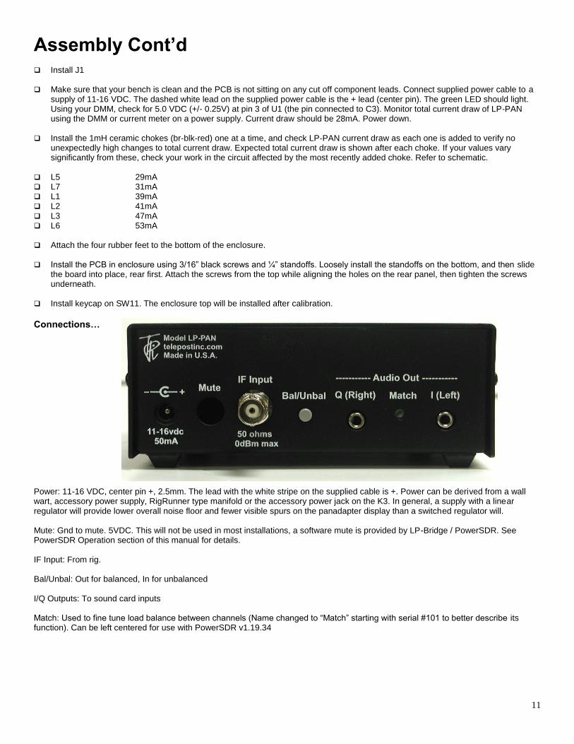
Connections… Power: 11-16 VDC, center pin +, 2.5mm. The lead with the white stripe on the supplied cable is +. Power can be derived from a wall wart, accessory power supply, RigRunner type manifold or the accessory power jack on the K3. In general, a supply with a linear regulator will provide lower overall noise floor and fewer visible spurs on the panadapter display than a switched regulator will. Mute: Gnd to mute. 5VDC. This will not be used in most installations, a software mute is provided by LP-Bridge / PowerSDR. See PowerSDR Operation section of this manual for details. IF Input: From rig. Bal/Unbal: Out for balanced, In for unbalanced I/Q Outputs: To sound card inputs Match: Used to fine tune load balance between channels (Name changed to “Match” starting with serial #101 to better describe its function). Can be left centered for use with PowerSDR v1.19.34

12
Circuit Description
LP-PAN is a direct conversion quadrature receiver with baseband audio In-Phase (I) and Quadrature (Q) outputs. These outputs are fed to a high quality sound card for DSP processing in applications such as PowerSDR. The input is taken from the IF output connector of a receiver. Values shown are for Elecraft K3. The signal has a very wide bandwidth, and is bandpass filtered down to about 400 kHz in the front end of LP-PAN. This helps with out of band signals that are strong enough to get by the K3’s input filters, and also blocks mixer products that are present in the K3’s IF output. The filtered signal is then sent to a high isolation buffer amplifier. This amp serves a couple purposes. One is to add gain lost in the K3 IF output stage, which is quite lossy. The second is to isolate the K3 from the strong L.O. signal present at the input of the quadrature mixer. The buffer amp has over 80 dB of isolation, and is capable of reducing the L.O. leakage to a level well below the K3’s noise floor in combination with the K3 internal buffer. The buffer has a very low noise figure, and high IP3 (>+40dBm) so as to not degrade the excellent IMD performance of the K3. The quadrature mixer is operated in a doubly balanced configuration and provides balanced outputs to the preamps. Very low noise preamps with rail-to-rail outputs were chosen to maximize dynamic range. The preamps are direct coupled to a pair of very broadband transformers to preserve the balanced nature of the design, and minimize 2
nd harmonic distortion. The outputs of the transformers can
drive either balanced or unbalanced loads. The output Z was chosen to be low (600 ohms) to allow driving almost any sound card. I include internal 2K loads to set a maximum load Z when used with very high impedance sound cards, and present closer to 600 ohms with more typical sound card loads. The load values were chosen experimentally for maximum gain and phase flatness, and one is adjustable to facilitate matching the channels exactly. This is critical in achieving 60dB broadband image rejection with decoding applications which only have a single gain and phase balance adjustment. By the selection of high quality precision parts, LP-PAN provides a gain flatness of < 0.5% over the 100 kHz bandwidth of the audio chain, as well as a peak-to-peak phase error of under 0.5 degree. This contributes greatly to the high image rejection of LP-PAN, even with programs that use only one setting for gain/phase correction, like PowerSDR. With programs like Rocky, which use dynamic gain/phase compensation, image rejection is about 90-100dB.

13
Schematic Note: A high resolution version of the schematic is available on the LP-PAN web page next to the think for the manuals.

14
Specifications After factory calibration. Preliminary data subject to change without notice. (sound card dependent... measured with Infrasonic Quartet PCI sound card) K3 includes N8LP buffer mod. Noise floor and single tone dynamic range are about 6dB worse without K3 buffer mod.
* Approx. –130 to –135dBm dBm noise floor with K3 preamp on * +2dBm maximum input with K3 attenuator on * ~115dBm single tone dynamic range from noise floor to clipping point * 50-70dB typical image rejection with PowerSDR-IF, 100dB+ with PowerSDR-IQ. * Better than +20dBm IP3 with two –15dBm signals spaced 2 - 20 kHz (composite value for K3/LP-PAN combo) * THD ~ 0.005% * L.O. leakage, –110 dBm to –140 dBm (buffer inside K3 provides additional ~50dB) * 600 ohm output Z, balanced or unbalanced. * +2dBV (1.27 Vrms, 3.6V p-p) nominal output level at recommended maximum RF input * 8209 kHz L.O. standard. 8830 kHz, 9000 kHz, 4920 kHz, 10.55 MHz and 10.7 MHz also available * 11-16 VDC @ 53 mA * Dimensions: 5.125”(13.02cm) Deep x 5.375”(13.65cm) Wide x 2.125”(5.4cm) High Note: Specifications dependent on sound card, and subject to change. Cited values were taken with a Infrasonic Quartet PCI sound card, but the results are similar with E-MU 0202 USB or E-MU 1212m sound cards. All measurements also apply to M-Audio Firewire Audiophile card (up to 96 kHz) or Audiophile 2496 PCI card (up to 96 kHz). Measurement details are included in the Performance section below. PowerSDRTM is an open source application for use with IQ based software defined radios, and is a trademark of FlexRadio Systems. For more performance measurement data, see the LP-PAN page on the TelePost Inc, website, at
http://www.telepostinc.com/LP-PAN.html For an up to date comparison of sound cards, check out the Sound Card page on the TelePost Inc, website. at
http://www.telepostinc.com/soundcards.html
Warranty
Factory assembled LP-PANs are warranted against failure due to defects in materials and workmanship for one year from the date of
purchase from TelePost Inc. Warranty does not cover damage caused by abuse, accident, improper or abnormal usage, improper
installation, alteration, lightning or other incidence of excessive voltage or current.
Units built from kit are only covered against failure due to defects in materials, with the further limitation that any parts damaged as a
result of improper kit assembly are not warranted. Parts delivered damaged or missing will be replaced by TelePost Inc. at company’s
expense, including shipping.
If failure occurs within the warranty period, return the LP-PAN to TelePost Inc. at your shipping expense. The device will be repaired or
replaced, at our option, without charge, and returned to you at our shipping expense. Repaired or replaced items are warranted for the
remainder of the original warranty period. You will be charged for repair or replacement of the LP-PAN made after the expiration of the
warranty period or where, in our reasonable opinion, the damage is due to improper assembly of the kit.
TelePost Inc. shall have no liability or responsibility to customer or any other person or entity with respect to any liability, loss or
damage caused directly or indirectly by use or performance of the product or arising out of any breach of this warranty, including, but
not limited to, any damages resulting from inconvenience, loss of time, data, property, revenue or profit, or any indirect, special
incidental, or consequential damages, even if TelePost Inc. has been advised of such damages.

15
Under no circumstances is TelePost Inc. liable for damage to your amateur radio equipment resulting from use of the LP-PAN, whether
in accordance with the instructions in this Manual or otherwise.