Embed Size (px)
DESCRIPTION
atomic layer deposition
Citation preview

Surface Review and Letters, Vol. 15, No. 5 (2008) 681–688c© World Scientific Publishing Company
LOWER TEMPERATURE FORMATION OF ALUMINA
THIN FILMS THROUGH SOL–GEL ROUTE
S. RIAZ∗,†, S. SHAMAILA†, B. KHAN‡ and S. NASEEM∗,§
∗Centre for Solid State Physics,
Punjab University, Lahore 54590, Pakistan†State Key Laboratory of Magnetism,
Chinese Academy of Sciences, Beijing 100080, China‡Department of Chemistry, LCW University,
Lahore, Pakistan§shahzad [email protected]
Received 29 February 2008
Bayerite sol is spun onto single crystal Si substrate, after synthesis and optimization, to obtainfilms of thickness ∼ 0.2 µm. The deposited films are room temperature dried and then heatedup to a temperature of 350◦C in order to obtain Al2O3. Surface and structural changes, duringheating, are observed with optical microscopy. Scanning electron microscopy (SEM) and X-raydiffraction (XRD) are used for post-treatment analyses/characterization. The as-deposited andheated samples’ surfaces are smooth as seen with optical and scanning electron microscopein case of optimized conditions. XRD patterns show the change from amorphous to crystallinebehavior of these films when heated under various conditions. The most stable form of aluminumoxide, i.e. α-Al2O3, is obtained when samples are heated up to a temperature of as low as350◦C. The thin films are also deposited onto sodalime glass substrates in order to confirmAl2O3 formation through band gap probing. Photoconduction is used to find the energy bandgap, which comes out to be 4.7 eV; lower value is correlated to the defect induced states in theband gap.
Keywords: Alumina; sol–gel; corrundum; low-temperature.
1. Introduction
Aluminum oxide or alumina is one of the groups of
inorganic chemicals currently produced in very large
volumes.1 Alumina (Al2O3) exhibits several attrac-
tive properties such as good corrosion resistance,
high dielectric strength, resistance to the diffusion
of impurity, and high chemical and thermal stabil-
ity. These characteristics motivate its use for var-
ious applications, such as electrical,2 optical,3 wear
resistant coating for cutting tools,4 and diffusion bar-
rier coating for nonvolatile memories5 where dense
and closed structures are required, and also as cata-
lyst support where, in contrast, highly porous films
are required.6
Several routes such as chemical vapor deposition,7
electrochemical anodic oxidation,8 electroless plat-
ing,9 and spray pyrolysis of metal-organics10 have
been developed for preparation of nano-materials.
Among these, the sol–gel method is an emerg-
ing route with high promise for very homogeneous
films, which can be carried out at relatively low
temperatures.11,12
§Corresponding author.
681

682 S. Riaz et al.
Al2O3 exists in more than 15 distinct crystallo-
graphic phases, and it can undergo a variety of tran-
sitions until the most-stable corundum structure, i.e.
α-Al2O3, forms at high temperature, i.e. 1200◦C.13
However, this temperature is reduced by the intro-
duction of additives such as CuO and Fe2O314–16 or
α-Al2O317–20 before gelation. Hence, the transforma-
tion is observed at 1050◦C.11 Another alternative is
the modification of the sol formulation,21–25 which
allows conversion to α-Al2O3 without additives or
seeding. In this process, the presence of water in the
prepared sol retards the conversion to α-Al2O3,23
favoring transition via θ-Al2O3, which is remarkably
stable.19 Tsay et al.24 demonstrated that sols pre-
pared with a reduced amount of water experienced a
direct transformation to α-Al2O3, whereas the water-
containing sol passed through several transition
structures, such as γ-Al2O3 and θ-Al2O3. Indeed, the
measured activation energy of θ-Al2O3 → α-Al2O3
transition is 650kJ/mol, which is in contrast to that
of the induced γ-Al2O3 → α-Al2O3 transformation
(360–431kJ/mol).19 Therefore, the key to perform-
ing the α-Al2O3 transformation at lower tempera-
tures is to avoid the transition via θ-Al2O3.
As sol–gel precursors, aluminum alkoxides dif-
fer significantly from other metal-alkoxides in terms
of their chemical reactivity and complex-forming
ability. These differences dictate the adoption of dif-
ferent strategies for the creation of alumina based
sol–gel products. The sol–gel reactions in usual
metal-alkoxides/silica-based system are rather slow
and often require the use of catalysts to acceler-
ate the process. This is explained by the fact that
aluminum alkoxides (e.g., aluminum sec-butoxide)
are very reactive toward nucleophilic reagents like
water.26 They readily undergo hydrolysis, which
results in a very fast sol–gel process, as shown in
Fig. 1. Even if the solution of aluminum sec-butoxide
is stirred vigorously, the rates of these reactions
are so high that large agglomerated alumina parti-
cles precipitate out instantaneously when the sol–
gel ingredients are mixed together. Such fast pre-
cipitation makes it difficult to reproducibly prepare
alumina-based sol materials.
The hydrolysis activity of aluminum sec-butoxide
can be controlled by chelating it with various β-
ketoesters (or R-acetoacetates) through a steric
effect, e.g., ethyl acetoacetate,28 acetylacetone,29
which are capable of undergoing keto–enol
Al
OCH(CH3)2
(H3C)2HCO OCH(CH3)2
+ 3H2O Al
OH
HO OH
+ 3(CH3)2CHOH
Aluminum Isopropoxide Aluminum Hydroxide
(a)
Al
OH
HO OH
+Al
OH
HO
n
OH
Al
O
HO OH
( O Al )n
O Al
OO
(b)
Al
OCH(CH3)CH2CH3
H3CH
2C(H
3C)HCO OCH(CH
3)CH2CH3
+ 3H2O Al
OH
HO OH
+ 3CH3CH2(CH3)CHOH
Aluminum sec-butoxide Aluminum Hydroxide
(a)
Al
OH
HO OH
+Al
OH
HO
n
OH
Al
O
HO OH
( O Al )n
O Al
OO
(b)
Fig. 1. Chemical reactions of alumina sols show (a)hydrolysis and (b) poly-condensation for both Al-isopropoxide and Al-sec-butoxide (adapted from Ref. 27).
tautomerism. The formation of the stabilized
chelated complex reduces the hydrolysis and conden-
sation rates of aluminum sec-butoxide by decreasing
the number of available alkoxy groups.
Thus, as compared to other metals, alumina is
capable of both ion and ligand exchange.27 The lig-
and exchange ability of alumina originates from the
presence of Lewis acid sites on the surface, i.e. coor-
dinatively unsaturated Al3+, and water molecules or
other easily displaced ligands coordinatively bonded
to the sites, as shown in Fig. 2.27 Lewis basic ana-
lytes containing polar functional groups such as car-
boxylic, phenolic-OH or amino groups can substitute
for the surface hydroxyl group or coordinated water
molecules and form complexes with the metal ions
of the oxide surface.30 Therefore, precursors of alu-
mina, such as aluminum sec-butoxide and aluminum
iso-propoxide, are very attractive and are chosen, for

Lower Temperature Formation of Alumina Thin Films Through Sol–Gel Route 683
H2O2(aq)H2O(l) + 1/2 O2(g)
+ HO
H
Al
X
O
H2O2(aq)H2O(l)
OH
Al
O
OH
Al
O
Strong Bronsted acid site Weak Bronsted Acid Site
Fig. 2. A representation of Lewis acid sites for alumina.
the current work, to prepare alumina films by the
sol–gel method that may lead to novel applications.
In this paper, we report on the detailed charac-
terization of sol–gel based alumina thin films from
locally synthesized precursors. According to the best
of our knowledge this is the first alumina report
in which the most stable phase, i.e. corundum, is
achieved at a reaction temperature of 350◦C.
2. Experimental Details
2.1. Synthesis of alumina sol
Aluminum foil was first activated chemically so that
it may become reactive for the next steps. This
pre-activated aluminum foil went through different
chemical reactions at various stages to produce the
desired product. Finally, aluminum hydroxide solu-
tion was obtained from two different sources sepa-
rately, i.e. aluminum iso-propoxide and aluminum
sec-butoxide by following the hydrolysis and poly-
condensation. The chemical reactions/chains can be
followed through flowcharts of Figs. 3(a)–3(c).
2.2. Deposition of alumina
thin films
Silicon (100), 5×5mm, substrates were used for thin
film deposition. An ultrasonic bath for 30min with
acetone, and 20min with isopropyl alcohol was given
to the substrates in order to make them free of any
Aluminum Foil HgCl2
distilled water
Heatedand aged at room temperature
Activated aluminum foil
washed with distilled water
(a)
StirringRefluxing
Activated Al foil Isopropyl Alcohol
Alumnum Iso-propoxide
Adding CCl4
Vacuum distilation
Stirring
Refluxing
Activated Al foil Absolute sec-butanol
Aluminum sec-butoxide
Adding CCl4
Vacuum distilation
(b)
Aluminum Iso-propoxide HNO3 based solution
Stirring
Refluxed
Sol A(AlOOH)
HNO3 basedsolutionAluminum sec-butoxide
Stirring
Refluxed
Sol B (AlOOH)
(c)
Fig. 3. Flowcharts of sol–gel processes.
contamination and gas residues on the surface after
giving an HF etch. After cleaning, the substrate was
held by vacuum on a homemade spinner (Fig. 4).
Sol (A&B separately) is dropped on surface of the
substrate and spun for half a minute at a speed of
4000 rpm. Thickness of 0.2µm was achieved in this
way. These samples were then dried at room temper-
ature for 20min. After drying, the samples were sub-
jected to heat treatment at different temperatures for
varying times. The whole process can be understood
in a better way diagrammatically as shown in Fig. 5.
2.3. Characterization of alumina
thin films
Leica DM4000 optical microscope, equipped with a
heating stage, was used to observe the general surface
character and to check the ongoing surface changes
with variation in temperature. The current to the
heating stage was provided by the current controller
system that utilizes Testo 925 digital temperature

684 S. Riaz et al.
Fig. 4. Photographs of the homemade spinner; (a) com-plete spinner set-up along with a rotary pump and(b) magnified image of spinner stage.
As-deposited AlOOH
thin film
Characterizations
Wet gel
Heat treatment at different
temperaturesDried
Aged at room temperature
Spin Coating of Sols (A & B)
Fig. 5. Block diagram of film deposition.
display. Hitachi S-3400N scanning electron micro-
scope equipped with EDX was used to check the sur-
face and composition of these sol–gel prepared thin
films. Alumina thin films were characterized struc-
turally with the help of Rigaku D/MAX-IIA X-ray
diffractometer. For measuring the photoconductivity,
thin films were prepared on glass substrate. Ohmic
contacts were made on the thin film of Al2O3 by
evaporating semi-transparent and thick aluminum
films and then pasting copper wires with conduct-
ing silver epoxy.
Samples were mounted on a test shield model
5104 by Keithley Instruments and Bausch & Lomb
monochromator was used for photoconduction mea-
surements. A 610-C Digital Electrometer was
attached with this assembly in order to measure the
current. The voltage was applied using power supply
model IZS 5165. The photocurrents were normalized
to unit radiant flux incident on the sample at any
wavelength.
3. Results and Discussion
Viscosity of both the sols was checked periodically
and it was found that both sols were very stable for
a long time period as shown by Fig. 6.
The freshly spun transparent sol of aluminum
hydroxide is left to cure at room temperature for
at least 20min. This room temperature cured sam-
ple is then transferred to metallurgical optical micro-
scope equipped with a heating stage. The sample is
then heated, mostly up to 350◦C, while the surface
being micrographed every 15min. The heat treat-
ment, at the optimum temperature, lasts usually
60min, which varies from sample to sample. A typ-
ical optical micrograph of the as-deposited sample
(sol A) is shown in Fig. 7. The surface is quite
smooth and featureless but as the reaction tempera-
ture is increased, chained structure appears as shown
in Fig. 8. Appearance of chained structure is indica-
tive of chemical reaction occurring at early stages
of the film growth. Scanning electron micrograph
Fig. 6. Viscosity vs. time plotted for alumina sols.

Lower Temperature Formation of Alumina Thin Films Through Sol–Gel Route 685
Fig. 7. Optical micrograph of as-deposited thin film ofsol A (×50).
Fig. 8. Optical image of the chained structure ofdeposited film during heat treatment (sol A).
(Fig. 9) shows featureless surfaces at higher magnifi-
cations for the film prepared from sol A. However, in
case of sol B film, there are some voids observed in
the electron micrograph (Fig. 10). These voids show
the poly-condensation of alumina molecules and thus
support the formation of chained network. These
voids have been found to be on the surface alone
rather than through the film.
Fig. 9. SEM image of optimized Al2O3 thin film syn-thesized from sol A.
Fig. 10. SEM image of optimized Al2O3 thin film syn-thesized from sol B.
The aluminum based sols A and B, spin coated
onto silicon (100) substrates, were checked for their
crystal structure, phase transformation, and confir-
mation of the finally synthesized product at various
stages. Figure 11 shows XRD patterns of the as-
deposited (room temperature aged) and heated sam-
ples prepared from sol A. It is evident, from the pat-
tern [Fig. 11(a)], that initially the film exhibits amor-
phous behavior. However, the few emerging peaks
belong to Al(OH)3, which are indicative of the for-
mation of Bayerite sol.31 The aluminum hydroxide
phase is transformed to α-alumina32 after heating
at 350◦C for 60min as shown in Fig. 11(b). Tsay
et al.24 have demonstrated that sols prepared with a

686 S. Riaz et al.
Fig. 11. XRD patterns of “Sol A” for (a) as-depositedAl-hydroxide thin film and (b) heated at 300◦C for60 min.
reduced amount of water experienced a direct trans-
formation to α-Al2O3, whereas the water-containing
sol passed through several transition structures, such
as γ-Al2O3 and θ-Al2O3. This means that sol A pre-
pared in our case was water-free since a direct tran-
sition to α-Al2O3 is observed. This alpha phase of
alumina is more favored in the dielectric applications.
Figure 12 shows the XRD patterns of the
deposited (room temperature aged) and heated sam-
ples of alumina film prepared from sol B. This pat-
tern (Fig. 12(a)) also shows the amorphous behavior
of the deposited film along with the presence of alu-
minum hydroxide peaks of varying intensities. It can
be seen from the comparison of Figs. 11(a) and 12(a)
that the peaks of Al(OH)3 are smaller in case of sol
B. This may be due to the reason that the sol synthe-
sized from Al-sec butoxide based precursor does not
readily react with other constituents of the product
under these conditions. Figure 12(b) shows the XRD
pattern taken after heating of aluminum hydroxide
Fig. 12. XRD patterns of “Sol B” for (a) as-depositedAl-hydroxide thin film and (b) heated at 300◦C for60 min.
(sol B) at 350◦C for 60min. Various peaks of alu-
mina are observed in this figure due to hydrolysis
followed by condensation at this temperature. The
major peak though belongs to α-Al2O3,32 few peaks
of θ-Al2O333 are also present. This means that sol B
contained some water content as discussed above.
The grain size of these alumina films was
calculated from the Williamson–Hall plot of the
relation34,35:
2ωf cos θ
Kλ=
1
D+
4e
Kλsin θ,
where 2ωf is in radians, K is the shape factor of the
crystalline particles, λ is the wavelength, e (= ∆d/d)
is the microstrain, D is the particle size, and θ is the
Bragg angle.
The extrapolation method for the elimination of
the instrumental broadening of diffraction lines has
been used since it does not require a standard sam-
ple. This method is valid for the conventional powder
X-ray diffractometer with the Bragg–Brentano focus-
ing geometry36,37 that was used in the present case.
The resultant grain size, for both the sols, comes out
to be of the order of 12–15nm.
Lower Temperature Formation of Alumina Thin Films Through Sol–Gel Route 687
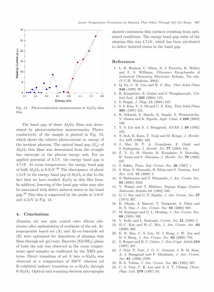
Fig. 13. Photoconduction measurements of Al2O3 thinfilm.
The band gap of these Al2O3 films was deter-
mined by photoconduction measurements. Photo-
conductivity of the sample is plotted in Fig. 13,
which shows the relative photocurrent vs. energy of
the incident photons. The optical band gap (Eg) of
Al2O3 thin films was determined from the straight
line intercept at the photon energy axis. For an
applied potential of 0.5V, the energy band gap is
4.7 eV. At room temperature, the energy band gap
of bulk Al2O3 is 6.2 eV.38 The discrepancy of about
1.5 eV in the energy band gap of Al2O3 is due to the
fact that we have studied Al2O3 in thin film form.
In addition, lowering of the band gap value may also
be associated with defect induced states in the band
gap.39 This idea is supported by the peaks at 3.8 eV
and 4.3 eV in Fig. 13.
4. Conclusions
Alumina sol was spin coated onto silicon sub-
strates after optimization of synthesis of the sol. Al-
isopropoxide based sol (A) and Al-sec-butoxide sol
(B) were optimized for deposition of alumina thin
films through sol–gel route. Bayerite [Al(OH)3] phase
of both the sols was observed in the room temper-
ature aged samples as confirmed by the XRD pat-
terns. Direct transition of sol A into α-Al2O3 was
observed at a temperature of 350◦C whereas sol
B exhibited indirect transition to α-Al2O3 through
θ-Al2O3. Optical and scanning electron micrographs
showed continuous film surfaces resulting from opti-
mized conditions. The energy band gap value of the
alumina film was 4.7 eV, which has been attributed
to defect induced states in the band gap.
References
1. L. K. Hudson, C. Misra, A. J. Perrotta, K. Wefersand F. S. Williams, Ullmann’s Encyclopedia of
Industrial Chemistry, Electronic Release, 7th edn.(V.C.H. Weinheim, 2004).
2. Q. Fu, C. B. Cao and H. S. Zhu, Thin Solid Films
348 (1999) 99.3. B. Ksapabutr, E. Gulari and S. Wongkasemjit, Col-
loid Surf. A 233 (2004) 145.4. S. Ruppi, J. Phys. 11 (2001) 847.5. S. S. Kim, Y. J. Oh and C. E. Kim, Thin Solid Films
305 (1997) 321.6. R. Kikuchi, S. Maeda, K. Sasaki, S. Wennerstrfm,
Y. Ozawa and K. Eguchi, Appl. Catal. A 239 (2003)169.
7. Y. S. Lin and A. J. Burggraaf, AIChE J. 38 (1992)445.
8. N. Itoh, K. Kato, T. Tsuji and M. Hongo, J. Membr.
Sci. 117 (1996) 189.9. J. Shu, B. P. A. Grandjean, E. Ghali and
S. Kaliaguine, J. Membr. Sci. 77 (1993) 181.10. Z. Y. Li, H. Maeda, K. Kusakabe, S. Morooka,
H. Anzai and S. Akiyama, J. Membr. Sci. 78 (1993)247.
11. S. Sakka, Trans. Ind. Ceram. Soc. 46 (1987) 1.12. S. Riaz, S. Shamaila, B. Khan and S. Naseem, Surf.
Rev. Lett. 15 (2008) 2.13. N. Bahlawane and T. Watanabe, J. Am. Ceram. Soc.
83 (2000) 2324.14. Y. Wakao and T. Hibbino, Nagoya Kogyo Gijutsu
Shikensko Hokoku 11 (1962) 588.15. G. C. Bye and G. T. Simkin, J. Am. Ceram. Soc. 57
(1974) 367.16. K. Okada, A. Hattori, T. Tanigushi, A. Nikui and
R. N. Das, J. Am. Ceram. Soc. 83 (2000) 928.17. M. Kumagai and G. L. Messing, J. Am. Ceram. Soc.
68 (1985) 500.18. V. Srdic and L. Radonjic, Ceram. Int. 21 (1995) 5.19. H.-C. Kao and W.-C. Wei, J. Am. Ceram. Soc. 83
(2000) 362.20. K. R. Han, C. S. Lim, M. J. Hong, J. W. Jan and
K. S. Hong, J. Am. Ceram. Soc. 83 (2000) 750.21. S. Resgui and B. C. Gates, J. Non-Cryst. Solids 210
(1997) 287.22. J. Nair, P. Nair, J. G. V. Ommen, J. R. H. Ross,
A. J. Burggraaf and F. Mizukami, J. Am. Ceram.
Soc. 81 (1998) 2709.23. B. E. Yoldas, J. Am. Ceram. Soc. 65 (1982) 387.24. C. S. Tsay, C. K. Lee and A. S. T. Chiang, Chem.
Phys. Lett. 278 (1997) 83.

688 S. Riaz et al.
25. J. Masalski, J. Gluszek, J. Zabrzeski, K. Nitsch andP. Gluszek, Thin Solid Films 349 (1999) 186.
26. M. Liu, Y. Liu, Z. Zeng and T. Peng, J. Chro-
matogr. A 1108 (2006) 149.27. J. Nawrocki, C. Dunlap, A. McCormick and P. W.
Carr, J. Chromatogr. A 1028 (2004) 1.28. M. S. M. Saifullah, D. J. Kang, K. R. V. Subrama-
nian, M. E. Well, K. Yamazaki and K. Kurihara,J. Sol–Gel Sci. Technol. 29 (2004) 5.
29. N. O. Zer, J. P. Cronin, Y. J. Yao and A. P. Tomsia,Sol. Energy Mater. Sol. Cells 59 (1999) 355.
30. B. Kasprzyk-Hordern, Adv. Colloid Interface Sci.
110 (2004) 19.31. Powder Diffraction File: Joint Committee on Powder
Diffraction Standards, ASTM, Philadelphia, 1967,Card No. 20-0011.
32. Powder Diffraction File: Joint Committee on PowderDiffraction Standards, ASTM, Philadelphia, 1967,Card No. 10-173.
33. Powder Diffraction File: Joint Committee on PowderDiffraction Standards, ASTM, Philadelphia, 1967,Card No. 11-517.
34. H. P. Klug and L. E. Alexander, X-ray Diffraction
Procedures for Polycrystalline and Amorphous Mate-
rials (Wiley, New York, 1974).35. S. Riaz and S. Naseem, J. Mater. Sci. Tech. 23
(2007) 4.36. M. Cernansky, Mater. Struct. 7 (2000) 3.37. S. Riaz and S. Naseem, A. J. Mater. Sci. 2008, in
press.38. G. V. Samsonov, HandBook of Oxides (Academy of
Sciences of Ukraine, USSR, 1969).39. I. Costina and R. Franchy, Appl. Phys. Lett. 78
(2001) 4139.