Embed Size (px)
Citation preview
Low Voltage Electrical Switchgear and Controlgear Assemblies
Practitioner Guide 05/09 Estate Management
Document Aim:
The aim of this Practitioners Guide (PG) is to provide guidance to those involved in the specification and procurement of low voltage electrical switchgear and controlgear assemblies to IEC 61439-2 and when ratified BS EN 61439-2
Document Synopsis:
This PG provides guidance for those engaged in the specification and procurement of low voltage electrical switchgear and controlgear assemblies to IEC 61439-2 and when ratified BS EN 61439-2 on the MOD estates. It may also prove useful to other Duty Holders who have interest in the operation and maintenance of such systems. The "Practitioners" to whom this Guide relates are Defence Estates (DE) personnel and other individuals or organisations tasked with the planning, designing, installing or maintaining LV electrical installations on the MOD estate. Its primary target audience includes construction professionals (e.g. Regional Prime Contractors), DE Facilities Managers, DE Project Managers and other staff involved in the management and design of new work, on the MOD estate, on behalf of DE. With assemblies, the permutations and configurations are effectively limitless. Fully type testing every manufactured variant within a modular system and each bespoke assembly or part of an assembly is simply not practical. Costs and time preclude this. While IEC has recognised this fundamental issue, it is equally clear that there must be a way of ensuring all assemblies meet defined performance and safety criteria. Accepting that the design of some assemblies is only ‘partially’ proven, or perhaps only routine tested, is no longer an option as it was under BS EN 60439-X. The categories of Type Tested Assembly (TTA) and Partially Type Tested Assembly (PTTA) have been discarded in favour of a design ‘verified assembly’. This is a classless designation where demonstration of design capability can be achieved by type test and/or by other equivalent means that include appropriate margins.
Property Directorate
2
. For design verification where volumes justify it, type testing will remain the preferred option for design verification, since it can, and does, lead to material and labour optimisations. When adaptations or bespoke arrangements are required, the standard offers other equivalent routes to design verification. These include comparison to a verified reference design, calculation, and interpolation from a verified design, measurement, etc. The ‘multiple option’ route to verification is strictly controlled. When, where and how each is used is defined. While it is possible to build a small assembly, of the order of 200A, with the only type tests being an earth continuity measurement and a dielectric test, the standard effectively limits the design verification of assemblies of the higher ratings to type test. It is now therefore essential that the performance expectations of assemblies are properly specified on order that a fully verified design can be achieved.
3
Document Information
Property Directorate Sponsor:
Simon Adamson
Date of Issue: 08 Oct 09
Contact if different from above Sponsor:
Andrew Dunn, Head Electrical Systems Construction Support Team, Defence Estates, Kingston Road, Sutton Coldfield. B75 7RL 94421 3622 / 0121 311 3622
Who should read this: CEstOs, Top Level Budget Holders, Defence Estates Advisors, Estate Managers, Facilities Managers and Property Managers/Site Estate Representatives Property Management Works Services (including the legacy work of EWCs/WSMs), DE Health and Safety Teams and any other person who is responsible for the planning, design, installation and maintenance of MOD Electrical Installations
When it takes effect: Immediately When it is due to expire: 08 Oct 10
Equality And Diversity Impact Assessment
This policy has been Equality and Diversity Impact Assessed in accordance with the Department’s Equality and Diversity Impact Assessment Tool against: Part 1 Assessment Only (no diversity impact found).
Document Control
Distribution Document Name:
Version No:
Version Date:
Author:
Reviewed By:
Review Date:
Version Control Date Issued Version Author Reason for Change
Related Documents e.g.Other JSP leaflets, etc e.g.Other practitioner guides e.g. EBMS Processes
4
Contents
Specific Requirements.............................................................................................5 Introduction..............................................................................................................5 Design verification ...................................................................................................6 Device substitution. .................................................................................................7 Other Standards......................................................................................................7 Annex A:..................................................................................................................8 Guidance on producing an assembly specification..................................................8
5
Guide to the minimum requirements for specifying low voltage electrical assemblies. A Guide to IEC 61439-2 and when ratified BS EN 61439-2
Specific Requirements
Annex A of this document identifies the minimum characteristics that must be detailed in the output specification for low voltage switchgear and controlgear assemblies in order to ensure that the design can be properly verified and that they are suitable for use. In addition to specifying the assemblies’ characteristics detailed design verification, in accordance with the above standard, for the assembly must be provided prior to installation and this requirement must be identified in the contract documentation or purchase order.
Introduction
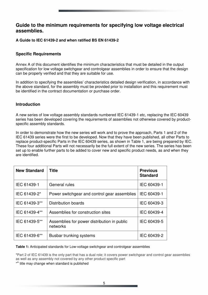
A new series of low voltage assembly standards numbered IEC 61439-1 etc, replacing the IEC 60439 series has been developed covering the requirements of assemblies not otherwise covered by product-specific assembly standards. In order to demonstrate how the new series will work and to prove the approach, Parts 1 and 2 of the IEC 61439 series were the first to be developed. Now that they have been published, all other Parts to replace product-specific Parts in the IEC 60439 series, as shown in Table 1, are being prepared by IEC. These four additional Parts will not necessarily be the full extent of the new series. The series has been set up to enable further parts to be added to cover new and specific product needs, as and when they are identified.
New Standard Title Previous Standard
IEC 61439-1 General rules IEC 60439-1
IEC 61439-2* Power switchgear and control gear assemblies IEC 60439-1
IEC 61439-3** Distribution boards IEC 60439-3
IEC 61439-4** Assemblies for construction sites IEC 60439-4
IEC 61439-5** Assemblies for power distribution in public networks
IEC 60439-5
IEC 61439-6** Busbar trunking systems IEC 60439-2
Table 1: Anticipated standards for Low-voltage switchgear and controlgear assemblies *Part 2 of IEC 61439 is the only part that has a dual role; it covers power switchgear and control gear assemblies as well as any assembly not covered by any other product specific part
** title may change when standard is published
6
Design Verification
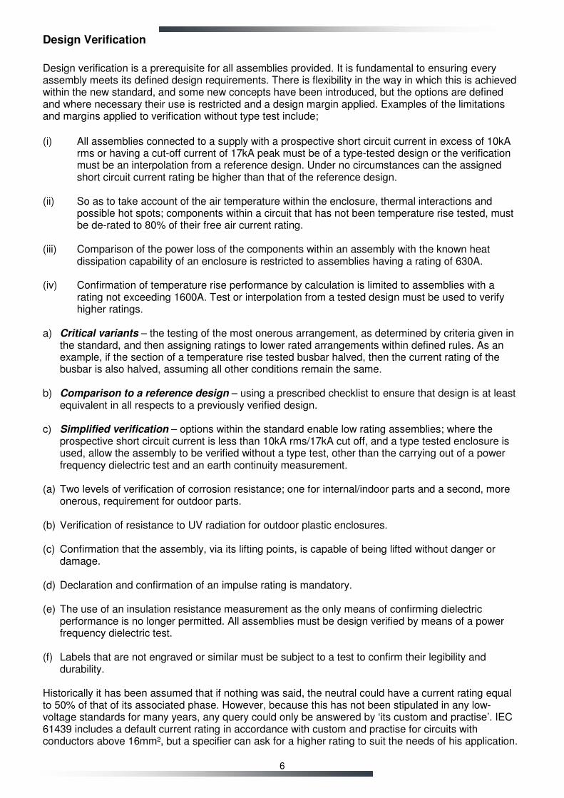
Design verification is a prerequisite for all assemblies provided. It is fundamental to ensuring every assembly meets its defined design requirements. There is flexibility in the way in which this is achieved within the new standard, and some new concepts have been introduced, but the options are defined and where necessary their use is restricted and a design margin applied. Examples of the limitations and margins applied to verification without type test include;
(i) All assemblies connected to a supply with a prospective short circuit current in excess of 10kA
rms or having a cut-off current of 17kA peak must be of a type-tested design or the verification must be an interpolation from a reference design. Under no circumstances can the assigned short circuit current rating be higher than that of the reference design.
(ii) So as to take account of the air temperature within the enclosure, thermal interactions and
possible hot spots; components within a circuit that has not been temperature rise tested, must be de-rated to 80% of their free air current rating.
(iii) Comparison of the power loss of the components within an assembly with the known heat
dissipation capability of an enclosure is restricted to assemblies having a rating of 630A. (iv) Confirmation of temperature rise performance by calculation is limited to assemblies with a
rating not exceeding 1600A. Test or interpolation from a tested design must be used to verify higher ratings.
a) Critical variants – the testing of the most onerous arrangement, as determined by criteria given in
the standard, and then assigning ratings to lower rated arrangements within defined rules. As an example, if the section of a temperature rise tested busbar halved, then the current rating of the busbar is also halved, assuming all other conditions remain the same.
b) Comparison to a reference design – using a prescribed checklist to ensure that design is at least
equivalent in all respects to a previously verified design. c) Simplified verification – options within the standard enable low rating assemblies; where the
prospective short circuit current is less than 10kA rms/17kA cut off, and a type tested enclosure is used, allow the assembly to be verified without a type test, other than the carrying out of a power frequency dielectric test and an earth continuity measurement.
(a) Two levels of verification of corrosion resistance; one for internal/indoor parts and a second, more
onerous, requirement for outdoor parts. (b) Verification of resistance to UV radiation for outdoor plastic enclosures. (c) Confirmation that the assembly, via its lifting points, is capable of being lifted without danger or
damage. (d) Declaration and confirmation of an impulse rating is mandatory. (e) The use of an insulation resistance measurement as the only means of confirming dielectric
performance is no longer permitted. All assemblies must be design verified by means of a power frequency dielectric test.
(f) Labels that are not engraved or similar must be subject to a test to confirm their legibility and
durability. Historically it has been assumed that if nothing was said, the neutral could have a current rating equal to 50% of that of its associated phase. However, because this has not been stipulated in any low-voltage standards for many years, any query could only be answered by ‘its custom and practise’. IEC 61439 includes a default current rating in accordance with custom and practise for circuits with conductors above 16mm², but a specifier can ask for a higher rating to suit the needs of his application.
7
In addition the ongoing question in respect of forms of separation has been answered. A device’s integral enclosure, for example the case of a moulded case circuit breaker, is defined as a means of providing separation from an adjacent circuit.
Device Substitution
BS EN 61439 series has determined in respect of temperature rise that devices can only be substituted if the alternative device has: (i) a power loss equal to or less than the original device; and (ii) the temperature rise of the alternative device’s terminals is less than or equal to that of the original device, when both are tested in accordance with the same product standard. BS EN 61439 series has determined in respect of short circuit performance, substitution can only be carried out without new verification if: (i) the original and alternative devices are from the same manufacturer; and (ii) that the manufacturer is prepared to certify that in all relevant respects the alternative device is equal to or better than the original device. This enables Schneider Electric, for example, to confirm that its NSX circuit breaker can be substituted for its NS model without an assembly builder having to repeat their design verifications. However, exchanging between different makes of device is precluded.
Other Standards
Compliance with BS EN/IEC 61439 series does not confer compliance with other EU directives, UK legislation or BSEN/IEC standards in relation to Hazardous areas, or other high risk environments where specific standards or legislation applies.
Annex A:
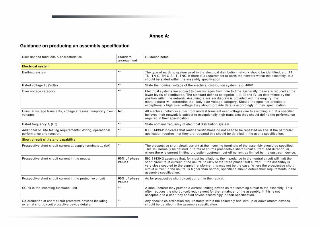
Guidance on producing an assembly specification
User defined functions & characteristics Standard arrangement
Guidance notes
Electrical system
Earthing system ** The type of earthing system used in the electrical distribution network should be identified, e.g. TT, TN, TN-C, TN-C-S, IT, TNS. If there is a requirement to earth the network within the assembly, this should be stated within the assembly specification.
Rated voltage Un (Volts) ** State the nominal voltage of the electrical distribution system, e.g. 400V
Over voltage category ** Electrical systems are subject to over voltages from time to time. Generally these are reduced at the lower levels of distribution. The standard defines categories I, II, III and IV, as determined by the position within the network. Assuming a system diagram is provided with the enquiry, the manufacturer will determine the likely over voltage category. Should the specifier anticipate exceptionally high over voltage they should provide details accordingly in their specification
Unusual voltage transients, voltage stresses, temporary over voltages
No All electrical networks suffer from modest transient over voltages due to switching etc. If a specifier believes their network is subject to exceptionally high transients they should define the performance required in their specification.
Rated frequency fn (Hz) ** State nominal frequency of electrical distribution system.
Additional on site testing requirements: Wiring, operational performance and function.
** IEC 61439-2 indicates that routine verifications do not need to be repeated on site. If the particular application requires that they are repeated this should be detailed in the user’s specification.
Short circuit withstand capability
Prospective short circuit current at supply terminals Icp (kA) ** The prospective short circuit current at the incoming terminals of the assembly should be specified. This will normally be defined in terms of an rms prospective short circuit current and duration, or, where there is current limiting protection upstream, cut-off current as limited by the upstream device.
Prospective short circuit current in the neutral 60% of phase values
IEC 61439-2 assumes that, for most installations, the impedance in the neutral circuit will limit the short circuit fault current in the neutral to 60% of the three-phase fault current. If the assembly is very close coupled to the supply transformer this may not be the case. Where the prospective short circuit current in the neutral is higher than normal, specifier’s should details their requirements in the assembly specification.
Prospective short circuit current in the protective circuit 60% of phase values
As for prospective short circuit current in the neutral.
SCPD in the incoming functional unit ** A manufacturer may provide a current limiting device as the incoming circuit to the assembly. This often reduces the short circuit requirement for the remainder of the assembly. If this is not acceptable to a user they should advise accordingly in their specification.
Co-ordination of short-circuit protective devices including external short-circuit protective device details.
** Any specific co-ordination requirements within the assembly and with up or down stream devices should be detailed in the assembly specification.
9
User defined functions & characteristics Standard arrangement
Guidance notes
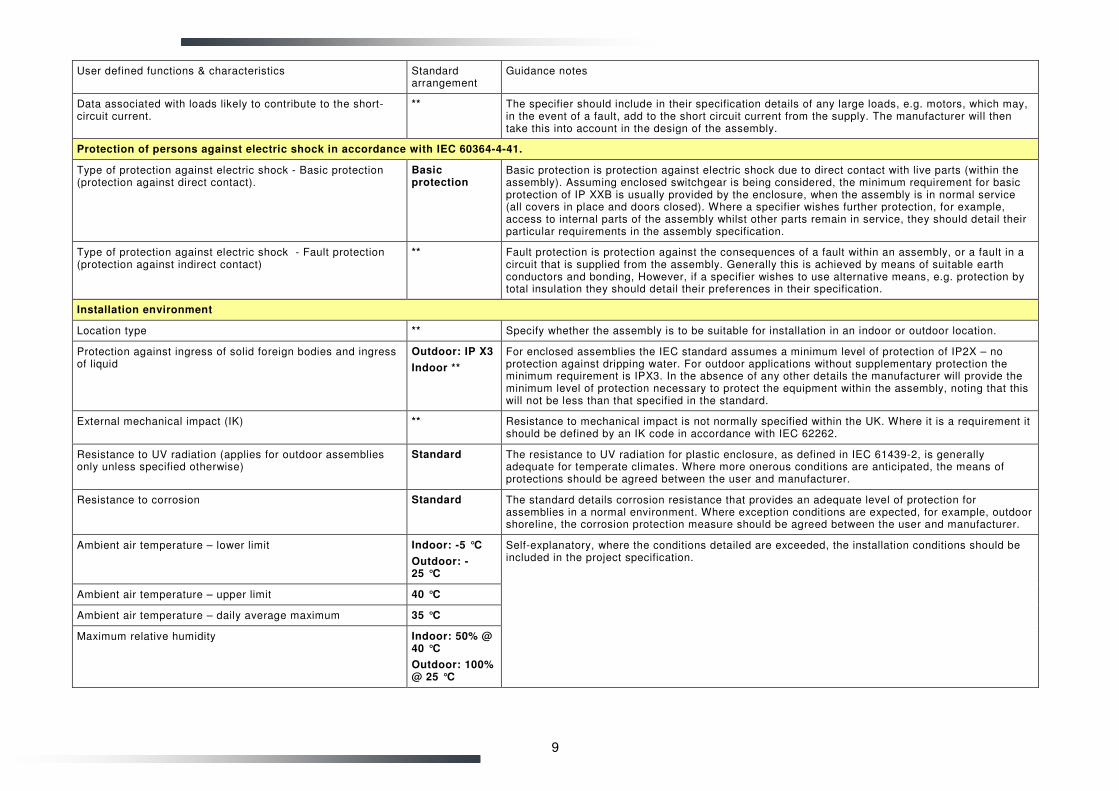
Data associated with loads likely to contribute to the short-circuit current.
** The specifier should include in their specification details of any large loads, e.g. motors, which may, in the event of a fault, add to the short circuit current from the supply. The manufacturer will then take this into account in the design of the assembly.
Protection of persons against electric shock in accordance with IEC 60364-4-41.
Type of protection against electric shock - Basic protection (protection against direct contact).
Basic protection
Basic protection is protection against electric shock due to direct contact with live parts (within the assembly). Assuming enclosed switchgear is being considered, the minimum requirement for basic protection of IP XXB is usually provided by the enclosure, when the assembly is in normal service (all covers in place and doors closed). Where a specifier wishes further protection, for example, access to internal parts of the assembly whilst other parts remain in service, they should detail their particular requirements in the assembly specification.
Type of protection against electric shock - Fault protection (protection against indirect contact)
** Fault protection is protection against the consequences of a fault within an assembly, or a fault in a circuit that is supplied from the assembly. Generally this is achieved by means of suitable earth conductors and bonding, However, if a specifier wishes to use alternative means, e.g. protection by total insulation they should detail their preferences in their specification.
Installation environment
Location type ** Specify whether the assembly is to be suitable for installation in an indoor or outdoor location.
Protection against ingress of solid foreign bodies and ingress of liquid
Outdoor: IP X3
Indoor **
For enclosed assemblies the IEC standard assumes a minimum level of protection of IP2X – no protection against dripping water. For outdoor applications without supplementary protection the minimum requirement is IPX3. In the absence of any other details the manufacturer will provide the minimum level of protection necessary to protect the equipment within the assembly, noting that this will not be less than that specified in the standard.
External mechanical impact (IK) ** Resistance to mechanical impact is not normally specified within the UK. Where it is a requirement it should be defined by an IK code in accordance with IEC 62262.
Resistance to UV radiation (applies for outdoor assemblies only unless specified otherwise)
Standard The resistance to UV radiation for plastic enclosure, as defined in IEC 61439-2, is generally adequate for temperate climates. Where more onerous conditions are anticipated, the means of protections should be agreed between the user and manufacturer.
Resistance to corrosion Standard The standard details corrosion resistance that provides an adequate level of protection for assemblies in a normal environment. Where exception conditions are expected, for example, outdoor shoreline, the corrosion protection measure should be agreed between the user and manufacturer.
Ambient air temperature – lower limit Indoor: -5 °C
Outdoor: -25 °C
Ambient air temperature – upper limit 40 °C
Ambient air temperature – daily average maximum 35 °C
Maximum relative humidity Indoor: 50% @ 40 °C
Outdoor: 100% @ 25 °C
Self-explanatory, where the conditions detailed are exceeded, the installation conditions should be included in the project specification.
10
User defined functions & characteristics Standard arrangement
Guidance notes
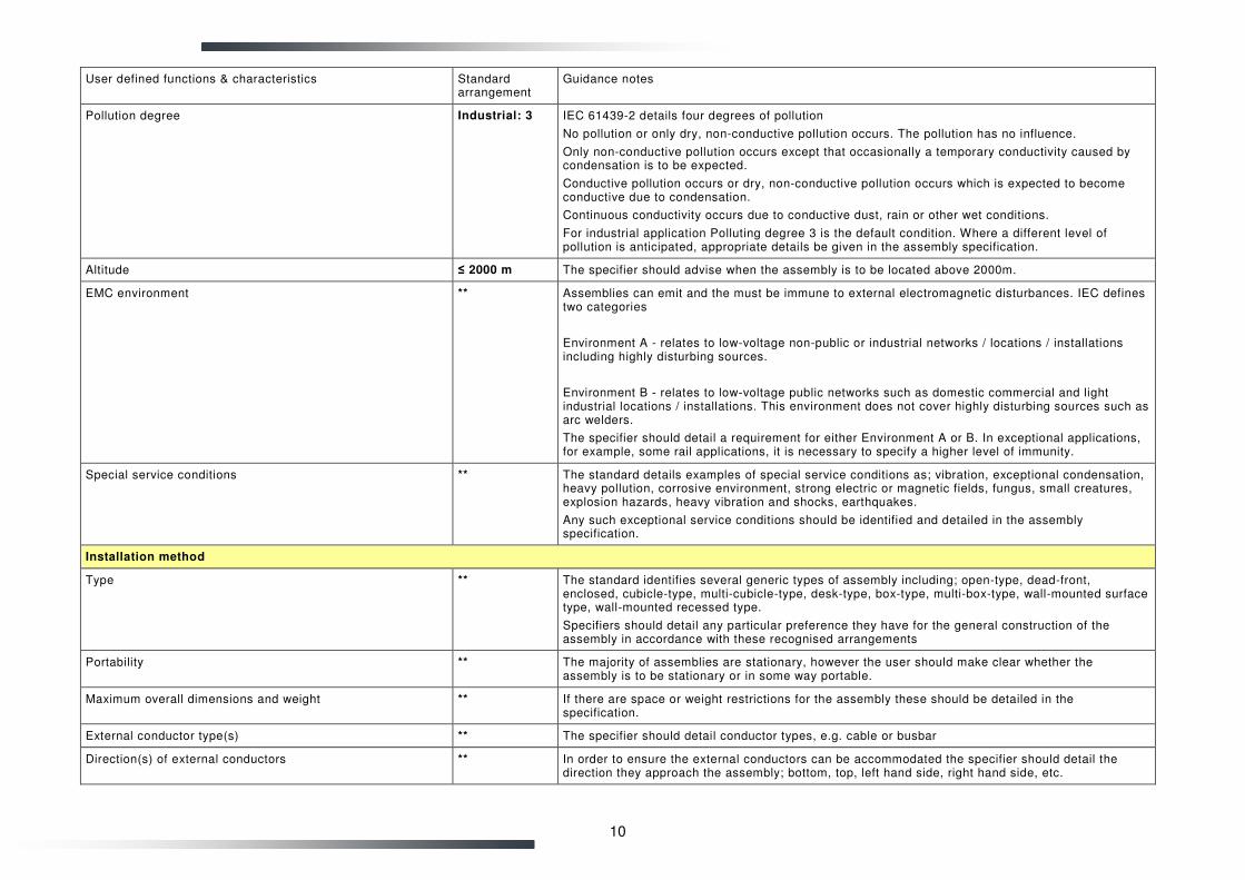
Pollution degree Industrial: 3 IEC 61439-2 details four degrees of pollution
No pollution or only dry, non-conductive pollution occurs. The pollution has no influence.
Only non-conductive pollution occurs except that occasionally a temporary conductivity caused by condensation is to be expected.
Conductive pollution occurs or dry, non-conductive pollution occurs which is expected to become conductive due to condensation.
Continuous conductivity occurs due to conductive dust, rain or other wet conditions.
For industrial application Polluting degree 3 is the default condition. Where a different level of pollution is anticipated, appropriate details be given in the assembly specification.
Altitude ≤ 2000 m The specifier should advise when the assembly is to be located above 2000m.
EMC environment ** Assemblies can emit and the must be immune to external electromagnetic disturbances. IEC defines two categories
Environment A - relates to low-voltage non-public or industrial networks / locations / installations including highly disturbing sources.
Environment B - relates to low-voltage public networks such as domestic commercial and light industrial locations / installations. This environment does not cover highly disturbing sources such as arc welders.
The specifier should detail a requirement for either Environment A or B. In exceptional applications, for example, some rail applications, it is necessary to specify a higher level of immunity.
Special service conditions ** The standard details examples of special service conditions as; vibration, exceptional condensation, heavy pollution, corrosive environment, strong electric or magnetic fields, fungus, small creatures, explosion hazards, heavy vibration and shocks, earthquakes.
Any such exceptional service conditions should be identified and detailed in the assembly specification.
Installation method
Type ** The standard identifies several generic types of assembly including; open-type, dead-front, enclosed, cubicle-type, multi-cubicle-type, desk-type, box-type, multi-box-type, wall-mounted surface type, wall-mounted recessed type.
Specifiers should detail any particular preference they have for the general construction of the assembly in accordance with these recognised arrangements
Portability ** The majority of assemblies are stationary, however the user should make clear whether the assembly is to be stationary or in some way portable.
Maximum overall dimensions and weight ** If there are space or weight restrictions for the assembly these should be detailed in the specification.
External conductor type(s) ** The specifier should detail conductor types, e.g. cable or busbar
Direction(s) of external conductors ** In order to ensure the external conductors can be accommodated the specifier should detail the direction they approach the assembly; bottom, top, left hand side, right hand side, etc.
11
User defined functions & characteristics Standard arrangement
Guidance notes
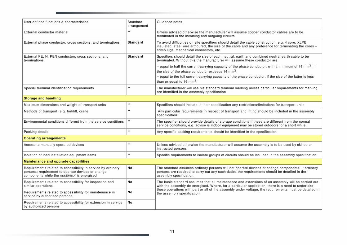
External conductor material ** Unless advised otherwise the manufacturer will assume copper conductor cables are to be terminated in the incoming and outgoing circuits.
External phase conductor, cross sections, and terminations Standard To avoid difficulties on site specifiers should detail the cable construction, e.g. 4 core, XLPE insulated, steel wire armoured, the size of the cable and any preference for terminating the cores – crimp lugs, mechanical connectors, etc.
External PE, N, PEN conductors cross sections, and terminations
Standard Specifiers should detail the size of each neutral, earth and combined neutral earth cable to be terminated. Without this the manufacturer will assume these conductor are;
– equal to half the current-carrying capacity of the phase conductor, with a minimum of 16 mm2, if
the size of the phase conductor exceeds 16 mm2;
– equal to the full current-carrying capacity of the phase conductor, if the size of the latter is less
than or equal to 16 mm2.
Special terminal identification requirements ** The manufacturer will use his standard terminal marking unless particular requirements for marking are identified in the assembly specification
Storage and handling
Maximum dimensions and weight of transport units ** Specifiers should include in their specification any restrictions/limitations for transport units.
Methods of transport (e.g. forklift, crane) ** Any particular requirements in respect of transport and lifting should be included in the assembly specification.
Environmental conditions different from the service conditions ** The specifier should provide details of storage conditions if these are different from the normal service conditions, e.g. advise is indoor equipment may be stored outdoors for a short while.
Packing details ** Any specific packing requirements should be identified in the specification
Operating arrangements
Access to manually operated devices ** Unless advised otherwise the manufacturer will assume the assembly is to be used by skilled or instructed persons
Isolation of load installation equipment items ** Specific requirements to isolate groups of circuits should be included in the assembly specification.
Maintenance and upgrade capabilities
Requirements related to accessibility in service by ordinary persons; requirement to operate devices or change components while the ASSEMBLY is energised
No The standard assumes ordinary persons will not operate devices or change components. If ordinary persons are required to carry out any such duties the requirements should be detailed in the assembly specification.
Requirements related to accessibility for inspection and similar operations
No
Requirements related to accessibility for maintenance in service by authorized persons
No
Requirements related to accessibility for extension in service by authorized persons
No
The basic standard assumes that all maintenance and extensions of an assembly will be carried out with the assembly de-energised. Where, for a particular application, there is a need to undertake these operations with part or all of the assembly under voltage, the requirements must be detailed in the assembly specification.
12
User defined functions & characteristics Standard arrangement
Guidance notes
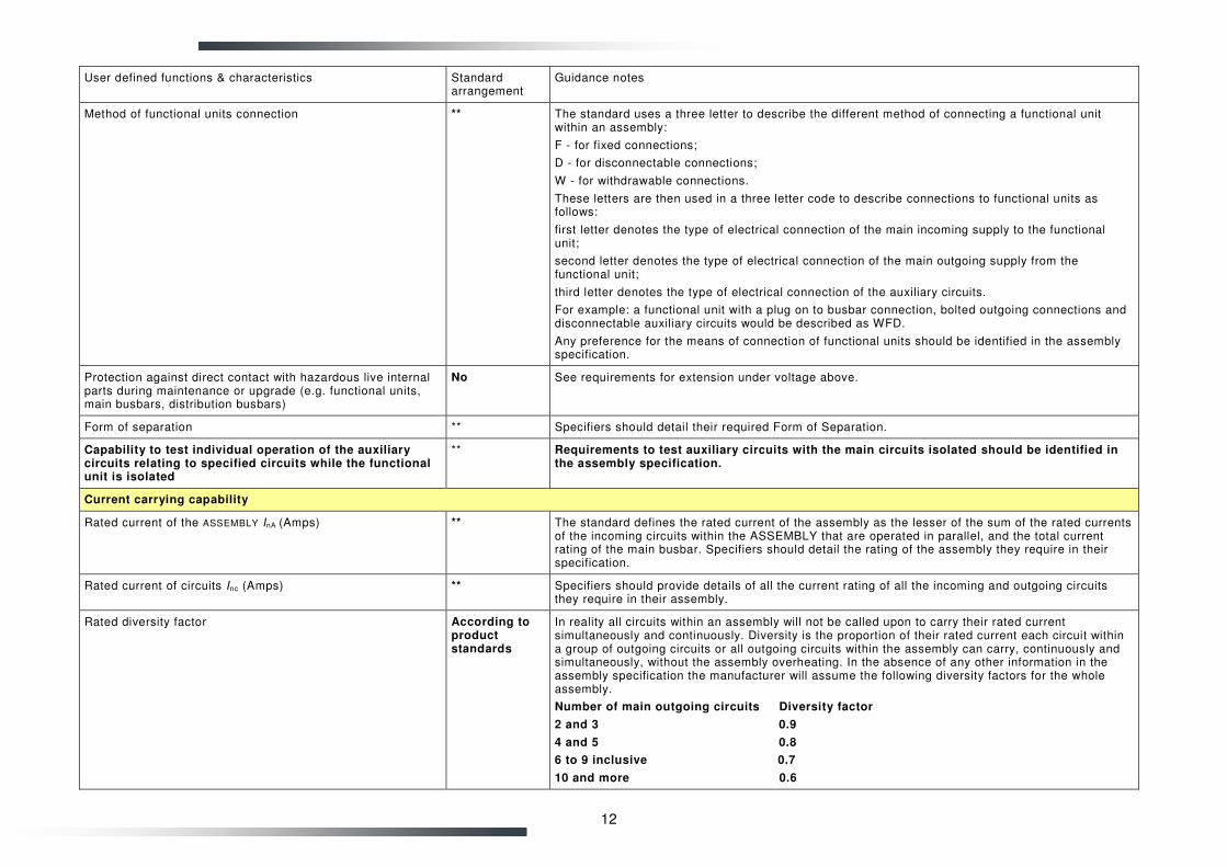
Method of functional units connection ** The standard uses a three letter to describe the different method of connecting a functional unit within an assembly:
F - for fixed connections;
D - for disconnectable connections;
W - for withdrawable connections.
These letters are then used in a three letter code to describe connections to functional units as follows:
first letter denotes the type of electrical connection of the main incoming supply to the functional unit;
second letter denotes the type of electrical connection of the main outgoing supply from the functional unit;
third letter denotes the type of electrical connection of the auxiliary circuits.
For example: a functional unit with a plug on to busbar connection, bolted outgoing connections and disconnectable auxiliary circuits would be described as WFD.
Any preference for the means of connection of functional units should be identified in the assembly specification.
Protection against direct contact with hazardous live internal parts during maintenance or upgrade (e.g. functional units, main busbars, distribution busbars)
No See requirements for extension under voltage above.
Form of separation ** Specifiers should detail their required Form of Separation.
Capability to test individual operation of the auxiliary circuits relating to specified circuits while the functional unit is isolated
** Requirements to test auxiliary circuits with the main circuits isolated should be identified in the assembly specification.
Current carrying capability
Rated current of the ASSEMBLY InA (Amps) ** The standard defines the rated current of the assembly as the lesser of the sum of the rated currents of the incoming circuits within the ASSEMBLY that are operated in parallel, and the total current rating of the main busbar. Specifiers should detail the rating of the assembly they require in their specification.
Rated current of circuits Inc (Amps) ** Specifiers should provide details of all the current rating of all the incoming and outgoing circuits they require in their assembly.
Rated diversity factor According to product standards
In reality all circuits within an assembly will not be called upon to carry their rated current simultaneously and continuously. Diversity is the proportion of their rated current each circuit within a group of outgoing circuits or all outgoing circuits within the assembly can carry, continuously and simultaneously, without the assembly overheating. In the absence of any other information in the assembly specification the manufacturer will assume the following diversity factors for the whole assembly.
Number of main outgoing circuits Diversity factor
2 and 3 0.9
4 and 5 0.8
6 to 9 inclusive 0.7
10 and more 0.6
13
User defined functions & characteristics Standard arrangement
Guidance notes
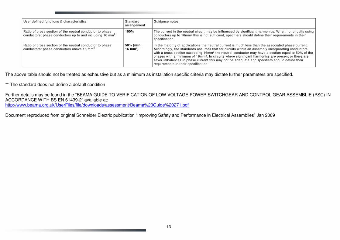
Ratio of cross section of the neutral conductor to phase conductors: phase conductors up to and including 16 mm
2.
100% The current in the neutral circuit may be influenced by significant harmonics. When, for circuits using conductors up to 16mm² this is not sufficient, specifiers should define their requirements in their specification.
Ratio of cross section of the neutral conductor to phase conductors: phase conductors above 16 mm
2
50% (min. 16 mm
2)
In the majority of applications the neutral current is much less than the associated phase current. Accordingly, the standards assumes that for circuits within an assembly incorporating conductors with a cross section exceeding 16mm² the neutral conductor may have a section equal to 50% of the phases with a minimum of 16mm². In circuits where significant harmonics are present or there are sever imbalances in phase current this may not be adequate and specifiers should define their requirements in their specification.
The above table should not be treated as exhaustive but as a minimum as installation specific criteria may dictate further parameters are specified. ** The standard does not define a default condition Further details may be found in the “BEAMA GUIDE TO VERIFICATION OF LOW VOLTAGE POWER SWITCHGEAR AND CONTROL GEAR ASSEMBLIE (PSC) IN ACCORDANCE WITH BS EN 61439-2” available at: http://www.beama.org.uk/UserFiles/file/downloads/assessment/Beama%20Guide%20271.pdf Document reproduced from original Schneider Electric publication “Improving Safety and Performance in Electrical Assemblies” Jan 2009